

Harsco Industrial MODU-FIRE W750MFD, MODU-FIRE W1000MFD, MODU-FIRE W1500MFD, MODU-FIRE W2000MFD Installation & Owner's Manual
MODU-FIRE® FD W Series
C.S.A. Design-Certified
750-2000 Rev 1.03 (06/17/14)
MODU-FIRE® FORCED DRAFT
GAS-FIRED WATER HEATER
750-1000-1500-2000
Model #:_______ Serial #______________________
Start-Up Date: _______________________
Harsco Industrial, Patterson-Kelley
155 Burson Street
East Stroudsburg, PA 18301
Telephone: (570) 476-7261
Facsimile: (570) 476-7247
www.harscopk.com
Complies with ANSI Z21.10.3/CSA 4.3
Gas Water Heaters
ASME Code, Section IV
Certified by Harsco Industrial, Patterson-Kelley
C.S.A. Design-Certified
Complies with ANSI Z21.10.3/CSA 4.3
Gas Water Heaters
© 2014 Harsco Industrial Patterson-Kelley
Printed 4/9/2014

MODU-FIRE
®
Forced Draft Gas-Fired Water Heater

®
MODU-FIRE
Forced Draft Gas-Fired Water Heater
1.0 INTRODUCTION .............................................................................................. 5
2.0 SAFETY ........................................................................................................... 5
2.1 General ............................................................................................................................ 5
2.2 Training ............................................................................................................................ 5
2.3 Safety Features ................................................................................................................ 6
2.4 Safety Labels ................................................................................................................... 6
2.5 Safety Precautions ........................................................................................................... 7
3.0 INSTALLATION ................................................................................................ 9
3.1 Receiving and Storage ..................................................................................................... 9
3.2 Compliance with Codes ................................................................................................. 10
3.3 Setup .............................................................................................................................. 10
3.4 Electrical Connections ................................................................................................... 12
3.5 Inlet Air and Exhaust Venting ......................................................................................... 14
3.6 Gas Piping ...................................................................................................................... 24
3.7 Water heater Water Piping ............................................................................................. 26
3.8 Burner and Ignition System ............................................................................................ 28
3.9 Pre-Start Check List ....................................................................................................... 28
3.10 Safety Checks ............................................................................................................. 29
3.11 Water Heater Operating Control ................................................................................. 30
3.12 Burner Adjustment ...................................................................................................... 31
4.0 OPERATION ...................................................................................................32
4.1 General .......................................................................................................................... 32
4.2 Lighting and Shut-Down Procedures ............................................................................. 33
5.0 MAINTENANCE ..............................................................................................
5.1 Maintenance and Inspection Schedule .......................................................................... 34
5.2 Cleaning the Burner ....................................................................................................... 35
5.3 Removing the Heat Exchanger ...................................................................................... 37
5.4 After All Repairs or Maintenance ................................................................................... 37
5.5 Sequence of Operation .................................................................................................. 37
5.6 Troubleshooting ............................................................................................................. 39
5.7 Manual Reset Error Codes – A## .................................................................................. 41
5.8 Auto-reset Error Codes – E## ........................................................................................ 42
33
6.0 PARTS/TECHNICAL SUPPORT .....................................................................43
6.1 Schematic Diagrams ...................................................................................................... 43
7.0 LIMITED WARRANTY .....................................................................................55
8.0 MODU-FIRE
®
FORCED DRAFT WATER HEATER FIRE TEST REPORT ......56

Reorder No. 6020-V2WHPK
Improper use may
result in fire or injury.
Read instructions/safety
manual before installing,
operating or servicing boiler.
c
!
WARNING
1998 HCS, Inc. 800-748-0241
®
MODU-FIRE
Forced Draft Gas-Fired Water Heater
If the information in this manual is not followed exactly, a fire or explosion may result causing proper-
ty damage, personal injury or loss of life.
Do not store or use gasoline or other flammable vapors or liquids in the vicinity of this or any other
appliance.
Installation and service must be performed by a qualified installer, service agency, or the gas supplier.
It is essential to read, understand, and follow the recommendations of this
manual before installing, operating, or servicing this equipment.
Installation and service must be performed by a qualified and knowledgeable
individual who has been trained on the MODU-FIRE® Forced Draft water heater. The same features
which permit this water heater to achieve high-efficiency performance make it unlike most other water
heaters of this general size, so it is important to understand how this water heater operates.
What to do if you smell gas:
• Do not try to light any appliance.
• Do not touch any electrical switch; do not use any phone in your building.
• Immediately call your gas supplier from a neighbor's phone. Follow the gas supplier's instruc-
tions
• If you cannot reach your gas supplier, call the fire department.
4
®
MODU-FIRE
Forced Draft Gas-Fired Water Heater
1.0 INTRODUCTION
The MODU-FIRE® Forced Draf t gas-fired water he ater is a revolutionar y advance. Harsco Industrial, PattersonKelley now combines f ull-modulation burner control and for ced draft advances wit h our time-tested modular hot
water water heater design. The r esult is a full-modulation water heater uti lizing r educed v ent si zing for installatio n
and cost efficiencies. This water heater combines the best of our earlier d esigns with a n ew generat ion of b urner ,
control a nd operating technology. You will ach ieve high part-load efficiencies – but without the complexi ty you
might expect in this t ype of hi gh perform ance water h eater. It is high per formance m ade simple and dependable
for years of trouble-free operation.
®
This manual covers installation of the MODU-FIRE
W1500MFD and W2000MFD. The m odel numbers will include a prefix and may include a suf fix to indicate special features or diff erent options. While deta ils m ay differ s lightl y, basic operat ion i s the s am e for all m odels. Water heaters are built to operate with natural gas or propane. Check the rating label for the correct gas type and
flow rate.
The water heater is onl y a part of the complete system. T his water heater m ay be fully operational and yet, because of poor circulat ion, controls , or ot her operat ing charact eristics, n ot deliver hot water to the desir ed loc ation.
Additional equipm ent such as tem perature sensor s, pum ps, flow switches, balancing valv es and check valves will
be required for satisfactory operation of any system. Harsco Industrial, Patterson-Kelley cannot be responsible for
the design or operation of such systems and a qualified engineer or contractor must be consulted.
Forced Draft water heaters W750MFD, W1000MFD,
2.0 SAFETY
2.1 GENERAL
The MODU-FIRE® Forced Draft gas-fired water heater must be:
• Installed, operated, and serviced in accordance with instructions contained in this manual and other supple-
mental MODU-FIRE
• Installed by qualified personnel in accordance with designs prepared by qualified engineers including: struc-
tural, mechanical, electrical, and other applicable disciplines.
• Operated and serviced in accordance with a comprehensive safety program determined and established by
the customer. Do not attempt to operate or service until such a program has been established.
• Operated and serviced by experienced, qualified, properly trained personnel in accordance with all applicable
codes, laws, and regulations.
• Installation and service must be performed by a qualified installer or service agency.
®
Forced Draft water heat er manuals.
2.2 TRAINING
Proper training is the best protection against accidents
It is essential to read, understand, and follow the rec-
ommendations of this manual before installing, operating, or servicing this equipment. Failure to do so could
result in serious injury, death, and/or property damage.
5
in death or serious injury. This signal word is to be limited to the most extreme situations.
sult in death or serious injury.
in minor or moderate injury. It may also be used to alert against unsafe practices.
NOTICE/NOTE - NOTICE is the preferred signal word to address practices not related to personal
injury. The safety alert symbol is not used with this signal word.
Reorder No. 6020-V2WHPK
Improper use may
result in fire or injury.
Read instructions/safety
manual before installing,
operating or servicing boiler.
c
!
WARNING
1998 HCS, Inc. 800-748-0241
®
MODU-FIRE
Operating and service personnel must be thoroughly familiar with the basic construction of the MODU-FIRE®
Forced Draft water heater, the use a nd locations of the contro ls
its various mechanism s, and all applicab le safety prec autions
and completely understood, contact the Harsco Industrial, Patterson-Kelley Technical Service toll free at:
(877) 728-5351.
. If any of the provisions of this m anual are not f ully
Forced Draft Gas-Fired Water Heater
, the oper ation of the water heater, adjustment of
2.3 SAFETY FEATURES
It is the responsibility of the customer to maintain the safety features of this machine, such as: guards, safety labels, safety controls, interlocks, lockout devices, etc., in place and operable.
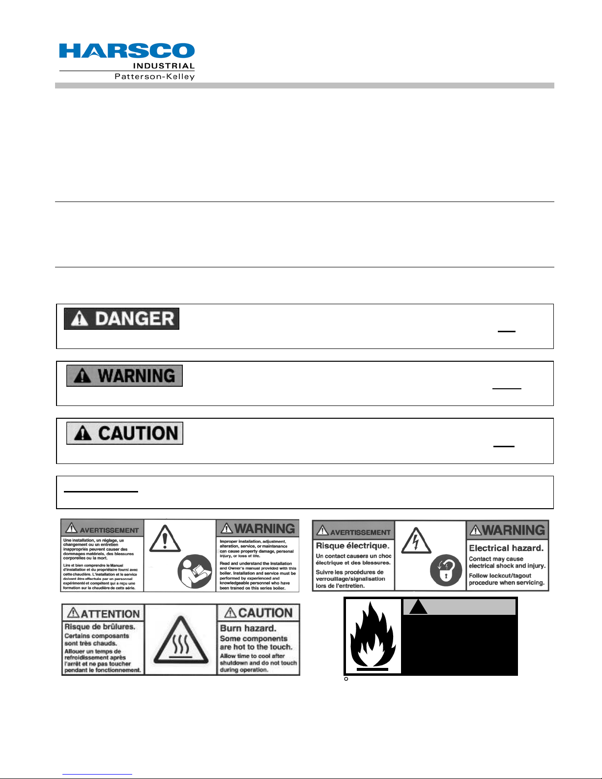
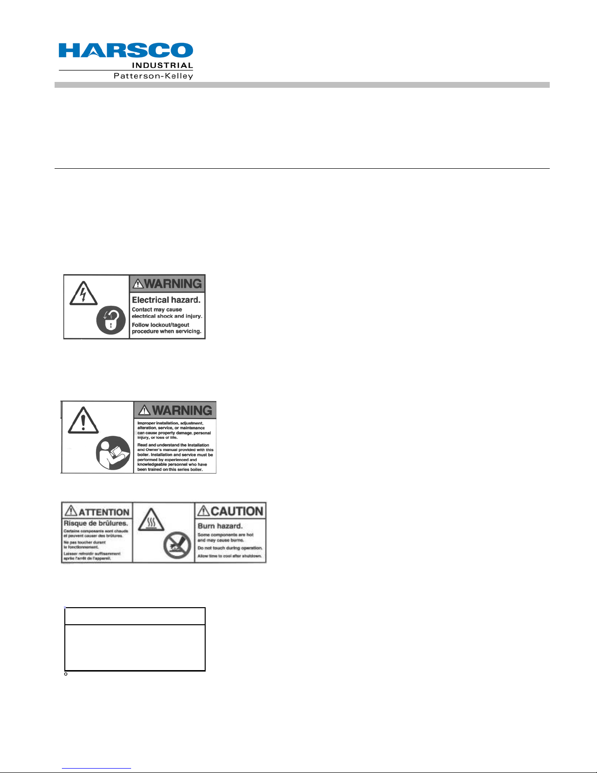
2.4 SAFETY LABELS
The following words are used in this manual to denote the degree of seriousness of the individual hazards.
indicates an imminently hazardous situation which, if not avoided, will result
indicates a potentially hazardous situation which, if not avoided, could re-
indicates a potentially hazardous situation which, if not avoided, may result
6
NOTE
Make sure this union is
tight before closing cabinet
cover after servicing boiler.
Reorder No. 8032-02NHAK
c
1998 HCS, Inc. 800-748-0241
®
MODU-FIRE
Forced Draft Gas-Fired Water Heater
The safety labels s hown a bove are af f ixed to your water hea ter. Altho ugh th e lab els are of hi gh qua lity, the y m a y
become dislodged or unr eadable over tim e. Contact Harsco Indus trial, Patterson-Kelley toll-free for replacement
labels at: (877) 728-5351
2.5 SAFETY PRECAUTIONS
Provide a suitable location for the wat er h eat er , away from normal personnel traff ic, with a dequate working spac e,
adequate clearances, pr oper ventilation and lighting, with a struc ture sufficiently strong and rigid to supp ort the
weight of the water heater, all piping, and accessories.
Proper lockout/tag out procedures must be employed whenever this unit is serviced.
2.5.1 Electrical Hazards
• Shock hazard! Properly lockout/tag out the electrical service and al l
other energy sources before working on or near the machine.
• Shock hazard! W ater heater is not rated for wash-down ser vice.
not spray water directly on this water heater or on any electrical
components.
• Electrical hazard! Do not alter wiring connections.
• Power down unit f or at least 10 minutes bef ore servicing inverter or
blower.
2.5.2 Burn, Fire, and Explosion Hazards
• Burn, fire, and explosion hazards! Installation must be in s trict con-
formance to all applica ble codes and standards including N FPA 54,
ANSI Z223.1 and CSA B.149.
• Hazard from incorrect fuels! Possible fire, explosion, overheating,
and damage. Do not use any fuels except the design fuel for the
unit.
• Over fire hazards ! High pres sure in gas or pro pane supply coul d re-
sult in over firing of other devices supplied from the same source.
• Fire and explosio n hazards! Close the main gas shutoff before ser-
vicing water heater.
Do
• Fire and expl osion hazards! Do not store or us e gasoline or other
flammable vapors or liquids in the vicinity of this or any other gas
fired appliance.
• Burn hazard! Poss ible hot surfaces. Do not touch the stack during
firing operations. Use only factory recommended vent components.
• Burn hazard! H ot fluids. U s e c autio n. A llow water he ater to cool be-
fore servicing or draining water heater.
7

2,000,000 Btu/hr
930
General Warning
General Warning
MODU-FIRE
• Fire and explos ion hazards! Use caution when servicing burner or
heat exchanger. Fuel may linger in the combustion chamber, vent
lines, or elsewhere.
• Gas leak hazard! Make s ure all connections to main burner are tig ht
when reassembling the burner.
• Gas leak hazard! All threa ded gas connectio ns must be made using
a pipe compound that is r es istant t o liquef ied petr oleum. Do not use
Teflon tape on threaded gas piping.
• Gas leak hazard! Check entire gas train for le aks after installation. If
there is a smell of gas, shut down the water heater, close all gas
valves and obtain im mediate assistance from factory-trained per sonnel and/or your local fire department.
• Over fire h azard! Possible f ire and explosion f rom excess gas pres-
sure. Make sure that gas inlet pr essure does not exceed 14 inches
W.C. to the water heater main gas valve.
• Over fire hazard! Possible fire and ex plosion . Possible m alf unction
of regulators and/or gas valves . Maint ain all gas train com ponents in
good condition. Do not a lter wiring connections. An nual inspection
by factory-trained personnel for proper set-up and operation is recommended.
®
Forced Draft Gas-Fired Water Heater
2.5.3 Crush Hazards
• Lifting hazards! Use properly rated lifting
equipment to lift and position the water
heater. The load is unbalanced. Test
balance before lifting 3 ft. above the floor.
Do not allow personne l ben eath the lif ted
load. Refer to approx imate weights in
the table:
• Bump hazard from overhead piping. In-
stall piping with adequate vertic al clearance.
2.5.4 Chemical Hazards
• Chemical hazards from cleaning products. Use c aution when cleaning the system . The
use of professional assistance is recomm ended. Use safe pr ocedures for the dispos al of
all cleaning solutions.
• Over fire and under fire hazards ! Possible fire, exp losion, overheat-
ing, and component failur e. Do not attem pt t o adjust f iring rate of the
water heater. The firing r ate must be adjusted only by factory-trained
personnel.
Water Heater Size
Weight in
Pounds
750,000 Btu/hr 745
1,000,000 Btu/hr 745
1,500,000 Btu/hr 915
8
General Warning
General Warning
NOTICE! Note any damage, suspected potential damage, or shortage of materials on the freight bill
its side or tipped over in transit.
MODU-FIRE
2.5.5 Pressure Hazards
• Pressure hazard! Hot fluids. Install isol ation valves on water heater water inlet and out-
let. Make sure isolation valves are closed before servicing water heater.
• Pressure hazard! Hot fluids. Test safety relief valve bimonthly for proper op eration. Do
not operate water heater with faulty relief valve.
2.5.6 General Hazards
• Tripping hazard! Do not install piping on floor s urfaces. Maintain clear pat h ar ou nd water
heater.
• Slip and fall hazard! Use drip pan to catch water while draining th e water heate r. Main-
tain dry floor surfaces.
• Slip and fall hazard! Through-the-wall vents s hall not terminate over public walkways or
over an area where condensate or vapor could create a nuisance or hazard.
• Fall hazard! Do not stand on any part of the water heater.
• Catch hazard! Do not wear rings, jewelry, long ha ir, loose clothing while working on the
water heater.
®
Forced Draft Gas-Fired Water Heater
3.0 INSTALLATION
Installation and service must be performed by a qualified installer or service
agency.
3.1 RECEIVING AND STORAGE
3.1.1 Initial Inspection
Upon receiving the water heater, inspect it for signs of shipping damage. Since some dam age m ay be hid-
den, we recommend unpac king the water hea ter, removing the top, fr ont, and side covers and inspect the water
heater. Verify that the total number of pieces shown on the packing slip agrees with those actually received.
and immediately notify the carrier. File all claims for shortage or damage with the carrier. Claims for
hidden damages must be filed with your carrier within 7 days. The water heater carton is equipped
with a “Tip (N) Tell”. If "Tip (N) Tell” arrow point is blue, that indicates that the package has been on
3.1.2 Storage Prior to Installation
If the water heater is not installed immediately, it must be stored in a location adequately protected from the
weather and freezing con ditions, preferably indoors . If this is not possible, then it should rem ain in the shipping
container and be covered by a tarpaulin or other waterproof covering.
NOTICE! Controls and other equipment that are damaged or fail due to weather exposure are not
covered by warranty.
9

®
MODU-FIRE
Forced Draft Gas-Fired Water Heater
3.2 COMPLIANCE WITH CODES
The MODU-FIRE® Forced Draft water heater with standard com ponents and many opt ions complies with American National Standard/CSA Standard ANSI Z21.10.3/CSA 4.3, Gas-Fired Low Pressure Steam and Hot Water
Water heaters, latest edition. The heat exchanger is cons tructed and stam ped in accordance with ASME Water
heater and Pres sure Vess el Code , Sect ion IV HLW for 160 psig maxim um oper ating pres sure and /or 21 0º F m aximum temperature.
Installation of the water he ater must conform to all the requir ements of all national, state and local codes established by the authorit ies having jurisdiction or, in t he absence of such requirem ents, in the U.S. to the Nation al
Fuel Gas Code, ANSI Z22 3.1/NFPA 54, latest edition. In Canada, the equipm ent shall be insta lled in accordance
with the current Installatio n Code for Gas Burning Applianc es and Equipment, CSA-B.149.1, and applicabl e Provincial Regulations f or the class, which should be carefully followed in all cas es. Authorities having jurisdiction
should be consulted before installations are made.
Where required b y local c o des, th e i nstal lat io n must conform to Am eric an Soc iet y of Mec h an ical En gin eer s Saf ety
Code for Controls and Safety Devices for Automatically Fired Water heaters (ASME CSD-1).
In the Commonwealth of Massachusetts , (a) this unit must be instal led by a licens ed pipe fitter / plum ber, (b) field
installed gas cocks must be “T” handle type, (c) piping of condensate s hall conform to t he State Plumbing Code,
and (d) refer to the Massachusetts supplement for further details.
.
3.3 SETUP
3.3.1 Foundation
Provide a firm, level foundation, preferably of concrete.
NOTICE! The water heater may be installed on a combustible floor; however, the water heater must
never be installed on carpeting.
NOTICE! This water heater is certified for indoor installation only.
3.3.2 Placement
The water heater must be level and upright to function properly. Use shims or other approved structural devices
to properly level water heater.
10
D
®
MODU-FIRE
Forced Draft Gas-Fired Water Heater
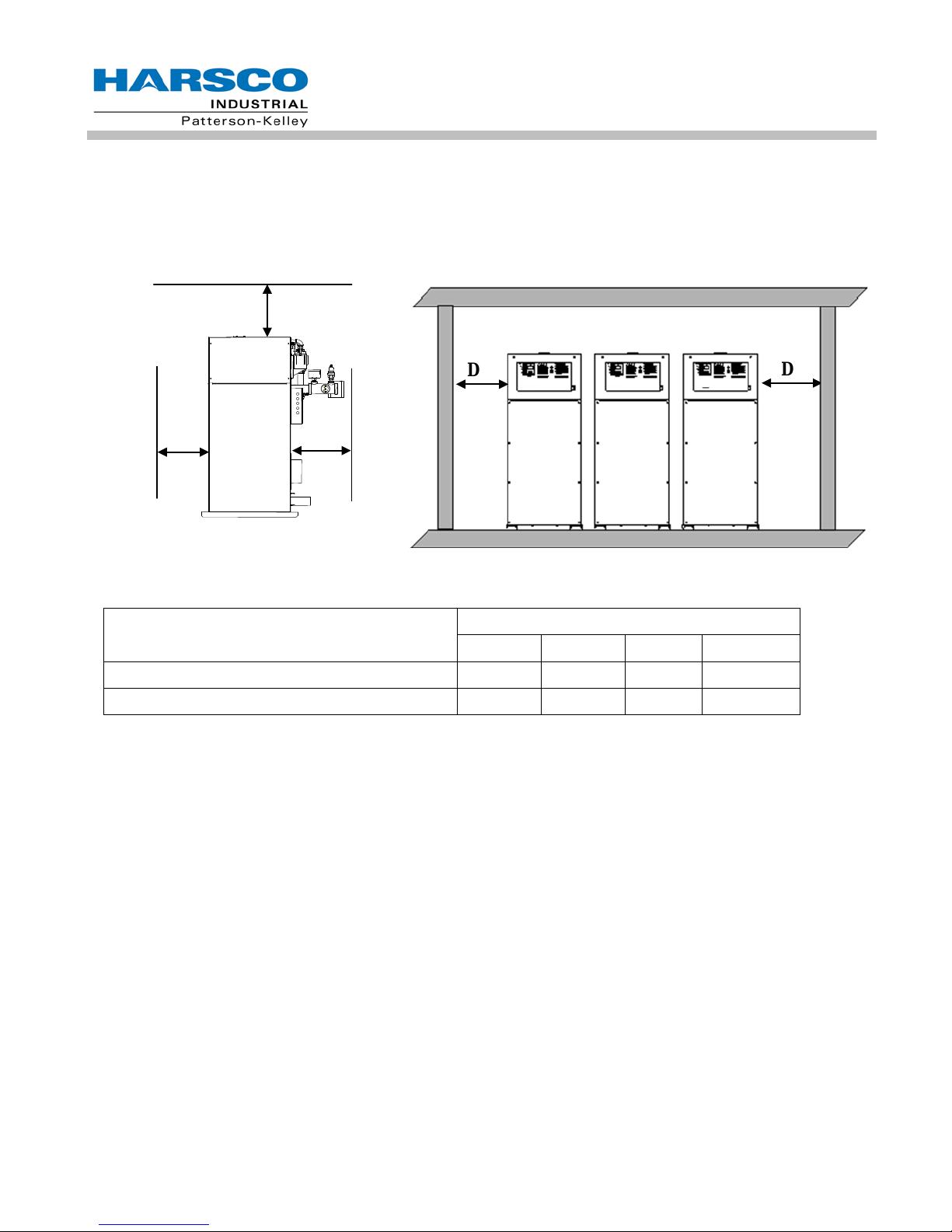
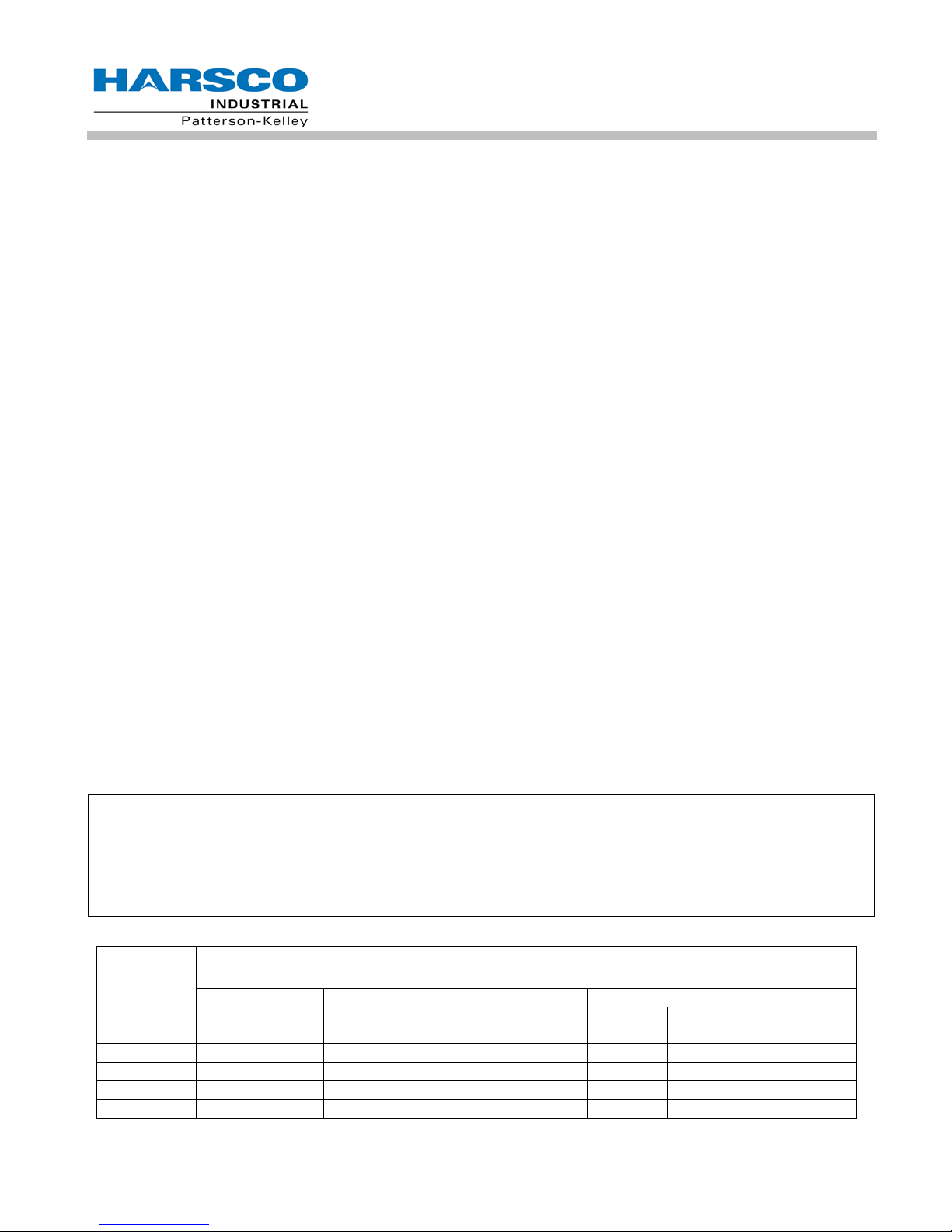
3.3.3 Installation Clearances
If the water heater is to be installed near combustible surfaces, six (6”) inches minimum clearance to the combustible surface must be maintained. Failure to provide for the service access clearances, even with non-combustible
surfaces, may cause future problems servicing the water heater. The water heater must be installed in a space
large in comparison to the water heater as described in the National Fuel Gas Code, N FPA 54/ANSI Z223.1, latest edition.
C
D
A B
Clearances from Adjacent Walls, Side Clearances for a Row of Water heaters
Ceiling and Obstructions
Type of Surface Dimensions (inches)
A B C† D
CSA Minimum Clearances to Combustibles 24 24* 24 24
Recommended Service Clearances 30 24* 24 24**
† “C" dimension includes clearance to remove the burner. Do not put pipes, ducts, etc. in this area above the water heater.
*CSA minimum. Actual clearance depends upon venting requirements.
** Service access need be only on one side of a water heater or row of water heaters. Water heaters may be installe d imme-
diately adjacent to each other. However, Harsco Industrial, Patterson-Kelley recommends this clearance between each water
heater when there is insufficient access at the rear to allow for service and adjustment.
11
®
MODU-FIRE
Forced Draft Gas-Fired Water Heater
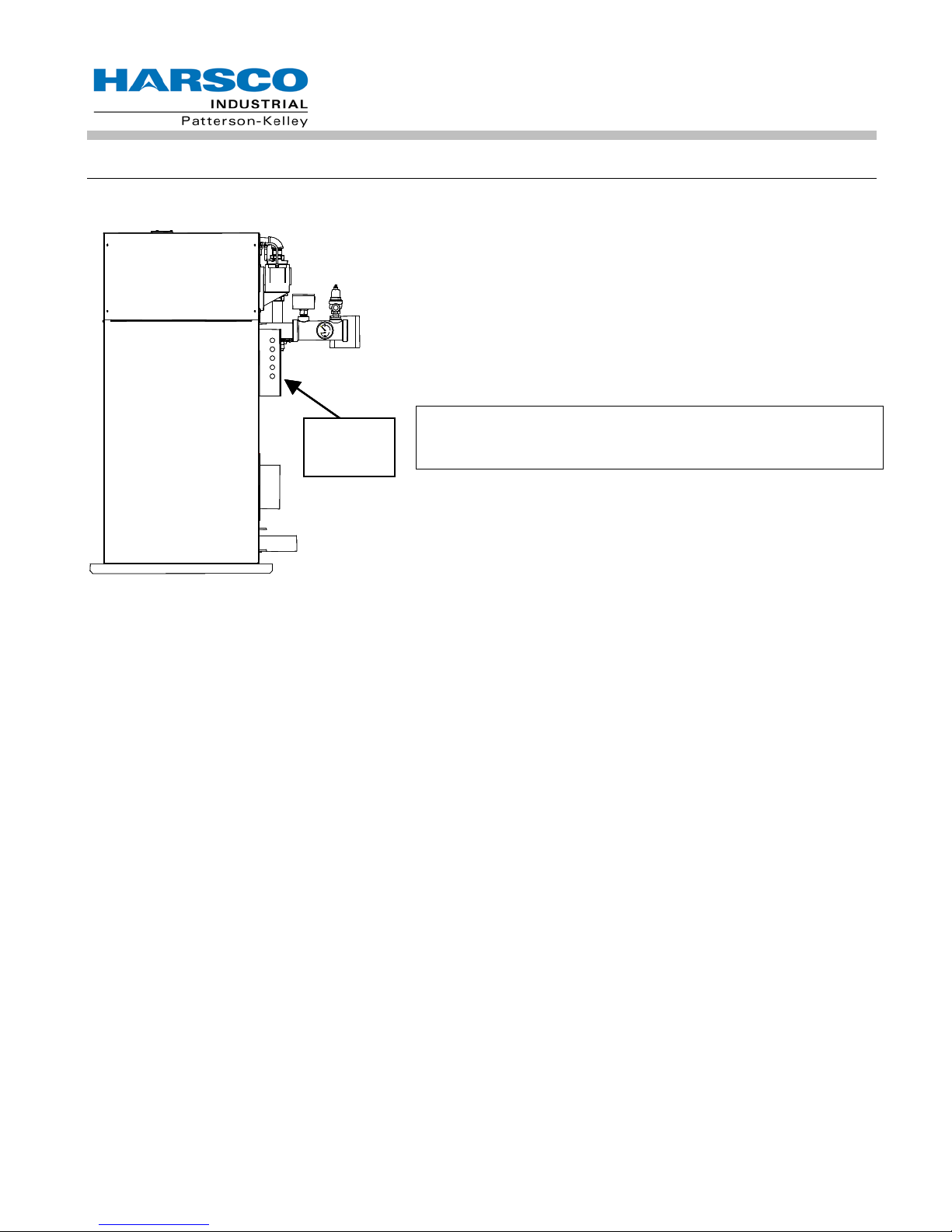
3.4 ELECTRICAL CONNECTIONS
All field wiring connections for power and controls are in the junction box on the back of the water heater.
The water heater wiring label is attached to the inside front door
of the water heater. An external electrical discon nect ( not supplied with the water heater) with adequate overload protection is
required. The water heater must be grounded in accordance
with local codes or in the absence of such requirements, in the
U.S. with National Electrical Codes, ANSI/NFPA No. 70 latest
edition and in Canada, wire according to the current Canadian
Electrical Code.
Electrical
Connections
NOTICE! A dedicated earth ground (green wire) is required to avoid nuisance shutdowns. It is also important
that proper polarity be maintained.
The junction box at the rear of the water heater contains terminal
strips for power and control connections. A detailed schematic of
the connections is shown in 6.1.7. These conn ec ti ons ar e as follows:
3.4.1 High Voltage (HV) Terminal Block
The water heater po wer cir cuit req uires 240 volts , sin g le phase, 60 her t z, with a dedicat ed neutral and ground as
labeled. The voltage between L1 (HV-1) and L2 (HV-2) must be approximately 230V, while the voltage from each
line to the neutral (HV-3) must be approximately 120V AC. Electrical service must be rated for 17 amps minimum.
Before starting the water heater, check to ensure that the proper voltage and amperage are connected to the
water heater and that the water heater is connected to a suitable fused disconnect switch or circuit breaker.
There must be less than 1.0V from Neutral (HV-3) to Ground (HV-10)
120VAC Switched Output- This contact closes when the water heater is switched on. This provides 120VAC
5Amp service to HV12 and HV13. The neutral for this circuit is provided on HV4 and HV5. When the water
heater is switched off, these terminals are switched off as well.
3 Way Valve- This output is normally energized, maintaining the three way valve in the position to provide heat to
the building. The Domestic Hot Water (DHW) call for heat de-energizes this circuit, causing the 3 way valve to
drive to the position to provide heat to the DHW loop. This output provides 120VAC 0.5Amp service to HV14.
The neutral for this circuit is provided on HV 6.
DHW Pump Relay w/Delay Off - This output is enabled when there is a call for DHW. When the call for heat is
removed, the output remains enabled for a predetermined period of time. The time delay is adjustable through the
ENVI™ control system. This output provides 120VAC 0.5Amp service to HV15. The neutral for this circuit is
provided on HV 7.
Circ Pump Relay w/Delay Off - This output is enabled when there is a call for heat. When the call for heat is
removed, the output remains enabled for a predetermined period of time. The time delay is adjustable through the
ENVI™ control system. This output provides 120VAC 0.5Amp service to HV16. The neutral for this circuit is
provided on HV 8.
12
®
MODU-FIRE
Damper Relay - This output is enabled when the call for water is enabled. This output provides 120VAC service
to HV17. The neutral for this circuit is provided on HV 9. This circuit is for pilot duty only (less than 1 amp).
Master Alarm Relay – This contact closes in the event of an alarm output from the water heater control,
connecting HV18 and HV19.
Flame Detected Relay – This contact closes whenever the water heater is firing, connecting HV20 and HV21.
Forced Draft Gas-Fired Water Heater
3.4.2 Low Voltage (LV) Terminal Block
Enable/Disable– Use for water heater enable. Closing this circuit allows the water heater to run. Opening this
circuit prevents the water heater from running, provided the remote/local enable switch is in the remote position.
This circuit is energized by the water heater. It has a 24VAC potential. Devices connected to these terminals
must be rated for 24VAC.
The remote/local enable switch bypasses the Enable/Disable (LV1 to LV2)
when in the local position. Do not connect safety devices into the Enable/Disable circuit.
Auxiliary Low Water Cutoff – These terminals are used for connection of a secondary low water cutoff used in
the system. This circuit is energized by the water heater. It has a 5V potential. Devices connected to these
terminals must be rated for 5V.
Start Interlock - Use for attachment of an additional field safety device to the water heater control circuit. Closing
this circuit allows the water heater to run. Opening this circuit prevents the water heater from running. This circuit
is energized by the water heater with a 5V potential. Devices connected to these terminals must be rated for 5V.
Outdoor Temp Sensor – LV7 and LV8 are connected to the outdoor temperature sensor. The temperature
control must be programmed to run an outdoor air schedule. The outdoor air sensor and programming help are
available from the ENVI™ Advanced User’s Guide (ENVI™ 09) or from your local Harsco Industrial, PattersonKelley Representative. This circuit is energized by the water heater with a 5V potential. The temperature sensor
must be a NTC having 12k@25°C.
DHW Stat/Sensor – LV9 and LV10 are connected to the DHW temperature sensor or thermostat. This circuit is
energized by the water heater with a 5V potential. The temperature sensor must be a NTC having 12k@25°C.
Header Temp Sensor – LV11 and LV12 are connected to the header temperature sensor. This circuit is
energized by the water heater with a 5V potential. The temperature sensor must be a NTC having 12k@25°C.
DHW Flow Switch – LV13 is energized by the water heater with a 5V potential. This circuit connects through a
flow switch on the domestic side of a domestic hot water system. The flow switch should close upon flow to
provide a closed circuit back to LV14.
Analog Input– Remote signal for controlling the water heater. The water heater can be operated in a remote
setpoint or a remote firing rate control mode. Input 0-10VDC signal only. The temperature control must be
programmed to run with the analog input.
MODBUS
ENVI™ control Advanced Users Guide for more information)
®
– LV19 and LV20 are used for connecting a MODBUS® building management system. (See the
Cascade – LV21 and LV22 are used to connect between water heaters that are part of a Master/Member
Network. Up to 24 water heaters may be connected together. (See the ENVI™ control Advanced Users Guide for
more information)
13
®
MODU-FIRE
Forced Draft Gas-Fired Water Heater
3.5 INLET AIR AND EXHAUST VENTING
3.5.1 Applicable Codes & Standards
CODES
United States:
NFPA 54/ANSI Z223.1 National Fuel Gas Code
NFPA/ANSI 211 Chimneys, Fireplaces, Vents and Solid Fuel Burning Appliances
Canada
CAN/CSA B149.1 Installation Codes for Gas Burning Equipment
STANDARDS
UL 1738 Venting Systems for Gas-Burning Appliances, Categories II, III, and IV
These codes and standards contain information for the venting of gas fired appliances, including, but not limited to
vent sizing, location, clearance to combustibles, and safe installation practices. The installation must comply with
both the above Federal Codes and with state, provincial and local codes.
Design and installation of venting systems should be done only by qualif ied
and knowledgeable venting systems personnel and in accordance with vent system manufacturer’s
installation instructions. Installing a water heater or vent system using improper installation methods
or materials can result in serious injury or death due to fire or asphyxiation.
Before connecting a water heater to a venting system, it must be determined whether the water heater is to be installed in a conventional or direct vent configuration. In the
US, provisions for combustion and ventilation air must be in accordance with NFPA 54/ANSI Z223.1,
National Fuel Gas Code, latest edition, or applicable provisions of the local building codes. In Canada, combustion and ventilation air openings shall comply with CAN/CSA B-149.1 Natural Gas and
Propane Installation Code.
For correct installation of vent system , read all of these instructions and refer to vent manufacturer’s instructions.
Failure to use a proper vent system (types and materials), as described in this manual will void the
water heater warranty and may result in rapid deterioration of the venting system, creating a health or
life safety hazard.
Faulty vent installation can allow toxic fumes to be released into living areas. This may cause property damage, serious bodily injury or death.
14
®
MODU-FIRE
3.5.1.1 Gas Vent Categories
Several codes and standards have categorized appliances in accordance with the flue gas temperature and pressure produced by the appliance. Categories are defined as follows:
• Category I An appliance that operates with a non-positive vent static pressure and with a vent tempera-
ture that avoids excessive condensate production in the vent.
• Category II An appliance that operates with a non-positive vent static pressure and with a vent tempera-
ture that may cause excessive condensate production in the vent.
• Category III An appli anc e that operates with a positive vent static pressure and w ith a vent tem per atur e
that avoids excessive condensate production in the vent.
• Category IV An appliance that operates with a positive vent static pressure and with a vent temperatur e
that may cause excessive condensate production in the vent.
• Direct Vent An appliance that is constructed and installed so that all air for combustion is derived directly
from outdoors and all flue gases are discharged to the outdoors.
3.5.1.2 Venting Materials for Flue/Exhaust Systems
®
MODU-FIRE
and with a temperature that is likely to cause condensation in the vent. Therefore, any venting system used with
the MODU-FIRE
as specified in the latest edition of NFPA 54/ANSI Z223.1 in the US or the latest edition of CAN/CSA B-149.1 in
Canada.
Forced Draft water heaters are Category IV appliances, which vent with a positive exhaust pressure
®
Forced Draft water heater must comply with the requirements for Category IV venting systems
Forced Draft Gas-Fired Water Heater
The venting materials listed below are intended for the venting of gas burn-
ing appliances only. Do not use these venting materials for venting liquid or solid fuel (such as oil, kerosene, wood or coal) appliances.
Maintain clearances to combustibles as listed in the vent manufacturer’s installation instructions or as
set forth in the codes and standards listed in this section.
Do not use these vent pipes for incinerators of any sort.
3.5.2 Combustion Air
Combustion air must be free from dust, lint, etc. The presence of such materials in the air supplied to the burner
could cause nuisance "Low Air" shutdowns or premature burner failure. The water heater should not be operated
during construction while the possibility of drywall dust, demolition dust, etc. exists.
The combustion air supply must be completely free of chemical fumes which may be corrosive when burned in the
water heater. Common chemicals which must be avoided are fluorocarbons and other halogenated compounds,
most commonly present as refrigerants or solvents, such as freon, trichloroethylene, perchlorethylene, chlorine,
etc. These chemicals, when burned, form acids which quickly attack the water heater and the water heater stack.
The result is improper combustion and premature water heater failure.
Under no circumstances shall the water heater room ever be under a negative pressure. Particular care should be taken when exhaust fans, compressors, air-handling units or
other equipment may rob air from the water heater. Note that this equipment might be in rooms other
than the water heater room.
15
INDOOR AIR SUPPLY
OUTDOOR AIR SUPPLY
TWO OPENINGS
VERT
HORIZ
W750MFD
750
1500
250
188
188
375
W1000MFD
1000
2000
333
250
250
500
W1500MFD
1500
3000
500
375
375
750
W2000MFD
2000
4000
667
500
500
1000
®
MODU-FIRE
3.5.2.1 Air Inlet Requirements – United States (NFPA 54/ANSI Z223.1 & NFPA/ANSI 211)
When air is supplied from ins ide th e bu ildin g, the t ot a l require d vo lume shall be the sum of the required volume for
all the appliances loca ted in the mec hanical room. Adjacent rooms furnished wit h fixed openings communic ating
directly with the mec hanical room are considered part of the required volume. T he minimum volum e is 50 ft
1000 Btu/hr (4.8 m
the required minimum volume shall be sized as follows:
3
/kW) of installed appliance input c apacity. Open ings used to connec t indoor spaces to obta in
Forced Draft Gas-Fired Water Heater
3
per
• When rooms are on the same floor, each opening shall have an area equal to 1 square inch for each
1000 Btu/hr (2200 mm
2
/ kW) of installed appliance input c apacity, but not less than 100 square inches.
One opening should commenc e less than 1 2 inches a bove the f loor and th e othe r less than 12 inches below the ceiling. The minimum dimension of air openings shall be 3 inches.
• When rooms are on different floors, each opening sh all have an area equal to 2 s quare inches for each
1000 Btu/hr (4400 mm
2
/ kW) of installed appliance input capacity.
When combustion a ir is supplied from outside the building, th e water heater room shall be provided with one or
two openings to ensure adequate combustion air and proper ven tilation.
When using one perm anent opening, the opening shall c ommence within 12 inches of the ceili ng and shall co mmunicate directly with the outdoors or through a vertical or horizontal duct that communicates to the outdoors.
2
• Minimum fr ee area of the opening is 1 square inch for each 3000 Btu/hr (700 mm
/ kW) of installed ap-
pliance input capacity, and
• Not less than the sum of the areas of all vent connectors in the room.
When using two permanent openings, on e opening sh all comm ence within 12 inc hes abo ve the floor and th e other within 12 inches be low the ceiling, pref erably on opposit e walls. The openin gs shall communic ate directly, or
by way of ducts, with free outdoor air. The minimum net free area of the openings shall be calculated in acc ordance with the following:
• When air is tak en directly from outside the bu ilding, ea ch opening (m inim um of two, as outlined ab ove), 1
square inch for each 4,000 Btu per hour (550mm
• When air is tak en from the outdoors through a vertica l duct into the mechanical r oom, 1 square inch per
4,000 Btu per hour (550mm
2
/kW) of total water heater input is required.
2
/kW) of total water heat er input is required.
• When air is taken from the outdoors through a horizontal duct into the mechanical room, 1 square inch per
2,000 Btu per hour (1100mm
NOTICE!
1. The required size of openings for combustion and ventilation air shall be based on the net free
area of the opening.
2. Screens shall be not smaller than ¼”
3. Motorized louvers shall be interlocked with the appliance so that they are proven open prior to
main burner ignition and operation.
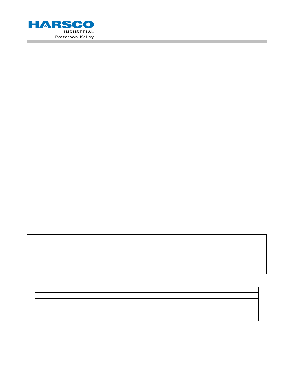
Table of US Minimum area of ventilation openings per water heater (sq inches)
MFD
MODEL
SAME FLOOR DIFF FLOORS ONE OPENING
2
/kW) of total water heater input is required.
AIR SOURCE
DIRECT
16
DUCT
DUCT
MFD
Required Combustion Air Opening
Ventilation Air Opening
Model #
Input (Btu/Hr)
in2
mm2
in2
mm2
W750MFD
750,000
25
16,129
10
6,452
W1000MFD
1,000,000
33
21,290
10
6,452
W1500MFD
1,500,000
50
32,258
10
6,452
W2000MFD
2,000,000
67
43,226
10
6,452
®
MODU-FIRE
3.5.2.2 Air Inlet Requirements – Canada (CAN/CSA B149.1)
A. Ventilation of the spac e occupied by fuel burnin g appliance(s) or equipment s hall be supplied by a ventila tion
opening at the highes t practicable point c ommunicating with the outdoors. The tota l cross sectional area of
the ventilation open ing m us t be e ither 10% of the net fr ee area r equ ired f or c om bustion air or 10 s q. i n. (6500
2
), whichever is greater.
mm
B. Use the follo wing ope ning calculat ion for MACH
supplied for a forc ed draft burner b y natural airflow from the outdoors and there is no draft regulator or draft
hood in the same space, there s hall be a permanent opening wit h a cross sectional area not les s than 1 sq.
in/ 30,000 Btu/Hr (70 m m
2
/kW) of the total rated input to the burner(s). This opening mus t not interfere with
the ventilation air opening defined in paragr a ph A.
C. Use the following opening calculation f or P-K THERMIFIC
appliances: When com bustion air is supplied for natural or fan-assis ted burners by natural airflow from the
outdoors, there shall b e a permanent openi ng with a cros s sectional area not le ss than 1 sq. in/ 700 0 Btu/Hr
(321 mm
2
/kW) up to and including 1,000,0 00 Btu/Hr plus 1 sq. in. / 14,000 Btu/Hr (155 mm2/kW ) in excess
1,000,000 Btu/Hr. T his openi ng must be e ither loca ted at or ducted t o a point not m ore than 18 in. (450 mm )
nor less than 6 in. (1 50 mm) above floor level . This opening is in add ition to the ventilatio n air opening defined in paragraph A.
D. When combustion air is supplied by natural airf low into a spac e contai ning bot h types of appl iances described
in paragraphs B and C, th e cross sectional area of the op ening shall be not less than th e sum of the cross
sectional areas for all app liances in the s pace as c alculated b y the app licabl e m ethod . This open ing is in a ddition to the ventilation air opening defined in paragraph A.
®
or MODU-FIRE® FD water heaters: When com bustion air is
Forced Draft Gas-Fired Water Heater
®
water heaters or other natural draft or fan-assist
E. When a duct is used to m eet the r equ irement for combustion air supp l y, as des cr ibe d in par agr ap hs A thr ou gh
D, above, the openin g of the duct shall be loc ate d s o t here is no pos sib il ity of cold air affec ting steam or water
piping, electrical equipment or mechanical equipment.
F. W hen combustion air is su pplied by mec hanical means, an airf low-sensing dev ice must be inst alled. It must
be wired into the pr e-ignition lim it string to prevent the burner from starting or to stop an operating burner in
case of air supply failure.
G. When all combustion air is supplied thro ugh a make-up air heater, a nd the appliance is i nter loc ked to the hea-
ter, the requirements of paragraphs A through F do not apply.
NOTICE!
1. The free area of a combustion air supply opening is calculated by deducting the blockage area of
any fixed louvers, grilles or screens from the total area of the opening.
2. Screens shall be not smaller than ¼”
3. Motorized louvers shall be interlocked with the appliance so that they are proven open prior to
main burner ignition and operation
Table of Canadian Minimum Area of Combustion and Ventilation Air Openings
17
 Loading...