

Harsco Industrial MODU-FIRE FORCED DRAFT N750, MODU-FIRE FORCED DRAFT N1500, MODU-FIRE FORCED DRAFT N1000, MODU-FIRE FORCED DRAFT N2000 Installation & Owner's Manual
C.S.A. Design-Certified
Complies with ANSI Z21.13/CSA 4.9
Gas-Fired Low Pressure Steam and Hot Water Boilers
Model #:_______ Serial #______________________
Start-Up Date:
Harsco Industrial, Patterson-Kelley
100 Burson Street
East Stroudsburg, PA 18301
Telephone: (570) 476-7261
Facsimile: (570) 476-7247
www.harscopk.com
ASME Code, Section IV
Certified by Patterson-Kelley
C.S.A. Design-Certified
Complies with ANSI Z21.13/CSA 4.9
Gas-Fired Low Pressure Steam and Hot Water Boilers
_______________________
©2010 Harsco Industrial, Patterson-Kelley
Printed: 1/21/2010

MODU-FIRE® Forced Draft Gas-Fired Boiler
1.0 INTRODUCTION .............................................................................................. 4
2.0 SAFETY ........................................................................................................... 4
2.1General ............................................................................................................................ 4
2.2Training ............................................................................................................................ 4
2.3Safety Features ................................................................................................................ 5
2.4Safety Labels ................................................................................................................... 5
2.5Safety Precautions ........................................................................................................... 6
3.0 INSTALLATION ................................................................................................ 8
3.1Receiving and Storage ..................................................................................................... 8
3.2Compliance with Codes ................................................................................................... 8
3.3Setup ................................................................................................................................ 9
3.4Electrical Connections ................................................................................................... 10
3.5Inlet Air and Exhaust Venting ......................................................................................... 12
3.6Gas Piping ...................................................................................................................... 21
3.7Boiler Water Piping ........................................................................................................ 23
3.8Burner and Ignition System ............................................................................................ 26
3.9Pre-Start Check List ....................................................................................................... 26
3.10Safety Checks ............................................................................................................. 27
3.11Boiler Operating Control ............................................................................................. 28
3.12Burner Adjustment ...................................................................................................... 30
4.0 OPERATION ...................................................................................................31
4.1General .......................................................................................................................... 31
4.2Lighting and Shut-Down Procedures ............................................................................. 31
5.0 MAINTENANCE ..............................................................................................32
5.1Maintenance and Inspection Schedule .......................................................................... 32
5.2Cleaning the Burner ....................................................................................................... 34
5.3Removing the Heat Exchanger ...................................................................................... 35
5.4After All Repairs or Maintenance ................................................................................... 35
5.5Sequence of Operation .................................................................................................. 36
5.6Troubleshooting ............................................................................................................. 37
5.7Manual Reset Error Codes – A## .................................................................................. 39
5.8Auto-reset Error Codes – E## ........................................................................................ 40
6.0 PARTS/TECHNICAL SUPPORT .....................................................................41
6.1Schematic Diagrams ...................................................................................................... 41
7.0 LIMITED WARRANTY .....................................................................................53
8.0 MODU-FIRE® FORCED DRAFT BOILER FIRE TEST REPORT ....................54
MODU-FIRE® Forced Draft Gas-Fired Boiler
!
WARNING
Improper use may
result in fire or injury.
Read instructions/safety
manual before installing,
c
1998 HCS, Inc. 800-748-0241
If the information in this manual is not followed exactly, a fire or explosion may result causing proper-
operating or servicing boiler.
Reorder No. 6020-V2WHPK
ty damage, personal injury or loss of life.
Do not store or use gasoline or other flammable vapors or liquids in the vicinity of this or any other
appliance.
Installation and service must be performed by a qualified installer, service agency, or the gas supplier.
It is essential to read, understand, and follow the recommendations of this
manual before installing, operating, or servicing this equipment.
Installation and service must be performed by a qualified and knowledgeable
individual who has been trained on the MODU-FIRE® Forced Draft boiler. The same features which
permit this boiler to achieve high-efficiency performance make it unlike most other boilers of this general size, so it is important to understand how this boiler operates.
What to do if you smell gas:
• Do not try to light any appliance.
• Do not touch any electrical switch; do not use any phone in your building.
• Immediately call your gas supplier from a neighbor's phone. Follow the gas supplier's instruc-
tions
• If you cannot reach your gas supplier, call the fire department.
3
MODU-FIRE® Forced Draft Gas-Fired Boiler
1.0 INTRODUCTION
The MODU-FIRE® Forced Draft gas-fired boiler is a revolutionary advance. Harsco Industrial, Patterson-Kelley
now combines full-modulation burner control and forced draft advances with our time-tested modular hot water
boiler design. The result is a full-modulation boiler utilizing reduced vent sizing for installation and cost efficiencies. This boiler combines the best of our earlier designs with a new generation of burner, control and operating
technology. You will achieve high part-load efficiencies – but without the complexity you might expect in this type
of high performance boiler. It is high performance made simple and dependable for years of trouble-free operation.
This manual covers installation of the MODU-FIRE® Forced Draft boilers 750MFD, 1000MFD, 1500MFD and
2000MFD. The model numbers will include a prefix and may include a suffix to indicate special features or different options. While details may differ slightly, basic operation is the same for all models. Boilers are built to operate with natural gas or propane. Check the rating label for the correct gas type and flow rate.
The boiler is only a part of the complete heating system. This boiler may be fully operational and yet, because of
poor circulation, controls, or other operating characteristics, not deliver heat to the desired location. Additional
equipment such as temperature sensors, pumps, flow switches, balancing valves and check valves will be required for satisfactory operation of any system. Harsco Industrial, Patterson-Kelley cannot be responsible for the
design or operation of such systems and a qualified engineer or contractor must be consulted.
2.0 SAFETY
2.1 G
The MODU-FIRE® Forced Draft gas-fired boiler must be:
• Installed, operated, and serviced in accordance with instructions contained in this manual and other supple-
• Installed by qualified personnel in accordance with designs prepared by qualified engineers including: struc-
• Operated and serviced in accordance with a comprehensive safety program determined and established by
• Operated and serviced by experienced, qualified, properly trained personnel in accordance with all applicable
• Installation and service must be performed by a qualified installer or service agency.
ENERAL
mental MODU-FIRE® Forced Draft boiler manuals.
tural, mechanical, electrical, and other applicable disciplines.
the customer. Do not attempt to operate or service until such a program has been established.
codes, laws, and regulations.
2.2 T
RAINING
Proper training is the best protection against accidents
It is essential to read, understand, and follow the recommendations of this manual before installing, operating, or servicing this equipment. Failure to do so could
result in serious injury, death, and/or property damage.
4
NOTICE/NOTE
MODU-FIRE® Forced Draft Gas-Fired Boiler
Operating and service personnel must be thoroughly familiar with the basic construction of the MODU-FIRE®
Forced Draft boiler, the use and locations of the controls, the operation of the boiler, adjustment of its various mechanisms, and all applicable safety precautions
ly understood, contact the Harsco Industrial, Patterson-Kelley Technical Service toll free at (877) 728-5351.
.
If any of the provisions of this manual are not fully and complete-
2.3 S
It is the responsibility of the customer to maintain the safety features of this machine, such as: guards, safety labels, safety controls, interlocks, lockout devices, etc., in place and operable.
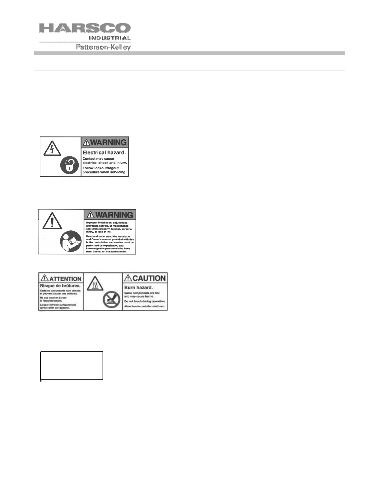
2.4 S
AFETY FEATURES
AFETY LABELS
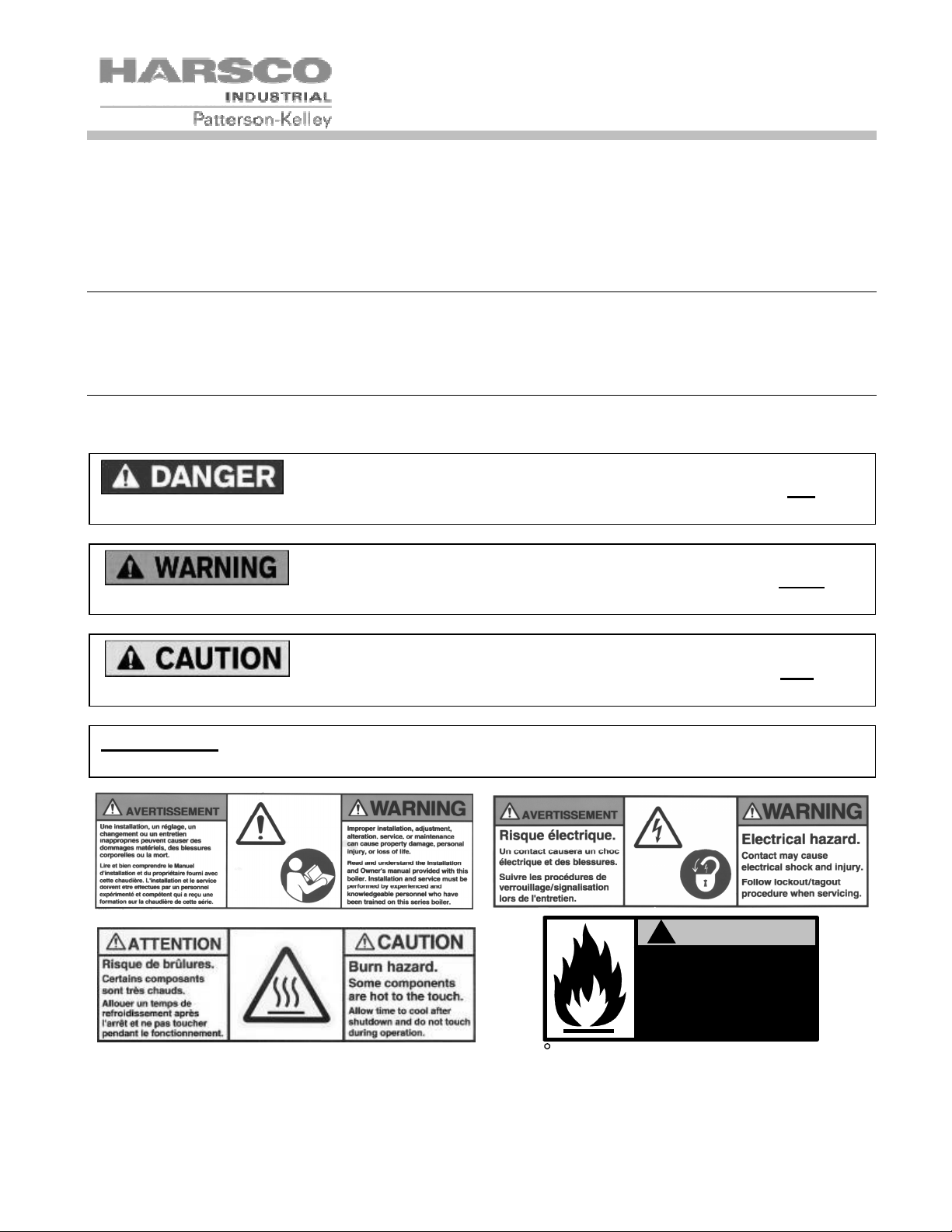
The following words are used in this manual to denote the degree of seriousness of the individual hazards.
indicates an imminently hazardous situation which, if not avoided, will result
in death or serious injury. This signal word is to be limited to the most extreme situations.
indicates a potentially hazardous situation which, if not avoided, could re-
sult in death or serious injury.
indicates a potentially hazardous situation which, if not avoided, may result
in minor or moderate injury. It may also be used to alert against unsafe practices.
- NOTICE is the preferred signal word to address practices not related to personal
injury. The safety alert symbol is not used with this signal word.
The safety labels shown above are affixed to your boiler. Although the labels are of high quality, they may become dislodged or unreadable over time. Contact Harsco Industrial, Patterson-Kelley toll-free at (877) 728-5351
for replacement labels.
!
WARNING
Improper use may
result in fire or injury.
Read instructions/safety
manual before installing,
c
1998 HCS, Inc. 800-748-0241
operating or servicing boiler.
Reorder No. 6020-V2WHPK
5
MODU-FIRE® Forced Draft Gas-Fired Boiler
2.5 S
AFETY PRECAUTIONS
Provide a suitable location for the boiler, away from normal personnel traffic, with adequate working space, adequate clearances, proper ventilation and lighting, with a structure sufficiently strong and rigid to support the weight
of the boiler, all piping, and accessories.
Proper lockout/tagout procedures must be employed whenever this unit is serviced.
2.5.1 Electrical Hazards
• Shock hazard! Properly lockout/tagout the electrical service and all
other energy sources before working on or near the machine.
• Shock hazard! Boiler is not rated for wash-down service. Do not
spray water directly on this boiler or on any electrical components.
• Electrical hazard! Do not alter wiring connections.
• Power down unit for at least 10 minutes before servicing inverter or
blower.
2.5.2 Burn, Fire, and Explosion Hazards
• Burn, fire, and explosion hazards! Installation must be in strict con-
formance to all applicable codes and standards including NFPA 54,
ANSI Z223.1 and CSA B.149.
NOTE
Make sure this union is
tight before closing cabinet
cover after servicing boiler.
c
1998 HCS, Inc. 800-748-0241
Reorder No. 8032-02NHAK
• Hazard from incorrect fuels! Possible fire, explosion, overheating,
and damage. Do not use any fuels except the design fuel for the
unit.
• Overfire hazards! High pressure in gas or propane supply could re-
sult in overfiring of other devices supplied from the same source.
• Fire and explosion hazards! Close the main gas shutoff before ser-
vicing boiler.
• Fire and explosion hazards! Do not store or use gasoline or other
flammable vapors or liquids in the vicinity of this or any other gas
fired appliance.
• Burn hazard! Possible hot surfaces. Do not touch the stack during
firing operations. Use only factory recommended vent components.
• Burn hazard! Hot fluids. Use caution. Allow boiler to cool before
servicing or draining boiler.
• Fire and explosion hazards! Use caution when servicing burner or
heat exchanger. Fuel may linger in the combustion chamber, vent
lines, or elsewhere.
• Gas leak hazard! Make sure all connections to main burner are tight
when reassembling the burner.
6
MODU-FIRE® Forced Draft Gas-Fired Boiler
• Gas leak hazard! All threaded gas connections must be made using
a pipe compound that is resistant to liquefied petroleum. Do not use
Teflon tape on threaded gas piping.
• Gas leak hazard! Check entire gas train for leaks after installation. If
there is a smell of gas, shut down the boiler, close all gas valves and
obtain immediate assistance from factory-trained personnel and/or
your local fire department.
• Overfire hazard! Possible fire and explosion from excess gas pres-
sure. Make sure that gas inlet pressure does not exceed 14 inches
W.C. to the boiler main gas valve.
• Overfire hazard! Possible fire and explosion. Possible malfunction
of regulators and/or gas valves. Maintain all gas train components in
good condition. Do not alter wiring connections. Annual inspection
by factory-trained personnel for proper set-up and operation is recommended.
• Overfire and underfire hazards! Possible fire, explosion, overheating,
and component failure. Do not attempt to adjust firing rate of the boiler. The firing rate must be adjusted only by factory-trained personnel.
2.5.3 Crush Hazards
• Lifting hazards! Use properly rated lifting
equipment to lift and position the boiler.
The load is unbalanced. Test balance before lifting 3 ft. above the floor. Do not allow personnel beneath the lifted load.
Refer to approximate weights in the ta-
General Warning
ble:
• Bump hazard from overhead piping. Install piping with adequate vertical clearance.
2.5.4 Chemical Hazards
• Chemical hazards from cleaning products. Use caution when cleaning the system. The
use of professional assistance is recommended. Use safe procedures for the disposal of
all cleaning solutions.
General Warning
2.5.5 Pressure Hazards
• Pressure hazard! Hot fluids. Install isolation valves on boiler water inlet and outlet.
Make sure isolation valves are closed before servicing boiler.
Boiler Size Weight in Pounds
750,000 Btu 745
1,000,000 Btu 745
1,500,000 Btu 915
2,000,000 Btu 930
General Warning
• Pressure hazard! Hot fluids. Test safety relief valve bimonthly for proper operation. Do
not operate boiler with faulty relief valve.
7
MODU-FIRE® Forced Draft Gas-Fired Boiler
2.5.6 General Hazards
• Tripping hazard! Do not install piping on floor surfaces. Maintain clear path around boi-
ler.
• Slip and fall hazard! Use drip pan to catch water while draining the boiler. Maintain dry
floor surfaces.
• Slip and fall hazard! Through-the-wall vents shall not terminate over public walkways or
General Warning
over an area where condensate or vapor could create a nuisance or hazard.
• Fall hazard! Do not stand on any part of the boiler.
• Catch hazard! Do not wear rings, jewelry, long hair, loose clothing while working on the
boiler.
3.0 INSTALLATION
Installation and service must be performed by a qualified installer or service
agency.
3.1 R
ECEIVING AND STORAGE
3.1.1 Initial Inspection
Upon receiving the boiler, inspect it for signs of shipping damage. Since some damage may be hidden, we
recommend unpacking the boiler, removing the top, front, and side covers and inspect the boiler. Verify that the
total number of pieces shown on the packing slip agrees with those actually received.
NOTICE! Note any damage, suspected potential damage, or shortage of materials on the freight bill
and immediately notify the carrier. File all claims for shortage or damage with the carrier. Claims for
hidden damages must be filed with your carrier within 7 days. The boiler carton is equipped with a
“Tip (N) Tell”. If "Tip (N) Tell” arrow point is blue, that indicates that the package has been on its
side or tipped over in transit.
3.1.2 Storage Prior to Installation
If the boiler is not installed immediately, it must be stored in a location adequately protected from the weather and
freezing conditions, preferably indoors. If this is not possible, then it should remain in the shipping container and
be covered by a tarpaulin or other waterproof covering.
NOTICE! Controls and other equipment that are damaged or fail due to weather exposure are not
covered by warranty.
3.2 C
The MODU-FIRE® Forced Draft boiler with standard components and many options complies with American National Standard/CSA Standard ANSI Z21.13/CSA 4.9, Gas-Fired Low Pressure Steam and Hot Water Boilers, latest edition. The heat exchanger is constructed and stamped in accordance with ASME Boiler and Pressure Vessel Code, Section IV for 160 psig maximum operating pressure and/or 250º F maximum operating temperature.
OMPLIANCE WITH CODES
8
B
D
MODU-FIRE® Forced Draft Gas-Fired Boiler
Installation of the boiler must conform to all the requirements of all national, state and local codes established by
the authorities having jurisdiction or, in the absence of such requirements, in the U.S. to the National Fuel Gas
Code, ANSI Z223.1/NFPA 54, latest edition. In Canada, the equipment shall be installed in accordance with the
current Installation Code for Gas Burning Appliances and Equipment, CSA-B.149.1, and applicable Provincial
Regulations for the class, which should be carefully followed in all cases. Authorities having jurisdiction should be
consulted before installations are made.
Where required by local codes, the installation must conform to American Society of Mechanical Engineers Safety
Code for Controls and Safety Devices for Automatically Fired Boilers (ASME CSD-1).
In the Commonwealth of Massachusetts, (a) this unit must be installed by a licensed pipe fitter / plumber, (b) field
installed gas cocks must be “T” handle type, (c) piping of condensate shall conform to the State Plumbing Code,
and (d) refer to the Massachusetts supplement for further details.
.
3.3 S
ETUP
3.3.1 Foundation
Provide a firm, level foundation, preferably of concrete.
NOTICE! The boiler may be installed on a combustible floor; however, the boiler must never be installed on carpeting.
NOTICE! This boiler is certified for indoor installation only.
3.3.2 Placement
The boiler must be level and upright to function properly. Use shims or other approved structural devices to properly level boiler.
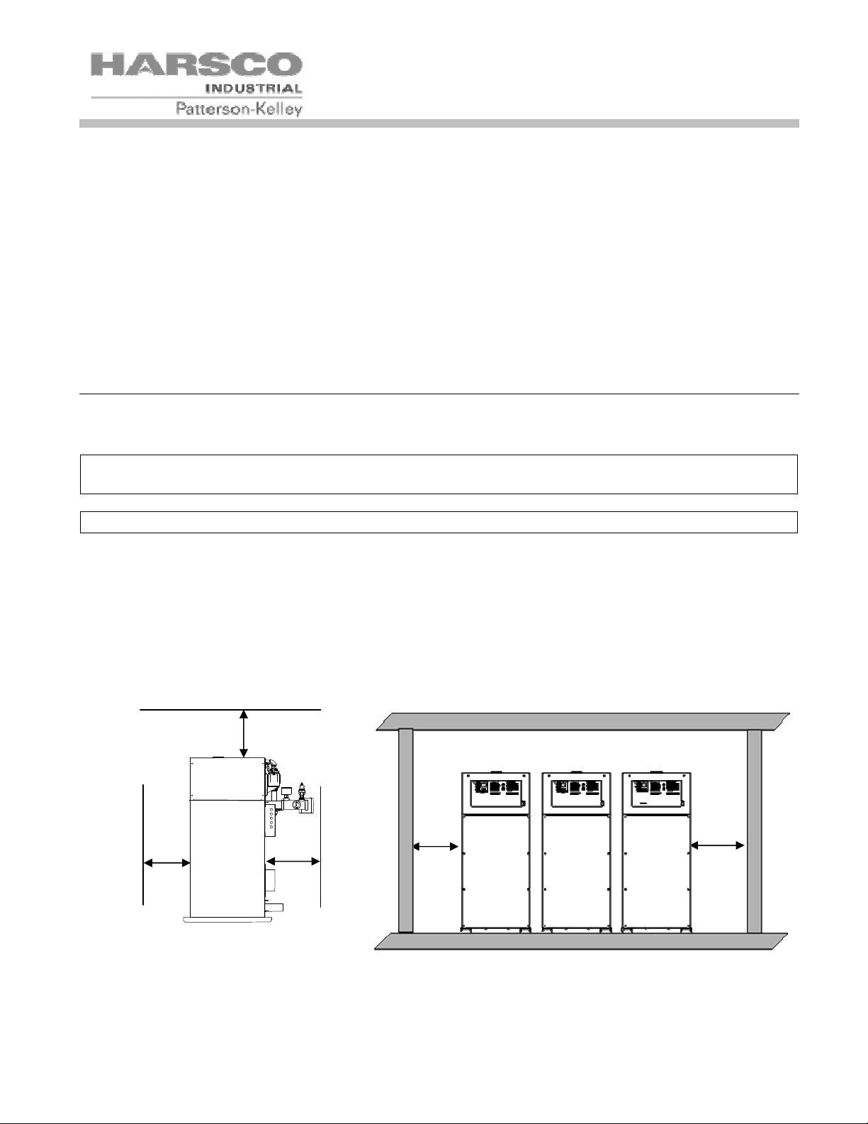
3.3.3 Installation Clearances
If the boiler is to be installed near combustible surfaces, six (6”) inches minimum clearance to the combustible
surface must be maintained. Failure to provide for the service access clearances, even with non-combustible surfaces, may cause future problems servicing the boiler. The boiler must be installed in a space large in comparison to the boiler as described in the National Fuel Gas Code, NFPA 54/ANSI Z223.1, latest edition.
C
A
D
Clearances from Adjacent Walls, Side Clearances for a Row of Boilers
Ceiling and Obstructions
9
MODU-FIRE® Forced Draft Gas-Fired Boiler
Type of Surface Dimensions (inches)
A B C† D
CSA Minimum Clearances to Combustibles 24 24* 24 24
Recommended Service Clearances 30 24* 24 24**
† “C" dimension includes clearance to remove the burner. Do not put pipes, ducts, etc. in this area above the boiler.
*CSA minimum. Actual clearance depends upon venting requirements.
** Service access need be only on one side of a boiler or row of boilers. Boilers may be installed immediately adjacent to each
other. However, Harsco Industrial, Patterson-Kelley recommends this clearance between each boiler when there is insufficient access at the rear to allow for service and adjustment.
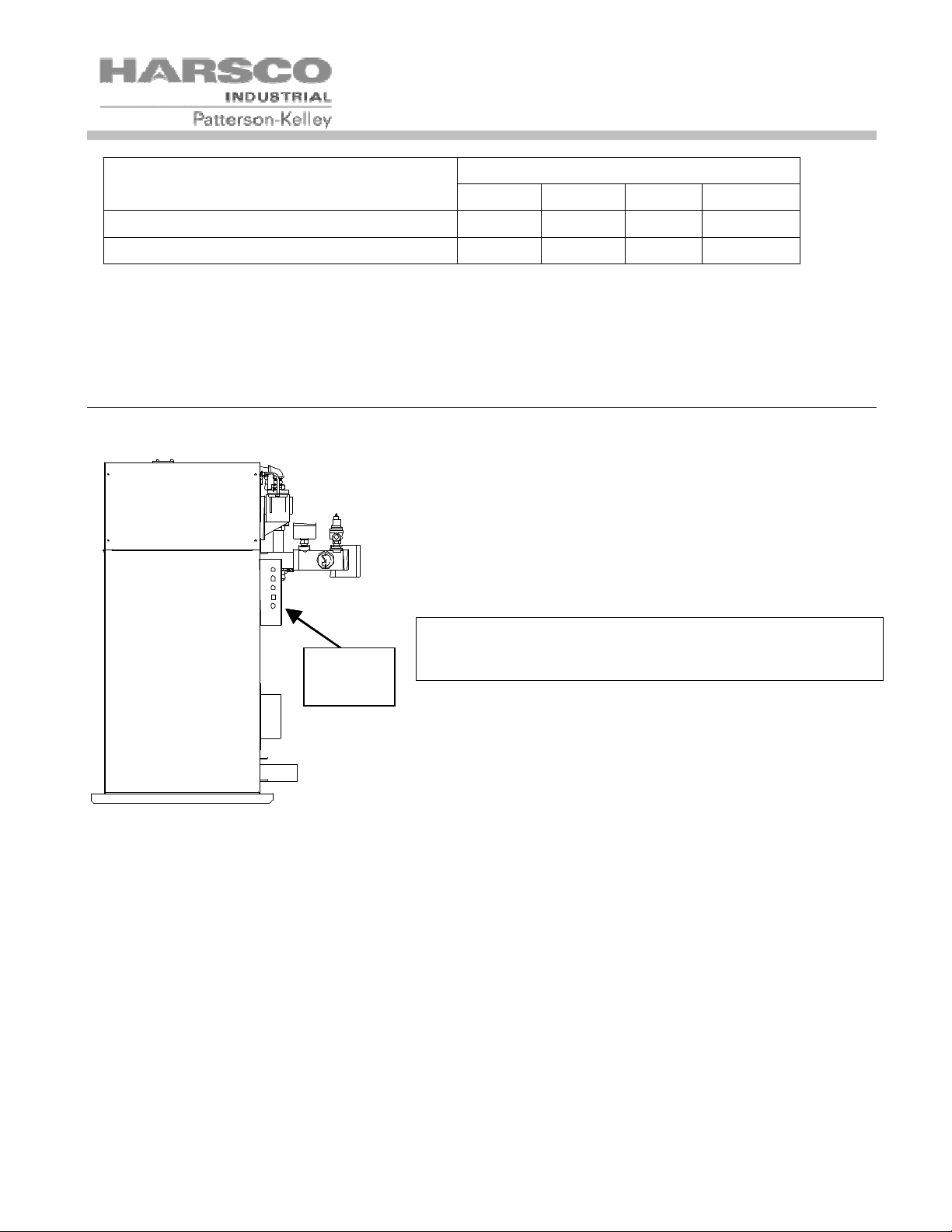
3.4 E
All field wiring connections for power and controls are in the junction box on the back of the boiler.
LECTRICAL CONNECTIONS
The boiler wiring label is attached to the inside front door of the
boiler. An external electrical disconnect (not supplied with the
boiler) with adequate overload protection is required. The boiler
must be grounded in accordance with local codes or in the absence of such requirements, in the U.S. with National Electrical
Codes, ANSI/NFPA No. 70 latest edition and in Canada, wire according to the current Canadian Electrical Code.
NOTICE! A dedicated earth ground (green wire) is re-
Electrical
Connections
quired to avoid nuisance shutdowns. It is also important
that proper polarity be maintained.
The junction box at the rear of the boiler contains terminal strips
for power and control connections. A detailed schematic of the
connections is shown in 6.1.7. These connections are as follows:
3.4.1 High Voltage (HV) Terminal Block
The boiler power circuit requires 240 volts, single phase, 60 hertz, with a dedicated neutral and ground as labeled.
The voltage between L1 (HV-1) and L2 (HV-2) must be approximately 230V, while the voltage from each line to
the neutral (HV-3) must be approximately 120V AC. Electrical service must be rated for 17 amps minimum.
Before starting the boiler, check to ensure that the proper voltage and amperage are connected to the boiler and
that the boiler is connected to a suitable fused disconnect switch or circuit breaker. There must be less than 1.0V
from Neutral (HV-3) to Ground (HV-10)
120VAC Switched Output- This contact closes when the boiler is switched on. This provides 120VAC 5Amp
service to HV12 and HV13. The neutral for this circuit is provided on HV4 and HV5. When the boiler is switched
off, these terminals are switched off as well.
3 Way Valve- This output is normally energized, maintaining the three way valve in the position to provide heat to
the building. The Domestic Hot Water (DHW) call for heat de-energizes this circuit, causing the 3 way valve to
10
MODU-FIRE® Forced Draft Gas-Fired Boiler
drive to the position to provide heat to the DHW loop. This output provides 120VAC 0.5Amp service to HV14.
The neutral for this circuit is provided on HV 6.
DHW Pump Relay w/Delay Off - This output is enabled when there is a call for DHW. When the call for heat is
removed, the output remains enabled for a predetermined period of time. The time delay is adjustable through the
ENVI™ control system. This output provides 120VAC 0.5Amp service to HV15. The neutral for this circuit is
provided on HV 7.
Circ Pump Relay w/Delay Off - This output is enabled when there is a call for heat. When the call for heat is
removed, the output remains enabled for a predetermined period of time. The time delay is adjustable through the
ENVI™ control system. This output provides 120VAC 0.5Amp service to HV16. The neutral for this circuit is
provided on HV 8.
Damper Relay - This output is enabled when the call for heat is enabled. This output provides 120VAC service
to HV17. The neutral for this circuit is provided on HV 9. This circuit is for pilot duty only (less than 1 amp).
Master Alarm Relay – This contact closes in the event of an alarm output from the boiler control, connecting
HV18 and HV19.
Flame Detected Relay – This contact closes whenever the boiler is firing, connecting HV20 and HV21.
3.4.2 Low Voltage (LV) Terminal Block
Enable/Disable– Use for boiler enable. Closing this circuit allows the boiler to run. Opening this circuit prevents
the boiler from running, provided the remote/local enable switch is in the remote position. This circuit is energized
by the boiler. It has a 24VAC potential. Devices connected to these terminals must be rated for 24VAC.
The remote/local enable switch bypasses the Enable/Disable (LV1 to LV2)
when in the local position. Do not connect safety devices into the Enable/Disable circuit.
Auxiliary Low Water Cutoff – These terminals are used for connection of a secondary low water cutoff used in
the system. This circuit is energized by the boiler. It has a 5V potential. Devices connected to these terminals
must be rated for 5V.
Start Interlock - Use for attachment of an additional field safety device to the boiler control circuit. Closing this
circuit allows the boiler to run. Opening this circuit prevents the boiler from running. This circuit is energized by
the boiler with a 5V potential. Devices connected to these terminals must be rated for 5V.
Outdoor Temp Sensor – LV7 and LV8 are connected to the outdoor temperature sensor. The temperature
control must be programmed to run an outdoor air schedule. The outdoor air sensor and programming help are
available from the ENVI™ Advanced User’s Guide (ENVI™ 09) or from your local Harsco Industrial, PattersonKelley Representative. This circuit is energized by the boiler with a 5V potential. The temperature sensor must be
a NTC having 12k@25°C.
DHW Stat/Sensor – LV9 and LV10 are connected to the DHW temperature sensor or thermostat. This circuit is
energized by the boiler with a 5V potential. The temperature sensor must be a NTC having 12k@25°C.
Header Temp Sensor – LV11 and LV12 are connected to the header temperature sensor. This circuit is
energized by the boiler with a 5V potential. The temperature sensor must be a NTC having 12k@25°C.
11
MODU-FIRE® Forced Draft Gas-Fired Boiler
DHW Flow Switch – LV13 is energized by the boiler with a 5V potential. This circuit connects through a flow
switch on the domestic side of a domestic hot water system. The flow switch should close upon flow to provide a
closed circuit back to LV14.
Analog Input– Remote signal for controlling the boiler. The boiler can be operated in a remote setpoint or a
remote firing rate control mode. Input 0-10VDC signal only. The temperature control must be programmed to run
with the analog input.
MODBUS® – LV19 and LV20 are used for connecting a MODBUS® building management system. (See the
ENVI™ control Advanced Users Guide for more information)
Cascade – LV21 and LV22 are used to connect between boilers that are part of a Master/Member Network. Up to
24 boilers may be connected together. (See the ENVI™ control Advanced Users Guide for more information)
3.5 I
NLET AIR AND EXHAUST VENTING
3.5.1 Applicable Codes & Standards
CODES
United States:
NFPA 54/ANSI Z223.1 National Fuel Gas Code
NFPA/ANSI 211 Chimneys, Fireplaces, Vents and Solid Fuel Burning Appliances
Canada
CAN/CSA B149.1 Installation Codes for Gas Burning Equipment
STANDARDS
UL 1738 Venting Systems for Gas-Burning Appliances, Categories II, III, and IV
These codes and standards contain information for the venting of gas fired appliances, including, but not limited to
vent sizing, location, clearance to combustibles, and safe installation practices. The installation must comply with
both the above Federal Codes and with state, provincial and local codes.
Design and installation of venting systems should be done only by qualified
and knowledgeable venting systems personnel and in accordance with vent system manufacturer’s
installation instructions. Installing a boiler or vent system using improper installation methods or
materials can result in serious injury or death due to fire or asphyxiation.
Before connecting a boiler to a venting system, it must be determined
whether the boiler is to be installed in a conventional or direct vent configuration. In the US, provisions for combustion and ventilation air must be in accordance with NFPA 54/ANSI Z223.1, National
Fuel Gas Code, latest edition, or applicable provisions of the local building codes. In Canada, combustion and ventilation air openings shall comply with CAN/CSA B-149.1 Natural Gas and Propane
Installation Code.
12

MODU-FIRE® Forced Draft Gas-Fired Boiler
For correct installation of vent system, read all of these instructions and refer to vent manufacturer’s instructions.
Failure to use a proper vent system (types and materials), as described in this manual will void the
boiler warranty and may result in rapid deterioration of the venting system, creating a health or life
safety hazard.
Faulty vent installation can allow toxic fumes to be released into living areas. This may cause property damage, serious bodily injury or death.
3.5.1.1 Gas Vent Categories
Several codes and standards have categorized appliances in accordance with the flue gas temperature and pressure produced by the appliance. Categories are defined as follows:
• Category I An appliance that operates with a non-positive vent static pressure and with a vent tempera-
ture that avoids excessive condensate production in the vent.
• Category II An appliance that operates with a non-positive vent static pressure and with a vent tempera-
ture that may cause excessive condensate production in the vent.
• Category III An appliance that operates with a positive vent static pressure and with a vent temperature
that avoids excessive condensate production in the vent.
• Category IV An appliance that operates with a positive vent static pressure and with a vent temperature
that may cause excessive condensate production in the vent.
• Direct Vent An appliance that is constructed and installed so that all air for combustion is derived directly
from outdoors and all flue gases are discharged to the outdoors.
3.5.1.2 Venting Materials for Flue/Exhaust Systems
MODU-FIRE® Forced Draft boilers are Category IV appliances, which vent with a positive exhaust pressure and
with a temperature that is likely to cause condensation in the vent. Therefore, any venting system used with the
MODU-FIRE® Forced Draft boiler must comply with the requirements for Category IV venting systems as specified in the latest edition of NFPA 54/ANSI Z223.1 in the US or the latest edition of CAN/CSA B-149.1 in Canada.
The venting materials listed below are intended for the venting of gas burning appliances only. Do not use these venting materials for venting liquid or solid fuel (such as oil, kerosene, wood or coal) appliances.
Maintain clearances to combustibles as listed in the vent manufacturer’s installation instructions or as
set forth in the codes and standards listed in this section.
Do not use these vent pipes for incinerators of any sort.
3.5.2 Combustion Air
Combustion air must be free from dust, lint, etc. The presence of such materials in the air supplied to the burner
could cause nuisance "Low Air" shutdowns or premature burner failure. The boiler should not be operated during
construction while the possibility of drywall dust, demolition dust, etc. exists.
The combustion air supply must be completely free of chemical fumes which may be corrosive when burned in the
boiler. Common chemicals which must be avoided are fluorocarbons and other halogenated compounds, most
commonly present as refrigerants or solvents, such as freon, trichloroethylene, perchlorethylene, chlorine, etc.
13

MODU-FIRE® Forced Draft Gas-Fired Boiler
These chemicals, when burned, form acids which quickly attack the boiler and the boiler stack. The result is improper combustion and premature boiler failure.
Under no circumstances shall the boiler room ever be under a negative
pressure. Particular care should be taken when exhaust fans, compressors, air-handling units or other equipment may rob air from the boiler. Note that this equipment might be in rooms other than the
boiler room.
3.5.2.1 Air Inlet Requirements – United States (NFPA 54/ANSI Z223.1 & NFPA/ANSI 211)
When air is supplied from inside the building, the total required volume shall be the sum of the required volume for
all the appliances located in the mechanical room. Adjacent rooms furnished with fixed openings communicating
directly with the mechanical room are considered part of the required volume. The minimum volume is 50 ft3 per
1000 Btu/hr (4.8 m3/kW) of installed appliance input capacity.
Openings used to connect indoor spaces to obtain the required minimum volume shall be sized as follows:
• When rooms are on the same floor, each opening shall have an area equal to 1 square inch for each
1000 Btu/hr (2200 mm2 / kW) of installed appliance input capacity, but not less than 100 square inches.
One opening should commence less than 12 inches above the floor and the other less than 12 inches below the ceiling. The minimum dimension of air openings shall be 3 inches.
• When rooms are on different floors, each opening shall have an area equal to 2 square inches for each
1000 Btu/hr (4400 mm2 / kW) of installed appliance input capacity.
When combustion air is supplied from outside the building, the boiler room shall be provided with one or two openings to ensure adequate combustion air and proper ventilation.
When using one permanent opening, the opening shall commence within 12 inches of the ceiling and shall communicate directly with the outdoors or through a vertical or horizontal duct that communicates to the outdoors.
• Minimum free area of the opening is 1 square inch for each 3000 Btu/hr (700 mm2 / kW) of installed ap-
pliance input capacity, and
• Not less than the sum of the areas of all vent connectors in the room.
When using two permanent openings, one opening shall commence within 12 inches above the floor and the other within 12 inches below the ceiling, preferably on opposite walls. The openings shall communicate directly, or
by way of ducts, with free outdoor air. The minimum net free area of the openings shall be calculated in accordance with the following:
• When air is taken directly from outside the building, each opening (minimum of two, as outlined above), 1
square inch for each 4,000 Btu per hour (550 mm2/kW) of total boiler input is required.
• When air is taken from the outdoors through a vertical duct into the mechanical room, 1 square inch per
4,000 Btu per hour (550 mm2/kW) of total boiler input is required.
• When air is taken from the outdoors through a horizontal duct into the mechanical room, 1 square inch per
2,000 Btu per hour (1100 mm2/kW) of total boiler input is required.
NOTICE!
1. The required size of openings for combustion and ventilation air shall be based on the net free
area of the opening.
2. Screens shall be not smaller than ¼”
3. Motorized louvers shall be interlocked with the appliance so that they are proven open prior to
main burner ignition and operation.
14
MODU-FIRE® Forced Draft Gas-Fired Boiler
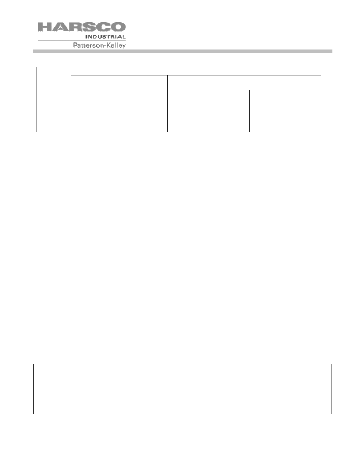
Table of US Minimum area of ventilation openings per boiler (sq inches)
AIR SOURCE
INDOOR AIR SUPPLY OUTDOOR AIR SUPPLY
TWO OPENINGS
MFD
MODEL
N750 750 1500 250 188 188 375
N1000 1000 2000 333 250 250 500
N1500 1500 3000 500 375 375 750
N2000 2000 4000 667 500 500 1000
3.5.2.2 Air Inlet Requirements – Canada (CAN/CSA B149.1)
A. Ventilation of the space occupied by fuel burning appliance(s) or equipment shall be supplied by a ventilation
opening at the highest practicable point communicating with the outdoors. The total cross sectional area of
the ventilation opening must be either 10% of the net free area required for combustion air or 10 sq. in. (6500
mm2), whichever is greater.
B. Use the following opening calculation for MACH® or MODU-FIRE® FD boilers: When combustion air is sup-
plied for a forced draft burner by natural airflow from the outdoors and there is no draft regulator or draft hood
in the same space, there shall be a permanent opening with a cross sectional area not less than 1 sq. in/
30,000 Btu/Hr (70 mm2/kW) of the total rated input to the burner(s). This opening must not interfere with the
ventilation air opening defined in paragraph A.
SAME FLOOR DIFF FLOORS ONE OPENING
DIRECT
VERT
DUCT
HORIZ
DUCT
C. Use the following opening calculation for P-K THERMIFIC® boilers or other natural draft or fan-assist ap-
pliances: When combustion air is supplied for natural or fan-assisted burners by natural airflow from the outdoors, there shall be a permanent opening with a cross sectional area not less than 1 sq. in/ 7000 Btu/Hr (321
mm2/kW) up to and including 1,000,000 Btu/Hr plus 1 sq. in. / 14,000 Btu/Hr (155 mm2/kW) in excess
1,000,000 Btu/Hr. This opening must be either located at or ducted to a point not more than 18 in. (450 mm)
nor less than 6 in. (150 mm) above floor level. This opening is in addition to the ventilation air opening defined in paragraph A.
D. When combustion air is supplied by natural airflow into a space containing both types of appliances described
in paragraphs B and C, the cross sectional area of the opening shall be not less than the sum of the cross
sectional areas for all appliances in the space as calculated by the applicable method . This opening is in addition to the ventilation air opening defined in paragraph A.
E. When a duct is used to meet the requirement for combustion air supply, as described in paragraphs A through
D, above, the opening of the duct shall be located so there is no possibility of cold air affecting steam or water
piping, electrical equipment or mechanical equipment.
F. When combustion air is supplied by mechanical means, an airflow-sensing device must be installed. It must
be wired into the pre-ignition limit string to prevent the burner from starting or to stop an operating burner in
case of air supply failure.
G. When all combustion air is supplied through a make-up air heater, and the appliance is interlocked to the hea-
ter, the requirements of paragraphs A through F do not apply.
NOTICE!
1. The free area of a combustion air supply opening is calculated by deducting the blockage area of
any fixed louvers, grilles or screens from the total area of the opening.
2. Screens shall be not smaller than ¼”
3. Motorized louvers shall be interlocked with the appliance so that they are proven open prior to
main burner ignition and operation
15
MODU-FIRE® Forced Draft Gas-Fired Boiler
Table of Canadian Minimum Area of Combustion and Ventilation Air Openings
MFD Required Combustion Air Opening Ventilation Air Opening
Model # Input (Btu/Hr) in2 mm2 in2 mm2
N750 750,000 25 16,129 10 6,452
N1000 1,000,000 33 21,290 10 6,452
N1500 1,500,000 50 32,258 10 6,452
N2000 2,000,000 67 43,226 10 6,452
3.5.3 Flue Venting
This boiler is not certified for use with Type "B" vent nor with any type of plastic venting.
This boiler is a Category IV appliance (condensing – positive pressure) as it is defined in ANSI Z21.13/CSA 4.9,
latest edition. The vent material must be as described in section 3.5.1.2. The exhaust vent can be run horizontally or vertically.
Vent installations shall be in accordance with NFPA54/ANSI Z223.1, the National Fuel Gas Code, or CAN/CSAB149.1, the Natural Gas and Propane Installation Code, or applicable provisions of the local building codes.
Do not use a barometric damper with this boiler. This is a positive pres-
sure system. Flue gases may leak into the room.
This equipment MUST NOT be used with a heat actuated automatic vent
damper.
All boiler venting systems should be designed by a qualified venting professional experienced in venting system design. The information contained herein should be used as a
guide only and is not intended to be used in lieu of qualified technical expertise.
3.5.3.1 Vent Sizing
The vent must be sized in accordance with the ASHRAE Systems and Equipment handbook, Chapter 30 or according to the vent manufacturer’s recommendations. When using manufactured venting systems, consult your
vent supplier for correct sizing and structural support requirements.
The vent must be sized according to the vent manufacturer’s recommendations.
supplier for correct sizing and structural support requirements.
Design calculations for a single boiler/single stack installation should be based on a positive pressure at the flue
collar of 1.0” w.c. (not to exceed 2.0” w.c.) with a stack temperature of 325° F (gross) and a CO
(natural gas) or 9.9% (propane).
The vent should be designed to provide positive pressure at the flue collar at all firing rates.
Additional care must be used with sidewall venting as the exhaust velocity is high and the exhaust gas plume may
extend significantly beyond the termination.
Consult your vent
level of 8.5%
2
16
MODU-FIRE® Forced Draft Gas-Fired Boiler
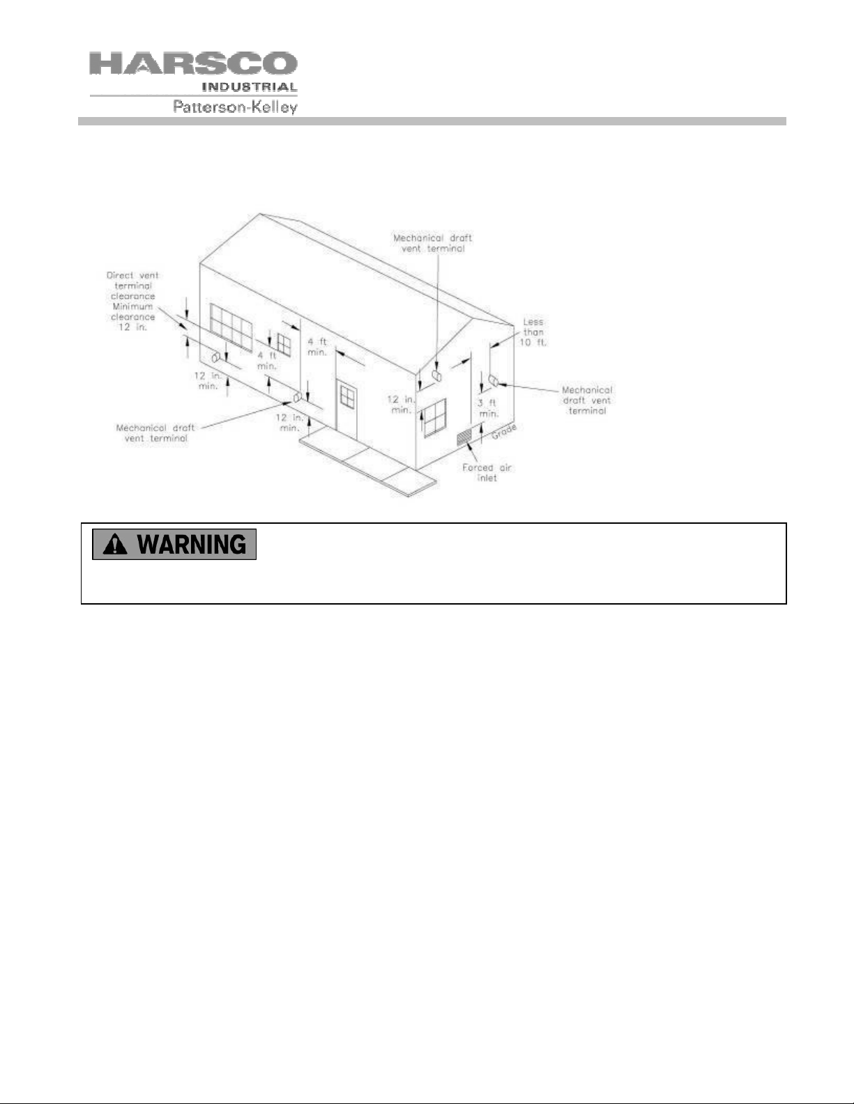
3.5.3.2 Required Clearances
Provide clearances between combustion air intake, exhaust vent, roof and wall surfaces, doors and window, and
snow line. Refer to Figure below: Termination Clearances – Forced Draft and Direct Vent Installations.
Do not locate intake or exhaust terminations directly above a walkway;
dripping of condensation can cause icing of the walking surface. Maintain a minimum clearance of 4
ft (1.22 m) horizontally from any electric or gas meter, regulator or relief equipment.
3.5.3.2.1 Conventional Vent Systems
The following termination clearance requirements are for conventional, non-direct vent installations.
• The vent system shall terminate at least 3 ft above a forced air inlet that is within 10 feet horizontally.
• The vent system shall terminate at least 4 ft below, 4 ft horizontally from or 1 ft above any door, operable
window or gravity inlet into any building. The bottom of the vent terminal shall be at least 12 in. above
grade or highest expected snow line (if applicable).
• Through the wall terminations shall not terminate over public walkways or over an area where condensate
or vapor could create a nuisance or hazard or could be detrimental to the operation of regulators, relief
valves or other equipment.
3.5.3.2.2 Direct Vent (Sealed Combustion) Systems
• The vent terminal shall be located at least 12 in. from any air opening into a building. The bottom of the
vent terminal shall be at least 12 in. above grade. Both the vent and air intake terminals must be at least
12 in. above the highest expected snow line.
• Through the wall terminations shall not terminate over public walkways or over an area where condensate
or vapor could create a nuisance or hazard or could be detrimental to the operation of regulators, relief
valves or other equipment.
• When multiple direct vent appliances are adjacent, the exhaust must terminate at least 10 feet horizontally
or three feet vertically from the air intake of another appliance.
17
 Loading...