

Harsco Industrial ENVI Advanced User's Manual
ENVI® Control
Rev. 2. (12/19/2014)
Software versions 112E, BD71,
49A7, 79F2, 8C51,1043, 9820
ENVI® Boiler Controller
Advanced User’s Guide
Installation Date: _______________________
Harsco Industrial, Patterson-Kelley
155 Burson Street
East Stroudsburg, PA 18301
Telephone: (877) 728-5351
Facsimile: (570) 476-7247
www.harscopk.com
© 2011 Harsco Industrial, Patterson-Kelley

2
ENVI® Control
1.0 ENVI® BOILER CONTROL ...................................................................................................................... 3
1.0 Operation of the ENVI Control ...................................................................................................................................... 5
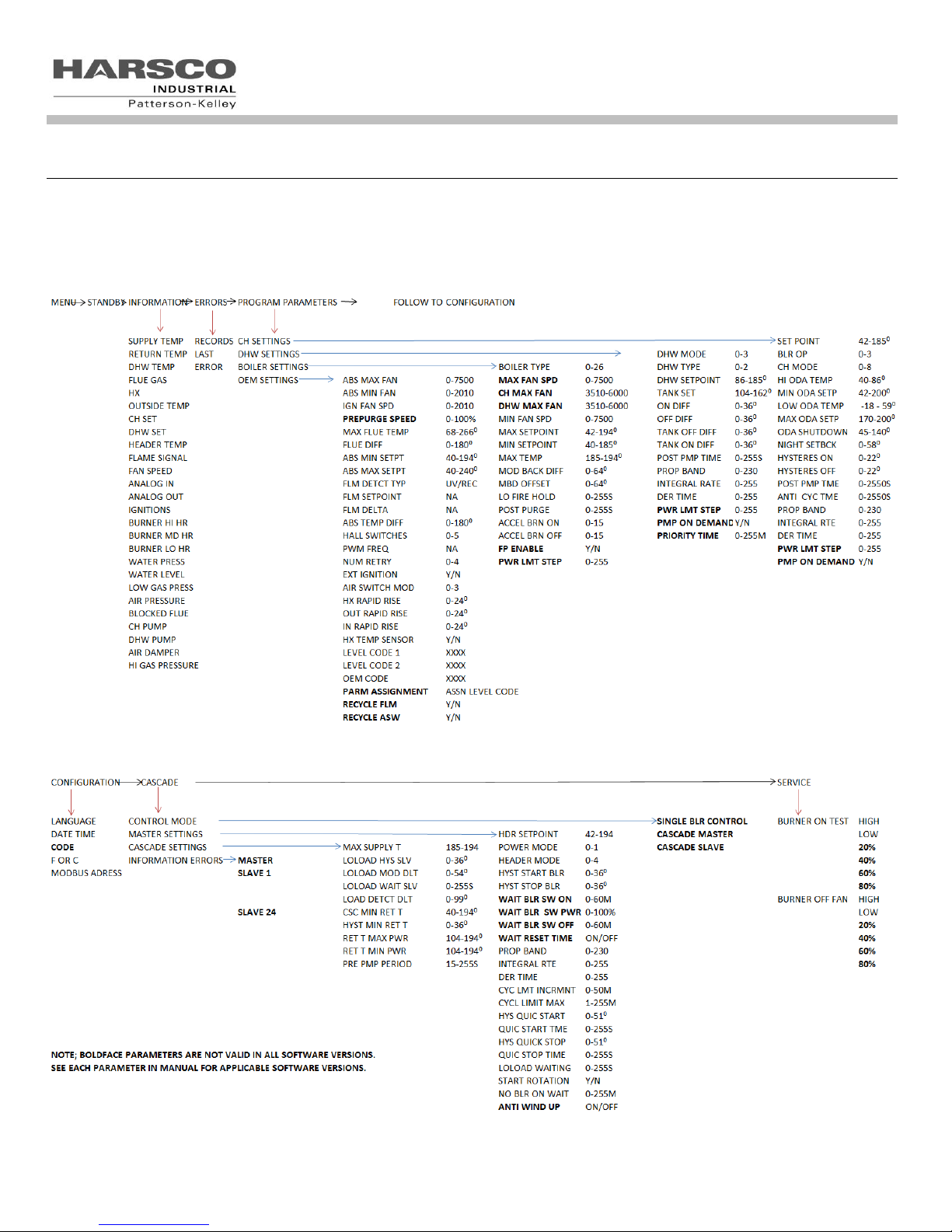
1.1 ENVI® control flow chart ................................................................................................................................................ 6
1.2 Menu Screen ................................................................................................................................................................. 7
1.3 Boiler Status Screen ..................................................................................................................................................... 7
1.4 Information Menu .......................................................................................................................................................... 8
1.5 Errors Menu ................................................................................................................................................................ 10
1.6 Program Parameters Menu ......................................................................................................................................... 11
1.6.1 Initial Setup of the Control .................................................................................................................................. 11
1.6.2 CH Settings .......................................................................................................................................................... 12
1.6.2 CH Modes ........................................................................................................................................................... 14
1.6.3 DHW Settings ..................................................................................................................................................... 20
1.6.4 DHW Modes ........................................................................................................................................................ 21
1.6.5 Boiler Settings ..................................................................................................................................................... 22
1.6.6 OEM SETTINGS ................................................................................................................................................. 23
1.7 Configuration Menu: .................................................................................................................................................... 23
1.8 CASCADE MENU: ...................................................................................................................................................... 24
1.8.1 Cascade setup .................................................................................................................................................... 24
1.8.2 Control Mode ...................................................................................................................................................... 24
1.8.3 Master Settings ................................................................................................................................................... 25
1.8.4 Master Modes ..................................................................................................................................................... 26
1.8.5 Cascade Settings ................................................................................................................................................ 33
1.9 Service Menu: ............................................................................................................................................................. 38
2.0 TROUBLESHOOTING ........................................................................................................................... 39
2.0.1 Troubleshooting Table ........................................................................................................................................ 39
2.0.1 The Loss of Power .............................................................................................................................................. 39
3.0 APPENDIX –MODBUS® INTERFACE .................................................................................................... 43
3.0.1 Descriptions of MODBUS® Register Map ........................................................................................................... 44
3.0.2 Boiler State ......................................................................................................................................................... 45
3.0.3 Information Byte .................................................................................................................................................. 45
3.0.4 Sequence Byte .................................................................................................................................................... 45
4.0 MODBUS CONFIGURATION ................................................................................................................. 48

3
26-0000-0507
Outdoor air sensor
BP-0000-0279
Well and sensor for header and DHW applications ENVI® Control
23-0000-0539
Surface mount strap on sensor kit for header or DHW applications ENVI® Control
BP-0000-0480
Kit, 12” brass thermowell, tank temperature sensor, DHW applications ENVI® Control
10-0510-0642
Dual element immersion sensor
86-8350-0800
Switch, flow switch
10-0000-1209
SW,THERMO,100-200F,HONEYWELL_L6008A1242
23-0000-0233
THERMOWELL, ½” NPT
ENVI® Control
1.0 ENVI
The ENVI® boiler control consists of 3 components and is an intelligent control system with advanced features such as textbased display, MODBUS® communication capabilities, and boiler sequencing. Firing rate and setpoint can be controlled
via an external 0-10VDC analog control signal. Errors are date and time stamped, and the control records burner run time
at various operating points. A single integral control for temperature control, flame safeguard, firing rate control, blocked
flue protection, outdoor air reset, freeze protection, built-in cascade sequencing and more. Throughout this manual and in
the ENVI® controller the term “Hysteresis” is used with the meaning of “Differential”.
The ENVI® control is capable of accepting building management control via 0-10VDC and MODBUS®. Other languages
require the use of a Protocol converter which is also available separately from your Patterson-Kelley representative.
®
BOILER CONTROL
ENVI® APPLICATION
Note: The ENVI® control is capable of running the boiler on its own without any external control hardware or accessories.
However, certain applications warrant the purchase and installation of separate sensors such as:
Optional flow switch: (necessary in some DHW applications)
Optional aquastat: (necessary in some DHW applications)
These optional sensors will enhance the performance of the ENVI® control and may be necessary to sense the locations
needed for some applications to perform properly.
4
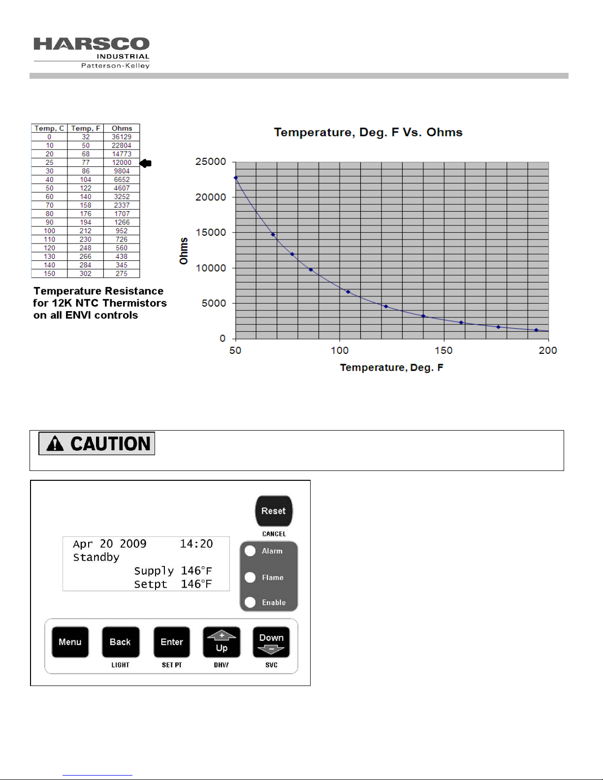
This chart represents the temperature/resistance relationship of the 12K ohm thermistor mentioned above.
ENVI® Control
The user should become thoroughly familiar with the operation of the boiler and
controls before attempting to make any adjustments.
The display panel is used to setup and monitor boiler
operation by means of six push buttons; MENU, BACK,
ENTER, UP, DOWN, and RESET as shown.
There are shortcut functions also associated with these
buttons; LIGHT, SET PT, DHW, SVC and CANCEL. The
shortcut functions are available only when the default
(home) screen is displayed.
The four line screen shows boiler operating information
on various screens. The display screen is backlit for
ease of viewing. The display panel will turn off its
backlight after a period of inactivity. Press the BACK
button to illuminate the screen.
In a cascade system it will be necessary to make control
adjustments to every boiler display panel.

5
Buttons
Function
Shortcut
Menu
Accesses the menu
None
Back / Light
Returns to the previous screen
Turns on backlight
Enter / Set Pt
Accepts the value
Accesses CH Settings
Up / DHW
Increases the value/moves cursor
Accesses DHW Settings
Down / SVC
Decreases the value/moves cursor
Accesses Service Mode
Reset / Cancel
Resets the control
Cancels Service Mode
Version 1.0 [8C51]
Patterson Kelley
Boiler Control
Run Power 65%
Supply 130
°
F
CH
Setpt
146
°
F
Supply 130
°
F
CH
Setpt
146
° F Feb 17 2013 04:27
ENVI® Control
1.0 OPERATION OF THE ENVI CONTROL
The control displays the initial boot screen (above) when first powered.
The second line of text indicates one of three possible operating configurations:
Boiler Control indicates the boiler is set up as a standalone (SA) operation (Factory default)
Master Control indicates the boiler is set up as the master in a cascade system.
Member 1 (or 2, 3, 4…) indicates the boiler is set up as a member 1 thru 24 within a cascade system.
The value shown on the fourth line of text inside the brackets [8C51] is the software version or code installed on the ENVI®
boiler controls.
There are several versions of the ENVI® control. These include 112E, BD71, 49A7, 79F2, 8C51,1043 and 9820. Not all
features are available with all versions. Parameters which are only applicable to certain release versions will be designated
accordingly. If there is no mention of versions with the parameter, then it is valid for all versions.
The control displays the default (home) screen shown above once boot up is complete.
This screen displays; the date, time, boiler status, supply temperature, setpoint temperature, error codes, present operating
mode (CH or DHW), CM=cascade master, or CS 01-24=cascade member (also referred to as subordinate or slave).
Also, firing rate, FP (freeze protection), CL (cycle limit) and firing rate (Power) may be displayed. Cycle limit & freeze
protection settings are explained later in the manual.
The control has multiple menu levels to provide set-up and operating information. Navigation through the various menus
may be performed using the buttons beneath the display. The function of the buttons may be two-fold as shown below.
The shortcut functions are available only when the default (home) screen is displayed.
6
ENVI® Control
1.1 ENVI
®
CONTROL FLOW CHART
Note: Parameter ranges in flow chart reference a typical MACH boiler. Parameter ranges will typically be different
for a condensing vs. non-condensing boiler such as the Modufire Forced Draft boiler.
7
Menu
Standby
Information
Errors
Menu
Errors
ENVI® Control
1.2 MENU SCREEN
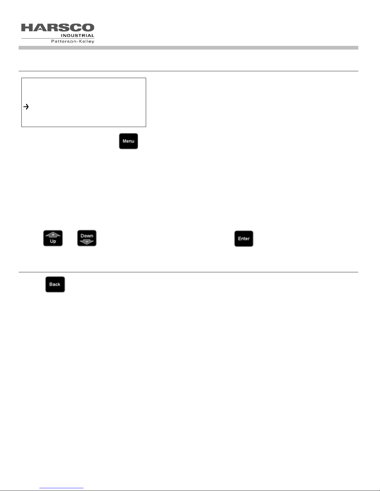
From the main screen, pressing the button provides access to the following sub-menus, shown below:
Standby
Information
Errors
Program Parameters
Configuration
Cascade Menu
Service
Use the and buttons to scroll to the desired sub menu and the button to select that sub menu.
1.3 BOILER STATUS SCREEN
Pressing while in the menu screen returns the boiler status (default) screen described in Section 1.0.
The default screen displays the current operating status. A list of possible operating statuses is shown below:
Standby – boiler waiting for a call for heat or for temperature conditions to require heat
Checking Air Switch – boiler is in its pre-ignition sequence, verifying the air switch is open prior to proceeding
Pre Purge - boiler is beginning the ignition sequence, purging the combustion chamber
Ignition - the igniter and gas valve are energized while flame is detected
Run – flame is established, igniter is de-energized, gas valve is controlled to satisfy heat load
Post Purge - boiler has completed the burn sequence and is purging the combustion chamber
Post Pumping – circulator pump is energized for a specified period to remove residual heat from the boiler
Reset – the ENVI® control has detected an error and locked out the boiler. (DO NOT reset the control without
determining and correcting the cause)
Blocking (Alarm)-Auto reset- automatic reset lockouts that will self reset when the error condition clears.
Locking (Alarm)-Manual reset- manual reset lockouts requiring an operator to press the reset button.
If the ignition sequence is started it will be finished. Even if the demand is taken away, the sequence up to the burn state is
completed.

8
Information
Supply Temp 122
°
F
Return Temp 119
° F DHW Temp 14
° F Information
Supply Temp 122
°
F
Return Temp 119
° F DHW Temp 14
° F Information
Supply Temp 122
°
F
Return Temp 119
° F DHW Temp 14
°
F
1.4 INFORMATION MENU
Pressing at the INFORMATION menu displays the following information.
Use the and buttons to scroll through the INFORMATION menu.
Below is a list of values within the Information screen. This screen is very useful for obtaining values as it displays real time
changes.
NOTE: Observe the 14°F value in the information screen above. This is the value displayed when the control recognizes an
open circuit. This is common when a particular sensor such as the DHW sensor in the example above is not used, but may
also occur in the event of an electrically open sensor or sensor circuit. The value displayed in the event of a shorted
sensor or sensor circuit is 244°F. The values will be defined further in the following table.
ENVI® Control
9
Display
Description
Units
Open/Shorted
Sensor Indication
Supply Temp
Outlet / Supply Temperature
°F
14°F (Open) / 244°F(Shorted)
Return Temp
Inlet / Return Temperature
°F
14°F (Open) / 244°F(Shorted)
DHW Temp
Domestic Hot Water Temperature at the location of the
sensor(field installed)
°F
14°F (Open) / 244°F(Shorted)
Flue gas Temp
Flue Gas Temperature
FD boiler - thermal disc switch breaks the display will
indicate 50F
°F
50°F (Open) / 280°F(Shorted)
HX Temp
Heat Exchanger Temperature available on the MACH line
C1500 thru to the C4000
°F
14°F (Open) / 244°F(Shorted)
Outside Temp
Outside Air Temperature at the location of the sensor
(field installed)
°F
-40°F / 176°F
CH set Temp
Comfort Heat Setpoint Temperature
°F
N/A
DHW set Temp
Domestic Hot Water Setpoint Temperature
°F
N/A
Header Temp
Header Temperature at the location of the sensor(field
installed)
°F
244°F / 244°F
Flame signal
Flame Signal (versions 49A7 and earlier were “YES/NO”)
μA
< 1.7 μA = Flame Not Detected
> 1.7 μA = Flame Detected 0-10
Fan speed
Fan Speed
RPM
0-9999
Analog in
Analog Input
N/A
Not Currently Used
Analog out
Analog Output
N/A
Not Currently Used
Ignitions
Number of Ignitions
#
0-99999
Burn Hi HR
Hours at High Fire (75% to 100%)
HRS
0-99999
Burn MD HR
Hours at Medium Fire (45% to 75%)
HRS
0-99999
Burn LO HR
Hours at Low Fire (20% to 45%)
HRS
0-99999
Water press
Water Pressure
N/A
Not Currently Used
Water level
Water Level Sensor Status
Aux LWCO status on FD boilers (if installed)
Off/On
0 = Low Water Cutoff
1 = Low Water Cutoff Detects Water
Low gas press
Low Gas Pressure Sensor Status
Off/On
0 = Low Gas Pressure Switch Open
1 = Low Gas Pressure Switch Closed
Air pressure
Air Pressure Switch Status
Off/On
0 = Air Pressure Switch Open
1 = Air Pressure Switch Closed
Blocked flue
Blocked Flue Switch Status
Off/On
0 = High Exhaust Back Pressure
Switch Open
1 = High Exhaust Back Pressure
Switch Closed
CH pump
Comfort Heat Pump Relay Status
Off/On
0 = CH Pump relay Off
1 = CH Pump relay On
DHW pump
Domestic Hot Water Pump Relay Status
Off/On
0 = DHW Pump relay Off
1 = DHW Pump relay On
Air damper
Air Damper Relay Status
Off/On
0 = Air Damper relay Off
1 = Air Damper relay On
Hi gas pressure
Hi Gas Pressure Switch Status
Off/On
0 = Hi Gas Pressure Switch Open
1 = Hi Gas Pressure Switch Closed
ENVI® Control

10
Apr 20 2009 14:20
Locking
IGNITION FAILURE
Err:A01
Apr 20 2009 14:20
Locking
IGNITION FAILURE
Err:A01
Display
Description
Units
Varies
Error Description
N/A
Error code
Error Code
Date
Date Error Occurred
DD-MM-YY
Time
Time Error Occurred
24:00
Supply Temp
Outlet Temperature
°F
Return Temp
Inlet Temperature
°F
DHW Temp
Domestic Hot Water Temperature
°F
Flue gas Temp
Flue Gas Temperature
°F
HX Temp
Heat Exchanger Temperature
°F
Outside Temp
Outside Air Temperature
°F
Operation Mode
Boiler Operation Mode (CH/DHW)
°F
Days run
Accumulated Days Runtime
#
State
State at time of error
ERRORS
Error 0 A03
Error 1 E01
Error 2 00
1.5 ERRORS MENU
ENVI® Control
Version [8C51] and earlier Versions [1043] and [9820]
The ENVI® control stores the most recent error. Version 1043 and after store the last 6 errors. These errors may be
locking or blocking errors.
Pressing while in the menu screen with the cursor on Errors, the ERROR menu displays a list of the last 6
errors as shown.). Pressing and scrolls through the list of errors. Pressing while the cursor is
on an error displays several lines of information about the status of the boiler during the error.
The error information recorded at the time of the error is shown in the table below.
11
Sub Menu
Description
CH settings
Comfort Heat Settings: Contains settings for specific operation of the comfort heat
operation. Contains the different modes of operations available. Holds the
outdoor air curve and night setback settings.
DHW settings
Domestic Hot Water Settings: Contains settings for specific operation of the
domestic hot water capabilities.
Boiler Settings
Boiler Operating Settings: Boiler settings contain the primary settings for the boilers
operation.
OEM Settings
Original Equipment Manufacturer Settings: These setting are non configurable and
are for information only.
ENVI® Control
1.6 PROGRAM PARAMETERS MENU
1.6.1 Initial Setup of the Control
Press the button, scroll down with the button and select PROGRAM PARAMETERS from the menu by
pushing. A screen opens that allows access to the adjustable sub menus.
Selecting and editing a sub menu
Note: There are three access levels including Service Level 1, Service Level 2, and OEM settings which can be
viewed, but cannot be changed in the field. Service Level 1 and Service Level 2 require access codes. Access codes
are provided to those individuals who have been properly trained by Harsco Industrial, Patterson-Kelley.
CAUTION: Do not change any parameter unless the function of that
parameter is thoroughly understood. Improper modification of the
parameters may cause the boiler to operate erratically or not at all.

12
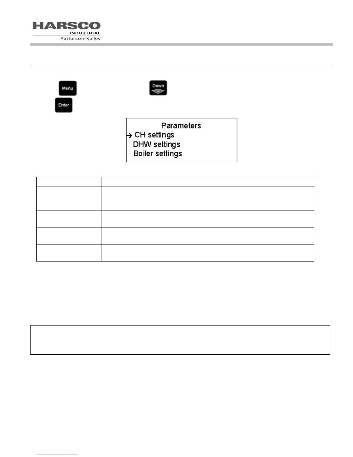
Parameters
CH settings
DHW settings
Boiler settings
Parameters
CH settings
DHW settings
Boiler settings
1.6.2 CH Settings
ENVI® Control
While in the PROGRAM PARAMETERS menu, press at the CH SETTINGS menu to access the comfort heat
parameters listed in the table below. Alternatively, pressing at the boiler status screen also accesses the CH
SETTINGS menu. You can now select any parameter by using the or then pressing . Each
parameter can be edited by using the same buttons. Once editing of each parameter is complete
save it by pressing .
13
ENVI® Text Display
Function
Range
Units
Passcode
Level
CH Setpoint
Comfort Heat Setpoint
See Appendix I
°F
User
BLR OP (Boiler Operation)
Boiler / Pump Run settings
0-3
User
Off = 0,
On = 1,
Off/Pump On = 2, and
On/Pump On = 3
0 = Boiler Off, Pump Off
1 = Boiler Auto, Pump Auto
2 = Boiler Off, Pump Continuous
3 = Boiler Auto, Pump Continuous
CH Mode
Comfort Heat Operation Mode
0-8
SVC1
CH Mode 0 (Setpoint & Stat)
See 1.6.3.1 below
0
CH Mode 1 (Outdoor &Stat)
See 1.6.3.2 below
1
CH Mode 2 (Outdoor Control)
See 1.6.3.3 below
2
CH Mode 3 (Setpoint Control)
See 1.6.3.4 below
3
CH Mode 4 (Header & Stat)
See 1.6.3.5 below
4
CH Mode 5 (Header & Outdoor & Stat)
See 1.6.3.6 below
5
CH Mode 6 (Header & Outdoor)
See 1.6.3.7 below
6
CH Mode 7 (Analog Setpoint)
See 1.6.3.8 below
7
CH Mode 8 (Analog Firing Rate)
See 1.6.3.9 below
8
Hi ODA Temp
Maximum Outdoor Air Temperature
40 – 86
°F
SVC1
Min ODA SetP
Desired setpoint @ Hi ODA Temp
See Appendix I
°F
SVC1
Lo ODA Temp
Minimum Outdoor Air Temperature
-18 – 59
°F
SVC1
Max ODA SetP
Desired setpoint @ Lo ODA Temp
See Appendix I
°F
SVC1
ODA Shutdown
Outdoor Air Shutdown Temperature
45 – 140
°F
SVC1
Night Setback
Reduces CH Set point when enabled by
this value
0 – 58
°F
SVC1
Hysteresis On
On Differential (subtract this
temperature from the setpoint for start)
0 – 22
°F
SVC1
Hysteresis Off
Off Differential (add this temperature to
setpoint for off)
0 – 22
°F
SVC1
CH Post Pump time
Post Pump Time After Burner Shuts Off
0 – 2550
Sec
SVC1
Anti-Cyc Time
Restart Time Delay to Prevent Short
Cycling
0 – 2550
Sec
SVC2
Prop Band
Proportional Band
0 – 230
°F
SVC2
Integral Rate
Integral Rate
0 – 255
Sec
SVC2
Der Time
Derivative Time
0 – 255
Sec
SVC2
Pwr lmt step (ver. 8C51, 1043, 9820)
Power limit step limits the intervals of
rate while driving towards high fire (the
lower the value, the slower the step; the
higher the value, the faster the step)
0 – 255
units
SVC2
PMP on demand (ver. 79F2, 8C51, 1043, 9820)
With the NO selection the boiler pump
only runs when there is a need to fire
the boiler.
With the YES selection the boiler pump
runs when an enable signal is present.
This is overridden by the BLR OP
setting
Yes/no
SVC2
ENVI® Control
1.6.1.1 Comfort Heat Parameters and Descriptions
14
NOTE: The boiler is enabled by the TB1/LV terminals 1 and 2 (enable/disable) becoming closed
or shorted. This circuit is energized internally. DO NOT APPLY EXTERNAL POWER TO
THESE TERMINALS.
Internal Setpoint
145
150
155
160
165
170
175
0 10 20 30 40
Time
Boiler Temperature
Boiler Set Point
Boiler Turns On
Boiler Turns Off
ENVI® Control
1.6.2 CH Modes
There are nine CH Modes (0-8). A more detailed description of each mode is included below.
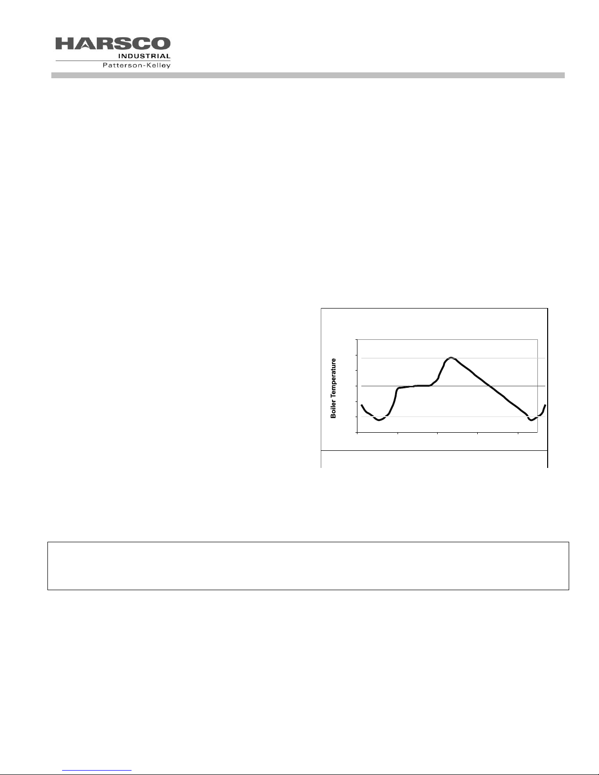
1.6.2.1 CH Mode = 0 (Setpoint & Stat)
Description
Setpoint is the desired outlet water supply temperature. Upon heat demand (or enable/disable), the ENVI® control
fires and modulates the boiler to maintain supply water temperature at the desired CH setpoint. The upper
(HYSTERESIS OFF) and lower (HYSTERESIS ON) temperature differentials within CH settings control the
temperature at which the burner turns on or off.
Example: A boiler with the following parameters (SETPOINT = 160 °F, HYSTERESIS OFF = 9 °F, HYSTERESIS ON
= 10 °F) modulates to try to maintain 160° F. If the temperature increases above 169° F (160 °F SETPOINT + 9°F
HYSTERESIS OFF), the boiler will shut off. Once it shuts off, it will not restart until the temperature drops below 150°
F (160 °F SETPOINT – 10°F HYSTERESIS ON). This is illustrated graphically below.
The MIN SETPOINT and MAX SETPOINT parameters
within the boiler settings menu limit the setpoint range. See
Appendix 3.1 and 3.2 for the default values.
CH Mode 0 is recommended for all member boilers in a cascade system with the factory installed enable jumper left in
place across LVTB -1 terminals 1 & 2.
In the event of failure of the master boiler the members will operate as standalone and control to their CH set points.
15
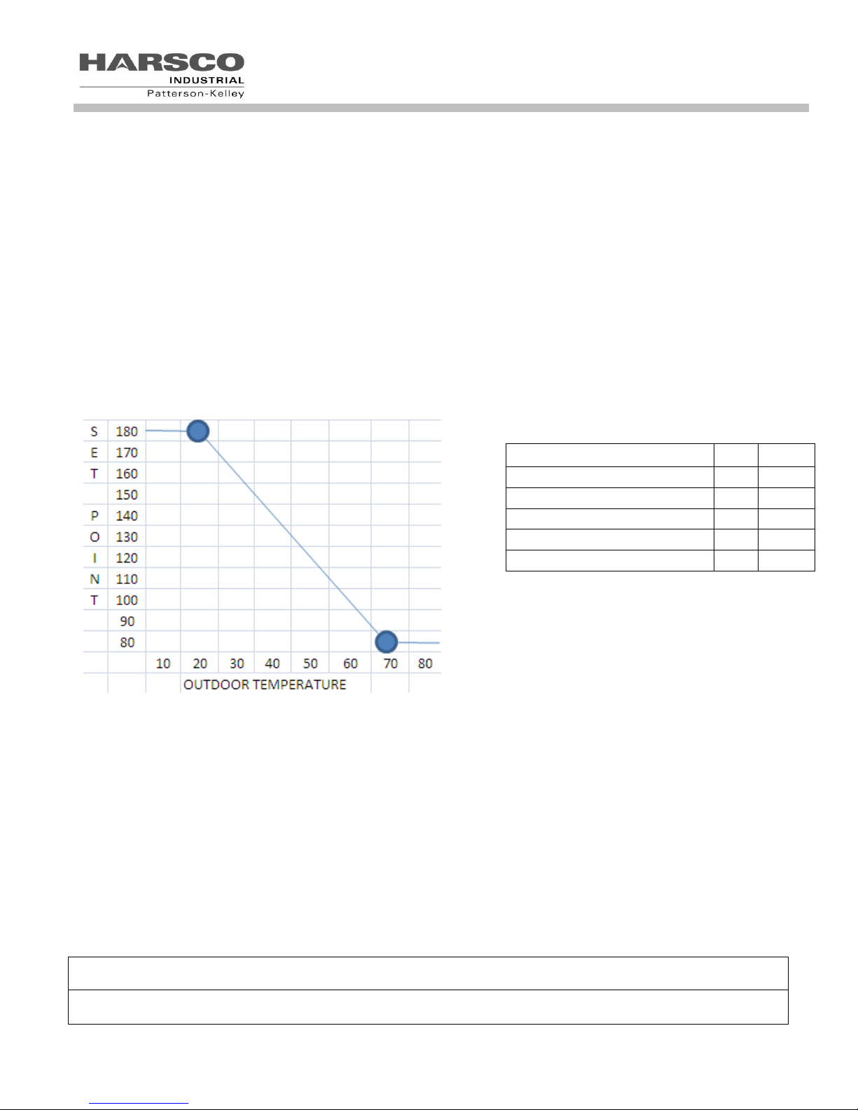
Within CH Settings
Hi ODA Temp (Outdoor TMax)
70
°F
Min ODA SetP (Setpoint TMin)
80
°F
Low ODA Temp (Outdoor TMin)
20
°F
Max ODA Setp (Setpoint TMax)
180
°F
ODA shutdown
68
°F
NOTE: The boiler is enabled by the TB1/LV terminals 1 and 2 (enable/disable) becoming closed or shorted.
This circuit is energized internally. DO NOT APPLY EXTERNAL POWER TO THESE TERMINALS.
NOTE: while using CH MODE 1 (ODA&STAT) the ODA shutdown temperature is ignored and does not
stop the boiler from running.
ENVI® Control
1.6.2.2 CH Mode 1 (ODA & Stat)
Outdoor Sensor required. A list of accessory choices for different applications is shown in section 1.0 on
page 3.
Description
In this mode, upon enabling the boiler, setpoint is varied by the outdoor air temperature (ODA). The ENVI® control
fires and modulates the boiler to maintain outlet water temperature at the setpoint which is determined by the outdoor
air temperature and its settings. The upper (HYSTERESIS OFF) and lower (HYSTERESIS ON) temperature
differentials control the temperature at which the burner turns on or off.
(FACTORY SETTINGS SHOWN ABOVE)
The Outdoor air sensor reads outdoor air temperature and sends it back to the control. The setpoint is established
based on the outdoor air temperature. If the outdoor air temperature is below the (HIGH ODA TEMP), the boiler
control begins to maintain a setpoint set by the (MIN ODA SETP). As the outdoor air temperature drops, the setpoint
temperature increases until (LO ODA TEMP) is reached by the outdoor air temperature. When the outside air
temperature has dropped to meet the (LO ODA TEMP) setting, the setpoint of the boiler will be operating at (MAX
ODA SETP).
Example: Using the values in the table shown below, the boiler setpoint is 80° F (MIN ODA SETPT) when the
outdoor air temperature is 70° F (HI ODA TEMP). As the outdoor air temperature drops, the boiler setpoint increases
until the outdoor air temperature is 20° F (LO ODA TEMP). When this occurs, the boiler reaches its maximum
setpoint of 180°F (MAX ODA SETPT). If the outdoor air temperature drops further, the boiler setpoint remains at 180°
F.

16
NOTE: The boiler is enabled when the temperature of the outdoor sensor drops below the ODA
SHUTDOWN temperature that can be changed within the CH settings.
The TB-1/LV terminals 1 and 2 (enable/disable) operate the switching on/off of the night setback function.
The night setback setpoint is set within CH settings and reduces the CH set point by its value while
enabled. (TB-1/LV terminals 1 and 2 circuit closed)
NOTE: In this mode the boiler will always run to setpoint, since there is no enable circuit closure required.
The TB-1/LV terminals 1 and 2 (enable/disable) operate the switching on/off of the night setback function.
The night setback setpoint is set within CH settings and reduces the CH set point by its value while
enabled. (TB-1/LV terminals 1 and 2 circuit closed)
NOTE: The boiler is enabled by the TB1/LV terminals 1 and 2 (enable/disable) becoming closed or
shorted. This circuit is energized internally. DO NOT APPLY EXTERNAL POWER TO THESE
TERMINALS.
ENVI® Control
1.6.2.3 CH Mode 2 (Outdoor Control)
Outdoor Sensor required. A list of accessory choices for different applications is shown in section 1.0 on page
3.
Description
In this mode, setpoint is varied by the outdoor air temperature (ODA). Upon enabling the boiler, the ENVI® control
fires and modulates the boiler to maintain outlet water temperature at the setpoint determined by the outdoor air
temperature and its settings. The upper (HYSTERESIS OFF) and lower (HYSTERESIS ON) temperature differentials
control the temperature at which the burner turns on or off.
Notes: Reference table and graph in section 1.6.2.2 for example of ODA to Boiler Temp relationship.
1.6.2.4 CH Mode 3 (Setpoint Control)
Description
In this mode, the boiler functions as described in 1.6.2.1, CH Mode 0, except that the external thermostat does not
create the call for heat. The closure of TB1/LV terminals 1 and 2 will reduce the CH setpoint by the value of the night
setback setting.
Example: Using the values, CH SP=180° F and Night Setback=10° F, when TB1/LV terminals 1 and 2 are open the
CH setpoint will be 180° F. When TB1/LV terminals 1 and 2 are closed the CH setpoint will be 170° F (180° F -10° F).
1.6.2.5 CH Mode 4 (Header & Stat) This mode is preferred for the master boiler in a cascade system.
A sensor will be needed to sense header temperature. A list of accessory choices for different applications is shown in
section 1.0 on page 3.
Description
In this mode, the boiler functions as described in 1.6.3.1, CH Mode 0, except that the boiler maintains the setpoint
temperature where the header sensor is located.
Note: Placing the master boiler in CH mode 4 on any cascade application will show the header temperature (HDR
Supply) on the display in the place of the supply temperature on the third line of text on the master boiler.

17
NOTE: The boiler is enabled when the temperature of the outdoor sensor drops below the ODA
SHUTDOWN temperature which can be changed within the CH settings.
NOTE: The TB1/LV terminals 1 and 2 (enable/disable) operate the switching on/off of the night setback
function. The night setback setpoint is set within CH settings.
NOTE: The boiler is enabled by the TB1/LV terminals 1 and 2 (enable/disable) becoming closed or
shorted.
This circuit is energized internally. DO NOT APPLY EXTERNAL POWER TO THESE
TERMINALS.
ENVI® Control
1.6.2.6 CH Mode 5 (Header & ODA & Stat)
Two sensors are required to sense header temperature and outdoor temperature. A list of accessory choices for
different applications is shown in section 1.0 on page 3.
Description
This mode is a combination of CH Mode 1 (ODA & Stat) and CH Mode 4 (Header & Stat). When the boiler is enabled
through TB1/LV terminals 1 and 2, the setpoint temperature is maintained at the location of the header sensor based
on the ODA reset schedule that is determined from the optional outdoor air sensor.
Note: While using CH MODE= 5 (HEADER&ODA&STAT) the ODA shutdown temperature is ignored and does not
stop the boiler from running.
Note: Reference table and graph in section 1.6.2.2 for example of ODA to Header Temp relationship.
Note: Placing boiler in CH mode 5 will show the header temperature (HDR Supply) on the display in the place of the
supply temperature on the third line of text on the boiler.
1.6.2.7 CH Mode 6 (Header & Outdoor)
Two sensors are required to sense header temperature and outdoor temperature. A list of accessory choices for
different applications is shown in section 1.0 on page 3.
Description
This mode is a combination of CH Mode 2 (Outdoor Control) and CH Mode 4 (Header & Stat). The temperature is
maintained at the location of the header sensor and the setpoint is based on the ODA reset schedule that is
determined from an outdoor air sensor and the night setback feature. The closure of TB1/LV terminals 1 and 2 will
reduce the CH setpoint by the value of the night setback setting.
Note: In this mode the boiler will always run to setpoint, as there is no enabling needed using this CH mode.
Note: Reference table and graph in section 1.6.2.2 for example of ODA to Header Temp relationship.
Example: Using the values, CH SP=180° F and Night Setback=10° F, when TB1/LV terminals 1 and 2 are open the
CH setpoint will be 180° F. When TB1/LV terminals 1 and 2 are closed the CH setpoint will be 170° F (180° F -10° F).

18
NOTE: When in analog control mode, enable/disable terminals are non-functional as the boiler is enabled/disabled by
applying .5 to 1.5 VDC. Dropping below .5VDC will disable the boiler.
Many times the building automation sequence of operation requires an enable/disable circuit; this can be achieved by
installing a relay in series with the control signal and opening the contacts to drop voltage to 0VDC thereby disabling
the boiler. A normally closed contact will provide fail safe operation.
ENVI® Control
1.6.2.8 CH Mode 7 (Analog Control of Setpoint)
Description
In this mode, an external 0-10 VDC signal controls the setpoint of the boiler. From the factory, the Min Setpoint is set
for 42° F for condensing boilers (130° F for non-condensing) and the Max Setpoint is set for 185° F for condensing
boilers (220° F for non-condensing). Applying a voltage of at least .5 to 1.5 VDC creates the heat request. Applying 2
VDC sets the boiler setpoint to BOILER MIN SETPOINT. Applying 10 VDC sets the boiler setpoint to BOILER MAX
SETPOINT. Applying less than .5 VDC removes the heat request. The Min and Max set points can be adjusted
within the boiler settings menu.
 Loading...