

Harsco Industrial C1500H, C2000H, C2500, C3000, C4000 Installation & Owner's Manual
MACH® C1500H – C4000
Rev. 1.03 (06/08/2012)
MACH
®
GAS FIRED BOILER
C1500H/C2000H/C2500/C3000/C4000
Natural Gas/Propane/Dual Fuel
C.S.A Design-Certified
Complies with ANSI Z21.13/CSA 4.9
Gas-Fired Low Pressure Steam and Hot Water
Model #:_______ Serial #______________________
Start-Up Date:
Harsco Industrial, Patterson-Kelley
100 Burson Street
East Stroudsburg, PA 18301
Telephone: 570.476.7261
Toll Free: 877.728.5351
Facsimile: 570.476.7247
www.harscopk.com
Boilers
ASME Code, Section IV
Certified by Harsco Industrial, Patterson-Kelley
C.S.A Design-Certified
Complies with ANSI Z21.13/CSA 4.9
Gas-Fired Low Pressure Steam and Hot Water
Boilers
_______________________
©2010 Harsco Industrial, Patterson-Kelley
Printed : 6/8/2012

MACH
®
Gas Fired Boiler
2

MACH
®
Gas Fired Boiler
.....INTRODUCTION ................................................................................................................................................ 7
1
2.....SAFETY .............................................................................................................................................................. 7
2.1 General ............................................................................................................................................. 7
2.2 Training ............................................................................................................................................. 8
2.3 Safety Features ................................................................................................................................ 8
2.4 Safety Labels .................................................................................................................................... 8
2.5 Safety Precautions ........................................................................................................................... 9
3.....INSTALLATION ................................................................................................................................................ 11
3.1 Receiving and Storage ................................................................................................................... 11
3.2 Compliance with Codes .................................................................................................................. 12
3.3 Setup .............................................................................................................................................. 12
3.4 Electrical Connections .................................................................................................................... 13
3.5 Inlet Air and Exhaust Venting ......................................................................................................... 16
3.6 Gas Piping ...................................................................................................................................... 29
3.7 Boiler Water Piping ......................................................................................................................... 31
3.8 Pre-Start Check List ....................................................................................................................... 37
3.9 Safety Checks ................................................................................................................................. 37
3.10Initial Adjustments .......................................................................................................................... 39
3.11Fuel/Air Adjustment ........................................................................................................................ 42
4.....OPERATION ..................................................................................................................................................... 44
4.1 General ........................................................................................................................................... 44
4.2 Normal Lighting and Shut-Down Procedures ................................................................................. 45
4.3 Emergency Shut-Off ....................................................................................................................... 46
4.4 Typical Boiler Operating Conditions ............................................................................................... 46
5.....MAINTENANCE ............................................................................................................................................... 47
5.1 Maintenance and Inspection Schedule .......................................................................................... 47
5.2 Cleaning the Burner ........................................................................................................................ 49
5.3 Removing the Heat Exchanger ....................................................................................................... 50
5.4 After All Repairs or Maintenance .................................................................................................... 50
5.5 Sequence of Operation ................................................................................................................... 50
5.6 Troubleshooting .............................................................................................................................. 51
5.7 Manual reset error codes-A##A (OR LOCKING ERROR CODES) ............................................... 53
5.8 Auto-reset error codes-E## (or blocking error codes) .................................................................... 54
6.....PARTS/TECHNICAL SUPPORT ..................................................................................................................... 55
6.1 Wiring Diagrams ............................................................................................................................. 56
6.2 Boiler Parts List ............................................................................................................................... 69
7.....MACH® BOILER LIMITED WARRANTY ......................................................................................................... 80
8.....APPENDIX ........................................................................................................................................................ 81
8.1 Appendix 1 – MACH® Boiler Fire Test Report ................................................................................ 81
8.2 Appendix 2 – MACH® Boiler Maintenance Log .............................................................................. 82
8.3 Appendix 3 – MACH® Boiler Altitude Derate schedule ................................................................... 83
3
c
1998 HCS, Inc. 800-748-0241
MACH
!
WARNING
Improper use may
result in fire or injury.
Read instructions/safety
manual before installing,
operating or servicing boiler.
Reorder No. 6020-V2WHPK
®
Gas Fired Boiler
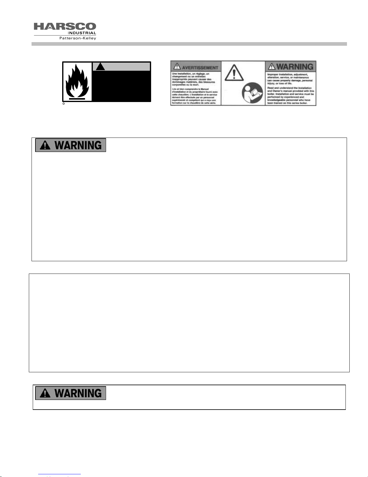
If the information in these instructions are not followed exactly, a fire or explosion may result causing property
damage, personal injury or death.
Do not store or use gasoline or other flammable vapors or liquids in the vicinity of this or any other appliance.
What to do if you smell gas:
Do not try to light any appliance.
Do not touch any electrical switch; do not use any phone in your building.
Immediately call your gas supplier from a neighbor's phone. Follow the gas supplier's instructions.
If you cannot reach your gas supplier, call the fire department.
Installation and service must be performed by a qualified installer, service agency, or the gas supplier.
AVERTISSEMENT! Assurez-vous de bien suivre les instructions données dans cette notice pour réduire au minimum
le risqué d'incendie ou d'explosion ou pour éviter tout dommage matériel, toute blessure ou la mort.
— Ne pas entreposer ni utiliser d'essence ni d'autres vapeurs ou liquids inflammables dans le voisinage de cet
appareil ou de tout autre appareil.
— QUE FAIRE SI VOUS SENTEZ UNE ODEUR DE GAZ:
• Ne pas tenter d’allumer d’appareils.
• Ne touchez à aucun interrupteur. Ne pas vous servir des téléphones dans le bâtiment où vous vous trouvez.
• Appelez immédiatement votre fournisseur de gaz depuis un voisin. Suivez les instructions du fournisseur.
• Si vous ne pouvez rejoindre le fournisseur de gaz, appelez le service des incendies.
— L’installation et l’entretien doivent être assurés par un installateur ou un service d’entretien qualifié ou par le
fournisseur de gaz.
It is essential to read, understand, and follow the recommendations of this manual
before installing, operating, or servicing this equipment.
4

who has been trained on the Harsco Industrial, Patterson-Kelley MACH® boiler. The same features which permit
this boiler to achieve high-efficiency performance make it unlike most other boilers of this general size, so it is
important to understand how this boiler operates.
MACH
Installation and service must be performed by a qualified and knowledgeable individual
®
Gas Fired Boiler
5

MACH
®
Gas Fired Boiler
6
MACH
®
Gas Fired Boiler
1 INTRODUCTION
This manual describes the installation and operation of MACH® boilers with inputs from 1.5 million through 4 million
BTUH. Natural gas, propane, and dual fuel (natural and propane) units are described. It also includes 208/3/60,
240/3/60, or 480/3/60 voltages for the 3 and 4 million BTUH input boilers. This manual describes the natural gas
design. Information for operation with other fuels is included in the various sections of this manual as applicable. If
you have any questions on the information contained within, or do not fully and completely understand the content,
please contact Harsco Industrial, Patterson-Kelley Technical Service at 570.476.7261 or toll free at 877.728.5351.
The MACH
combustion blowers, sophisticated microprocessor controls, modulating gas safety shut off / control valves and a
unique aluminum alloy heat exchanger capable of operating in a fully condensing mode to provide maximum
efficiency in a minimum amount of space. The high quality materials and thoroughly tested design of the boiler should
provide years of trouble free service if the instructions in this manual are followed carefully.
This manual covers the installation of MACH
fuel (natural gas and propane) boilers. The model number may be followed by a prefix or suffix letter in some cases to
indicate special features or different options.
While details may differ slightly, basic operation is the same for all models. Check the rating plate for correct fuel
usage and gas pressures.
The boiler is only a part of the complete heating system. This boiler may be fully operational and yet because of poor
circulation, control, or other operating characteristics not deliver heat to the desired location. Additional equipment
such as temperature sensors, pumps, flow switches, balancing valves, and check valves will be required for
satisfactory operation of any system. Harsco Industrial, Patterson-Kelley cannot be responsible for the design or
operation of such systems and a qualified engineer or contractor must be consulted.
®
C1500H/C2000H/C2500/C3000/C4000 gas fired boilers are fully modulating using variable speed
®
C1500H/C2000H/C2500/C3000/C4000 natural gas, propane, and dual
2 SAFETY
2.1 G
The MACH
Installed, operated, and serviced in accordance with instructions contained in this manual and other supplemental
Installed by qualified personnel in accordance with designs prepared by qualified facility engineers including:
Operated and serviced in accordance with a comprehensive safety program determined and established by the
Operated and serviced by experienced, qualified, and properly trained personnel in accordance with all applicable
NOTICE! Each safety device must be maintained and checked per the recommended schedule. Refer to Section
5.1 of this manual.
ENERAL
®
C1500H/C2000H/C2500/C3000/C4000 gas fired boilers must be:
manuals.
structural, mechanical, electrical, and other applicable disciplines.
customer. Do not attempt to operate or service until such a program has been established.
codes, laws, and regulations.
7
MACH
®
Gas Fired Boiler
2.2 T
RAINING
Proper training is the best protection against accidents.
It is essential to read, understand, and follow the
recommendations of this manual before installing, operating,
or servicing this equipment. Failure to do so could result in
fire or explosion and serious injury, death, and/or property
damage.
Operating and service personnel must be thoroughly familiar with the basic construction of the MACH
®
C1500H/C2000H/C2500/C3000/C4000 boilers, the use and locations of the controls, the operation of the boilers,
adjustment of their various mechanisms, and all applicable safety precautions. If any of the provisions of this manual
are not fully and completely understood, contact Harsco Industrial, Patterson-Kelley Technical Service at
570.476.7261 or toll free at 877.728.5351.
2.3 S
AFETY FEATURES
It is the responsibility of the customer to maintain the safety features, such as but not limited to: guards, safety labels,
safety controls, interlocks, lockout devices, in place and operable.
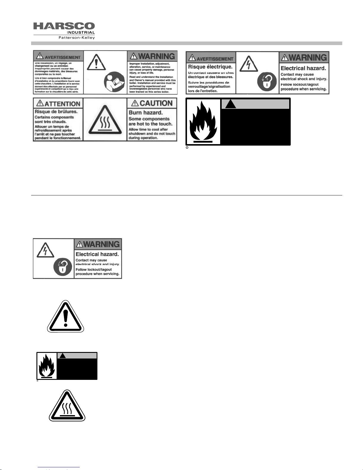
2.4 S
AFETY LABELS
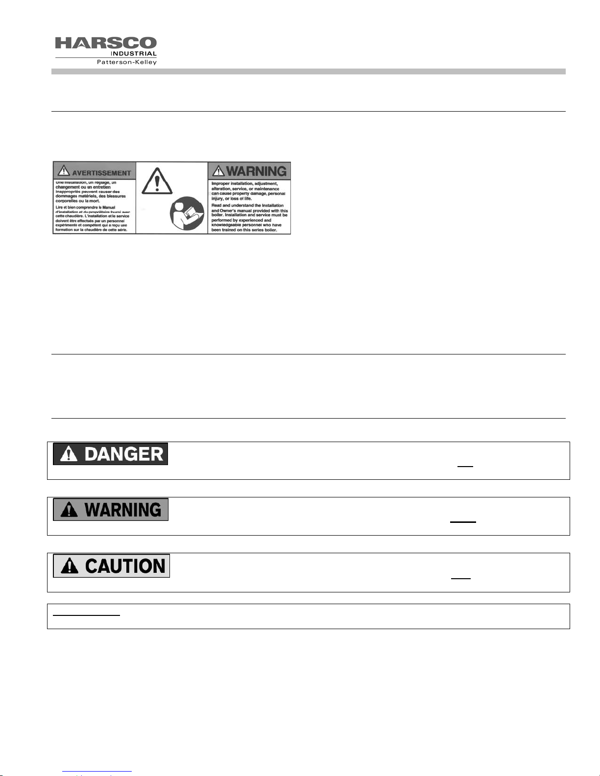
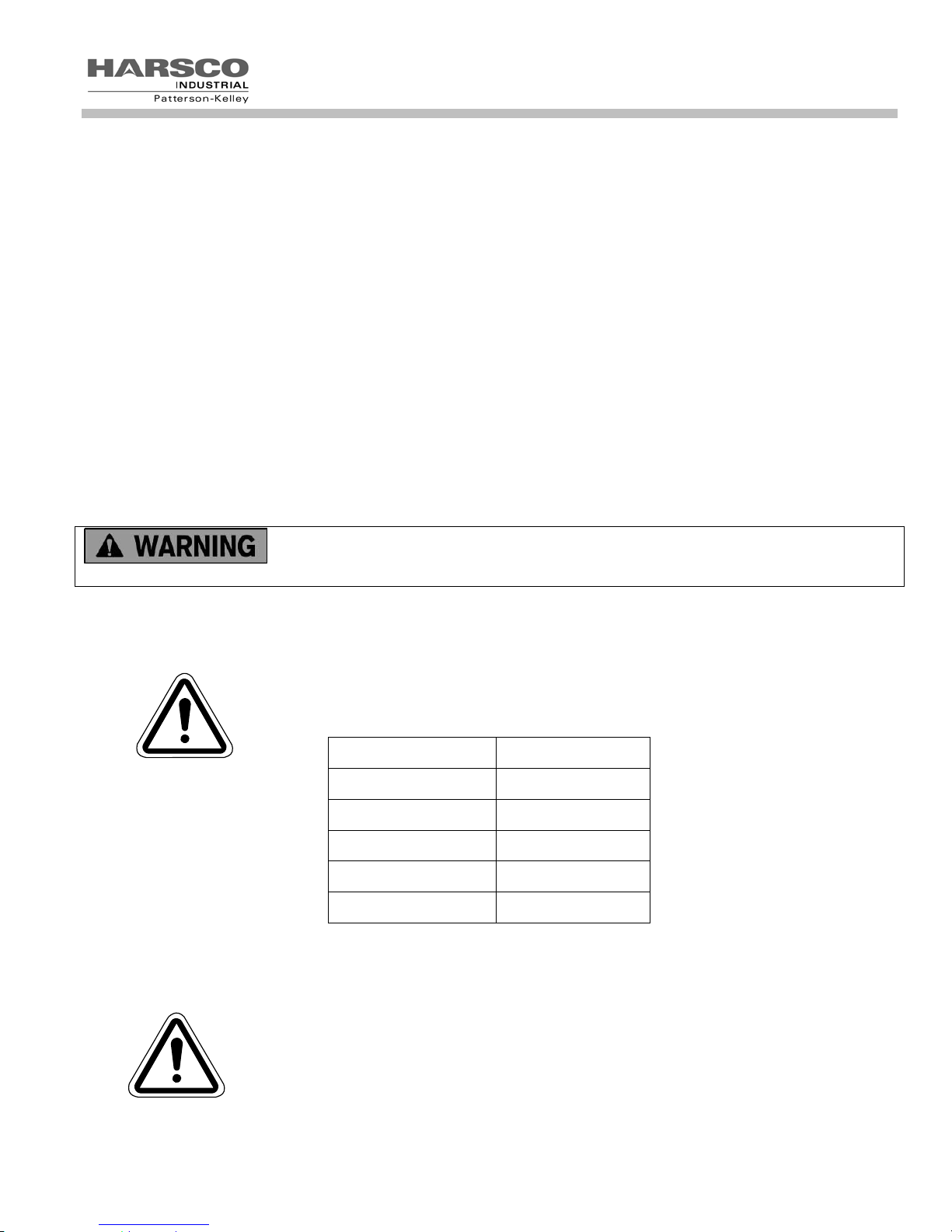
The following words are used in this manual to de-note the degree of seriousness of the individual hazards.
Indicates an imminently hazardous situation which, if not avoided, will result in death or
serious injury. This signal word is to be limited to the most extreme situations.
Indicates a potentially hazardous situation which, if not avoided, could result in death or
serious injury.
Indicates a potentially hazardous situation which, if not avoided, may result in minor or
moderate injury. It may also be used to alert against unsafe practices.
NOTICE/NOTE
- NOTICE is the preferred signal word to address practices not related to personal injury. The safety
alert symbol is not used with this signal word.
8
MACH
®
Gas Fired Boiler
c
1998 HCS, Inc. 800-748-0241
!
WARNING
Improper use may
result in fire or injury.
Read instructions/safety
manual before installing,
operating or servicing boiler.
Reorder No. 6020-V2WHPK
The safety labels shown above are affixed to your boiler. Although the labels are of high quality, they may become
dislodged or unreadable over time. Contact Harsco Industrial, Patterson-Kelley at 570.476.7261 or toll-free at
877.728.5351 for replacement labels.
2.5 S
AFETY PRECAUTIONS
Provide a suitable location for the boiler, away from normal personnel traffic, with adequate working space, adequate
clearances, proper ventilation and lighting, with a structure sufficiently strong and rigid to support the weight of the
boiler, all piping, and accessories.
2.5.1 Electrical Hazards
Shock hazard! Properly lockout/tag out the electrical service and all other
energy sources before working on or near the boiler.
Shock hazard! Do not spray water directly on this boiler or on any electrical
components.
Electrical hazard! Do not alter wiring connections.
2.5.2 Burn, Fire, and Explosion Hazards
Burn, fire, and explosion hazards! Installation must be in strict conformance to all
applicable codes and standards including NFPA 54, ANSI Z223.1 and CAN/CSA
B.149. Install all required vent lines for gas devices. Refer to Section 3.6.
Hazard from incorrect fuels! Possible fire, explosion, overheating, and damage. Do
General Warning
not use any fuels except the design fuels for the unit.
Over fire hazards! High pressure in gas supply could result in over firing of this or
other devices supplied from the same source.
!
c
1998 HCS, Inc. 800-748-0241
WARNING
Improper use may
result in fire or injury.
Read instructions/safety
manual before installing,
operating or servicing boiler.
Reorder No. 6020-V2WHPK
Fire and explosion hazards! Close the main gas shutoff before servicing boiler.
Fire and explosion hazards! Do not store or use gasoline or other flammable vapors
or liquids in the vicinity of this or any other gas fired appliance.
Burn hazard! Possible hot surfaces. Do not touch gas vent during firing operation.
Use only factory recommended vent components.
Burn hazard! Pipes, vents, and boiler components could be hot. Do not touch piping
or stack surfaces during operation or immediately after shutdown of the boiler.
Burn hazard! Hot fluids. Use caution when servicing or draining boiler.
Hot Surface
9
MACH
®
Gas Fired Boiler
Fire and explosion hazards! Use caution when servicing burner. Propane (LPG) is heavier than air and may
linger in the combustion chamber, vent lines, or elsewhere.
Gas leak hazard! Make sure the burner is installed correctly and blower/transition is securely fastened following
any maintenance performed on them. These connections may leak gas if assembled incorrectly.
Gas leak hazard! All threaded gas connections must be made using a pipe compound that is resistant to liquefied
petroleum gas. Do not use Teflon tape on threaded gas piping.
Gas leak hazard! Check entire gas train for leaks after installation. If there is a smell of gas, shut down the boiler
and obtain immediate assistance from trained service personnel and/or your local fire department.
Over fire hazard! Possible fire and explosion from excess gas pressure. Make sure that gas inlet pressure does
not exceed 14 inches W.C.
Over fire hazard! Possible fire and explosion. Possible malfunction of regulators and/or gas safety shut off /
control valves. Maintain all gas train components in good condition. Do not alter wiring connections. Annual
inspection by factory-trained personnel for proper set-up and operation is recommended.
Over fire and under fire hazards! Possible fire, explosion, overheating, and component failure. Do not attempt to
adjust firing rate of the boiler. The firing rate must be adjusted only by factory trained personnel.
Gas may lose its odor. Proper gas sensing equipment and procedures should be used for
leak checks.
2.5.3 Crush Hazards
Lifting hazards! Use properly rated lifting equipment to lift and position the boiler. The
load is unbalanced. Test balance before lifting 3 ft. above the floor. Do not allow
personnel beneath the lifted load. Refer to approximate weights in the table.
General Warning
Bump hazard from overhead ductwork and piping. Install components with adequate
vertical clearance.
2.5.4 Chemical Hazards
Boiler Size Weight in Pounds
C1500H 1,200 lbs
C2000H 1,400 lbs
C2500 1,550 lbs
C3000 1,600 lbs
C4000 1,900 lbs
• Chemical hazards from cleaning products. Use caution when cleaning the system. The
use of professional assistance is recommended. Use safe procedures for the disposal of
all cleaning solutions.
• Combustion Condensate – an acidic pH of approximately 3.0 to 5.0 can be expected.
General Warning
Use PVC, CPVC, or other corrosion resistant piping for drainage. Collection and disposal
must be in accordance with all applicable regulations. A condensate neutralization kit is
available. Please contact your local Harsco Industrial, Patterson-Kelley representative.
10
MACH
2.5.5 Pressure Hazards
Pressure hazard! Hot fluids. Install isolation valves on boiler water inlet and outlet.
Make sure isolation valves are closed before servicing boiler.
Pressure hazard! Hot fluids. Annually test safety relief valve for proper operation. Do
not operate boiler with faulty relief valve.
General Warning
2.5.6 Slip, Fall Hazards
Tripping hazard! Do not install piping on floor surfaces. Maintain clear path around
boiler.
Slip and fall hazard! Use drip pan to catch water while draining the boiler. Maintain dry
floor surfaces.
®
Gas Fired Boiler
General Warning
Slip and fall hazard! Do not locate intake or exhaust terminations directly above a
walkway; dripping of condensation can cause icing of the walking surface. (see section
3.5)
Fall hazard! Do not stand on boiler.
3 INSTALLATION
Installation and service must be performed by a qualified installer, service agency, or
gas supplier.
3.1 R
3.1.1 Initial Inspection
Upon receiving the boiler, inspect it for signs of shipping damage. Since some damage may be hidden, unpack
the boiler, open the front, and side doors and inspect the boiler. Verify that the total number of pieces shown on the
packing slip agrees with those actually received.
NOTICE! Note any damage, suspected potential damage, or shortage of materials on the freight bill and immediately
notify the carrier. File all claims for shortage or damage with the carrier. Claims for hidden damages must be filed
with your carrier within 7 days. The boiler carton is equipped with a “Tip (N) Tell”. If "Tip (N) Tell” arrow point is blue,
that indicates that the package has been on its side or tipped over in transit.
ECEIVING AND STORAGE
3.1.2 Storage Prior to Installation
If the boiler is not installed immediately, it must be stored in a location adequately protected from the weather,
preferably indoors. If this is not possible, then it should remain in the shipping container and be covered by a
tarpaulin or other waterproof covering.
NOTICE! Controls and other equipment that are damaged or fail due to weather exposure are not covered by
warranty.
11
MACH
®
Gas Fired Boiler
3.2 C
OMPLIANCE WITH CODES
MACH® boilers with standard components and with many options complies with American National Standard/CSA
Standard ANSI Z21.13/CSA 4.9, latest edition, Gas Fired Low Pressure Steam and Hot Water Boilers.
The heat exchanger is constructed and stamped in accordance with ASME Boiler and Pressure Vessel Code, Section
IV for 125 psig maximum operating pressure.
Installation of the boiler must conform to all the requirements of all national, state and local codes established by the
authorities having jurisdiction or, in the absence of such requirements, to the National Fuel Gas Code, ANSI
Z223.1/NFPA 54 latest edition in the U.S. In Canada, the equipment shall be installed in accordance with the current
Installation Code for Gas Burning Appliances and Equipment, CAN/CSA-B.149, latest edition, and applicable
Provincial Regulations for the class, which should be carefully followed in all cases. Authorities having jurisdiction
should be consulted before installations are made.
Where required by local codes, the installation must conform to American Society of Mechanical Engineers Safety
Code for Controls and Safety Devices for Automatically Fired Boilers (ASME CSD-1).
In the Commonwealth of Massachusetts (a) this unit must be installed by a licensed pipe fitter / plumber, (b) field
installed gas cocks must be “T” handle type, (c) piping of condensate shall conform to the State Plumbing Code, and
(d) refer to the Massachusetts Supplement for further details.
3.3 S
ETUP
3.3.1 Foundation and Placement
Provide a firm, level foundation, preferably of concrete.
The wheels provided with this boiler are for positioning purposes only. When positioning
this boiler, maintain positive control of it at all times. Do not attempt to move the boiler on surfaces that are not
level. Failure to heed this warning could result in personal injury or death.
Lifting the front of the boiler slightly will allow the boiler to be rolled off the shipping skid onto the concrete foundation.
Once in position, the wheel bolts may be removed allowing the wheels to recess up into the boiler. The base will sit
flat on the provided foundation. All of our boilers are supplied with leveling feet to adjust the boiler to a level position
on the floor. This is very important to maintain proper condensate drainage and correct op eration of the boiler. If the
boiler is to be pulled out for maintenance, the wheels may be left attached.
3.3.2 Placement
The boiler must be level to function properly. There are six 9/16” holes in the base that may be used for 3/8” seismic
anchors.
NOTICE! The boiler may be installed on a combustible floor; however, the boiler must never be installed on carpeting.
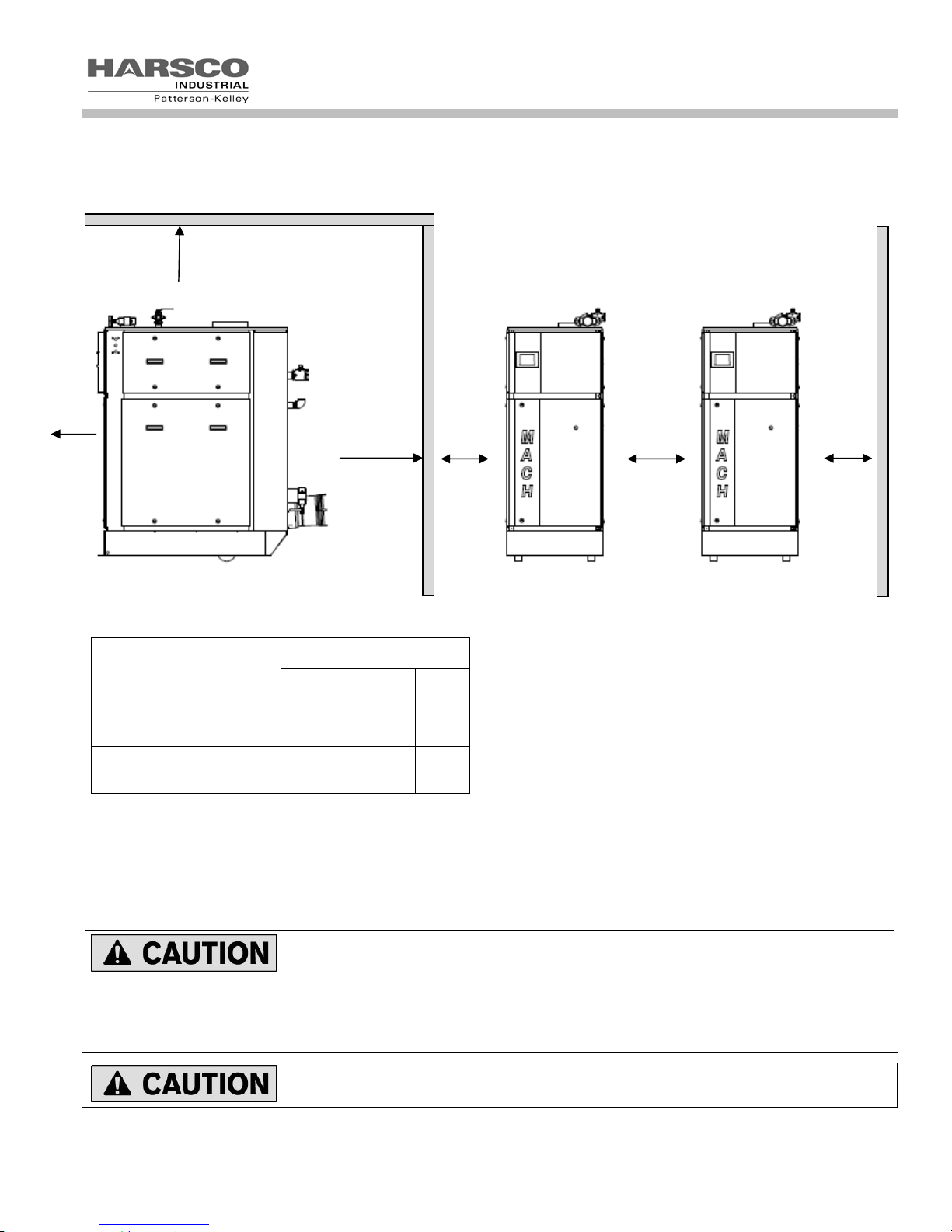
3.3.3 Clearances
If the boiler is to be installed near combustible surfaces, the minimum clearances shown in the pictures and table
below must be maintained. Failure to provide for the service access clearances, even with non-combustible surfaces,
may cause future problems servicing the boiler. Maintain a clearance from the vent to combustible surfaces of 18” or
as specified in the vent manufacturer’s listed installation instructions. The boiler must be installed in a space large in
comparison to the boiler as described in the National Fuel Gas Code, ANSI Z223.1, latest edition.
12
A
MACH
®
Gas Fired Boiler
C
B
D
D
D
Minimum Clearances from Adjacent Walls, Ceiling, and Obstructions
Type of Surface Dimensions (inches)
A B C† D
Combustible Surfaces
Minimum Clearances
Recommended Clearances
for Service Access
† "C" Space required for pipes, ducts, etc. in this area above the boiler.
* “B” Clearance depends upon exhaust vent configuration.
** Do not
doors can be opened.
clearances.
put pipes, ducts, vents, etc in this space. Electrical conduit must be installed vertically so that the side
18 6 12 6
30 12* 12 18**
Bumping hazard from overhead ducts! Install all components with adequate vertical
3.4 E
LECTRICAL CONNECTIONS
Be sure to check the nameplate on the boiler before connecting electrical supply.
13

MACH
®
Gas Fired Boiler
NOTICE! A dedicated earth ground (green wire) is required to avoid nuisance shutdowns. Do not ground through
the conduit.
MACH© C1500H/C2000H/C2500 boilers require 120 volts, single phase, 60 hertz electrical service.
The MACH
NOTE: MACH
©
C3000/C4000 boilers require either 208VAC/ 240VAC OR 480VAC three phase, 60 hertz
®
C3000/C4000 boilers must be ordered as either 208/240VAC or 480VAC THIS IS NOT FIELD
CONFIGURABLE.
If 208 VAC is used the step down transformer must be reconfigured for 208VAC by changing the connection on the
transformer located inside of the power input junction box (see MACH
®
boiler transformer wiring diagrams for proper
configuration).
The total operating amperage is indicated on the rating nameplate. Before starting the boiler, check to ensure that the
proper electrical service is connected to the boiler.
An external electrical disconnect (not supplied with the boiler) is required. The boiler electrical service must be
installed and grounded in accordance with local codes or in the absence of such requirements, in the U.S. with
National Electrical Codes, ANSI/NFPA No. 70 latest edition or, in Canada, to the Canadian Electrical Code, Part I,
CSA C22.1, latest edition. Installed conduit must not block openings and must allow the side doors to be opened.
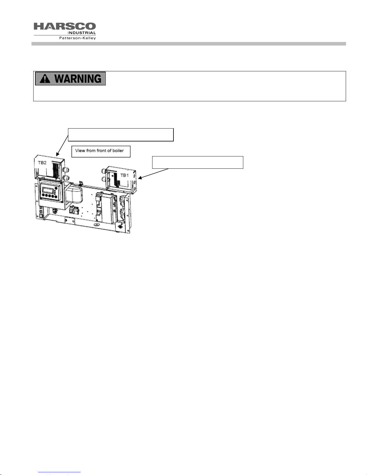
The electrical junction boxes are located at the upper front sides of the boiler.
The MACH
®
C3000/C4000 boilers have an added electrical junction box at the
lower front left side.
©
3.4.1 Power Input Junction Box MACH
C3000/C4000 Boilers
Power Input Junction Box
For the C3000 and C4000
The main power connections are connected to the over current safety device
rated for a 20 Amp 3 phase circuit (for either 208-240 or 480VAC) and ground
terminal located in the main power connection box. This box is located at the
lower front left side of the boiler. The power connection has four points of
contact: Terminals 1, 3, 5 and G. Connect the three wires supplying the three
phase power to terminals 1, 3 and 5. Connect the main boiler ground wire to
G.
The MACH
©
C3000/C4000 boilers internal control transformer is pre-wired
from the factory for operation with 240 VAC or 480VAC. If 208 VAC three
phase power is used on the 240VAC model, the internal control transformer
must be wired for operation at this lower voltage. The wire in terminal X3 on
the load side of the internal control transformer must be moved to terminal X4.
This supplies the 120 VAC power to the controls from the 208 VAC main
voltage. Refer to Sections 6.1.4 and 6.1.5 for proper wiring and configuration
of the internal control transformer.
3.4.2 Power Input Junction Box or Terminal Block 2 (TB2) MACH
©
C1500H/C2000H/C2500 Boilers
The main power connection is made within the TB2/HV terminal block to terminals:
1 - 120VAC LINE L1+
2 - 120VAC NEUTRAL N1 8 - GROUND G
14
MACH
3.4.3 High Voltage (TB2) Terminal Block
®
Gas Fired Boiler
For MACH
®
C3000/C4000 boilers, the high voltage (TB2) terminal block is for 120VAC
output pilot duty loads only. Do not connect any 120VAC supply voltage to the high voltage (TB2) terminal block.
Connecting a 120VAC supply voltage to TB2 can result in serious injury or death.
120 VAC Neutral- These terminals provide the neutral wires for the boiler 120 VAC outputs.
TB2 high voltage terminal block
TB1 low voltage terminal block
120VAC Switched Output- This contact closes when the boiler is switched on. This provides 120 VAC, 0.5 Amp
service to TB2-10. The neutral for this circuit is provided on TB2-3. When the boiler is switched off, this terminal is
switched off as well.
3 Way Valve- This output is normally energized, keeping the three way valve open, providing heat to the building.
The Domestic Hot Water (DHW) call for heat de-energizes this circuit, causing the 3 way valve to self close, thereby
providing heat to the DHW loop. This output provides 120 VAC, 0.5 Amp service to TB2-11. The neutral for this
circuit is provided on TB2-4. Note: the 3 way valve is a field sourced part.
DHW Pump Relay w/ Delay Off - This output is enabled when there is a call for DHW. When the call for heat is
removed, the output remains enabled for the post pump time parameter within the DHW settings. This output
provides 120 VAC, 0.5 Amp service to TB2-12. The neutral for this circuit is provided on TB2-5.
Circ Pump Relay w/ Delay Off - This output is enabled when there is a call for heat. When the call for heat is
removed, the output remains enabled for the post pump time parameter within the CH settings. This output provides
120 VAC, 0.5 Amp service to TB2-13. The neutral for this circuit is provided on TB2-6.
Damper Relay - This output is enabled when the call for heat is enabled. This output provides 120 VAC service to
TB2-14. The neutral for this circuit is provided on TB2-7. This circuit is for pilot duty only.
Master Alarm Relay – This is a dry set of contacts that are normally open and will close in the event of an alarm
output from the boiler control, connecting TB2-15 and TB2-16.
Flame Detected Relay – This is a dry set of contacts that are normally open and will close whenever the boiler
control is reading a flame, connecting TB2-17 and TB2-18.
15

MACH
®
Gas Fired Boiler
3.4.4 Low Voltage (TB1) Terminal Block
Enable/Disable– TB1-1 and TB1-2 are used for enabling the boiler. Closing this circuit allows the boiler to run.
Opening this circuit prevents the boiler from running. This circuit is energized by the boiler. It has a 24 VAC potential.
Devices connected to these terminals must be rated for 24 VAC
Note: This circuit will become unusable in certain CH modes and Cascade Master Modes dealing with 0-
10vdc.
External Interlock – TB1-3 and TB1-4 are used for attachment of an additional field safety device to the boiler control
circuit. Closing this circuit allows the boiler to run. Opening this circuit prevents the boiler from running. This circuit is
energized by the boiler with a 5 V potential. Devices connected to these terminals must be rated for 5 V.
Outdoor Temp Sensor – TB1-5 and TB1-6 are connected to the outdoor temperature sensor. The temperature
control must be programmed to run an outdoor air schedule. The outdoor air sensor and programming help are
available from the local Harsco Industrial, Patterson-Kelley Representative. This circuit is energized by the boiler with
a 5 V potential. The temperature sensor must be a NTC having 12 k @ 77°F.
DHW Stat/Sensor – TB1-7 and TB1-8 are connected to the DHW temperature sensor or thermostat. This circuit is
energized by the boiler with a 5V potential. The temperature sensor must be a NTC having 12 k @ 77°F.
Header Temp Sensor – TB1-9 and TB1-10 are connected to the header temperature sensor. This circuit is
energized by the boiler with a 5 V potential. The temperature sensor must be a NTC having 12 k @ 77°F.
DHW Flow Switch – TB1-11 is energized by the boiler with a 5 V potential. This circuit connects through a flow
switch on the domestic side of a domestic hot water system. The flow switch should close upon flow to provide a
closed circuit back to TB1-12.
Analog Input– Remote signal for controlling the boiler. The boiler can be operated in a remote setpoint or a remote
firing rate control mode. Input 0-10 VDC+ signal on TB1-13 only. The 0 VDC- Analog Input is provided on TB1-14.
The temperature control must be programmed to run with the analog input. (See the ENVI
®
Control Advanced Users
Guide for more information)
MODBUS® – TB1-17 and TB1-18 are used for connecting a MODBUS® building management system. (See the
®
ENVI
Control Advanced Users Guide for more information)
Cascade – TB1-19 and TB1-20 are used to connect between boilers that are part of a Master/Member Network. Up to
24 boilers may be connected together. (See the ENVI
®
Control Advanced Users Guide for more information)
3.5 I
NLET AIR AND EXHAUST VENTING
3.5.1 Applicable Codes & Standards
CODES
United States:
NFPA 54/ANSI Z223.1 National Fuel Gas Code
NFPA/ANSI 211 Chimneys, Fireplaces, Vents and Solid Fuel Burning Appliances
Canada
CAN/CSA B149.1 Installation Codes for Gas Burning Equipment
STANDARDS
UL 1738 Venting Systems for Gas-Burning Appliances, Categories II, III, and IV
ULC S636-95 Standard for Type BH Venting Systems
Sheet Metal and Thermoplastic Duct Construction Manual
Air Conditioning Contractors National Association (SMACNA)
16

MACH
®
Gas Fired Boiler
These codes and standards contain information for the venting of gas fired appliances, including, but not limited to
vent sizing, location, clearance to combustibles, and safe installation practices. The installation must comply with
both the above Federal Codes and with state, provincial and local codes.
Design and installation of venting systems should be done only by qualified and
knowledgeable venting systems personnel and in accordance with vent system manufacturer’s installation
instructions. Installing a boiler or vent system using improper installation methods or materials can result in serious
injury or death due to fire or asphyxiation.
Before connecting a boiler to a venting system, it must be determined whether the boiler
is to be installed in a conventional or Direct Vent configuration. In the US, provisions for combustion and ventilation
air must be in accordance with NFPA 54/ANSI Z223.1, National Fuel Gas Code, latest edition, or applicable
provisions of the local building codes. In Canada, combustion and ventilation air openings shall comply with
CAN/CSA B-149.1 Natural Gas and Propane Installation Code.
For correct installation of vent system, read all of these instructions and refer to vent
manufacturer’s instructions.
Failure to use a proper vent system (types and materials), as described in this manual will void the boiler warranty
and may result in rapid deterioration of the venting system, creating a health or life safety hazard.
Faulty vent installation can allow toxic fumes to be released into living areas. This may cause property damage,
serious bodily injury or death.
Table of Required Stainless Steel Vent Adapters and Category II Motorized Dampers
Boiler
Size
Nominal
vent Size
Stainless
Vent Adapter
Vent
adapter
size
Boiler air
inlet for
combustion
air
Combustion
air Normally-
Closed
Motorized
A
Damper
C300 4” 2600000593
C450 5” 2600000594
C750 6” 2620000181
C900 8” 2620000366
C1050 8” 2620000366
C1500 10” 2630000226
C2000 10” 2630000225
C2500 10” 2640000133
C3000 10” 2640000133
C4000 10” 2640000133
4” 6”
5” 6”
8”x6” 6”
8” 6”
8” 6”
10”x8” 10”
10”x8” 10”
10” 12”
10” 12”
10” 12”
1004906943 6”
1004906943 6”
1004906943 6” size
1004906944 8” as
1004906945 10” needed
1004906945 10” size
1004906945 10” as
1004906946 12” need
1004906946 12”
1004906989 14”
NOTICE! This table is for information only. Combustion air dampers and vent adapters are listed for use of design
and may or may not be specific to your application.
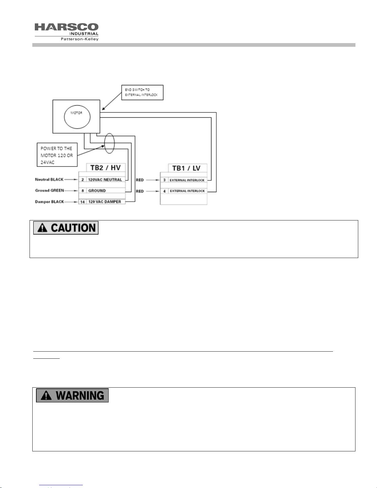
The optional, but required for Category II venting, normally-closed motorized combustion air damper operates on 120
VAC and features an end limit switch wired into the boiler’s external interlock circuit. Upon a call for heat, the boiler’s
17
MACH
®
Gas Fired Boiler
combustion air damper relay will energize and drive the damper open. Once the damper reaches the fully-open
position, the end limit switch makes contact and closes the external interlock circuit allowing the boiler to fire. The
diagram below shows the wiring necessary to install the normally-closed motorized damper.
Use caution if installing a barometric damper in the exhaust vent. The vent pressure must
be negative from the barometric to the vent termination (Category II) at all times to prevent leakage of harmful flue
gases into the room. Leakage of flue gases can cause serious injury or death. Note: this applies to Category II
venting only.
3.5.1.1 Gas Vent Categories
Several codes and standards have categorized appliances in accordance with the flue gas temperature and pressure
produced by the appliance. The applicable categories are defined as follows:
Category II An appliance that operates with a non-positive vent static pressure and with a vent temperature
that may cause excessive condensate production in the vent.
Category IV An appliance that operates with a positive vent static pressure and with a vent temperature that
may cause excessive condensate production in the vent.
Direct Vent An appliance that is constructed and installed so that all air for combustion is derived directly
from outdoors and all flue gases are discharged to the outdoors.
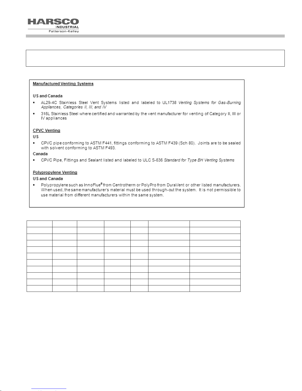
3.5.1.2 Venting Materials for Flue/Exhaust Systems
The MACH
appliance, which vents with a temperature that is likely to cause condensation in the vent. Therefore, any venting
system used with the MACH
®
C1500H/C2000H/C2500/C3000/C4000 boilers are dual certified as a Category II and Category IV
®
boiler must comply with the requirements for either Category II or Category IV venting
systems as specified in the latest edition of NFPA 54/ANSI Z223.1 in the US or the latest edition of CAN/CSA B-149.1
in Canada.
The venting materials listed below are intended for the venting of gas burning
appliances only. Do not use these venting materials for venting liquid or solid fuel (such as oil, kerosene, wood or
coal) appliances
Maintain clearances to combustibles as listed in the vent manufacturer’s installation instructions or as set forth in
the codes and standards listed in this section.
Do not use these vent pipes for incinerators of any sort.
18
MACH
®
Gas Fired Boiler
This boiler is not certified for use with PVC venting. Use of PVC vent may result in vent failure and possible
serious injury or death.
Table of Acceptable Materials for Venting Systems
Table of Applicable Vent Materials
Model
C1500H
C2000H
C2500
C3000
C4000
C1500H
C2000H
C2500
C3000
C4000
Country
US
US
US
US
US
Canada
Canada
Canada
Canada
Canada
AL29-4C 316L SS PVC
X X No
X X No
X X No
X X No
X X No
X X No
X X No
X X No
X X No
X X No
CPVC POLYPROPYLENE
X NOTE 3
X NOTE 3
X NOTE 3
X NOTE 3
X NOTE 3
NOTE 2 NOTE 2
NOTE 2 NOTE 2
NOTE 2 NOTE 2
NOTE 2 NOTE 2
NOTE 2 NOTE 2
Note 2: When this material is used for venting, it must be listed to ULC-S636.
Note 3: When this material is used for venting, it must be listed to UL-1738.
19
MACH
®
Gas Fired Boiler
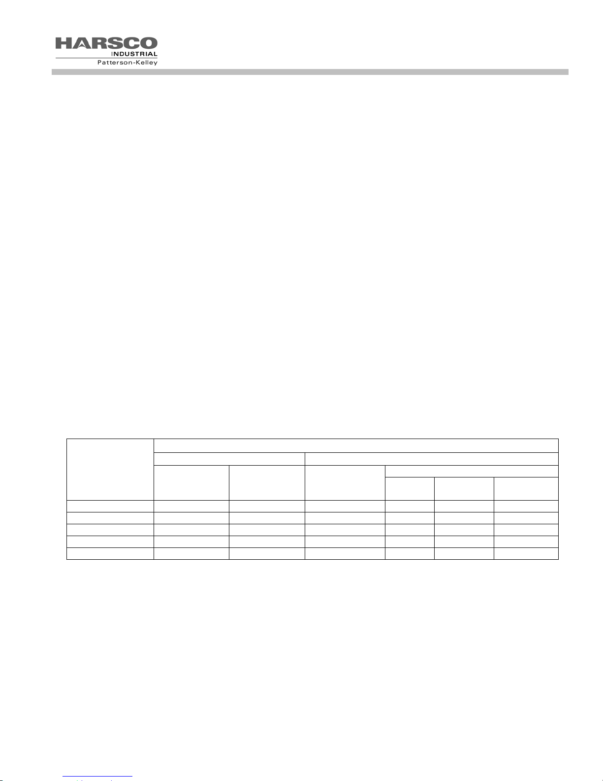
3.5.2 Combustion Air Materials and Sizes
Air Requirements – SCFM
MACH® Boiler MODEL
Required SCFM
The air intake duct can be fabricated from PVC, CPVC, single wall
galvanized steel, or other suitable materials. The duct must be rigid
C1500H 350
enough to maintain the full required cross sectional area under all
operating conditions. Proper sealing of the intake ductwork is necessary
C2000H 467
to prevent infiltration of air from conditioned space. Joints in PVC or
CPVC must be cemented. For galvanized duct, wrap each joint and
seam with adhesive aluminum tape or other sealant. The installation of a
C2500 584
bird screen on the intake termination is recommended. Ensure that the
screen does not become blocked with snow, ice, insects etc. Combustion
C3000 629
C4000 839
air duct should be designed with .22”W.C. friction loss per 100’ of duct.
Combustion air must be free from dust, lint, etc. The presence of such materials in the air supplied to the burner
could cause nuisance "Low Air" shutdowns or premature burner failure. The boiler should not be operated during
construction while the possibility of drywall dust, demolition dust, etc. exists.
The combustion air supply must be completely free of chemical fumes which may be corrosive when burned in the
boiler. Common chemicals which must be avoided are fluorocarbons and other halogenated compounds, most
commonly present as refrigerants or solvents, such as Freon, trichloroethylene, perchloroethylene, chlorine, etc.
These chemicals, when burned, form acids which quickly attack the boiler and the boiler stack. The result is improper
combustion and premature boiler failure.
Under no circumstances shall the boiler room ever be under a negative pressure.
Particular care should be taken when exhaust fans, compressors, air-handling units or other equipment may rob air
from the boiler. Note that this equipment might be in rooms other than the boiler room. This applies to both sealed
combustion and atmospheric room combustion air applications.
3.5.2.1 Air Inlet Requirements – United States (NFPA 54/ANSI Z223.1 & NFPA/ANSI 211)
When air is supplied from inside the building, the total required volume shall be the sum of the required volume for all
the appliances located in the mechanical room. Adjacent rooms furnished with fixed openings communicating directly
with the mechanical room are considered part of the required volume. The minimum volume is 50 ft
3
(4.8 m
/kW) of installed appliance input capacity.
Openings used to connect indoor spaces to obtain the required minimum volume shall be sized as follows:
When rooms are on the same floor, each opening shall have an area equal to 1 square inch for each 1000 Btu/hr
(2200 mm
2
/ kW) of installed appliance input capacity, but not less than 100 square inches. One opening should
commence less than 12 inches above the floor and the other less than 12 inches below the ceiling. The minimum
dimension of air openings shall be 3 inches.
3
per 1000 Btu/hr
When rooms are on different floors, each opening shall have an area equal to 2 square inches for each 1000
Btu/hr (4400 mm
2
/ kW) of installed appliance input capacity.
20
MACH
®
Gas Fired Boiler
When combustion air is supplied from outside the building, the boiler room shall be provided with one or two openings
to ensure adequate combustion air and proper ventilation.
When using one permanent opening, the opening shall commence within 12 inches of the ceiling and shall
communicate directly with the outdoors or through a vertical or horizontal duct that communicates to the outdoors.
2
Minimum free area of the opening is 1 square inch for each 3000 Btu/hr (700 mm
/ kW) of installed appliance
input capacity, and
1. Not less than the sum of the areas of all vent connectors in the room.
When using two permanent openings, one opening shall commence within 12 inches above the floor and the other
within 12 inches below the ceiling, preferably on opposite walls. The openings shall communicate directly, or by way
of ducts, with free outdoor air. The minimum net free area of the openings shall be calculated in accordance with the
following:
When air is taken directly from outside the building, each opening (minimum of two, as outlined above), 1 square
inch for each 4,000 Btu per hour (550 mm
When air is taken from the outdoors through a vertical duct into the mechanical room, 1 square inch per 4,000 Btu
per hour (550 mm
When air is taken from the outdoors through a horizontal duct into the mechanical room, 1 square inch per 2,000
Btu per hour (1100 mm
2
/kW) of total boiler input is required.
2
/kW) of total boiler input is required.
2
/kW) of total boiler input is required.
NOTE:
1. The required size of openings for combustion and ventilation air shall be based on the net free area of the
opening.
2. Screens shall be not smaller than ¼”
3. Motorized louvers shall be interlocked with the appliance so that they are proven open prior to main burner
ignition and operation.
Table of US Minimum area of ventilation openings per boiler (sq inches)
AIR SOURCE
INDOOR AIR SUPPLY OUTDOOR AIR SUPPLY
TWO OPENINGS
VERT
DUCT
HORIZ
DUCT
MACH
MODEL
®
Boiler
SAME FLOOR DIFF FLOORS ONE OPENING
DIRECT
C1500H 1500 3000 500 375 375 750
C2000H 2000 4000 667 500 500 1000
C2500 2500 5000 833 625 625 1250
C3000 3000 6000 1000 750 750 1500
C4000 4000 8000 1334 1000 1000 2000
3.5.2.2 Air Inlet Requirements – Canada (CAN/CSA B149.1)
A. Ventilation of the space occupied by fuel burning appliance(s) or equipment shall be supplied by a ventilation
opening at the highest practicable point communicating with the outdoors. The total cross sectional area of the
ventilation opening must be either 10% of the net free area required for combustion air or 10 sq. in. (6500 mm
whichever is greater.
B. Use the following opening calculation for MACH
When combustion air is supplied for a forced draft burner by natural airflow from the outdoors and there is no draft
regulator or draft hood in the same space, there shall be a permanent opening with a cross sectional area not less
than 1 sq. in/ 30,000 Btu/Hr (70 mm
with the ventilation air opening defined in paragraph A.
2
),
®
or MODU-FIRE® FD boilers:
2
/kW) of the total rated input to the burner(s). This opening must not interfere
21
MACH
C. Use the following opening calculation for P-K THERMIFIC
®
Gas Fired Boiler
®
boilers or other natural draft or fan-assist appliances:
When combustion air is supplied for natural or fan-assisted burners by natural airflow from the outdoors, there
shall be a permanent opening with a cross sectional area not less than 1 sq. in/ 7000 Btu/Hr (321 mm
and including 1,000,000 Btu/Hr plus 1 sq. in. / 14,000 Btu/Hr (155 mm
2
/kW) in excess 1,000,000 Btu/Hr. This
2
/kW) up to
opening must be either located at or ducted to a point not more than 18 in. (450 mm) or less than 6 in. (150 mm)
above floor level. This opening is in addition to the ventilation air opening defined in paragraph A.
D. When combustion air is supplied by natural airflow into a space containing both types of appliance described in
paragraphs B and C, the cross sectional area of the opening shall be not less than the sum of the cross sectional
areas for all appliances in the space as calculated by the applicable method . This opening is in addition to the
ventilation air opening defined in paragraph A.
E. When a duct is used to meet the requirement for combustion air supply, as described in paragraphs A through D,
above, the opening of the duct shall be located so there is no possibility of cold air affecting steam or water piping,
electrical equipment or mechanical equipment.
F. When combustion air is supplied by mechanical means, an airflow-sensing device must be installed. It must be
wired into the pre-ignition limit string to prevent the burner from starting or to stop an operating burner in case of
air supply failure.
G. When all combustion air is supplied through a make-up air heater, and the appliance is interlocked to the heater,
the requirements of paragraphs A through F do not apply.
NOTE:
1. The free area of a combustion air supply opening is calculated by deducting the blockage area of any fixed
louvers, grilles or screens from the total area of the opening.
2. Screens shall be not smaller than ¼”
3. Motorized louvers shall be interlocked with the appliance so that they are proven open prior to main burner
ignition and operation
Table of Canadian Minimum Area of Combustion and Ventilation Air Openings
MACH
®
Boiler
Required Combustion Air
Opening
Ventilation Air Opening
Model Input (Btu/Hr) in2 mm2 in2 mm2
C1500H 1,500,000 50 32,258 10 6,452
C2000H 2,000,000 67 43,226 10 6,452
C2500 2,500,000 83 53,548 10 6,452
C3000 3,000,000 100 64,516 10 6,452
C4000 4,000,000 134 86,451 13.4 8,645
3.5.3 Flue Venting
This boiler is not certified for use with Type "B" vent nor with PVC venting.
®
MACH
C1500H/C2000H/C2500/C3000/C4000 boilers are dual certified as a Category II and Category IV appliances,
as defined in ANSI Z21.13/CSA 4.9, latest edition. The vent material must be as listed in the Table of Acceptable
Materials for Venting Systems in Section 3.5.1.2 above. The exhaust vent can be run horizontally or vertically.
Vent installations shall be in accordance with NFPA54/ANSI Z223.1, the National Fuel Gas Code, or CAN/CSA-
B149.1, the Natural Gas and Propane Installation Code, or applicable provisions of the local building codes.
22
MACH
®
Gas Fired Boiler
3.5.3.1 VENT SIZING
The vent must be sized in accordance with the ASHRAE Systems and Equipment handbook, Chapter 30 or according
to the vent manufacturer’s recommendations. When using manufactured venting systems, consult your vent supplier
for correct sizing and structural support requirements.
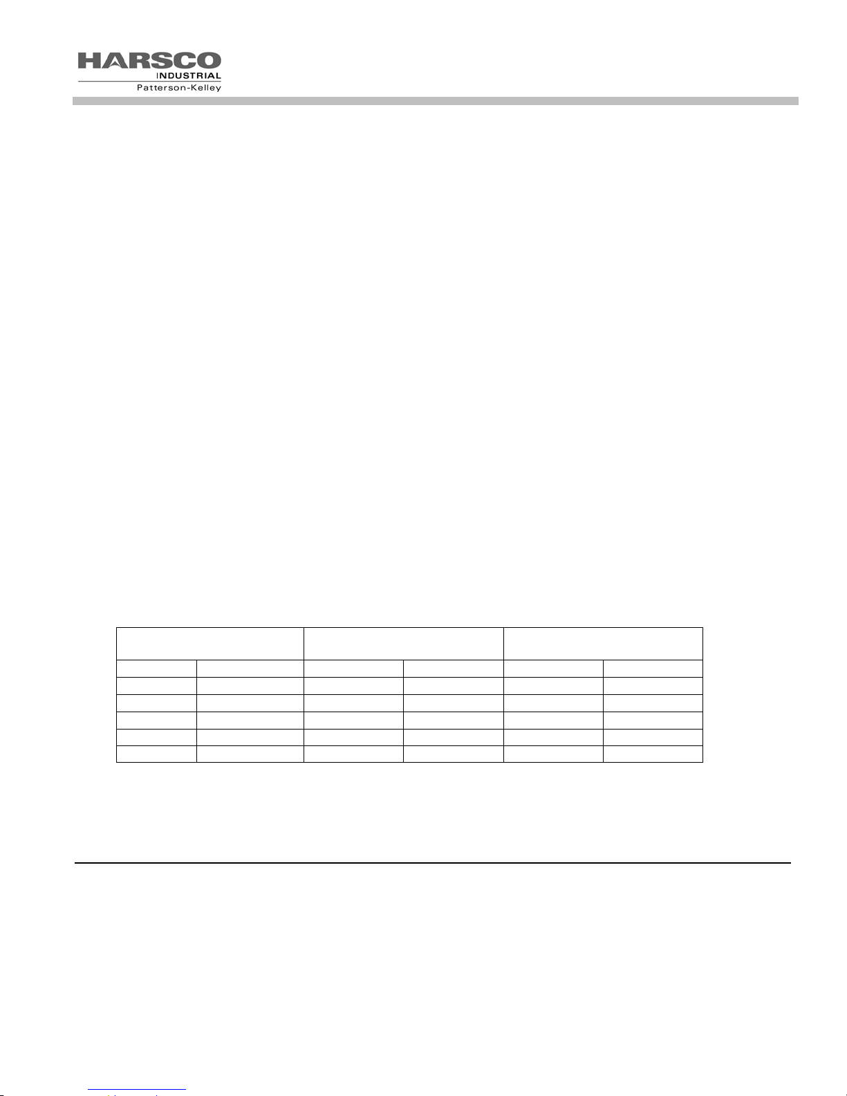
Table of Vent Design Parameters
®
MACH
Boiler Model
C1500H/ C2000H/C2500
C3000/C4000
Frictional
Resistance
0.22” W.C. 220 °F 9.2% 10.4%
Stack
Temperature
CO2 Natural Gas CO2 LP Gas
Do not use a barometric damper with this boiler when installed with Category IV
venting. Positive exhaust pressure may exist which may leak flue gases into the room.
All boiler venting systems should be designed by a qualified venting professional
experienced in venting system design. The information contained herein should be used as a guide only and is not
intended to be used in lieu of qualified technical expertise.
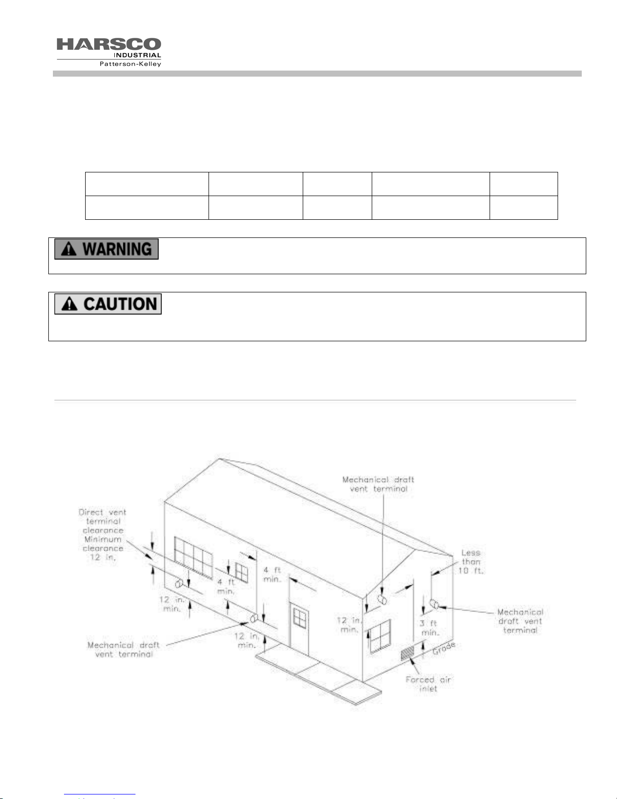
3.5.3.2 Required Clearances
Provide clearances between combustion air intake, exhaust vent, roof and wall surfaces, doors and window, and
snow line. Refer to Figure below: Termination Clearances – Forced Draft and Direct Vent Installations.
Reference: NFPA 54/ANSI Z223.1 National Fuel Gas Code
23
MACH
®
Gas Fired Boiler
Do not locate intake or exhaust terminations directly above a walkway; dripping of
condensation can cause icing of the walking surface. Maintain a minimum clearance of 6 ft (1.83 m) horizontally from
any electric or gas meter, regulator or relief equipment.
Conventional Vent Systems Clearances
The following termination clearance requirements are for conventional, non-direct vent installations.
The vent system shall terminate at least 3 ft above a forced air inlet that is within 10 feet horizontally. As this is a
minimum, your application requirements need to be considered.
The vent system shall terminate at least 4 ft below, 4 ft horizontally from or 1 ft above any door, operable window
or gravity inlet into any building. The bottom of the vent terminal shall be at least 12 in. above grade or highest
expected snow line (if applicable). When deciding on the vent termination consider visibility of the products of
combustion.
Through the wall terminations shall not terminate over public walkways or over an area where condensate or
vapor could create a nuisance or hazard or could be detrimental to the operation of regulators, relief valves or
other equipment.
Direct Vent (Sealed Combustion) Systems Clearances
The vent termination shall be located at least 36 in. from any air opening into a building. The bottom of the vent
termination shall be at least 12 in. above grade. Both the vent and air intake terminations must be at least 12 in.
above the highest expected snow line.
Through the wall terminations shall not terminate over public walkways or over an area where condensate or
vapor could create a nuisance or hazard or could be detrimental to the operation of regulators, relief valves or
other equipment.
When multiple direct vent appliances are adjacent, the exhaust must terminate at least 10 feet horizontally or
three feet vertically above the air intake of another appliance.
Interior Component Clearances
All vent system components shall be installed so as to maintain the following required minimum clearances:
Combustible Non-Combustibles
Unlisted single wall metal pipe Do NOT Use Do NOT Use
Single wall CPVC pipe sch. 80 Per manufacturer’s listing Per manufacturer’s listing
UL 1738 listed Category IV vent Per manufacturer’s listing Per manufacturer’s listing
NOTICE! Make sure that the weight of the vent is not supported by the boiler vent collar. The collar is not
designed to support the weight of the vent. Horizontal vent sections shall be supported in a manner to prevent
sags or low spots where condensate can collect. Structural supports must be connected to building elements of
sufficient strength to withstand the weight of the vent system and any bending forces imposed by the venting system.
ATTENTION! Assurez-vous que le poids de l'évent n'est pas pris en charge par la chaudière évent le collier. Le
collier n'est pas conçu pour supporter le poids de l'évent. Aération Horizontal sections doivent être pris en
charge de manière à éviter les affaissements ou points bas où les condensats peut collecter. Supports de structure
doit être connecté pour éléments de construction d'une résistance suffisante pour supporter le poids du système
d'aération et les forces de torsion imposées par le système de ventilation.
24
MACH
3.5.3.3 Flue Connection
®
Gas Fired Boiler
When applying a
Category IV vent system, the boiler vent should not
be connected into any portion of another mechanical
draft system without consulting the vent
manufacturer. The boiler shall not be connected to
any part of a vent system serving a Category I or II
appliance, nor shall a Category I or II appliance be
connected to any part of the vent system serving this
appliance. Improper interconnection of venting
systems may result in leakage of flue gases into
occupied spaces.
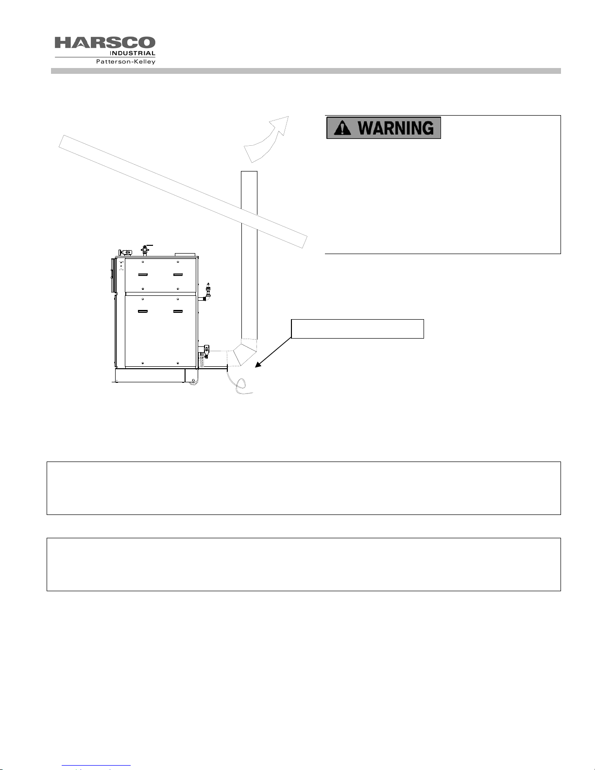
The connection from the boiler to the vent should be
as direct as possible and the upward slope of any
horizontal breaching should be at least 1/4 inch per
linear foot.
4” Tall Condensate Trap
The complete vent exhaust with drain system is shown in the figure (above, as vent is drained separately). The boiler
vent adapter (provided) is designed to accept standard nominal vent pipe sizes. This connector incorporates
provisions to drain condensate formed in the vent system using a 3/4” OD drain stub. This vent drain stub can be
either piped to the condensate drain on the boiler or drained separately. The condensate drains shall have a 4” tall
trap to prevent the passage of flue gases through the condensate system if drained separately.
NOTICE! The condensate formed from combustion flue gases is acidic and has the ability to corrode. The
condensate shall be drained in accordance with local code requirements. A condensate neutralizer may be required
by local code.
Reference: NFPA 54/ANSI Z223.1 National Fuel Gas Code
ATTENTION! Le condensat formé à partir des fumées de combustion est acide et a la capacité de se corroder. Le
condensat doit être drainé, conformément aux exigences du code local. Un neutraliseur de condensats peut être
requis par le code local.
Référence: National Fuel Gas Code, ANSI Z223.1/NFPA 54 et (ou) les codes d’installation CAN/CSA B149.1.
25
MACH
®
Gas Fired Boiler
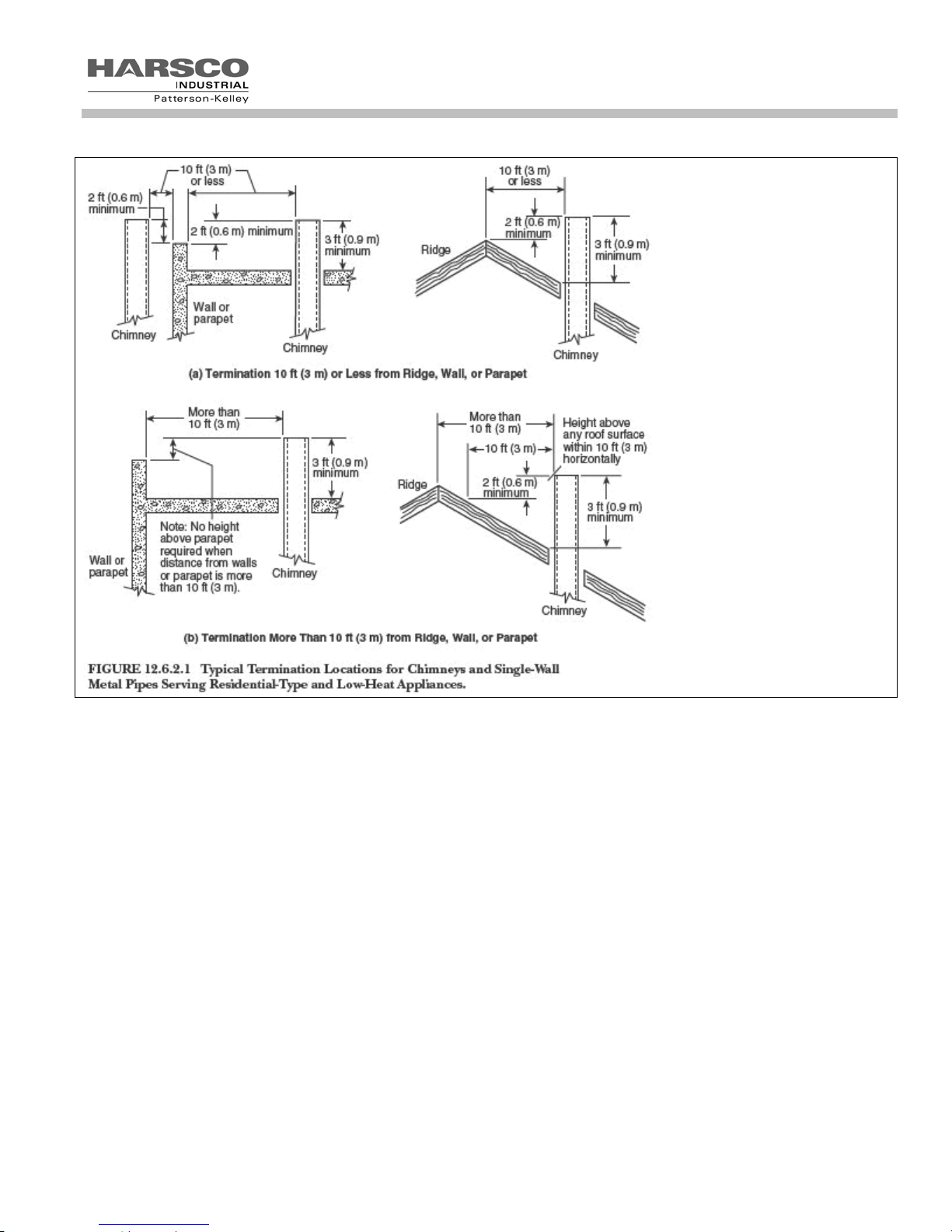
3.5.3.4 Vent Terminations
The vent shall extend at least three (3) feet above the roof, or at least two (2) feet above the highest part of any
structure within ten (10) feet of the vent. This is illustrated in the following diagram.
Additionally the boiler vent shall terminate at least 3 ft above a forced air inlet located within 10 ft.
To prevent the possible re-circulation of flue gases, the vent designer must take into consideration such things as
prevailing winds, eddy zones, building configurations, etc. Harsco Industrial, Patterson-Kelley cannot be responsible
for the effects such adverse conditions may have on the operation of the boilers. Dimensions listed above are
minimums and may not be sufficient for conditions at a specific job site.
Vertical vents are allowed to be terminated with a variety of ends, including plain straight pipe, elbow or vent tee.
Horizontal vents must be terminated as illustrated in section 3.5.5. A bird screen with 1” x 1” openings is
recommended for the termination. Harsco Industrial, Patterson-Kelley does not recommend using a vent rain cap of
any type.
3.5.4 Venting for Multiple Boilers
While the vent design parameters outlined in Section 3.5.3 still apply, achieving those same parameters in a
combined vent system, adds a significant degree of complexity. Therefore, venting systems for multiple boilers shall
be designed by experienced and knowledgeable venting professionals. The venting system shall be designed to
prevent backflow of exhaust gas through idle boilers. It is also recommended that combined venting designs be
limited to no more than four (4) boilers per combined breeching.
26
 Loading...