

Page 1
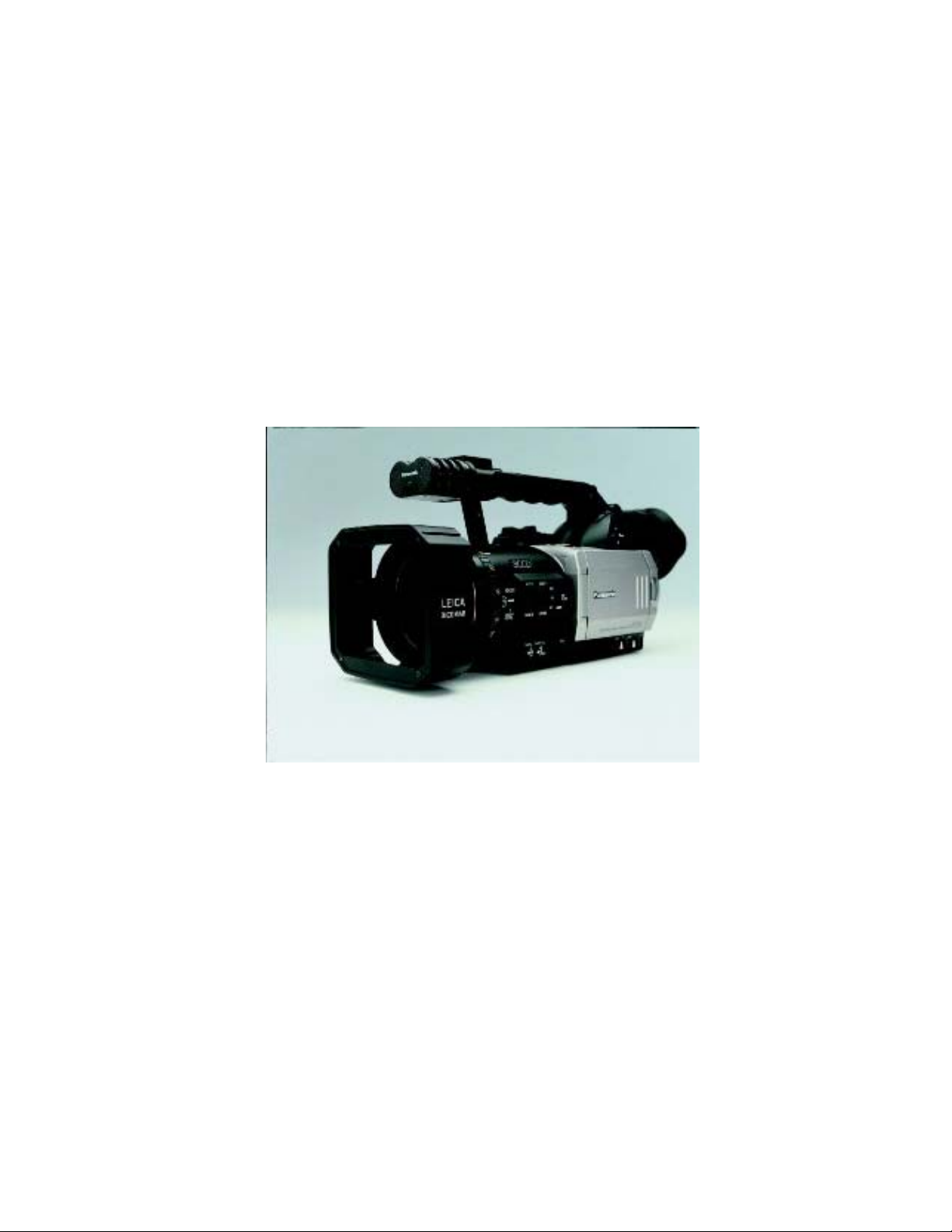
Panasonic’s
AG-DVX100
Set-up Menus
Panasonic Broadcast & Television Systems Company
Page 2

The AG-DVX100 Setup Menus
A guide for getting the most from your
60i, 30p, 24p Camcorder
By
Harry W. Foulds
Panasonic Broadcast & Television Systems Company
Copyright 2003
2
Page 3

Table of Contents
1. Introduction 4 - 8
2. How to use the Menus 9 - 10
3. Quick Menu Index 11 -13
4. CAMERA MENUS
4.1 SCENE FILE 14 - 17
4.2 CAMERA SETUP
4.3 SW MODE
4.4 AUTO SW 20 - 21
4.5 RECORDING SETUP 21 - 23
4.6 DISPLAY SETUP
4.7 OTHER FUNCTIONS 27 - 29
5. VCR MODE MENUS
5.1 PLAYBACK FUNCTIONS 30
5.2 RECORDING SETUP 31 - 32
5.3 AV IN/OUT SETUP
5.4 DISPLAY SETUP
5.5 OTHER FUNCTIONS 34 - 35
6. Glossary 36 - 42
18
19 - 20
24 - 26
33
33 - 34
3
Page 4

Introduction
The AG-DVX100 has captured the imagination of creative filmmakers, broadcasters, and
video professionals around the world, with its 24p (progressive) capabilities.
Panasonic has won a total of 15 Emmys, 12 of them for advancements in the area of digital
video technology. Panasonic’s engineers are continuously pushing the limits of product design and the AG-DVX100 is a prime example of their innovation and imagination.
What is 24p?
Lets start with film, which is shot at 24 frames per second. Inherent in this capture rate, is a
motion blur that is used by the artistic filmmaker to draw the attention of the viewer to his
subject. In the movie theater, film is projected at 48 frames per second due to a shutter in
the projector. The AG-DVX100 uses an electronic shutter which the user can set to different speeds.
“When you watch 24p, you know you are being told a story”. It’s a different look. It’s the
difference between the look of a soap opera or the six o’clock news and the look of a feature film.
There is a three part answer to what must be done to create the cinematic look in video
What is Cine Gamma?
Fact: The contrast ratio of film is greater than contrast ratio of video. Can the range of
bright to dark areas be correctly exposed in a scene? Video has been optimized for high
ambient lighting during image capture (studio) and viewing (living room). Therefore image
brightness has a been much more important than contrast ratio. Film, when used in cinematic presentations, has a very high wide dynamic range providing great detail in both the
brightest and darkest areas of the image. The Cine-like Gamma feature of the AG-DVX100
emulates this wider exposure range characteristic and with the recommended 1/2 f-stop
under exposure should help to maintain increased highlight handling abilities.
What is Progressive?
Rather than capturing one half of a picture (the odd lines) and 1/60th of a second later capturing the second half of the picture (the even lines), wouldn't it be better to capture an entire frame of video with no temporal (time) difference? Progressive recording does accomplishes this! What progressive recording does is creates a picture with double the scan
lines of a conventional interlaced picture, to create a noticeably sharper image.
What is 24p Playback?
If you made a recording in 24p or 24p advanced and now you want to play it back
on a standard NTSC video monitor. The AG-DVX100
version circuit so that you can playback your 24p recordings on a NTSC Monitor. There are
two different schemes used in the AG-DVX100,
use a 2:3 pulldown scheme and in 24p Advanced mode we use 2:3:3:2. This is actually a
method of mapping the 24p into the 30 frames per second NTSC standard video. See the
next page for additional details.
2:3 and 2:3:3:2
has a built in “telecine” or con-
. In 24p playback mode we
4
Page 5
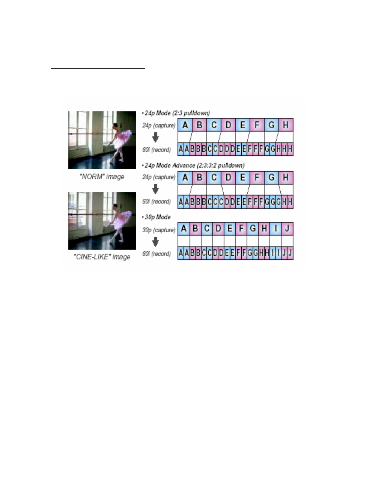
What is 24p Playback?
Here is a graphical view of what is taking place when we playback our 24p recorded video.
Con’t
5
Page 6

Main Features
New CCD Imaging System
Exceptional picture quality, due to a new 1/3 inch, three CCD progressive imaging system
that has 410,000 pixels per chip. This new system was developed specifically for broadcast
and professional applications. These new CCD’s are able to record light as low as three
lux, enabling the shooter to record nighttime events in good detail. The picture quality is
outstanding, with a high signal- to- noise ratio and low smear in bright areas.
Newly developed Zoom Lens
The DVX100 uses a Leica Dicomar ™ lens which incorporates the optical technology of
Leica Camera AG. This lens system employs 15 lens elements in 11 groups, including two
aspherical lenses, to render a shaper image. A Leica multicoating process is applied to the
lenses to reduce flare and ghosts. The 10X zoom has been designed to increase the lens’
wide-angle (f=4.5 to 45mm) capabilities. The zoom lens utilizes a cam-driven manual zoom
ring, with quick, nimble manual zooming as well as a multi-speed servo driven zoom rocker
switch, plus a three-speed handle zoom.
Optical Image Stabilizer Compensates for Hand Held Production
Incorporated in the DVX100 is an OIS (Optical Image Stabilizer) that compensates for slight
hand shaking that may occur when shooting handheld.
A gyrosensor detects handshake and sends signals to a linear motor, which adjusts the lens
to compensate. This process takes place prior to the CCD image capture rather than in the
downstream electronic processing, this minimizes any effect of handshake.
World’s First DV 24p Mode and Cine-Like Gamma
The DVX100 is the world’s first handheld camera designed with video & cinema looks. You
have a choice of three shooting modes, which are selectable, 24p (24 fps progressive) for
images with a movie-like look and motion, 30p (30 fps progressive) or standard 60i (60 fps
interlaced). Images that are captured in 24p mode, Re converted to either 2:3 (24p Mode)
or (24p Advanced) with a 2:3:3:2 pulldown sequence. And recorded onto the video tape in
the standard 60i Video format, which allows for playback on an ordinary DV VCR and TV
monitor and edited on a DV system.
6
Page 7
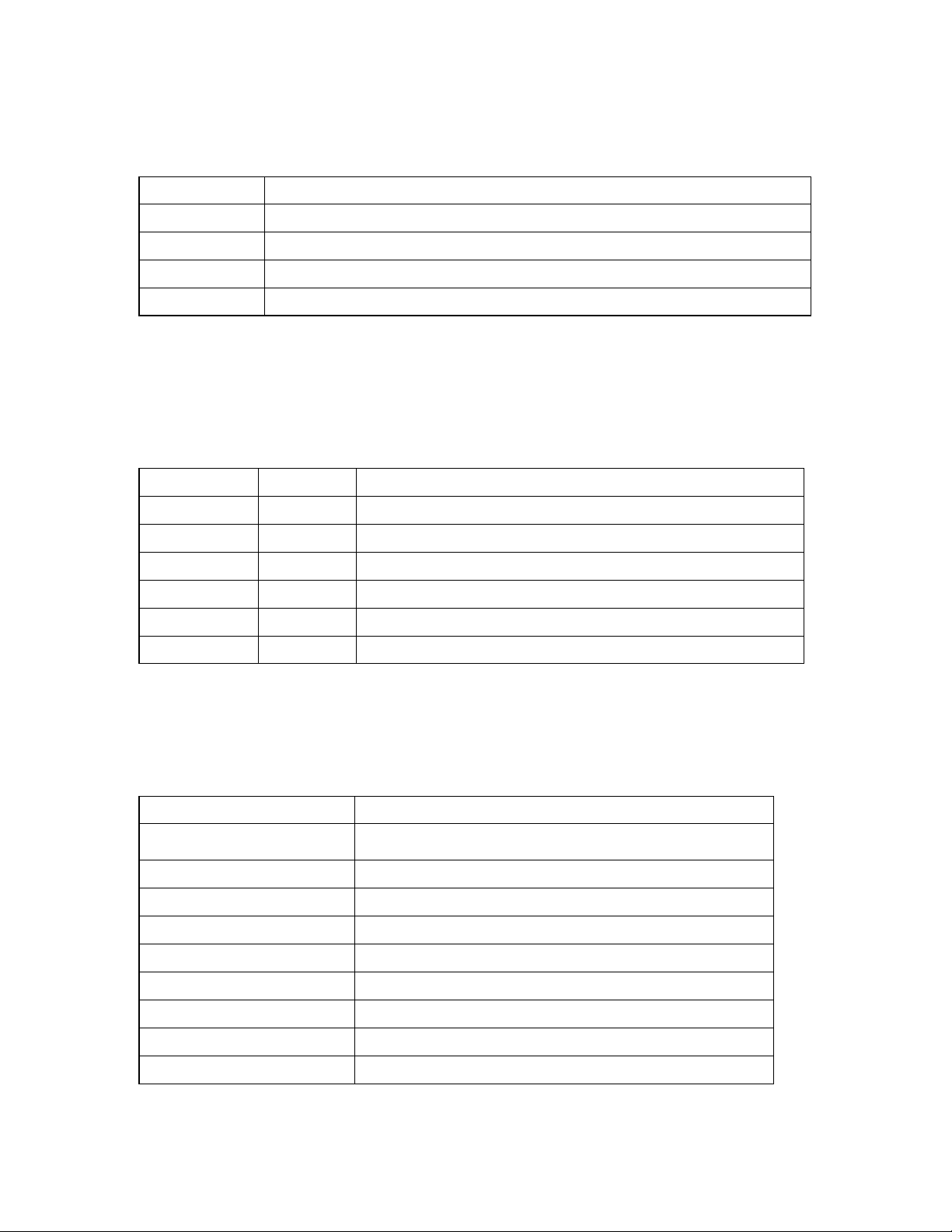
The Gamma settings menu curve allows you to select from four gamma curves:
Gamma Image
CINE-LIKE Film-like images
LOW Images with strong black contrast
NORM Standard video gamma
HIGH Bright images with enhanced gradation in dark areas and soft contrast.
Scene File Dial for Quick, Easy Camera Setup
The scene file dial which is located on the back of the camcorder sets up a variety of
shooting conditions, and later you can instantly retrieve the settings for future use. Six
suggested preset files are provided (F1 to F6) by the factory . You can freely change
any of the six file names and their settings.
Scene File Name Function
F1 ------- Standard settings
F2 FLUO Indoor shooting under fluorescent lights
F3 SPARK Events increase color and Detail
F4 B-STR Enhanced gradation in dark areas of sunset shots
F5 24P 24p mode + Cine-Like gamma
F6 ADVANC Advanced 24p mode + Cine-Like gamma
User1 / User2 Buttons for Customized Operation
The DVX100 provides two user buttons, each of which can be assigned any one of the
nine functions described below. These assigned functions can then be accessed at the
touch of a button.
Items Assignable Functions
COLOR BAR
SPOTLIGHT Turns auto iris spotlight on / off
Display / hide the SMPTE color bars
(Not in progressive mode)
BACKLIGHT Turns auto iris backlight compensation on/off
BLACKFADE Fade out to black / with audio
WHITEFADE Fade out to white / with audio
MODECHECK Display camera settings in viewfinder
ATW Turns auto tracking white balance function on/off
ATWLOCK Lock/unlock white balance in ATW operation
GAIN 18 dB Switches the gain to +18dB (Not in progressive mode)
7
Page 8

Built-In SMPTE Time Code Generator and Reader
The DVX100 records SMPTE- compliant VITC onto the Sub-code area of the videotape.
Select from DF / NDF and Free Run/Rec Run modes, and use a preset or regen. User bits
(UB) are also provided, letting you record your choice of date, time, TC value, frame rate or
user data. In 24p the time code is in NDF mode only.
IEEE 1394 terminal for non-linear production with Synchro Lock Function
Equipped with an IEEE 1394-compliant 4-pin DV terminal that makes it easy to upload data
to a PC and dub onto a DV recorder. This terminal also features a new synchro lock function that allows the AG-DVX100 to remotely start and stop an external DV device connected
to it via a DV cable, such as the AG-DV1DC portable mini-DV recorder.
XLR Audio Input with +48 Volts Phantom Power Supply
In addition to a built-in stereo microphone, the DVX100 is equipped with two XLR audio input connectors with switchable +48 volts phantom power. Both input 1 and Input 2 can be
switched between line and mic with hard switches at the front of the camcorder. Auto gain
level can be turned on and off, and the input mic level (-50dB / -60 dB) can be selected from
the menu to ensure proper matching to an external MIC output or the environment.
The DVX100 has more special features that will make the Broadcaster or professional
shooter’s job much easier.
In order to properly control this camera for generating the most powerful video images,
more operators should understand camera process terminology.
Experienced camera operators know there are always tradeoffs in every shooting situation.
You’ll trade shutter speeds for depth of focus, resolution for sensitivity, detail for noise, and
the list goes on. The DVX100’s extensive menu system will provide the camera operator
with additional tools for more creative solutions for image capture.
The following menu descriptions show diagrams of these menus and explain the effects of
each setup function.
8
Page 9
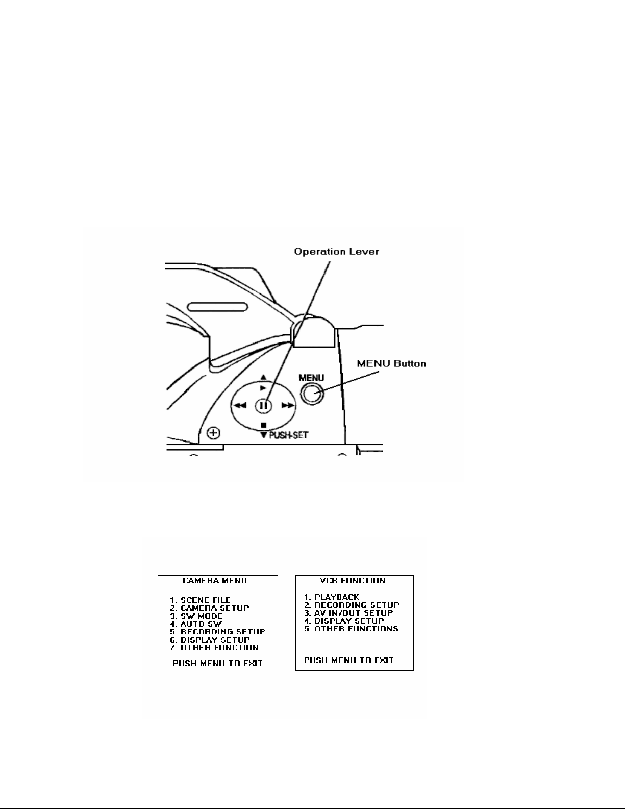
How to use the Setup and operator Menus
The DVX100 offers the operator an extremely flexible setup capability.
There are basically two groups of menus, one for Camera functions and the other for VCR
Functions. These two groups give you the opportunity to choose from 73 items. Some of
the menu items are used jointly in the camera and the VCR.
In order to access the menus, first make sure you are not in the record mode. Choose the
camera or VCR mode, by pressing the Camera/VCR button located on the lower back section of the camcorder. Now press the menu button located near the viewfinder marked
MENU.
Once you pressed the MENU button, the menu will appear in the EVF and also on the LCD
screen depending on where the DISPLAY menu is set. (EVF ON / OFF)
9
Page 10

The operator may now change the menu by using the Operation Lever in the up direction
S or down direction T. This will highlight each selection, one at a time. Highlight any
function that you would like to change. Now press the Operation lever like a button, and
this will display the items in that menu selection. To chose the item in this menu, once
again press the Operation Lever in the up direction S or down direction T. To pick your
selection press the Operation Lever and this will move the on screen arrow to the selection you want. Now that you have made your selection Press the MENU button two times
to exit the menu and return to a normal screen. There is no set button; merely choosing
the item then pressing the menu button twice will effect the change.
Note:
You can not operate the menu system while you are recording.
10
Page 11
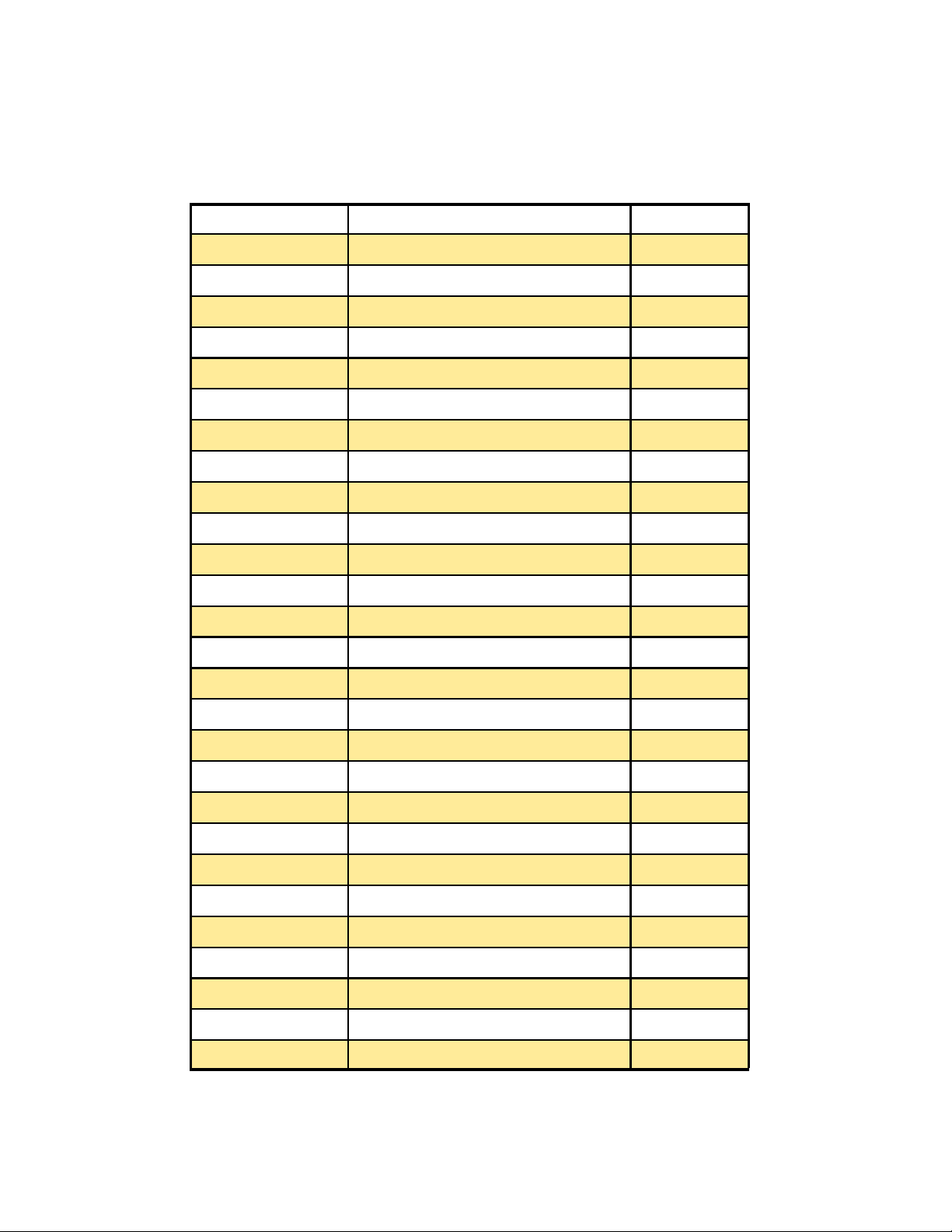
AG-DVX100 Menu Index
12 bit Audio Playback Functions Screen (VCR) 30
1394 TC Regen Recording Setup Screen (VCR) 31
1394 UB Regen Recording Setup Screen (VCR) 32
A Dub Input AV In/Out Setup Screen (VCR) 33
A Iris Level Scene File Screen (Camera) 16
A Iris Auto SW Screen (Camera) 20
AF Auto SW Screen (Camera) 21
AGC Auto SW Screen (Camera) 20
Aspect Conv Camera Setup Screen 18
ATW SW Mode Screen (Camera) 19
ATW Auto SW Screen (Camera) 21
Audio Out Playback Functions Screen (VCR) 30
Item Menu Page
Audio Rec Recording Setup Screen (Camera) (VCR) 22, 31
Beep Sound Other Functions Screen (Camera) 28
Camera Date Display Setup Screen (Camera) 25
Chroma Level Scene File Screen (Camera) 15
Chroma Phase Scene File Screen (Camera) 15
Clock Set Other Functions Screen (Camera) (VCR) 28, 35
Color Bar Camera Setup Screen (Camera) 18
Color Temp Scene File Screen (Camera) 15
Date/Time Display Setup Screen (Camera) 25, 33
Detail Level Scene File Screen (Camera) 15
DV CMD Set Other Functions Screen (Camera) 28
DV Control Other Functions Screen (Camera) 27
DV Out AV In/Out Setup Screen (VCR) 33
End Search Playback Functions Screen (VCR) 30
EVF Mode Display Setup (Camera) 26, 34
11
Page 12
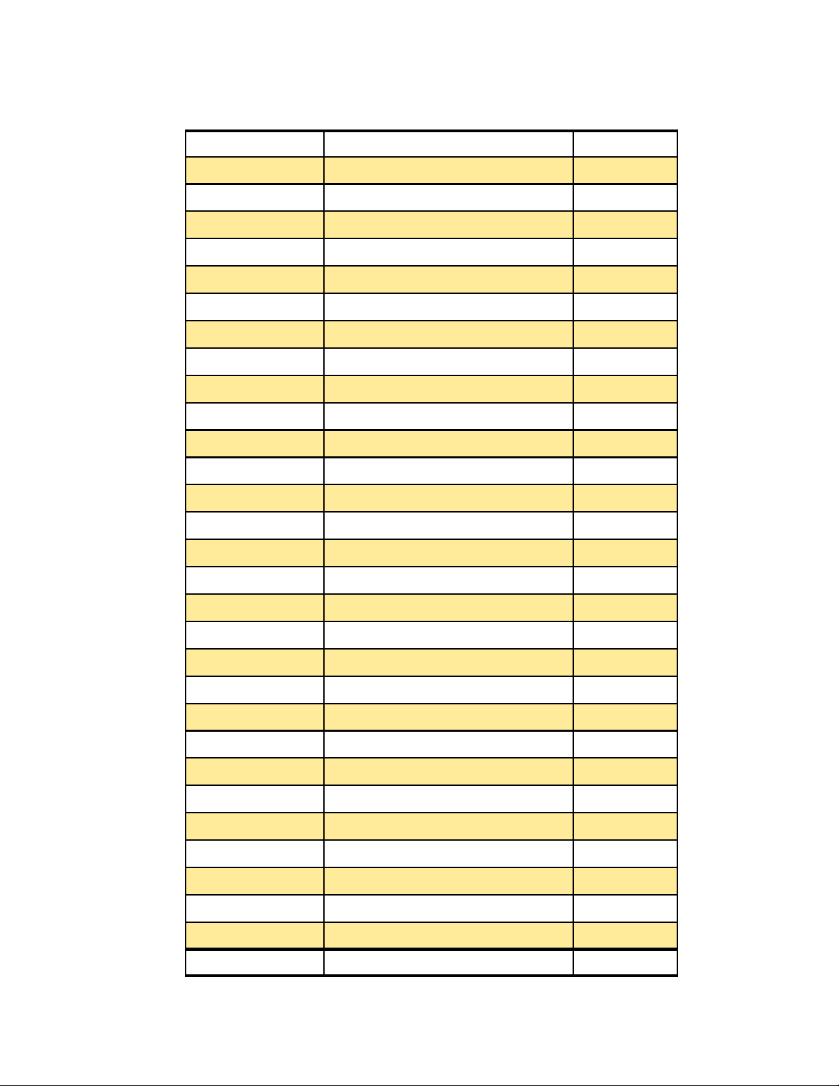
Item Menu Page
First Rec TC Recording Setup Screen (Camera) (VCR) 23, 32
Gamma Scene File Screen (Camera) 16
Handle Zoom SW Mode Screen (Camera) 19
High Gain SW Mode Screen (Camera) 19
Hour Meter Other Functions Screen (Camera) (VCR) 29, 35
Interval Rec Recording Setup Screen (Camera) 23
Interval Time Recording Setup Screen (Camera) 23
Iris Dial SW Mode Screen (Camera) 20
LCD / EVF Set Display Setup Screen (Camera) (VCR) 26, 34
LCD Backlight Display Setup Screen (Camera) (VCR) 26, 34
Level Meter Display Setup Screen (Camera) (VCR) 25, 34
Master Ped Scene File Screen (Camera) 16
Marker Display Setup Screen 25
Matrix Scene File Screen (Camera) 16
Mic ALC Recording Setup Screen (Camera) 22
Mic Gain 1 Recording Setup Screen (Camera) 22
Mic Gain 2 Recording Setup Screen (Camera) 22
Mid Gain Scene File Screen (Camera) 19
Name Edit Scene File Screen (Camera) 17
Other Display Display Setup Screen (Camera) (VCR) 25, 34
Progressive Scene File Screen (Camera) 17
Rec Lamp Other Functions Screen (Camera) 28
Rec Speed Recording Setup Screen (Camera) (VCR) 21, 31
Rec Time Recording Setup Screen (Camera) 23
Remote Other Functions Screen (Camera) (VCR) 27, 34
Save / Init Scene File Screen (Camera) 17
Self Shoot Display Setup Screen (Camera) 26
Setup Camera Setup Screen 18
Skin Tone DTL Scene File Screen (Camera) 16
Syncro Scan Camera Setup Screen 18
12
Page 13
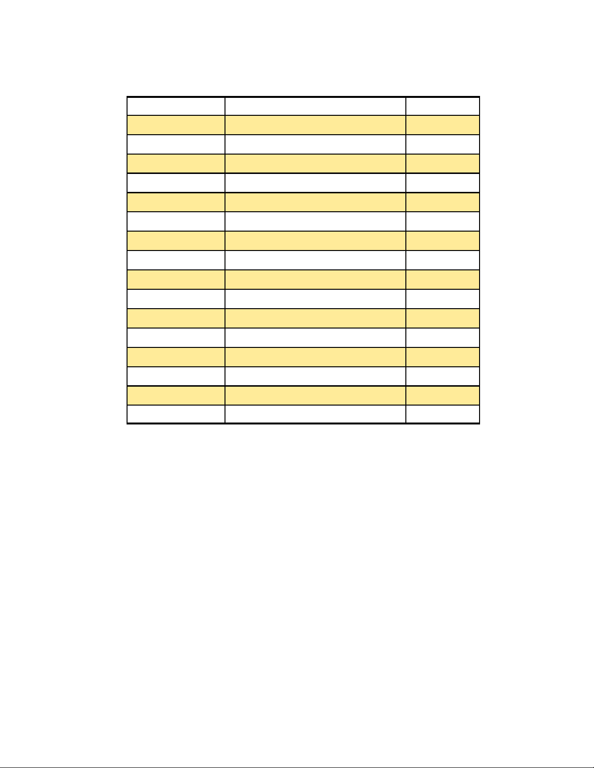
Item Menu Page
Tape Protect Other Functions Screen (Camera) 29
TapeyBattery Display Setup Screen (Camera) (VCR) 25, 34
TC Mode Recording Setup Screen (Camera) (VCR) 22, 31
TC Preset Recording Setup Screen (Camera) (VCR) 23, 32
TCG Recording Setup Screen (Camera) (VCR) 22, 32
Time Shift Other Functions Screen (Camera) (VCR) 28, 35
UB Mode Recording Setup Screen (Camera) (VCR) 23, 32
UB Preset Recording Setup Screen (Camera) (VCR) 23, 32
User 1 SW Mode Screen (Camera) 20
User 2 SW Mode Screen (Camera) 20
User File Other Functions Screen (Camera) (VCR) 29, 35
V Detail Freq Scene File Screen (Camera) 17
Video Out OSD Display Setup Screen (Camera) 25, 34
Zebra Detect 1 Display Setup Screen (Camera) 24
Zebra Detect 2 Display Setup Screen (Camera) 24
ZoomyFocus Display Setup Screen (Camera) 25
13
Page 14
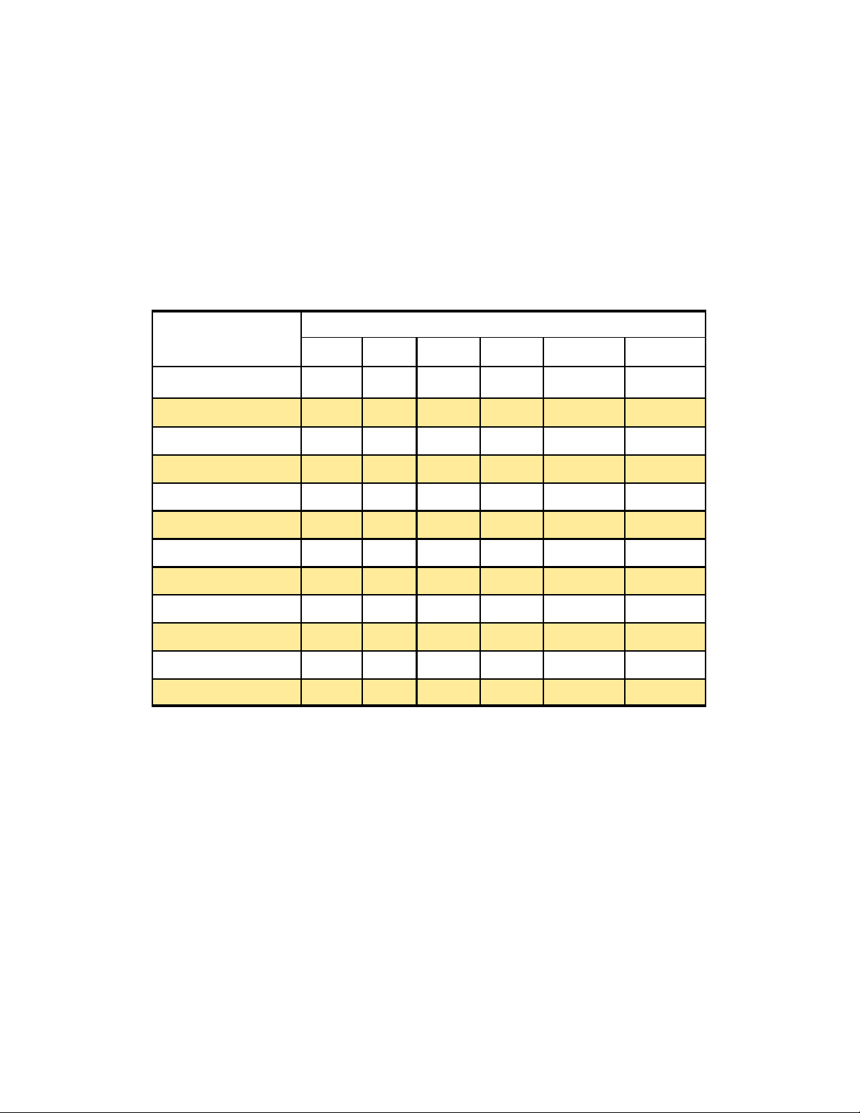
4 . Camera Menus Screen
4.1 Scene File Screen
The Scene File Menu allows the user to quickly change the setup for up to six scenes with a
turn of the scene dial.
The scenes are tailored to various shooting conditions and are stored in the six menu
memories and are selected by a six position rotary dial (cine switch), located at the back of
the camcorder. You may also set up your own scene files instead of using the factory defaults.
Factory Defaults for
DETAIL LEVEL 0 0 + 5 0 - 4 0
CHROMA LEVEL 0 + 2 + 3 + 3 0 0
CHROMA PHASE 0 0 0 0 0 0
COLOR TEMP 0 0 0 0 0 0
MASTER PED 0 0 -3 - 1 -5 -5
A. IRIS LEV 0 0 0 - 1 - 3 - 3
GAMMA NORM NORM LOW HIGH CINE-LIKE CINE-LIKE
SKIN TONE DTL OFF OFF OFF OFF OFF OFF
MATRIX NORM NORM NORM NORM CINE-LIKE CINE-LIKE
V DETAIL FREQ THICK THICK THICK THICK THICK THIN
PROGRSSIVE OFF OFF OFF OFF 24P 24P(Adv)
Items ——— FLOU. SPARK B-STR 24P ADVANC
F1 F2 F3 F4 F5 F6
The factory defaults are set up for six different scenes:
F1 : SCENE This file contains the settings suited for standard recording.
F2 : FLOU
F3 : SPARK
This file contains the settings suited for recording under fluorescent lights.
This file contains the settings suited to accentuating the subject while
recording (for shooting a wedding reception, etc.)
F4 : B-STR
This file contains the settings suited for recording with extended
gradations in the dark areas (for recording scenes at dusk, etc.)
F5 : 24P This file contains the settings suited for recording in the progressive 24P
mode
F6: ADVANC This file contains settings suited for recording in progressive 24p
advanced mode.
Note:
During recording, you can not change the scene file to progressive. You must be
in the record standby mode to change to the progressive mode.
Defaults for Scene File Dial
14
Page 15
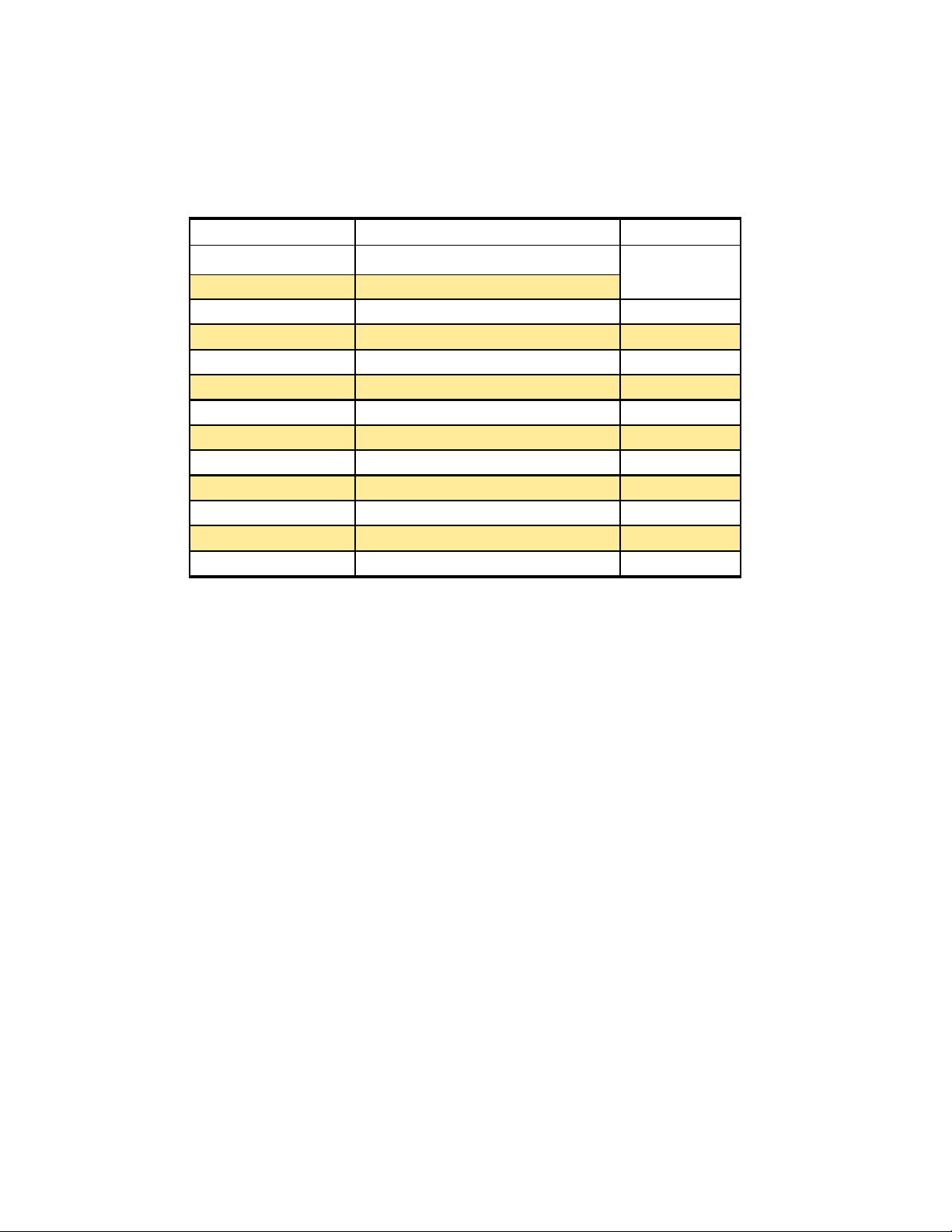
As was explained the scene files are set to factory defaults, but they may be also tailored to
your various shooting conditions and stored in the menu memories and you may select
them with a six position rotary dial (cine switch), located at the back of the camcorder.
DETAIL LEVEL -7 to +7
CHROMA LEVEL -7 to +7
CHROMA PHASE -7 to +7
COLOR TEMP -7 to +7
MASTER PED -15 to +15
A IRIS LEVEL -4 to +4
GAMMA CINE-LIKE, LOW, NORM, HIGH
SKIN TONE DTL ON / OFF
MATRIX NORM, FLOU, CINE-LIKE
V DETAIL FREQ THIN / THICK
PROGRESSIVE OFF, 30P, 24P, 24(ADV)
NAME EDIT NAME
SAVE / INIT SAVE INITIAL
Item Settings Default
See Page 14 for
all actual Factory
Defaults settings
Detail Level
allow you to increase or decrease the overall Horizontal and Vertical detail in the picture.
Changing the detail level will affect the whole picture, this adjustment will
Chroma Level
of color that is in the video image.
Changing the Chroma Level allows you increase or decrease the amount
Chroma Phase
(tint) of the video image. Keep in mind that this adjustment is a fine adjustment.
Color Temp
up and emits a light which has a certain spectral response. For example, at 3000 degrees
Celsius carbon black emits a light. The color temperature of that light is said to be 3200
Kelvin (3000 Celsius equals 3200 Kelvin). Color temperature generally expresses chromaticity of a source of light such as indoor or outdoor light. For example, if the temperature is
relatively low, the light appears reddish. As the temperature increase, the light changed
from red to orange to yellow to white. So when a camera is used with light whose color
temperature is other than 3200K, use the appropriate color temperature conversion filter or
setting. The color Temp setting allow you to finely adjust the color temperature, after the
white balance has been adjusted.
Changing the Chroma Phase allows you to change the phase of the color
Color temperature is determined at the temperature when carbon is heated
15
Page 16

Master Ped
in digital video it is set at 0 IRE or 0%, this is the black reference for the video signal. This
adjustment allows the user to slightly control the pedestal level which is set in the Camera
Setup Menu. This will change the black reference for the video signal and allow for either
slightly rising of the blacks or the crushing of them.
In standard analog video the Pedestal is normally set at 7.5 IRE or 7% and
A Iris Level
matically based upon Auto mode selection (IRIS) on the side of the camcorder.
The automatic iris level controls the iris opening or level of the video auto-
Gamma
characteristics of the standard TV picture tube.
and compresses the blacks.
blacks
waveform monitor. Camera gamma must be the reciprocal of picture gamma which is 2.2,
so the camera gamma is usually 0.45.
The DVX100 has four selections for the gamma curve:
Cine-Like
iris about a 1/2 stop lower then standard video settings.
Low
image looks a little sharper due to the change in the gamma curve.
Norm Standard video images are produced.
High This setting allows for a sharp gradient for the low luminance areas, thus the dark ar-
eas are extended to make them appear brighter.
Gamma correction is applied in the camera to correct for nonlinear light-output
Picture-tube gamma
Camera gamma
. Camera gamma can be properly set by using logarithmic gray scale charts and a
This gamma curve gives the video image a cinema like look. Its best to set the
This setting allows for a moderate gradient for the low luminance areas. The video
compresses
the whites and stretches the
stretches the whites
Skin Tone DTL
sion. The
tail is turned on, the facial skin color has its detail reduced smoothing any skin irregularities,
without affecting other areas of the video image.
Matrix
the visible spectrum can be adjusted. We often have to compensate the colors due to lighting conditions.
The DVX100 has three settings:
Norm Used for shooting under halogen lighting in the studio.
FLOU Used for shooting under fluorescent lighting.
Cine-Like
Skin Tone Detail
The mixture of the primary colors red, blue and green to produce the many hues in
Used to produce a richer, cinema like color.
The “talking head is probably one of the most common shots on televi-
is used to improve the head shot quality. When skin tone de-
16
Page 17

V Detail Freq
of the image. This will slightly improve the sharpness of the image.
Used in the progressive mode to increase the detail in the vertical portion
In 24p thick used for
video playback, while the thin setting is used for going out to film.
Progressive
OFF: Progressive video recording is turn OFF, you will be using standard interlace
video (60i).
30P: In this selection you will be recording in the Progressive mode at a 30 frame
per second mode. The 30 frames per second video imaged are converted into 60 f
field interlace signals, and the resulting video signals , and the resulting video
signals are output or recorded. In this mode , high-quality still pictures free of
vertical shifting, can be obtained in this mode
24P: In this selection you will be recording in the Progressive mode at a 24 frame
per second mode, or a Cinema look. The 24P frame per second images are
converted into 60 field interlace signals using 3:2 pulldown or conversion system.
The resulting video signals are output or recorded. Cinema-like images can be ob
-tainted in this mode
24P (ADV):
mode at a 24 frame per second mode. The 24 frames per second video images are
converted into 60 field interlace signal by the advanced 2:3:3:2 pulldown method
and the resulting video signals are output or recorded. Use this setting when the
final product will be transferred to film.
Note: The color bar signal cannot be displayed. The gain cannot be controlled, it is fixed.
The auto focus cannot be utilized. When the progress mode has been selected, the sync
signal may be temporarily disturbed and no video will be output for 3 seconds. A shutter
setting of 1/50 (OFF) or 1/60 is recommended. When using ATW (Auto Tracking White)
function the black balance will not function. Since the video is recorded in 5 frame increments in 24P and Advanced mode, the timing at which recording starts may be slightly delayed.
Name Edit
lected by the scene file dial,
This selection allows you to choose between four selections:
In this selection you will be recording in the Advanced Progressive
This selection allows you to change or edit the name of the scene file se-
Save / Init
or you will revert back to the old settings when power is turned off or you switch to the VCR
mode. If the initial mode is chosen the scene file settings will return to the factory defaults.
Save, allows you to save changes made in a scene file. Remember to do this
17
Page 18
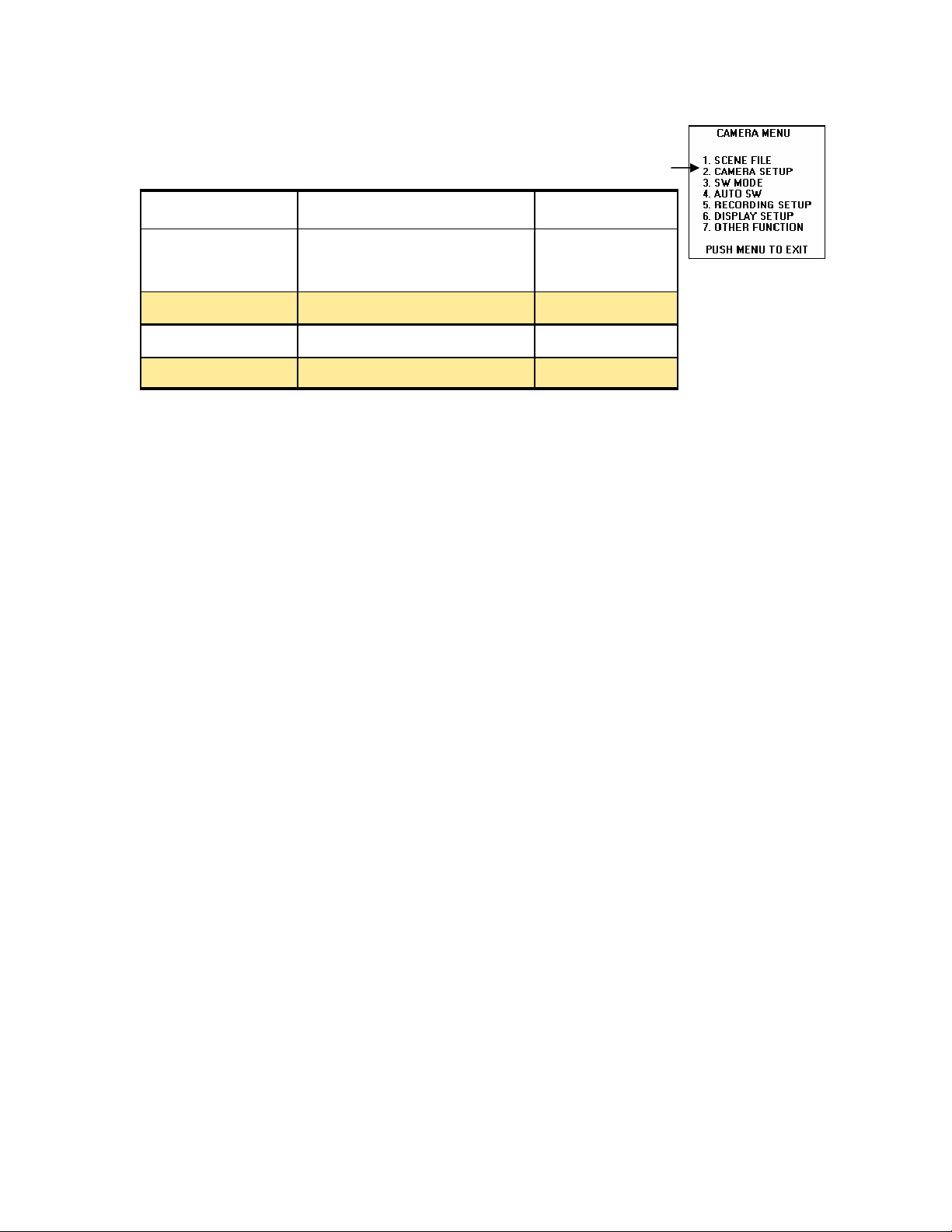
4.2 Camera Setup Menu Screen
Item Settings Default
SYNCRO SCAN OFF : 1/60.3—1/250
30P : 1/30.1—1/250.0
24P/24PA : 1/24.1—1/250.0
OFF 1/60.3
30P 1/48.0
24P& 24PA 1/48.0
ASPECT CONV NORM / LETTER BOX NORM
COLOR BAR ON / OFF OFF
SETUP 0% / 7.5% 0%
Syncro
your computer monitor or television, when you are recording a scene that has either of
these in it. By setting up the correct syncro scan in the menu, you can press the shutter
button on the side of the camcorder and prevent this problem.
What you are doing in the MENU, is trying to synchronize the camera’s shutter with the
scan rate of the computer monitor or television included in the scene.
Scan
Is used to prevent black or white horizontal bars that may appear across
Aspect Conversion
The standard images have an aspect ratio of 4:3. When placed in 16:9 aspect ratio the images are recorded with black bands across the top and bottom of the screen creating the
16 by 9 or letter box image. This method is called letterbox and has the major advantage of
WYSIWYG (What You See Is What You Get). It you use an external anamorphic lens
adaptor, about 25% higher vertical resolution can be obtained which may be more important
for film out applications. If Letterbox is selected, the normal CCD based imager signal output of 720 pixels H by 480 pixels V is cropped down to 720 pixels H by 360 pixels V. The
remaining 60 pixels at the top and bottom of the picture are forced to black. When an external anmorphic lens is used the source image is optically converted from widescreen 16:9
aspect down to a 12:9 aspect (4:3). Therefore the entire surface of the CCD based imager
can be used to capture the image, yielding a full 480 lines of vertical resolution.
Allows you to select the aspect ratio of the image to be recorded.
Color Bars
formance, it also may be used at the beginning of the videotape as a reference.
You can turn this function off or on in this menu. If you leave it on, it will shut off when the
camcorder is placed in the VCR mode or the power is shut off. This function does not work
in the progressive mode.
A SMPTE test signal is generated internally, used to check the cameras per-
Setup Also called pedestal, this is the video black level in a video image, 0% is
the default setting for the DVX-100. Digital Video uses 0% setup (which is the
ITU-R-601 Digital standard setting and Standard analog interlace video uses 7.5%.
18
Page 19
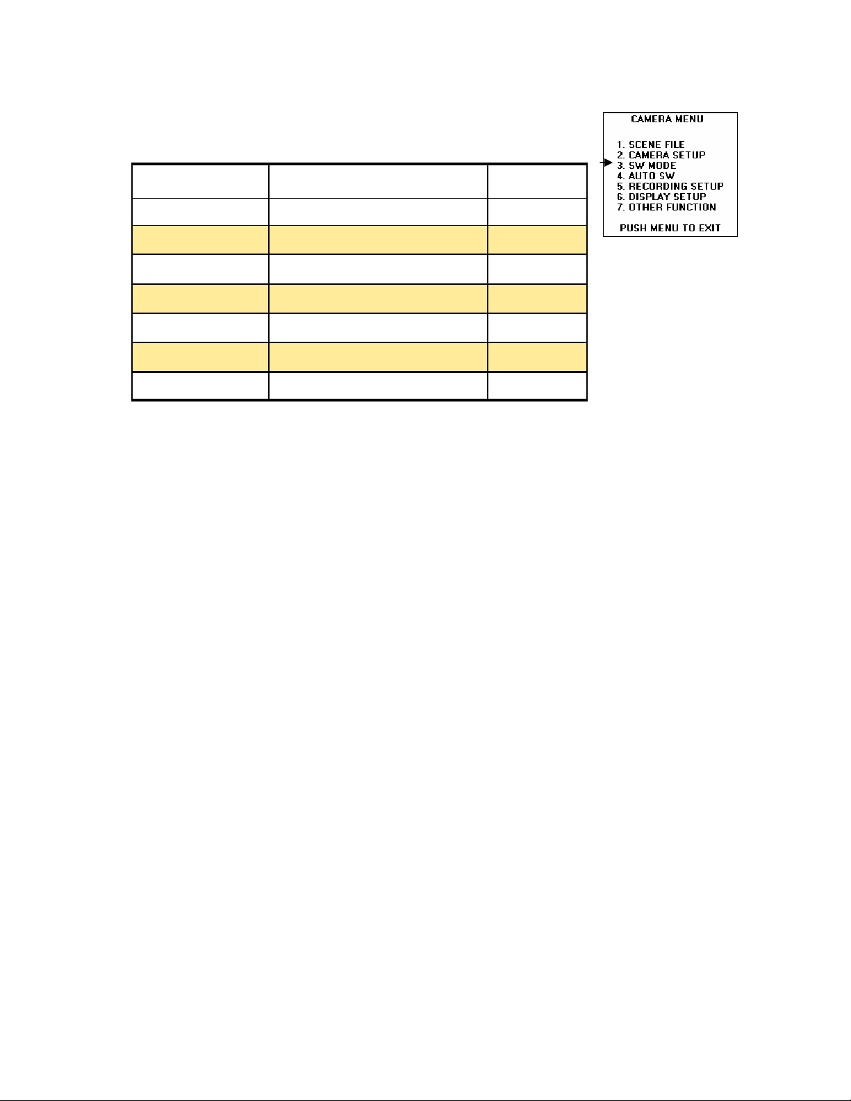
4.3 SW MODE Screen
Item Settings Default
MID GAIN 0dB, 3dB, 6dB, 9dB, 12dB 6 dB
HIGH GAIN 0dB, 3dB, 6dB, 9dB, 12dB 12 dB
ATW OFF, AcH, BcH, PRE OFF
HANDLE ZOOM L, OFF, H L,M,H L/OFF/H
IRIS DIAL DOWN OPEN /UP OPEN DOWN OPEN
USER 1 COLOR BAR YES
USER 2 BACKLIGHT BACKLIGHT
Mid Gain
This item selects the video gain at the M position of the GAIN switch located on the side of the DVX-100. There are five settings you can choose from:
0dB to 12dB. The factory default is set to 6dB.
High Gain This item selects the video gain at the H position of the GAIN switch located on the side of the DVX-100. There are five settings you can choose from:
0dB to 12dB. The factory default is set to 12 dB.
ATW
The Auto Tracking White function, is used during the record mode to continually adjust the
white balance automatically. With this menu item you can assign this function to one of positions of the WHITE BAL switch or turn it OFF.
There are four settings:
OFF: This turns off the ATW function and allows the AUTO button or USER button to take
control.
Ach: Sets the ATW function to Ach position of the WHITE BAL switch.
Bch: Sets the ATW function to Bch position of the WHITE BAL switch
PRE:
Normally, the white balance should be re-adjusted as the lighting conditions change.
Sets the ATW function to PRST (Preset) position of the WHITE BAL switch
Handle Zoom
HANDLE ZOOM switch located on the handle of the DVX-100.
L/OFF/H: Low/ OFF/ High speeds are set to the 1/2/3 positions of the Handle Zoom
switch .
L/M/H: Low/ mid (Medium)/ High speeds are set to the 1/2/3 positions of the Handle Zoom
switch.
This item sets the zoom speeds of the lens, which are controlled by the
19
Page 20
Iris Dial
When set to DOWN OPEN, the iris will open when the IRIS dial is turned down. When set
to UP OPEN the iris will open when the IRIS dial is turned upward.
User 1 & User 2
operations of the DVX100. Each button may be assigned any one of the nine functions
described In the table below. These assigned functions can then be accessed at the touch
of a button.
This item sets the direction of rotation of the IRIS dial in the Manual iris mode.
the User1 and User2 buttons are used for quick access customized
Items (Choose one) Assignable Functions
COLOR BAR Display / hide the SMPTE color bars
SPOTLIGHT Turns auto iris spotlight on / off
BACKLIGHT Turns auto iris backlight compensation on/off
BLACKFADE Fade out to black / with audio
WHITEFADE Fade out to white / with audio
MODECHECK Display camera settings in viewfinder
ATW Turns auto tracking white balance function on/off
ATWLOCK Lock/unlock white balance in ATW operation
GAIN 18 dB Switches the gain to +18dB
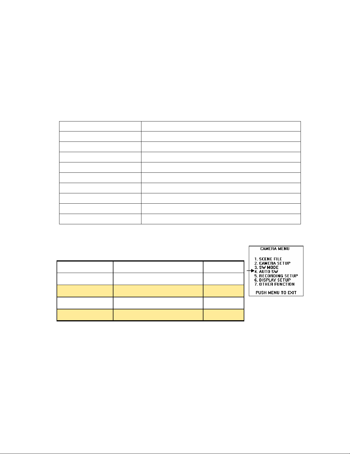
1.3 Auto Sw Screen
Item Settings Default
A IRIS ON / OFF ON
AGC 6dB, 12 dB, OFF 6 dB
ATW ON / OFF ON
AF ON / OFF ON
A. Iris When set to ON, or when the
performed. The IRIS button will not operate at this time. When turned OFF the AUTO iris
control will not function and the IRIS button can be used.
AUTO button is pressed, the auto iris control is
AGC
6dB: When the AUTO button is pressed the video gain will increase by a maximum of
6dB.
12dB:
12dB.
This setting sets the video gain when the AUTO button is used.
When the AUTO button is pressed the video gain will increase by a maximum of
20
Page 21
ATW
change. The Auto Tracking White function, is used during the record mode to continually
adjust the white balance automatically. With this menu item you can turn this function OFF
or ON when the AUTO button is pressed.
AF
the FOCUS switch and PUSH AUTO buttons will not function. When AF is set to the OFF
position, the auto focus operation will not be performed when the AUTO button is pressed.
The FOCUS switch and PUSH AUTO will be functioning. Not in available in progressive
mode
Normally, the white balance should be re-adjusted as the lighting conditions
When set to the ON position, auto focus operates when the AUTO button is pressed,
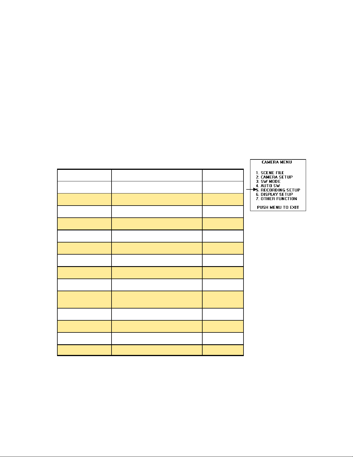
4.4 RECORDING SETUP Screen
(Same Menu used for the VCR, some functions not used)
Item Settings Default
REC SPEED SP / LP SP
AUDIO REC 12 bit / 16 bit 16 BIT
MIC ALC ON / OFF ON
MIC GAIN 1 -50dB, -60dB -50 dB
MIC GAIN 2 -50dB, -60dB -50 dB
TC MODE DF / NDF DF
TCG FREE RUN / REC RUN REC RUN
FIRST REC TC REGEN / PRESET REGEN
TC PRESET Input Start of Time code - - - -
UB MODE USER, TIME, DATE, TCG, FRM
RATE
UB PRESET Setting user’s bit - - - -
INTERVAL REC OFF, ON, ONE-SHOOT OFF
REC TIME 0.5s, 1s, 1.5s, 2.Os 0.5s
INTERVAL TIME 30s, 1m, 5m, 10m 30s
USER
Rec Speed
play or LP for long play. SP is preferred for interchange.
This item allows the user to select the recording time, either SP for standard
21
Page 22

Audio Rec
(16 bit/48kHz). 16 bit audio recording is preferred.
Used for selecting the method of recording audio, 12 bit (12bit/32kHz) or 16 bit
Mic ALC
Microphone.
Mic Gain 1
that is connected to INPUT 1 connector. Either –50dB or –60 dB, see your MIC’s specs.
This item Allows the user to turn ON or OFF the automatic level control for the
This item allows the user to select the input level of the external microphone
Mic Gain 2
that is connected to INPUT 2 connector. Either –50dB or –60 dB, see your MIC’s specs.
This item allows the user to select the input level of the external microphone
Time Code
special internal generator will place an 80 bit code or number on every recorded frame. The
VCR will use this number for precise identification of a frame when editing. This code is recorded with the video and audio signals and is stored in the sub code area on the DV tape.
This code contains the hour, minute, second and frame number.
In the 80 bits of time code you have a lot of information, such as drop frame information,
color frame information and user bit information.
The drop frame is used to keep accurate timing between the vertical timing and the actual
time. The drop frame is bit number 10, this bit identifies if the drop frame or the non-drop
frame format is being used. If it is “1” the unit is placed into the drop frame mode and will
account for the missing frame numbers which are missing due to the timing of the vertical
and time. If it is “0” it will be placed into the Non-drop Mode. In the 24p mode we use NDF
only.
There are 32 User Bits in each 80 bit code, these user bits can be used to identify the user
information, the time, the date, the time code generators value, or the frame rate..
There are two ways to start recording time code, record run and free run. Normally, for
most productions the VCR’s time code is set to the Record run mode. In this mode the
time code will be set to zero at the start of the day’s recording (operates only during record)
and a continuous record is produced on each video tape covering all takes. In the free run
mode the time code is running regardless of the VCR’s operation mode.
A Time code is used for accurate video editing of the recorded video tape. A
TC Mode
explained this item corrects timing differences.
Note:
set regardless of the setting.
TCG
REC RUN mode.
This item selects DF (Drop Frame) or NDF (Non-drop Frame) modes and as
When the progressive mode, 24P or 24P ADV is used, the non drop frame mode is
This item selects FREE RUN OR REC RUN, For continuity, its best to leave in the
22
Page 23

First Rec TC
recording is started.
REGEN:
there is any.
PRESET: Here the time code is recorded using the value set in the TC PRESET item serving as the initial value.
TC PRESET
TC is selected.
Note: When the 24P or 24P ADV modes are used you must set the frame value to 0 or a
multiple of 5. If you use any other value the time code recorded will shift.
This item allow the user to select the time code that will be used when
In this mode the time code is regenerated from the time code on the video tape if
This item is used to set the initial value used, when the PRESET in First Rec
UB Mode
The user may select one of 5 items:
User:
Time:
Date:
TCG:
FRM Rate: Is t
digital number, which contains the following information: The user’s bit value verification
information, the frame sequence number, the frame rate information and the recording control information.
This item allows the user to set up the information to be recorded as user bits.
the user’s information, which is selected in the UB PRESET item.
The time that the recording was made.
The date that the recording was made.
The time code generator’s value is recorded.
he frame rate information for frame conversion is recorded. This is a 8 bit
UB Preset
the UB Mode item setting. The user’s bit has 8 bits, which can be set 0 to 9, A to F
Interval Rec
OFF: The Intermittent operation function is turned off.
ON: When the START/STOP button is pressed, recording will be performed for the num-
ber of seconds set by the REC TIME item and the INTERVAL TIME item.
One-Shot:
START/STOP button is pressed, the VCR will go into the recording mode controlled by the
seconds that were set up in the REC TIME item, then go into the record pause mode.
Note: When placed into the intermittent recording mode or one-shoot, an “I” will flash on the
EVF and display it on the top of the screen. Once the recording has started it will stop
flashing. If the power is turned off the Interval Rec will return to OFF. When in the 24P or
24P ADV modes you will not be able to use the Interval Rec function.
This item is used for setting the user’s bit, make sure that USER is selected in
This item sets the intermittent recording mode, you have 3 selections.
This item will set the camcorder into a time lapse recording mode. When the
Rec Time
to be performed. Normally set to 0.5 seconds, you can change this to 1 second, 1.5 second
or 2 seconds.
Interval Time
cording is to be performed. Normally set to 30 seconds, you can change this to 1 minute,
5 minutes or 10 minutes.
This item is used to set the recording duration for which intermittent recording is
This item sets the duration of the interval time with which intermittent re-
23
Page 24
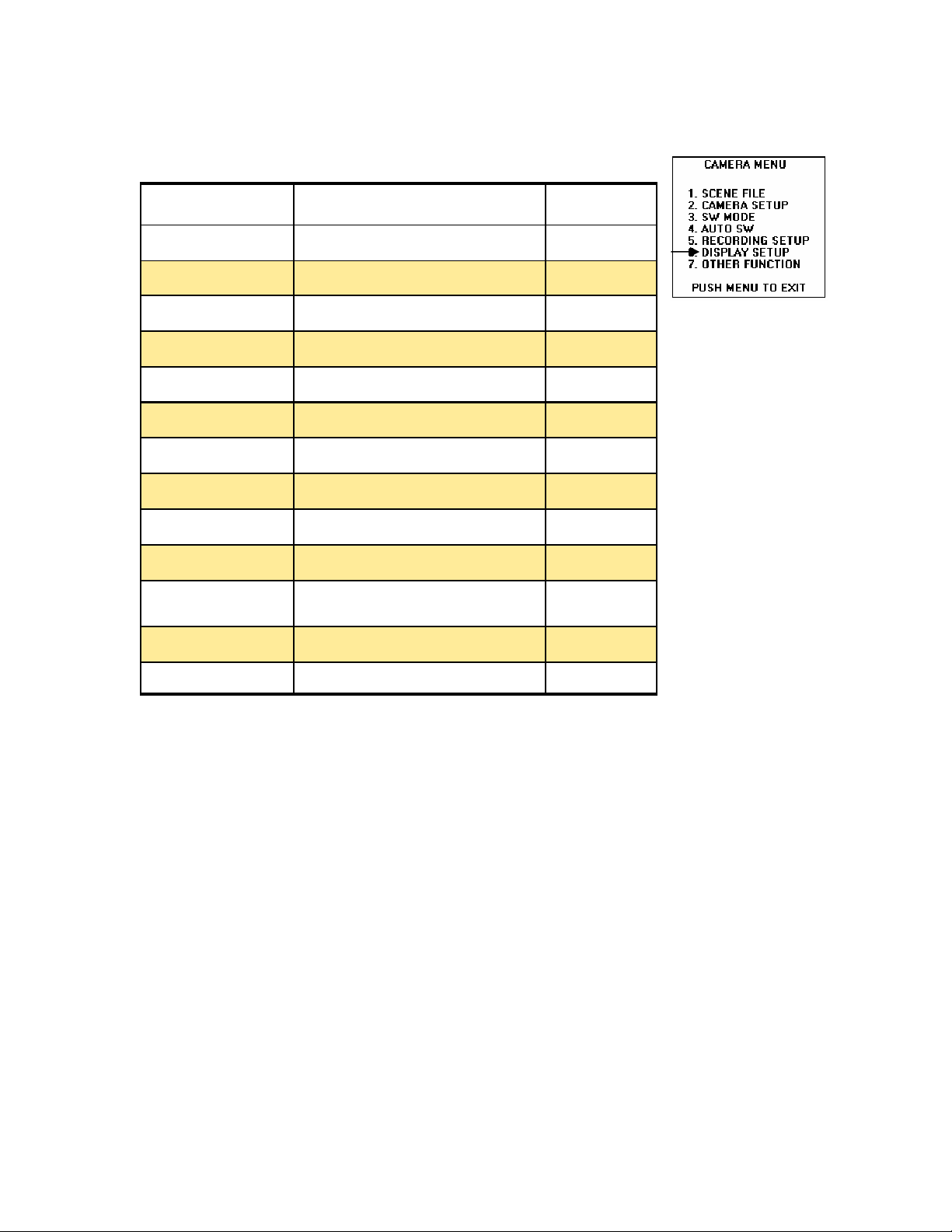
4.5 DISPLAY SETUP Screen
Item Settings Default
ZEBRA DETECT 1 80%, 85%, 90%, 95%, 100% 80%
ZEBRA DETECT 2 80%, 85%, 90%, 95%, 100% 100%
MARKER ON / OFF ON
VIDEO OUT OSD ON / OFF OFF
DATE / TIME OFF, TIME, DATE, TIME&DATE OFF
LEVEL METER ON / OFF ON
ZOOM-FOCUS ON / OFF ON
TAPE-BATTERY ON / OFF ON
OTHER DISPLAY OFF, PARTIAL, ALL PARITIAL
LCD BACKLIGHT HI / NORMAL NORMAL
LCD / EVF SET LCD BRIGHTNESS, LCD COLOR
LEVEL, EVF BRIGHTNESS
SELF SHOOT NORMAL / MIRROR MIRROR
EVF MODE ON / AUTO ON
YES
Zebra Detect 1
ures the peak value of white. A black and white striped diagonal pattern indicator, which is
superimposed on the picture and only appears in the LCD viewfinder, in portions of the
video image corresponding to the pre-set brightness level. This level is set between 80%
to 100% and will warn you when the video signal has reached the predetermined level.
There are two warning patterns used in the DVX-100, normally, Zebra Dectect1 is set to
80% and Zebra Detect 2 is set to 100%. Zebra Detect 1 Is indicated by diagonal strips
that start right top and Zebra Detect 2 is indicated by diagonal strips that start at the left
top. Remember, you must press the Zebra button to activate the Zebra function, each
time the ZEBRA button is pressed you will cycle from OFF to Zebra 1 to Zebra 2 to Marker
to OFF . Use these indications as a guide when you use the manual iris control in manual
mode to lower the brightness if whites are to high.
The Zebra Detect function is basically a built in light meter that meas-
Zebra Detect 2
ures the peak value of white. A black and white striped pattern only appears in the LCD
viewfinder or EVF, in portions of the video image corresponding to a pre-set brightness
level. This level is set here for 80% to 100%. Zebra Detect 2 is normally, set to 100%.
Remember you must press the Zebra button to activate the Zebra function.
The Zebra Detect function is basically a built in light meter that meas-
24
Page 25
Marker
This item allows the user to turn OFF or On a measurement value of the video
level. When on, at the bottom left of the viewfinder or LCD a measurement of the video
level from the center of these displays will be displayed. This is very useful to the user that
utilizes manual iris.
Video Out OSD
to the video output signal with the video image.
When turned ON all information displayed on the LCD or EVF is output
Date/Time
LCD or video output. You have four selections OFF, TIME will be displayed, DATE will be
displayed, and TIME & DATE will be displayed.
Note: If TIME, DATE or TIME & DATE is selected it will be displayed in the video output regardless of the VIDEO OUT OSD setting
This item is used to set the date and /or time that is displayed in the EVF,
Level Meter
turn it OFF.
ZoomyFocus
play or turn it OFF.
This item allows the user to display the audio level meter in the display or
This item allows the user to display the zoom and focus values in the dis-
TapeyBattery
ing battery charge in the display or turn it OFF.
This item allows the user to display the remaining tape amount and remain-
Other Display
formation when the MODE CHK button is pressed, some cases certain information is displayed already. This item has three choices OFF, PARTIAL and ALL. Default is PARTIAL
Counter Displa y Another setting Another setting Another Sett ing
Record Time Mode display (SP or LP) Displayed Dis played VCR, Not Cam era Not Displayed
Auto Iris control status display Displayed Dis played Not Di splayed
Shutter speed display Displayed Dis played Not Displ ayed
Audio level meter display Another setting Anot her setting Another setting
Audio sampling frequency display Displayed Dis played VCR, Not Cam era Not Displayed
Scene filename display Displayed Not Displayed Not Displa yed
Progressive display Displayed Not Di splayed Not Displayed
Zoom position dis play Another setting Anot her setting Another setting
AWB information display Displayed Displayed Not Displayed
Focus control inf ormation display Another setting Anot her setting Another sett ing
Iris display Displayed Displayed Not Di splayed
Gain display Displayed Not Di splayed Not Displayed
ND filter
Recommended ND f ilter display Displayed Displayed Not Di splayed
Date and time display Another setting Another se tting Another setting
Remaining batter y charge display Anot her setting Another setting Anot her setting
Remaining tape d isplay Another set ting Anot her setting Another sett ing
Camera shake compensation display Displayed Displayed Not Di splayed
Mic level automatic control display Displayed Not Displayed Not Displa yed
AUTO button operati on display Displayed Displayed Not Displa yed
The viewfinder and LCD monitor are capable of displaying 21 items of in-
Display Item ALL PARTIAL OFF
display
Displayed Not Di splayed Not Displayed
25
Page 26

LCD Backlight
NORMAL and HI are the two choices.
LCD/EVF Set
the LCD’s color level.
Allows the user to adjust the LCD’s monitor’s backlight slightly brighter,
Allows the user to adjust the viewfinder and LCD monitors brightness and
Self Shot:
person so he can monitor himself. When set to Mirror, the LCD monitor will be reversed at
the left and right for display during the face to face recording.
When doing a headshot or face-to-face shot you can turn the LCD toward the
EVF Mode
image will be shown at all times in the viewfinder. In the AUTO mode, when the LCD monitor is opened the video no longer appears in the viewfinder.
This item is used to select when the EVF will be on. When turned ON video
26
Page 27
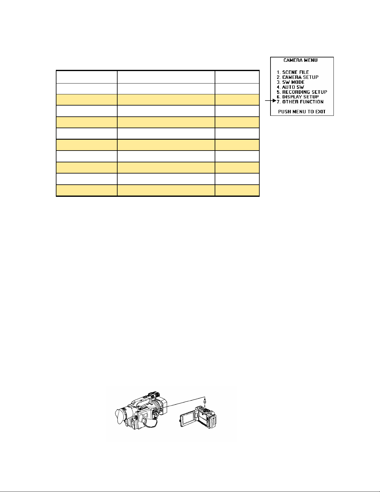
4.6 OTHER FUNCTIONS Screen
Item Settings Default
REMOTE VCR1, VCR2, OFF VCR1
DV CONTROL OFF, EXT, BOTH, CHAIN OFF
DV CMD SEL REC P / STOP REC P
REC LAMP OFF, FRONT, REAR, BOTH OFF
BEEP SOUND OFF / ON OFF
CLOCK SET SETS INTERNAL CALENDAR YES
TIME SHIFT +23h, +1h, OFF, -1h, 23h OFF
TAPE PROTECT POWER OFF / STBY POWER OFF
USER FILE LOAD, SAVE, INITIAL - - - -
HOUR METER VIDEO HEAD HOUR METER 00000H
Remote
3 settings, VCR1, VCR2 and OFF. When using two DVX-100’s this setting allows the two
camcorder to be control from one remote control, by selecting which camcorder you want to
control from the remote control. This item makes sure that only that one button (VCR1 or
VCR2) will operate this camcorder from the remote control. OFF the remote will not be able
to control the camcorder.
IEEE 1394
Serial Bus with a special protocol (set of rules). Part of that protocol has been used for high
speed digital video and audio transfer. Not only can you transfer video and audio, you can
transfer time code and control your VCR remotely. The cable used must not be longer then
4.5 meters.
DV Control:
connector located on the side, under a cover of the DVX-100. There are 4 selections:
OFF:
EXT: The START/STOP button will control the backup recording. In this mode only the
backup recorder will record the video and audio. The camcorder does not record.
BOTH: The video is recorded on both the camcorder and the backup unit.
CHAIN: used when additional record time is needed. Once the camcorder approaches the
end of its record time the backup unit will automatically start recording. Remember the back
up unit must be in the record standby mode to function.
This item is used to set the operations of the wireless remote control. There are
Or firewire as it is often called is an extremely high speed, high performance
This item selects the method for backup recording, using the DV (1394)
There is no control information supplied.
27
Page 28
DV CMD SEL:
This item sets the record function performed by the backup unit when
the START/STOP button on the camcorder is pressed. There are two choices
REC_P:
Allows switching between recording and pause.
STOP: Allows switching between recording and stop.
Note:
Used when backup unit does not have a pause mode
.
Rec Lamp:
off. The Front tally lamp selection allows the front tally lamp to function only. Rear selection allows the rear tally lamp to function only. Both allows both tally lamps to function.
Note: The tally lamps supply you with additional information:
8 blinks per second When a remote operation has been received.
8 blinks per second When Recording has started.
4 blinks per second When the video tape has come to the end.
4 blinks per second When a problem has arisen in the tape transport.
1 blink per second When there is little tape or battery charge remaining.
this item allows the user to control the tally lights, OFF turns both tally lights
Tally Lamp Operation
Beep sound
beep tone is sounded the audio signals from the output connectors are muted, and the
beep tone is output instead. When turned on, the beep tone have different meanings.
1 beep Sound When the power has been turned on.
1 beep Sound When you start to record.
2 beep Sounds When recording has been temporarily stopped.
10 beep Sounds When the cassette tape has not been inserted.
10 beep Sounds When the unit is in the pause mode.
10 beep Sounds When condensation has formed inside the Camcorder.
10 beep Sounds When a problem has occurred in the Camcorder.
Clock Set
der. The Year, Month, day, Hour and minutes. Which is held by an internal battery.
this item allows the user to turn the beep sound ON or OFF. When the
Beeps Operation
This item allows the user to set the internal time and calendar of the Camcor-
Time Shift
zones and countries without changing his original home time (CLOCK SETTING) setting.
This item effects both the viewfinder, LCD and the clock time recorded on the tape. This
adjustment is done in 1 hour increments, from +23 to –23 Hours and also a OFF position
which is the factory default.
When you travel, this item allows the user to set the time for different time
28
Page 29

Tape Protect
pause mode, it will be automatically be set to the tape protection mode. There are two
choices for this tape protection mode: POWEROFF which shuts off the power and STBY,
which only places the video heads in the stop mode.
When the unit has been left in standby for 5 minutes while in the record
User File
Load: which will load the last settings stored in the user file.
Save: this item allows the user to save any settings that have been changed.
Initial:
Note:
then ON in order to enable the settings.
This item has three settings:
this item allows the user to re-install the factory settings.
When the LOAD or INITIAL operation has been performed, turn the power OFF and
Hour Meter
ing, this is a 5 digit number, measured in 1 hour increments.
This item keeps a record of total hours that the video head has been rotat-
29
Page 30
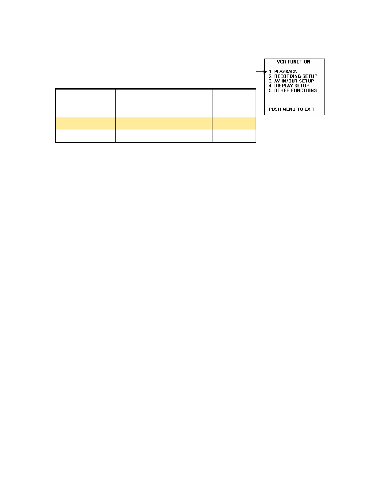
5. VCR
5.1 PLAYBACK FUNCTIONS Screen
Item Settings Default
END SEARCH BLANK / REC END BLANK
12 bit AUDIO ST1, ST2, MIX ST1
AUDIO OUT CH1-CH2, CH1, CH2 CH1-CH2
End Search
BLANK: In this mode the END SEARCH will look for any blank spaces on the videotape.
Rec End: In this mode the END SEACH will look for the video that was shot last.
Note: When placed in the Rec End function and a new videotape is used, this function will
not operate correctly. If the tape is blank the operation will stop at the end of the tape.
This item sets up the operation of the END SEARCH button when pressed.
12 bit Audio
audio Channels being used..
There are three selections:
ST1: CH1 signals are recorded on Channel 1 track
CH2 signals are recorded on Channel 2 track
ST2: CH1 signals are recorded on Channel 3 track
CH2 signals are recorded on Channel 4 track
MIX:
CH2 signals are recorded on Channel 2 and Channel 4 tracks
NOTE: If the audio has been recorded in the 16 bit mode, there will be no Channel 3 or
Channel 4. In this mode there will only be:
CH1 signals are recorded on Channel 1 track
CH1 signals are recorded on Channel 1 and Channel 3 tracks
CH2 signals are recorded on Channel 2 track
When making a recording in the 12 bit audio mode, this item will choose the
Audio Out
videotape is played back.
CH1 yCH2 Channel 1 Connector has Channel 1 audio signals
Channel 2 Connector has Channel 2 audio signals
CH1 Channel 1 Connector has Channel 1 audio signals
Channel 2 Connector has Channel 1 audio signals
CH2 Channel 1 Connector has Channel 2 audio signals
Channel 2 Connector has Channel 2 audio signals
used to set the audio signals that are sent to the RCA connectors when the
30
Page 31
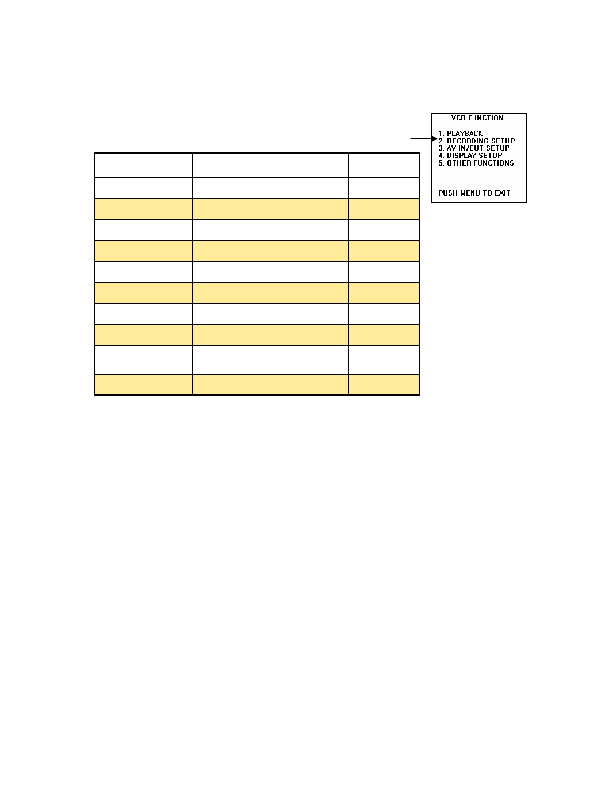
5.2 RECORDING SETUP Screen
(Same Menu used for the Camera, some functions not used)
REC SPEED SP / LP SP
Item Settings Default
AUDIO REC 12bit / 16 bit 16bit
1394 TC REGEN OFF / ON ON
TC MODE DF / NDF -50dB
TCG FREE RUN / REC RUN -50dB
FIRST REC TC REGEN / PRESET DF
TC PRESET INPUT START OF TIME CODE - - - -
1394 UB REGEN OFF / ON OFF
UB MODE USER, TIME, DATE, TCG, FRM
RATE
USER
UB PRESET USER bit - - - -
Rec Speed
for long play
allows the user to select the recording time, either SP for standard play or LP
Audio Rec
(16 bit/48kHz)
1394 TC Regen
connector.
OFF:
item and the First REC TC item.
ON: The signal recorded will use the time code from signal being recorded from the DV
connector.
Note: When ON is used, it will take precedence over TC MODE item, TCG item and the
First REC TC item. If no Time code is supplied to the DV connector, TC MODE item, TCG
item and the First REC TC item will be used.
The signal recorded will use the time code set up using the TC MODE item, TCG
used for selecting the method of recording audio, 12 bit (12bit/32kHz) or 16 bit
This item is used to select the time code that will recorded from the DV
TC Mode
explained earlier this item corrects for timing differences.
Note: When the progressive mode, 24P or 24P ADV is used, the non drop frame mode is
set regardless of the setting. See more information about Time Code on page 21
this item selects DF (Drop Frame) or NDF (Non-drop Frame) modes and as
31
Page 32

TCG
RUN mode.
First Rec TC
recording is started.
PRESET: here the time code is recorded using the value set in the TC PRESET item serving as the initial value.
REGEN: in this mode the time code is regenerated from the time code on the video tape
TC PRESET
TC is selected.
Note: When the 24P or 24P ADV modes are used you must set the frame value to 0 or a
multiple of 5. If you use any other value the time code recorded will shift.
1394 UB Regen
used.
OFF: The user’s bit selected in the UB Mode item is used for the recording.
ON:
Note:
The user’s bit is not recorded if the signal does not contain the user’s bit information
And when there is no signal supplied to the DV connector the UB MODE item is used.
This item selects FREE RUN OR REC RUN, as explain its best to leave in the REC
This item allow the user to select the time code that will be used when
This item is used to set the initial value used, when the PRESET in First Rec
This item selects the user’s bit to be recorded when the DV connector is
The user’s bit of the signals input of the DV connector is used for recording.
When set to ON, this setting takes precedence over the UB MODE item setting.
UB Mode
bits. The user may select one of 5 items:
User:
Time:
Date:
TCG:
FRM Rate:
digital number, which contains the following information. The user’s bit value verification
information, the frame sequence number, the frame rate information and the recording control information.
This selection allows the user to set up the information to be recorded as user
the user’s information, which is selected in the UB PRESET item.
The time that the recording was made.
The date that the recording was made.
The time code generator’s value is recorded.
The frame rate information for frame conversion is recorded. This is a 8 bit
UB Preset
the UB Mode item setting. The user’s bit has 8 bits, which can be set 0 to 9, A to F
This item is used for setting the user’s bit, make sure that USER is selected in
32
Page 33
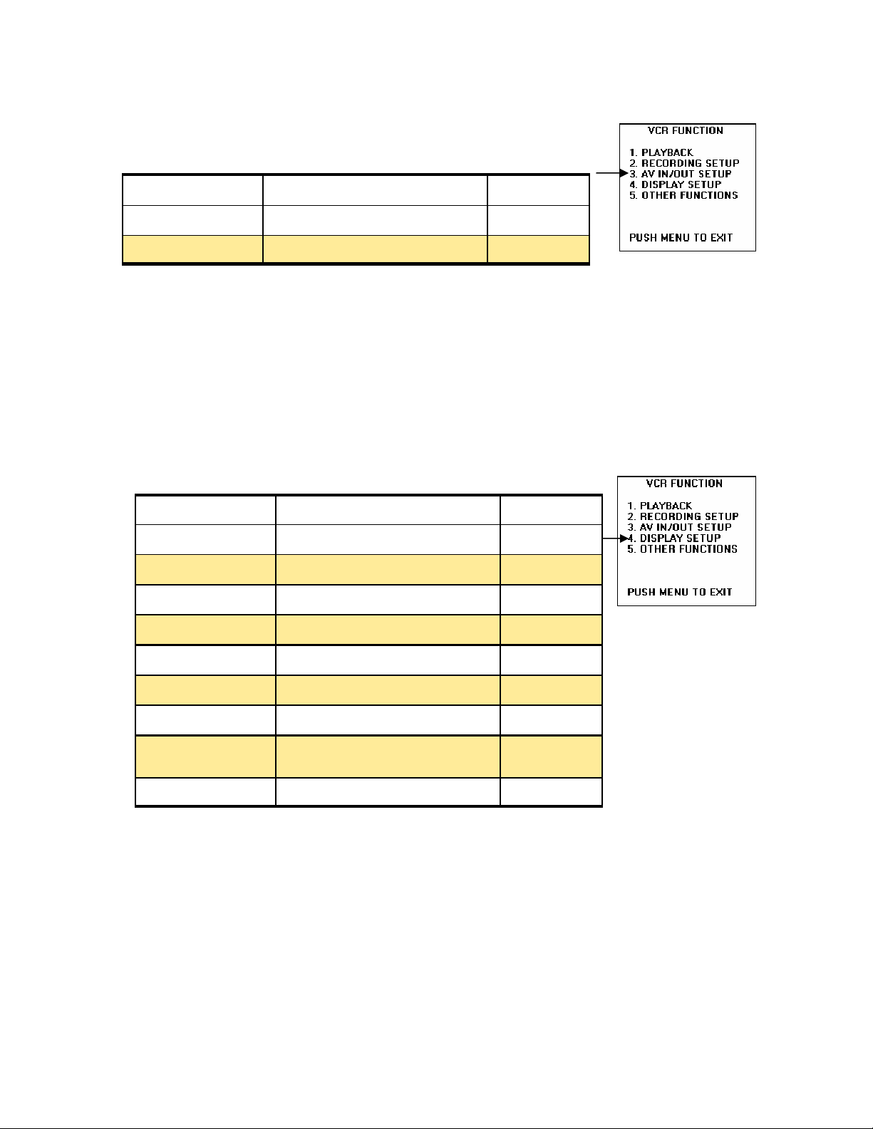
5.3 AV IN / OUT SETUP Screen
Item Settings Default
A DUB INPUT MIC / A_IN MIC
DV OUT OFF / ON OFF
A Dub Input
dub is performed.
: Selects the audio from the internal microphone or the external inputs to be recorded
MIC
from the INPUT 1 and INPUT 2 XLR jacks. This is chosen with the CH1 SELECT and the
CH2 SELECT switches on the side of the DVX-100.
A_IN The audio connected to the RCA AUDIO IN connectors is recorded.
DV OUT
This selection allows you to pick the audio source to be used when an audio
This item turns ON or OFF the DV connector. .
5.4 DISPLAY SETUP Screen
Item Settings Default
DATE / TIME OFF, TIME, DATE, TIME&DATE OFF
LEVEL METER OFF / ON ON
TAPE BATTERY OFF / ON ON
OTHER DISPLAY OFF, PARTIAL, ALL PARTIAL
VIDEO OUT OSD OFF / ON OFF
CAMERA DATA OFF / ON ON
LCD BACKLIGHT HI, NORMAL NORMAL
LCD / EVF SET LCD BRIGHT, COLOR LEVEL
EVF BRIGHTNESS
EVF MODE ON / AUTO ON
YES
Date/time
or video output. You have four selections OFF, TIME will be displayed, DATE will be displayed, and TIME & DATE will be displayed.
Note:
gardless of the VIDEO OUT OSD setting
This item is used to set the date and /or time that is displayed in the EVR, LCD
If TIME, DATE or TIME & DATE is selected it will be displayed in the video output re-
33
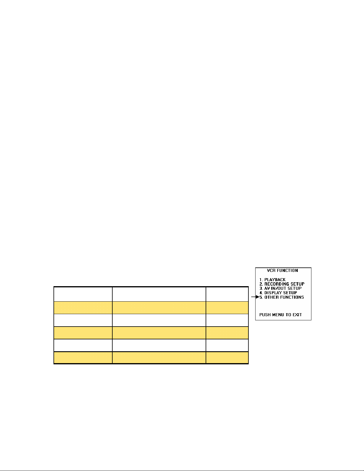
Page 34
Level Meter
turn it OFF.
This item allows the user to display the audio level meter in the display or
Tape Battery
maining battery charge in the display or turn it OFF.
This item allows the user to display the remaining tape amount and re-
Other Display
information when the MODE CHK button is pressed, some cases certain information is
displayed already. This item has three choices OFF, PARTIAL and ALL. Default is PARTIAL, See page 24 for the list of displayed items.
The viewfinder and LCD monitor are capable of displaying 21 items of
Video Out OSD
put to the video output signal with the video image.
Camera Data
camera shake correction, iris value and gain value when the unit is in VCR mode and
playing back. OFF turns this feature OFF.
LCD Backlight
brighter, NORMAL and HI are the two choices.
LCD/EVF Set
and the LCD’s color level.
When turned ON all information displayed on the LCD or EVR is out-
This item allows the user to turn ON the camera information, such as
Allows the user to adjust the LCD’s monitor’s backlight slightly
Allows the user to adjust the viewfinder and LCD monitors brightness
EVF Mode
age will be shown at all times in the viewfinder. In the AUTO mode, when the LCD monitor is opened the video no longer appears in the viewfinder.
This item is used to select where the video will be displayed. ON video im-
5.5 OTHER FUNCTIONS Screen
Item Settings Default
REMOTE VCR1, VCR2, OFF VCR1
CLOCK SET SETS INTERNAL CALENDAR - - - -
TIME SHIFT +23h—+1h, OFF, 1h—23h OFF
USER FILE LOAD, SAVE, INITIAL - - - -
HOUR METER VIDEO HEAD HOUR METER 00000H
Remote
are 3 settings, VCR1, VCR2 and OFF. When using two DVX-100’s this setting allows the
two camcorder to be control from on remote control, by selecting what camcorder you
want to control on the remote control. This item makes sure that only that one button
(VCR1 or VCR2) will operate this camcorder from the remote control. OFF setting the
remote will not be able to control the camcorder.
This item is used to set the operations of the wireless remote control. There
34
Page 35

Clock Set
der. The Year, Month, day, Hour and minutes.
This item allows the user to set the internal time and calendar of the Camcor-
Time Shift
zones and countries without changing his original home time (CLOCK SETTING) setting.
This item effects both the viewfinder, LCD and the clock time recorded on the tape. This
adjustment is done in 1 hour increments, from +23 to –23 Hours and also a OFF position
which is the factory default.
User File
Load:
Save:
Initial:
Note:
then ON in order to enable the settings.
which will store the last settings in the user file.
this item allows the user to save any settings that have been changed.
When the LOAD or INITIAL operation has been performed, turn the power OFF and
When you travel, this item allows the user to set the time for different time
This item has three settings:
this item allows the user to re-install the factory settings.
Hour Meter
ing, this is a 5 digit number, measured in 1 hour increments.
This item keeps a record of total hours that the video head has been rotat-
35
Page 36

6. Video Glossary
24 frames per second progressive, a standard for digital video
24p
4:1:1 A sampling frequency ratio used in digitizing a video picture’s luminance and color
difference components (Y, R-Y, and B-Y). In this ratio the luminance is sampled at 13.5
MHz and R-Y , B-Y are each sampled at 3.37 MHz.
4:2:2 A sampling frequency ratio used in digitizing a video picture’s luminance and color
difference components (Y, R-Y, and B-Y). In this ratio the luminance is sampled at 13.5
MHz and R-Y, B-Y are each sampled at 6.75 MHz. This method of digitizing provides a
wider chrominance bandwidth relative to luminance.
A
Automatic Level Control, a circuit that is used to maintain a constant signal level.
ALC
Amplifier A component that increases the level of an audio signal from line level to speaker
level.
Analog A signal that can be continuously varied in amplitude and frequency.
Analog Components Video signals in which a continuously variable voltage or current
represents the value of a pixel.
Aspect Ratio
on a screen. The old standard NTSC aspect ratio was 1.33 to 1 or 4 to 3, but now with at
advent High Definition technology 16 by 9 is common.
B
Back Light The main function of the backlight is to separate the individual subjects from the
background and give them depth and dimension.
Back Porch The period of time during horizontal blanking that follows the horizontal sync
pulse and continues to the beginning of active video.
Backlit Refers to the illumination used to light a projectors control panel or the buttons of a
remote control, so it can be used in the dark.
Black Level
black areas of the picture.
Blanking or Composite Blanking
tal and vertical components and is at its negative level whenever video is to be blanked or
turned off.
Blanking Level Also known as pedestal, it is the level of a video signal, which separates
the range that contains the picture information from the range that contains the synchronizing information. The level of the front and back porches. Is Zero IEEE units.
C
Charge Coupled Device
CCD
CCIR -
which now falls under the control of the ITU-R.
CCIR 601 (ITU-R 601) - This standard defines the encoding parameters of digital television.
Charged Coupled Device Is a sensor used in scanners, camcorders, digital cameras, etc.,
to capture an image. CCDs work by converting light into electrical energy.
Chroma The color information contained in a video signal, consisting of hue (phase angle)
and saturation (amplitude) of the color sub carrier. Also, known as Chrominance.
Chrominance
brightness or luminance of the signal, e.g. black, gray and white, have no chrominance, but
any colored signal has both chrominance and luminance. U,V: Cr, Cb: I,Q: (R-Y, B-Y) represent the chrominance information of a signal.
Comite Consultatif International Radiocommunications, the French standards body
The ratio of the width to height of a video screen or film when it is projected
The level of the video signal that corresponds to the maximum limits of the
Related to composite sync, this signal has both horizon-
The color part of a signal, relating to the hue and saturation but not to the
36
Page 37

Coated Optics Is lens with a special coating to minimize the amount of light reflected back
to the lamp, and the amount of ambient light that mingles with the focused light leaving the
lens.
Codec
Color Bars
Coder Decoder, a device used to encode a signal and decode it.
A test signal that should be recorded at the beginning of every videotape. The
color bars test signal provides the necessary elements of a video signal that are added during the initial set up of a tape machine.
Color Burst A few (8 to 10) cycles of 3.58MHz color sub carrier, which occur during the
back porch interval. Color burst amplitude is 40 IEEE units and phase is 180 degrees. The
color oscillator of a color television receiver is phase locked to the color burst.
Color Difference Signal The calculation of the chroma signal (R-Y, B-Y and G).
Color Phase
The correct timing relationship within a color display - color is considered to
be in-phase when the hue is reproduced correctly.
Color Sub carrier
The 3.58MHz signal which carries color information. This signal is superimposed on the luminance level. Amplitude of the color sub carrier represents saturation
and phase angle represents hue.
Color Temperature A measurement of overall color of a source of light, measured in degrees Kelvin (K). The higher the Kelvin reading the more blue the light, the lower the Kelvin
Temperature the redder the light. Normally, video uses lights that are 3200 Degrees Kelvin.
Component The normal interpretation of a component video signal is one in which the luminance and chrominance are sent as separate components, e.g. Analog components in MII
and Betacam VCRs, digital components UCRCB in CCIR re 601. RGB is, however, also a
component signal. Component video signals retain maximum bandwidth, unlike composite
systems.
Composite A composite video signal is one in which the luminance and chrominance information have been combined using one of the coding standards: NTSC, PAL, SECAM, etc.
Composite Sync A signal consisting of horizontal sync pulses, vertical sync pulses, and
equalizing pulses only, with a no signal reference level.
Composite Video A mixed signal comprised of the luminance (black and white), chrominance (color), blanking pulses, sync pulses and color burst.
Compression
A process used to store digital information in a smaller block of space than it
would normally take
Compression Ratio
This is the ratio of data in the original video picture signal to the
amount of data after compression.
Contrast The range of light and dark values in a picture or the ratio between the maximum
and the minimum brightness values. Low contrast is shown mainly as shades of gray, while
high contrast is shown as blacks and whites with very little gray. It is also a TV monitor adjustment, which increases or decreases the level of contrast of a televised picture.
Contrast Ratio
A method of measuring the dynamic range of an image. A large contrast
ratio indicates that the projector works well despite extraneous light.
D
DATA
Digital information stored or used by a computer
dB Decibel
dBm A measurement of sound, measurement made across 600 ohms.
DCT - Discrete Cosine Transformer is widely used to compress video; here 8x8 picture ele-
ments are converted to 8x8 frequency elements. This way the higher frequency numbers
can be minimized and compression made simpler.
Digital Video
DV
37
Page 38

DVCPRO - New digital format
Decibel (dB) One decibel is one tenth of a Bel and is used to measure audio and video sig-
nals expressed by the ratio of two amounts of electric. It is also used to measure power differences in voltage, current, watts and sound pressure
Depth of Field
The front to back zone in a field of view, which is in focus in the televised
.
scene. With a greater depth of field, more of the scene, near to far, is in focus.
Detail Resolution or clarity of the picture.
Drop Frame A type of time code that can be used as a real time reference.
E
Error Concealment Use to conceal errors in digital recorded.
F
Used in editing to gradually increase or decrease the video signal from black. Fading
Fade
in is from black to full strength and fade out is from full strength to black.
One half of a scanned image. A field can be referred to as an odd field or an even
Field
field. Each field is made up of 262 1/2 lines. There are two fields per frame and 60 fields per
second.
Two fields make up a complete television picture (frame). The lines of Field 1 are vertically
interlaced with Field 2 for 525 lines of resolution.
Flying Erase Head A special video erase head that allow for cleaner edits.
F Number In lenses with adjustable irises, the maximum iris opening is expressed as a ra-
tio, (focal length of the lens) (maximum diameter of aperture).
Focal Length
The distance from the center of the lens to a plane at which point a sharp image of an object viewed at an infinite distance from the camera is produced. The focal
length determines the size of the image and the angle of the field of view seen by the camera through the lens. That is the distance from the center of lens to the pickup device.
Foot Candle The amount of light reflected by a white surface one foot away from a lit candle. The metric equivalent is the lux.
Foot Lambert One lumen or one foot candle of light over a one square foot surface.
Format In recording of video, C, U-Matic, Betacam, M, Betacam SP, M-II, D1 D2, D3, D5,
DV, DVCPRO, Beta, VHS, Hi8, 8mm and S-VHS are all current formats.
Frame
The combination of an odd and even field of the video signal. In each frame of video
there are 525 lines of information in the NTSC system. There are thirty frames in a second.
(625 lines, 1/25 sec. in Europe and many other countries).
Frame Rate The amount of frames per second that has been set up for a particular television system. Black and white television uses a thirty frame per second rate, while color television uses 29.97 frames per second rate.
Frequency Response The frequency range that both audio or video systems can reproduce a signal within a stated amplitude range.
Front Porch
That period of time during horizontal blanking that starts from the end of the
scanned video image and goes to the horizontal sync pulse.
G
The amplification of a unit.
Gain
Gray Scale A series of tones, which range from true black to true white, it is usually ex-
pressed in 10 steps.
H
HDTV High Definition Television
Hz Hertz
The parts of a tape machine that play back or record signals on the tape.
Head
38
Page 39

Herz A measurement of cycles per second.
High Definition Television (HDTV) Refers to the new television format which has an elon-
gated shape and a significantly higher resolution than current television.
Horizontal Blanking
The period of time which the electron beam is blanked off while it
moves back to the left side of the picture to get ready to start scanning the next line.
Horizontal Frequency
The inverse of the time it takes for a monitor to scan from the beginning of one line to the beginning of the next line; typically stated in kilohertz.
Horizontal Resolution Smallest increment of a television picture that can be discerned in
the horizontal plane. This increment is dependent upon the video bandwidth and is measured in frequency.
Hue The degrees of the vector on the vectorscope which represents a color.
(A) Distinction between colors. Red, blue, green, yellow, etc. are hues. White, black, and
gray are not considered hues. (B) The dimension of color that is referred to a scale of perceptions ranging from red through yellow, green, blue, black to red.
I
IC - Integrated Circuit
IRE Institute of Radio Engineers
ITU International Telecommunications Union
Impedance A measure of how much something resists (impedes) the flow of electricity.
Insert Edit A type of edit where new video or audio is recorded onto existing materials. The
existing materials control track remains unchanged.
Interlace Scanning
The process of combining two fields of video information One field has
the odd lines of the image scanned and the other field has the even lines of the image
scanned. The two fields, odd and even, are interlaced together to form one complete image,
or frame of video.
IRE Units of measurement dividing the area between the bottom of sync and white level into
140 equal units. 140 IRE units are equal to 1 volt peak-to-peak.
Iris The amount of light transmitted through a lens is controlled by an adjustable diaphragm,
or iris, located in the lens barrel. The opening is referred to as the aperture, and the size of
the aperture is controlled by rotating the aperture control ring on the lens barrel. The
graduations on the lens barrel are expressed in terms of the focal length f of the lens divided by the diameter of the aperture at that setting. This ratio is called the f-number.
J
JPEG Joint Photographic Experts Group is a subcommittee of the International Standards
Organization (ISO), which defines standards for digital photographic compression and decompression.
Jitter Small and rapid variations in a waveform due to mechanical disturbances, changes in
the characteristics of components, supply voltages, imperfect synchronizing signals, circuits, etc.
K
Or Kilo is the term used in computers to define 1,024 bytes.
K -
Kilohertz
KHz
Kelvin An International standard unit of color temperature. This standard is measured in
digress.
Kilohertz (KHz) A 1000 Hertz
L
LCD Liquid Crystal Display -- a display that works by controlling the opacity of LCD "glass"
by varying the electrical signal. Each individual pixel acts as a shutter, to modulate light
39
Page 40

being passed through.
Letterbox Format used to fit wide screen movies (1.85:1 and 2.35:1, for example) on the
average, 1.33:1 TV screen. The image is shrunk to fit the screen, leaving blank space on
the top and bottom.
Line Frequency
The rate or number of video lines that are being read or scanned by the
electron beam per interval. There are 262 1/2 lines scanned per field, 525 lines scanned
per frame and 15,750 lines of video information scanned every second.
Liquid Crystal A liquid in which the molecules are arranged in a regular pattern.
LTC (Longitudinal Time Code) This is another expression for the SMPTE time code sig-
nal recorded onto the third audio track of a videocassette tape.
Luminance refers to the amount of visually effective light emitted by a light source. Typically expressed in nits, foot lamberts (fL) or candelas per square meter (cd/m2). One fL =
3.43 cd/m2 or 3.42626 nits, One cd/m2 = 0.292fL or 1 nit
A unit of measuring the e intensity of light. (1 FC=10.76 lux).
Lux
M
MHz Short for megahertz, which is 1 million Hz.
MPEG Motion Pictures Expert Group
Megabyte One million bytes of data.
Memory A storage place for computer data.
Microphone A piece of equipment that will convert sound into electrical signals for re-
cording and use by audio equipment, such as sound amplifiers.
N
NTSC
National Television Standard Committee (NTSC
National Television Systems Committee
) This organization formulated the
NTSC system, 525 lines 60 field; usually taken to mean the NTSC color television system
itself, or its interconnect standards.
Non-Drop Frame A type of time code that runs at thirty frames a second and does not
allow for the slower color frame rate of television.
NTSC Color Bars A pattern generated by the NTSC Generator, consisting of eight equal
width color bars. Colors are white (75%), black (7.5% set-up level), 75% saturated pure
colors red, green, and blue, and 75% saturated hues of yellow, cyan, and magenta.
(Mixtures of two colors in 1:1 ratio without third color).
O
One Volt "Peak to Peak" - A reference to the measurement of a video signal which
should go from -40 IRE units for sync up to 100 IRE units for the luminance level. The distance from -40 to 100 (140 IRE units) is referred to as 1 volt peak to peak.
P
PCM Pulse Code Modulation
Peak White
Pedestal
Phone Plug
The white portion of the video signal.
The level of the video signal representing black, normally set at 7.5 IRE units.
This type of plug is mostly used on a microphone or pair of headsets. There
are basically two types stereo and mono.
Phono Plug Known as a RCA plug it is used with audio amplifiers.
Pixel Picture Element or Pix Element; related to a particular image address in digital sys-
tems or to the smallest reproducible element in analog systems.
Pixel Depth The number of bits used to address a pixel. Also called color depth, the bit
depth determines the number of colors that can be displayed at one time.
Power Zoom
A zoom lens that has a motor, which allows you to zoom in and out from the
40
Page 41

projector's control or remote control.
Primary Colors Colors usually three, which are combined to produce the full range of
other colors within the limits of a system. All non-primary colors are mixtures of two or
more of the primary colors. In television, the primary colors are specific sets of red, green,
and blue.
Progressive scan
Computer images are all progressively scanned. Now, we are using
this type of scanning for HDTV. Instead of having two fields and interlacing them together
to form a frame or an image, we show each frame of a video image completely, from top
to bottom, not interlaced.
Q
R
RCA jacks
RCA connections for RCA cables, carrying line-level audio signals and some-
times video signals.
Resolution
(A) A measure of the ability of a camera or television system to reproduce detail. That is the number of picture elements that can be reproduced with good definition. It
is a factor of the pickup device or the TV CRT characteristics and the signal bandwidth.
(B) Generally called horizontal
resolution. It can be evaluated by establishing the limit to which lines can be distinguished
on a test pattern. A larger resolution value means a broader frequency band of the video
signal. (C) A measure of the greatest amount of detail that can be seen, or resolved, in an
image. Often incorrectly expresses as a number of pixels on a given line. More correct is
the bandwidth.
RGB, RGB Format, RGB System
Red, Green, and Blue: The basic parallel component
set in which a signal is used for each primary color; or the related equipment or interconnect formats or standards. The same signals may also be call "GBR" as a reminder of the
mechanical sequence of connections in the SMPTE interconnect standard.
S
SW - Switch
S-VIDEO - The generic name for Y/C video, applied to S-VHS or Beta ED
Sampling
Saturation
A process in which an analog signal is converted into a series of digital values.
The quantity of chrominance information present, (for example, the difference
between red and pink is that red is more saturated than pink.)
Set Up
- A reference to the black level in the videotape signal, also known as pedestal.
Signal A variation in an electrical current that represents either an audio signal or a video
signal.
Signal-to-Noise Ratio (S/N) - An S/N ratio can be given for the luminance signal, chrominance signal; and audio signal. The S/N ratio is the ratio of noise to actual total signal, and
it shows how much higher the signal level is than the level of noise. It is expressed in decibels (dB), and the bigger the value is, the more crisp and clear the picture and sound will
be during playback.
Sub carrier
Also SC, 3.58, 3.58CW - This is the basic signal in all NTSC sync signals. It is
a continuous sine wave, usually generated and distributed at 2 volts in amplitude, and has
a frequency of 3.579545MHz. Sub carrier is usually divided down from a primary crystal
running at 4.318180MHz, and that divided by 4 is 3.579545. All other synchronizing signals are directly divided down from
sub carrier.
Sync Also Composite Sync - This signal is derived from a composite or combination of
horizontal and vertical drives, with some slightly narrowed and delayed pulses as well as
the addition of equalizing pulses. It is one of the more popular signals used in video
41
Page 42

systems today, and when used, is usually accompanied by sub carrier.
T
A medium capable of storing an electronic signal and consisting of backing, binder,
Tape
and iron oxide coating. The orientation of the iron oxide determines whether the tape can
be used for helical scan video recording.
Tape Guides
Guides that are replaced on a VTR that make sure the tape stays within the
correct path from the supply reel to the take up reel.
Test Signals Signals such as color bars, stair step, multiburst and cross hatch that are
used in the setting up and checking out of a VTR.
Time Code - A labeling system that is used to identify a specific frame of videotape. It can
be an audio signal recorded on Track 2 or a video signal that is recorded in the vertical
interval of a tape.
Time Code Editing
By recording a sequential time code along with the video and audio
material, you can obtain a more precise reference for editing. Each frame has its own
number or code, which tells the time in hours, minutes, and seconds, and includes a frame
number. The world standard code is called SMPTE (Society of Motion Picture and Television Engineers) and has also been adopted by the IEC (International Elecrotechnical Commission). Time codes permit very fast and accurate editing. Automatic editing is possible
under computer control.
Tripod A three-legged stand on top of which a camera is mounted
Tripod Head
The top portion of a tripod where its legs meet and the camera is mounted;
friction or fluid-head tripod designs are available.
U
Underwriters Laboratory.
UL Underwriters Laboratory (UL) A non-profit safety organization in the U.S. that inspects
and certifies the products sold in the U.S. for their safety standards.
V
VCR - Video Cassette Recorder.
VITC - Vertical Interval Time code
Video tape recorder
VTR
Vertical Interval
That portion of the video signal that includes the vertical blanking, the
vertical sync pulses and the pre and post-equalizing pulses. It is also the area where other
information that is carried with the television signal, such as captioning and satellite instructions, are inserted.
Vertical Scan The action of the electron beam sweeping across the entire face of the display.
Video Level A measurement of the video level or luminance level of the video signal. The
video level should not exceed 100 IRE units.
W
Is a unit of measurement of power.
Watt
WFM (WAVEFORM MONITOR)
- A type of oscilloscope that is used to display the lumi-
nance, chrominance and timing diagrams of the video signal.
White Balance A method of setting a camera for the correct color temperature.
X
Y
Y Signal The luminance portion of the color signal.
Z
Zoom Lens
A lens with a variable focal length. Which allows you to adjust the size of the
image on a screen by adjusting the zoom lens.
42
 Loading...