

A-PDF Merger DEMO : Purchase from www.A-PDF.com to remove the watermark

INDEX
1. Machinery Specifications
2. Safety Procedures
3. Maintenance
4. Operating Instructions
5. Tyre Pressures, Bolt Torque’s
6. Anti-Splash Attachments
7. Front Drive Assembly Illustration
8. Front Drive Assembly List
9. Auger Assembly Illustration
10. Auger Assembly List
11. Feed Out Rotor Assembly Illustration
12. Feed Out Rotor Assembly List
13. Cam Arm & Moving Wall Assembly Illustration
14. Cam Arm & Moving Wall Assembly List
15. Rotor Cover & Tray Assembly Illustration
16. Rotor Cover & Tray Assembly List
17. Rear Plate & Bearing Assembly Illustration
18. Rear Plate & Bearing Assembly List
19. Door, Door Cylinder & Door Track Assembly Illustration
20. Door, Door Cylinder & Door Track Assembly List
21. Door Cylinder Assembly Illustration
22. Door Cylinder Assembly List
23. Tray Tensioned Lever Assembly Illustration
24. Tray Tensioned Lever Assembly List
25. Door Indicator Assembly Illustration
26. Door Indicator Assembly List
27. Hydraulics Layout Illustration
28. Hydraulics List
29. 1300, 1600 & 2000 Lights Illustration
30. 1300,1600 & 2000 Lights List
31. 3000 Lights Illustration
32. 3000 Lights List
33. 1300/1600 Axle Assembly Illustration
34. 1300/1600 Axle Assembly List
35. 2000 Axle Assembly Illustration
36. 2000 Axle Assembly List
37. PTO Drive Shaft Illustration
For Harry West (Prees) Ltd. use only.
3000 XX570002 onwards
2000 XX20236 onwards
1600 XX161252 onwards
1300 XX13518 onwards

SPECIFICATION – METRIC
MODEL
1300
Tyre Size 18.4 x 26
x 12 ply
Tyre Pressure – bars 2.6 2.3 2.6 2.2
Overall Height – metres 2.12 2.22 2.35 2.85
Overall Width 2.42 2.64 2.64 2.9
Overall Length 4.70 5.49 5.66 6.34
Level Volume – Litres 5910 7274 9092 13638
Unladen Weight – tonnes 3.04 3.40 3.84 4.96
Gross Weight – tonnes 8.933 10.653 12.905 18.558
P.T.O. Speed – r.p.m 540 540 540 540
Min. Tractor – h.p. 70 80 80 110
Axle Beam – mm.sq. 90 90 100 100
Auger Dia – metres 0.74 0.74 0.74 0.74
Auger Speed – r.p.m 10.8 10.8 11.2 11.2
Feed Out Rota Dia. – metres 0.63 0.63 0.63 0.614
Feed Out Rotor – r.p.m 508 508 508 508
Hydraulic Pressure 170 bars max
MODEL
1600
23.1 x 26
x 14 ply
MODEL
2000
23.1 x 26
x 16 ply
MODEL
3000
650/65-30.5
x 16 ply
SPECIFICATION – IMPERIAL
MODEL
1300
Tyre Size 18.4 x 26
x 12 ply
Tyre Pressure – p.s.i 38 34 38 32
Overall height 6'11" 7'3" 7'9" 9’4”
Overall width 7'11" 8'8" 8'8" 9’6”
Overall Length 15'5" 18'0" 18'7" 20’9”
Level Volume – Gallons 1300 1600 2000 3000
P.T.O. Speed – r.p.m 540 540 540 540
Min. Tractor – kw 52 60 67 82
Axle Beam – sq. in. 3-5" 3-5" 4" 4”
Auger Dia – ins 29" 29" 29" 29”
Auger Speed – r.p.m. 10.8 10.8 11.2 11.2
Feed Out Rotor Dia – ins 2’10” 2’10” 2’10” 2’
Feed Out Rotor – r.p.m 508 508 508 508
Hydraulic Pressure 2500 lb/in²
MODEL
1600
23.1 x 26
x 14 ply
MODEL
2000
23.1 x 26
x 16 ply
MODEL
3000
650/65-30.5
x 16 ply
1

SAFE STOP PROCEDURE
• Make sure handbrake is fully applied.
• Make sure all controls and equipment is left safe.
• Stop the engine.
• Remove the key.
Always use SAFE STOP:
• Before leaving your seat; or
• When anyone else approaches; or
• When anyone else is working on the machine.
You need to take extra precautions when safe stop is not possible.
SAFETY
1. Keep all personnel clear of machine when spreading or manoeuvring
2. Do not permit anyone to ride on machine.
3. Never enter machine to clear blockages unless the SAFE STOP PROCEDURE has been followed and P.T.O. drive
shaft disconnected at the tractor end before carrying out adjustments, inspections or service.
4. Always disconnect the P.T.O drive shaft at the tractor end before carrying out adjustments, inspections or service.
5. In use keep all guards in place, they are for your protection and ensure that the P.T.O shaft guard chains are secure.
6. P.T.O Drive Shaft – check there is a minimum overlap of 150mm of the lemon section tubes and that these tubes do
not bottom on full lock. Should the tubes need shortening cut equal amounts from each tube and the plastic guard
tubes.
7. Check tractor is large enough to control the machine in all conditions, do not overload the spreader.
8. Check hydraulic circuits functioning, especially the brakes. Hoses need to be checked periodically for excessive
cracking or damage that may compromise their functionality. Always ensure SAFE STOP PROCEDURE is in place.
9. Foreign bodies in manure – the machine can throw stones or other objects a great distance. Ensure the machine is kept
well clear of people, roads and buildings.
10. Rotor tips and channels – check for wear and damage. Replace as necessary.
11. Disengage P.T.O clutch when turning sharp corners.
12. Operation of lights must be checked periodically.
13. The driver must not exceed 20mph while towing this machine.
14. Care must be taken when traversing across any land with an incline of greater than 5 degrees, as there is a danger of
the vehicle overturning.
15. Tyre pressure must be maintained for safe use of machinery.
2

MAINTENANCE
• P.T.O. Shaft
Every 8 operating hours lubricate with quality grease. Clean and grease the P.T.O drive shaft before each
prolonged period of non-use. Grease the plastic guard tubes in winter to prevent freezing. Note! `Safe Stop’
and disengage PTO.
• Feed out Rotor, PTO drive and Layshaft Bearings
Every 8 operating hours lubricate with Morris Multi Purpose EP Grease or equivalent. Note! `Safe Stop’
and disengage PTO.
• Check tyre pressures and wheel nuts every 8 operating hours. Note! `Safe Stop’ and disengage PTO.
• Main Auger Bearings
Every 8 operating hours lubricate with Morris Multi Purpose EP Grease or equivalent. Note! `Safe Stop’ and
disengage PTO.
• Tray Tension Bushes (under Rotor Lever)
Every 20 operating hours lubricate with Morris Multi Purpose EP Grease or equivalent. Note! `Safe Stop’
and disengage PTO.
• Recommended slackness in chains should be measured as illustrated, with a measurement of 6mm – 12mm.
To obtain a full life for each chain, regular tensioning is required. Note! `Safe Stop’ and disengage PTO.
X
• lubricate with Oil every 200 hours
(a) Drive chains, and check adjustment, Note! `Safe Stop’ and disengage PTO.
(b) Guard hinges, stone trap pivots, tray pivots, rotor cover hinges, moving wall pivot, and door cylinder
and brake cylinder pivot points. Note! `Safe Stop’ and disengage PTO.
• Annually remove hub caps from axles and fill with Morris Multi Purpose EP Grease or equivalent,
lightly oil brake lever shaft. Note! `Safe Stop’ and disengage PTO.
• Hoses must be checked periodically for excessive cracking or damage that may compromise their
functionality. Any maintenance on the hydraulics must not be carried out unless the vehicle is isolated
appropriately.
• Operation of the lights must be checked periodically.
• When replacing the bearings in axle hubs, they must be torqued up until they start to drag, then released to
the nearest slot on the castle nut.
Note: - R.H.P. type bearings should only be greased with 1or 2 pumps of grease gun. Excessive greasing will
force out the seals.
If machine is laid up for a period of time, carry out greasing and lubrication
. i.e. pour waste oil between body and moving wall to combat corrosion.
3

OPERATING INSTRUCTIONS
1. Couple tractor/dual spreader on ring hitch.
* Fit P.T.O. shaft with shear coupling at machine end. Check shear bolt is 12.9 grade.
Should P.T.O shaft be too long, refer to manufacturers instruction leaflet for shortening.
2. The sliding door is operated with a double acting hydraulic cylinder and a 2-way valve is required on the tractor. The brakes
are operated simultaneously with the tractor brakes. Before operating the machine check these two services are operational.
3. Check maintenance for any loose bolts or parts before starting machine. Note! `Safe Stop’ and disengage PTO.
4. The P.T.O. shaft is normally shipped inside the body of the machine behind the stone trap door.
5. The tray tension mechanism is in its working position when the handle is fully raised. In its lowered position the tray is
dropped and the rotor door (over the rotor) may be raised to clear blockages. Never use the machine with the handle in the
lowered position.
Loading Manure
Close sliding door fully. For yard manure, which does not easily break up, it is recommended that it be broken up with the loader
before being loaded into machine. Spreading will be consistent and fast, providing the above is complied with.
Loading Silage
Fill to only two-thirds full and level from front to back. Fully close sliding door when starting. Feed out at low r.p.m.
Spreading Manure
Open sliding door a minimum of halfway. Engage P.T.O at low tractor engine revs and immediately increase revs to 540 at the
P.T.O. Drive tractor forward at required speed and adjust sliding door position to give required spread.
Spreading Slurry
Again engage P.T.O at low tractor engine revs, increase to 540rpm and open sliding door 2" to 3 " depending on the consistency
of the slurry and the application rate required.
General
Should the machine have variable feed out, operate the sliding door which will eliminate any bridging and return door to previous
opening, but never close sliding door while the machine is running. Excessive noises should be investigated and any stones or
foreign bodies removed from inside the stone trap or underfeed out rotor. Note! `Safe Stop’ and disengage PTO.
Do not permit string or black plastic to get wound around the auger or feed out rotor shafts, remove this regularly as it can impose
high loads on the bearings and increase the power required to drive the machine. Note! `Safe Stop’ and disengage PTO.
Shear bolts
Shear bolts are located in the PTO drive shaft. Spare shear bolts are fitted at the bottom of the front guard.
In the event of shear bolt breakage, normally caused through stones or other objects, Note! `Safe Stop’ disconnect P.T.O shaft and
replace shear pin. Unlock stone trap door and clear any stones. Drop tray under rotor and check for obstruction.
Tray under Rotor
Any build up of manure on the rotor tray should be removed. Note! `Safe Stop’ and disengage PTO. The tray is spring loaded and
adjustable. The correct gap between the rotor tips and the tray is 3 to 4 mm (1/8"). Note when the tray is dropped there should be
no gap between the coils of the springs. Gaps indicate that the springs are too weak and an irregular spread pattern will result.
Auger Spring Plates
Four spring plates are fitted to the front of the auger, these plates extend to the full diameter of the auger. These plates transfer
manure sideways into the feed out rotor and should they become damaged or bent, must be replaced or an irregular spread will
result. Before attempting to replace plates Note! `Safe Stop’ and disengage PTO.
Agitator
A flat agitator plate is fitted to the R.H. sidewall of the body, this plate is moved up and down by a connecting rod and cam at the
front of the auger. This plate feeds manure down to the auger and prevents bridging. It is possible for this plate to freeze to the
body wall and this should be freed off prior to use. Note! `Safe Stop’ and disengage PTO.
Stone Trap
Check stone trap regularly and remove stones, check for stones under auger and between auger and feed out rotor. Note! `Safe
Stop’ and disengage PTO.
Feed out Rotor Tips
Regularly check for wear and when necessary, hard weld to make up for wear and replace any damaged parts on rotor.
`Safe Stop’ and disengage PTO.
Note!
4

Tyre Pressures
Model
1300 18.4 x 26 x 12 ply 2.6 38
1600 23.1 x 26 x 14 ply 2.3 33
2000 23.1 x 26 x 16 ply 2.6 38
3000 650/65-30.5 x 16 ply 2.2 32
Tyre Size Bars P.S.I
Bolt Torques
Bolt Torque Data Black Bolts Plated nuts
N/m. Kg/m Lbs./ft
M8 Grade 12.9 46.4 4.75 35
M8 Grade 8.8 28 2.9 21
M10 Grade 8.8 56 5.74 42
M12 Grade 8.8 98 10.0 72
M16 Grade 8.8 244 25.0 180
M20 Grade 8.8 476 48.0 352
M22 (wheel) Grade 370 38 273
Wheels, Axles and Drawbar Torques
Wheel Sprung Axle Drawbar
1300 360 N/m - 1600 360 N/m - -
2000 360 N/m - -
3000 360 N/m - -
5
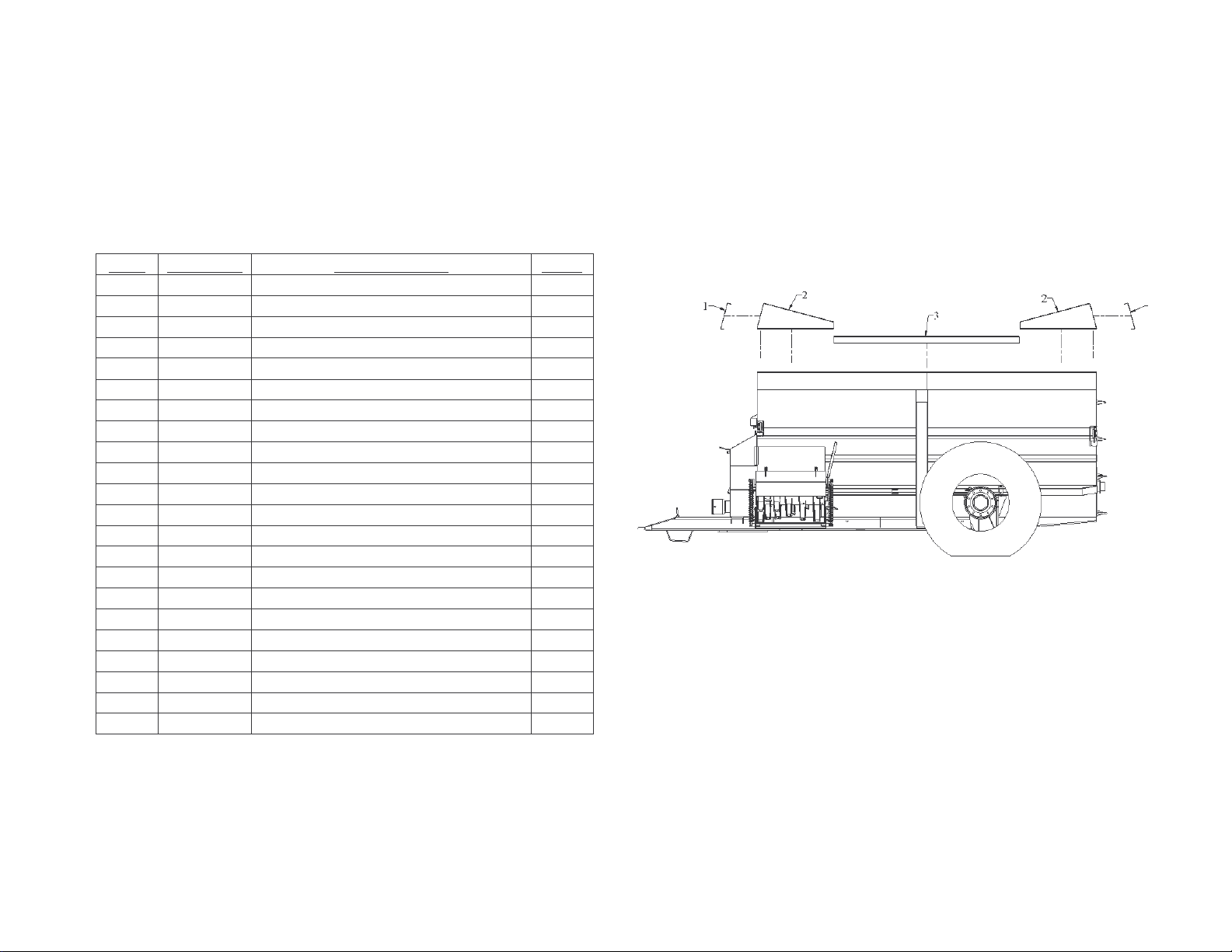
DUAL ALL MODELS ANTI-SPLASH ATTACHMENT
PART No. DESCRIPTION QTY.
REF.
131600 1300 & 1600 Splash Guard Assy
1 131104 Front & Rear Pressing 1300 & 1600 2
2 201602 Side Pressing LH 2
2 201605 Side Pressing RH 2
201600 2000 Splash Guard Assy
6
1 201601 Front & Rear Pressing 2000 2
2 201602 Side Pressing LH 2
2 201605 Side Pressing RH 2
571600 3000 Splash Guard Assy
1 571601 End Pressing 2
2 571610 Side Pressing 2
2 571620 Side Pressing 2
3 571630 Mid Pressing 2
132000 1 Decal Kit 1300
160400 1 Decal Kit 1600
202000 1 Decal Kit 2000
572000 1 Decal Kit 3000
SECONDARY DRIVE
PTO DRIVE
AUGER DRIVE
TENSIONER
ROTOR DRIVE
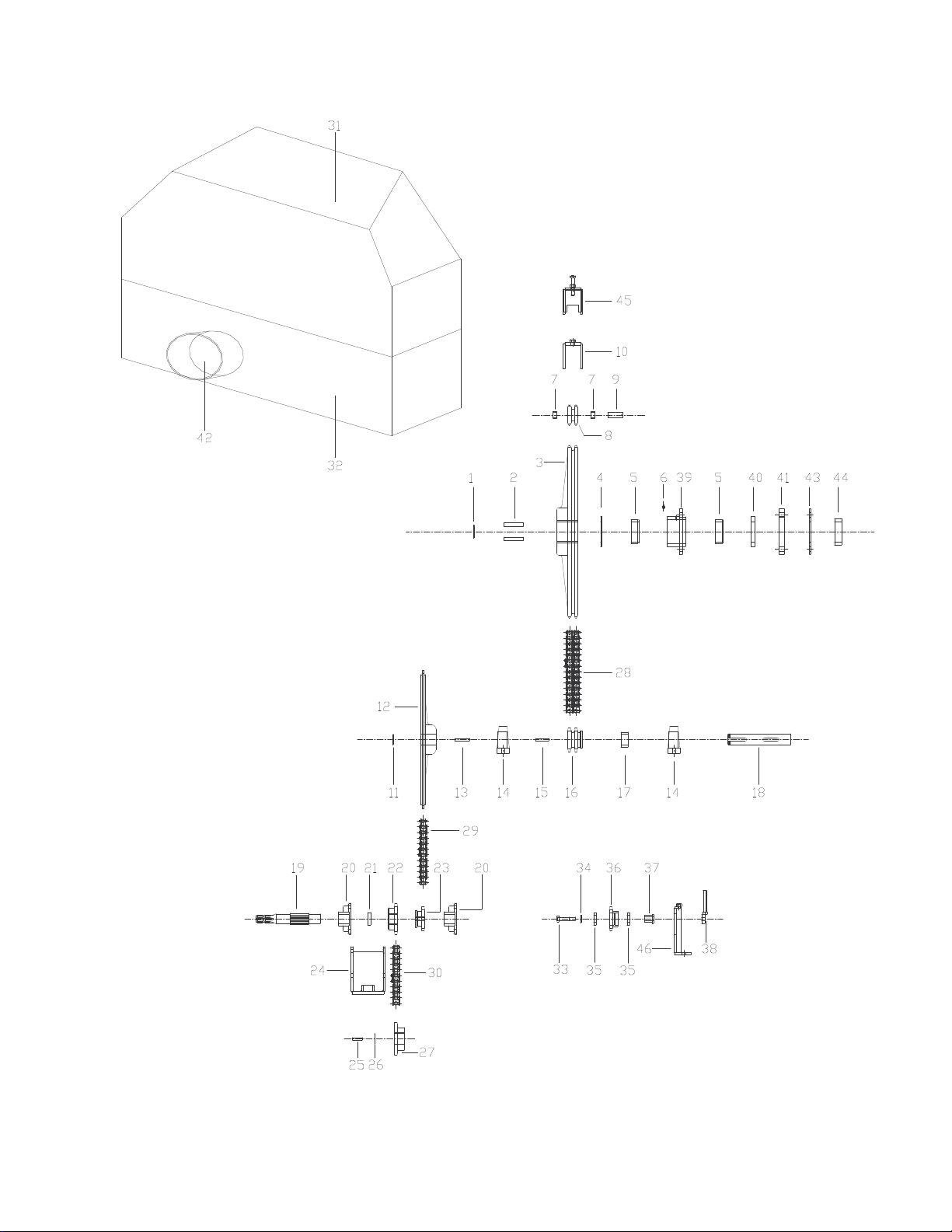
7

FRONT DRIVE ASSEMBLY
8
REF
PART No. DESCRIPTION QTY REF PART No. DESCRIPTION QTY
1 990525
2 110609 Key 2 29
3 110608 95th duplex keyed Sprocket 1 30
4 200506 Thrust Washer 1 31
5 200504 Front auger bearing nylon bush 1 32
6 990502 Grease nipple 1 33
7
8 110607 10th bushed duplex sprocket 1 35
9 120425 Chain adjuster pin 1 36
10 120287 Chain Tensioner Brkt 1 37
11 990524 2” Circlip 1 38
12 110605 76th simplex keyed sprocket 1 39
13 110610 Key 1 40
14 990105 MP2 bearing 2 41
15 110611 Key 1 42
16 110606 12th duplex keyed sprocket 1 43
17 120406 Spacer 1 44
18 120405 Lay Shaft 1 45
19 200510 Front Drive shaft 1 46
20 990107
21 120407 P.T.O. Box Spacer 1
22 200511 16th simplex sprocket 1
23 200512 12th splined sprocket 1
24 200929 P.T.O. box weld assy 1
25 110612 Key 1
26 990524 2” Circlip 1
27 200536 17th Sprocket 1
Oilite bearing (Inclusive with 110607) 2 34
3 ” Circlip
MSF 1 bearing
1 28
2
110604 Duplex chain 1
200537 Simplex chain 1
110603 Simplex chain 1
200422 Front guard top 1
200400 Front guard btm 1
Bolt M16 x 80 1
200978 Washer 1
990114 6006DDUCM Bearing (rhp) 2
200540 12th Idler Sprocket 1
200541 Bush 1
200979 Adjusting brkt 1
200801 Front auger bearing weld assy 1
200508 Felt seal 1
110434 Spacer 1
200425 P.T.O. Guard 1
200976 Sealing Plate 1
200513 Nylon Spacer 1
200131 Adjuster 1
200981 Tensioner Brkt weld assy 1
EXTRAS
990542 1” P simplex half link
990543 1” P simplex con/link
990544 1” P simplex inner link
990545 Duplex half link
990546 1” P duplex con/link
990547 1” P duplex inner link
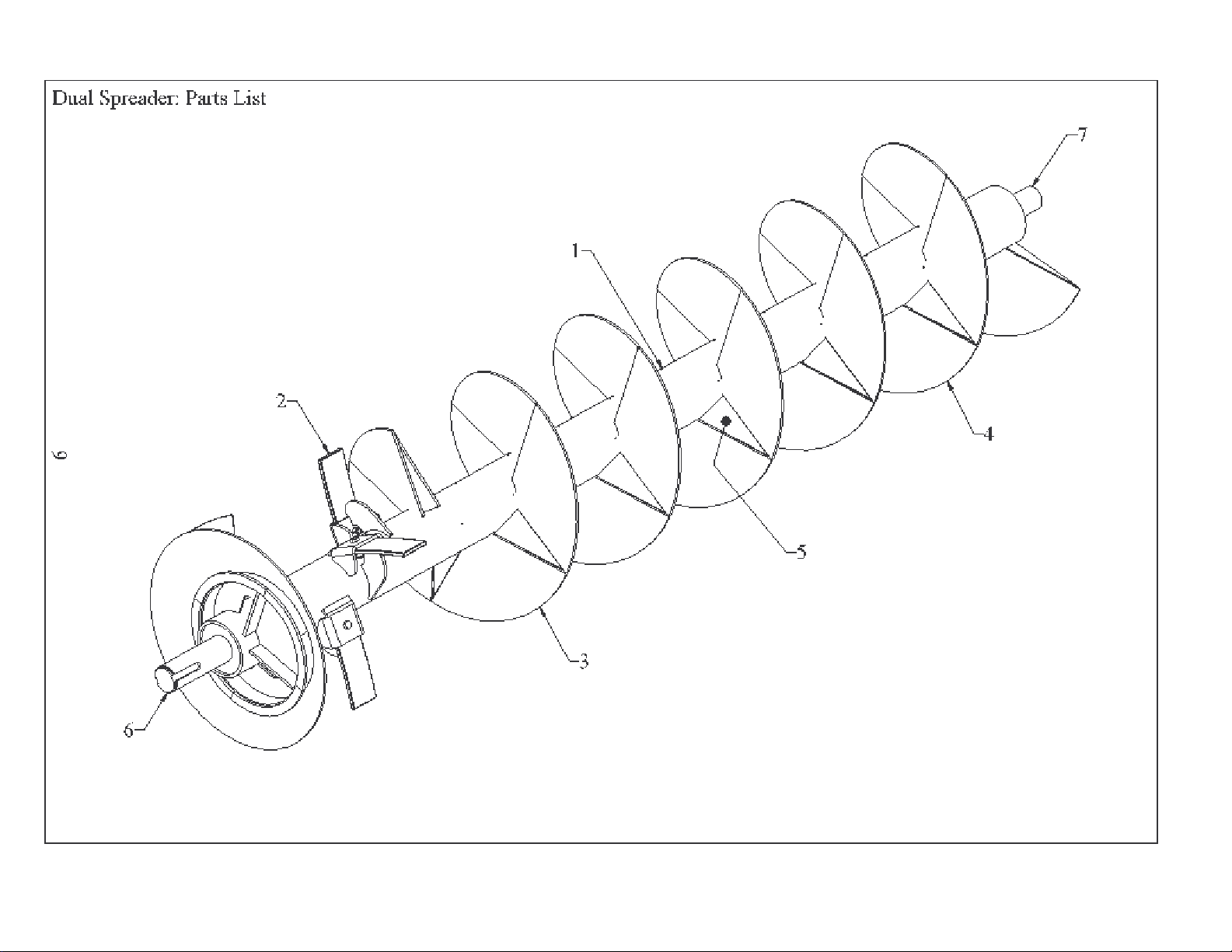

1300/1600/2000/3000 AUGER ASSY
PART NO DESCRIPTION QTY
10
REF
1 110300 Auger Assy 1300 1
1 160300 Auger Assy 1600 1
1 200300 Auger Assy 2000 1
1 570300 Auger Assy 3000 1
2 110315s Spring plate 4
3 110311 1300/1600 Dual Auger plate8 mm
4 110310 Auger plate 6 mm
5 110313 1300/1600 Dual Filler plate
6/12/15/15
11/10/11/16
17/22/26/32
6 110320 Front Shaft Assy (1300/1600) 1
6 200320 Front Shaft Assy (2000/3000) 1
7 110324 Rear Shaft Assy (1300/1600) 1
7 200324 Rear Shaft Assy (2000/3000) 1
PLEASE STATE THE CORRECT MACHINE SERIAL NUMBER AND PART NUMBER WHEN ORDERING PARTS


FEED OUT ROTOR ASSY
PART NO DESCRIPTION QTY REF PART NO DESCRIPTION QTY
REF
1
2
3
4
5
6
7
8
9
10
11
11a
11b
STANDARD ROTOR
201000 FEED OUT ROTOR W/ASSY 1 1 201401 FEED OUT ROTOR W/ASSY 1
201009 SPACER 1 2 201009 SPACER 1
990112 MSF2 BEARING 2 3 990112 MSF2 BEARING 2
200970 COVER PLATE 2 4 200970 COVER PLATE 2
201007 ROTOR TIP OUTER 10 7 201410 FRONT CHANNEL W/A 13
201008 ROTOR TIP INNER 18 8 201420 COMMON CHANNEL W/A 15
201001 FRONT & REAR CHANNEL 10 9 201022 FRONT SHAFT W/A 1
201002 INTERMEDIATE CHANNEL 18 10 201023 REAR SHAFT W/A 1
201022 FRONT SHAFT W/ASSY 1 12 201402 REPLACEABLE BLADE 28
201023 REAR SHAFT W/ASSY 1
201010 SHIM 1mm As Req
201010 SHIM 2mm As Req
201010 SHIM 3mm As Req
3000 ROTOR
PLEASE STATE THE CORRECT MACHINE SERIAL NUMBER AND PART NUMBER WHEN ORDERING PARTS


CAM ARM AND MOVING WALL
PART NO DESCRIPTION QTY REF PART NO DESCRIPTION QTY
REF
1
2
3
4
5
6
7
8
9
200715 Cam arm top 1
200701 Cam arm bottom 1
110253 Moving wall assy 1300/1600 1
200924 Guide Channel 1
990647 Chamfered Bolt 1
200918 2000 Moving wall assy 1
200994 Retaining Washer 1
200927 Pivot bush 1
M20 Nut and bolt 1
14
PLEASE STATE THE CORRECT MACHINE SERIAL NUMBER AND PART NUMBER WHEN ORDERING PARTS


ROTOR COVER AND TRAY
PART NO DESCRIPTION QTY REF PART NO DESCRIPTION QTY
REF
1
200946 Rotor Cover 1
2
200904 Tray 1
3
990515 Linch pin 2
4
200965 Link 2
5
200974 Spacer 2
6
205117 Anti splash plate 1
(fitted from 07/2006)
16
PLEASE STATE THE CORRECT MACHINE SERIAL NUMBER AND PART NUMBER WHEN ORDERING PARTS


REAR PLATE AND BEARING
PART NO DESCRIPTION QTY REF PART NO DESCRIPTION QTY
REF
1
2
3
4
5
6
200977 SEAL PLATE 1
200966 REAR PLATE ASSY 1
200509 FELT SEAL 1
200505 BEARING 2
200804 BEARING HOUSING 1
200807 COVER PLATE 1
18
PLEASE STATE THE CORRECT MACHINE SERIAL NUMBER AND PART NUMBER WHEN ORDERING PARTS


SLIDING DOOR CYLINDER AND TRACK
PART NO DESCRIPTION QTY REF PART NO DESCRIPTION QTY
REF
1
200953 SLIDING DOOR ASSY 1
2
200959 DOOR TRACK TOP 1
3
200961 1300/1600 CYLINDER BRKT 1
4
200502 2000 CYLINDER PLUS EXTENSION PIECE 1
5
200971 FRONT CYLINDER PIN 1
6
200972 REAR CYLINDER PIN 1
7
200956 SCRAPER PLATE 1
20
PLEASE STATE THE CORRECT MACHINE SERIAL NUMBER AND PART NUMBER WHEN ORDERING PARTS

21

1300, 1600 and 2000 Door Cylinder Assembly
PART NO DESCRIPTION QTY REF PART NO DESCRIPTION QTY
REF
1300, 1600
120502 Cylinder Assy 1
1
2
3
4
5
6
990600 Barrel 1 1
990601 Piston Rod 1 2
1" BSF Nut 1 3
Split pin 1 4
990602 Piston Head 1 5
990604 Gland Nut 1 6
7 SK/63/175/A Seal Kit 1 7
22
990622kramp Seal Kit 1
2000, 3000
200502 Door cylinder, complete 1
990617 Barrel Assembly 1
990618 Piston Rod 1
990619 1" B.S.F.Nut 1
Split Pin 1
990620 Piston Head 1
990621 Gland Nut 1
990622 Seal Kit 1
PLEASE STATE THE CORRECT MACHINE SERIAL NUMBER AND PART NUMBER WHEN ORDERING PARTS


TRAY TENSIONER LEVER ASSY
PART NO DESCRIPTION QTY REF PART NO DESCRIPTION QTY
REF
1 990616 LINCH PIN 2
2
3 200973 SPACER 2
4 200934 LEVER ASSY 1
5 120600 TENSION SPRING 2
24
PLAIN WASHERS 4
PLEASE STATE THE CORRECT MACHINE SERIAL NUMBER AND PART NUMBER WHEN ORDERING PARTS


DOOR INDICATOR ASSY
PART NO DESCRIPTION QTY REF PART NO DESCRIPTION QTY
REF
1
201123 COVER 1
2
201119 SPRING 1
3
201110 ROLLER 2
4
201106 INDICATOR 1
5
201104 ROLLER PIN 1
6
201118 WIRE ROPE AND CLEVIS 1
26
PLEASE STATE THE CORRECT MACHINE SERIAL NUMBER AND PART NUMBER WHEN ORDERING PARTS

27
BLUE
RED
GREEN & YELLOW
CLOSE DOOR – RED
OPEN DOOR – BLUE
BRAKE – GREEN / YELLOW

28
HYDRAULICS
PART NO DESCRIPTION QTY REF PART NO DESCRIPTION QTY
REF
1300 Dual Spreader
1 990201 Male Q/R coupling 2 1
2 990202 Female Q/R coupling brake 1 2
3 990206 ½Dowty Washer 3 3
4 990213 ¼" MMM 'T' Junction 1 4
6 200503 Brake cylinder 2 6
7 110502 Front Door Hose (5.76m) 1 7
8 110501 Rear Door Hose (6.63m) 1 8
9 110507 Brake hose to tractor (5.6m) 1 9
10 110504 RH Brake Hose (1.07m) 1 10
11 110503 LH Brake Hose (0.83m) 1 11
2000 Dual Spreader
1 990201 Male Q/R Coupling 2 1
2 990202 Female Q/R Coupling 1 2
3 990206 ½ Dowty Washer 3 3
4 990213 ¼ MMM 'T' Junction 1 4
6 990623 Brake Cylinder 2 6
7 200543 Door Hose (6.0m) 1 7
8
As 7 Door Hose (6.0m) 1 8
9 200544 Brake Hose to tractor (6.0m) 1 9
10 200545 RH Brake Hose (0.83m) 1 10
11 200546 LH Brake Hose (1.07m) 1 11
1600 Dual Spreader
990201 Male Q/R Coupling 2
990202 Female Q/R Coupling 1
990206 ½Dowty Washer 3
990213 ¼" MMM 'T' Junction 1
200503 Brake cylinder 2
110502 Front Door Hose (5.76m) 1
110501 Rear Door Hose (6.63m) 1
110507 Brake Hose to tractor (5.6m) 1
160506 RH Brake Hose (1.07m) 1
160505 L H Brake Hose (0.83m) 1
3000 Dual Spreader
990201 Male Q/R Coupling 2
990202 Female Q/R Coupling 1
990206 ½ Dowty Washer 3
990213 ¼ MMM 'T' Junction 1
990623 Brake Cylinder 2
200543 Door Hose (6.0m) 1
As 7 Door Hose (6.0m) 1
570544 Brake Hose to tractor (6.0m) 1
200545 RH Brake Hose (0.83m) 1
200546 LH Brake Hose (1.07m) 1
PLEASE STATE THE CORRECT MACHINE SERIAL NUMBER AND PART NUMBER WHEN ORDERING PARTS

29

DUAL LIGHTS
PART NO DESCRIPTION QTY
REF
1
201720 COMPLETE SET 1 LIGHTING CONNECTIONS
2
201721 TRACTOR LEAD 1
3
201722 7 PIN PLUG 2 PIN 1 GREEN LH INDICATOR LAMP
4
201723 7 PIN SOCKET 1 PIN 2 BLUE REAR FOG LAMP
5
201724 FRONT LIGHT COMPLETE 2 PIN 3 WHITE EARTH RETURN
8
201727 RH REAR LIGHT COMPLETE 1 PIN 4 YELLOW RH INDICATOR LAMP
9
201728 LH REAR LIGHT COMPLETE 1 PIN 5 BROWN RH TAIL & NO PLATE LAMP
PIN 6 RED STOP LAMP
PIN 7 BLACK LH TAIL & NO PLATE LAMP
30
BULBS
12VC5W-E8-3E2T118 REAR SIDE 12Volt 5Watt 2 off
2821LUXLAMP12VR5W 37R-E13-2A1 FRONT SIDE 12Volt 5Watt 2 off
CAB12VP214-E13-2A3 BRAKE AND INDICATOR 12Volt 21Watt 4 off
PLEASE STATE THE CORRECT MACHINE SERIAL NUMBER AND PART NUMBER WHEN ORDERING PARTS

31
3
1
4
1
2

3000 DUAL LIGHTS
PART NO DESCRIPTION QTY
REF
1
571700 COMPLETE SET 1 LIGHTING CONNECTIONS
2
201721 TRACTOR LEAD 1
252901BR FL
3
252901BR FL
4
REAR LIGHT 2 PIN 1 GREEN LH INDICATOR LAMP
FRONT LIGHT 2 PIN 2 BLUE REAR FOG LAMP
PIN 3 WHITE EARTH RETURN
PIN 4 YELLOW RH INDICATOR LAMP
PIN 5 BROWN RH TAIL & NO PLATE LAMP
PIN 6 RED STOP LAMP
PIN 7 BLACK LH TAIL & NO PLATE LAMP
32
BULBS
GE2619F FRONT LIGHT BULB
GE1057F ORANGE REAR LIGHT BULB
GE1077F RED REAR LIGHT BULB
PLEASE STATE THE CORRECT MACHINE SERIAL NUMBER AND PART NUMBER WHEN ORDERING PARTS

33

1300 & 1600 STUB AXLE
PART NO DESCRIPTION QTY REF PART NO DESCRIPTION QTY
REF
1
10053 Hub cap 2
2
14367 Split Pin 2
3 5802061 Castle Nut 2
4 7329307 Washer 2
5 1328981 Hub (8x22mm Stud) 2
6
505026 Outer Bearing 32211 2
7 3260193 Wheel Stud M18 16
8
10115 Wheel Nut M18 16
9 908408S Stub Shaft 2
10
34
11 6002064 Rear Washer 2
505027 Inner Bearing 32017 2
12 4008054 Spring 4
13 408100S Back Plate 2
14
15
Cam Shaft 2
Brake lever 2
17 4008053 Brake shoe & Linning 4
18
Grease nipple 2
19 WB1215 Sealing washer 2
20
Circlip 2
21 408TSM80 Drum (8 x 18Ø studs) 2
23 CBAG2032 Bearing Cam shaft 2
24
Circlip 2
PLEASE STATE THE CORRECT MACHINE SERIAL NUMBER AND PART NUMBER WHEN ORDERING PARTS

35

2000 STUB AXLE
PART NO DESCRIPTION QTY REF PART NO DESCRIPTION QTY
REF
1 3780000500 Support of brake 2 25 330201000A Castle Nut 2
2 3780000120 Brake cover 4 26 324101700A Cap 2
3 3407000000 Brake Shoes 4 27 3351016000 Wheel Stud 20
4 2237512000 Right Cam Shaft 1 28 3314011000 Wheel Nut 20
4 2237512100 Left Cam Shaft 1 29 4793032100 Axle Beam (1010XFR 406 x 120) 1
5 3472010100 Central Roller Brake 4 30 336400100A Spring Pin 2
6 3472010000 Fixed centre roller 4 31 4419047000 Hub (1010 XR – 1110 XF) 2
7 3161019000 Cam bush 4
8 3161019100 Fixed Bush 4
9 3392060000 Cam Stop Ring 4
10 3780000600 Cam Joint Ring 4
36
11 3492006300 Shoe brake spring (long) 2
12 3492006400 Shoe brake spring (short) 4
13 3516000000 Washer 2
14 3516000100 Washer 2
15 3261003500 Circlip 2
16 3261020000 Brake Spring Clip 2
17 3261021000 Brake roller clip 2
18 3182008000 Rod 2
19 3372004000 Grease Nipple 2
20 3492008500 Brake Return Spring 2
21 4560019200 Drum 2
22 4435500900 Axle Body Bracing Bush 2
23 443600160A Rear Washer (1010 XR – 1110 X) 2
24 3534026100 Bearing (32219) 4
PLEASE STATE THE CORRECT MACHINE SERIAL NUMBER AND PART NUMBER WHEN ORDERING PARTS

3
7
Shear Pin M8 x 55 x Grade 12.9
COMPLETE P.T.O. DRIVE SHAFT
10
990541
PART NO. 200539
 Loading...