

Harry Levy MELODY MOUSE Operator Instructions Manual
":?f!:j/!f;J!!f[i}~fllfA{~~~l!#!rf~tfi~~,'.
4uIj ~l2vlj
f}mUjf2mf2ntf!o.nt'lacto'l~td.
Units 1 - 4 Patricia Way, Pysons Road Industrial Estate
Broadstairs, Kent CT10 2LF England
"Telephone: (0843) 866464 Fax: (0843) 860144
MELODY
MOUSE
OPERATORS INSTRUCTIONS
For Version MMOUSE V25.11
Issued 8 July 1994
Remove any transit packing materials from the machine then site t~e
MELODY MOUSE on a smooth level floor.
Handle the machine with care. DO NOT subject it to shocks or damp.
DO NOT drop.
Ensure that ventilation holes or grill have at least 100mm
of clearance to allow free air flow for cooling.
(4")
Connect to the mains supply by fitting a suitable plug to the
machines bottom entry mains lead. The plug is to be fitted with a
5 Amp fuse. All wiring is to be carried out by a qualified
electrician.
Importanr - This machine must be grounded (earthed).
Mains Wiring
Brown
Blue
Green/yellow
Hot (live)
Neutral
Earth
As the colours of the wires in the mains lead of this appliance may
not correspond with the coloured markings identifying the terminals
in your plug, proceed as follows;
The wire which is coloured green and yellow must be connected to
the terminal in the plug which is marked with the letter E or by
the earth symbol, or coloured green or green and yellow.
The wire which is coloured blue must be connected to the terminal
which is marked with the letter N (Neutral).
The wire which is coloured brown must be connected to the terminal
which is marked with the letter L (Live or HOT).
Route the lead safely to a supply socket.
The MELODY MOUSE is designed for indoor use only, do not expose to
the weather.
Melody Mouse
page 1
Directors.H. J. LEVY. R. POVEY, P MARTIN, Secretary P. MARTIN.
Registered rn England No 1788744.
VAT. Reg. No. 397 8743 76
BACTA MEMBER

.,
Please note that the Melody Mouse control box is fitted with a
mains switch on the top of the box at the back. Care must be taken
not to touch the fan unit near the switch (certain export models
only). '-
IMPORTANT
Personnel other than skilled Service Engineers should disconnect
the machine from the mains supply before entering the machine for
any reason.
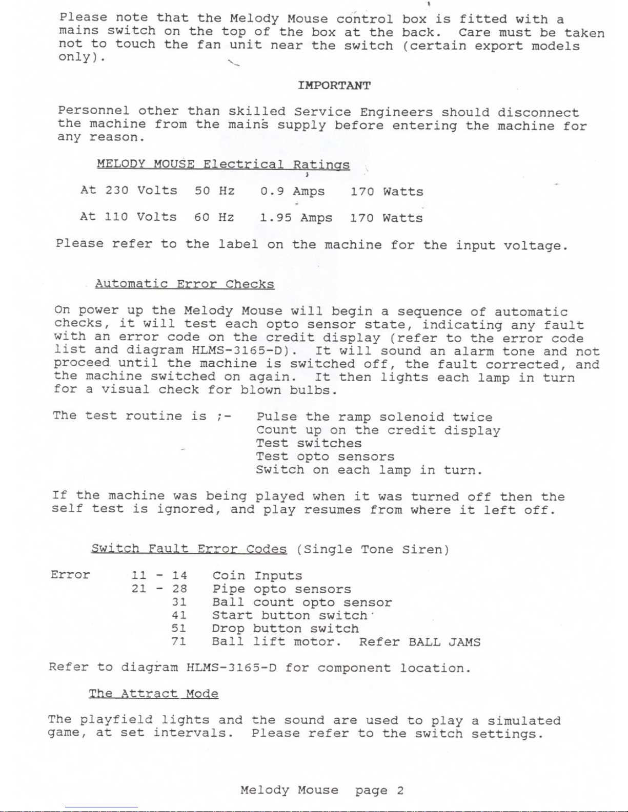
MELODY MOUSE Electrical Ratings
)
At 230 Volts 50 Hz
0.9 Amps
170 Watts
At 110 Volts 60 Hz
1. 95 Amps
170 Watts
Please refer to the label on the machine for the input voltage.
Automatic Error Checks
On power up the Melody Mouse will begin a sequence of automatic
checks, it will test each opto sensor state, indicating any fault
with an error code on the credit display (refer to the error code
list and diagram HLMS-3165-D). It will sound an alarm tone and not
proceed until the machine is switched off, the fault corrected, and
the machine switched on again. It then lights each lamp in turn
for a visual check for blown bulbs.
The test routine is ;-
Pulse the ramp solenoid twice
Count up on the credit display
Test switches
Test opto sensors
Switch on each lamp in turn.
If the machine was being played when it was turned off then the
self test is ignored, and play resumes from where it left off.
Switch Fault Error Codes (Single Tone Siren)
Error
11 - 14
21 - 28
31
41
51
71
Coin Inputs
Pipe opto sensors
Ball count opto sensor
Start button switch"
Drop button switch
Ball lift motor. Refer BALL JAMS
Refer to diagram HLMS-3165-D for component location.
The Attract Mode
The playfield lights and the sound are used to playa simulated
game, at set intervals. Please refer to the switch settings.
Melody Mouse
page 2
.,
Please note that the Melody Mouse control box is fitted with a
mains switch on the top of the box at the back. Care must be taken
not to touch the fan unit near the switch (certain export models
only). ~
IMPORTANT
Personnel other than skilled Service Engineers should disconnect
the machine from the mains supply before entering the machine for
any reason.
MELODY MOUSE Electrical Ratings
)
At 230 Volts 50 Hz
0.9 Amps
170 Watts
At 110 Volts 60 Hz
1. 95 Amps
170 Watts
Please refer to the label on the machine for the input voltage.
Automatic Error Checks
On power up the Melody Mouse will begin a sequence of automatic
checks, it will test each opto sensor state, indicating any fault
with an error code on the credit display (refer to the error code
list and diagram HLMS-3165-D). It will sound an alarm tone and not
proceed until the machine is switched off, the fault corrected, and
the machine switched on again. It then lights each lamp in turn
for a visual check for blown bulbs.
The test routine is i-
Pulse the ramp solenoid twice
Count up on the credit display
Test switches
Test opto sensors
Switch on each lamp in turn.
If the machine was being played when it was turned off then the
self test is ignored, and play resumes from where it left off.
Switch Fault Error Codes (Single Tone Siren)
Error
11 - 14
21 - 28
31
41
51
71
Coin Inputs
Pipe opto sensors
Ball count opto sensor
Start button switch'
Drop button switch
Ball lift motor. Refer BALL JAMS
Refer to diagram HLMS-3165-D for component location.
The Attract Mode
The playfield lights and the sound are used to playa simulated
game, at set intervals. Please refer to the switch settings.
Melody Mouse
page 2
 Loading...