

Page 1

Digital Radios
260-668107-001
StarMAX™
6000 SERIES MOBILE BASE STATIONS USER MANUAL
Page 2

Page 3

StarMAX™ 6000 Series
Mobile Base Stations User
Manual
Rel. 4.1.1 (GA Preliminary Draft)
Page 4

StarMAX™ 6000 Series Mobile Base Stations User Manual
260-668107-001 December 2009
This manual incorporates features and functions provided with the StarMAX™ 6000 Series, Release
4.1.1. (GA Preliminary Draft).
Copyright © 2009 by Harris Stratex Networks, Inc.
All rights reserved. No part of this publ ication may be reproduced, transmitted, transcribed, stored in a
retrieval system, or translated into any language or computer language, in any form or by any means,
electronic, magnetic, optical, chemical, manual or otherwise, without the prior written permission of
Harris Stratex Networks Inc. To request permission, contact techpubs@hstx.com
Warranty
Harris Stratex Networks makes no representation or warranties with respect to the contents hereof and
specifically disclaims any implied warranties or merchantability or fitness for any particular purpose.
Further, Harris Stratex Networks reserves the right to revise this publication and to make changes from
time to time in the content hereof without obligation of Harris Stratex Networks to notify any person of
such revision or changes.
.
Safety Recommendations
The following safety recommendatio ns must be c onsidered to avoid injuries to persons and/or damage
to the equipment:
1. Installation and Service Personnel: Installation and service must be carried out by authorized
personnel who have the technical training and experience necessary to be aware of any hazardous
operations during installation and service, and of measures to avoid any danger to themselves, to
any other personnel, and to the equipment.
2. Access to the Equipment: Access to the equipment in use must be restricted to service personnel
only.
3. Safety Norms: Local safety regulations must be used if mandatory. Safety instructions in this
document should be used in addition to the local safety regulations. In the case of conflict between
safety instructions stated in this manual and those indicated in local regulations, mandatory local
norms will prevail.
4. Service Personnel Skill: Service personnel must have received adequate technical training on
telecommunications and in particular on the equipment this manual refers to.
Trademarks
All trademarks are the property of their respective owners.
ii Harris Stratex Networks
Page 5

StarMAX™ 6000 Series Mobile Base Stations User Manual
Contact Information
Sales and Sales Support:
For sales information, contact one of the Harris Stratex Networks headquarters, or find your regional
sales office at http://www.harrisstratex.com/contact.
Corporate Headquarters
North Carolina, USA
Harris Stratex Networks, Inc.
Research Triangle Park
637 Davis Drive
Morrisville, North Carolina 27560
United States
Phone: + 1 919-767-3230
Fax: + 1 919-767-3233
Toll Free for Sales Inquiries:
+ 1 888-HSTX-NOW (888-478-9669)
International Headquarters
Singapore
Harris Stratex Networks (S) Pte. Ltd.
17, Changi Business Park Central 1
Honeywell Building, #04-01
Singapore 486073
Phone: +65
Fax: + 65 6496 0999
Sales Inquiries:
+1-321-674-4252
6496 0900
Customer Service:
For customer service, contact one of the regional Technical Help Desks listed below.
Americas Technical Help
Desk
Harris Stratex Networks
120 Rose Orchard Way
San Jose, CA 95134
U.S.A.
EMEA Technical Help Desk Asia Pacific Technical Help
Desk
Harris Stratex Networks
4 Bell Drive
Hamilton International
Technology Park
Blantyre, Glasgow, Scotland
G72 0FB
United Kingdom
Harris Stratex Networks
Bldg 10, Units A&B
Philexcel Industrial Park
M. Roxas Hi-way
Clark Freeport Zone
Philippines 2023
Phone:+1 210 561 7400
Toll-free in US:
+1 800 227 8332
Fax: +1 408 944 1683
TAC.AM@hstx.com
Or you can contact your local Harris Stratex Networks office. Contact information is available on our
website at: www.harrisstratex.com/support/customer/.
260-668107-001 December 2009 iii
Phone:+44 1698 714 073
Fax: +44 1698 717 204
TAC.EMEA@hstx.com TAC.APAC@hstx.com
Phone:+63 45 599 5192
Fax: +63 45 599 5196
Page 6

FCC Notices
1. The StarMAX Base Station must be professionally installed and maintained.
2. This equipment has been tested and found to comply with the limits for a Class A digital device,
pursuant to Part 15 of the FCC rules. These limits are designed to provide reasonable protection
against harmful interference when the equipment is operated in a commercial environment. This
equipment generates, uses and can radiate radio frequency energy and, if not installed and used in
accordance with the instruction manual, may cause harmful interference to radio communications.
Operation of this equipment in a residential environment is likely to cause harmful interference in
which case the user will be required to correct the interference at his own expense.
3. Notes specific to the 2.496 – 2.69GHz band:
•The StarMAX Base Station (with radio models 8200-25, frequency range 2.496 – 2.603GHz and
8200-26, frequency range 2.583-2.690GHz ) is compliant with FCC CFR47, Part 27..
•To ensure compliance with the FCC RF exposure requirements, a minimum d istance of 3.72 meters
must be maintained between the base station antenna and any persons whilst the unit is
operational. This calculation is based on the maximum conducted power and maximum antenna
gain.
•The 2.5GHz and 2.6GHz Base Stations have been tested and certified for use with an XPOL antenna
with a maximum gain of 18dBi and Omni antennas with a maximum gain of 13dBi.
4. Notes specific to the 3.65 – 3.675GHz band:
•The StarMAX 3.6GHz Base Station complies with FCC CFR47, Part 90, Subpart Z
•For FCC CFR47, Part 90, Subpart Z, StarMAX operation is restricted to the 25MHz band 3.65GHz
– 3.675GHz.
•To ensure compliance with the FCC RF exposure requirements, a minimum d istance of 25cm must
be maintained between the base station antenna and any persons whilst the unit is operational at
5MHz and 34cm for 10MHz operation. This calculation is based on the EIRP limits within Part 90,
Subpart Z.
•The 3.6GHz Base Station has been tested and certified for use with an XPOL antenna with a
maximum gain of 16.5dBi or Omni antennas with a maximum gain of 13dBi.
•For FCC CFR47, Part 90, Subpart Z operation between 3.65 – 3.675GHz, the EIRP must be limi ted
to 5W for 5MHz operation and 10W for 10MHz. The conducted power must be limited during
installation according to the gain of the antenna used . As the conducted power t olerance is +/- 1dB
for StarMAX the power should be reduced by 1dB from the absolute EIRP limits of 5W and 10W.
For example, if operating in a 10MHz channel and using a 16.5dBi antenna, the conducted power
would be limited to a maximum of 22.5dBm.
RF Exposure guidelines
The following MPE (maximum permissible exposure) calculations have been produced in accordance
with the guidelines of EN 50383/EN 50385. These calculations represent examples only and do not
include every possible combination of output power and antenna gain.
Occupational is defined as: “The occupationally exposed population consists of adults who are generally
exposed under known conditions and are trained to be aware of the potential risk and to take
appropriate precautions”.
iv Harris Stratex Networks
Page 7

StarMAX™ 6000 Series Mobile Base Stations User Manual
Transmit Power
(dB m )
A nt en na Ga in (dB i) Co m p lia n ce
Bound ary General
Public (m)
Compliance
Boundary
Occupational (m)
Transmit Power
(dB m )
Antenna Gain (dBi) Compliance
Bound ary General
Compliance
Boundary
2.3 – 2.7GH z
40.0 20.7 3.72
40.0 9.0 0.97
36 .0 20 .7 2 .35
36.0 9.0 0.61
3.3 – 3.8GHz
Public (m)
36.0 23.0 3.1
36.0 9.0 0.61
1.6 7
0.43
1.0 5
9.27
Occupational (m)
1.3 7
0.27
260-668107-001 December 2009 v
Page 8
WARNING
Making adjustments and/or modifications to this equipment that are not in
accordance with the provisions of this instruction manual or other
supplementary documentation may result in personal injury or damage to
the equipment, and may void the equipment warranty.
AVERTISSEMENT
Tout réglage ou modification faits à cet équipement hors du cadre édicté
par ce guide d’utilisation ou par toute autre documentation supplémentaire
pourraient causer des blessures ou endommager l’équipement et peut
entraîner l’annulation de sa garantie.
WARNUNG
Die an diesen Geräten gemachte Einstellungen und/oder Änderungen,
welche nicht gemäß dieser Bedienungsanleitung, oder gemäß anderen
zusätzlichen Anleitungen, ausgeführt werden, können Verletzungen oder
Materialschäden zur Folge haben und eventuell die Garantie ungültig
machen.
ATENCIÓN
Llevar a cabo ajustamientos y/o modificaciones a este equipo, sin seguir
las instrucciones provistas por este manual u otro documento adicional,
podría resultar en lesiones a su persona o daños al equipo, y anular la
garantía de este último.
vi Harris Stratex Networks
Page 9

Contents
CHAPTER 1, INTRODUCTION & OVERVIEW
Abbreviations & Definitions ............................................................................ 1-1
Conventions................................................................................................. 1-4
Overview of a StarMAX™ Base Station............................................................. 1-5
Introducing StarMAX™ .............................................................................. 1-5
StarMAX™ 6000 Series Mobile Base Station Building Blocks............................1-6
Brief Description of a StarMAX™ Base Station............................................... 1-7
Network Management System for the StarMAX™ Base Station........................1-7
Specifications........................................................................................... 1-8
CHAPTER 2, GETTING STARTED
Commissioning the Base Station.....................................................................2-1
Configuring the Basic Parameters................................................................ 2-1
Operational Verification of the Base Station.................................................. 2-1
Required Information ................................................................................ 2-2
Logging-in In to the Base Station for the First Time........................................... 2-4
Accessing CLI by using Telnet......................................................................... 2-5
Understanding Command Modes................................................................. 2-6
Getting Help................................................................................................. 2-7
Using the No and Default Forms of Commands.................................................. 2-8
CHAPTER 3, CONFIGURING THE BASE STATION
Configuring Basic IP Parameters ..................................................................... 3-1
Configuring ASN ...........................................................................................3-1
Configuring DNS Client.................................................................................. 3-2
Configuring FTP Client ................................................................................... 3-2
Configuring ntp ............................................................................................ 3-3
Configuring Interface Fastethernet.................................................................. 3-3
Configuring Interface Gigabitethernet..............................................................3-3
Configuring Broadcast ................................................................................... 3-3
Configuring Multicast..................................................................................... 3-4
Configuring NI power ....................................................................................3-4
Configuring NSP ...........................................................................................3-4
Configuring NAP ...........................................................................................3-4
Configuring MIMO......................................................................................... 3-5
Configuring VLAN ID ..................................................................................... 3-5
Configuring preamble-index ........................................................................... 3-5
Configuring frequency-fractional-reuse ............................................................3-5
Configuring handover-advertisement ............................................................... 3-6
Configuring handover dcdTriggers ................................................................... 3-6
Configuring handover neighbor-bs-entry.......................................................... 3-6
Configuring Synchronization........................................................................... 3-6
Rebooting the IDU Modules............................................................................ 3-8
Provisioning the RF Interface.......................................................................... 3-8
Enabling WiMAX Interface.......................................................................... 3-8
260-668107-001 December 2009 vii
Page 10

Configuring Channel Bandwidth and Frequency3-8
Configuring Output Power3-9
Configuring MAC3-9
Configuring Link Adaptation3-9
Setting MAC Frame3-10
Configuring TDD Scheduler3-10
Configuring and Managing User Access3-11
Adding Users3-11
Deleting Users3-12
Changing Password3-12
Changing Access Level3-12
CHAPTER 4, MONITORING AND MANAGING THE BASE STATION
Monitoring Environment Status4-1
Managing Subscriber Stations4-2
Management VLANs4-3
Configuring mgmt-vlan-mode4-4
Managing Configuration Files and Softw are4-5
Software Upgrade4-5
Software Downgrade4-6
Configuration File Manipulation4-6
Configuring Syslog and SNMP Traps to Monitor System Performance4-7
Configuring Syslog Service4-7
Configuring SNMP Trap Service4-9
APPENDIX A, CONNECTION REQUEST SIGNALING
GeneralA-1
Operating ModesA-1
viii
Harris Stratex Networks
Page 11

Chapter 1. Introduction &
Overview
This manual provides you with a basic overview of the StarMAX™ 6000 Series Mobile
Base Stations and helps you in commissioning and basic system operation of the base
station.
This manual is intended for use by Base Station users, mostly service provider staff and
Harris Stratex Networks support staff. Basic understanding of the WiMAX 802.16e
2005 standards and a basic IP-based networking knowledge are the prerequisites for
the user manual. This manual provides a detailed explanation of system configuration
and maintenance, as well as requisite system operation details.
For more information, refer to the StarMAX™ 6000 Series Mobile Base Stations
Installation Guide.
Abbreviations & Definitions
Abbreviations Description
ACB ATCA carrier board
ASN Access Service Network
BE Best Effort
BS Base Station
CIR Committed Information Rate
CINR Carrier-to-Interface plus Noise Ratio
CLI Command Line Interface
CPE Customer Premises Equipment
CPRI Common Public Radio Interface
CSN Core Service Network
DC Direct Current
EIRP Equivalent Isotropic Radiated Power
EMS Element Management System
FEC Forward Error Correction
GND Ground
GPS Global Positioning System
260-668107-001 December 2009 1-1
Page 12

Chapter 1. Introduction & Overview
Abbreviations Description
GSSU GPS Synchronization Supply Unit
IDU Indoor Unit
IF Intermediate Frequency
IPMI Intelligent Platform Management Interface
LED Light Emitting Diode
LVDS Low Voltage Data Signal
MAC Medium Access Control
MIMO Multiple-Input and Multiple-Output
MPU Main Processor Unit
MS Mobile Station
NMS Network Management System
Nrt-PS Non Real Time Polling Services
ODU Outdoor Unit
PLL Phase Locked Loop
PMP Point To Multipoint
PMPF PMP Card with Fiber Optics Interface
POST Power On Self Test
PPS Pulses Per Second
PS Power Supply
RO Read Only
RF Radio Frequency
R/W Read/Write
RSSI Receive Signal Strength Indicator
SELV Safety Extra Low Voltage
SFP Small Form-factor Pluggable
SNMP Simple Network Management Protocol
SoC System on Chip
SS Subscriber Station
STC/MRC Space Time Coding / Max. Ratio Combining
TDM Time Division Multiplexing
TTL Transistor-Transistor Logic
VEE Virtual End-to-End
1-2 Harris Stratex Networks
Page 13

StarMAX™ 6000 Series Mobile Base Stations User Manual
Abbreviations Description
WEEE Waste Electronic Electric Equipment
260-668107-001 December 2009 1-3
Page 14
Chapter 1. Introduction & Overview
Conventions
The following conventions are used in the document to help you to identify special
terms.
Convention Usage Example
Bold The following screen
elements:
Button
List
Drop-down menu
Courier
New
Computer output text
Click OK.
HSX_bs#configure access-list 2
permit 11:22:33:44:55:66
00:00:00:00:00:00 22:33:44:55:66:77
00:00:00:00:00:00
Courier
Bold
Courier
Italic
Italic Description of figures and
< > Mandatory parameters HSX_bs# show card <unit number>
[ ] Optional parameters HSX_bs# configure ip address <ip-address>
| Mutually exclusive choices in
User input text
Variable in command that
you may replace with other
values, as required
tables, Book title and
emphasis, Cross References
a command or a code
>HSX_bs#exit
To make a new directory, enter:
prompt> mkdir new_directory_name
ProductCodes
Refer to User Manual for more information.
[subnet mask]
HSX_bs#reboot 1|2|3
The Note format is used for clarification or to point out specific text or
instructions in the procedure or description.
The Caution format is used for a Warning or a Caution. The
information that follows alerts personnel to possible damage to
equipment or interruption of service, or a violation of a legal
requirement.
1-4 Harris Stratex Networks
Page 15

StarMAX™ 6000 Series Mobile Base Stations User Manual
The Stop format indicates a pause in the procedure to perform some
other task. The procedure continues once you have completed the other
task.
Overview of a StarMAX™ Base Station
Introducing StarMAX™
The StarMAX™ 6000 is a series of Base Station solutions, which offers a possibility to
install 16d and 16e WiMAX blades into a 1U or 4U chassis. Together with the
StarMAX™ 8200 series of the 16e ODUs, it is used to build a flexible network of
multi-sectored WiMAX 16e Base Stations (BS).
The Solution is designed in a modular split indoor/outdoor (IDU/ODU) form. A High
bandwidth CPRI interface (fiber optic) is used between an IDU and an ODU. The power
supply for the ODU is delivered over a separate cable.
Harris Stratex Networks’ Mobile WiMAX solution supports mobile voice and data
services, and can be used in a carrier grade nationwide network or on an enterprise
grade campus network. A StarMAX™ System complies with the 802.16e-2005
specifications and ensures interoperability with the systems built in accordance with
the same specifications. This enables the opportunity to use Subscriber Stations and
Mobile Stations of different vendors. The StarMAX™ solution is wave 2 compliant and
certified by the WiMAX Forum. While the system is designed to offer mobile services,
the same can also offer fixed, nomadic or portable services without any loss of
efficiency.
A StarMAX™ 6000 Series Base Station indoor unit is a compact 1U or 4U rack mount
Base Station. The solution is scalable for dense urban to rural deployments with
provision for multi-sectored deployments with a dense frequency reuse. It gives the
flexibility of deploying a lower number of sectors initially and addition of new sectors
later on if necessary. The solution is available in various frequency bands in order to
meet the requirements of different markets.
All connections are made on the front panel to ease the installation and maintenance
and enable back-to-back or wall positioning of the equipment. The chassis is designed
for carrier grade deployments with redundant power supply and a field replaceable
FAN unit.
The StarMAX™ 8200 Series Outdoor unit delivers a high output power with an
advanced antenna technology like MIMO 2x2 Matrix A/B for better coverage and
service quality in demanding mobile environments. Together with the StarMAX™
range of Subscriber Stations, StarMAX™ NMS and StarMAX™ ASN the Base Station
offers a complete mobile solution for the operator.
260-668107-001 December 2009 1-5
Page 16
Chapter 1. Introduction & Overview
StarMAX™ 6000 Series Mobile Base Station Building
Blocks
The StarMAX™ 6000 Series of Mobile Base Stations use a number of different blades
to support different Base Station configurations, network structures and
implementation scenarios. The building block can be divided in different groups of
products, according to the functions they are delivering:
a. StarMAX 6000 chassis or MSAN chassis
b. StarMAX 6000 16 e WiMAX Network Processing Blades
c. StarMAX™ 4940 external GSSU unit
d. StarMAX™ 4930 GPS unit and a cable splitter for synchronization purpose
e. StarMAX™ 6080 Synch blade
f. cables (RF jumper cable, IF cable, antenna cable)
g. Outdoor Unit (ODU)
Beside those stated above, the StarMAX™ 8200 ODU part is necessary to form a
complete Base Station, which is covered elsewhere in this document.
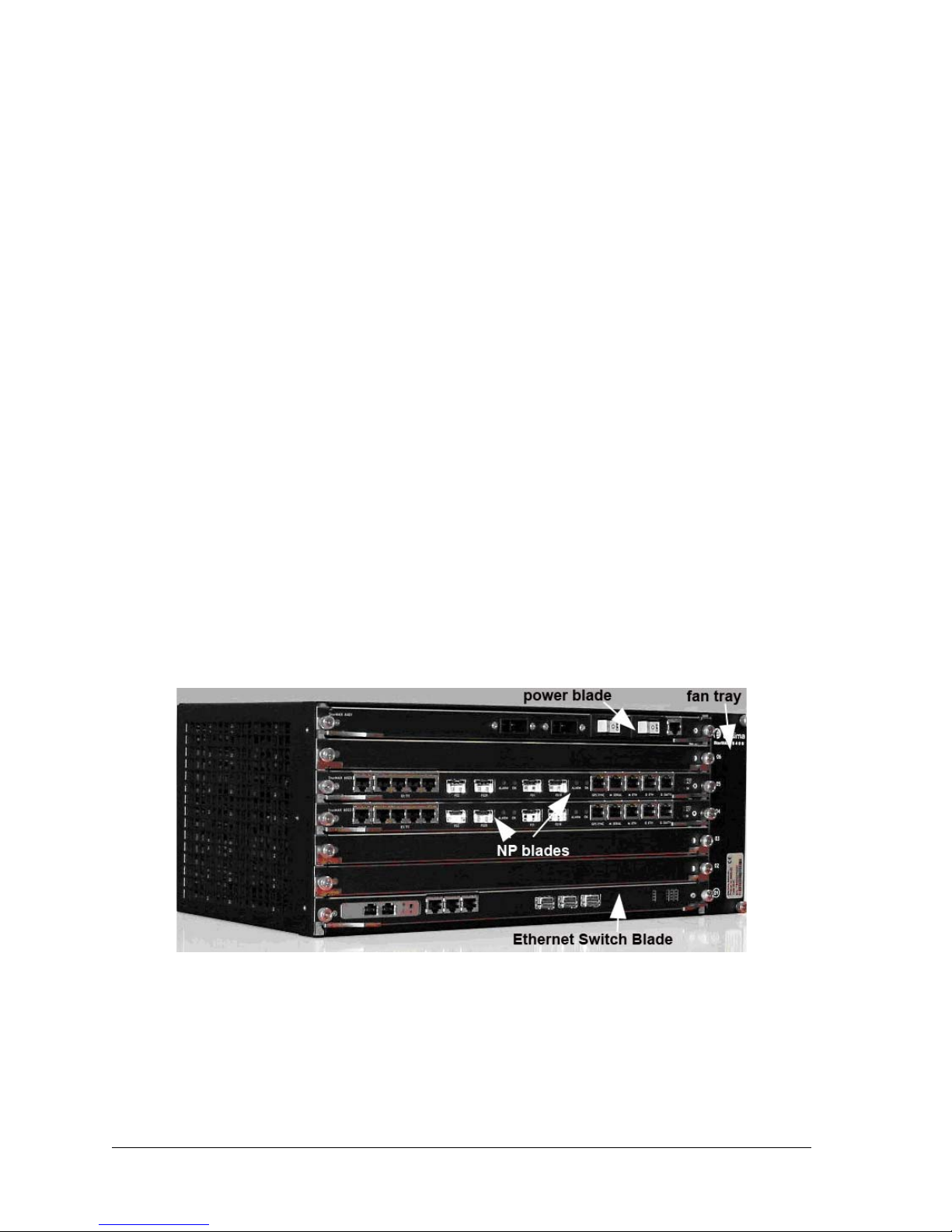
The StarMAX™ Chassis
An operator has a choice of using a single blade 6100 chassis or a multi-blade 6400
chassis. Since there is a requirement for a Synchronization blade, it is recommended
that the operator use the 6400 chassis, because it ensures a stable network in case of
future growth.
Figure 1-1. StarMAX™ Mobile Base Station
The MSAN Chassis
The MSAN chassis is much like the 6400 chassis with one major difference: there is no
master slot. The NMS displays the MSAN chassis as a 3rd party chassis.
1-6 Harris Stratex Networks
Page 17

StarMAX™ 6000 Series Mobile Base Stations User Manual
Brief Description of a StarMAX™ Base Station
A Base Station installed at the Operator premises provides data connectivity to all
provisioned and registered Subscriber stations.
The StarMAX™ 6000 Series Base Station has a rugged industrial design with dual
redundant power supply inlets and removable cooling fan tray to ensure reliability and
high performance in adverse conditions. Redundant WiMAX configurations can be
built by adding more base systems to the stack or designating an available WiMAX
point-to-multipoint module within a base system as a hot standby.
The StarMAX™ 6000 Series base station has implemented several enhanced modes of
WiMAX for performance differentiation, to receive diversity through MRC and
transmit diversity through STC and for payload header suppression for increasing IP
payload throughput.
Based on Harris Stratex Networks’ core intellectual property a wide range of RF options
are supported, including 2.3/2.5/3.3/3.5 GHz bands in Time Division Duplexing
(TDD) modes of operation.
The Harris Stratex Networks base station also supports portability and mobility in the
WiMAX network by enabling TRUFLE™ te chnology which supports features such as a
state handover of a subscriber station from one base station to another without losing
IP connectivity and TCP sessions.
Network Management System for the StarMAX™ Base
Station
The Harris Statex Networks network management system, StarMAX™ NMS
implements full Fault, Configuration, Accounting, Performance, and Security (FCAPS)
functionalities and is implemented on a client-server architecture based on the SNMP
v2. This provides an easy integration of the NMS into the operator's management and
billing systems environment.
The Provisioning Manager keeps the access lists and implements service level
agreements. It can configure min/max bandwidth, QoS, priority and rate limiting per
subscriber station or service flow. Supported classes of service are Best Effort (BE),
UGS, nrt-PS, eRtps and Rt-PS.
260-668107-001 December 2009 1-7
Page 18

Chapter 1. Introduction & Overview
Specifications
This section details the specifications of the StarMAX™ system.
Table 1-1. General Radio Specifications
8200-2.3G 8200-2.5G 8200-3.3G 8200-3.5G
Frequency Range
Frequency Setting
Step Size
2300-2400 MHz 2496-2690 MHz 3300-3400 MHz 3400-3600 MHz
250 kHz
Frequency Stability
(Int. Synch. Mode)
Duplexing Method
Multiple Access
Method
Modulation
Air Interface
Standard
Compliance
Bandwidth
Frame Length
Emission
Designation
a. Any bandwidth between 1,5MHz and 14MHz with a granularity of 250kHz can be supported.
a
b
EqC-PET =
EqC-SET =
EqC-EMO =
EqC-ChS =
EqC-FR =
EqC-STN =
4ppm
TDD
TDMA
OFDMA, 1024/512 FFT with adaptive subcarrier modulation:
QPSK-1/2, QPSK-3/4, QAM16-1/2, QAM16-3/4, QAM64-1/2, QAM64-2/3,
QAM64-3/4, QAM64-5/6
IEEE 802.16e-2005 OFDMA 1024/512 FFT
5MHz; 7MHz; 10MHz
5ms
O
DM
variable 2, 4, 6
5MHz to 10MHz
2.3-2.4; 2.5-2.69 GHz; 3.3-3.4GHz; 3.41GHz-3.6GHz
CS
5M00X7W, 7M00X7W, 10M0X7W
b. Frame lengths of 2,5ms and 4ms can be supported.
1-8 Harris Stratex Networks
Page 19

StarMAX™ 6000 Series Mobile Base Stations User Manual
Table 1-2.
Maximum Output Power at Antenna Port
Transmit Radio Specifications
a
2x+36dBm,
2x+39dBm,
2x+40dBm
Output power adjusting range
Output Power Setting Step Size
Output Power Tolerance
TX Signal EVM at Maximum Output Power
TX Noise Spectral Density at Max. Power
Adjacent Channel Power Ratio
Alternate Channel Power Ratio
b
b
Unwanted Emissions at Antenna Port
a. RMS power of data symbols regardless of the modulation used.
b. At maximum output power
25dB
1dB
+1dB / -2dB
< -31dB
< -119dBm/Hz
< -40dBc
< -65dBc
< -50dBm
Table 1-3. Receive Radio Specifications
Noise Figure
Max. RX Level at Antenna Port, BER<1E-6
Max. Tolerable RX Level at Antenna Port
Receive Sensitivity (BER<1E
-6
, BW=10 MHz,
QPSK1/2)
Adjacent Channel Rejection (16QAM-3/4)
Non-Adjacent Channel Rejection (16QAM-3/4)
Image Rejection
Unwanted Emissions at Antenna Port
4dB
-45dBm
-10dBm
-98dBm
Better than 11 dB
Better than 30 dB
70dB
< -60dBm
260-668107-001 December 2009 1-9
Page 20

Chapter 1. Introduction & Overview
Table 1-4.
Interface Specifications
6012-01 & 6012-00 (WiMAX
blade)
CPRI Connector
Antenna Connector
Data Port
Duplex LC (SFP Module) ODC -2
- N(f) – 50
1 x 10/100BT (RJ-45)
1 x 1000BT (RJ-45)
backplane
GPS Synchronization
Front - (RJ-45)
backplane
Power Supply
2 x 3 Contact connector CPC Series 5
Table 1-5. TMN Specifications
Out of Band Management
In Band Management
SNMP Agents
Software Upgrade
Configuration Upload
8200 (ODU)
-
-
NMS using SNMP, CLI using Telnet, SSH
NMS using SNMP, CLI using Telnet, SSH
Built-in SNMP agent v2c, standard and Harris
Stratex Networks proprietary MIBs
Using FTP/TFTP, centralized upgrade from NMS
Using FTP/TFTP
1-10 Harris Stratex Networks
Page 21

StarMAX™ 6000 Series Mobile Base Stations User Manual
Table 1-6.
Dimensions
Mechanical and Electrical Specifications
StarMAX 6022 + 6100
(1 slot IDU chassis)
44x444x250 176x430x280 410x294x154
StarMAX 6022 + 6400
( 6 slot IDU chassis)
(HxWxD) [mm]
Interfaces WAN - 1GBE & 10
MNG - 10
Clock - 1PPS or GPS on
100BaseT on RJ-45
100BaseT & Serial on
RJ-45
BNC
PWR - -48VDC
IDU/ODU - optical (LC)
Weight (max) [kg] 5.2 10 13
Power Supply
-48V ÷ -60V -48V
Voltage
Power
Consumption,
max.
37W 6022 (2 sector blade, 4
blades max.)
-28W
6400 (chassis + fan unit)
- 48W
6080 (opt. sync. blade)
– 25W
6090 (opt. IP switch
blade)
– 25W
StarMAX 8200
(RRH)
-
36/39dBm
205/225W max
155/175W for
70:30 TDD split
Rack Pole
Requirements
IDU: 19” and 23” ODU up to 120
mm pole
diameter
Table 1-7. Environmental Specifications
Operating Temperature
StarMAX 6xxx (IDU
chassis)
--5°C ÷ +45°C -40°C ÷ +50°C
StarMAX 8200
(ODU)
Range
Operating Humidity Range 5% ÷ 95% 10% ÷ 100%
EN 300 019 reference class 3.2 extended class 4.1E
Storage Temperature Range -45C ÷ +85C
Storage Humidity Range 8% ÷ 100%
EN 300 019 reference class 1.3E
Transportation EN 300 019 class 2.3
260-668107-001 December 2009 1-11
Page 22

Chapter 1. Introduction & Overview
Table 1-8.
EMC
Safety
Table 1-9. GPS Sync Blade Holdover duration for 6080-02-00-01 StarMAX
Standard Compliance
EN 301 489-1, EN 301 489-4
EN 60 950
6080 GPS Receiver Blade, 8hr Hold
Over
Maximum phase
error PPS
7 µsec 10 h 2 h 30mn
10 µsec 14 h 3h 1h
25 µsec 20 h 7h 2h 15mn
Table 1-10. GPS Sync Blade Holdover duration for 6080-00-00-01 StarMAX
Constant temp. + or – 3°C + or – 10°C
6080 GPS Receiver Blade, 24hr
Hold Over
Maximum phase
error PPS
7 µsec > 24h 5 h 2h
10 µsec > 24h 7 h 3h
Constant temp. + or – 3°C + or – 10°C
25 µsec > 24h 13h 7h
1-12 Harris Stratex Networks
Page 23

Chapter 2. Getting Started
Commissioning the Base Station
Configuring the Basic Parameters
This section explains the process of configuring the basic system parameters after
system is installed. Refer to the StarMAX™ 6000 Series Mobile Base Stations
Installation Manual for the installation details.
Configure the system management IP address, IP sub-net mask and gateway IP
address through the serial port. Refer to Configuring Basic IP Parameters on
page 3-1.
Configure the list of the authorized users for the system operation and maintenance
through the Java based NMS or CLI. Refer to Configuring and Managing User
Access on page 3-11.
After you have configured the basic parameters, you can configure the additional
parameters and services through the Java based NMS or CLI through serial port or a
telnet session.
Operational Verification of the Base Station
Table 2-1. Base Station LED verification
LED Description
OOS (red) • Unlighted: The PMPF image is not running.
• Blinking: The PMPF is running a self test.
• Solid: The PMPF is functional.
ACT (green) Illuminates, when base station is functional (activity).
SR (blue) Illuminates, when 48V is applied to the system and power is not
provided to the system side.
LED F01, F02
OK (green)
LED F01, F02
ALARM (red)
LED GPS SYNC
OK (green)
• Unlighted: The PMPF image is not running.
• Blinking: The PMPF is running a self test.
• Solid: The PMPF is functional.
• Unlighted: The PMPF is functional.
• Blinking: The PMPF has a wrong configuration/not configured.
• Solid: The PMPF has a permanent fault (broken).
• Unlighted: PLL not locked to the PPS.
• Lighted: PLL locked to the PPS.
260-668107-001 December 2009 2-1
Page 24

Chapter 2. Getting Started
LED Description
YNC ALARM
(red)
Table 2-2.
LED Description
System LEDs
RED LED (ALARM:
SYNC MODULE
OSCILOQUARTZ)
GREEN
LED(OK:SYNC
MODULE
(OSCILOQUARTZ)
RE D L ED ( OOS:
SYNC blade)
GREEN LED (ACT:
SYNC blade)
BL UE LED (S R:
SYNC blade)
LED GPS SYNC OK
(green)
LED Description
RJ45
SYNC LED
• Unlighted: PPS signal present
• Lighted: no PPS signal present
• Error status: Antenna not connected, GPS not locked, PPS
not present
• OK status: GPS locked, PPS provided).
“Out Of Service Status”:Blade is not operational.
• “Active” :Blade is working as specified.
• SYNC blade not powered ON :Secondary power not
present on Sync blade.
• Unlighted: PLL not locked to the PPS.
• Lighted: PLL locked to the PPS.
GREEN LED (SYNC
IN)
YELOW LED (SYNC
IN)
GREEEN LED
(E.MNG and
E.SYNC)
YELOW LED
(E.MNG and
E.SYNC)
• PPS signal
• 12V present
• ACTIVITY
• SPEED STATUS ON: 100Mbs OFF: 10Mbs
Verifying Data Connectivity
To verify data connectivity from the end-user's Personal Computer (PC) connected to
any synchronized subscriber station, try to connect to the Internet.
Required Information
Table 2-3 lists parameters required to bring the base station to a minimal operational
state.
2-2 Harris Stratex Networks
Page 25

StarMAX™ 6000 Series Mobile Base Stations User Manual
Table 2-3.
Required Information before Starting the Operation
Item Parameters How/What to Update
Management Port
(mandatory)
FTP Server
(optional)
Admin User Login Info
(mandatory)
IP Address
Subnet Mask
Gateway
FTP User name
FTP password
Username
(Preconfigured)
192.168.1.100
255.255.255.0
192.168.1.1
<Selected FTP server Login User name>
<Selected FTP server Login Password>
admin
admin
Password
(Preconfigured)
Privilege User
Login Info
(mandatory
Frequency and Bandwidth
provisioning
Privilege Username
(Preconfigured)
Privilege User Password
(Preconfigured)
Frequency in kHZ
Bandwidth in kHz
root
telsimawl
(Note: Default Password for “root”
username can be changed by root login)
2500000 for 2.5 GHz
10000 for 10 MHZ
260-668107-001 December 2009 2-3
Page 26

Chapter 2. Getting Started
Logging-in In to the Base Station for the First
Time
You must use the serial port on the front panel of the StarMAX™ 6000 (IDU) to
manage the base station when you log in for the first time. This ensures that the basic
parameters (for example the IP address) can be configured to enable Telnet access to
the CLI or Java base NMS (i.e. NMS).
Ensure that you have the following items before you log in:
• A VT-100 compatible terminal, or a PC with terminal emulation software
• A DB-9 to RJ-45 serial cable
To log in:
1. Connect a serial cable from the COM port on your computer to the serial port
(RJ-45 connector) on the IDU.
2. Configure the terminal or emulation program as follows:
• Port: COM1 (the one you connected serial cable to),
• Data rate: 115200,
• Data: 8 bits,
• Parity: none,
•Stop: 1 bit,
• Flow control: none.
• Activate connection.
3. Connect the IDU to the power supply and wait until the IDU responds with a login:
prompt.
4. To log into the admin user mode type the following:
>Login:<name>
>Password:<password>
The default admin username and password are set to the same value: admin.
To log into the privilege user mode type the following:
>Login:<rootusername>
>Password:<rootpassword>
The default privilege username is root. The default privilege password is
telsimawl.
The Default Password of the privileged user root can be changed.
After successful login, the IDU responds with a BS_bs# prompt. That means you are
ready to enter CLI commands to control the base station. The following sections show
you how to use CLI commands to configure and monitor the base station.
2-4 Harris Stratex Networks
Page 27

StarMAX™ 6000 Series Mobile Base Stations User Manual
If a user is already logged into admin user mode and wants to upgrade access rights to
that of privilege user mode, enter the following command:
>BS_bs#enable
>Enter root password:<rootpassword>
>enabled#
To log out enter the following command:
>enable#exit
>C:\
Accessing CLI by using Telnet
To access a CLI prompt via Telnet perform the following steps:
1. Open command prompt.
2. Type the following command:
C:\>telnet <IP address>
Here <IP address> is the base station management port IP address. A login: prompt
will appear.
3. Log in as described in Logging-in In to the Base Station for the First Time
on page 2-4.
After successful login, IDU responds with a BS_bs# prompt. That means you are ready
to enter CLI commands to control the base station. Following sections show how to use
CLI commands to configure and monitor the base station.
To log out use the following command:
>enable#exit
>C:\
Exiting from telnet CLI prompt as described above ends the active telnet
session.
CLI is used to access the Base Station software from a configuration and monitoring
perspective. CLI is divided into different modes; the commands available to you at any
given time depend on the mode you are currently in. Entering a question mark (?) at
the CLI prompt allows you to obtain a list of further command nodes available based
on the sequence of command nodes or parameters entered.
260-668107-001 December 2009 2-5
Page 28

Chapter 2. Getting Started
Understanding Command Modes
When you log in to the CLI as an administrative user, you are in administrative
command mode, while when you log in as privilege user, you are in privilege co mmand
mode respectively. Administrative user mode contains only a limited subset of
commands. If you are already logged in as an administrative user and want to have
access to all commands, you must enter the privileg ed command mode by using enable
command which authenticates the privileged user password. From the privileged
command mode you can issue any command - administrative or privileged mode - or
you can enter global configuration mode. Commands are not saved when the base
station system reboots.
The table below describes the different user levels and the associated description on the
node accessibility (access privileges are in the increasing order).
Table 2-4. BS System Users Privilege Categories
Privilege Category Category Description
ACCT-RO Display of accounting related information (configuration parameters and
statistics information).
IP-RO Display of IP related information (configuration parameters and statistics
information).
RF-RO Display of Radio Freq uency related information (configuration parameters
and statistics information).
ACCT-ROD Display of accounting related debug information.
IP-ROD Display of IP related debug information.
RF-ROD Display of RF related debug information.
ACCT-RW Accounting parameter configuration/write access as well as display of
configuration parameters, statistics and debug information.
IP-RW IP parameter configuration/write access as well as display of configuration
parameters, statistics and debug information.
RF-RW Parameter configuration/write access as well as display of configuration
parameters, statistics and debug information.
Configuration modes enable you to create/re-create the running configuration file. The
generated running configuration file can be saved to the startup configuration file,
these commands in the startup configuration files are executed when the system is
rebooted to configure the system to pre-reboot state. Please refer to Managing
Configuration Files and Software on page 4-5 for more details.
To enter specific configuration modes, you must start at global configuration mode.
From global configuration mode, you can enter a different configuration mode, for
example, interface configuration mode by entering node name “interface” and an
interface specific node name, for example, “fastethernet”, “wimax” etc. Refer to
Appendix B for further details.
The table below describes how to access and exit various common command modes of
the CLI. It also shows examples of the prompts displayed for each mode.
2-6 Harris Stratex Networks
Page 29

StarMAX™ 6000 Series Mobile Base Stations User Manual
Table 2-5.
Command
Mode
Administrative
or user
Privilege Log in as privilege user or use the
Global
Configuration
Interface
Configuration
Accessing and Exiting Commands Modes
Access method Prompt Exit Method
Log in BS_bs# exit command
enable command from
administrative command mode
From privilege mode, use the
configure privileged command.
From administrative mode, use
enable command to authenticate
followed by configure privileged
command.
From global configuration mode,
specify an interface using an
interface command.
Getting Help
enabled# or
BS_bs#
BS_bs
(config)#
BS_bs
(config-if)#
exit command
Use quit command or
press Ctrl-Z.
To return to global
configuration mode, use
the quit command.
CLI offers the context-sensitive help feature by the user entering a question mark (?) at
the CLI shell with or without CLI nodes. This displays a list of further commands
(nodes) options available in terms of nodes/parameters at any given context based on
the user nodes/parameters entry.
To get specific help for a command mode, a command, a keyword, or an argument, use
one of the commands listed in the table below.
Table 2-6. Help Commands
Command Purpose
CLI command node
string?
CLI command node
string<Tab>
? Provides a list of commands that are available subsequent to a particular
command ? Provides a list of keywords or arguments that you must enter next on the
Provides a list of commands that begin with a particular character string.
(No space between ‘CLI command node string’ and question mark and note
that CLI command node string can be partial.)
Completes the CLI command node string if the command name specified in
the string is partial.
CLI command mode.
command line. (Space between command and question mark.)
260-668107-001 December 2009 2-7
Page 30

Chapter 2. Getting Started
Using the No and Default Forms of
Commands
Many configuration commands have a no form. In general, use the no form to disable
a function. Use the command without the no keyword to re-enable a disabled function
or to enable a function that is disabled by default.
2-8 Harris Stratex Networks
Page 31

Chapter 3. Configuring the Base
Station
This chapter explains the process of configuring various parameters of the base station.
Configuring Basic IP Parameters
To configure basic management port IP parameters enter the following commands:
BS_bs#config
>BS_bs(config)#ip address <ipaddr> <subnetmask> <gateip address>
>BS_bs(config)#quit
>BS_bs#
ip address <ip> <netmask> <gateway>
where:
•
<ipaddr> is the IP address assigned to the base station management port in IP
address format, for example, 192.168.182.253
•
<subnetmask> is the subnet mask assigned to the base station management port in
IP address format, for example 255.255.255.0
•
<gateip address> is the gateway IP address assigned to the base station
management port in IP address format, for example 192.168.182.1
To view base station basic IP parameters enter the following command:
>BS_bs#show ip
Configuring ASN
To configure ASN use the following commands:
configure asn / show asn
forwarding-options - Specify the ASN data plane type
gateway - Specifies ASN-GW(ASN gateway) parameters
quit - Exit ASN configuration mode
r6-timer - Specify timeout values for R6 Message Timers
tunnel - Specify ASN data plane tunnel parameters
wimax-sector - Specify WiMAX sector specific parameters
260-668107-001 December 2009 3-1
Page 32

Chapter 3. Configuring the Base Stati o n
For detailed description and examples please refer to the StarMAX™ 6000 Series
Mobile Base StationsCommand Line Interface.
Configuring DNS Client
To enable DNS client service on the base station it is mandatory to be logged into the
privilege user mode. Use the following steps.
In the first step set primary DNS server that will be used by DNS client. Optionally,
alternate DNS server can be set. Use the following commands:
>BS_bs#config
>BS_bs(config)#ip dns server <dnsserver> primary
where:
•
<dnsserver> is DNS server IP address provided by your network administrator, for
example 192.168.180.8
•
Primary flag is used to set the primary DNS server IP address provided by your
network administrator, for example 192.168.180.8
Next, enable DNS client using this command:
>BS_bs(config)#ip dns enable
At this point DNS client is functional. Additionally, domain name can be stored:
>BS_bs(config)#ip dns domain <domain>
where <domain> is the domain name used by DNS client, for example hstx.com
To view DNS client settings enter this command:
>BS_bs#show ip dns
Configuring FTP Client
To set the default username and password for the FTP client on the base station you will
use when accessing the FTP server, it is mandatory to be logged into the privilege user
mode. Use the following commands:
>BS_bs#config
>BS_bs(config)#ip ftp username <name>
>BS_bs(config)#ip ftp password
Enter ftp password: <password>
where:
•
<name> is a FTP server authentication username, used as the default username for
ftp put or ftp get CLI commands
3-2 Harris Stratex Networks
Page 33

• <password> is a FTP server authentication password corresponding to username,
used as the default password for authentication for ftp put or ftp get CLI commands.
Configuring ntp
To enable, to configure ntp server and to configure time zone use the following
commands:
configure ntp / show ntp
For detailed description and examples please refer to the StarMAX™ 6000 Series
Mobile Base Stations Command Line Interface.
StarMAX™ 6000 Series Mobile Base Stations User Manual
Configuring Interface Fastethernet
To configure internet fastethernet use the following commands:
configure interface fastethernet / show interface fastethernet
For detailed description and examples please refer to the StarMAX™ 6000 Series
Mobile Base Stations Command Line Interface.
Configuring Interface Gigabitethernet
To configure internet gigabitethernet use the following commands:
configure interface gigabitethernet /show interface gigabitethernet
For detailed description and examples please refer to the StarMAX™ 6000 Series
Mobile Base Stations Command Line Interface.
Configuring Broadcast
To enable broacast control use the following commands:
configure broadcast-control-enable
configure broadcast-echo
260-668107-001 December 2009 3-3
Page 34

Chapter 3. Configuring the Base Stati o n
For detailed description and examples please refer to the StarMAX™ 6000 Series
Mobile Base Stations Command Line Interface.
Configuring Multicast
To enable multicast control use the following commands:
configure multicast-control-enable
configure multicast-echo
For detailed description and examples please refer to the StarMAX™ 6000 Series
Mobile Base Stations Command Line Interface.
Configuring NI power
To set the default NI power per subcarrier use the following command:
configure interface wimax 1/1 uplink default-ni-power
For detailed description and examples please refer to the StarMAX™ 6000 Series
Mobile Base Stations Command Line Interface.
Configuring NSP
To configure nsp use the following command:
configure interface wimax 1/1 nsp
For detailed description and examples please refer to the StarMAX™ 6000 Series
Mobile Base Stations Command Line Interface.
Configuring NAP
To configure nap use the following command:
configure interface wimax 1/1 nap
For detailed description and examples please refer to the StarMAX™ 6000 Series
Mobile Base Stations Command Line Interface.
3-4 Harris Stratex Networks
Page 35

StarMAX™ 6000 Series Mobile Base Stations User Manual
Configuring MIMO
To enable mimo and to set mimo profile use the following command:
configure interface wimax 1/1 mimo enable
For detailed description and examples please refer to the StarMAX™ 6000 Series
Mobile Base Stations Command Line Interface.
Configuring VLAN ID
To set Home VLAN ID for all the CPEs connected to this Base Station and to set Home
VLAN ID for all the Subscriber Stations connected to this base station use the following
command:
configure vlan-policy home-vid
For detailed description and examples please refer to the StarMAX™ 6000 Series
Mobile Base Stations Command Line Interface.
Configuring preamble-index
To configure preamble-index use the following command:
configure interface wimax 1/1 preamble-index
For detailed description and examples please refer to the StarMAX™ 6000 Series
Mobile Base Stations Command Line Interface.
Configuring frequency-fractional-reuse
To configure frequency-fractional-reuse use the following command:
configure interface wimax 1/1 frequency-fractional-reuse
For detailed description and examples please refer to the StarMAX™ 6000 Series
Mobile Base Stations Command Line Interface.
260-668107-001 December 2009 3-5
Page 36

Chapter 3. Configuring the Base Stati o n
Configuring handover-advertisement
To configure handover-advertisement use the following command:
configure interface wimax 1/1 handover advertisement-enable
For detailed description and examples please refer to the StarMAX™ 6000 Series
Mobile Base Stations Command Line Interface.
Configuring handover dcdTriggers
To configure handover dcdTriggers use the following command:
configure interface wimax 1/1 handover dcdTriggers
For detailed description and examples please refer to the StarMAX™ 6000 Series
Mobile Base Stations Command Line Interface.
Configuring handover neighbor-bs-entry
To configure handover neighbor-bs-entry use the following command:
configure interface wimax 1/1 handover neighbor-bs-entry
For detailed description and examples please refer to the StarMAX™ 6000 Series
Mobile Base Stations Command Line Interface.
Configuring Synchronization
The following options are available to synchronize the IDU into the system.
3-6 Harris Stratex Networks
Page 37

StarMAX™ 6000 Series Mobile Base Stations User Manual
• IDU is the synchronization master and the source. This option is only for test
purposes and should not be used during normal operation. To perform this
configuration enter the following commands:
>BS_bs#config
>BS_bs(config)# synchronization
>BS_bs(sync)#mode master
>BS_bs(sync)#source generated <freq>
>BS_bs(sync)#quit
>BS_bs(config)#quit
>BS_bs#
where <freq> determines the synchronization source frequency. Options are:
• -1- 1 Hz
• IDU is the synchronization master and the source is generated externally by GPS
receiver and connected to GPS SYNC port on the IDU front panel. To perform this
configuration enter the following commands:
>BS_bs#config
>BS_bs(config)# synchronization
>BS_bs(sync)#mode master
>BS_bs(sync)# source external frontpanel
>BS_bs(sync)#quit
>BS_bs(config)#quit
>BS_bs#
If this option is used in StarMax6400 chassis only one blade must be set
to Master mode all others must be configured as slave.
• Two or more IDU blades in StrarMAX 6400 chassis are connected to GPS receiver
thru GSSU unit. To perform this configuration enter the following commands:
>BS_bs#config
>BS_bs(config)# synchronization
>BS_bs(sync)#mode slave
>BS_bs(sync)# source external frontpanel
>BS_bs(sync)#quit
>BS_bs(config)#quit
To view IDU synchronization settings enter the following command:
>BS_bs#show synchronization
260-668107-001 December 2009 3-7
Page 38

Chapter 3. Configuring the Base Stati o n
Rebooting the IDU Modules
To reboot one of the IDU modules enter the following command:
>BS_bs#reboot <slotnumber>
Enter the reason [Max characters not to exceed 1024]: testing the
system
Confirm:[Y/N]
Y
>BS_bs#
where <slotnumber> defines reboot target module. Options are:
•1 - ACB (IDU main board)
• 2 - PMP card in slot #1
• 3 - PMP card in slot #2
Provisioning the RF Interface
Enabling WiMAX Interface
To enable the wimax interface with basic configuration at IDU such as enable MAC
frames and basic ODU configuration, use the following commands:
BS_bs#config or >enabled#config
BS_bs(config)#interface wimax <slotinterfacenumber> enable
BS_bs(config)#quit
BS_bs#
where:
•
<slotinterfacenumber> is the wimax interface ID. Options are:
• -1/1 - wimax interface connected to interface 1 on IDU front panel
• -1/2 - wimax interface connected to interface 2 on the IDU front panel
Configuring Channel Bandwidth and Frequency
To configure RF interface (sector) channel b andwidth and frequency it is mandato ry to
be logged into the privilege user mode. Use the following commands:
>BS_bs#config or >enabled#config
>BS_bs(config)#interface wimax <slotinterfacenumber>
>BS_bs(config-i/f-W)#frequency <frequency>
>BS_bs(config-i/f-W)#bandwidth <bandwidth>
>BS_bs(config-i/f-W)#quit
>BS_bs#
where:
3-8 Harris Stratex Networks
Page 39

StarMAX™ 6000 Series Mobile Base Stations User Manual
• <slotinterfacenumber> is the wimax interface ID. Options are:
• -1/1 - ODU connected to PMP Interface 1 port on the IDU front panel
• -1/2 - ODU connected to PMP Interface 2 port on the IDU front panel
•
<frequency> is the channel frequency in KHz, for example 3342500 to set 3.3425
GHz
•
<bandwidth> is the channel bandwidth in MHz, for example 3500 to set 3.5 MHz
To view channel bandwidth, frequency, operational status, or administrative status at
the WiMAX interface enter the following command:
> BS_bs#show interface wimax config
Configuring Output Power
To configure output power for one of the RF interfaces (sectors) it is mandatory to be
logged into the privilege user mode. Use the following commands:
>BS_bs#config or >enabled#config
>BS_bs(config)#interface wimax <slotinterfacenumber>
>BS_bs(config-i/f-W)#downlink tx-power 20
>BS_bs(config-i/f-W)#quit
>BS_bs#
where:
•
<slotinterfacenumber> is the wimax interface ID. Options are:
• -1/1 - ODU connected to PMP 1 interface port on the IDU front panel
• -1/2 - ODU connected to PMP 2 interface port on the IDU front panel
•
<txpower> is the output power of RF transmitter in ODU in dBm(txpower range
30-40, for example 30 to set 30 dBm
To view output power enter the following command:
>BS_bs#show interface wimax downlink-config <slotId>
where:
•
<slotId> - Slot number in multiple blade chassis and default to “1” for this release.
Configuring MAC
Configuring Link Adaptation
This set of commands offers you to enable or disable automatic uplink or downlink
adaptation, according to the radio conditions and specified thresholds, hysteresis and
protection.
BS_bs#configure interface wimax 1/1 uplink link-adaptation
BS_bs#configure interface wimax 1/1 downlink link-adaptation
link-adaptation
260-668107-001 December 2009 3-9
enable or disable link adaptation
Page 40

Chapter 3. Configuring the Base Stati o n
where:
•
<slotinterfacenumber> is the WiMAX interface ID. The options are:
• -1/1 - ODU connected to PMP 1 interface port on the IDU front panel
• -1/2 - ODU connected to PMP 2 interface port on the IDU front panel
•
<linkadapthys> is the CINR hysteresis in dB when upgrading the FEC. Allowed
value is floating in the range 0 to 100.
•
<linkadaptionprot> is the CINR protection in dB against implemented CINR. The
allowed value is floating in the range from 0 to 100.
Setting MAC Frame
To set the G-ratio of the cyclic prefix start and the duration of the MAC frame for one
of the RF interfaces (sectors) enter the following commands.
>BS_bs#config or >enabled#config
>BS_bs(config)#interface wimax <slotinterfacenumber>
>BS_bs(config-i/f-W)#cyclic-prefix <cyclic-prefix>
>BS_bs(config-i/f-W)#frame-duration <frame-duration>
>BS_bs(config-if)#quit
>BS_bs#
where:
•
<slotinterfacenumber> is the wimax interface ID. Options are:
• -1/1 - ODU connected to PMP 1 interface port on the IDU front panel
• -1/2 - ODU connected to PMP 2 interface port on the IDU front panel
•
<cyclic-prefix> the G-ratio of the cyclic prefix start. Options are:
•-1/8
•
<frame-duration> is the MAC frame duration. Options are:
•-5ms
For StarMAX 8200 1/8 and 5ms are supported.
Configuring TDD Scheduler
TDD scheduler allows you to set dynamic configuration of the adaptive s tate of the split
of the TDD frame between the uplink and the downlink. When adaptive split is enabled,
the sub-frame sizes are dynamically adapted to the load if each link, and the split
parameter specifies the equilibrium point when both links are under congestion. When
disabled, the sizes of the downlink and uplink sub-frames are constant and are defined
by the split parameter. A static split is useful for BWA, when reusing a single frequency.
A dynamic split results in better bandwidth use.
3-10 Harris Stratex Networks
Page 41

StarMAX™ 6000 Series Mobile Base Stations User Manual
To enable adaptive TDD split for one of the RF interfaces (sectors) enter the following
commands.
>BS_bs#config or >enabled#config
>BS_bs(config)#interface wimax <slotinterfacenumber>
>To set the size of the downlink sub-frame as a percentage of the frame being split
enter:
>BS_bs(config-i/f-W)#tdd-split <tddsplit>
>BS_bs(config-i/f-W)#quit
>BS_bs#
where:
•
<slotinterfacenumber> is the wimax interface ID. Options are:
• -1/1 - ODU connected to PMP 1 interface port on the IDU front panel
• -1/2 - ODU connected to PMP 2 interface port on the IDU front panel
<tddsplit> the size of the downlink sub-frame as a percentage of the frame being
•
split, integer in the range from 0 to 100.
Configuring and Managing User Access
Adding Users
To add the CLI system user it is mandatory to be logged into the privilege user mod e or
privilege equal to or above ACCOUNTING-RW. Use the following commands:
>BS_bs#config
>BS_bs(config)#user add <name> <access>
>BS_bs(config)#user password <name>
Load-Setup#configure user add test_user rf-rw
User account created successfully.
Default Password: test_user
Load-Setup#
where:
•
<name> is the username added to CLI system user list
•
<access> is an enumerated defining user access level. Options are:
• One of the nine access privilege category (For details refer to Understanding
Command Modes on page 2-6).
•
<password> is the password belonging to added username
To view the CLI system users list, it is mandatory to be logged into the system with root
privilege:
>BS_bs#show user
260-668107-001 December 2009 3-11
Page 42

Chapter 3. Configuring the Base Stati o n
Deleting Users
To delete a CLI system user it is mandatory to be logged into the privilege user mode.
Only a root user can delete another configured user. Use the following commands:
>BS_bs#config
>BS_bs(config)#user delete <name>
>BS_bs(config)#quit
>BS_bs#
where <name> is the username to be deleted from the CLI system user list.
To view CLI system users list enter the following commands:
>BS_bs#show user
Changing Password
To change a password for one of the CLI system users it is mandatory to be logged into
the privilege user mode. Use the following commands:
>BS_bs#config
>BS_bs(config)#user password <name>
Enter Old password:<oldpassword> (Not prompted for “root” login)
Enter new password:<password>
Confirm new password:<password>
>BS_bs(config)#quit
>BS_bs#
where:
•
<name> is the username for which the password is to be changed
•
<password> is the new password
Changing Access Level
To change the access level for one of the CLI system users you must log into the
privilege user mode or privilege access level equal to or above ACCOUNTING-RW.
Enter the following commands:
>BS_bs#config
>BS_bs(config)#user access <name> <access>
>BS_bs(config)#quit
>BS_bs#
where:
•
<name> is the username for which access level is to be changed
•
<access> is an enumerated defining new user access level. Options are:
• one of the nine access privilege categories (for details refer to Appendix B).
To view the CLI system users list, it is mandatory to be logged into the system with root
privilege:
>BS_bs#show user
3-12 Harris Stratex Networks
Page 43

Chapter 4. Monitoring and
Managing the Base Station
This chapter helps you to perform various administrative tasks related to Base Station
operation.
Monitoring Environment Status
The environmental module allows you to monitor base station temperature and voltage
sensor status. Use the following command.
>BS_bs#show environment <envtype>
>BS_bs#
The environment parameters are shown in the following sample table:
BS_bs#show environment all
260-668107-001 December 2009 4-1
Page 44

Chapter 4. Monitoring and Managing the Base Station
ID Description Value Sensor Status Alarm Status
20 ACB Temp 0 35 C ok
21 ACB Temp 1 36 C ok
22 ACB Temp 2 34 C ok
23 ACB Temp 3 36 C ok
24 ACB 3.3V 3.3 V ok
25 ACB 2.5V 2.5 V ok
26 ACB 1.8V 1.8 V ok
27 ACB 1.25V 1.21 V ok
28 ACB 5V 5.0 V ok
83 Fan 0 running ok
84 Fan 1 running ok
85 Fan 2 running ok
89 Fan Temp 0 29 C ok
99 PMP1 Temp 0 unavailable
100 PMP1 Temp 1 unavailable
108 PMP2 Temp 0 unavailable
109 PMP1 Temp1 unavailable
BS_bs#
Managing Subscriber Stations
To configure the MAC based access control list, you must login in privilege user mode.
Enter the following commands:
>BS_bs#configure access-list 2 permit <srcaddr> <srcaddrmask>
<destaddr> <destaddrmask>
where:
•
<srcaddr> Source MAC address of the Ingress or Egress packets used to drop or
allow traffic, for example 11:22:33:44:55:66
•
<srcaddrmask> Source MAC address mask
•
<destaddr> Destination MAC address of the Ingress or Egress packets used to drop
or allow traffic, for example 22:33:44:77:88:99
•
<destaddrmask> Destination MAC address mask
4-2 Harris Stratex Networks
Page 45

StarMAX™ 6000 Series Mobile Base Stations User Manual
Examples:
Sample MAC filter configuration is shown below:
BS_bs#configure access-list 2 permit
11:22:33:44:55:6600:00:00:00:00:00 22:33:44:55:66:77
00:00:00:00:00:00
Configured MAC/IP access control entries can be displayed as illustrated below:
>BS_bs#show access-lists
Extended access list 1
deny 11:22:33:44:55:66 00:00:00:00:00:00 11:22:33:44:55:77
00:00:00:00:00:00
>BS_bs#
As per the internal implementation the digits in the net mask are inversed and then
added to retrieve the network IP address.
Management VLANs
To configure management VLAN, you must login in privilege user mode. Enter the
following commands:
>BS_bs#configure mgmt-vlan <vlanID>
where:
<vlanID> - VLAN Identifier [Range 2-4089]
Examples:
Sample management VLAN and corresponding show management VLAN are
illustrated below:
>BS_bs#configure mgmt-vlan 21
Added Management VLAN!!
>BS_bs#show mgmt-vlan
Configured Management VLAN IDs:
21
>BS_bs#
To delete management VLAN, you must login in a privilege user mode. Enter the
following commands:
>BS bs#configure no mgmt-vlan <vlanID>
where:
<vlanID> - VLAN Identifier [Range 2-4089]
Example:
BS_bs#configure no mgmt-vlan 21
Management VLAN Deleted!!
BS_bs#
260-668107-001 December 2009 4-3
Page 46

Chapter 4. Monitoring and Managing the Base Station
Configuring mgmt-vlan-mode
This command is used to configure management VLAN mode.
configure mgmt-vlan-mode {vMode}
Parameters:
{vmode} VlanMode (outofBand, inBand)
Examples:
BS_bs#show mgmt-vlan-mode
Management VLAN Mode: OUT OF BAND Management
BS_bs#configure mgmt-vlan-mode inBand
BS_bs#show mgmt-vlan-mode
Management VLAN Mode: IN_BAND Management
BS_bs#configure mgmt-vlan-mode outofBand
BS_bs#show mgmt-vlan-mode
Management VLAN Mode: OUT OF BAND Management
4-4 Harris Stratex Networks
Page 47

StarMAX™ 6000 Series Mobile Base Stations User Manual
Managing Configuration Files and Software
This section contains instructions on how to upgrade or downgrade your base station
software.
Software Upgrade
To upgrade software images you must log into the privilege user mode. Enter the
following commands:
>BS_bs#upgrade <type> <image> [slot] [element] <hostname> <usrname>
<passwd>
>BS_bs#reboot 1
>BS_bs#
where:
•
<type> Type of component to upgrade. Valid values of enumerated type:
• system - system upgrade
•kernel - kernel upgrade
• appln - application upgrade
• bootrom - bootrom upgrade
• ipmi - impmi upgrade
•ems - ems upgrade
• odu - ODU upgrade
•
<image> is a image file name with file path, for example /ata/loads/sw23.tgz
•
[slot] defines upgrade target. Options are:
•acb
•pmp1
•pmp2
•null
•odu1
•odu2
• <element>
• <hostname> is a FTP host name or FTP host IP address, for example 192.168.250.75
•
<usrname> is a FTP server username for FTP authentication
•
<passwd> is a FTP server password for FTP username authentication
To verify the current software version enter the following command:
>BS_bs#show software version
260-668107-001 December 2009 4-5
Page 48

Chapter 4. Monitoring and Managing the Base Station
Examples:
If used image <type> is system then the file used must be .tgz and <slot> must be
null.
>BS_bs#upgrade system tbwa-2.2.3.2.2.2.tgz 192.168.250.202 root
password
If kernel then the file used must be elf and <slot> can be acb, pmp1 or pmp2.
>BS_bs#upgrade kernel acb_kernel acb 192.168.250.202 root password
If appln then the file used must be .out and <slot> can be acb, pmp1 or pmp2.
>BS_bs#upgrade appln acb_app.out acb 192.168.250.202 root password
If bootrom then the file used must be .bin and <slot> can be acb, pmp1 or pmp2.
>BS_bs#upgrade bootrom pmp_bootrom.bin pmp2 192.168.250.202 root
password
Software Downgrade
To downgrade any software image to a previously upgraded image it is mandatory to be
logged into the privilege user mode. Enter the following commands:
>BS_bs#downgrade system
Available Versions:
2.2.M.1.A.9
2.2.M.1.A.8
Press 0 to exit
Enter the version:
where:
•
<type> defines downgrade target. Options are:
•system
To verify current software version enter the following command:
>BS_bs#show software version
Configuration File Manipulation
To store running configuration data it is mandatory to be logged into the privilege user
mode.
To store it into startup configuration file, enter the following commands:
>BS_bs#config or >enabled#config
>BS_bs(config)#runningconfig
>BS_bs(config)#quit
>BS_bs#copy running-config startup-config
>BS_bs#
4-6 Harris Stratex Networks
Page 49

StarMAX™ 6000 Series Mobile Base Stations User Manual
To store running configuration data into any intermediate file, enter the following
commands:
>BS_bs#config or >enabled#config
>BS_bs(config)#runningconfig
>BS_bs(config)#quit
>BS_bs#copy runningconfig <filename>
>BS_bs#
where <filename> is the name of the file containing running configuration data
To view running configuration data enter the following command:
>BS_bs#show running-config
To view startup configuration data enter the following command:
>BS_bs#show startup-config
The file is overwritten without any indication during copying to a
destination file, if the file already existed.
Configuring Syslog and SNMP Traps to
Monitor System Performance
Configuring Syslog Service
To configure syslog service it is mandatory to be logged into the privilege user mode.
Use the following commands to enable syslog messages report to the syslog server:
>BS_bs#config or >enabled#config
>BS_bs(config)#syslog add <ipaddr>
>BS_bs(config)#syslog enable <ipaddr>
>BS_bs(config)#syslog severity <ipaddr> <severity>
where:
•
<ipaddr> is syslog server IP address, for example 192.168.250.75
•
<severity> defines syslog message severity threshold above which the messages are
reported to the syslog server. Options are:
• 0 - Emergency
•1 - Alert
• 2 - Critical
• 3 - Error
• 4 - Warning
260-668107-001 December 2009 4-7
Page 50

Chapter 4. Monitoring and Managing the Base Station
•5 - Notification
• 6 - Information
•7 - Debug
•8 - Default
Setting syslog message severity threshold is necessary to enable messages reporting.
For example, if severity threshold is set to 4, only critical, alert and emergency
messages are reported.
The following commands can be used to set further syslog server parameters and to
disable or remove the server.
>BS_bs(config)#syslog modulename <ipaddr> <modulename>
>BS_bs(config)#syslog throttlesize <ipaddr> <throttlesize>
where:
•
<ipaddr> is syslog server IP address, for example 192.168.250.75
•
<modulename> defines the system module from which the syslog server receives
messages from. Messages generated by this module are received regardless of
message severity while messages from other modules are received only if their
severity is higher than set by severity command. Options are:
•ipmi
•cli
•eventlog
• chassismgr
•dnsmgr
•sntpmgr
•interfacemgr
•ipmgr
•snmpmgr
•trapmgr
•radiomgr
• zarlink-driver
•filter
•syncmgr
•wimax-log
• tw_cli_rpc
•dhcp
• monitor
•vlanpolicy
• ssmanager
• ssadmission
• trpoller
4-8 Harris Stratex Networks
Page 51

StarMAX™ 6000 Series Mobile Base Stations User Manual
•conntable
•
<throttlesize> is the maximum number of messages per second to be sent to
syslog server. Allowed interval is 1 to 499.
Configuring SNMP Trap Service
To add and enable SNMP trap receiver to the base station enter the following
commands:
BS_bs#
BS_bs#show snmp-trap-receivers
Configured SNMP TRAP receivers:
--------------------------IP: 192.168.255.14 port: 162 status = enabled community: public
Configured SNMP PS TRAP receivers:
------------------------------IP: 192.168.255.14 port: 163 status = enabled community: public
BS_bs#
configure snmp-server-trap-receiver 192.168.255.14
configure snmp-server-trap-enable 192.168.255.14
configure snmp-ps-trap-receiver 192.168.255.14 163
configure snmp-ps-trap-enable 192.168.255.14 163
where:
•
<ip> is SNMP trap receiver IP address, for example 192.168.250.75
•
<community-name> is the SNMP TRAP community name
•
<udp-port> is the UDP port number
To disable SNMP trap receiver enter the following command:
>BS_bs(config)#no snmp-server-trap-enable <ipaddr> <community-name>
<udp-port>
To remove SNMP trap receiver from the base station enter the following command:
>BS_bs(config)#no snmp-server-trap-receiver <ipaddr>
<community-name> <udp-port>
To view the list of SNMP receivers including their status enter the following command:
>BS_bs#show snmp-trap-receivers
260-668107-001 December 2009 4-9
Page 52

Chapter 4. Monitoring and Managing the Base Station
4-10 Harris Stratex Networks
Page 53

Appendix A. Connection Request
Signaling
General
The Connection request signaling feature refers to the overall Base Station capability to
switch each subscriber’s connection to the appropriate controller entity - a Harris
Stratex Networks Provisioning Server (PS) or a 3rd party ASN-GW.
Operating Modes
Supporting this capability requires the Base Station to operate in one of the following
modes:
BS
Connection
Mode
Statis-PS Configure and
Static-ASN Configure and
Dynamic Configure and
None No PS trap
The dynamic mode and the ability to activate the right mode based on configuration are
now available.
In Dynamic Mode, the connection request signaling software maintains per
subscriber state to determine the subscriber connection mode throu ghout t he lifet ime
for the subscriber. The table below outlines the per-subscriber connection mode
when the BS Connection Mode is “Dynamic”:
How to
activate this
mode
enable a PS
trap receiver.
enable an
ASN-GW.
enable both
the PS trap
receiver and
the ASN-GW.
receiver or
ASN-GW is
enabled.
Subscriber connection status
All subscribers entering either PMPf/Sector are
provisioned via the HSX Provisioning server.
All subscribers entering either PMPF/Sector are
provisioned via the 3rd party NWG standards
compliant ASN gateway.
Base Station software determines connection
status for each subscriber by examining incoming
subscriber MAC messages and switching the
connection to an appropriate control plane.
Subscriber connection requests are denied when
SBC MAC message arrives over the air. This mode
is provided as a safety mechanism with the
introduction of this feature.
260-668107-001 December 2009 A-1
Page 54

Appendix A. Connection Request Signaling
Subscriber
Connection
Mode
Dynamic-ASN Presence of the following features in the subscriber MAC
Dynamic-PS Absence of the above features. Note:
How this mode is detected
messages:
• EAP authentication capability in SBC-REQ
• Handover ranging indicated in RNG-REQ
• Idle mode capability (e.g. Location Update) indicated in
RNG-REQ
• This automatically qualifies all HSX 16e Fixed modems’
connection mode to be switched to the Provisioning Server
because they don’t exhibit the above capabilities.
• A mobile modem like a Quanta PC card or USB dongle can also
be used with the Provisioning Server provided the above
features are disabled via the modem management console or
GUI.
Changing the Base Station connection mode at run-time impacts the feature and the
following user actions are needed to be taken when you are switching between modes.
BS
Connection
Mode
(current)
Sample User
Configuration action
BS
Connection
Mode
(new)
User action needed
None Configure and enable a
PS trap receiver.
None Configure and enable an
ASN-GW.
Static-PS Disable PS trap receiver.
Enable ASN-GW.
Static-ASN Disable ASN-GW.
Enable PS trap receiver.
Dynamic Disable PS trap receiver. Static-ASN Reboot both sectors
Dynamic Disable ASN-GW. Static-PS Reboot both sectors
Static-PS No action needed.
Static-ASN No action needed.
Static-ASN Reboot both sectors
(PMPF cards).
Static-PS Reboot both sectors
(PMPF cards).
(PMPF cards).
(PMPF cards).
If future software releases the requirement to reboot the sectors on a
Base Station connection mode change would be relaxed.
A-2 Harris Stratex Networks
Page 55

Page 56

260-668107-001
www.harrisstratex.com
 Loading...