

Harris RF Communications Division RF-7800B-VU104, RF-7800B-DU024 Users Manual
RF-7800B
R
NOTE
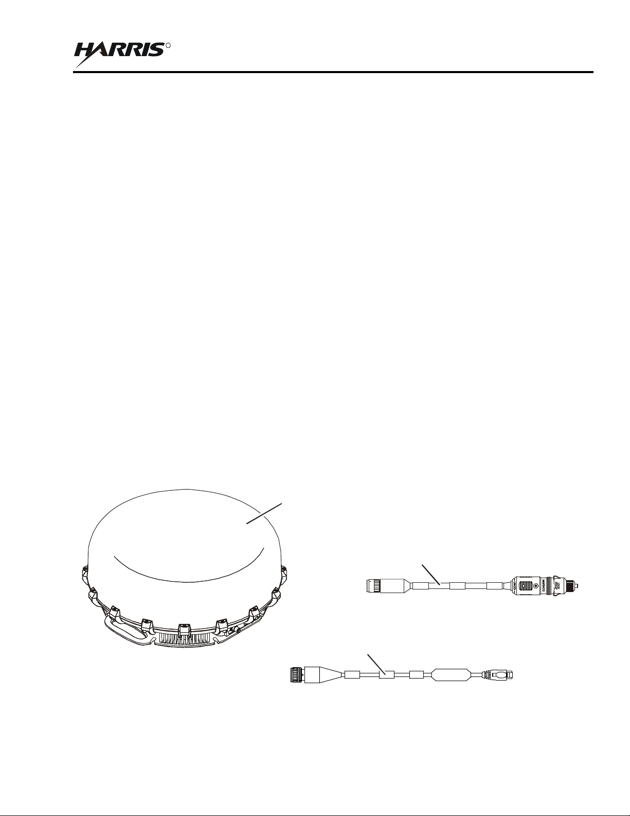
12 VDC CABLE ASSEMBLY
(12043-0843-A015)
BGAN - ETHERNET
CABLE ASSEMBLY
(12043-0833-A010)
SYSTEM SETUP AND TEARDOWN
CHAPTER 2
SYSTEM SETUP AND TEARDOWN
2.1 ITEMS INCLUDED WITH RF-7800B BGAN TERMINAL
The standard items included with the Broadband Global Area Network (BGAN) terminals are described below.
Refer to Paragraph 1.9 for optional accessories.
RF-7800B-VU104 Land Mobile BGAN Terminal includes the following. See Figure 2-1.
12043-0833-A010 BGAN to Ethernet Cable, 10 feet
12043-0843-A015 Automobile 12 VDC Power Cable, 15 feet
12091-0040-10 BGAN Terminal, Class 10 Land Mobile, Tan
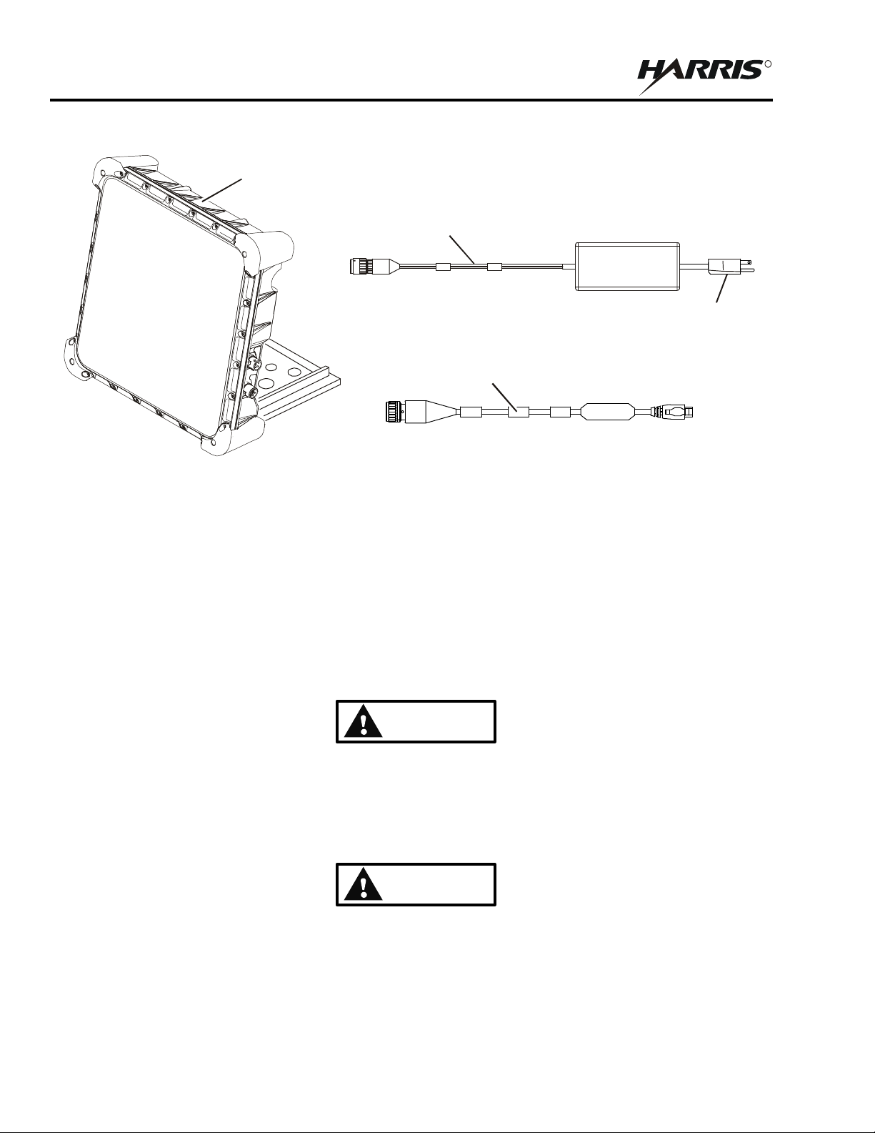
RF-7800B-DU024 Land Portable BGAN Terminal includes the following. See Figure 2-2.
12043-0833-A010 BGAN to Ethernet Cable, 10 feet
12043-0844-A1 AC to DC Power Supply (includes international plug adaptor kit). Refer to Paragraph 2.5.3.
12091-0020-10 BGAN Terminal, Class 2 Land Portable, Tan
For BGAN network access, contact your service provider for
a Universal Mobile Telecommunications System (UMTS)
Subscriber Identification Module (SIM) (USIM) and its
Personal Identification Number (PIN), and Satellite Terminal
configuration instructions.
LAND MOBILE
BGAN TERMINAL
(12091-0040-10)
BGAN - DC POWER TO VEHICLE
CL-0365-4200-0004
Figure 2-1. Items Included with RF-7800B-VU104
2-1
RF-7800B
R
WARNING
WARNING
BGAN - AC TO DC POWER
SUPPLY ASSEMBLY
(12043-0844-A1)
ADAPTORS
NOT SHOWN
CABLE ASSEMBLY
BGAN TERMINAL
(12091-0020-10)
SYSTEM SETUP AND TEARDOWN
LAND PORTABLE
BGAN - ETHERNET
(12043-0833-A010)
CL-0365-4200-0005
Figure 2-2. Items Included with RF-7800B-DU024
2.2 INSTALLATION GUIDELINES
The information contained here provides general guidelines for installing the BGAN terminal. Read this chapter in
its entirety before beginning installation.
2.2.1 Environmental
The BGAN terminal will perform in the environment specified in Table 1-1.
Do not operate the BGAN terminal during electrical storms.
Disconnect the terminal from the computer and radio and store
the unit indoors if lightening is anticipated in the area of
operation. Electrocution may result in severe personal injury
or death.
Never use the BGAN terminal where blasting work is in
progress. Observe all restrictions and follow any regulations
or rules. Do not use the terminal while at a fuel filling station,
do not use near fuel or chemicals. areas with potentially
explosive environments are often, but not always, clearly
marked.
2-2

RF-7800B
R
CAUTION
SYSTEM SETUP AND TEARDOWN
Avoid placing BGAN terminal near any source of heat such as
an open flame or cigarettes.
2.2.2 Dimension and Weight Information
Refer to Table 1-1 for the dimensions and weights.
2.2.3 Power Requirements
Refer to Table 1-1 for power requirements. Refer to Paragraph 1.9 for the various optional power cables available.
2.2.4 Grounding
Neither the RF-7800B-VU104 or RF-7800B-DU024 require mounting on a ground plane for performance.
2.3 UNPACKING AND REPACKING
Equipment is packed in corrugated boxes. A two-piece foam enclosure protects the equipment against corrosion and
rough handling. Boxes and packing materials should be retained in case the equipment is reshipped.
2.3.1 Unpacking
Perform the following procedure to unpack the BGAN terminal:
a. Inspect the exterior of the box for signs of damage during shipment. Document any problems and report
them to the proper authority.
b. Move the boxed equipment to the general location where it is to be installed.
c. After removing the equipment, check the contents against the packing slip to see that the shipment is
complete. Report discrepancies to Harris/RF Communications Product Service Department
(telephone: 585-244-5830, toll free: 866-264-8040, web: https://premier.harris.com/rfcomm).
2.3.2 Repacking
Perform the following procedure to repack the BGAN terminal:
a. Use the original box, if it was retained. If not, use a box that allows at least three inches of clearance on
all sides of the BGAN terminal components.
b. Use the original packing material, if it was retained. If not, use foam packing material to fill the space
between the BGAN terminal components and the box. Surround the entire unit with several inches of
foam packing material.
c. Use a good quality packing tape (or straps) to seal the box after closing.
2.4 BGAN TERMINAL SETUP
After receiving the USIM card from your BGAN service provider, install the card into the BGAN terminal.
2-3
RF-7800B
R
NOTE
CAUTION
HOLDER
SYSTEM SETUP AND TEARDOWN
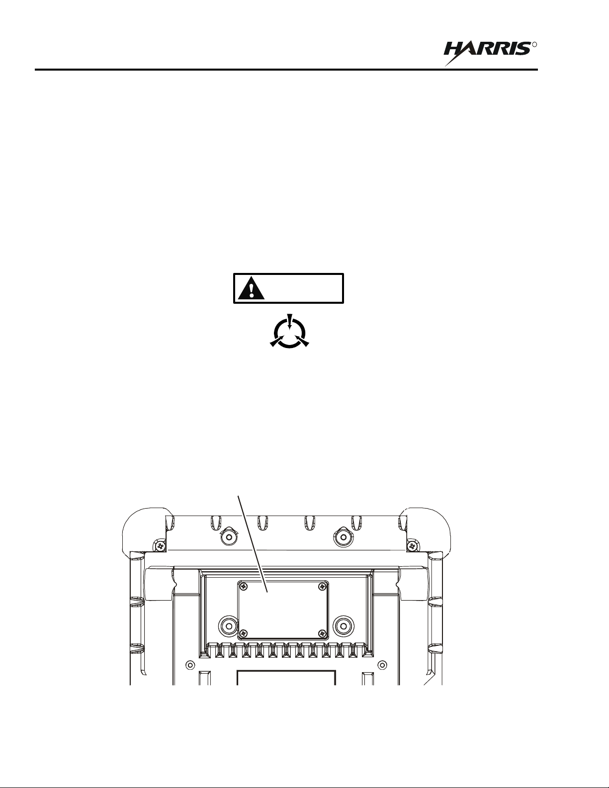
2.4.1 Installing USIM in RF-7800B-DU024
Perform the following procedure to install the USIM/SIM in RF-7800B-DU024:
a. Position the BGAN terminal so that the bottom surface is facing you.
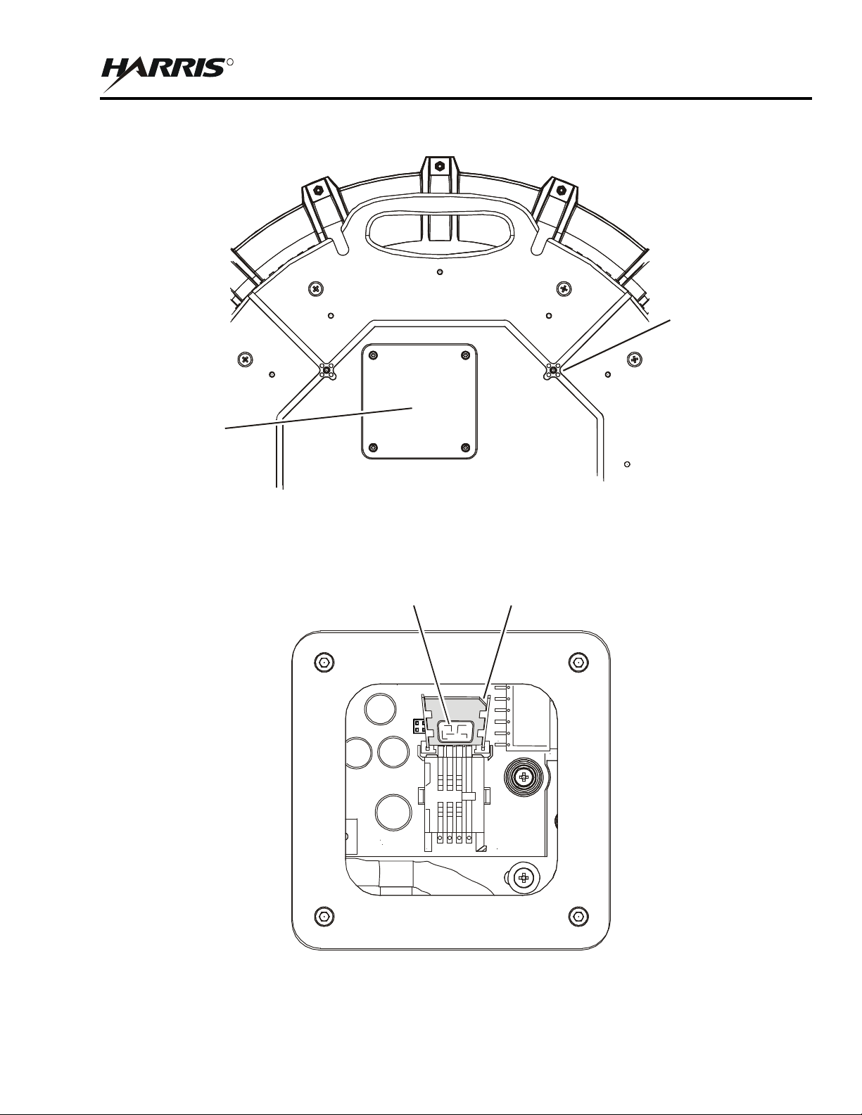
b. Remove the four screws and the USIM plate to access the USIM card holder. See Figure 2-3.
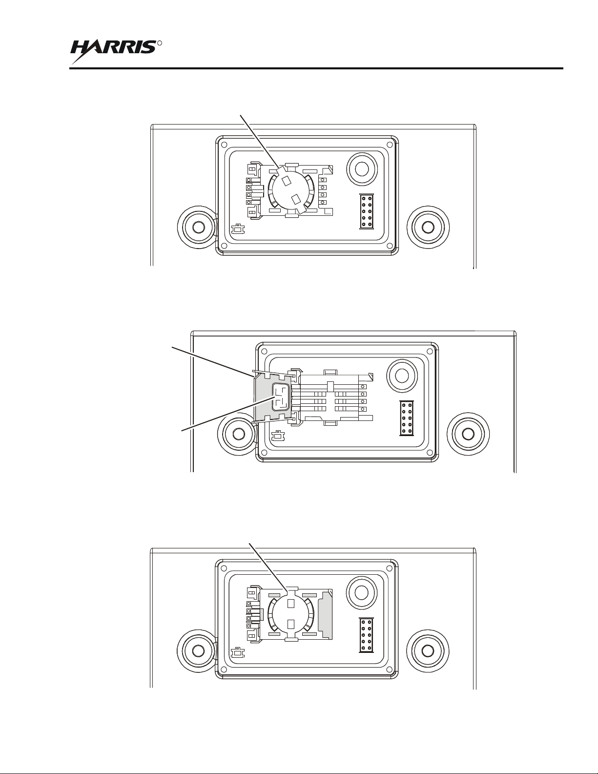
c. Put your index finger on the USIM holder and rotate counterclockwise to open. See Figure 2-4.
d. Lift the USIM card holder up in order to place the USIM card in the holder. See Figure 2-5.
Do not bend or damage the USIM/SIM. Damaged contacts
may cause the card not to work.
USIM cards are sensitive to electrostatic discharges.
e. Install the USIM card in the card holder making sure the gold contacts are facing down. The angled part
of the USIM is in the upper right-hand corner. See Figure 2-5.
f. With the card in place, push the holder down and with your index finger, rotate the locking mechanism
clockwise to lock card in place. See Figure 2-6.
g. Put the USIM plate back on and tighten the four screws. See Figure 2-3.
USIM CARD
CL-0365-4200-0006
Figure 2-3. Accessing the USIM Card Holder on RF-7800B-DU024
2-4
SYSTEM SETUP AND TEARDOWN
R
ANGLED EDGE
GOLD CONTACTS
ON THIS SIDE
UNLOCKED POSITION
CL-0365-4200-0007
Figure 2-4. Opening the USIM Card Holder on RF-7800B-DU024
RF-7800B
OF USIM CARD
CL-0365-4200-0008
Figure 2-5. Placing the USIM Card in Holder on RF-7800B-DU024
LOCKED POSITION
CL-0365-4200-0009
Figure 2-6. USIM Card Located in Holder on RF-7800B-DU024
2-5

RF-7800B
R
NOTE
CAUTION
SYSTEM SETUP AND TEARDOWN
2.4.2 Installing USIM in RF-7800B-VU104
Perform the following procedure to install the USIM/SIM in the RF-7800B-VU104:
a. Position the BGAN terminal with the topside down onto a smooth/soft surface to prevent scratching the
radome and with the bottom surface facing you.
b. Remove the four screws and the USIM plate to access the USIM card holder. See Figure 2-7.
c. Put your index finger on the USIM holder and rotate counterclockwise to open.
d. Lift the USIM card holder up in order to place the USIM card in the holder. See Figure 2-8.
Do not bend or damage the USIM/SIM. Damaged contacts
may cause the card not to work.
USIM cards are sensitive to electrostatic discharges.
e. Install the USIM card in the card holder making sure the gold contacts are facing down. The angled part
of the USIM is in the upper right-hand corner. See Figure 2-8.
f. With the card in place, push the holder down and with your index finger, rotate the locking mechanism
clockwise to lock card in place.
g. Put the USIM plate back on and tighten the four screws. See Figure 2-7.
2-6
RF-7800B
R
USIM CARD
HOLDER
A
ON THIS SIDE
SYSTEM SETUP AND TEARDOWN
DRAIN HOLE
(4 PLACES)
CL-0365-4200-0010
Figure 2-7. Accessing the USIM Card Holder and Drain Holes on RF-7800B-VU104
GOLD CONTACTS
NGLED EDGE
OF USIM CARD
CL-0365-4200-0012
Figure 2-8. Placing the USIM Card in Holder on RF-7800B-VU104
2-7

RF-7800B
R
SYSTEM SETUP AND TEARDOWN
2.5 INSTALLATION PROCEDURES
The paragraphs that follow describe the installation of an BGAN terminal.
2.5.1 RF-7800B-VU104 Installation
RF-7800B-VU104 is intended for installation onto a vehicle roof. Some installation hardware may need to be
installer furnished. Tools and installation materials will vary for each application.
a. The four drain holes on the bottom of the RF-7800B-VU104 are shipped in the open position. See
Figure 2-7. This allows any moisture from condensation to drain out. If the operational conditions
require that these be closed, periodic maintenance to open these and drain any moisture will be required.
Refer to Paragraph 5.1.
b. If using a magnetic mount, place BGAN terminal on roof of vehicle. Make sure the area is clear before
mounting the antenna using the magnetic mounts. If the mounting area is dirty or covered with snow or
ice, the strength of the magnetic mounts may be compromised.
c. If mounting the BGAN terminal on a flat surface using 0.213 - 0.312 inch bolts with 5/16-inch hole
stainless steel flat washers, and 5/6-inch nut, do the following:
1. Make hole pattern template from RF-7800B-VU104 mounting holes.
2. Place template on flat mounting surface and drill holes.
3. Mount RF-7800B-VU104 using 0.213 - 0.312 inch bolts with 5/16-inch hole stainless steel flat
washers, and 5/6-inch nut.
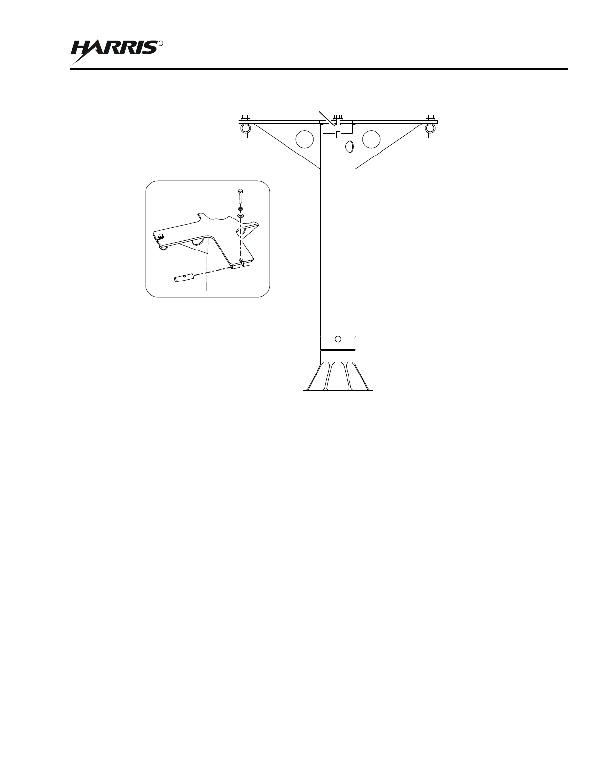
d. If mounting the BGAN terminal using a pole mount mast assembly, do the following:
1. Mount the base of the pole mount on a standard 4-bolt antenna base which can support up to 50
pounds (22.68 kg). See Figure 2-9.
2. Mount the BGAN terminal to the pole mount mast.
e. Make data and power connections. Refer to Paragraph 2.5.3.
2-8
R
DETAIL
(4 PLACES)
SEE DETAIL
RF-7800B
SYSTEM SETUP AND TEARDOWN
CL-0365-4200-0011
Figure 2-9. Pole Mount Option
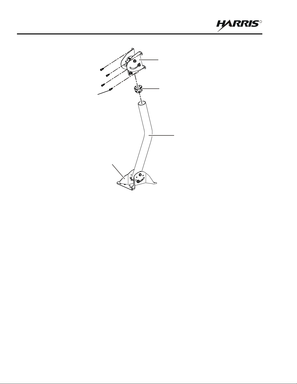
2.5.2 RF-7800B-DU024 Fixed/Semi-fixed Installation
The Land Portable BGAN Terminal can be mounted on a pole or flat surface (such as a wall or roof) using the Fixed
Mount Kit, 12091-4150-01. See Figure 2-10. This kit includes a universal pole mount, incline bracket, bubble level
indicator and holder, pole ground cable, and four terminal mounting screws. Items required to mount the universal
pole mount to a structure are customer furnished. Proper installation ensures that the BGAN terminal is always
correctly pointed at the satellite. The BGAN terminal can then be left alone for an extended period of time without
having to be re-pointed or set-up. The fixed mount kit accessory can be re-used to install the BGAN terminal in
different locations.
When mounted in a location where access to the BGAN terminal may not be straightforward (for example, mounted
high on a wall), set the BGAN terminal to recover automatically after a power outage. To permit this fixed
installation, modify the following BGAN terminal properties using the embedded Web interface. See Figure 4-2.
Auto Power On mode is enabled
Bypass Antenna Pointing is enabled
The following items are found in the Fixed Mount Kit, 12091-4150-01. Mount to a suitable surface.
Fixed Mount Screws
Mounting bracket and shaft
Level
Grounding strap
2-9
RF-7800B
R
NOTE
MOUNT
AND HOLDER
SCREW, CAP,
HEX SOCKET,
1/4 - 20X1/2
(4 PLACES)
NOTE: USE CUSTOMER FURNISHED
MOUNTING HARDWARE FOR POLE
OR SURFACE MOUNT.
A
BRACKET ASSEMBLY
SYSTEM SETUP AND TEARDOWN
ZIMUTH CANISTER/INCLINE
BUBBLE LEVEL INDICATOR
UNIVERSAL
CL-0365-4200-0013
Figure 2-10. Fixed Mount Option
2.5.3 Cable Connections
For connector pinouts, refer to Paragraph A.1. See Figure 2-11 for some installation options. Refer to Paragraph 3.3
for detailed connection information. In general, install the following:
Data cable between BGAN terminal and computer
Power cable between BGAN terminal and power source. For the RF-7800B-DU024 using the BGAN, AC
to DC Power Supply Assembly with plug kit, use one of the following plugs:
ST-5: United States, Canada, Japan, China, Taiwan
ST-7: United Kingdom, Hong Kong, Singapore
ST-9: Germany, France, Indonesia, Korea
ST-16: Australia, New Zealand, China
ST-9C: European Union, United Arab Emirates, South America
Do not use excessive force when connecting the data and
power cables to the BGAN terminal. Connectors are keyed.
2-10
 Loading...