

Page 1
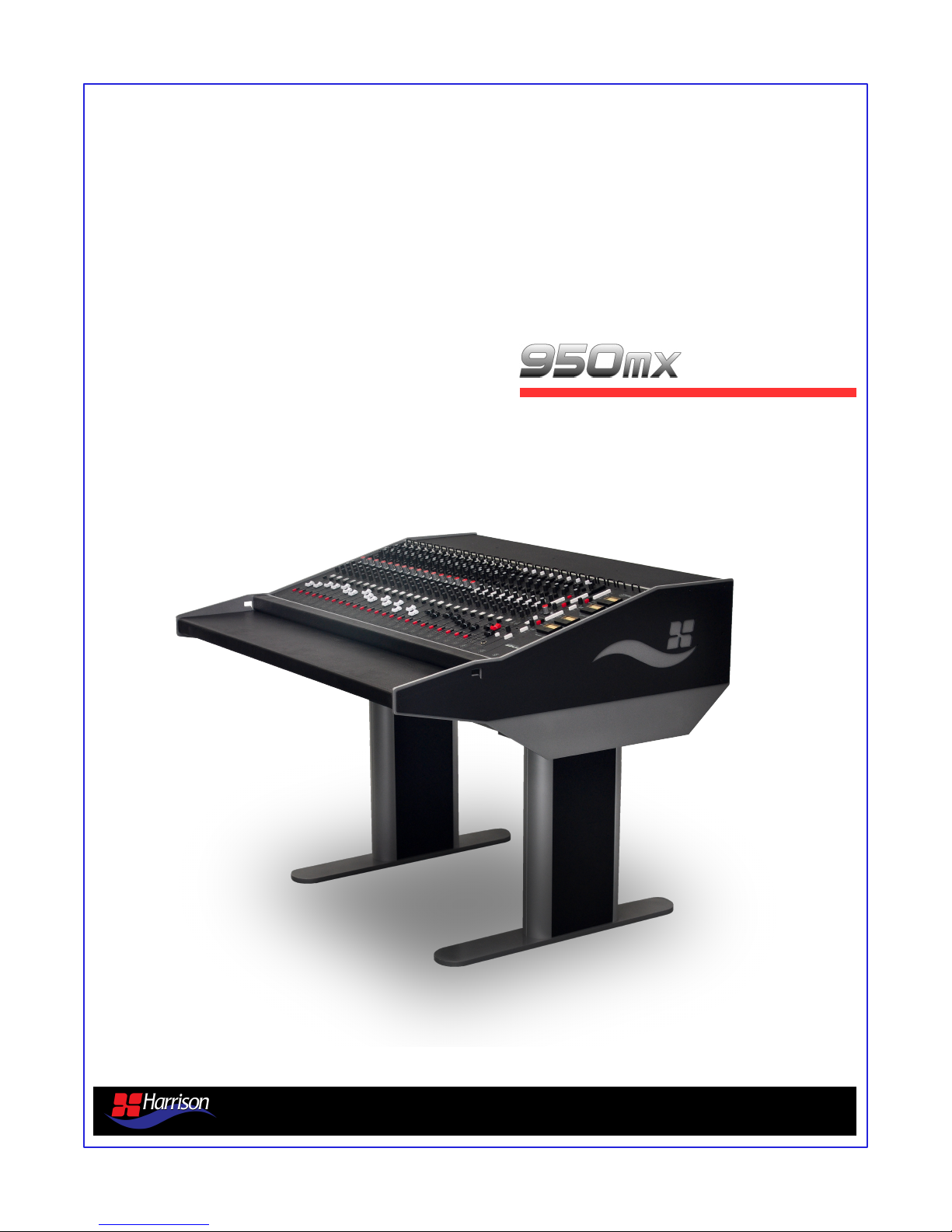
analog console overview
v1.5 January 2014
Page 2

Table of Contents
Section Heading Page
-- Copyright Information 2
1.0 Introduction 3
2.0 Standard Configurations 4
3.0 Block Diagram 7
4.0 Mono Mic/Line Module 8
5.0 Stereo Line Module 9
6.0 Dual Mix Bus Master Module 10
7.0 Control Room Monitor Module 11
8.0 Dual Alternate Output Module 12
9.0 Rear Panel Connections 13
10.0 Specifications 14
11.0 Power Supply Specifications 15
12.0 Environmental Specifications 17
13.0 Module Jumper Settings 18
14.0 Harrison Contact Information 19
Harrison Consoles Copyright Information 2013
No part of this publication may be copied, reproduced, transmitted, stored on a retrieval system, or translated
into any language, in any form or by any means without the prior written consent of an authorized officer of
Harrison Consoles, 1024 Firestone Parkway, La Vergne, TN 37086.
Disclaimer
Harrison Consoles makes no representations or warranties whatsoever with respect to the content of this
document and specifically disclaims any implied warranties of merchantability or fitness for any particular
purpose. We reserve the right to make alterations as technical progress may warrant at the discretion of
Harrison Consoles. Harrison Consoles has no obligation to notify any person or entity of any changes and/or
revisions to this publication. We reserve the right to change materials and specifications without notice.
Proprietary Information
The information contained in this document is the property of Harrison Consoles. and is proprietary to and a
trade secret of Harrison Consoles. This document and the information contained herein and derived therefrom
are not to be disclosed to any person without the express written consent of an duly authorized officer of
Harrison Consoles.
950mx analog console overview v1.5 Page 2
Page 3

1.0 Introduction
The heart of analog - with a modern aesthetic - built with today’s music studio in mind
Analog Mixing - The 950mx sports a history rich analog design incorporating the same high-end modular
design elements found across the spectrum of Harrison console models from eras past such as the 32
Series, MR Series, S10, S12 and LPC. The 950mx provides a superior analog “mixing” platform designed
specifically to complement today’s high performance music studio where powerful DAW’s and high-end
specialized outboard gear are plentiful.
High Performance Design - The 950mx incorporates key high quality design criteria. Double sided
PCB’s, manual PCB layout techniques providing specific trace placement and robust ground plane design,
linear power distribution, gold Euro-card module connectors, gold plated switches, conductive plastic
potentiometers, 100% through-hole design (no surface mount components) and summing busses carried
via PCB’s (no ribbon cable summing busses) all combine to provide the highest performance possible in
analog console design.
Dual Stereo Mix Bus Design – The 950mx provides two distinctly different and independent mix bus
choices. Each channel can route to either or both of the stereo mix busses. The “RED” bus or Mix Bus 1
(indicated by the red assignment switch on each channel and the red master fader in the master section)
provides a transformer balanced stereo output stage reminiscent of Harrison’s vintage console models (32
Series and early MR Series). The “BLACK” bus or Mix Bus 2 (indicated by the black bus assignment
switch on each channel and the black master fader in the master section) provides an electronically
balanced stereo output stage reminiscent of Harrison’s more recent analog console models (S10, S12 and
LPC).
Mono Mic/Line Channels – 4 Mono Mic/Line Channels are also included in each standard configuration
(custom configurations available upon request) offering a high performance Harrison mic preamplifier, 3
band variable EQ with variable HP and LP filters, with design characteristics found in the S10, S12 and
LPC consoles along with a switchable Line input and balanced insert point ready for your favorite
outboard preamp or other processing gear and a direct output for recording.
Stereo Channels – Unlike traditional analog music console designs the Harrison 950mx provides Stereo
Input Channels as standard equipment.
These precision designed stereo channels are ideally suited for use with today’s typical ‘stereo stem’ track
layout preference of DAW power users. An ample supply of stereo channels in each standard
configuration allows many more tracks to be more efficiently mixed using a smaller more cost effective
console footprint.
DAW Compatible Frame Design – The 950mx frame design is rugged and unique. It is specifically
designed to solve some of the more basic yet troubling ergonomic issues in today’s studio environment.
“Where do I put my keyboard and mouse or trackball?” and “Where do I put my computer monitor/s?” The
950mx solves those issues by providing a 2-tiered front bolster which is wide and deep enough to
comfortably locate your DAW keyboard and mouse/trackball (with sufficient cable access) along with a
generous ‘flat’ top ideal for locating DAW monitor/s and/or small speakers etc. depending on frame size.
Configurations – The 950mx is available in 3 standard configurations featuring 12 channels (4 Mono, 8
Stereo), 16 channels (4 Mono, 12 Stereo) and 24 Channels (4 Mono, 20 Stereo) options. Custom
configurations are available upon request.
Summary – The 950mx is a true ‘blast-from-the-past’ but made for today’s top-end music studios. With its
premium analog circuit designs based on 35 years of expertise, specific ‘DAW friendly’ design criteria and
rugged modular construction, this console is built to last. By focusing on specific analog mixing
requirements of today’s music studio environment Harrison can offer a powerful, high-quality solution at
an affordable price.
950mx analog console overview v1.5 Page 3
Page 4

2.0 Configurations
16 Channel Example (8 mono / 4 stereo) – 32.1”
12 Channel Example (8 mono / 4 stereo) – 26.4”
950mx analog console overview v1.5 Page 4
Page 5
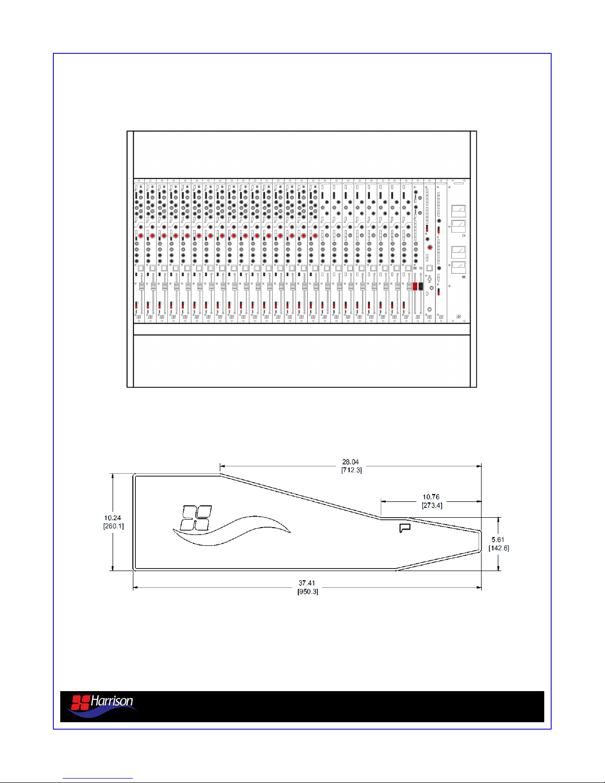
2.0 Configurations
24 Channel Configuration (16 mono / 8 stereo) – 43.4”
950mx analog console overview v1.5 Page 5
Page 6
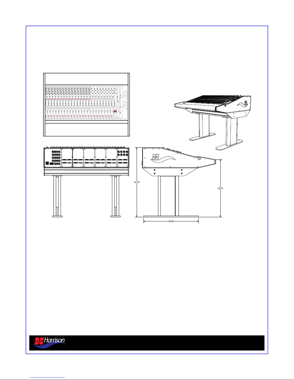
2.0 Configurations
24 Channel Configuration (16 mono / 8 stereo) – 43.4 Shown with optional floor standing frame.
950mx analog console overview v1.5 Page 6
Page 7
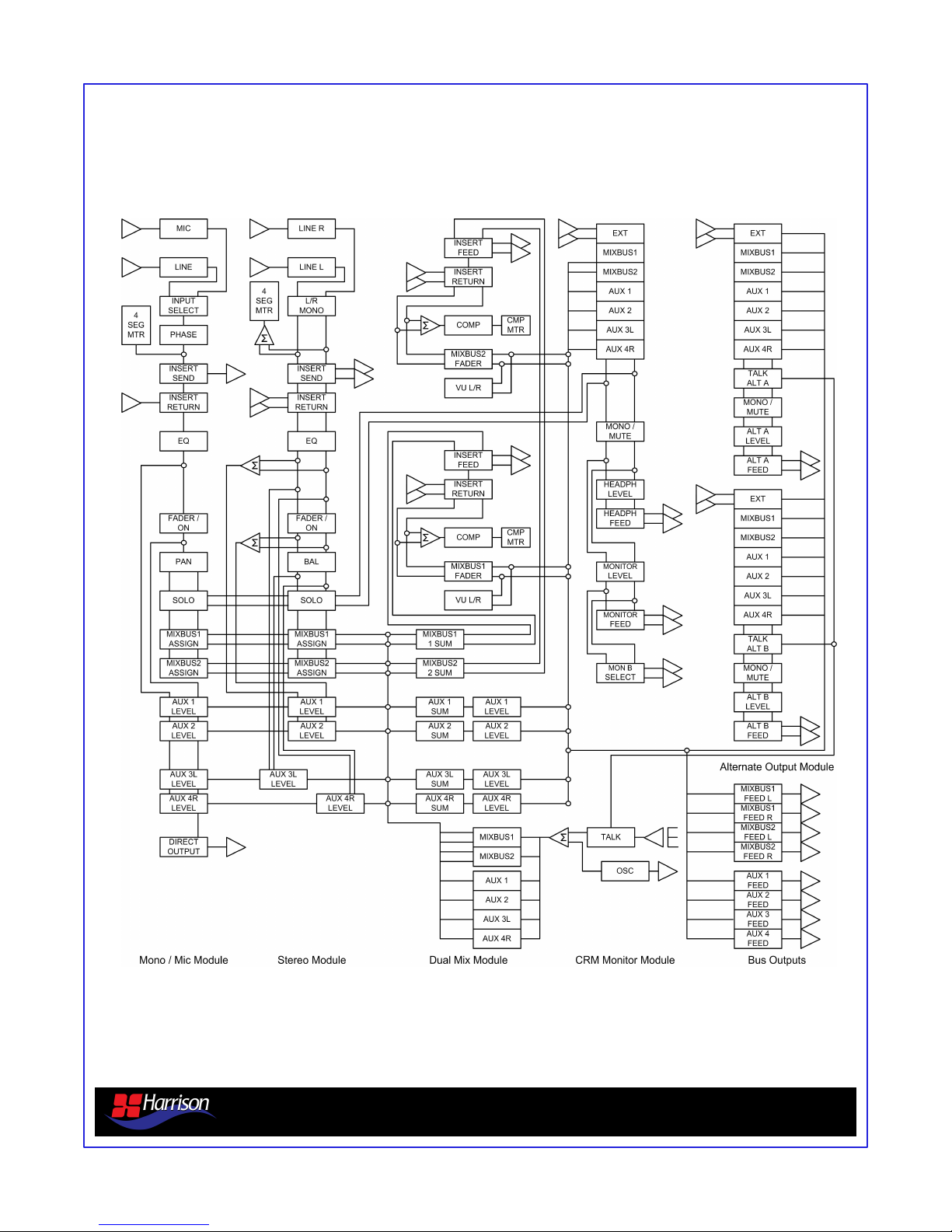
3.0 Block Diagram
950mx analog console overview v1.5 Page 7
Page 8
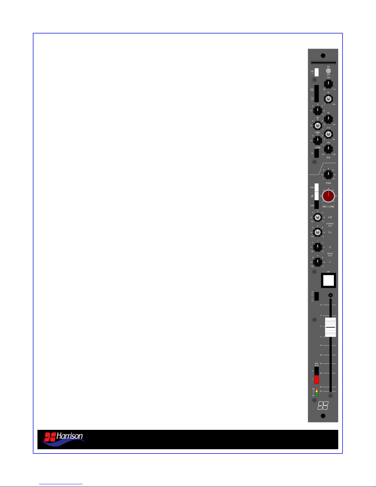
4.0 Mono Mic / Line Module
Insert Point - Line-level insertion point for an external device. The Insert is always driven and is
pre fader and tone controls. A separate post Fader and Tone controls, line level direct output is
provided on each Mono Mic / Line module.
Phantom Power - +48 volts DC for microphones that require phantom power.
Filters - Variable HP (24Hz-1.1kHz 12dB per octave), variable LP Filter (20kHz-700hz 12dB per
octave). The filters are not affected by the EQ IN switch.
EQ Controls - HIGH band (+-15dB variable 800Hz-14kHz), MID band (+-15dB variable 400Hz8kHz), LO band (+-15dB variable 40Hz-1.8kHz) the IN switch inserts the EQ into the signal path.
The EQ IN switch does not affect the HP and LP Filters.
Pan Control - Deviates the mono signal to the left and right mix busses. Unity gain at center, fully
panned to the left or right gives +3dB.
Input Select - Gain / Level knob controls the Mic gain. W hen LINE is selected the line level input
is selected and feed to the channel at unity gain. When LINE is not selected the Mic Preamplifier
input is selected and the gain is from 0dB (level down, 20dB PAD inserted) to 70dB (level up, 20dB
PAD not inserted). Polarity reverse is provided and affects either the Mic or Line input.
Auxiliary Sends - Aux level control for mono sends 1-2 and for stereo send Aux 3L and 4R.
Jumper options are available on the module for pre or post fader settings. The level control has a
range from mute to unity gain.
Channel ON - Enables the channel VCA. The LED switch is illuminated when the channel is ON.
SOLO - The solo signal is derived after the fader. Selecting SOLO assigns the channel to the solo
bus. To listen to the solo bus the SOLO switch must be selected on the Control Room Monitor
module.
Mono Fader - The 100mm linear travel fader carrying DC control voltage is used to vary the main
signal level from mute to +12dB.
Stereo Mix Bus Routing - Stereo Mix Bus routing switches 1 and 2 send post fader and pan
switches to either or both stereo mix busses provided. The “RED” bus (1) provides a transformer
balanced output stage while the “BLACK” bus (2) provides an electronically balanced output stage.
Input Meter - The four segment input meter is directly after the input section pre EQ and fader.
Direct Out - The direct out is line level signal that is post EQ, filters, and fader.
950mx analog console overview v1.4 Page 8
Page 9
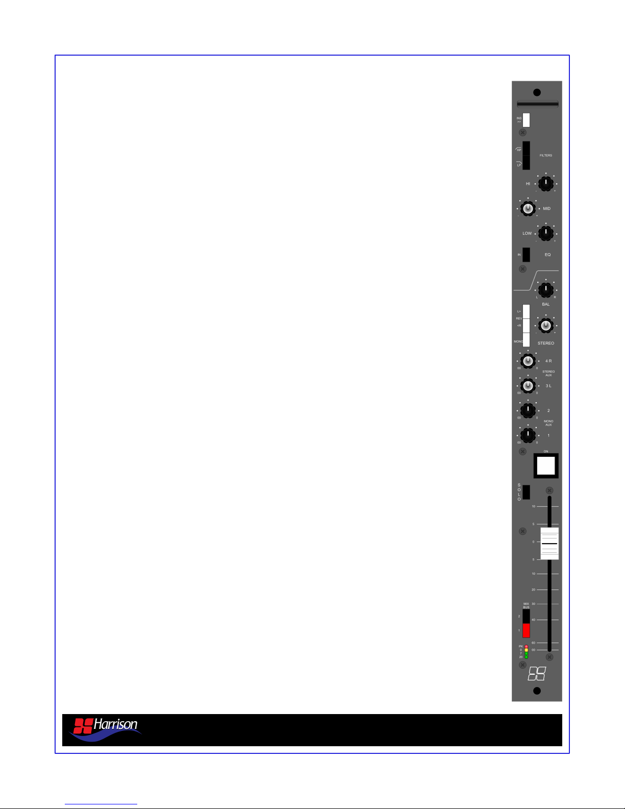
5.0 Stereo Line Module
Insert Point - Line-level insertion point for an external device. The Insert is always driven and is
pre fader and tone controls.
Filters - HP Filter (100Hz - 12dB/Octave), LP Filter (10kHz - 12dB/Octave)
The filters are not affected by the TONE IN switch.
EQ Controls - HIGH (+ -15dB - 10kHz center), MID (+ - 15dB - 4kHz center), LOW (+ - 15dB 100Hz center). The IN switch inserts the TONE controls into the signal path. The EQ IN switch
does not affect the HP and LP filters.
Balance Control - Deviates the stereo signal to the left and right mix busses. Unity gain at center,
fully positioned to the left or right gives +3dB.
Stereo Input Section - Level knob controls the stereo line input trim from + - 10dB. L > places the
left input to both the left and right sides of the stereo channel. < R places the right signal on both
the left and right sides of the stereo channel. LR together reverses the left and right inputs to the
stereo channel. MONO combines the left and right signals to both sides of the stereo signal.
Auxiliary Sends - Aux level control for mono sends 1-2 and for stereo send Aux 3L and 4R.
Jumper options are available on the module for pre or post fader settings. The level control has a
range from mute to unity gain.
Channel ON - Enables the channel VCA. The LED switch is illuminated when the channel is ON.
SOLO - The solo signal is derived after the fader. Selecting SOLO assigns the channel to the solo
bus. To listen to the solo bus the SOLO switch must be selected on the Control Room Monitor
module.
Stereo Fader - The 104mm linear travel fader carrying DC control voltage is used to vary the main
signal level from mute to +12dB.
Stereo Mix Bus Routing - Stereo Mix Bus routing switches 1 and 2 send post fader and pan
switches to either or both stereo mix busses provided. The “RED” bus (1) provides a transformer
balanced output stage while the “BLACK” bus (2) provides an electronically balanced output stage.
Input Meter - The four segment input meter is directly after the input section pre EQ and fader and
is a sum of the left and right inputs.
950mx analog console overview v1.5 Page 9
Page 10
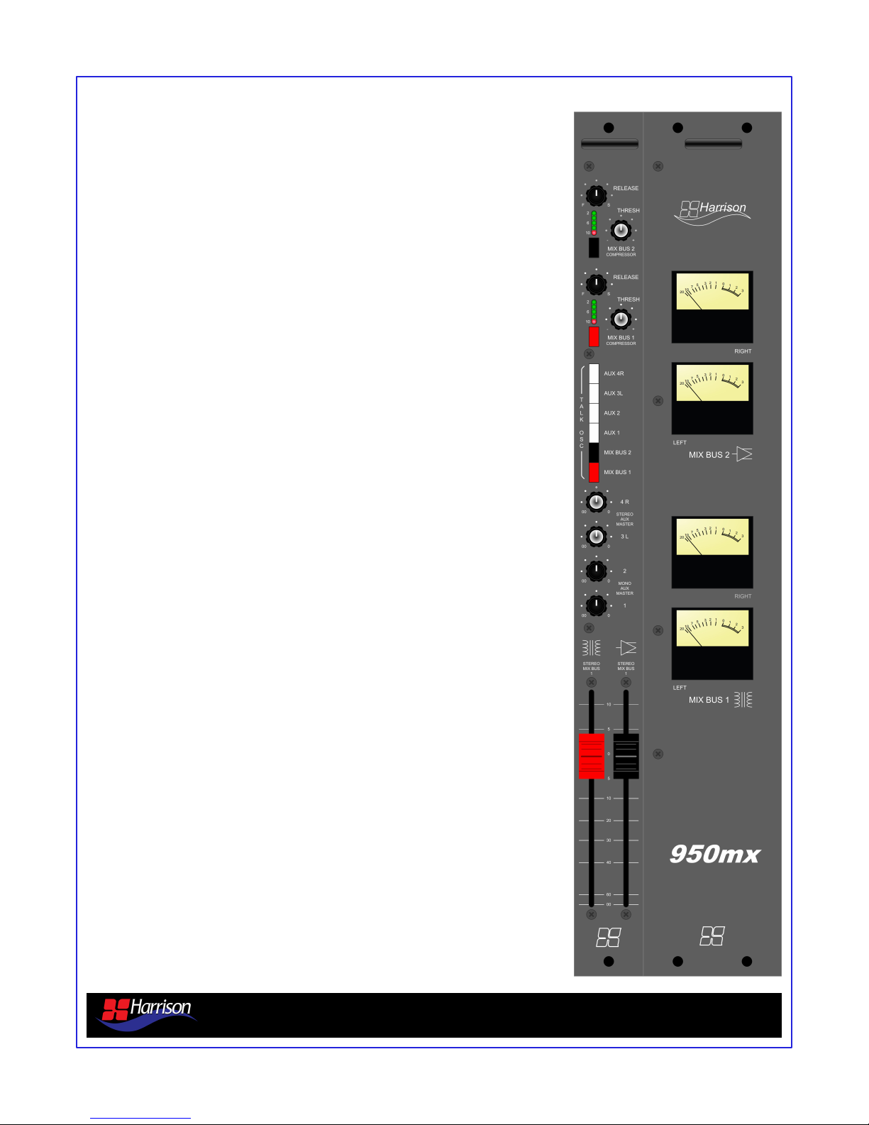
6.0 Mix Bus Master Module
Mix Bus Compressors
Two Mix Bus compressor sections are provided one for each of the
stereo mix busses. Compressor controls include: Variable Release Time
(.1ms - 4s), Variable Threshold (-15dB - +15dB), ON switch which
places the compressor in and out of circuit and a gain reduction LED
meter. The compressor Ratio is set at 2:1 with an Attack Time of .1ms.
Oscillator / Talk Assignment
The Oscillator and/or the Talkback Microphone can be sent to the
console busses Aux 1-4 and the 2 Mix Busses by selecting the
appropriate switch. When the switches are selected the Oscillator and/or
the Talkback Mic will feed the selected busses upon activation.
Auxiliary Master Level Controls
Aux master level controls for mono sends 1-2 and for stereo send Aux
3L and 4R. Jumper options are available on each input module for pre
or post fader settings. The level control knob has a range from mute to
unity gain.
Mix Bus Pointer Meters
Pointer VU meters for both the “RED” and “BLACK” Mix Bus outputs are
located at the far right end of the console.
Mix Bus Output Faders
104mm faders for each of the stereo mix bus outputs. “RED” bus
(Stereo Mix Bus 1) output provides a transformer balanced output stage
while the “BLACK” bus (Stereo Mix Bus 2) output provides an
electronically balanced output stage.
Mix Bus Insert Point
Each of the two stereo mix bus outputs has a corresponding balanced
insert point that can be jumper selected as “always inserted” on either or
both stereo mix bus outputs. This insert point allows for an insertion of
external processing directly on either of the two mix bus outputs. No
front panel controls are provided for the mix bus insert points.
Common practice is to enable the jumper and “normal” the insert point
at a patch bay.
950mx analog console overview v1.5 Page 10
Page 11
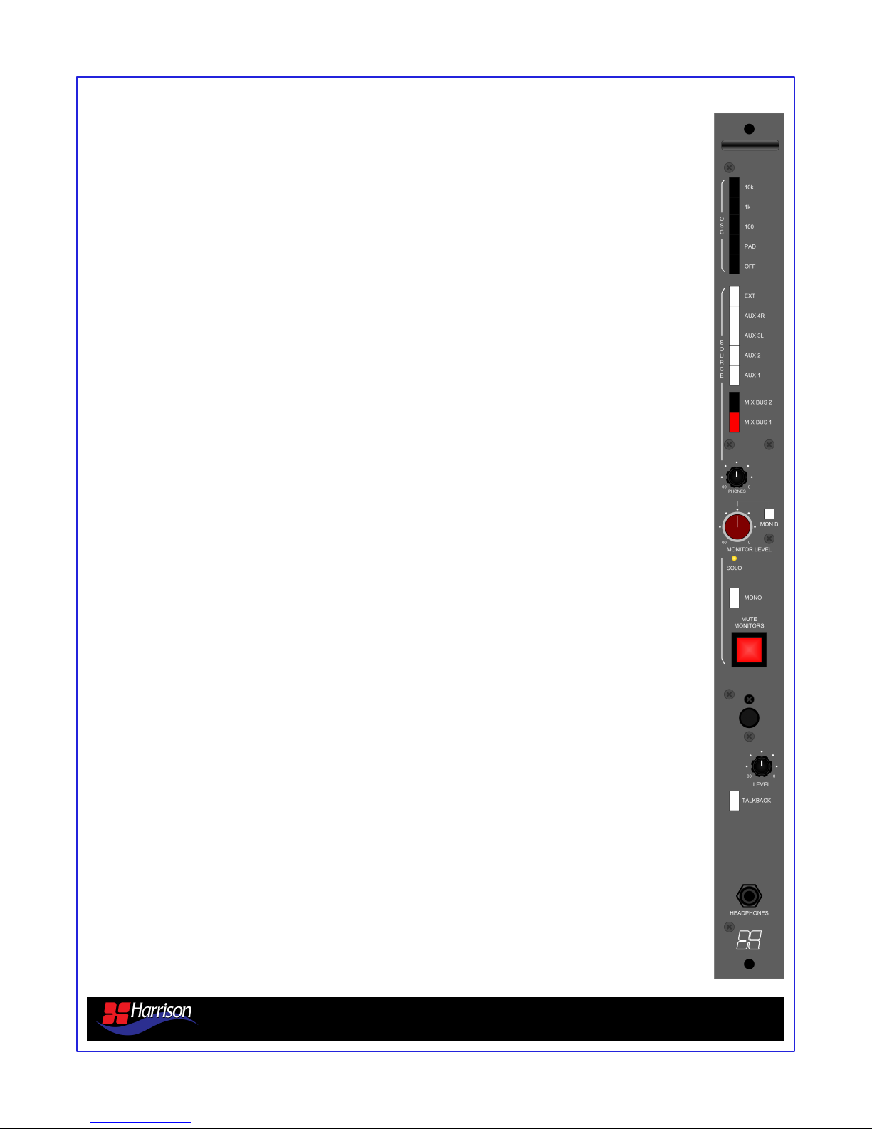
7.0 Control Room Monitor Module
Oscillator
The tone Oscillator provides 100hz, 1kHz and 10kHz sine-waves by selecting the appropriate
switch. The oscillator level is +4dBu. A fixed -20dB PAD switch is provided. The Oscillator has a
separate XLR output on the console rear and also can be assigned to any of the console bus
outputs.
Monitor Sources
Monitor source selection for the Main control room speakers and the Headphone output are
Mix Bus 1, Mix Bus 2, Aux 1-2 and for stereo send Aux 3L and 4R and an External input
provided via XLR connectors on the console rear.
Headphone Level Control
Controls the Headphone output level from mute to unity gain.
Main Speaker Controls
The MONITOR LEVEL knob controls the main speaker output level from mute to unity gain. It
also controls the level to the B monitor output via the MON B switch for use with a near-field or
secondary set of control room speakers. When an input channel has SOLO selected the yellow
LED lights on the Control Room Monitor module indicating there is a solo active on the
console. MONO combines the left and right monitor sources and MUTE mutes the Main
speakers and the Headphones.
Talkback Section
Talkback Mic level knob controls the level of the condenser microphone provided. The TALK
switch enables talkback to the assigned outputs on the Dual Mix Bus master module.
1/4” Headphone Jack
The headphone output shares the source, mono/stereo, mute, and solo settings of the Main
Speakers.
950mx analog console overview v1.5 Page 11
Page 12
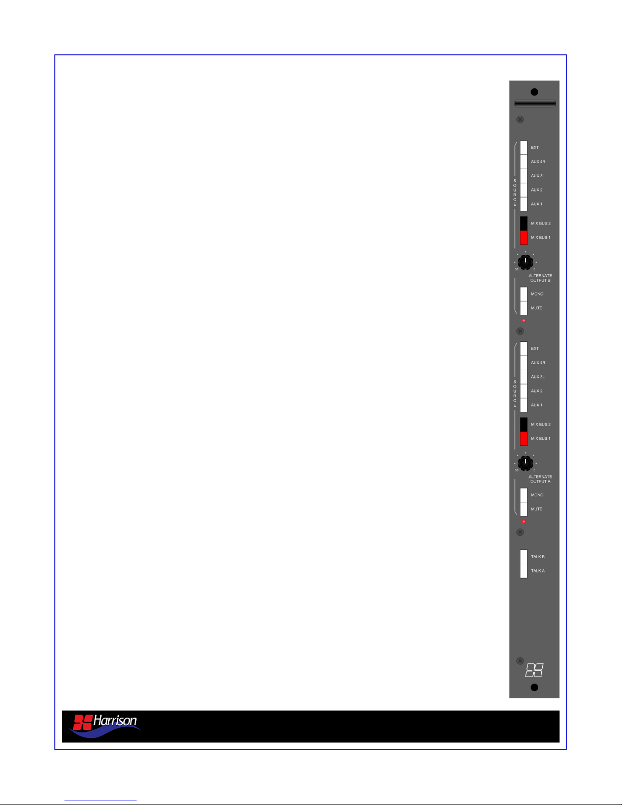
8.0 Dual Alternate Output Module
Alternate Output B Source Selections
Monitor source selection for the Alternate Output B output are Mix Bus 1, Mix Bus 2, Aux 1-4
and an External input provided via XLR connectors on the console rear.
Alternate Output B Controls
The Alternate Output B level knob controls the Alternate Output B output level from mute to
unity gain. MONO combines the left and right monitor sources and MUTE mutes the Alternate
Output B output.
Alternate Output A Source Selections
Monitor source selection for the Alternate Output A output are Mix Bus 1, Mix Bus 2, Aux 1-4
and an External input provided via XLR connectors on the console rear.
Alternate Output A Controls
The Alternate Output A level knob controls the Alternate Output A output level from mute to
unity gain. MONO combines the left and right monitor sources and MUTE mutes the Alternate
Output A output.
Talkback Section
Allows direct talk back to either Alternate Output A or Alternate Output B outputs.
950mx analog console overview v1.5 Page 12
Page 13
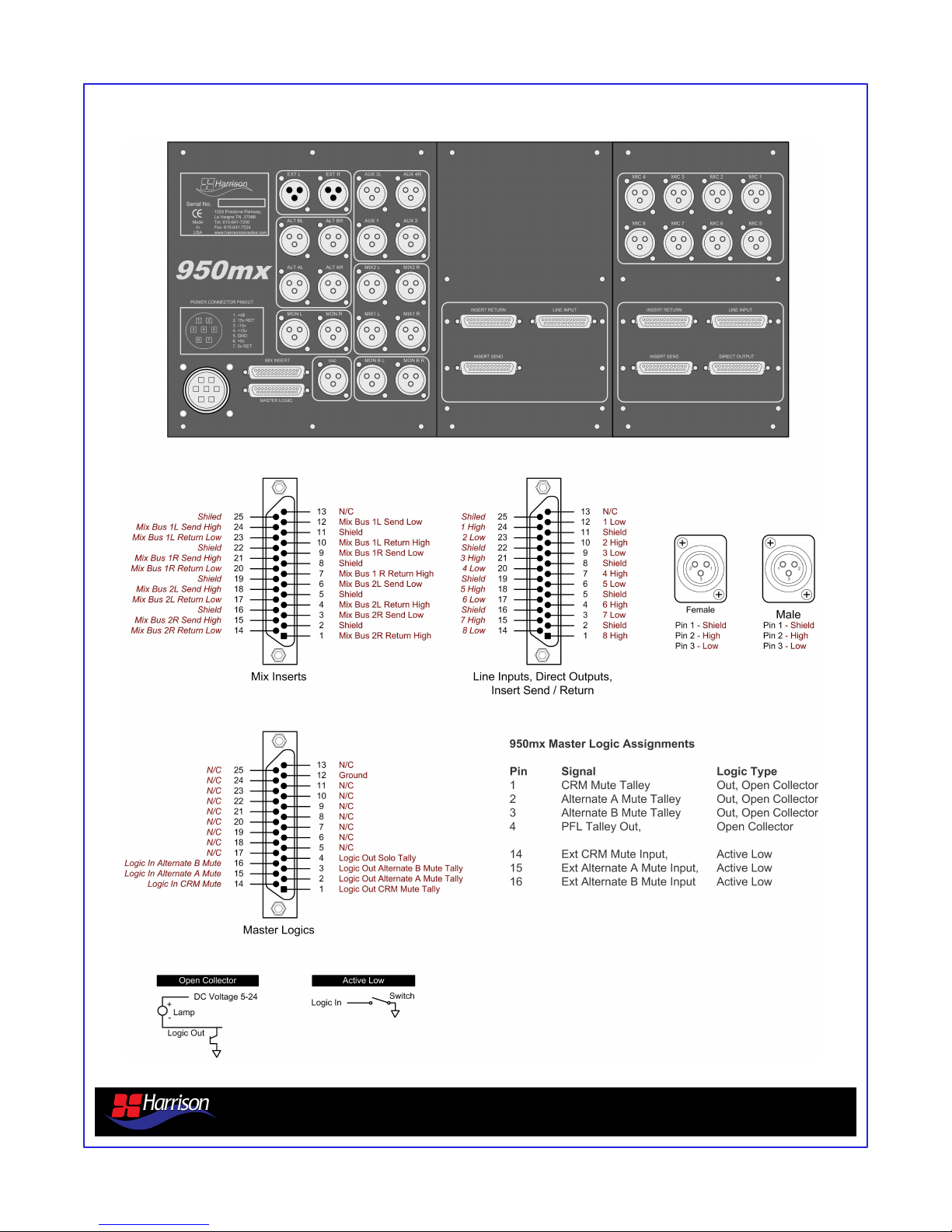
9.0 Rear Panel Connections
950mx analog console overview v1.5 Page 13
Page 14

10.0 Specifications
AUDIO SPECIFICATIONS
The following specifications apply to Harrison 950mx consoles and are subject to change without notice. Harrison 950mx
consoles will be tested to meet only those specifications in effect at the time of final testing. These specifications represent
an overall system and not the individual components of a system. They represent the cumulative effect of all components.
Additionally, these specifications are stated over a wide range of operating conditions representative of actual use conditions
rather than a restrictive set of conditions likely to be seen only when conducting systems tests. Therefore, these
specifications represent the worse case in-use conditions rather than test conditions developed for competitive advantage.
Microphone Return:
Balanced Electronic active
Minimum voltage gain 0dB (fader @ unity, -20dB pad)
Maximum voltage gain 70dB (fader @ unity, no pad)
Nominal input level -16dB through -66dB
(fader @ unity, no pad, ref: 0.775 VRMS, @ +4dB output)
Maximum input level +30dB (fader @ unity, -20dB pad, ref: 0.775 VRMS)
Expected source impedance 150 to 200 Ohms
Actual load impedance 1200 Ohms
Line Inputs:
Balanced Electronic active
Maximum level +30dB (ref: 0.775 VRMS)
Nominal input level +4dB, +6dB, +8dB (ref: 0.775 VRMS)
Expected source impedance 1000 Ohms or less
Actual load impedance 10 kOhms
Line Outputs:
Balanced Electronic active
Maximum level +24dB (ref: 0.775 VRMS)
Nominal input level +4dB, +6dB, +8dB (ref: 0.775 VRMS)
Minimum load impedance 600 Ohms standard (300 Ohms at extra cost)
Actual source impedance 40 Ohms standard (20 Ohms at extra cost)
Logic Returns Pull to ground, nominally pulled up internally via a 10 kOhm resistor
Logic Feeds Open collector, will sink up to 50 V @300mA. Fully protected
Crosstalk Amplitude >80dB (Line In to Mix Bus Out +24 Out @15K)
Frequency Response
Microphone input to Mix Bus line output. Conditions are: input source impedance of 150 to 200 Ohms, output load
impedance of 600 Ohms, channel fader and Mix Bus fader set for unity gain, effective measuring bandwidth of 20 Hz to 20
kHz. Gain shall not deviate from gain at 1kHz for any frequency from 20 Hz to 20 kHz more than +.2dB to -2dB.
Line input to line output. Conditions are: input source impedance of 600 Ohms, output load impedance of 600 Ohms,
channel fader and Mix Bus fader set for unity gain, effective measuring bandwidth of 20 Hz to 20 kHz, and overall gain of
unity. Gain shall not deviate from gain at 1 kHz for any frequency from 20 Hz to 20 kHz by more than +.2dB to -1.0dB.
Noise
Microphone in to Mix Bus line out.
Conditions are: input source impedance of 150 to 200 Ohms, output load impedance of 600 Ohms, channel fader and Mix
Bus fader set for unity gain, one input module is assigned to the Mix Bus output, effective measuring bandwidth of 20 Hz to
20kHz, meter response unweighed to DIN 45 405 and DIN 45 500, meter ballistics true RMS to DIN 45 402 and DIN 45 500,
overall gain is 70 dB at 1 kHz. The equivalent input noise shall not exceed -129dB (ref: 0.775 VRMS). Keeping all the test
conditions the same with the exception that the overall gain is 38dB and the quantity of channels assigned to the output is
four, the noise measured at the output shall not exceed -70dB (ref: 0.775 VRMS). Keeping all the test conditions the same
with the exception that no input channels are assigned to the output, the noise measured at the output shall not exceed -80
(ref: 0.775 VRMS).
950mx analog console overview v1.5 Page 14
Page 15
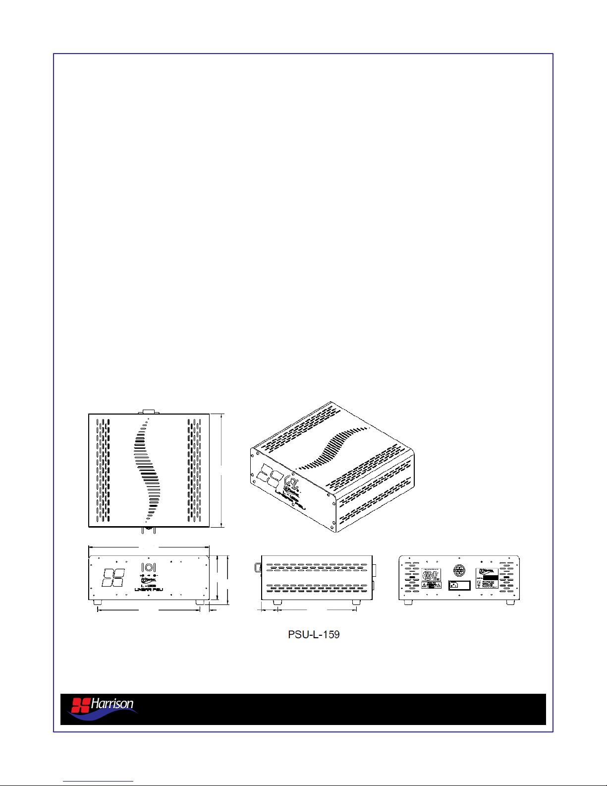
11.0 Power Supply Specifications
The 950mx includes the Harrison L-159 power supply and associated power cable. The included power
cable is 10 feet (3.05 meters) in length. Custom lengths are available for additional cost.
Input Specifications* minimum nominal maximum
Input Voltages (AC) 100 VAC 87 VAC 100 VAC 110 VAC
120 VAC 104 VAC 120 VAC 132 VAC
220 VAC 191 VAC 220 VAC 242 VAC
240 VAC 209 VAC 240 VAC 264 VAC
Input Frequency 47Hz 63Hz
*Derate output current 10% for 50Hz operation. Input voltage tolerance for 230 VAC operation is +15%, -10%.
Output Specifications minimum nominal maximum
Output Adjustment -5% +5%
Efficiency 55%
Ripple and Noise 5.0 mVpk-pk
Output Voltages +15 VDC
-15 VDC
+48VDC
14.14"
15.32"
5.50"
6.12"
13.00" 1.16"
2.08" 10.00"
950mx analog console overview v1.5 Page 15
Page 16
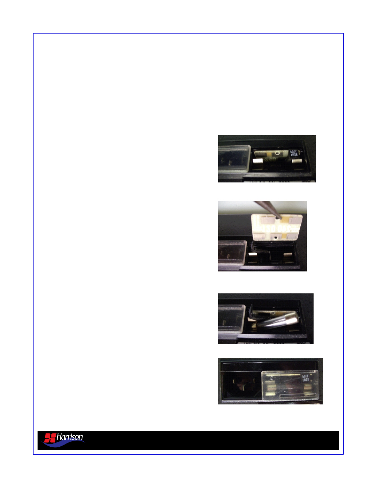
11.0 Power Supply Specifications
Setting PSU Input Voltage
The L-159 power supply can accept four different input voltages. The AC input jack uses a voltage selector
card to set the input voltage of the power supply. The selected input voltage must match the AC line voltage or
damage will occur to the power supply.
1. Locate the AC input on the rear of the L-159.
The AC input should be unplugged before any
adjustment is made.
2. Open cover door and slide fuse-pull lever to
left.
3. Remove the voltage selection card with needle-nose
pliers and select operating voltage by orienting voltage
selection card with the desired voltage on top left side.
4. Push card firmly into module slot.
5. Slide fuse-pull lever to right into normal position
and re-insert fuse into holders.
6. Use caution in selecting correct fuse value.
950mx analog console overview v1.5 Page 16
Page 17

12.0 Environmental Specifications
The environmental requirements for the Harrison 950mx are no more restrictive than for any other piece of
sensitive audio equipment. Please note the following requirements and recommendations:
Ambient Air Temperature Limits
Minimum 58.2ᄎ F (14.6ᄎ C)
Maximum 85ᄎ F (30ᄎ C)
Operation at the upper extremes of the temperature range is not recommended and may increase
the failure rate of component parts. We recommend the temperature range be maintained between
60ᄎ F (15ᄎ C) and 78ᄎ F (25ᄎ C).
Humidity
Humidity should be kept between 10-85% (non-condensing). To prevent condensation, the console
must not be
powered up for several hours after being moved from a cold environment to a heated area.
Atmosphere
Atmospheric contaminants in some areas can reduce the life of electrical contacts and components. Care
must be taken to keep contaminants from coming into contact with your console. Contaminants such as dust,
dirt, ashes, smoking materials, smoke, liquid, etc., may damage your console. Anything other than clean air of
proper temperature and humidity may shorten the life span of the components inside your console. The 950m
should not be placed in environments with either EMI (Electromagnetic Interference) or EMF (Electromagnetic
Fields) which may affect sensitive electronic audio equipment. This includes placement near power mains.
Power Supply Ambient Air Temperature Limits
Minimum 58.2ᄎ F (14.6ᄎ C)
Maximum 85ᄎ F (32ᄎ C)
The environment operating conditions for your Harrison power supplies are the same as for the console. Fresh
ambient air (not preheated air from other equipment) must always be available across the full bottom cover of
the supplies. If the power supply is mounted in an enclosed space forced air cooling is necessary to prevent
overheating.
950mx analog console overview v1.5 Page 17
Page 18

13.0 Module Jumper Settings
Mono Mic/Line Module Jumper Settings
Function Settings
J2 Aux 1 Pre/Post Jump 1-2 for post-fader. Jump 2-3 for prefader.
J3 Aux 2 Pre/Post Jump 1-2 for post-fader. Jump 2-3 for prefader.
J4 Aux 3 Pre/Post Jump 1-2 for post-fader. Jump 2-3 for prefader.
J5 Aux 4 Pre/Post Jump 1-2 for post-fader. Jump 2-3 for prefader.
J6 Logic Options Jump 1-2 for Control Room mute on fader
open.
Stereo Line Module Jumper Settings
Function Settings
J2 Aux 1 Pre/Post Jump 1-2 for post-fader. Jump 2-3 for prefader.
J3 Aux 2 Pre/Post Jump 1-2 for post-fader. Jump 2-3 for prefader.
J4 Aux 3 Pre/Post Jump 1-2 for post-fader. Jump 2-3 for prefader.
J5 Aux 4 Pre/Post Jump 1-2 for post-fader. Jump 2-3 for prefader.
J6 Logic Options Jump 1-2 for Control Room mute on fader
open.
Jump 3-4 for Studio A mute on fader open.
Jump 5-6 for Studio B mute on fader open.
Jump 3-4 for Studio A mute on fader open.
Jump 5-6 for Studio B mute on fader open.
Program Module Jumper Settings
Function Settings
J2 PGM 1L Insert Jump 1-2 to bypass insert. Jump 2-3 to
activate insert.
J3 PGM 1R Insert Jump 1-2 to bypass insert. Jump 2-3 to
activate insert.
J4 PGM 2L Insert Jump 1-2 to bypass insert. Jump 2-3 to
activate insert.
J5 PGM 2R Insert Jump 1-2 to bypass insert. Jump 2-3 to
activate insert.
Control Room Module Jumper Settings
Function Settings
J2 Mute on Talk Jump 1-2 to mute on talk (default).
950mx analog console overview v1.5 Page 18
Page 19

14.0 Contacting Harrison
Harrison Consoles
1024 Firestone Parkway
La Vergne, TN 37086
615-641-7200 Phone
615-641-7224 Fax
Harrison Website
www.harrisonconsoles.com
Sales Contact
Support Contact
950mx analog console overview v1.5 Page 19
 Loading...