

Page 1

TECHNICAL MANUAL
888-2595-001
ZX Series FM
Transmitter
ZX Series
FM Transmitters
ZX2500, ZX3750, ZX5000, ZX7.5, & ZX10
T.M. No. 888-2595-001
© Copyright Harris Corporation 2009, 2010, 2011
All rights reserved
Dec 20, 2011
Rev: J
Page 2

ii 888-2595-001 12/20/11
WARNING: Disconnect primary power prior to servicing.
Page 3

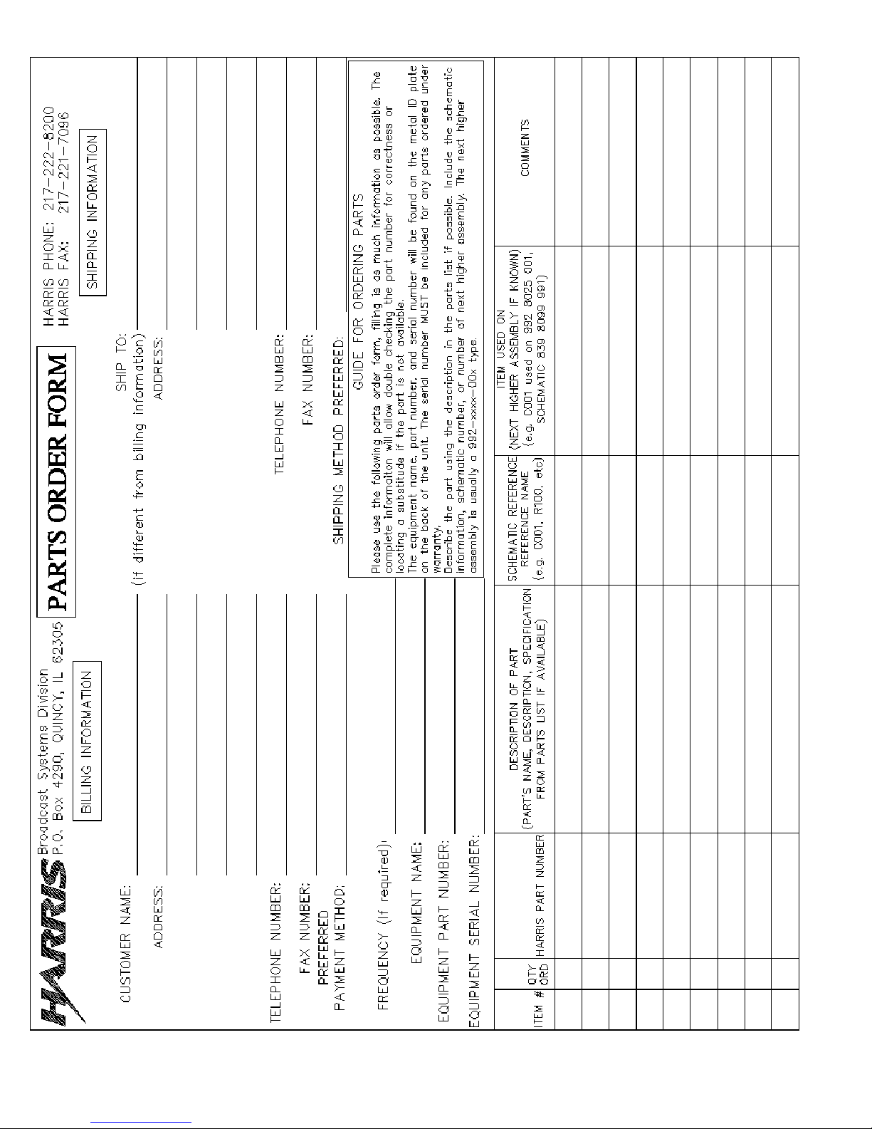
Technical Assistance
Technical and troubleshooting assistance for HARRIS Transmission products is available from
HARRIS Field Service (factory location: Quincy , Illinois, USA) during normal business hours (8:00
AM - 5:00 PM US Central T ime, UTC-6 ). Telephone +1-2 17-222-8200 to contact the Field Service
Department; FAX +1-217-221-7086; or E-mail questions to tsupport@harris.com.
Emergency service is available 24 hours a day, seven days a week, by telephone only.
Other on-line assistance, including technical manuals, white papers, software downloads, and
service bulletins, is available at www.support.harris.broadcast.com (log-in required).
Address written correspondence to Field Service Department, HARRIS Broadcast Communications
Division, P.O. Box 4290, Quincy, Illinois 62305-4290, USA. For other global service contact
information, please visit: http://www.broadcast.harris.com/contact.
NOTE: For all service and parts correspondence, you will need to provide the Sales Order number,
as well as the Serial Number for the transmitter or part in question. For future reference, record
those numbers here: ___________________/____________________
Please provide these numbers for any written request, or have these numbers ready in the event you
choose to call regarding any service or parts requests. For warranty claims they will be required, and
for products out of warranty, they will help us to best identify what specific hardware was shipped.
Replaceable Parts Service
Replacement parts are available from HARRIS Service Parts Department from 7:00 AM to 11:00
PM US Central Time (UTC-6), seven days a week. Telephone +1-217-222-8200 or email
servicepartsreq@harris.com to contact the Service Parts Department.
Emergency replacement parts are available by telephone only , 24 hours a day , seven days a week
by calling +1-217-222-8200.
Unpacking
Carefully unpack the equipment and perform a visual inspection to determine if any apparent
damage was incurred during shipment. Retain the shipping materials until it has been verified that
all equipment has been received undamaged. Locate and retain all PACKING CHECK LISTs. Use
the PACKING CHECK LIST to help locate and identify any components or assemblies which are
removed for shipping and must be reinstalled. Also remove any shipping supports, straps, and
packing materials prior to initial turn on.
Returns And Exchanges
No equipment can be returned unless written approval and a Return Authorization is received from
HARRIS Broadcast Communications Division. Special shipping instructions and coding will be
provided to assure proper handling. Complete details regarding circumstances and reasons for
return are to be included in the request for return. Custom equipment or special order equipment is
not returnable. In those instances where return or exchange of equipment is at the request of the cus
tomer, or convenience of the customer, a restocking fee will be charged. All returns will be sent
freight prepaid and properly insured by the customer. When communicating with HARRIS Broad
cast Communications Division, specify the HARRIS Order Number or Invoice Number
-
-
12/20/11 888-2595-001 iii
WARNING: Disconnect primary power prior to servicing.
Page 4

iv 888-2595-001 12/20/11
WARNING: Disconnect primary power prior to servicing.
Page 5

Manual Revision History
ZX Series FM Transmitter Manual
REV. DATE ECN Pages Affected
A 2009 June
B 2009 July P44299 Added service revisions.
C 2009 Dec 58482 Revised Title Page, MRH1, TOC, added Appendix-A
D 2010 Jan 58572 Revised Title Page, MRH1, Sheets 2-15 and 2-16
E 2010 May 58978 Revised to include 7.5 and 10 kW models
F 2010 Aug 59394 Revised Title Page, MRH1, Sheet 4-2
G 2010 Sep 59487 Revised Title Page, MRH, Table 2-2 on Page 2-14
H 2011 Jan 59870 Updated Appendix A-Web Remote Option
J 2011 Dec 61074 Revised Titl Page, MRH, Sheet 4-8
12/20/11 888-2595-001 MRH-1
WARNING: Disconnect primary power prior to servicing.
Page 6

MRH-2 888-2595-001 12/20/11
WARNING: Disconnect primary power prior to servicing.
Page 7
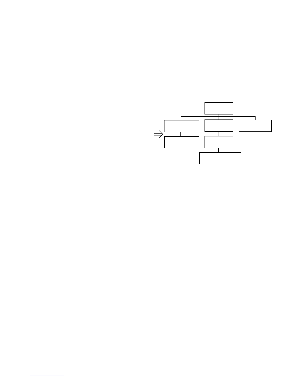
Guide to Using Harris Parts List Information
Transmitter
994 9283 001
Control Cabinet
992 9244 002
Controller Board
992 8344 002
PA Cabinet
992 9400 002
PA Amplifier
992 7894 002
PA Amplifier Board
992 7904 002
Output Cabinet
992 9450 001
The Harris Replaceable Parts List Index portrays a tree structure with the major items being leftmost in the index.
The example below shows the Transmitter as the highest item in the tree structure. If you were to look at the bill
of materials table for the Transmitter you would find the Control Cabinet, the PA Cabinet, and the Output
Cabinet. In the Replaceable Parts List Index the Control Cabinet, PA Cabinet, and Output Cabinet show up one
indentation level below the Transmitter and implies that they are used in the Transmitter. The Controller Board is
indented one level below the Control Cabinet so it will show up in the bill of material for the Control Cabinet.
The tree structure of this same index is shown to the right of the table and shows indentation level versus tree
structure level.
Example of Replaceable Parts List Index and equivalent tree structure:
Replaceable Parts List Index Part Number Page
Table 7-1. Transmitter 994 9283 001 7-2
Table 7-2. Control Cabinet 992 9244 002 7-3
Table 7-3. Controller Board 992 8344 002 7-6
Table 7-4. PA Cabinet 992 9400 002 7-7
Table 7-5. PA Amplifier 994 7894 002 7-9
Table 7-6. PA Amplifier Board 992 7904 002 7-10
Table 7-7. Output Cabinet 992 9450 001 7-12
The part number of the item is shown to the right of the description as is the page in the manual where the bill for
that part number starts. Inside the actual tables, four main headings are used:
NOTE: Inside the individual tables some standard conventions are used:
The term “SEE HIGHER LEVEL BILL” in the description column implies that the reference designated part
• Table #-#. ITEM NAME - HARRIS PART NUMBER - this line gives the information that corresponds
to the
• Replaceable Parts List Index entry;
• HARRIS P/N column gives the ten digit Harris part number (usually in ascending order);
• DESCRIPTION column gives a 25 character or less description of the part number;
• REF. SYMBOLS/EXPLANATIONS column 1) gives the reference designators for the item (i.e., C001,
R102, etc.) that corresponds to the number found in the schematics (C001 in a bill of material is equiva
lent to C1 on the schematic) or 2) gives added information or further explanation (i.e., “Used for 208V
operation only,” or “Used for HT 10LS only,” etc.).
• A # symbol in front of a component such as #C001 under the REF. SYMBOLS/EXPLANATIONS col-
umn means that this item is used on or with C001 and is not the actual part number fo r C001.
• In the ten digit part numbers, if the last three numbers are 000, the item is a part that Harris has pur-
chased and has not manufactured or modified. If the last three numbers are other than 000, the item is
either manufactured by Harris or is purchased from a vendor and modified for use in the Harris product.
• The first three digits of the ten digit part number tell which family the part num ber belongs to - for
example, all electrolytic (can) capacitors will be in the same family (524 xxxx 000). If an electrolytic
(can) capacitor is found to have a 9xx xxxx xxx part number (a number outside of the normal family of
numbers), it has probably been modified in some manner at the Harris factory and will therefore show
up farther down into the individual parts list (because each table is normally sorted in ascending order).
Most Harris made or modified assemblies will have 9xx xxxx xxx numbers associated with them.
number will show up in a bill that is higher in the tree structure. This is often the case for components
that may be frequency determinant or voltage determinant and are called out in a higher level bill
structure that is more customer dependent than the bill at a lower level.
-
12/20/11 888-2595-001 vii
WARNING: Disconnect primary power prior to servicing.
Page 8

viii 888-2595-001 12/20/11
WARNING: Disconnect primary power prior to servicing.
Page 9
12/20/11 888-2595-001 ix
WARNING: Disconnect primary power prior to servicing.
Page 10

x 888-2595-001 12/20/11
WARNING: Disconnect primary power prior to servicing.
Page 11

!
WA RN IN G:
THE CURRENTS AND VOLTAGES IN THIS EQUIPMENT ARE DANGEROUS.
!
WA RN IN G:
!
WA RN IN G:
!
WA RN IN G:
PERSONNEL MUST AT ALL TIMES OBSERVE SAFETY WARNINGS, INSTRUC
TIONS, AND REGULATIONS.
-
This manual is intended as a general guide for trained and qualified personnel who are aware
of the dangers inherent in handling potentially hazardous electrical/electronic circuits. It is not
intended to contain a complete statement of all safety precautions which should be observed
by personnel in using this or other electronic equipment.
The installation, operation, maintenance, and service of this equipment involves risks both to
personnel and equipment, and must be performed only by qualified personnel exercising due
care. HARRIS CORPORATION shall not be responsible for injury or damage resulting from
improper procedures or from the use of improperly trained or inexperienced personnel
performing such tasks. During installation and operation of this equipment, local building
codes and fire protection standards must be observed.
The following National Fire Protection Association (NFPA) standards are recommended as
reference:
- Automatic Fire Detectors, No. 72E
- Installation, Maintenance, and Use of Portable Fire Extinguishers, No. 10
- Halogenated Fire Extinguishing Agent Systems, No. 12A
ALWAYS DISCONNECT POWER BEFORE OPENING COVERS, DOORS, ENCLOSURES, GATES, PANELS, OR SHIELDS. ALWAYS USE GROUNDING STICKS
AND SHORT OUT HIGH VOLTAGE POINTS BEFORE SERVICING. NEVER MAKE
INTERNAL ADJUSTMENTS, PERFORM MAINTENANCE, OR SERVICE WHEN
ALONE OR WHEN FATIGUED.
Do not remove, short-circuit, or tamper with interlock switches on access covers, doors,
enclosures, gates, panels, or shields. Keep away from live circuits, know your equipment and
don’t take chances.
IN CASE OF EMERGENCY, ENSURE THAT POWER HAS BEEN DISCONNECTED.
IF OIL FILLED OR ELECTROLYTIC CAPACIT ORS ARE UTILIZED IN YOUR
EQUIPMENT, AND IF A LEAK OR BULGE IS APPARENT ON THE CAPACITOR
CASE WHEN THE UNIT IS OPENED FOR SERVICE OR MAINTENANCE, ALLOW
THE UNIT TO COOL DOWN BEFORE ATTEMPTING TO REMOVE THE DEFEC
TIVE CAP ACITOR. DO NOT ATTEMPT TO SERVICE A DEFECTIVE CAPACITOR
-
12/20/11 888-2595-001 xi
WARNING: Disconnect primary power prior to servicing.
Page 12
WHILE IT IS HOT DUE TO THE POSSIBILITY OF A CASE RUPTURE AND SUBSEQUENT INJURY.
xii 888-2595-001 12/20/11
WARNING: Disconnect primary power prior to servicing.
Page 13

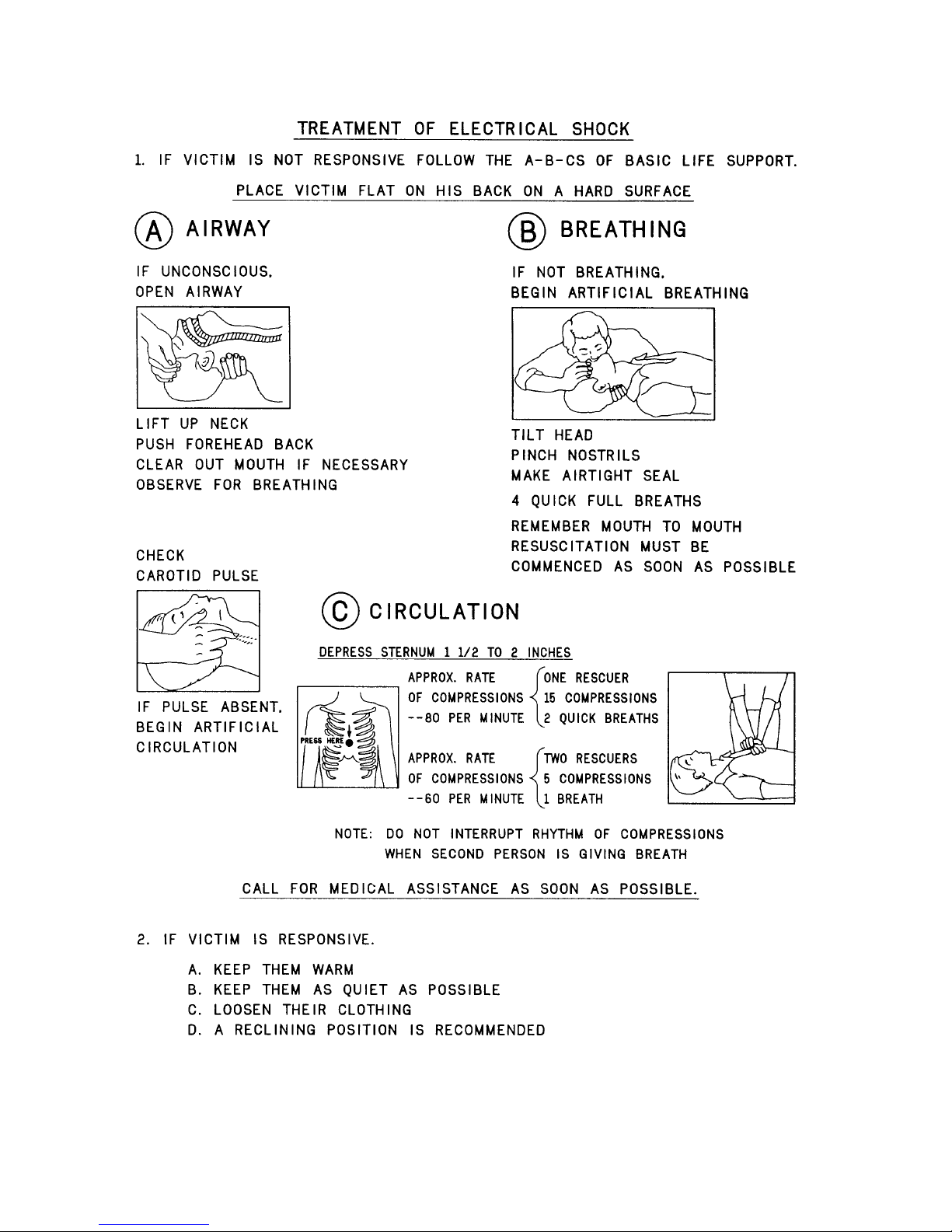
FIRST-AID
NOTE:
Personnel engaged in the installation, operation, maintenance, or servicing of this equipment
are urged to become familiar with first-aid theory and practices. The following information is
not intended to be complete first-aid procedures; it is brief and is only to be used as a
reference. It is the duty of all personnel using the equipment to be prepared to give adequate
Emergency First Aid and thereby prevent avoidable loss of life.
Treatment of Electrical Burns
1. Extensive burned and broken skin
a. Cover area with clean sheet or cloth. (Cleanest available cloth
article.)
b. Do not break blisters, remove tissue, remove adhered particles of
clothing, or apply any salve or ointment.
c. Treat victim for shock as required.
d. Arrange transportation to a hospital as quickly as possible.
e. If arms or legs are affected keep them elevated.
If medical help will not be available within an hour and the victim is conscious and
not vomiting, give him a weak solution of salt and soda: 1 level teaspoonful of salt
and 1/2 level teaspoonful of baking soda to each quart of water (neither hot or
cold). Allow victim to sip slowly about 4 ounces (a half of glass) over a period of
15 minutes. Discontinue fluid if vomiting occurs. (Do not give alcohol.)
2. Less severe burns - (1st & 2nd degree)
a. Apply cool (not ice cold) compresses using the cleanest available
cloth article.
b. Do not break blisters, remove tissue, remove adhered particles of
clothing, or apply salve or ointment.
c. Apply clean dry dressing if necessary.
d. Treat victim for shock as required.
e. Arrange transportation to a hospital as quickly as possible.
f. If arms or legs are affected keep them elevated.
REFERENCE:
ILLINOIS HEART ASSOCIATION
AMERICAN RED CROSS ST ANDARD FIRST AID AND PERSONAL SAFETY
MANUAL (SECOND EDITION)
12/20/11 888-2595-001 xiii
WARNING: Disconnect primary power prior to servicing.
Page 14

xiv 888-2595-001 12/20/11
WARNING: Disconnect primary power prior to servicing.
Page 15

Table of Contents
Section 1
Introduction
Manual Contents . . . . . . . . . . . . . . . . . . . . . . . . . . 1-1
Features / Benefits. . . . . . . . . . . . . . . . . . . . . . . . . 1-2
General Product Description. . . . . . . . . . . . . . . . . 1-3
Exciter. . . . . . . . . . . . . . . . . . . . . . . . . . . . . . . . . 1-3
Amplifier . . . . . . . . . . . . . . . . . . . . . . . . . . . . . . 1-4
Transmitter Nomenclature. . . . . . . . . . . . . . . . . . . 1-4
Tri-mode Operation. . . . . . . . . . . . . . . . . . . . . . . . 1-5
ZX Transmitter General Construction. . . . . . . . . . 1-5
Simplified Block Diagrams. . . . . . . . . . . . . . . . . . 1-8
Major Subassemblies. . . . . . . . . . . . . . . . . . . . . . 1-13
Transmitter Accessories . . . . . . . . . . . . . . . . . . . 1-18
Customized Rack Integration . . . . . . . . . . . . . . 1-18
AC Distribution & Signal Monitor Chassis . . . 1-18
Directional Coupler or Wattmeter . . . . . . . . . . 1-18
Dual-Drive / Main-alternate Switcher . . . . . . . 1-19
Specifications . . . . . . . . . . . . . . . . . . . . . . . . . . . 1-20
Section 2
Installation
Field Services . . . . . . . . . . . . . . . . . . . . . . . . . . . . 2-1
Installation. . . . . . . . . . . . . . . . . . . . . . . . . . . . . 2-1
Commissioning. . . . . . . . . . . . . . . . . . . . . . . . . . 2-2
Unpacking . . . . . . . . . . . . . . . . . . . . . . . . . . . . . . . 2-2
Returns and Exchanges . . . . . . . . . . . . . . . . . . . . . 2-2
Transmitter Documentation. . . . . . . . . . . . . . . . . . 2-2
Installation and Outline Drawings . . . . . . . . . . . 2-3
Site Selection. . . . . . . . . . . . . . . . . . . . . . . . . . . . . 2-3
AC Mains Requirements. . . . . . . . . . . . . . . . . . . . 2-4
Transmitters with AC Distribution Chassis. . . . 2-4
Transmitters without AC Distribution Chassis. . 2-5
Surge Suppression Devices. . . . . . . . . . . . . . . . . . 2-7
Ground Requirements . . . . . . . . . . . . . . . . . . . . . . 2-7
Overview of RF Grounding Practices . . . . . . . . 2-8
Cooling System Requirements . . . . . . . . . . . . . . . 2-9
Personnel and Equipment Protection . . . . . . . . . 2-11
Safety circuits. . . . . . . . . . . . . . . . . . . . . . . . . . 2-11
Remote Control Installation . . . . . . . . . . . . . . . . 2-12
Exciter Connections . . . . . . . . . . . . . . . . . . . . . 2-17
System Bus Connections. . . . . . . . . . . . . . . . . . . 2-20
Initial Start-up Procedure . . . . . . . . . . . . . . . . . . 2-20
Section 3
Operation
Introduction. . . . . . . . . . . . . . . . . . . . . . . . . . . . . . .3-1
Controls and Indicators. . . . . . . . . . . . . . . . . . . . . .3-1
Front Panel . . . . . . . . . . . . . . . . . . . . . . . . . . . . . .3-1
Controller board . . . . . . . . . . . . . . . . . . . . . . . . . .3-3
Internal LEDs. . . . . . . . . . . . . . . . . . . . . . . . . . . .3-6
System Metering Assembly . . . . . . . . . . . . . . . . . .3-7
Basic Operational Procedures. . . . . . . . . . . . . . . . .3-8
ON/OFF Procedure . . . . . . . . . . . . . . . . . . . . . . .3-8
Power Raise/Lower Procedure. . . . . . . . . . . . . . .3-9
Switch Operating Mode Procedure
(FlexStar HDX Exciter) . . . . . . . . . . . . . . . . . . . .3-9
Basic Functional Check Procedure . . . . . . . . . .3-10
Section 4
Theory of Operation
Introduction. . . . . . . . . . . . . . . . . . . . . . . . . . . . . . .4-1
RF Interconnect Wiring Diagram . . . . . . . . . . . . . .4-1
Output Assembly . . . . . . . . . . . . . . . . . . . . . . . . . .4 -2
AC-DC Interconnect Wiring Diagram . . . . . . . . . .4-4
PA Backplane. . . . . . . . . . . . . . . . . . . . . . . . . . . . .4-5
PA Reverse Power Alarm. . . . . . . . . . . . . . . . . . .4-5
PA Temperature Alarm. . . . . . . . . . . . . . . . . . . . .4-6
PA Current Alarm. . . . . . . . . . . . . . . . . . . . . . . . .4-6
Socket Interlock Module Fault Sensor. . . . . . . . .4-7
IPA Backplane. . . . . . . . . . . . . . . . . . . . . . . . . . . . .4-7
I/O Filter PCB. . . . . . . . . . . . . . . . . . . . . . . . . . . . .4-8
8X PS Interface PCB . . . . . . . . . . . . . . . . . . . . . . .4-9
5X Fan Monitor PCB . . . . . . . . . . . . . . . . . . . . . .4-10
16X Load PCB . . . . . . . . . . . . . . . . . . . . . . . . . . .4-11
PA, IBOC PCB . . . . . . . . . . . . . . . . . . . . . . . . . . .4-11
Transmitter Controller PCB . . . . . . . . . . . . . . . . .4-12
On/Off Control. . . . . . . . . . . . . . . . . . . . . . . . . .4-12
Auto Restart. . . . . . . . . . . . . . . . . . . . . . . . . . .4-13
APC Circuit and Power Level Adjust . . . . . . . .4-14
Operating Mode and Bias Level Control . . . . . .4-16
Metering . . . . . . . . . . . . . . . . . . . . . . . . . . . . . . .4-17
Fault and Status Signaling . . . . . . . . . . . . . . . . .4-19
Load Temperature Fault Sensor . . . . . . . . . . . . .4-20
Ambient Temperature Sensor. . . . . . . . . . . . . . .4-20
Drain Voltage Adjust . . . . . . . . . . . . . . . . . . . . .4-20
System Metering Assembly . . . . . . . . . . . . . . . . .4-20
1
Page 16

Table of Contents (Continued)
System Interconnect (multi-PA chassis
transmitters). . . . . . . . . . . . . . . . . . . . . . . . . . . . . 4-21
Command Sharing. . . . . . . . . . . . . . . . . . . . . . . 4-21
Power Control Sharing . . . . . . . . . . . . . . . . . . . 4-23
Section 5
Maintenance and Alignments
Introduction . . . . . . . . . . . . . . . . . . . . . . . . . . . . . . 5-1
General Maintenance Guidelines. . . . . . . . . . . . . . 5-2
Personnel Training . . . . . . . . . . . . . . . . . . . . . . . 5-2
Recommended Tools and Equipment . . . . . . . . . 5-3
Spares Holding . . . . . . . . . . . . . . . . . . . . . . . . . . 5-5
Safety Precautions. . . . . . . . . . . . . . . . . . . . . . . . 5-5
Transmitter Logbook. . . . . . . . . . . . . . . . . . . . . . 5-6
Maintenance Logbook. . . . . . . . . . . . . . . . . . . . . 5-6
Routine Maintenance . . . . . . . . . . . . . . . . . . . . . 5-7
MTBF Estimates . . . . . . . . . . . . . . . . . . . . . . . . 5-7
Basic Maintenance Procedures . . . . . . . . . . . . . . . 5-8
Power Amplifier (PA) Module Swap
Procedure. . . . . . . . . . . . . . . . . . . . . . . . . . . . . . . 5-8
Power Supply (PS) Module Swap Procedure . . 5-10
Air Filter Replacement Procedure. . . . . . . . . . . 5-11
PA Module Cleaning Procedure . . . . . . . . . . . . 5-12
Advanced Maintenance Procedures. . . . . . . . . . . 5-13
Advanced Functional Check . . . . . . . . . . . . . . . 5-13
Forward Power Meter Calibration . . . . . . . . . . 5-16
Precision Directional Coupler . . . . . . . . . . . . 5-17
Reverse Power Meter Calibration. . . . . . . . . . . 5-18
Set Transmitter Power Level (Case 1:
internal transmitter APC control) . . . . . . . . . . . 5-19
Set Transmitter Power Level (Case 2:
exciter APC control with FlexStar HDX). . . . . 5-21
APC Setup for Multiple PA Chassis . . . . . . . . . 5-23
Set User Reverse Power Foldback Threshold
(ZX2500 / ZX3750 / ZX5000). . . . . . . . . . . . . 5-24
Set User Reverse Power Foldback Threshold
(ZX7.5, ZX10) . . . . . . . . . . . . . . . . . . . . . . . . . 5-25
Periodic Cleaning and Inspection. . . . . . . . . . . 5-26
Service one PA chassis while transmitter is
on air (ZX7.5/ZX10). . . . . . . . . . . . . . . . . . . . . 5-28
Check balance by disconnecting load
(ZX7.5/ZX10) . . . . . . . . . . . . . . . . . . . . . . . . . . 5-28
Special Part Replacement Notes . . . . . . . . . . . . . 5-30
PA Module (992-9992-041G or otherwise) . . . 5-30
PA Amplifier Assembly (PWA, PA)
(992-9992-021G or otherwise) . . . . . . . . . . . . . 5-30
PS Module (736-0445-000) . . . . . . . . . . . . . . . 5-32
Transmitter Controller PCB (901-0203-541) . . 5-33
PA Backplane PCB (901-0203-381). . . . . . . . . 5-33
IPA Backplane PCB (901-0203-581) . . . . . . . . 5-33
PS Interface PCB (901-0203-531) . . . . . . . . . . 5-33
RF Output Assembly
(971-0023-026/027/028). . . . . . . . . . . . . . . . . . 5-34
Output Assembly Ballast Load
(700-1225-000). . . . . . . . . . . . . . . . . . . . . . . . . 5-38
RF Splitter (901-0203-511/561/571) . . . . . . . . 5-39
I/O Filter PCB (901-0203-551). . . . . . . . . . . . . 5-40
Web Remote PCB (901-0203-391T) . . . . . . . . 5-40
Fan Monitor PCB (901-0203-441) . . . . . . . . . . 5-40
Cooling Fans (430-0458-000). . . . . . . . . . . . . . 5-40
Front Panel Multimeter (632-1201-000). . . . . . 5-40
AC Mains Filter
(476-0528-000 or 609-0125-000). . . . . . . . . . . 5-41
Front Panel Filter (943-5567-408) . . . . . . . . . . 5-41
2X IPA Splitter (901-0203-591) . . . . . . . . . . . . 5-41
Input 3dB Attenuator (971-0023-050) . . . . . . . 5-41
System Metering Assembly . . . . . . . . . . . . . . . 5-41
Output Combiner (3dB Hybrid) . . . . . . . . . . . . 5-41
2.5 kW RF Load . . . . . . . . . . . . . . . . . . . . . . . . 5-42
Section 6
Troubleshooting
Contacting Harris Service . . . . . . . . . . . . . . . . . . . 6-1
Troubleshooting Table. . . . . . . . . . . . . . . . . . . . . . 6-2
Section 7
Parts List
ZX5000 Replaceable Parts List. . . . . . . . . . . . . . . 7-2
ZX10 Replaceable Parts List. . . . . . . . . . . . . . . . . 7-7
Appendix A - FM Web Remote
Option
Introduction . . . . . . . . . . . . . . . . . . . . . . . . . . . . . .A-1
General Product Description. . . . . . . . . . . . . . . .A-1
Installation. . . . . . . . . . . . . . . . . . . . . . . . . . . . . . .A-3
Internet Security . . . . . . . . . . . . . . . . . . . . . . . . .A-3
2
Page 17

Table of Contents
Installation Procedure. . . . . . . . . . . . . . . . . . . . . A-4
Operation. . . . . . . . . . . . . . . . . . . . . . . . . . . . . . . . A-5
Access main page . . . . . . . . . . . . . . . . . . . . . . . . A-5
Theory of Operation . . . . . . . . . . . . . . . . . . . . . . A-11
Maintenance . . . . . . . . . . . . . . . . . . . . . . . . . . . . A-12
Access Configuration Page. . . . . . . . . . . . . . . . A-12
Perform Simple Reset. . . . . . . . . . . . . . . . . . . . A-17
Perform Expert Reset . . . . . . . . . . . . . . . . . . . . A-18
Change Clock Battery. . . . . . . . . . . . . . . . . . . . A-19
Calibrate Clock Speed . . . . . . . . . . . . . . . . . . . A-20
Use Microchip Discoverer Utility . . . . . . . . . . A-20
Troubleshooting. . . . . . . . . . . . . . . . . . . . . . . . . . A-22
USB Flash Drive. . . . . . . . . . . . . . . . . . . . . . . . . A-23
3
Page 18

Table of Contents (Continued)
4
Page 19

ZX Series
NOTE:
Section 1
Introduction
1.1 Manual Contents
This technical manual addresses the following Harris ZX series of solid-state radio
transmitters:
• ZX2500 – 2.5 kW FM transmitter
• ZX3750 – 3.75 kW FM transmitter
• ZX5000 – 5 kW FM transmitter
1
• ZX7.5 – 7.5 kW FM transmitter
• ZX10 – 10 kW FM transmitter
This manual does not address the ZX transmitter models listed below:
• ZX500 – 500W FM transmitter
• ZX1000 – 1000W FM transmitter
• ZX2000 – 2000W FM transmitter
• ZX3500 – 3500W FM transmitter
These transmitters are addressed in Instruction Book (888-2594-001).
This manual contains the following sections:
• Section 1: Introduction, identifies the versions of the product available and the possi-
ble options.
• Section 2: Installation, details the procedures to receive, install, and commission the
transmitter for use, including an initial turn-on procedure.
12/20/11 888-2595-001 1-1
WARNING: Disconnect primary power prior to servicing.
Page 20

Section 1 Introduction
• Section 3: Operation, describes operation of the equipment and is intended to be the
primary section referenced by operating personnel.
• Section 4: Theory of Operation, is included to help service personnel to understand
the inner workings of the transmitter.
• Section 5: Maintenance, lists and explains alignments and adjustments that could be
required to maintain the transmitter once in operation.
• Section 6: Troubleshooting, is included as a servicing aid to be used along with Sec-
tions 4 and 5 by qualified service personnel to identify and correct an equipment malfunction.
• Section 7: Parts List, is a comprehensive listing of the components that may be
replaced in the field.
• Appendix A: FM WEB remote option, proivdes information about the optional
WEB remote interface card.
1.2 Features / Benefits
ZX Series
The Harris ZX Series of transmitters offers the following useful features and benefits:
• HD Radio capable with on-the-fly switching between FM, FM+HD, or HD mode
when used with FlexStar exciter.
• Broadband design to eliminate tuning adjustments from 87.5 MHz through 108 MHz
(N+1 capable). Frequency change can be done electronically in seconds with MicroMax or FlexStar exciter or Digit exciter with external controller.
• Redundant hot-plug RF amplifier modules allow module replacement while transmit-
ter is in operation.
• Redundant hot-plug power supplies modules allow module replacement while trans-
mitter is in operation, including transmitter logic supplies. (each PS module has both
50V and 5V logic supplies)
• Redundant cooling fans allow transmitter to operate at full power for extended peri-
ods with a fan failure, while fan tachometer alarm notifies service personnel of failure condition.
• Three independent AC mains inputs per amplifier chassis and regulated power sup-
plies allow transmitter to accept a wide range of single or three phase mains power
without concern for line balance or rotation.
• Redundant IPA amplifiers and PA splitters eliminate a single point of failure.
• Non software-based controller for simple, repeatable operation. Does not require
UPS or battery to retain settings during AC mains failures.
• EIA rack mounting for easy installation with only 16RU height for 5000W amplifier .
1-2 888-2595-001 12/20/11
WARNING: Disconnect primary power prior to servicing.
Page 21
ZX Series
(Flexstar HDX exciter shown)
[002] Amplifier
[001] Exciter
[001]
[002]
• Optional air plenum available for interface to an external ducted air system.
• Precision directional RF sample port provided for customer use.
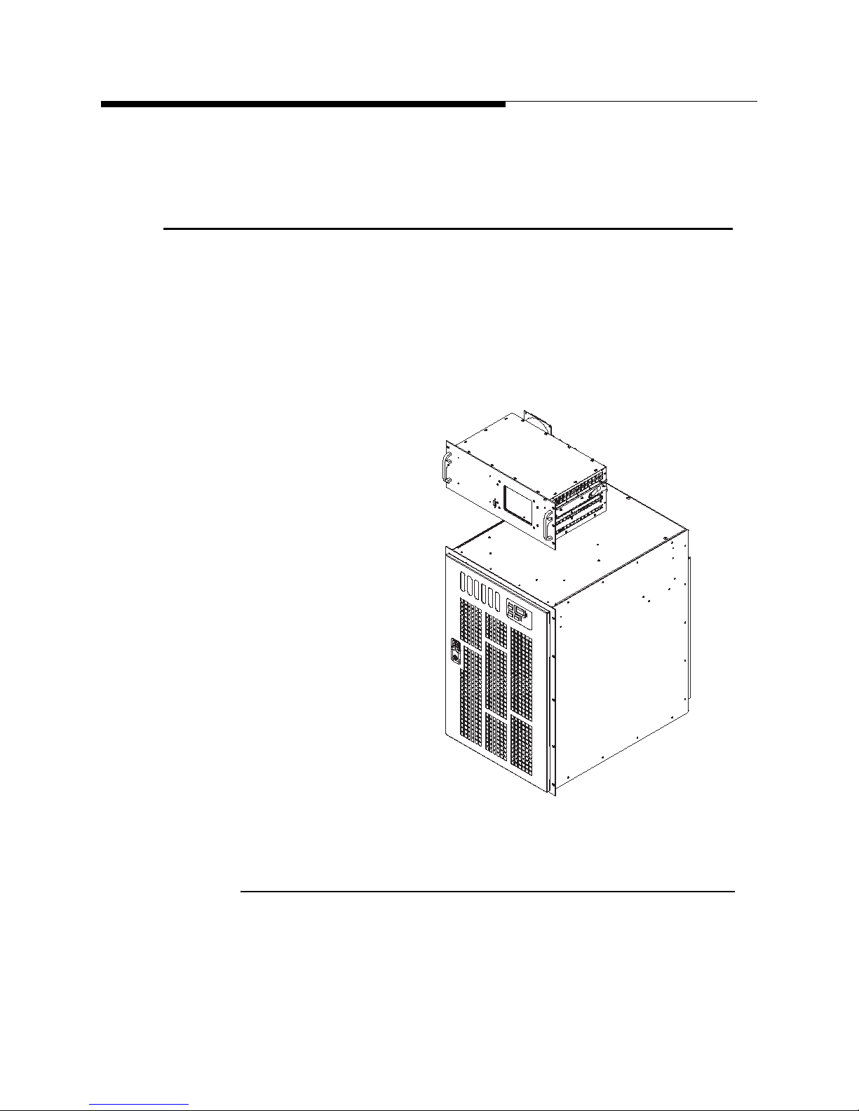
1.3 General Product Description
The ZX series of solid state transmitters is designed to synthesize and amplify
radiofrequency signals in the FM broadcast band (87.5MHz -108MHz).
The complete ZX transmitter consists of one or more of each of two major assemblies:
an FM exciter and the ZX amplifier chassis. These are shown in Figure 1-1.
Section 1 Introduction
12/20/11 888-2595-001 1-3
1.3.1 Exciter
The exciter accepts an audio signal in either analog or digital format and modulates it
onto an RF carrier. Depending on the format of modulation, digital HD Radio or
traditional FM, the exciter may be any one of these Harris exciters:
Figure 1-1 Major subassemblies of ZX series transmitter
WARNING: Disconnect primary power prior to servicing.
Page 22

Section 1 Introduction
NOTE:
• Micromax FM – FM exciter with analog modulator.
• Digit CD – Digitally synthesized FM exciter.
• FlexStar HDX - Tri-mode exciter capable of either traditional FM or digital HD
Radio transmissions.
1.3.2 Amplifier
The amplifier chassis accepts a low level on-channel RF signal from the exciter and
amplifies it to the desired output level for transmission. The transmitter models
addressed in this manual have five standard FM power levels: 2500W, 3750W, 5000W,
7.5kW & 10kW.
This manual chiefly addresses the ZX amplifier chassis and the operation of the
transmitter as a whole. A manual dedicated to the exciter is provided separately.
1.4 Transmitter Nomenclature
ZX Series
The complete ZX transmitter is named according to the particular combination of
exciter and amplifier chassis being employed. The number following the ZX prefix
indicates the full nominal FM power level,either in watts for power levels below
5000W or in kilowatts for power levels above 5000W. A suffix of FM, CD, FLX, or
HD+ is assigned according to the exciter type.
For example:
ZX5000 = 5000W amplifier with no exciter
ZX5000MX = 5000W amplifier with MicroMax
ZX5000CD = 5000W amplifier with DIGIT CD
ZX5000FLX = 5000W amplifier with FlexStar
only, no HD Radio)
ZX5000HDPL (HD plus) = 5000W amplifier with FlexStar
exciter (both FM and HD Radio capable)
FM exciter
(TM)
digital FM exciter
(TM)
HDX-FM digital FM exciter (FM
(TM)
HDX-FM digital FM
(TM)
In addition, the FlexStar exciter may have one or two RF outputs, depending on
the model number. The use of dual RF outputs is advantageous in certain appli
cations.
1-4 888-2595-001 12/20/11
WARNING: Disconnect primary power prior to servicing.
-
Page 23

ZX Series
FLX-11 = single FM output
FLX-12 = dual FM outputs
HDPL-21 = single tri-mode output (FM, FM+HD, HD)
HDPL-22 = dual tri-mode outputs
1.5 Tri-mode Operation
All ZX transmitters are designed to operate in any one of three different modes:
1. FM mode = traditional FM modulation
2. FM+HD mode = hybrid mode with analog and digital HD Radio simulcast
3. HD mode = digital HD Radio modulation only
The determination of operating mode is made by the exciter. To transmit a digital HD
Radio signal, an HD Radio exciter, such as the FlexStar HDX exciter is required. The
ZX amplifier can switch on-the-fly between all three operating modes, as commanded
by the exciter through an exciter interface cable.
Section 1 Introduction
1.6 ZX Transmitter General Construction
The ZX transmitter features all solid-state construction and utilizes a series of FETbased power amplifier (PA) modules to amplify the RF signal. In addition to RF drive
power from the exciter, these PA modules utilize 50V DC power supplied by
switchmode power supply (PS) modules. Both the PA and PS modules are hotpluggable and may be inserted and removed from the transmitter while it is on the air.
12/20/11 888-2595-001 1-5
WARNING: Disconnect primary power prior to servicing.
Page 24
Section 1 Introduction
NOTE:
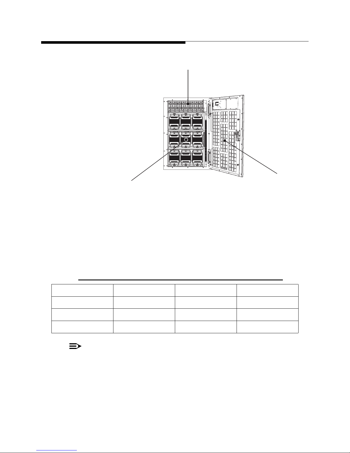
[101]
[102]
[103]
[101] Power supply (PS) module
[102] Front door
[103] Power amplifier (PA) module
ZX Series
The number of PA and PS modules, size, weight, and other important parameters vary
according to the transmitter model and desired power level. Information on the number
of PA and PS modules as a function of transmitter model for power levels of 5000W
and below is given below in Table 1-1 and Figure 1-3.
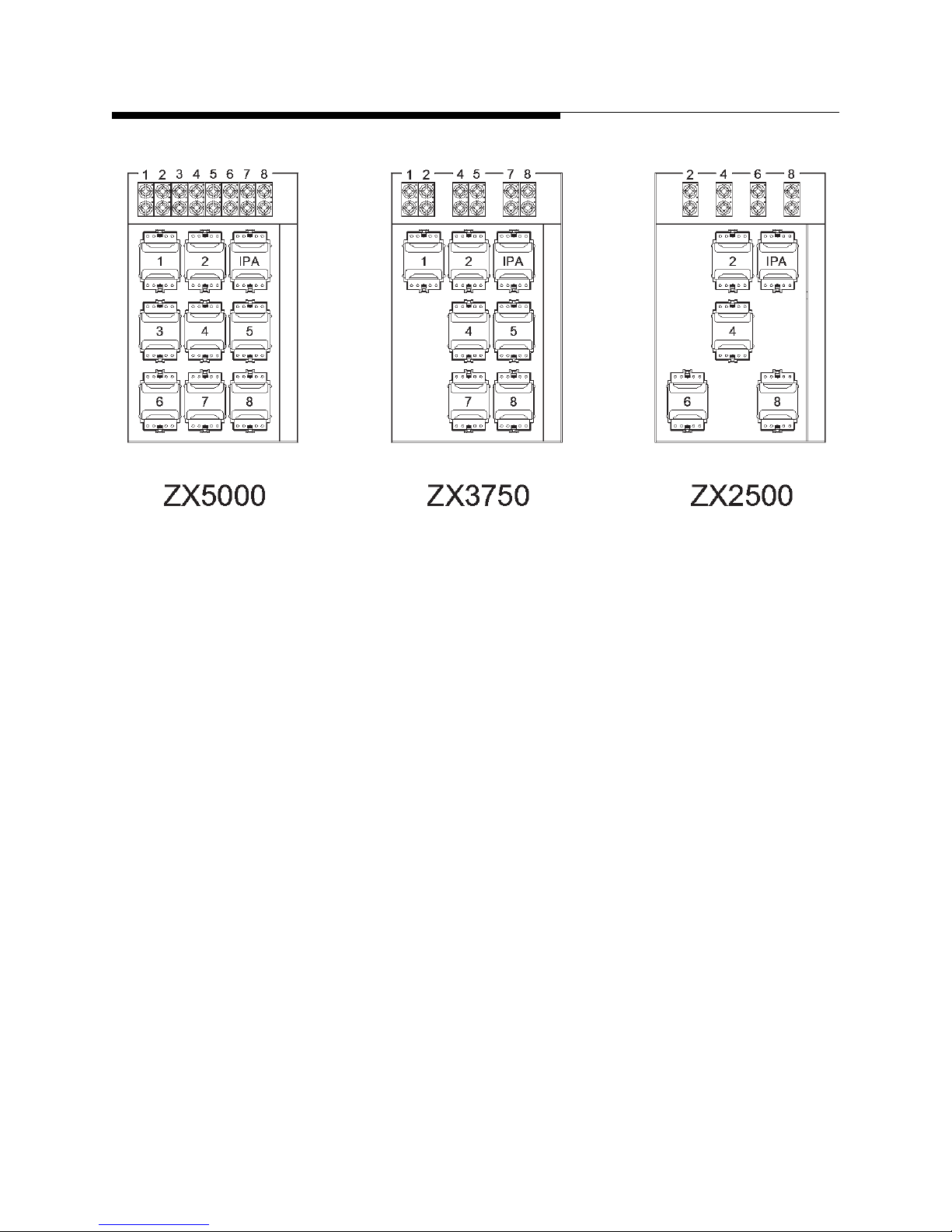
Table 1-1 Complement of Modules vs Transmitter Model
Model PA Modules* PS Modules Cooling Fans
ZX5000 8 + 1 8 5
ZX3750 6 + 1 6 5
ZX2500 4 + 1 4 5
Figure 1-2 PA and PS modules in ZX series amplifier
“+1” designation indicates an IPA module: a PA module installed in the IPA position.
1-6 888-2595-001 12/20/11
WARNING: Disconnect primary power prior to servicing.
Page 25
ZX Series
Section 1 Introduction
Figure 1-3 Positions of PA and PS modules in various ZX series transmitter models
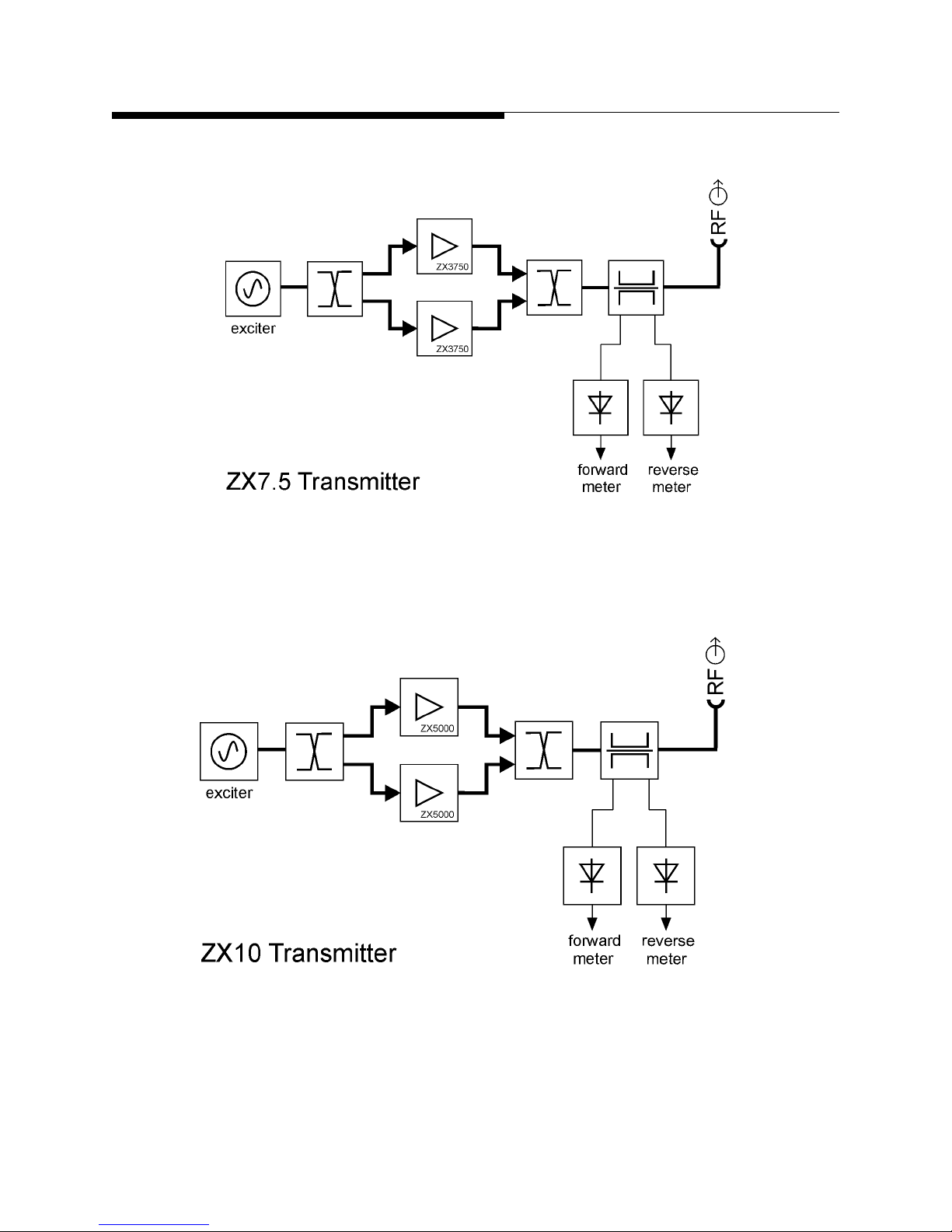
The transmitter models at 7.5kW and above are made by combining the outputs of
multiple ZX3750 or ZX5000 amplifier chassis in an integrated system. The number of
amplifier chassis per model is as follows:
ZX7.5 = 2 x ZX3750
ZX10 = 2 x ZX5000
Additional information on important transmitter parameters, such as size, weight, and
power consumption, may be found in drawing 839-8464-033 Outline Drawing, ZX
Transmitters in the drawing package accompanying this manual.
12/20/11 888-2595-001 1-7
WARNING: Disconnect primary power prior to servicing.
Page 26

Section 1 Introduction
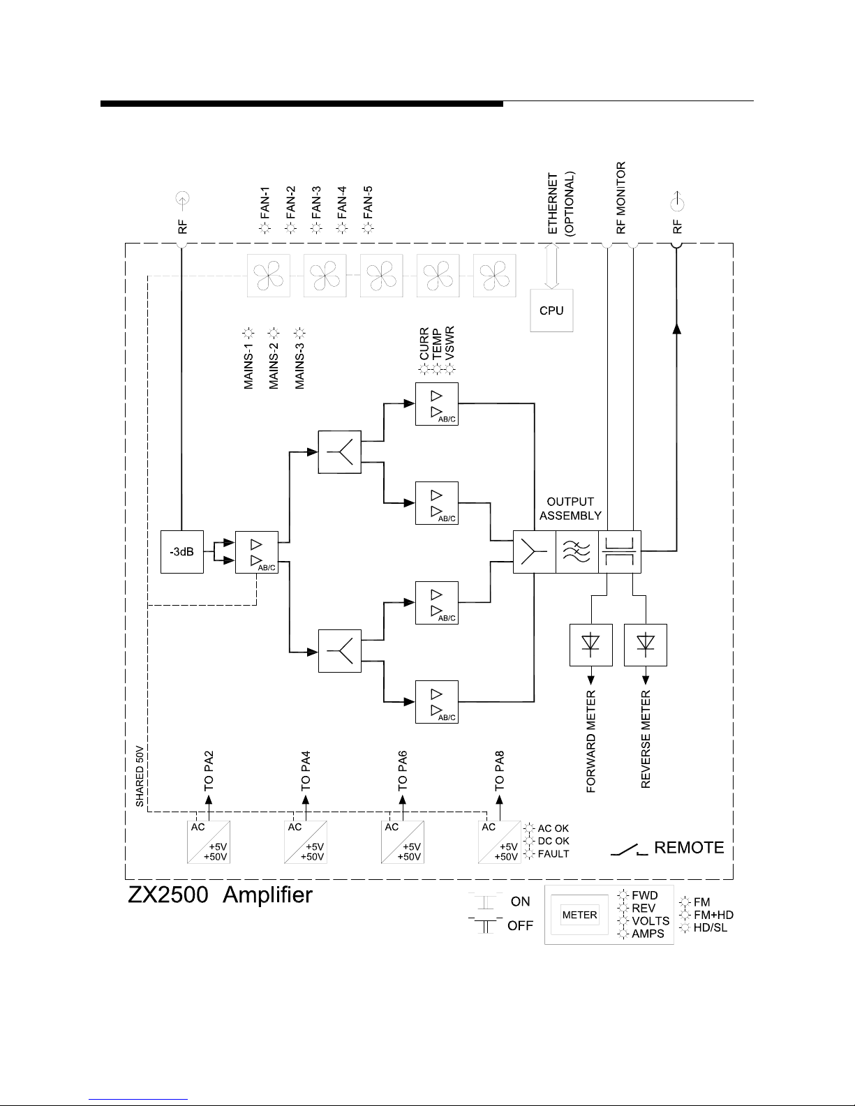
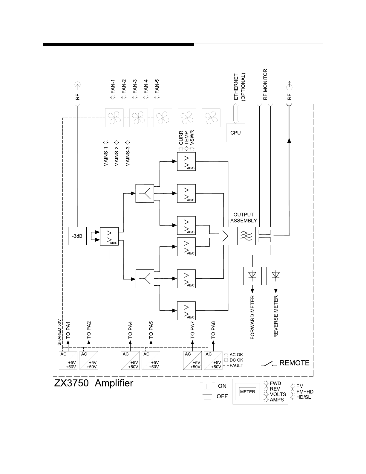
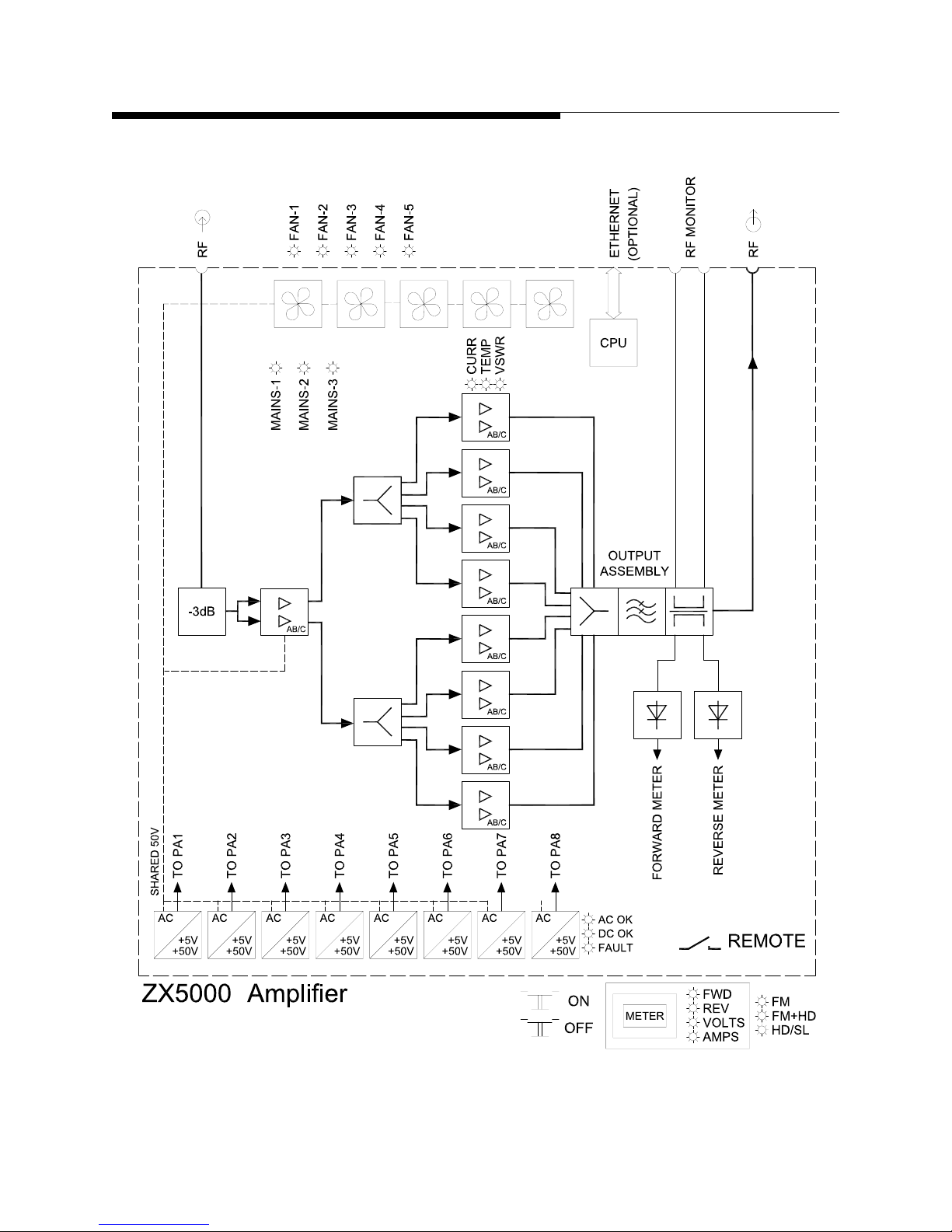
1.7 Simplified Block Diagrams
Figures 1-4 through 1-6 provide simplified block diagrams of the amplifier models
discussed in this manual. Figures 1-7 and 1-8 provide a simplified block diagram of the
ZX7.5 and ZX10 model transmitters. Consult the exciter manual for a block diagram of
the exciter.
ZX Series
1-8 888-2595-001 12/20/11
WARNING: Disconnect primary power prior to servicing.
Page 27
ZX Series
Section 1 Introduction
Figure 1-4 ZX2500 amplifier simplified block diagram
12/20/11 888-2595-001 1-9
WARNING: Disconnect primary power prior to servicing.
Page 28
Section 1 Introduction
ZX Series
Figure 1-5 ZX3750 amplifier simplified block diagram
1-10 888-2595-001 12/20/11
WARNING: Disconnect primary power prior to servicing.
Page 29
ZX Series
Section 1 Introduction
Figure 1-6 ZX5000 amplifier simplified block diagram
12/20/11 888-2595-001 1-11
WARNING: Disconnect primary power prior to servicing.
Page 30
Section 1 Introduction
ZX Series
Figure 1-7 ZX7.5 similified block diagram
Figure 1-8 ZX10 simplified block diagram
1-12 888-2595-001 12/20/11
WARNING: Disconnect primary power prior to servicing.
Page 31

ZX Series
[002]
[003]
[004]
[005]
[006]
[001]
[001] PS module
[002] Controller board
[003] Filter door and air filter
[004] Hex key to open rear door
[005] Air intake plenum leading to
output assembly heatsink
[006] PA module
1.8 Major Subassemblies
Figures 1-7 through 1-9 identify some of the major subassemblies contained the ZX
series amplifier. Figures 1-10 through 1-14 indentify the major subassemblies found in
full-cabinet transmitters with output powers of 7.5kW and above.The role of these
subassemblies is discussed in detail in Section 4 – Theory of Operation.
Section 1 Introduction
Figure 1-9 ZX5000 amplifier front view with front face removed
12/20/11 888-2595-001 1-13
WARNING: Disconnect primary power prior to servicing.
Page 32

Section 1 Introduction
[203]
[204]
[205]
[206]
[207]
[201]
[202]
[201] User interface subpanel:
RF forward monitor port (SMA-M)
RF reverse monitor port (SMA-M)
RF input port (BNC–F)
[202] User interface subpanel:
Ethernet port (RJ-45)
Exciter interface port (D-sub 15)
System interface port (D-sub 15HD)
Remote control port (D-sub 25)
[203] AC mains inputs:
PowerCon NAC3MPA (ZX5000)
IEC C20 (ZX2500, ZX3750)
[204] Individual fan alarm LEDs
[205] Chassis cooling fan
[206] Hex key latch to open rear door
[207] EIA 1-5/8 flangeless RF output
ZX Series
Figure 1-10 ZX5000 amplifier rear view
1-14 888-2595-001 12/20/11
WARNING: Disconnect primary power prior to servicing.
Page 33

ZX Series
[301]
[302]
[303]
[304]
[305]
[306]
[307]
[301] AC mains filters (ZX5000)
[302] 8X PS interface board
[303] 2X IPA splitter board
[304] 3dB attenuator assembly
[305] 8X splitter board
[306] PA backplane board
[307] Output assembly (combiner, harmonic filter, and directional
couplers)
Section 1 Introduction
Figure 1-11 ZX5000 exploded interior view
12/20/11 888-2595-001 1-15
WARNING: Disconnect primary power prior to servicing.
Page 34

Section 1 Introduction
[101] Air exhaust ports
[102] RF output flange
[103] ZX5000 amplifier chassis
[104] ZX5000 amplifier chassis
[105] AC distribution chassis
[106] System metering assembly
[107] Exciter
Exciter switcher: 1RU drawer between
upper and lower exciter
[108] Exciter
[201] RF output flange
[202] Exciters
[203] ZX5000 amplifier chassis
[204] ZX5000 amplifier chassis
[205] 2X hybrid combiner
[206] RF directional couplers
[207] Access door, exciter air
compartment
ZX Series
Figure 1-12 ZX10 transmitter front view
Figure 1-13 ZX10 transmitter rear with cabinet removed
1-16 888-2595-001 12/20/11
WARNING: Disconnect primary power prior to servicing.
Page 35

ZX Series
[301] 2.5kW RF load
[302] Component panel (side wall)
[303] Cabinet rear door
[401] Coaxial transfer relay
[402] Reserve exciter RF test load
[403] 2X splitter RF load
[404] 2X splitter (700W hybrid)
[405] Remote terminal board
[406] 5X HD15 divider board
(system interface bus)
[407] 5X DB15 divider board
(exciter interface bus)
Section 1 Introduction
Figure 1-14 ZX10 transmitter with rear door removed
Certain components shown in Figure 1-15 (above) will not be present in certain
transmitter models.
Figure 1-15 ZX10 component panel in rear cabinet
12/20/11 888-2595-001 1-17
WARNING: Disconnect primary power prior to servicing.
Page 36

Section 1 Introduction
1.9 Transmitter Accessories
The exciter and one or more ZX amplifier chassis form the basic ZX transmitter. In
addition to these devices, various add-on options are available and may be present in a
ZX transmitter system. Inasmuch as these accessories do not significantly change the
functioning of the core transmitter itself, it is understood that this manual addresses
customized transmitter configurations that may contain one or more of these options.
In the case of a relatively high level of customization, this manual may also be
accompanied by a supplemental “customer-special” manual. In the case where
conflicting information is presented in the two manuals, the information given by the
customer-special manual supersedes any information contained in this manual.
1.9.1 Customized Rack Integration
ZX transmitters up to the 5000W power level are often purchased as stand-alone units
and mounted in an equipment rack provided by the customer. Alternatively, Harris
sometimes provides a complete rack integration package, especially for customers
requiring ducted output and/or input air. Transmitters at the 7.5kW level and above are
furnished with racks as part of an integrated system.
ZX Series
1.9.2 AC Distribution & Signal Monitor Chassis
A customized AC distribution chassis is sometimes supplied to provide in-rack AC
mains distribution with front panel circuit breaker switching. This chassis may also
feature a set of front-panel SMA connectors for signal monitoring and/or an emergency
off button. One or more AC distribution chassis (as required) are provided as standard
equipment for transmitters at the 7.5kW level and above.
1.9.3 Directional Coupler or Wattmeter
Each amplifier chassis features a precision on-board directional coupler, which may be
used to calibrate power meters with an average power meter . Alternately , a through-line
wattmeter capable of measuring the output power directly may be supplied as an option.
Optional external couplers may also be provided to provide additional sample ports for
test and monitoring equipment.
1-18 888-2595-001 12/20/11
WARNING: Disconnect primary power prior to servicing.
Page 37

ZX Series
Section 1 Introduction
1.9.4 Dual-Drive / Main-alternate Switcher
A second exciter and exciter switchover controller are sometimes provided. The
operation of the main alternate switcher is addressed in a separate manual.
12/20/11 888-2595-001 1-19
WARNING: Disconnect primary power prior to servicing.
Page 38

Section 1 Introduction
Title: SPEC, ZX TRANSMITTER FAMILY Sheet 1 of 7 Rev: B Dwg: 817-2350-085
HARRIS CORPORATION
BROADCAST SYSTEM
P.O. BOX 4290
QUINCY, IL 62305
THIS DOCUMENT CONTAINS PROPRIETARY DATA OF
HARRIS CORPORATION. NO DISCLOSURE,
REPRODUCTION, OR USE OF ANY PART THEREOF MAY
BE MADE EXCEPT BY WRITTEN PERMISSION.
REVISIONS
Rev: Date: Dftm: Eng: ECO Number: Rev: Date: Dftm: Eng: ECO Number:
A 06/03/09 DS DS P43867 B 02/13/10 DS DS P46612
New Drawing Add ZX7.5, ZX10
APPROVALS
Drawn By: D SPARANO
03/14/09
Eng: D SPARANO Proj: D SPARANO Mfg: W OLSON
SPECIFICATIONS FOR ZX TRANSMITTER FAMILY (ZX2500, ZX3750, ZX5000, ZX7.5, ZX10)
Overview: The present document provides a controlled source for specifications for the ZX10, ZX7.5, ZX5000,
ZX3750, and ZX2500 models of FM transmitter. This information mirrors some of the information contained in
outline drawing 839-8464-033. Many of the exciter-dependent parameters are derived from the data sheets of the
respective exciters and are subject to change according to any changes in the exciter design.
ZX Transmitters Specifications – FM models
GENERAL
FM power output range:
1
ZX2500: 625 W – 2750 W
ZX3750: 950 W – 4125 W
ZX5000: 1250 W – 5500 W
ZX7.5: 1900 W – 8250 W
ZX10: 2500 W – 11000 W
RF output connector:
2
ZX2500: EIA 1-5/8” flangeless, 50 ohms
ZX3750: EIA 1-5/8” flangeless, 50 ohms
ZX5000: EIA 1-5/8” flangeless, 50 ohms
ZX7.5: EIA 1-5/8” flanged, 50 ohms
ZX10: EIA 1-5/8” flanged, 50 ohms
Excitation: Harris Micromax analog FM exciter.
RF amplifers: MOSFET, broadband (no-tune), hot plug
modular, universal (same type all tx models), 4.5 kg.
Power supplies: Switchmode, auto-ranging, hot plug modular,
universal, 2.5 kg.
Frequency range: 87.5 MHz - 108 MHz, in 10 kHz increments.
Frequency stability: +/- 3 ppm, 0
o
C to 50o C (4-minute
stabilization period).
Power stability: +/- 0.25 dB.
Reverse power: Protected against open or short circuit, all
phase angles. Capable of operation into infinite VSWR
with user-adjustable foldback threshold. Threshold set to
2.5% of FM nameplate power level at factory.
Harmonic / spurious output: Meets or exceeds FCC,
Canadian, CE, and Chinese requirements.
Modulation type: Direct carrier frequency modulation.
Modulation capability: +/- 350 kHz.
1
VSWR 1.2:1 or less. De-rate to nameplate rating for VSWR
up to 1.5:1.
2
EIA 3-1/8” flanged available as option, ZX7.5 and ZX10.
Asynchronous AM S/N ratio: 50 dB minimum below
equivalent 100% amplitude modulation by 400 Hz using 75
µs de-emphasis (no FM modulation present).
Synchronous AM S/N ratio: 40 dB below equivalent 100%
amplitude modulation with 75 µs de-emphasis and 400 Hz
highpass filter (FM deviation +/- 75 kHz by a 1 kHz sine
wave). Higher ratios are obtainable. Refer to Harris
Application Note # APN-115-TA.
AC mains requirement: 90 - 264 V
3
, 47 - 63 Hz, IEC C14
inlet for exciter and following connections to power
amplifier:
ZX2500/3750: 190 - 264 V
4
, 47 - 63 Hz, triple IEC
C20 inlets. Configurable on-site for single or threephase connection: 190 - 264 V single phase, 190264 V delta, 190 - 264 V wye, or 330 - 450 V wye.
ZX5000: Same as 3750 W model except triple
PowerCon NAC3MPA inlets.
ZX7.5 and ZX10:
Screw terminal connections.
Option: 190 - 264 V, 47 - 63 Hz, delta
Option: 330 - 450 V, 47 - 63 Hz, wye
Option: 190 - 264 V, 47 - 63 Hz, dual single-phase
(top and bottom amplifiers)
Power consumption: (FM mode at nameplate power level)
ZX2500: 4700 W max; 4300 W typical
ZX3750: 7000 W max; 6350 W typical
ZX5000: 9300 W max; 8500 W typical
ZX7.5: 14000 W max; 12700 W typical
ZX10: 18600 W max; 17000 W typical
Power factor (displacement): 0.98 typical.
Phase rotation/balance: all AC inputs independent.
Observation of correct phase rotation and balance not required.
3
Certified to 100-240 V nominal range +/- 10% testing margin.
4
Certified to 208-240 V nominal range +/- 10% testing margin.
1.10 Specifications
ZX Series
1-20 888-2595-001 12/20/11
WARNING: Disconnect primary power prior to servicing.
Page 39

ZX Series
Title: SPEC, ZX TRANSMITTER FAMILY Sheet 2 of 7 Rev: B Dwg: 817-2350-085
Mains restart: > 80% output power in less than 5 seconds after
AC mains failure.
Altitude: 3000 m elevation above mean sea level.
Ambient temperature range: 0 - 50
o
C at sea level, upper limit
de-rated 2
o
Centigrade per 300 m elevation AMSL.
Humidity: 95%, non-condensing.
Dimensions: Standard 19” (48.3 cm) EIA rack; 1RU = 4.45 cm
(1.75”)
ZX2500: 16 RU amp + 1 RU exciter, 62 cm (25”) depth
ZX3750: 16 RU amp + 1 RU exciter, 62 cm (25”) depth
ZX5000: 16 RU amp + 1 RU exciter, 62 cm (25”) depth
ZX7.5: 44 RU rack, 96 cm (38”) depth
ZX10: 44 RU rack, 96 cm (38”) depth
Weight, less exciter (all modules installed):
ZX2500: 67 kg (148 lbs) approx.
ZX3750: 81 kg (179 lbs) approx.
ZX5000: 95 kg (210 lbs) approx.
ZX7.5: 225 kg (500 lbs) approx.
ZX10: 250 kg (550 lbs) approx.
Air cooling: Air input with built-in filter at front. Air exhaust
with built-in DC fans at rear. Ducted air exhaust and/or
input available as option.
ZX2500: 17 m3/min (600 cfm) approx.
ZX3750: 17 m3/min (600 cfm) approx.
ZX5000: 17 m3/min (600 cfm) approx.
ZX7.5: 34 m3/min (1200 cfm) approx.
ZX10: 34 m3/min (1200 cfm) approx.
Ambient noise: Worst case, 1 m from front face, 1 m above
ground. Mounted in rack, no ducted air input or exhaust.
Figures in parentheses are for ducted air input and exhaust
option.
ZX2500: < 73 dBA (65 dBA)
ZX3750: < 73 dBA (65 dBA)
ZX5000: < 73 dBA (65 dBA)
ZX7.5: < 73 dBA (65 dBA)
ZX10: < 73 dBA (65 dBA)
REMOTE CONTROL
Parallel remote: D-sub 25 female.
Status: open collector, 24 V @ 500 mA max.
Command: active low with internal pull-up.
Telemetry: 0 - 2 V, 2k source impedance.
Security: RF mute and external interlock lines.
ZX7.5, ZX10: D-sub 25 female to each amp chassis and Dsub 9 with screw terminal breakout for system.
Ethernet (optional): RJ45, twisted pair.
WIDEBAND COMPOSITE PERFORMANCE
Inputs: Selectable, balanced/unbalanced, female BNC
connector.
Input impedance: Selectable 10k ohms or 50 ohms nominal
(resistive).
Input level: 3.5 V p-p (1.24 V rms) nominal for +/- 75 kHz
deviation.
FM signal to noise ratio: 80 dB below +/- 75 kHz deviation at
400 Hz with 75 µs de-emphasis, 22 Hz to 500 kHz
bandwidth.
Amplitude response: +/- 0.1 dB, 30 Hz to 53 kHz.
Total harmonic distortion (THD+N): 0.02%, 30 Hz to 100
kHz with 75 µs de-emphasis.
Intermodulation distortion: SMPTE: 0.03% (60 / 7000 Hz
1:1) CCIF: All distortion products down 74 dB (reference
14 kHz / 15 kHz tone pair).
Transient intermodulation distortion (DIM): 0.05%, 2.96
kHz square wave / 14 kHz sine wave modulation.
Phase response variation: +/- 0.5
o
from linear phase, 30 Hz to
53 kHz, limited by measurement equipment (see stereo
separation below).
Stereo separation: 50 Hz to 300 Hz: 40 dB; 300 Hz to 15 kHz:
50 dB (as limited by external stereo generator).
MONAURAL MODE (STANDARD)
Input: XLR (female) connector, 600 ohms, balanced, resistive,
transformerless.
Input sensitivity: -8 dBm to +12 dBm for +/- 75 kHz deviation
at 400 Hz, adjustable.
Amplitude response: +/- 0.5 dB with respect to pre-emphasis
curve. Selectable pre-emphasis: flat, 25, 50 or 75 µs.
Harmonic distortion: (THD+N): 0.02%, 30 Hz to 15 kHz with
75 µs de-emphasis.
Intermodulation distortion: SMPTE: 0.03%, 60 Hz / 7 kHz
tone pair, 4:1 ratio, 75 µs pre-/de-emphasis; CCIF: All
distortion products down 74 dB (reference 14 kHz / 15 kHz
tone pair).
Transient intermodulation distortion: DIM: 0.05%, 2.96 kHz
square wave / 14 kHz sine wave modulation (flat).
FM signal to noise ratio: 80 dB below +/- 75 kHz deviation at
400 Hz with 75 µs de-emphasis, 22 Hz to 500 kHz
bandwidth.
SCA/RBDS/RDS INPUTS (STANDARD)
Number of inputs: Three, female BNC.
Input impedance: 10k ohms, unbalanced.
Input sensitivity: 1.5V p-p (nominal) for 10% injection.
Subcarrier frequency range: 57 kHz to 92 kHz (25 kHz to 92
kHz in monaural operation).
Amplitude response: +/- 0.3 dB, 20 kHz to 100 kHz.
COMPLIANCE
RoHS 2002/95/EC compliant: Yes.
R&TTE 1999/5/EC compliant: Yes.
All specifications referenced to any single output frequency
(87.5 - 108 MHz), nominal rated output power, and 50 ohm,
isolated, non-reactive load.
Specifications defined in a laboratory environment with highgrade source and demodulation equipment. Standard factory
measurement does not include all listed items. Specifications
subject to change without notice.
Section 1 Introduction
12/20/11 888-2595-001 1-21
WARNING: Disconnect primary power prior to servicing.
Page 40

Section 1 Introduction
Title: SPEC, ZX TRANSMITTER FAMILY Sheet 3 of 7 Rev: B Dwg: 817-2350-085
ZX Transmitter Specifications – CD Models
GENERAL
FM power output range:
1
ZX2500: 625 W – 2750 W
ZX3750: 950 W – 4125 W
ZX5000: 1250 W – 5500 W
ZX7.5: 1900 W – 8250 W
ZX10: 2500 W – 11000 W
RF output connector:
2
ZX2500: EIA 1-5/8” flangeless, 50 ohms
ZX3750: EIA 1-5/8” flangeless, 50 ohms
ZX5000: EIA 1-5/8” flangeless, 50 ohms
ZX7.5: EIA 1-5/8” flanged, 50 ohms
ZX10: EIA 1-5/8” flanged, 50 ohms
Excitation: Harris DIGIT
R
CD digital FM exciter.
RF amplifers: MOSFET, broadband (no-tune), hot plug
modular, universal (same type all tx models), 4.5 kg.
Power supplies: Switchmode, auto-ranging, hot plug modular,
universal, 2.5 kg.
Frequency range: 87.5 - 108 MHz, digitally programmable in
50 Hz increments.
Frequency stability: +/- 150 Hz, 0
o
C to 50o C ambient
temperature range (using internal frequency reference).
Power stability: +/- 0.25 dB.
Reverse power: Protected against open or short circuit, all
phase angles. Capable of operation into infinite VSWR
with user-adjustable foldback threshold. Threshold set to
2.5% of FM nameplate power level at factory.
External frequency control: Capable of locking to an external
10 MHz reference for use in FM synchronous applications
when fitted with optional DIGIT CD Sync Board (9929850-001). Sync input requirement: 2.82 V p-p or TTL
level. Sync input connector: BNC female.
Harmonic / spurious output: Meets or exceeds FCC,
Canadian, CE, and Chinese requirements.
Modulation type: Direct digital synthesis (DDS) using a 32-bit
NCO (numerically controlled oscillator).
Modulation capability: 208% (+/- 75 kHz reference standard).
Factory programmable in 6 dB increments to +/- 468 kHz.
PLL/AFC overload characteristics: Immune to carrier
dropouts caused by high energy, low frequency modulation
(program audio is not applied to the VCO).
Modulation indication: Digitally generated peak reading,
0.25% accuracy (at 150% modulation setting), color-coded
LED display with baseband over-modulation indicator.
Asynchronous AM S/N ratio: 55 dB minimum below
equivalent 100% amplitude modulation by 400 Hz using 75
ȝs de-emphasis (no FM modulation present).
Synchronous AM S/N ratio: 50 dB minimum below
equivalent 100% amplitude modulation with 75 ȝs deemphasis and 400 Hz highpass filter (FM deviation +/- 75
kHz by a 1 kHz sine wave).
1
VSWR 1.2:1 or less. De-rate to nameplate rating for VSWR
up to 1.5:1.
2
EIA 3-1/8” flanged available as option, ZX7.5 and ZX10.
AC mains requirement: 90 - 264 V
3
, 47 - 63 Hz, IEC C14
inlet for exciter and following connections to power
amplifier:
ZX2500/3750: 190 - 264 V
4
, 47 - 63 Hz, triple IEC
C20 inlets. Configurable on-site for single or threephase connection: 190 - 264 V single phase, 190264 V delta, 190 - 264 V wye, or 330 - 450 V wye.
ZX5000: Same as 3750 W model except triple
PowerCon NAC3MPA inlets.
ZX7.5 and ZX10:
Screw terminal connections.
Option: 190 - 264 V, 47 - 63 Hz, delta
Option: 330 - 450 V, 47 - 63 Hz, wye
Option: 190 - 264 V, 47 - 63 Hz, dual single-phase
(top and bottom amplifiers)
Power consumption: (FM mode at nameplate power level)
ZX2500: 4700 W max; 4300 W typical
ZX3750: 7000 W max; 6350 W typical
ZX5000: 9300 W max; 8500 W typical
ZX7.5: 14000 W max; 12700 W typical
ZX10: 18600 W max; 17000 W typical
Power factor (displacement): 0.98 typical.
Phase rotation/balance: all AC inputs independent.
Observation of correct phase rotation and balance not
required.
Mains restart: > 80% output power in less than 5 seconds after
AC mains failure.
Altitude: 3000 m elevation above mean sea level.
Ambient temperature range: 0 - 50
o
C at sea level, upper limit
de-rated 2
o
Centigrade per 300 m elevation AMSL.
Humidity: 95%, non-condensing.
Dimensions: Standard 19” (48.3 cm) EIA rack; 1RU = 4.45 cm
(1.75”)
ZX2500: 16 RU amp + 1 RU exciter, 62 cm (25”) depth
ZX3750: 16 RU amp + 1 RU exciter, 62 cm (25”) depth
ZX5000: 16 RU amp + 1 RU exciter, 62 cm (25”) depth
ZX7.5: 44 RU rack, 96 cm (38”) depth
ZX10: 44 RU rack, 96 cm (38”) depth
Weight, less exciter (all modules installed):
ZX2500: 67 kg (148 lbs) approx.
ZX3750: 81 kg (179 lbs) approx.
ZX5000: 95 kg (210 lbs) approx.
ZX7.5: 225 kg (500 lbs) approx.
ZX10: 250 kg (550 lbs) approx.
Air cooling: Air input with built-in filter at front. Air exhaust
with built-in DC fans at rear. Ducted air exhaust and/or
input available as option.
ZX2500: 17 m3/min (600 cfm) approx.
ZX3750: 17 m3/min (600 cfm) approx.
ZX5000: 17 m3/min (600 cfm) approx.
ZX7.5: 34 m3/min (1200 cfm) approx.
ZX10: 34 m3/min (1200 cfm) approx.
Ambient noise: Worst case, 1 m from front face, 1 m above
ground. Mounted in rack, no ducted air input or exhaust.
Figures in parentheses are for ducted air input and exhaust
option.
3
Certified to 100-240 V nominal range +/- 10% testing margin.
4
Certified to 208-240 V nominal range +/- 10% testing margin.
ZX Series
1-22 888-2595-001 12/20/11
WARNING: Disconnect primary power prior to servicing.
Page 41

ZX Series
Title: SPEC, ZX TRANSMITTER FAMILY Sheet 4 of 7 Rev: B Dwg: 817-2350-085
ZX2500: < 73 dBA (65 dBA)
ZX3750: < 73 dBA (65 dBA)
ZX5000: < 73 dBA (65 dBA)
ZX7.5: < 73 dBA (65 dBA)
ZX10: < 73 dBA (65 dBA)
REMOTE CONTROL
Parallel remote: D-sub 25 female.
Status: open collector, 24 V @ 500 mA max.
Command: active low with internal pull-up.
Telemetry: 0 - 2 V, 2k source impedance.
Security: RF mute and external interlock lines.
ZX7.5, ZX10: D-sub 25 female to each amp chassis and Dsub 9 with screw terminal breakout for system.
Ethernet (optional): RJ45, twisted pair.
COMPLIANCE
RoHS 2002/95/EC compliant: Yes.
R&TTE 1999/5/EC compliant: Yes.
STEREO PERFORMANCE with Digital Input Module
Input data format: AES3-1992 (reference standards: AES5-
1984, ANSI S4.28-1984, AES3-1985, ANSI S4.40-1992,
and AES3-1992).
Sample rate: Any in range 32 kHz to 56 kHz (32, 44.1 or
48kHz typically output from AES3 devices).
Digital stereo generator: Complete digital composite stereo
waveform generated in digital domain from incoming AES3
stereo audio data using a digital signal processor (DSP).
Digital baseband composite limiting: DSP “lookahead”
techniques for control of peaks before overmodulation can
occur. Active with on-board DSP stereo generator in stereo
or monaural mode; pilot carrier and SCA signals unaffected.
Limiter on/off and limit setting adjustable from 0 - 18 dB
either locally or by standard remote control systems.
Pre-emphasis: 0, 25, 50, or 75 ȝs, locally selectable.
Stereo separation (sine wave): 65 dB or greater, 10 Hz to 15
kHz.
Dynamic stereo separation (complex waveform): 55 dB or
greater, 10 Hz to 15 kHz.
Amplitude response (L or R): 10 Hz to 15 kHz +/- 0.2 dB
referenced to selected pre-emphasis curve.
FM signal to noise ratio (L or R): 83 dB below 100%
modulation at 400 Hz; measured in DC to 22 kHz
bandwidth with 75 ȝs de-emphasis and DIN “A” weighting.
Does not exhibit the subsonic noise associated with analog
exciters.
Stereo harmonic distortion: 0.005% or less for any
modulating frequency from 10 Hz to 15 kHz, measured in
DC to 22 kHz bandwidth with 75 ȝs de-emphasis.
Intermodulation distortion (L or R): CCIF: 0.02% (14/15
kHz 1:1); SMPTE: 0.025% (60/7000 Hz 1:1).
Transient intermodulation distortion (DIM) (L or R):
0.005% (2.96 kHz square wave / 14 kHz sine wave
modulation).
Linear crosstalk: L+R to L-R and L-R to L+R due to
amplitude and phase matching of L&R channels (DC - 15
kHz): 85 dB below 100% modulation reference.
Non-linear crosstalk: L+R to L-R and L-R to L+R due to
distortion products: 75 dB below 100% modulation
reference, DC - 15 kHz.
RBDS/RDS synchronizing signal: 19 kHz quasi-sine wave,
nominal 5.6 V p-p, AC coupled, 100 ohm output impedance
(unbalanced); for use by customer-supplied, external
generator. BNC female connector.
Stereo / monaural mode control: Selectable locally or by
standard remote control systems. Zero amplitude pilot in
monaural mode.
Emergency analog composite mode: Switchable locally or by
standard remote control systems to mute on-board DSP
stereo generator and accept analog composite stereo on
SCA Port #2. Nominal input sensitivity (all SCA ports in
this mode): 3.5 V p-p (1.24 V rms) for +/- 75 kHz
deviation. FM signal to noise ratio: 85 dB below 100%
modulation. Total composite harmonic distortion: 0.02%.
COMPOSITE INPUT PERFORMANCE with Analog Input
Module
Inputs: Two: XLR female balanced (switchable, composite, or
monaural), and BNC female unbalanced.
Input impedance: Balanced/unbalanced: 10k ohms nominal
(resistive).
Input level: 3.5 V p-p (1.24 V rms) nominal for +/- 75 kHz
deviation.
FM signal to noise ratio: 94 dB below +/- 75 kHz deviation at
400 Hz; measured in a DC to 100 kHz bandwidth with 75
ȝs de-emphasis; DIN “A” weighting. Does not exhibit the
subsonic noise associated with analog exciters.
Amplitude response: +/- 0.01 dB, DC to 53 kHz; +/- 0.25 dB,
53 to 100 kHz.
Total harmonic distortion: 94 dB or 0.002% THD over stereo
sub-band (DC to 53 kHz).
Intermodulation distortion: CCIF: 0.008% (14/15 kHz 1:1);
SMPTE: 0.008% (60/7000 Hz 1:1).
Transient intermodulation distortion (DIM): 0.005% (2.96
kHz square wave / 14 kHz sine wave modulation).
Slew rate: 9 V/ȝs, symmetrical.
Group delay variation: +/- 5 ns, DC to 53 kHz, +/- 50 ns, 53
to 100 kHz.
Phase response variation: +/- 0.1
o
from linear phase, DC to 53
kHz.
ANALOG STEREO and SCA PERFORMANCE
NOTE: Analog stereo and SCA performance with the DIGIT
TM
exciter is defined almost entirely by the program link and
external generators.
All specifications referenced to any single output frequency
(87.5 - 108 MHz), nominal rated output power, and 50 ohm,
isolated, non-reactive load. Specifications defined in a
laboratory environment with high grade source and
demodulation equipment. Standard factory measurement does
not include all listed items. Specifications subject to change
without notice.
Section 1 Introduction
12/20/11 888-2595-001 1-23
WARNING: Disconnect primary power prior to servicing.
Page 42

Section 1 Introduction
Title: SPEC, ZX TRANSMITTER FAMILY Sheet 5 of 7 Rev: B Dwg: 817-2350-085
ZX Transmitters Specifications – HD models
GENERAL
FM power output range:
1
ZX2500: 625 W – 2750 W
ZX3750: 950 W – 4125 W
ZX5000: 1250 W – 5500 W
ZX7.5: 1900 W – 8250 W
ZX10: 2500 W – 11000 W
FM+HD power output range:
2
(HD signal injection ratio -20
dB)
ZX2500: 500 W – 2050 W
ZX3750: 750 W – 3100 W
ZX5000: 1000 W – 4125 W
ZX7.5: 1500 – 6200 W
ZX10: 2000 W – 8250 W
HD power output range:
3
ZX2500: 250 W – 950 W
ZX3750: 375 W – 1450 W
ZX5000: 500 W – 1925 W
ZX7.5: 750 W – 2900 W
ZX10: 1000 W – 3850 W
RF output connector:
4
ZX2500: EIA 1-5/8” flangeless, 50 ohms
ZX3750: EIA 1-5/8” flangeless, 50 ohms
ZX5000: EIA 1-5/8” flangeless, 50 ohms
ZX7.5: EIA 1-5/8” flanged, 50 ohms
ZX10: EIA 1-5/8” flanged, 50 ohms
Excitation: Flexstar HDX Exciter.
RF amplifers: MOSFET, broadband (no-tune), hot plug
modular, universal (same type all tx models), 4.5 kg.
Power supplies: Switchmode, auto-ranging, hot plug modular,
universal, 2.5 kg.
Frequency range: 87.5 - 108.0 MHz, programmable in 10 kHz
steps.
Frequency stability: +/- 150 Hz, 0° to 50°C using high
accuracy internal (59.535 MHz) TCXO. 10 MHz input for
synchronization to external (GPS) reference. Automatic
switching to internal oscillator if external reference fails.
Power stability: +/- 0.25 dB.
Reverse power: Protected against open or short circuit, all
phase angles. Capable of operation into infinite VSWR
with user-adjustable foldback threshold. Threshold set to
2.5% of FM nameplate power level at factory.
Harmonic / spurious suppression: Internal harmonic filter
meets or exceeds all FCC, IC, CE, Chinese requirements.
Meets or exceeds standard NRSC-5A emission limits in all
modes.
1
VSWR 1.2:1 or less. De-rate to nameplate rating for VSWR
up to 1.5:1.
2
VSWR 1.2:1 or less. De-rate to 70% of nameplate rating for
VSWR up to 1.5:1.
3
VSWR 1.2:1 or less. De-rate to 35% of nameplate rating for
VSWR up to 1.5:1.
4
EIA 3-1/8” flanged available as option, ZX7.5 and ZX10.
Modulation types: FM digitally synthesized direct to channel,
HD digital direct to channel, FM+HD digital direct to
channel.
Operating modes: “On-the-Fly” switching between FM only,
HD only, FM+HD modes.
FM modulation capability: Greater than +/- 300 kHz.
Asynchronous AM S/N ratio: 50 dB minimum below
equivalent 100% amplitude modulation by 400 Hz using 75
ȝs de-emphasis (no FM modulation present).
Synchronous AM S/N ratio: 50 dB minimum below equivalent
100% amplitude modulation with 75 ȝs de-emphasis and
400 Hz high-pass filter (FM deviation +/-75 kHz by a 1 kHz
sine wave). Measured at wideband input.
AC mains requirement: 90 - 264 V
5
, 47 - 63 Hz, IEC C14
inlet for exciter and following connections to power
amplifier:
ZX2500/3750: 190 - 264 V
6
, 47 - 63 Hz, triple IEC
C20 inlets. Configurable on-site for single or threephase connection: 190 - 264 V single phase, 190264 V delta, 190 - 264 V wye, or 330 - 450 V wye.
ZX5000: Same as 3750 W model except triple
PowerCon NAC3MPA inlets.
ZX7.5 and ZX10:
Screw terminal connections.
Option: 190 - 264 V, 47 - 63 Hz, delta
Option: 330 - 450 V, 47 - 63 Hz, wye
Option: 190 - 264 V, 47 - 63 Hz, dual single-phase
(top and bottom amplifiers)
Power consumption: (FM mode at nameplate power level)
ZX2500: 4700 W max; 4300 W typical
ZX3750: 7000 W max; 6350 W typical
ZX5000: 9300 W max; 8500 W typical
ZX7.5: 14000 W max; 12700 W typical
ZX10: 18600 W max; 17000 W typical
Power Factor (displacement): 0.98 typical.
Phase rotation/balance: all AC inputs independent.
Observation of correct phase rotation and balance not
required.
Mains restart: > 80% output power in less than 5 seconds after
AC mains failure.
Altitude: 3000 m elevation above mean sea level.
Ambient temperature range: 0 - 50
o
C at sea level, upper limit
de-rated 2
o
Centigrade per 300 m elevation AMSL.
Humidity: 95%, non-condensing.
Dimensions: Standard 19” (48.3 cm) EIA rack; 1RU = 4.45 cm
(1.75”)
ZX2500: 16 RU amp + 1 RU exciter, 62 cm (25”) depth
ZX3750: 16 RU amp + 1 RU exciter, 62 cm (25”) depth
ZX5000: 16 RU amp + 1 RU exciter, 62 cm (25”) depth
ZX7.5: 44 RU rack, 96 cm (38”) depth
ZX10: 44 RU rack, 96 cm (38”) depth
Weight, less exciter (all modules installed):
ZX2500: 67 kg (148 lbs) approx.
ZX3750: 81 kg (179 lbs) approx.
ZX5000: 95 kg (210 lbs) approx.
ZX7.5: 225 kg (500 lbs) approx.
5
Certified to 100-240 V nominal range +/- 10% testing margin.
6
Certified to 208-240 V nominal range +/- 10% testing margin.
ZX Series
1-24 888-2595-001 12/20/11
WARNING: Disconnect primary power prior to servicing.
Page 43

ZX Series
Title: SPEC, ZX TRANSMITTER FAMILY Sheet 6 of 7 Rev: B Dwg: 817-2350-085
ZX10: 250 kg (550 lbs) approx.
Air cooling: Air input with built-in filter at front. Air exhaust
with built-in DC fans at rear. Ducted air exhaust and/or
input available as option.
ZX2500: 17 m3/min (600 cfm) approx.
ZX3750: 17 m3/min (600 cfm) approx.
ZX5000: 17 m3/min (600 cfm) approx.
ZX7.5: 34 m3/min (1200 cfm) approx.
ZX10: 34 m3/min (1200 cfm) approx.
Ambient noise: Worst case, 1 m from front face, 1 m above
ground. Mounted in rack, no ducted air input or exhaust.
Figures in parentheses are for ducted air input and exhaust
option.
ZX2500: < 73 dBA (65 dBA)
ZX3750: < 73 dBA (65 dBA)
ZX5000: < 73 dBA (65 dBA)
ZX7.5: < 73 dBA (65 dBA)
ZX10: < 73 dBA (65 dBA)
REMOTE CONTROL
Parallel remote: D-sub 25 female.
Status: open collector, 24 V @ 500 mA max.
Command: active low with internal pull-up.
Telemetry: 0 - 2 V, 2k source impedance.
Security: RF mute and external interlock lines.
ZX7.5, ZX10: D-sub 25 female to each amp chassis and Dsub 9 with screw terminal breakout for system.
Ethernet (optional): RJ45, twisted pair.
COMPLIANCE
RoHS 2002/95/EC compliant: Yes.
R&TTE 1999/5/EC compliant: Yes.
INPUT/OUTPUT SPECIFICATIONS
External frequency control: Parallel I/O control of up to 8
frequencies. Unlimited frequency selection via optional
N+1 controller.
AES3 audio inputs: (2) auto-switching AES3 inputs, female
XLR, 110 ohms balanced; -2.8 dBfs nominal; Adjustable
level from 0 dBfs to -15 dBfs in 0.1 dB steps for +/- 75 kHz
deviation; input sample rate 32 to 96 kHz.
Analog L/R inputs: Female XLR, >10K ohms, balanced,
resistive; default level +10 dBu for +/-75 kHz deviation.
Level adjustable from -10 dBV to +10 dBV.
Analog composite input: (2) BNC inputs (1 balanced, 1
unbalanced); Balanced impedance 10k ohms or 50 ohms
(selectable); Unbalanced 10k ohms; Input level: 3.5 V p-p
for +/-75 kHz deviation; Adjustable 2 V p-p to 5 V p-p.
SCA audio inputs: (2) inputs combined on one 5-pin XLR
female connector (mating male connector supplied); >10k
ohms balanced, resistive; +10 dBV nominal for +/- 6 kHz
deviation of FM sub-carrier.
External SCA inputs: (2) BNC female, unbalanced; >10k ohm;
1.5V p-p nominal for +/-7.5 kHz (10%) deviation of main
carrier; adjustable from 1 V p-p to 4 V p-p.
RBDS data input: D-sub 9-pin female RS-232.
External 10MHz clock input: BNC female, unbalanced, 50
ohm, -10 dBm to +10 dBm.
External 1 PPS clock input: BNC female, unbalanced, 50 ohm,
TTL level.
User remote interface: D-sub 25-pin female.
N+1 interface: D-sub 25-pin female.
RF sample out: BNC jack, -66 dBc, post harmonic filter.
19 kHz pilot sync output: BNC female, unbalanced, 50 ohms
resistive, sine wave, AC coupled, 4.5 V p-p nominal,
unterminated.
Exciter communication ports: (2) D-sub 9-pin female; RS232
protocol, RBDS or VT-100 data.
Exciter ethernet ports: (2) RJ-45 on main processor board; (2)
RJ-45 on Exgine board (HD version only); all Ethernet
ports 10/100; supports static or dynamic IP address.
Exciter USB port: Front panel USB type-A connector; USB 1.1
/ 2.0 compliant; supports configuration save/restore and
software updates via flash drive.
STEREO GENERATOR PERFORMANCE (AES3 OR
ANALOG INPUTS)
Modes: Stereo, Mono L+R, Mono L, and Mono R; remote
controllable.
Pre-emphasis: Selectable 0, 25, 50, or 75 microseconds.
Stereo pilot tone: 19 kHz +/- 0.03 Hz; injection adjustable 0%
to 12% in 0.05% steps; 9% nominal. 38 kHz, 57 kHz, 76
kHz, 95 kHz Suppression: 80 dB below +/- 75 kHz
deviation.
Stereo separation: 80 dB*
/60 dB, 10 Hz to 15 kHz.
Dynamic stereo separation: 80 dB*/60 dB, 10 Hz to 15 kHz*.
Stereo amplitude response: +/- 0.1 dB, 10 Hz to 15 kHz
referenced to selected pre-emphasis curve.
Stereo signal to noise ratio (L or R): 85 dB below 100%
modulation at 400 Hz; measured in a 10 Hz to 22 kHz
bandwidth with 75ȝs de-emphasis and DIN “A” weighting.
Stereo total harmonic distortion: 0.005%*/0.02%, any
modulating frequency 10 Hz to 15 kHz, in bandwidth 10 Hz
to 22 kHz with 75ȝs de-emphasis.
Stereo intermodulation distortion (L or R): CCIF:
0.005%*/0.02% Note 1; (14/15 kHz 1:1), SMPTE: 0.02%
(60/7000 Hz 1:1).
Transient intermodulation distortion (DIM):
0.008%*/0.02%; (2.96 kHz square wave / 14 kHz sine
wave modulation).
Linear crosstalk: 90 dB below 100% modulation reference
(AES3 Input); L+R to L-R or L-R to L+R due to amplitude
and phase matching of L&R channels (10 Hz - 15 kHz).
Non-linear crosstalk: 80 dB below 100% modulation
reference; L+R to L-R or L-R to L+R due to distortion
products.
Audio overshoot: Less than 0.16 dB.
MONO PERFORMANCE (AES3 OR ANALOG INPUT)
Pre-emphasis: Selectable 0, 25, 50 or 75 microseconds.
FM mono signal-to-noise ratio: 94 dB below 100%
modulation at 400 Hz; measured in a 10 Hz to 22 kHz
bandwidth with 75 ȝs de-emphasis and DIN “A” weighting.
Amplitude response: +/- 0.05 dB, referenced to selected pre-
emphasis curve (no low-pass filter).
Section 1 Introduction
12/20/11 888-2595-001 1-25
WARNING: Disconnect primary power prior to servicing.
Page 44

Section 1 Introduction
Title: SPEC, ZX TRANSMITTER FAMILY Sheet 7 of 7 Rev: B Dwg: 817-2350-085
Mono total harmonic distortion:
0.002%*/0.01% THD, 10 Hz
to 22 kHz bandwidth.
Mono intermodulation distortion: CCIF: 0.005% (14/15 kHz
1:1); SMPTE: 0.005% (60/7000 Hz 1:1).
Mono transient intermodulation distortion (DIM): 0.005%
(2.96 kHz square wave / 14 kHz sine wave).
WIDEBAND ANALOG INPUT PERFORMANCE
FM signal-to-noise ratio: 94 dB below +/-75 kHz deviation at
400 Hz; measured in 10 Hz to 100 kHz bandwidth with 75
ȝs de-emphasis and DIN “A” weighting.
Amplitude response: +/- 0.005 dB 20 Hz to 53 kHz; +/- 0.03
dB, 53 kHz to 100 kHz.
Total harmonic distortion: 0.002%*/.01% THD over stereo
sub-band (10 Hz to 53 kHz) with 75 ȝs de-emphasis.
Intermodulation distortion: CCIF: 0.005% (14/15 kHz 1:1);
SMPTE: 0.005% (60/7000 Hz 1:1).
Transient intermodulation distortion (DIM): 0.005% (2.96
kHz square wave / 14 kHz sine wave modulation).
Slew rate: 11.8 V/ȝs - symmetrical.
Phase response variation: +/- 0.05° from linear phase, 10 Hz
to 100 kHz.
Group delay variation: +/- 5 ns, 10 Hz to 53 kHz, +/- 30 ns, 53
kHz to 100 kHz.
EXTERNAL SCA, RBDS PERFORMANCE
SCA format: Externally generated, analog FM subcarriers
within range of 53 - 99 kHz.
SCA sub-band amplitude response: +/- 0.5 dB, 40 kHz to 100
kHz; high-pass filtered.
SCA channel FM signal-to-noise ratio: 80 dB below +/- 6 kHz
subcarrier deviation at 400 Hz with 150 ȝs de-emphasis.
Harmonic distortion: less than 0.2% in audio passband of SCA
generator.
Intermodulation distortion: SMPTE (60/7000 Hz, 1:1): 0.2%
or less, no pre/de-emphasis, SCA generator low-pass filter
bypassed.
Crosstalk, SCA to stereo: 80 dB below 100% modulation, L or
R channel with 75 ȝs de-emphasis.
Crosstalk, stereo to SCA: 80 dB below 100% modulation
referenced to +/- 6 kHz deviation and 150 ȝs de-emphasis.
Crosstalk, SCA to SCA: 80 dB below 100% modulation
(referenced to +/- 6 kHz deviation and 150 ȝs de-emphasis
per channel).
DUAL INTERNAL SCA PERFORMANCE
Pre-emphasis: Selectable: 150 ȝs, 75 ȝs, none.
Amplitude response: +/- 0.5 dB, 10 Hz to 7.5 kHz; selectable
4.3 kHz or 7.5 kHz low-pass filter.
Subcarrier frequency: 57 kHz to 99 kHz in 1 kHz steps.
Signal-to-noise ratio: 80 dB with 150 ȝs de-emphasis, 65 dB
without de-emphasis at +/- 6 kHz deviation.
Total harmonic distortion: 0.1% 10 Hz to 5 kHz.
SCA deviation capability: +/- 1 kHz to +/- 12 kHz; +/- 6 kHz
default.
Injection level: 2 to 20%, adjustable in 0.1% increments.
Spurious & harmonic performance: 2
nd
harmonic: better than
40 dB below sub-carrier; 3
rd
harmonic: better than 45 dB
below sub-carrier; All other components 50 Hz to 100 kHz:
better than 80 dB below subcarrier.
RBDS GENERATOR PERFORMANCE
Subcarrier frequency: 57 kHz, +/- 0.09 Hz.
Injection level: 2 to 20% in 0.1% increments.
HD RADIO™ PERFORMANCE
Compliant with iBiquity and NRSC 5A standards
NOTE: Specifications marked with asterisk (*) were
measured using laboratory digital demodulation techniques for
product performance verification. All other specifications were
measured to the performance limits of currently available
production test equipment.
All specifications referenced to any single output frequency
(87.5 - 108 MHz), nominal rated output power, and 50 ohm,
isolated, non-reactive load.
Specifications subject to change without notice.
HD Radio™ is a trademark of iBiquity Digital Corp.
ZX Series
1-26 888-2595-001 12/20/11
WARNING: Disconnect primary power prior to servicing.
Page 45

ZX Series
Section 2
Installation
This section contains information concerning the installation and commissioning of ZX
series transmitters.
2.1 Field Services
Some Harris customers choose to install their transmitter themselves, while others
prefer to have their transmitter installed and/or commissioned by Harris or a Harrisprovided contractor in their region. Contact your Harris sales representative for more
information on obtaining Harris field service assistance.
2
Harris offers the following field service options:
2.1.1 Installation
Service engineers perform complete on-site installation of your transmitter. When
ordering installation, you will need to provide Harris with detailed information about
your facility, such as:
• Information about any remote control system to be installed.
• Information about the availability of a reserve transmitter and any scheduling
restrictions (e.g. can only be off-air early morning hours).
• A list of equipment and tools already available on-site.
• Any mechanical layout drawings showing the location of all existing
equipment.
12/20/11 888-2595-001 2-1
WARNING: Disconnect primary power prior to servicing.
Page 46

Section 2 Installation
NOTE:
2.1.2 Commissioning
If the transmitter is installed by station staff or representatives, you may still have a
Harris service engineer perform an operational check-out and/or proof of performance
of the transmitter . If you require a special test protocol beyond the tests recorded in the
factory test data report, please notify Harris at your earliest convenience.
2.2 Unpacking
Upon receipt of the transmitter shipment, carefully unpack the transmitter and perform
a visual inspection to ensure that no apparent damage was incurred during shipment.
Retain the shipping materials until it has been determined that the unit is not damaged.
The contents of the shipment should be as indicated on the packing list. If the contents
are incomplete or if the unit is damaged electrically or mechanically, notify the carrier
and Harris Corporation, Broadcast Division.
ZX Series
Locate and retain the technical manual, drawing package, and factory test data.
The factory test data contains information that is vital to installation and operation of the transmitter.
2.3 Returns and Exchanges
Damaged or undamaged equipment should not be returned unless written approval and
a Return Authorization is received from Harris Corporation, Broadcast Division.
Special shipping instructions and coding will be provided to assure proper handling.
Complete details regarding circumstances and reasons for return are to be included in
the request for return. Custom equipment or special order equipment is not returnable.
In those instances where return or exchange of equipment is at the request of the
customer, or convenience of the customer, a restocking fee will be charged. All returns
will be sent freight prepaid and properly insured by the customer. When
communicating with Harris Corporation, Broadcast Division, specify the Harris Order
Number or Invoice Number.
2.4 Transmitter Documentation
Prior to installation, this technical manual, the factory test data, and the accompanying
drawing package should be studied carefully to obtain a thorough understanding of the
principles of operation, circuits, and nomenclature used in the ZX series transmitter.
2-2 888-2595-001 12/20/11
WARNING: Disconnect primary power prior to servicing.
Page 47

ZX Series
NOTE:
Section 2 Installation
This will facilitate proper installation and commissioning. Store the documentation,
including the factory test data, in a secure location for future reference.
The information contained in the drawing package should be considered the most
accurate in the case of a discrepancy.
2.4.1 Installation and Outline Drawings
To aid in the installation process, Harris typically provides three key drawings with
each transmitter shipment: the Outline Drawing, the System Interconnect drawing, and
the Mains Interconnect drawing. Please locate these drawings before proceeding, as
they will be referenced several times in the following pages. These drawings are
provided in the drawing package accompanying this manual. Depending on the
particularities of the transmitter installation, these drawings may be generic –addressing one or more standard transmitter models -– or site-specific for a customized
transmitter configuration. In the case that both generic and custom drawings are
provided, the generic drawings are superseded by site/model-specific drawings and
should be discarded to prevent future confusion.
2.5 Site Selection
The selection of a proper installation location is essential for guaranteeing equipment
longevity and reliability. Do not install the transmitter in places where it may be
exposed to mechanical shocks, excessive vibration, dust, water, salty air, or acidic gas.
If outside air is brought into the building it should be well filtered to keep dirt out of the
building and the transmitter.
Ambient temperature and relative humidity should always range between the following
limits at the installation location:
Ambient temperature: 0 to +50oC
Relative humidity: 5 to 95% non-condensing
12/20/11 888-2595-001 2-3
WARNING: Disconnect primary power prior to servicing.
Page 48

Section 2 Installation
NOTE:
2.6 AC Mains Requirements
2.6.1 Transmitters with AC Distribution Chassis
Larger transmitters featuring the in-rack AC distribution chassis require only AC mains
connection to this chassis. All AC mains distribution within the transmitter is provided
by the chassis and its supporting mains cables. The AC distribution chassis has separate
versions for each of these three input voltage options:
• Single-phase 190V - 264V*
• Three-phase “delta” 190V - 264V
• Three-phase “wye” 328V - 456V
As of this printing, the single-phase version has two mains inputs per cabinet: one
for the upper amplifier/exciter, one for the lower amplifier/exciter (when present). This arrangement was chosen in the interest of providing AC mains redundancy. Three phase models have a single connection point, but have AC mains
redundancy by virture of their three independent phases.
ZX Series
Connection to the AC distribution chassis is made at an insulated terminal block, which
may be accessed by pulling the chassis forward in the rack. See Figure 2-1. AC mains
cabling from the customer panelboard enters through an access hole in the roof of the
transmitter rack and passes along a hollow space near the rack side panel up to the side
entry of the AC distribution chassis. A label on the floor of the chassis, next to the
terminal block, indicates the proper connection points for the line (L), neutral (N), and
physical earth (PE) connectors (where applicable).
2-4 888-2595-001 12/20/11
WARNING: Disconnect primary power prior to servicing.
Page 49

ZX Series
NOTE:
Section 2 Installation
Figure 2-1 AC mains connection to transmitter (transmitter rack side panel removed for
clarity
The illustration in Figure 2-1 has been exaggerated for the purpose of clarity . It is
not typically necessary to fully disconnect the AC distribution chassis and completely remove it from the cabinet. It is usually pulled forward only the distance
necessary to perform the mains connection and the other cables to the chassis
remain connected. Removal of the rack side panel is also not required.
2.6.2 Transmitters without AC Distribution Chassis
In the case of lower power transmitters furnished without an AC distribution chassis,
the customer is responsible for connecting directly to the various transmitter subassemblies. (i.e. exciter and amp). The necessary AC mains distribution may be
performed in the customer mains panelboard or possibly an in-rack outlet strip.
The various sub-assemblies in the ZX series transmitter have slightly different AC
mains requirements:
The exciter typically requires 120 or 230 VAC 50/60Hz single phase power via an IECC14 inlet. Depending on the model of exciter, the selection of the input voltage range
(120V, 208V, 230V, etc) maybe automatic (auto-sensing) or may require the changing of
connections within the AC inlet assembly . Consult the manual supplied with the exciter
for further details.
12/20/11 888-2595-001 2-5
WARNING: Disconnect primary power prior to servicing.
Page 50

Section 2 Installation
NOTE:
NOTE:
!
WA RN IN G:
!
CAUTION:
The ZX2500 and ZX3750 amplifier chassis have three 208-240 VAC 50/60Hz singlephase feeds via IEC C20 inlets. The three inputs are completely independent and may
be wired to separate AC phases for increased redundancy.
The ZX5000 amplifier chassis has three 208-240 VAC 50/60Hz single-phase feeds via
Powercon NAC3MPA connectors. The use of Powercon connectors is dictated by the
greater current requirements of the ZX5000 chassis. The three inputs are completely
independent and may be wired to separate AC phases for increased redundancy.
Examine the connectors closely to find the L, N and PE (ground) designations.
Connector wiring information can be found on the mains interconnect drawing.
Since the three mains inputs are essentially independent, it is not necessary to observe a
certain phase rotation or even phase balance in three phase systems. Additionally, the
amplifier chassis can operate indefinitely (at a reduced power) with one or two of the
mains inputs missing. The internal power supplies connected to each input will
continue to operate provided that the incoming mains power at that input falls within
the 190V – 264V range indicated above.
ZX Series
The transmitter and internal power supply modules have been certified by an
accredited testing laboratory for a nominal mains voltage range of 208V-240V.
This certification requires testing to an over- and undervoltage allowance of +/10%. Accordingly, there may discrepancies in certain documents depending on
whether the certified nominal voltage range (e.g. 240V) or maximum tested voltage range (240V + 10% = 264V) is specified.
Consult the transmitter Outline Drawing and Mains Interconnect drawing for
information concerning suggested wiring diameters and fusing requirements.
AN EXTERNAL CIRCUIT PROTECTION DEVICE (BREAKER OR FUSE) IS REQUIRED
FOR EACH EXCITER AND POWER AMPLIFIER AC INPUT. THIS IS PROVIDED BY
THE CUSTOMER IN ACCORDANCE WITH THE MAINS INTERCONNECT DRAWING
OR BY HARRIS IF AN IN-RACK AC DISTRIBUTION CHASSIS IS SUPPLIED. IN THE
LATTER CASE, AN EXTERNAL CIRCUIT PROTECTION DEVICE TO COVER THE
ENTIRE TRANSMITTER LOAD AT THE MAIN AC DISTRIBUTION POINT IS STILL
REQUIRED, IN ACCORDANCE WITH PREVAILING LOCAL SAFETY NORMS.
WHEN THE TWO OR THREE SINGLE PHASE INPUTS TO THE TRANSMITTER ARE
DERIVED FROM A WYE (STAR) MAINS SERVICE, SPECIAL CARE MUST BE PAID
TO THE NEUTRAL CONNECTION, AS THE NEUTRAL CONNECTION SERVES AS
2-6 888-2595-001 12/20/11
WARNING: Disconnect primary power prior to servicing.
Page 51

ZX Series
!
CAUTION:
THE COMMON VOLTAGE REFERENCE TO ALL THREE PHASES. SHOULD THE
NEUTRAL CONNECTION BREAK, THE LINE-TO-LINE VOLTAGE OF EACH PHASE
WILL BECOME UNSTABLE AND INVARIABLY RESULT IN SEVERE DAMAGE TO ALL
LOADS FROM AN OVERVOLTAGE CONDITION. ACCORDINGLY, ALL NEUTRAL
CONNECTIONS SHOULD BE DOUBLE CHECKED FOR INTEGRITY, ESPECIALLY
WHEN MODULAR MAINS DISCONNECT PLUGS ARE IN USE. NEVER ALLOW THE
NEUTRAL TO BE BROKEN BEFORE THE INDIVIDUAL LINE CONNECTIONS. THIS
RECOMMENDATION HOLDS FOR ALL SINGLE-PHASE EQUIPMENT WITH A WYEDERIVED FEED, NOT JUST HARRIS ZX TRANSMITTERS.
If using metal conduit, install the AC mains wiring in a separate conduit from all exciter
input cables and small signal lines.
2.7 Surge Suppression Devices
Harris strongly recommends the use of surge protection devices on the incoming AC
mains lines. These devices protect against damages due to transients arising from both
natural and man-made sources. (e.g. lightning and inductive load switching). Clear
preference is to be given to “series” type surge protection devices -- featuring protection
by both a series inductance (choke) and a shunt threshold clamping device -- over
simple shunt-only devices. The surge protector must be connected to the building
ground system by short, direct connections. In the case where the shunt protection
elements are protected by a fuse, it is necessary to periodically check the integrity of the
fuse to ensure continued transient protection.
Section 2 Installation
FAILURE TO FOLLOW THESE RECOMMENDATIONS MAY LEAD TO SHORTENED
EQUIPMENT LIFE AND REDUCED RELIABILITY.
2.8 Ground Requirements
Two separate ground connections are required for the ZX series transmitter: an AC
safety ground and an RF earth ground.
The AC safety ground prevents an electrocution hazard should a dangerous potential
from inside the unit accidentally contact an exposed metal surface. This is done by
ensuring all metal surfaces have an uninterrupted connection back to the physical earth
terminal (PE) at the AC mains service entrance. A physical earth connection is
typically tied to the return current terminal either indoors at the main distribution panel
12/20/11 888-2595-001 2-7
WARNING: Disconnect primary power prior to servicing.
Page 52

Section 2 Installation
NOTE:
or outside “at the pole” (as dictated by local norms), thus allowing any fault current to
safely return to the power source.
The AC safety ground connection is made automatically for the exciter and ZX
amplifier via the green/yellow wire on the third prong of the AC input cord. When the
exciter and amplifier chassis are connected directly to a user-supplied outlet box or
distribution panel, the green-yellow wire from the AC input cord(s) must terminate at
the PE terminal at the AC mains source.
In the case of a Harris-supplied AC distribution chassis, the green/yellow earth wire
from the incoming AC mains service terminates at the PE terminal of the AC
distribution chassis (ground symbol inside circle). The individual subassemblies
making up the transmitter connect via the green/yellow wire of their mains cords to the
same PE terminal on the AC distribution chassis.
When present, a rack buss-bar will also connect to the PE terminal. Individual panels
making up the rack cabinet without a solid, permanent connection back to the PE
terminal that might be exposed to unsafe voltages (e.g. doors on hinges) will connect to
the PE terminal via a wire jumper connection to the buss-bar.
ZX Series
The RF earth ground prevents damage to the equipment during lightning-induced
transients and reduces RF interference to low level circuits in general. An RF ground
strap/wire attachment point is located at the rear of the ZX amplifier and exciter chassis.
This connection is suitable for use in a single point grounding system, with the ground
strap attached to the equipment rack and the rack, in turn, to a common grounding plate.
Observe this important distinction: The AC safety ground ensures that energy
originating at the AC mains source is always safely returned to the AC mains
source (i.e. prevents electrocution), whereas the RF earth ground ensures that
energy “originating in the earth,” such as lightning, safely returns to the earth.
Confusion may arise in some cases because the AC safety and RF earth ground
circuits may share the same conductor or connection point(s) in some scenarios.
To prevent confusion, some sources refer to the AC safety ground as “bonding”
and the RF earth ground as “earthing.”
2.8.1 Overview of RF Grounding Practices
The importance of a good RF grounding system and lightning protection cannot be
overemphasized for reasons of personnel safety, protection of the equipment, and
equipment performance. The following is only a brief overview.
2-8 888-2595-001 12/20/11
WARNING: Disconnect primary power prior to servicing.
Page 53

ZX Series
Section 2 Installation
Lightning and transient energy via the power line or tower connections can impose
serious threats to personnel safety , as well as damage the equipment. For these reasons,
a good protective grounding system to divert these forms of energy to earth ground is
imperative. The energy in a lightning strike has a very fast rise time and can have
frequency components up to the megahertz range. For this reason, it is always preferred
to use straight, direct runs of large, flat conductors so as to minimize inductance and
allow the free passage of transient energy to earth. Note that the small cross-section and
non-direct path to ground of the green/yellow wire of the AC safety ground make it an
unsuitable means for safely diverting the transient energy present during a lightning
strike.
A good grounding system should include substantial grounding at the tower base using
copper ground rods and/or a buried copper ground screen, with copper strap used to
connect the tower base to earth ground. Coaxial cable shield(s) should be electrically
connected to and exit the tower as near to the bottom as practical to minimize the
lightning voltage potential carried by the cable back to the transmitter building.
Ideally, a common grounding plate (bulkhead panel) with a low impedance connection
to building earth ground should be the entry point to the transmitter building for all
signal lines, including AC mains. It should serve as a single-point ground for all
coaxial and mains surge protection devices. Wide copper straps should be used for
making the connection from the common grounding plate to earth ground.
A good ground system should include perimeter grounding of the transmitter building
using copper ground rods and copper strap. There should also be a copper strap running
from tower ground to the building perimeter ground.
A ground system that has been in place for a long period of time can deteriorate and
should be inspected periodically. This is especially true at the point where the ground
strap enters or exits the building. All ground connections should be bolted and brazed
together.
Good grounding and shielding practices will also help keep stray RF current to a
minimum. RF interference usually shows up as intermittent problems with digital/
control circuits, spurious radiated emissions, or audio/video noise if analog signals are
present. Even a small amount of non-shielded wire makes a very efficient antenna for
RF and transient energy . Wire and cable shields should be connected at both ends to the
equipment chassis.
2.9 Cooling System Requirements
ZX series transmitters use forced air cooling provided by multiple internal blowers to
remove the heat generated by the signal generation and amplification process.
12/20/11 888-2595-001 2-9
WARNING: Disconnect primary power prior to servicing.
Page 54

Section 2 Installation
To avoid operational problems due to excessive temperature, the blower openings must
not be blocked. The transmitter Outline Drawing provides an indication of the relative
location of the transmitter blowers and the necessary clearances to respect.
Air input is from the transmitter front with hot air exhaust at the rear of the amplifier.
When factory rack integration has been provided, the exhaust air exits through a vent at
the top of the rack. An optional intake plenum is available to permit connection to an
external ducted air system, if desired. Consult the Outline Drawing for the location of
the rack intake and exhaust ports with the plenum installed.
When the transmitter components are mounted in pre-existing rack, care must be taken
not to overheat the other pieces of equipment already installed in the rack. The exhaust
from the ZX amplifier chassis will typically be 10oC to 20oC hotter than the ambient
air. In many cases, this may necessitate use of a vented rear rack door or removal of
rear rack door altogether . Additionally, sufficient rear clearance must be left behind the
ZX amplifier chassis exhaust ports, typically 15cm (6 in.) or greater.
In general, transmitter cooling systems fall into two categories:
ZX Series
An open system in which the heated transmitter exhaust passes through a dedicated duct
to the outside of the transmitter building. The transmitter may receive fresh outside air
directly through a separate intake duct or may receive ambient air from the transmitter
hall, with the transmitter hall being supplied make-up air from outside via a filtered
inlet vent. With an open system, it is imperative to correctly balance the input and
output air flow volumes, paying particular attention to the pressure drops in external
ducts and providing external blowers to overcome these losses and ensure correct air
flow. The ZX transmitter internal air system is designed to supply sufficient air at the
required static pressure to cool the transmitter only and all external duct losses must be
compensated for by external blowers (this includes the optional intake plenum). Outside
air containing salt or pollution must have those items removed by an adequate filtration
system, and any pressure drops caused by filtration must also be considered.
A closed system in which the transmitter exhausts and inputs air directly to and from the
transmitter room. The transmitter room is closed to outside air and makes use of air
conditioning units to remove the resulting heat buildup. This type of system is
recommended in geographic areas with especially salty, sulfuric, or otherwise polluted
air. With a closed system, it is imperative to correctly balance the heat load. That is, to
size and position the air conditioning units properly to handle the heat generated by the
transmitter, ancillary equipment, building lighting, and even solar radiation entering
through windows. In may also be desirable to oversize the air conditioning system to
include the heat dissipated by the station test load, when in operation.
Figures for both the transmitter heat load and air flow volume are provided in the
transmitter Outline Drawing. Consult a professional heating and ventilation expert in
your area for help in designing the building cooling system.
2-10 888-2595-001 12/20/11
WARNING: Disconnect primary power prior to servicing.
Page 55

ZX Series
2.10 Personnel and Equipment Protection
All electrical equipment can pose a safety hazard if not operated properly or if proper
safety precautions are not taken. Every care should be taken during the site planning
process to maximize personnel protection on site, both during the installation and once
the transmitter has been placed into operation. Below is a collection of
recommendations to follow to enhance personnel safety on site.
• Post first aid procedures in a visible location.
• Maintain a well-stocked first aid kit in a visible location.
• Post emergency phone numbers next to all site telephones.
• Install fire extinguishers appropriate for extinguishing electrical fires.
• Maintain a file of Material Safety Data Sheets (MSDS) for any hazardous chemicals
on premises.
• Restrict site access to unauthorized personnel and post applicable high voltage and
non-ionizing radiation hazard warnings.
Section 2 Installation
• Secure all equipment racks to prevent tip over hazards, especially at sites prone to
seismic activity.
• When mounting ZX transmitting equipment in a pre-existing rack, be sure to mount
equipment low enough in relation to rack center of gravity to prevent a tip over hazard.
• Install mains safety disconnects (pull box or emergency off button) in sight of trans-
mitter so as to permit visual verification of mains status at all times while performing
maintenance.
• Provide a means to lock out AC mains while performing maintenance to prevent
inadvertent electrocution by a second party.
2.10.1 S afety circuits
The ZX series transmitter has provisions for the following safety connections:
> RF mute:
The RF MUTE signal line is available on pin 8 of the 25-pin REMOTE CONTROL
connector at the rear of the amplifier chassis. If the RF MUTE line is connected to
ground, the power control circuits within the amplifier chassis force its RF output to
zero, but the 50V DC circuits and cooling fans continue to operate. An example of a
possible connection point for this line would be the position switch in a coaxial switch.
The transmitter mutes its output when the switch is in travel, then quickly returns to full
power once the transition is complete.
12/20/11 888-2595-001 2-11
WARNING: Disconnect primary power prior to servicing.
Page 56

Section 2 Installation
> External interlock:
The external INTERLOCK A and B signal lines are available on pins 2 and 3 the 25-pin
REMOTE CONTROL connector at the rear of the amplifier chassis or on the remote
terminal board in larger models. The two interlock pins must be bridged to turn on the
ZX transmitter . In a pr econfigured rack, the pins may already be bridged on the remote
terminal board at the time of delivery. Otherwise, they are typically bridged inside a
factory-supplied “dummy” D-sub 25 connector at the back of the amplifier chassis. The
external interlock can be connected to a pair of external contacts such as the thermal
cutout switch on the station test load.
> Emergency off:
In certain circumstances, the ZX transmitter system may be equipped with an optional
emergency shut off button. This button is typically a large red plunger/pushbutton
surrounded by a contrasting yellow border. The switch terminal connections of this
button may be connected to the external interlock connection described above or
brought outside the transmitter cabinet to an AC shutdown mechanism (e.g. contactor
or shunt-trip circuit breaker) in the customer’s AC mains panel.
ZX Series
2.11 Remote Control Installation
The ZX series transmitter may be remotely controlled by one of three means:
• V ia a parallel remote control connection to the 25- pin REMOTE CONTROL connec-
tor on the amplifier chassis or the breakout terminals of the remote terminal board on
larger models.
• Via an optional web remote interface available at an RJ45 Ethernet connection on
the amplifier chassis.
• Via optional SNMP control also available at the RJ45 Ethernet connection.
The following section shows the location and pin assignment information for the major
remote control interfaces.
2-12 888-2595-001 12/20/11
WARNING: Disconnect primary power prior to servicing.
Page 57

ZX Series
Table 2-1 10/100 BASE T (RJ45, amplfier rear)
Designation Remarks Pin
C3 RD + Receive Data (positive) 1
C2 RD - Receive Data (negative) 2
B3 TD + Transmit Data (positive) 3
B2 TD - Transmit Data (negative) 6
Section 2 Installation
NU Ground 4,5,7,8
Table 2-2 REMOTE CONTROL (D-sub 25, amplifier rear)
Designation Remarks Pin
GND Signal ground 1
INTERLOCK A Connect to pin 3 to allow
transmitter to turn on.
2 Input
INTERLOCK B Connect to pin 2 to allow
transmitter to turn on.
TX ON COMMAND Ground pin to turn transmitter
on. (momentary)
12/20/11 888-2595-001 2-13
WARNING: Disconnect primary power prior to servicing.
3 Input
4 Input
Page 58

Section 2 Installation
Table 2-2 REMOTE CONTROL (D-sub 25, amplifier rear)
Designation Remarks Pin
ZX Series
TX OFF
COMMAND
POWER RAISE
COMMAND
POWER LOWER
COMMAND
RF MUTE
COMMAND
PA FORWARD
POWER METER
PE REVERSE
POWER METER
PA VOLTS METER 2V = 50V (linear scale)
PA AMPS METER 2V = 200A (linear scale)
FM ON STATUS Open collector
Ground pin to turn transmitter
off. (momentary)
Ground pin to raise output
power. (momentary)
Ground pin to lower output
power. (momentary)
Ground pin to force output
power to zero, but transmitter
remains on. (momentary)
2V = 5000W (voltage scaled)
1k source impedance
2V = 500W (voltage scaled)
1k source impedance
1k source impedance
1k source impedance
24V @ 100mA max.
5 Input
6 Input
7 Input
8 Input
9 Output
10 Output
11 Output
12 Output
13 Output
Ground = FM carriers on
HD ON STATUS Open collector
24V @ 100mA max.
Ground = HD carriers on
Mode Summary:
FM mode = pin 13 ground, pin 14 open
HD mode = pin 13 open, pin 14 ground
FM+HD mode = pins 13 & 14 ground
SL mode = pins 13 & 14 open
TX OFF STATUS
*Note-1
Open collector
24V @ 100mA max.
Ground = Tx is switched off
14 Output
15 Output
*Note-1
Units produced after fall 2010 have this logic inverted to TX ON STATUS.
That is, this pin is grounded when the transmitter is switched on and high
impedance when the transmitter is switched off.
2-14 888-2595-001 12/20/11
WARNING: Disconnect primary power prior to servicing.
Page 59

ZX Series
Designation Remarks Pin
Section 2 Installation
Table 2-2 REMOTE CONTROL (D-sub 25, amplifier rear)
EXCITER OK
STATUS
LOW GAIN FAULT
(FORW ARD POWER
LOW)
REVERSE
FOLDBACK FAULT
RESTARTS
EXCEEDED FAULT
Open collector
24V @ 100mA max.
Open = exciter reporting
internal fault or exciter
switcher reporting emergency
exciter switchover.
Ground = exciter OK
Open collector
24V @ 100mA max.
Ground = forward power too
low, APC out of lock
Open collector
24V @ 100mA max.
Ground = reverse power too
high, power being reduced
Open collector
24V @ 100mA max.
Ground = tx locked out because
it tried to restart too many times
16 Output
17 Output
18 Output
19 Output
FAN FAULT Open collector
24V @ 100mA max.
Ground = a fan has low rpms
LOAD TEMP
FAULT (LOAD
OVERHEATED)
MODULE
SHUTDOWN
FAULT
Open collector
24V @ 100mA max.
Ground = a combiner load has
exceeded 125
Open collector
24V @ 100mA max.
Ground = one or more PA
modules are switched off
20 Output
21 Output
o
C
22 Output
12/20/11 888-2595-001 2-15
WARNING: Disconnect primary power prior to servicing.
Page 60

Section 2 Installation
Table 2-2 REMOTE CONTROL (D-sub 25, amplifier rear)
Designation Remarks Pin
ZX Series
AC MAINS LOW
FAULT
MUTE ACTIVE
FAULT
INTERLOCK OPEN
FAULT
Open collector
24V @ 100mA max.
Ground = one or more mains
inputs < 190V
Open collector
24V @ 100mA max.
Ground = Tx being muted
Open collector
24V @ 100mA max.
Ground = TX off because
interlock loop is open
Table 2-3 Remote Terminal Board (D-sub 9 and screw terminals, cabinet rear
area, component panel ZX7.5 & ZX10 only).
Designation Remarks Pin
GND/COMMON Signal ground 1
23 Output
24 Output
25 Output
TX ON/RESET CMD Ground pin to turn transmitter
on.
TX OFF CMD Ground pin to turn transmitter
off.
POWER RAISE
CMD
POWER LOWER
CMD
INTERLOCK A Connect pins A and B to allow
Ground pin to raise transmitter
output power.
Ground pin to lower transmitter
output power.
transmitter to turn on.
2-16 888-2595-001 12/20/11
WARNING: Disconnect primary power prior to servicing.
2 Input
3 Input
4 Input
5 Input
6 Input
Page 61

ZX Series
!
CAUTION:
Designation Remarks Pin
Section 2 Installation
Table 2-3 Remote Terminal Board (D-sub 9 and screw terminals, cabinet rear
area, component panel ZX7.5 & ZX10 only).
INTERLOCK B Connect pins A and B to allow
transmitter to turn on.
SYS FWD MTR
SYS REV MTR
Forward power sample, power
scaled. 1k source impedance.
2V = 20kW
1V = 10kW
.5V = 5kW
Reverse power sample, power
scaled. 1k source impedance.
2V = 2000W
1V = 1000W
.5V = 500W
.25V = 250W
2.11.1 Exciter Connections
Connections between the exciter and amplifier chassis must include an RF drive coaxial
cable and a D-sub 15 cable for the purpose of logic control. When multiple PA chassis
are present, the parallel logic connection to all chassis is made via a five-way DB15
divider board mounted on the transmitter cabinet component panel.
GND Input
7 Output
8 Output
In the case of the FlexStar HDx exciter , the D-sub 15 cable to the exciter has a direct 1:1
connection between the pins at each end. In the case of the Digit or MicroMax exciter, a
purpose-built cable with a special pinout is used to ensure the FM mode is selected at all
times.
THE D-SUB 15 CABLE USED FOR THE MICROMAX AND DIGIT EXCITERS HAS A
DEFINITE AMPLIFIER END VS. EXCITER END. THAT IS, IT CANNOT BE REVERSED
END-TO-END. PAY CAREFUL ATTENTION TO THE CABLE LABELING WHEN
INSTALLING THIS CABLE.
When a main/alt exciter switcher is present, a special interface breakout cable is
supplied to allow the optional web remote control to switch exciters and monitor switch
status.
12/20/11 888-2595-001 2-17
WARNING: Disconnect primary power prior to servicing.
Page 62

Section 2 Installation
When special cables (non-straight-through) are provided, a separate schematic is
provided in the accompanying drawing package to aid in signal tracing during
troubleshooting. When no schematic is provided, it is generally safe to assume that the
cable in question is straight-through. (same pinout both ends)
When an exciter is not supplied at the time of purchase, the customer is responsible for
fashioning a cable to comply with the minimum requirement that pin 4 always be
grounded at the transmitter end to signal a permanent FM mode, and that pins 1 and 9
send the Mute command to the exciter . The exciter must also be internally configured to
mute its RF output when a ground potential is NOT present at pin 9 relative to ground
(pin 1). Consult the exciter manual for more information.
Table 2-4 EXCITER INTERFACE (D-sub 15, amplfier rear)
Designation Remarks Pin
GND Signal ground 1
ZX Series
EXCITER
FORWARD POWER
SAMPLE
N/C No connection 3 n/a
FM_ON_STATUS Exciter grounds pin to tell PA
HD_ON_STATUS Exciter grounds pin to tell PA
Exciter forward power reading
for (optional) web remote
(0-4V linear scale)
that drive signal has main FM
carrier (continuous closure).
NOTE - FlexStar HDx-FM or
BoostPro
that drive signal has HD
carriers (continuous closure).
NOTE - FlexStar HDx-FM or
BoostPro
2 Input
4 Input
5 Input
2-18 888-2595-001 12/20/11
WARNING: Disconnect primary power prior to servicing.
Page 63

ZX Series
Table 2-4 EXCITER INTERFACE (D-sub 15, amplfier rear)
Designation Remarks Pin
Section 2 Installation
EXC_SUM_FAULT Exciter grounds pin to signal
it has internal alarm
exciter switcher grounds pin to
signal an emergency exciter
switchover has occurred.
N/C No connection 7 n/a
PA_APC Analog voltage from
transmitter to control exciter
output power. (FlexStar HDx
exciter: Typically not used for
FM-only service, which
utilizes internal AGC/bias
voltage power control)
MUTE Transmitter grounds pin to
mute exciter output.
EXC_B_ON_AIR Used by main/alt exciter
switcher to inform web remote
that reserve exciter is
selected.
logic high = exciter B selected
logic low = exciter A selected
, or
6 Input
8 Output
9 Output
10 Input
POS_A_SELECT Web remote grounds pins to
command main/alt switcher to
select main exciter.
POS_B_SELECT Web remote grounds pins to
command main/alt switcher to
select reserve exciter.
N/C No connection 13 n/a
N/C No connection 14 n/a
EXCITER_READY Exciter grounds pin to mute
transmitter while switching
modes (FlexStar HDx exciter
only).
11 Output
12 Output
15 Input
In the case of a FlexStar HDx exciter being used to transmit HD Radio, an RF sample of
the transmitter output for the RTAC correction system must also be installed.
Additional cables, an RF splitter, and an attenuator are provided for this purpose.
Consult the System Interconnect drawing in the accompanying drawing package for
more information.
12/20/11 888-2595-001 2-19
WARNING: Disconnect primary power prior to servicing.
Page 64

Section 2 Installation
NOTE:
The RF splitter has a bracket designed for mounting to a cabinet rear rack rail
behind the amplifier chassis. The splitter can be removed from the angle bracket
and rotated as necessary to facilitate mounting.
2.12 System Bus Connections
The system bus port provides a means to connect multiple PA chassis to together for
parallel operation in transmitters at the 7.5kW level and above. All PA chassis must
have their SYSTEM INTERFACE ports interconnected for the transmitter to operate
properly. This interconnection is performed by a five-way HD15 divider board
mounted on the transmitter cabinet component panel. There are no user connections on
the system bus.
2.13 Initial Start-up Procedure
ZX Series
This procedure provides the steps required to turn on the ZX series transmitter for the
first time. It is recommended that installation personnel read the general description in
Section 1, the controls and operation material in Section 3, and this procedure before
starting.
STEP 1 Carefully inspect transmitter for loose hardware, unconnected wires,
missing parts, debris, or other signs of damage from shipment.
STEP 2 If transmitter was supplied with optional rack integration, install rack in
a suitable location. Temporarily remove optional air input plenum, as
necessary, to facilitate moving transmitter rack through doorways.
(where applicable)
a. Secure rack to floor, neighboring racks, as necessary.
b. Connect rack to intake and exhaust ducts, as necessary.
STEP 3 If transmitter was supplied without optional rack integration, mount
amplifier chassis and exciter in EIA rack. If transmitter was shipped
with all modules in place, modules can be temporarily removed to
lighten chassis and facilitate installation.
a. Provide rear-rail and/or under-chassis support as necessary to pre-
vent chassis from warping rack rails over time.
STEP 4 Establish AC mains, RF output, and exciter connections to transmitter.
See discussion of these connections earlier in this manual section.
2-20 888-2595-001 12/20/11
WARNING: Disconnect primary power prior to servicing.
Page 65

ZX Series
NOTE:
Section 2 Installation
STEP 5 Install all PA and PS modules in transmitter. If transmitter was shipped
with all PA and PS modules in place, loosen thumsbscrews on PA
modules, insert PA modules fully into sockets, and re-tighten
thumbscrews. PA modules may be shipped in a partially-removed
“safety” position to prevent connector damage during shipment. PS
modules are already fully seated during shipment. Note that PA module
thumbscrews need only be finger tight. Do not use a screwdriver to
tighten thumbscrews.
The factory test data report shipped with the transmitter contains the serial numbers of the PA modules and their slot locations within the transmitter during factory testing. While it is not critical to operation, the transmitter readings may be
closer to the report if the PA modules are placed in the same positions used dur
ing factory testing. To correctly duplicate factory conditions, the module serial
number tag should be on the left-hand side of the module when inserted into the
transmitter.
STEP 6 Ensure these basic requirements have been met before proceeding:
a. Transmitting antenna or terminal resistance (dummy load) of 50
ohms is connected to system RF output.
b. All rack-mounted units have continual AC mains safety ground con-
nection via green/yellow conductor (third prong) back to main safety
ground at AC service entrance.
c. Suitable AC mains service connected to transmitter with overload
protection (breakers) and surge protection devices installed.
d. Transmitter rack and all rack-mounted units have protective RF earth
grounding as necessary.
e. Blower exhaust and air inlet openings are not blocked, and all neces-
sary duct work is in place.
f. Original factory test data sheet shipped with transmitter is on-hand
and ready for consultation.
g. External interlock connection closed, either on REMOTE CON-
TROL connector of a single PA chassis transmitter or on remote terminal board of a larger transmitter.
STEP 7 Switch on mains power to exciter(s). Fan internal to exciter should start.
STEP 8 Switch on mains power to ZX amplifier chassis(s). Small fans internal
to power supplies should start automatically.
12/20/11 888-2595-001 2-21
WARNING: Disconnect primary power prior to servicing.
Page 66

Section 2 Installation
STEP 9 If tri-mode operation is anticipated, verify FlexStar exciter currently has
STEP 10 Open front door of amplifier chassis and verify following alarms on
ZX Series
correct operating mode selected (FM, FM+HD, HD) and transmitter has
assumed same mode.
controller card:
a. FORWARD POWER LOW: forward power is zero
b. LOW FAN SPEED: all fans have zero rpms (does not include fans
internal to PS modules)
c. PA MODULE SHUTDOWN: all PA modules are currently shut
down.
d. If RF MUTE ACTIVE is seen with a FlexStar exciter, verify exciter
mute is switched off by actuating MUTE soft button on FlexStar
main control screen.
e. If INTERLOCK LOOP OPEN is seen, verify dummy plug or suit-
able remote control connection is in place.
STEP 11 Switch on transmitter via front panel ON button on amplifier chassis.
Verify following actions take place:
a. Amplifier starts, as evidenced by sound of rushing air from main DC
fans at PA chassis rear.
b. Amplifier front panel STATUS LED changes from red to yellow and
ultimately to green after several seconds.
c. Exciter output un-mutes and supplies amplifier with drive power.
d. Amplifier ramps up from zero to full power as indicted by front
panel power meter.
STEP 12 Open amplifier chassis front door and verify no red alarm LEDs are
being reported on controller board. If alarms are present, consult
Section 6 – Troubleshooting of this manual.
STEP 13 Allow transmitter to operate for thirty minutes to warm up.
STEP 14 Inspect output transmission line to antenna for signs of localized heating.
STEP 15 If infrared inspection equipment is available, check AC mains
connections, disconnect switches, circuit breakers for signs of excessive
heat rise.
STEP 16 Verify all meter readings closely match those recorded on factory test
data report. Meter calibration should not normally be necessary. All
meters have been calibrated during factory test.
2-22 888-2595-001 12/20/11
WARNING: Disconnect primary power prior to servicing.
Page 67

ZX Series
NOTE:
Section 2 Installation
Each transmitter is thoroughly checked out during factory final test, but fine
adjustment may be required during installation due to shipping, variations in primary power, antenna systems, or transmission line differences.
STEP 17 If necessary, check power meter calibration and power level settings per
procedures in Section 5 – Maintenance of this manual.
STEP 18 If transmitter is transmitting HD Radio carriers (FM+HD mode or HD
mode) perform these steps:
a. Check output spectrum for suppression of adjacent channel IMD
sidebands per recommended spectrum mask.
b. Activate RTAC correction system via exciter screen as per instruc-
tions in exciter manual.
c. Verify RTAC correction system has properly suppressed out-of-band
IMD emissions with spectrum analyzer or other monitoring device.
STEP 19 Place transmitter in remote mode via REMOTE ENABLED switch on
controller board (reverse side of front door).
STEP 20 Verify correct functioning of station remote control system.
STEP 21 Take complete set of as-installed readings and save for future reference.
STEP 22 Dispose of shipping materials, as desired. Retain one set of packing
materials for major subassemblies in safe, dry location (modules,
exciter, amp chassis). These could be useful should it become necessary
to return equipment to Harris or ship equipment to another site at a
future date.
STEP 23 Procedure complete.
12/20/11 888-2595-001 2-23
WARNING: Disconnect primary power prior to servicing.
Page 68

Section 2 Installation
ZX Series
2-24 888-2595-001 12/20/11
WARNING: Disconnect primary power prior to servicing.
Page 69

ZX Series
Section 3
Operation
3.1 Introduction
This section contains information concerning operation of the transmitter and its
controls, indicators, and adjustments. Basic procedures for the transmitter operator are
included in the second half of this section.
3.2 Controls and Indicators
3
3.2.1 Front Panel
The front panel of the amplifier chassis contains the basic controls for daily operation of
the transmitter.
12/20/11 888-2595-001 3-1
WARNING: Disconnect primary power prior to servicing.
Page 70

Section 3 Operation
ZX Series
Figure 3-1 Front panel of ZX amplifier chassis.
Table 3-1 Front panel of ZX amplfier chassis
Item Description
[001] Multimeter
Provides digital readout of important operational parameters.
[002] STATUS LEDs
Indicates the current transmitter mode (FM, FM+HD, HD, or SL) and
the current transmitter status.
RED = transmitter is switched off.
YELLOW = transmitter is switched on, but alarms exist.
GREEN = transmitter is switched on and no alarms exist.
FM = traditional FM carrier being transmitted.
FM+HD = hybrid signal with FM + HD radio simulcast being
transmitted.
HD = radio carrier only being transmitted.
SL = split level combining FM+HD signal with non-traditional
injection ratio being transmitted.
[003] Meter position LEDs
Indicates the parameter currently being displayed by the meter.
3-2 888-2595-001 12/20/11
WARNING: Disconnect primary power prior to servicing.
FWD PWR = forward power in kilowatts.
REV PWR = reverse power in watts.
PA VOLTS = final stage voltage in volts.
PA AMPS = final stage current in amperes.
Page 71

ZX Series
[113]
[112] [102]
[103]
[104]
[105]
[106]
[107]
[108]
[109]
[110]
[111]
[101]
Table 3-1 Front panel of ZX amplfier chassis
Item Description
[004] Me ter select button
Changes the parameter currently being displayed by the meter.
[005] OFF button
Switches the transmitter off.
[006] ON button
Switches the transmitter on.
3.2.2 Controller board
The controller board on the reverse side of the amplifier chassis front door contains
additional controls to be used by maintenance personnel.
Section 3 Operation
Figure 3-2 Controller board inside amplifier chassis
12/20/11 888-2595-001 3-3
WARNING: Disconnect primary power prior to servicing.
Page 72

Section 3 Operation
Table 3-2 Controller board inside amplifier chassis
Item Description
[101] APC IDLE potentiometer
Adjustment to set the maximum drive level when one or more PA
modules are switched off. Consult the APC alignment procedures of
Section 5 - Maintenance of this manual for more information.
[102] PA MODULE CURRENT pushbuttons (1-8)
Toggles the front panel meter to read the current level of a single PA
module instead of all PA modules when in the PA AMPS position.
Can be used to check the current balance among modules.
[103] Test points
A variety of test points to be used with a voltmeter for troubleshooting
purposes.
IPA AMPS: 0-2V linear scale to indicate 0-20A of IPA current. Reads
both halves of the IPA module summed together. (is located to left of
PA MODULE CURRENT pushbuttons)
ZX Series
LOAD TEMP: 0-2V natural log scale to indicate 0-125C maximum
load temperature. Consult the Advanced Functional Check procedure
in Section 5 – Maintenance for a scale conversion table.
PA TEMP: 0-2V natural log scale to indicate 0-99C maximum PA
module temperature. Consult the Advanced Functional Check
procedure in Section 5 – Maintenance for a scale conversion table.
PA BIAS: Direct sample of the bias voltage being sent to the PA
modules.
IPA BIAS: Direct sample of the bias voltage being sent to the IPA
module.
[104] S15 - PA MODULE CURRENT meter programming
Indicates which PA MODULE CURRENT metering pushbuttons will
be active. Allows unused PA module positions in lower power models
to be deactivated.
[105] Alarm LEDs
Red LEDs to indicate a variety of alarm conditions. Consult Section 6
– Troubleshooting for more information on the various alarms.
[106] REMOT E ENABLED / DISABLED switch
Disables remote control of the transmitter to permit local-only control
during maintenance periods.
[107] LVPS status
3-4 888-2595-001 12/20/11
WARNING: Disconnect primary power prior to servicing.
Test points and status LEDs to permit checking of the +5V, +15V, and
-15V voltages that power the transmitter control logic.
Page 73

ZX Series
Table 3-2 Controller board inside amplifier chassis
Item Description
[108] JP3 and S16 - Module programming
Two factory-preset settings that vary according to PA module type and
mode of operation. Consult the controller board portion of Section 4 –
Theory of Operation for more information on these settings.
[109] PA VOLTS ADJUST potentiometer
Factory-preset adjustment to set the PA module drain voltage to the
correct level.
[110] JP1 and JP2 – APC sample programming
Set whether power control circuits track the forward (JP2) and reverse
(JP1) samples coming from inside the amplifier chassis or from an
external detector.
Consult the controller board portion of Section 4 – Theory of
Operation for more information on these settings.
[111] METER CAL potentiometers
A series of potentiometers to calibrate the forward power readings for
FM, FM+HD, and HD modes and the reverse power reading for all
modes. Consult Section 5 – Maintenance for a procedure to adjust
these settings.
Section 3 Operation
[112] POWER LIMIT potentiometers
A series of potentiometers to set the maximum power level for FM,
FM+HD, and HD modes and the reverse power foldback threshold for
all modes. Consult Section 5 – Maintenance for a procedure to adjust
these settings.
[113] POWER RAISE / POWER LOWER pushbuttons
Pushbuttons to electronically raise or lower the power level between
10% and the maximum level set by the POWER LIMIT
potentiometers. Useful for temporarily lowering power during
maintenance /troubleshooting procedures without destroying the
POWER LIMIT potentiometer settings.
12/20/11 888-2595-001 3-5
WARNING: Disconnect primary power prior to servicing.
Page 74

Section 3 Operation
3.2.3 Internal LEDs
In addition to the alarm LEDs on the controller board, there are other LEDs inside the
amplifier chassis that are useful in determining the operational status of the transmitter.
ZX Series
Figure 3-3 LEDs inside amplifier chassis
Table 3-3 LEDs inside amplifier chassis
Item Description
AC>90V PS module AC OK LED
Indicates that the PS module is receiving AC mains power with a
voltage above 90V. This is enough to power the internal +5V
transmitter logic, but may not be enough to power the RF amplifier
portion (>190V).
PS(PA )ON PS module DC OK LED
Indicates that the particular PS module is switched on and supplying
+50V to the corresponding PA module. Consult the numbering of the
PA and PS modules on the left to determine the correct
correspondence between PA and PS modules.
PS FAULT PS module fault LED
Indicates that the particular PS module has suffered an internal failure
and must be replaced.
3-6 888-2595-001 12/20/11
WARNING: Disconnect primary power prior to servicing.
Page 75

ZX Series
Section 3 Operation
Table 3-3 LEDs inside amplifier chassis
Item Description
AC 1 FAULT
AC 2 FAULT
AC 3 FAULT
IPA 1 ON
IPA 2 ON
PA CURRENT PA module current overload LED
PA TEMPERATURE PA module temperature overload LED
PA REVERSE PWR PA module reverse power overload LED
AC mains low fault LEDs
Indicates one or more AC mains inputs are below the 190V threshold
needed for the RF amplifying section to operate.
IPA on/off status LEDs
Indicates in one or both halves of the IPA module are switched on.
Both LEDs are behind the IPA module heatsink and may be seen
through the heatsink fins. Because the IPA module accepts the shared
voltage of all the PS modules, it is not possible to determine its on/off
status via the PS module DC OK LEDs.
Indicates that the PA module has shut down due to a current draw of
more than 22A.
Indicates that the PA module has shut down due to a transistor flange
temperature greater than 99C.
Indicates that the PA module has shut down due to a reverse power at
its output of more than 25W approx.
3.3 System Metering Assembly
Transmitter models with an output power of 7.5kW and above have a system metering
panel that displays the total system forward and reverse output power.
Figure 3-4 System Metering Panel
12/20/11 888-2595-001 3-7
WARNING: Disconnect primary power prior to servicing.
Page 76

Section 3 Operation
NOTE:
Table 3-4 ZX system metering assembly
Item Description
[001] Calibration potentiometers
Provides fine calibration of the forward and reverse power readings.
FM = FM mode forward power calibration.
FM+HD = FM+HD mode forward power calibration
HD = HD or SL mode forward power calibration
REV = reverse power calibration, all modes
[002] Forward power meter
Displays the final system output forward power in kilowatts.
[003] Reverse power meter
Displays the final system output reverse power in Watts.
3.4 Basic Operational Procedures
ZX Series
Below are a collection of basic procedures typically performed by the transmitter
operator.
The ON, OFF, POWER RAISE, and POWER LOWER pushbuttons are ganged
together in the ZX7.5 and ZX10 models whenever all PA chassis are in REMOTE
ENABLED mode. Pressing the ON button on any one amplifier chassis will
simultaneously turn on all amplifier chassis. It is sufficient to press the ON button on only one chassis (the most conveniently accessible one) when instructed to
do so in the procedures below. The same is true for the OFF, POWER RAISE,
and POWER LOWER pushbuttons.
3.4.1 ON/OFF Procedure
STEP 1 Power supply internal fans operate whenever AC is applied.
STEP 2 Press front panel ON button.
STEP 3 PA power supplies output 50V DC and fans at rear of chassis start.
STEP 4 Status LED on front panel changes from red to yellow to green.
STEP 5 RF power is ramped up from zero to full power.
STEP 6 Consult front panel meter to verify correct power output level.
3-8 888-2595-001 12/20/11
WARNING: Disconnect primary power prior to servicing.
Page 77

ZX Series
NOTE:
Section 3 Operation
STEP 7 Perform Basic Functional Check procedure (see 3.4.4) as desired to
assess transmitter status.
STEP 8 Procedure complete.
3.4.2 Power Raise/Lower Procedure
The electronic RAISE/LOWER power control is typically left at or near its maximum
setting to achieve the full power level determined by the POWER LIMIT
potentiometer(s) on the controller board. It may be desirable at some point to
temporarily lower power while tower maintenance is being performed or as a
troubleshooting tool.
STEP 1 Select forward power metering position on front panel meter via meter
select pushbutton.
STEP 2 Open amplifier front door and locate POWER RAISE and LOWER
pushbuttons on controller board (reverse side of front door)
STEP 3 Adjust output power using POWER RAISE or LOWER pushbuttons.
With transmitter gain control circuits properly adjusted, it should be
possible to vary power from <10% to 100%. Front panel status LED
should remain green at all times.
STEP 4 Procedure complete.
Consult Section 5 – Maintenance for procedures for permanently adjusting the
power level via the POWER LIMIT potentiometer(s).
3.4.3 Switch Operating Mode Procedure (FlexStar HDX
Exciter)
STEP 1 Access mode selection fields on user screen of FlexStar HDX exciter.
[Home>Setup>Output>Next]
STEP 2 Command exciter to switch to desired mode (FM, FM+HD, HD) by
setting Primary Mode: Main parameter.
STEP 3 ZX transmitter (amplifier chassis) registers RF MUTE ACTIVE alarm
and transmitter power drops to zero.
STEP 4 Transmitting status LED changes on amplifier front panel to reflect new
mode selection.
12/20/11 888-2595-001 3-9
WARNING: Disconnect primary power prior to servicing.
Page 78

Section 3 Operation
NOTE:
NOTE:
STEP 5 RF MUTE ACTIVE alarm clears and power ramps up from zero to new
STEP 6 Consult Section 5 – Maintenance for power adjustment procedure if
STEP 7 Procedure complete.
The power RAISE/LOWER power control setting is preserved while switching
transmitting modes. For example, if the transmitter were operating at 65% of the
maximum FM setting in FM mode, it would transmit at 65% of the maximum HD
setting after switching to HD mode.
3.4.4 Basic Functional Check Procedure
This procedure provides the operator with a basic procedure for assessing the
operational status of the ZX series transmitters. It assumes that the transmitter is
currently switched on.
ZX Series
power level.
power level in new mode is not correct.
STEP 1 Check front panel STATUS LED to verify that correct mode is selected
(FM, FM+HD, or HD) and light is green.
GREEN = Amplifier on and no alarms registered
YELLOW = Amplifier on but alarms reported
RED = Amplifier is off
STEP 2 Check forward power reading on front panel multimeter(s) and verify
transmitter is currently at desired power level.
STEP 3 Actuate front panel meter select button to review reverse power, PA
stage voltage, and PA stage current readings.
STEP 4 Compare meter readings to recorded baseline readings.
To facilitate the evaluation of transmitter meter readings, it may be desirable to
attach a small label on or near the transmitter (or inside front door) with the nor
mal, expected readings for forward power, reverse power , P A volts, and P A amps.
STEP 5 If front panel STATUS LED is not green, open amplifier chassis front
door and perform following checks:
-
a. Check alarm LEDs on controller board.
b. Check status of DC OK lights on PS modules.
3-10 888-2595-001 12/20/11
WARNING: Disconnect primary power prior to servicing.
Page 79

ZX Series
NOTE:
Section 3 Operation
c. Check status of IPA ON lights inside IPA heatsink.
d. Check status of red LEDs behind each PA module.
Consult Section 3.2 - Controls and Indicators for the location of these indicators.
STEP 6 If alarms are being reported inside transmitter (STEP 5), notify station
engineering staff and/or proceed to perform Advanced Functional Check
Procedure is Section 5 - Maintenance.
STEP 7 Procedure complete.
12/20/11 888-2595-001 3-11
WARNING: Disconnect primary power prior to servicing.
Page 80

Section 3 Operation
ZX Series
3-12 888-2595-001 12/20/11
WARNING: Disconnect primary power prior to servicing.
Page 81

ZX Series
Section 4
Theory of Operation
4.1 Introduction
This section provides a more in-depth discussion of the operation of the ZX transmitter .
Consult Section 1 – Introduction for diagrams to assist in the location of the various
subassemblies discussed in this section. Section 4.1 through 4.12 address subassemblies
within an individual amplifier chassis. Sections 4.13 through 4.14 address assemblies
found inside the transmitter cabinet in ZX7.5 and higher power model transmitters.
4.2 RF Interconnect Wiring Diagram
4
Consult the appropriate drawing based on the type of amplifier used in your transmitter
model:
ZX10 (ZX5000 amplifier) = 839-8464-082
ZX7.5 (ZX3750 amplfier) = 839-8464-084
ZX5000 = 839-8464-082
ZX3750 = 839-8464-084
ZX2500 = 839-8464-086
RF power from the exciter passes through a 3dB attenuator and a two-way Wilkinson
splitter. The resulting two outputs drive the inputs of a PA module serving as an
intermediate power amplifier (IPA). The IPA backplane has the ability to shut off
independently each half of the module in the IPA position for increased redundancy.
The isolation provided by the two-way IPA splitter ensures that the deactivation of one
half of the IPA module has a minimal impact of the drive level to the other half.
The IPA module is simply a PA module installed in the IPA position. It may be
interchanged with any of the other PA modules in the transmitter at any time without
restrictions.
12/20/11 888-2595-001 4-1
WARNING: Disconnect primary power prior to servicing.
Page 82

Section 4 Theory of Operation
The output of each half of the IPA module feeds a Wilkinson power splitter which in
turn supplies drive power to the RF input connectors on each PA backplane. The input
splitter features isolation between its outputs to keep the drive to each PA module
constant as other PA modules are plugged in and pulled out. A ninety degree offset in
every other output cable ensures that reflections are absorbed by the splitter ballast
loads as PA modules are unplugged.
The RF signal is amplified in the PA modules with a nominal gain of 14 dB to 20 dB,
depending on frequency and operating mode. Each PA module utilizes a pair of VHF
MOSFET s operating in a push-pull configuration. Consult schematic 843-5569-071 for
more details.
The output from the PA modules is passed through the PA backplanes to the RF output
assembly and the transmitter output. The RF output assembly is a combination
Wilkinson power combiner, harmonic filter, and directional coupler line section. RF
samples from the output assembly are used for the internal power metering and for
monitoring use by the customer.
ZX Series
4.3 Output Assembly
Consult output assembly schematic based on amplifier chassis type.
ZX5000: 839-8464-080
ZX3750: 839-8464-087
ZX2500: 839-8464-088
The output from the PA modules is passed through RG-142 BNC cables from the PA
backplanes to the output assembly. The output assembly is a combination Wilkinson
power combiner and harmonic filter. The harmonic filter provides greater than 50 dB
attenuation at the second harmonic and greater than 60dB attenuation at the third and
higher harmonics to 1 GHz. A ballast load is provided for each input with coupling
provided by a quarter-wave balun. Since all ballast loads have a ground reference, no
static drain choke is required. The ballast loads are visible from outside of the output
assembly with the amplifier rear door open, thereby allowing easy inspection and
verification of load integrity. A temperature sensing thermistor on each ballast load
signals a fault when the flange temperature of a load exceeds 125 degrees centigrade.
Whenever a combiner imbalance exists, some power will be directed to the ballast
loads. This imbalance could be due to a PA module being shut down or removed from
the transmitter. When a module is removed, the transmitter continues to produce (n/m)
of the original power, where “n” is the number of modules still transmitting and “m” is
the total number of modules in the parallel combined stage. Of this power, (n/m)^2
leaves via the transmitter output, while the remainder is directed to the ballast loads.
4-2 888-2595-001 12/20/11
WARNING: Disconnect primary power prior to servicing.
Page 83

ZX Series
Section 4 Theory of Operation
For example, a ZX5000 with one of eight PA modules removed produces (7/8) or
87.5% (4375W) of the original power with (7/8)^2 or 76.6% (3830W) appearing at the
transmitter output and the remainder 10.9% (545W) being dissipated in the ballast
loads.
Applying this formula to the various transmitter models yields the following power
outputs when a single PA module is removed:
ZX2500 = -2.5 dB (56.3%)
ZX3750 = -1.6 dB (69.4%)
ZX5000 = -1.2 dB (76.6%)
The same rule also applies to combining perfomed outside the PA chassis in an external
combiner, yielding the following results for higher power models:
ZX7.5 = -0.8 dB (84.0%)
ZX10 = -0.6 dB (87.9%)
Because both halves of the IPA operate in parallel in all models, the resulting power at
the PA chassis output from the loss of one IPA half is always (1/2)^2 = -6dB (25%).
Note that the IPA is operated at reduced power and is not exposed to the vagaries of the
output transmission line and antenna. Therefore, it can be expected to have a very low
risk of failure.
The loss of a single IPA results in the following power outputs for the various
transmitter models:
ZX2500 / ZX3750 / ZX5000 = -6dB (25%)
ZX7.5 / ZX10 = -2.5 dB (56.3%)
The loss figures given here should be considered a worst-case scenario. The regulating
action of the transmitter automatic power control (APC) will attempt to raise the power
output to compensate for the drop. How much loss will be compensated depends on the
transmitter power level, the APC setup procedure used, and how close the transmitter is
to saturation (FM mode).
Even when all PA modules are installed in the transmitter and operating, power could
be wasted in the ballast loads if all modules are not fully balanced in amplitude and
phase. For this reason, it is imperative to always use the correct part number PA
modules in the transmitter. Do not mix different part number PA modules in the same
transmitter, as these may not have the same phase and gain characteristics.
12/20/11 888-2595-001 4-3
WARNING: Disconnect primary power prior to servicing.
Page 84

Section 4 Theory of Operation
NOTE:
This recommendation does not apply to PA modules with the same 10-digit part
number but a different suffix (none, G, or R). These modules may be interchanged.
Every other input cable to the output assembly has an extra ninety degree phase shift.
These cables have white identification labels instead of yellow. This phase offset helps
the transmitter absorb reverse power appearing at the output and cancels a similar
ninety degree offset in the splitter drive cables from the IPA. To maintain the correct
phasing and avoid excessive ballast load power,
combiner coax cables must always be connected to the top half of the PA backplanes,
while the white-labeled splitter and combiner coax cables must always be connected to
the bottom half of the PA backplanes.
The output of the RF output assembly is passed outside the transmitter to the station RF
system and antenna via an EIA 1-5/8 flangeless connection. RF samples derived from a
precision coupler section at the final output are passed to rms detectors on the I/O filter
board to drive the internal forward and reverse power meter. An additional RF sample
is passed to the user interface subpanel at the transmitter rear for customer use. This
monitor sample may be used to drive monitoring equipment and/or the Harris RTAC
adaptive correction system for HD Radio. The coupling value of the monitor port is
listed on the transmitter rear panel and the coupler directivity is typically greater than
35dB.
ZX Series
the yellow-labeled splitter and
4.4 AC-DC Interconnect Wiring Diagram
Consult appropriate drawing based on amplifier chassis type:
ZX5000 = 839-8464-081
ZX3750 = 839-8464-083
ZX2500 = 839-8464-085
Each amplifier chassis has three separate AC input connections. Each connection may
assigned to a different phase for three phase operation or bridged together for single
phase operation. Each AC input features either a IEC C20 inlet (ZX2500, ZX3750) or
PowerCon NAC3MPA (ZX5000) connection depending on transmitter model. The use
of NAC3MPA connectors for the ZX5000 module is required to meet the higher current
demands of this chassis in accordance with CE area regulations.
The AC mains power entering the chassis passes through line filters, either integrated
into the mains inlet (ZX2500 and ZX3750) or installed as separate assemblies located
on the underside of the roof of the amplifier chassis (ZX5000).
4-4 888-2595-001 12/20/11
WARNING: Disconnect primary power prior to servicing.
Page 85

ZX Series
Section 4 Theory of Operation
The output of the line filters is supplied to the inputs or a series of power supply (PS)
modules plugged into the 8x PS interface board (see also 801-0203-531). The PS
modules convert AC mains power in the 190V - 264V range into DC power in the 43V
- 53V range up to 1250W (nominally 25A at 50V). The PS modules also produce 5V @
500 mA (output) to power the logic circuits for the amplifier chassis.
The +50V DC voltage from the PS interface board is distributed to DC cooling fans and
to one or more PA backplanes. The PA backplane acts as an interface to the PA module,
receiving DC power from the power supplies and communicating logic signals to the
transmitter controller board.
The transmitter controller also receives power readings from detectors on the RF output
assembly to drive the transmitter power control (APC) circuits and front panel power
meter.
The transmitter controller communicates to the outside world via the I/O filter PCB.
The I/O filter PCB contains RF filtering devices to prevent externally generated
interference and voltage spikes from damaging the transmitter.
4.5 PA Backplane
Consult drawing 801-0203-381
The PA backplane provides all of the necessary support functions to properly operate
the RF amplifiers contained on the PA module. These functions include a socket
connection with DC inputs and RF outputs and alarm detection with latched shutdown
for four different conditions:
a. excessive reverse power at the PA output (>25W),
b. excessive temperature at sensor at MOSFET mounting flange (>99C),
c. excessive DC current into the PA module (>22A), or
d. the PA module is physically removed from the socket.
The presence of a fault condition is indicated by a series of three red LEDs located just
behind the upper right-hand corner of the PA module when installed in its position.
4.5.1 PA Reverse Power Alarm
A reverse power RF sample derived by frequency compensated diode CR2-C24 (CR1C2) is amplified by temperature compensated amplifier U1A (U1B). A diode-or circuit
formed by CR4E and CR4F passes along the higher of the two reading to fault
12/20/11 888-2595-001 4-5
WARNING: Disconnect primary power prior to servicing.
Page 86

Section 4 Theory of Operation
comparator U2C. In a non-faulted state, U2C will have a low output, based on a near
zero input at the (+) input at pin 10 and a 2.25V input at the (-) input at pin 11 due to
voltage divider R43-R51. U2C will pass to high (faulted) state whenever the (+) input
rises above the 2.25V level at the (-) pin (i.e. high reverse power from detector).
Positive feedback resistor R38 ensures that output remains high (approx. 3.5V) even
after the high reverse power sample condition is resolved. That is, it latches the fault
condition. The latched fault indication is cleared when a +5V pulse from the controller
on the ON_OFF_RESET line J7-3 is passed to the (-) input and is greater than the
+3.5V output signal being passed back to the (+) input via R38.
A high output at U2C is passed via current limiting resistor R39 to light LED DS1
indicating a latched fault condition. It is also passed through steering diode CR5 to
override the PA current sample from U2A with a fixed +3.5V level. The PA current
sample is normally 0 - 2.5V (0 - 25A). A +3.5V level on the PA current sample line is
interpreted by circuits on the PS interface board as a sign to shut down the PA module
because a fault condition is present.
4.5.2 PA Temperature Alarm
ZX Series
The operation of the PA temperature alarm is similar to the PA reverse power circuit
described in the previous paragraph, except that the sensor signal comes from a
thermistor on the PA module, rather than a directional coupler and RF detector. A 50k
thermistor on-board the PA module controls the gain of amplifier U1C (U1D) via pin
J5-N (J6-N). The temperature variable gain is applied to a 0.1V reference developed by
voltage divider R49-R37. The result is a temperature sample based on a natural
logarithmic scale and scaled such that the desired trip temperature produces an output
of 2.25V. The higher of the two samples (each half of module) is passed on to fault
comparator U2B. The operation of U2B is virtually identical to that of U2C, as
described in the previous paragraph. The highest reading is also passed via steering
diodes CR4A and CR4C to the MAX_PA_TEMP line to the controller via J7-5.
4.5.3 PA Current Alarm
The operation of the PA current alarm is similar to the PA reverse power circuit
described in a previous paragraph, except that the sensor signal comes from current
shunt R47-R48 and high-side current monitor U3, rather than a directional coupler and
RF detector. The current sample is buffered by U2A and sent to fault comparator U2D
via CR4G. It is also passed via RFI filter R33-C17-R34 to PA position selector
dipswitch S1. Switch S1 applies the PA current reading to one of eight possible PA
current sample lines J7-13…J7-20, thereby determining which slot in the chassis the
card occupies and which PS module it controls.
4-6 888-2595-001 12/20/11
WARNING: Disconnect primary power prior to servicing.
Page 87

ZX Series
4.5.4 Socket Interlock Module Fault Sensor
In addition to the three fault conditions described above, a >3V PA current sample to
command a PS module shutdown can also be generated via R1-Q1 whenever the PA
module is unplugged and the connection to the ground of the base of Q1 via J5-V, J5-A,
J6-V, J6-A is broken
The PA backplane reports a module shutdown status to the controller board (via a
comparator on the PS interface board) whenever the 50V from the PS module is not
present. This sensing is done by transistors Q2 and Q3. A sample of the 50V passes
through voltage divider R3-R4, causing Q2 to conduct and Q3 not to conduct. The
MODULE_OFF signal line at J7-9 is common among all backplanes and is configured
to report a shutdown alarm on the controller whenever it is grounded at any backplane
(PA or IPA).
4.6 IPA Backplane
Section 4 Theory of Operation
Consult drawing 801-0203-581
The IPA backplane is essentially the same as the PA backplane discussed earlier, but
with the noticeable difference that each half of the IPA module may be shut down
independently for greater redundancy . Accordingly, there is an independent set of three
fault comparators for each half of the IPA module: U2-B,C,D and U3-B,C,D.
The IPA module does not have its own corresponding PS module, but rather shares the
output of all the PS modules from the other PA modules. Accordingly it is not possible
to shut down the PS module via a +3.5V current sample, as in the case of the PA
backplane. Instead, the +50V DC feed to each half of the IPA module may be shut
down independently via PMOS pass FETs Q5 and Q6. When FET Q2 (Q4) is
conducting, the gate of Q5 (Q6) is pulled low via R74-R58-R59 (R75-R60-R61) and
LED DS1 (DS2) is lit, indicating that +50V is being applied to the IPA module half in
question. When Q2 (Q4) no longer conducts, the gate of Q5 (Q6) is pulled high,
thereby causing Q5 (Q6) to enter a high impedance state and interrupting the flow of
+50V power to the IPA module. Driver FET Q1 (Q3) provides a logic inversion such
that a high output from the fault comparators at U2 (U3), provides a low input to the
gate of Q2 (Q4).
The same set of three LEDS (DS3, DS4, DS5) is used to signal a fault condition for
both halves of the IPA module. They are shared via steering diode network CR6A
through CR6F. The status of LEDs DS1 and DS2 is usually sufficient to determine to
which half of the IPA module the fault applies (i.e. which LED is off).
12/20/11 888-2595-001 4-7
WARNING: Disconnect primary power prior to servicing.
Page 88

Section 4 Theory of Operation
NOTE:
The individual PA current samples from each half of the IPA module are summed in
amplifier U2A and passed to the IPA_CURRENT sample line via RFI network R40C13-R41 and J7-12.
Another noticeable difference with the IPA backplane, when compared with the PA
backplane is the alarm comparator threshold from voltage divider R45-R66 (R7-R70) is
+1.25V instead of +2.5V. This creates alarm thresholds of 83oC instead of 99oC and
14A instead of 24A. This is compatible with the typically lower power operation of the
IPA module halves.
4.7 I/O Filter PCB
Consult drawing 801-0203-551
The I/O filter board is located at the rear of the amplifier chassis and serves as the main
interface point for connections coming from the front panel controller, exciter , cu stomer
parallel remote control, and other amplifiers when used in a multi-amp application.
ZX Series
It also converts RF forward and reverse power samples from the output assembly to DC
voltages via rms detectors U2 and U3.
CR1, CR2 & CR9 provide input voltage clamping for signal lines coming from other
amp chassis on SYSTEM INTERFACE bus J9. The SYSTEM INTERFACE bus
allows multiple amplifier chassis to be ganged together and all share the same on, off,
raise, lower, FM mode, HD mode, and power control commands. This allows multiple
power blocks to be stacked in parallel to reach power levels beyond 5kW. There are no
customer connection points on the SYSTEM INTERFACE bus.
Q2 through Q18 (except Q17) provide conversion from logic high or low levels to open
collector outputs for a variety of fault and status conditions at the customer parallel
remote control output J1.
Q1 provides a logic low to the exciter when a non-zero PA voltage is detected in this
amplifier chassis or any other amplifier chassis connected to the SYSTEM
INTERFACE bus. In this way, the exciter un-mutes when any one of multiple PA
chassis has PA voltage present (i.e. is ON) in a multi-amp configuration.
The input RF circuit has load resistors capable of safely dissipating the nominal
exciter input power when the transmitter is off and the fans are deactivated.
However, whenever possible, it is highly recommended the exciter mute function
be implemented as a safety precaution.
4-8 888-2595-001 12/20/11
WARNING: Disconnect primary power prior to servicing.
Page 89

ZX Series
Q17 provides a ground to this amplifier chassis and all chassis connected to the
SYSTEM INTERFACE bus when a “Exciter Ready” mute is being called for by the
FlexStar exciter while switching modes.
J3 and J4 provide an interface point for an optional Web Remote daughter board. T1,
CR3, and J10 provide the necessary connection interface between the Web Remote
Ethernet output and a CAT5 cable from the outside world.
4.8 8X PS Interface PCB
Consult drawing 801-0203-531 page 1
The PS interface board serves as an interface between the plug-in power supply
modules and the transmitter chassis. It also serves as an interface point for the cooling
fan power and logic connections.
AC mains is input via a series of faston connectors and passed directly to the E and F
blades of connectors J1 through J8.
Section 4 Theory of Operation
AC sample circuit T1-CR12 produces a sample of the incoming line voltage of one
input. This circuit signals an AC fault via comparator U1A and inhibits PS module via
Q1 when the incoming AC mains voltage falls below approximately 190V. It is
necessary to artificially restrict the AC input range of the PS modules to 190V to
prevent excessive current surges during brownout conditions down to 90V, the nominal
low voltage cutout point of the PS modules as supplied from their manufacturer. The
other two AC inputs have similar circuits as driven by transformers T2 and T3 on
subsequent pages of the schematic.
The D1 pin of each PS module is driven by the V_PROG DC voltage passed from the
front panel controller via buffer amp U3D (page 4). This voltage can adjust the PS
module output voltage over an approximately 43V - 53V range.
Comparator U1B compares the PA8 current sample against a reference from voltage
divider R18-R50 and pulls PS control pin D3 low via steering diode CR1A when the
PA8 current sample exceeds 3V. This corresponds to a +3.5V fault condition
originating in the PA backplane boards, as described previously. The PS module can
also be shut down by a low condition originating in CR1B-Q1 due to an AC fault or in
CR1B-CR1G-U4A (page 4) when a off condition is received from the front panel
controller. Comparator U4A will hold its output low whenever the ON_OFF_RESET
(J9-3) line from the controller falls below the +0.8V reference from voltage divider
R55-R54.
12/20/11 888-2595-001 4-9
WARNING: Disconnect primary power prior to servicing.
Page 90

Section 4 Theory of Operation
Comparators U1C and U1D perform a similar function as U1B for PA modules 7 and 6,
respectively. Similar circuits for PA modules P5 through PA 1 on pages 2 and 3 of the
schematic.
The output of all PS modules are shared via diode-or connection to power the IPA
module and cooling fans via the SHARED_50V line. The +5V output of all PS
modules are shared via a common connection of their A1 pins. Circuits internal to the
PS modules allow these outputs to be tied together without need for external diodes.
A voltage sample of the SHARED_50V line is developed by divider R53-R26 (page 4)
and passed by buffer U4C through RFI network R2-C13-R3 and J9-7 to the PA_VOL TS
line.
Shared +50V power is passed to the cooling fans at the chassis rear door via connector
J10. A F AN_STATE logic level reported from the fan monitor board on the rear door is
compared to a +2.5V reference from voltage divider R39-R40 by comparator U4B.
U4B provides logic level inversion, converting a low = alarm condition from the fan
monitor PCB to a high = alarm condition at its output. This output is passed via RFI
network R8-C8-R9 and J9-10 to the F AN_FAUL T line to signal that at least one fan has
insufficient speed / rpms.
ZX Series
Comparator U4D generates a module fault (PA module shutdown) alarm on the
controller board whenever it senses that the MODULE_OFF signal line at J9-9 is being
held low by any of the backplane boards.
4.9 5X Fan Monitor PCB
Consult drawing 801-0203-441
The fan monitor PCB provides 50V distribution and fault checking for up to five DC
fans. It is designed to work exclusively with the DV6448/12 model fan.
Fault checking for fan 1 is done via the internal tachometer line on J1-3. The signal
from the fan tachometer is RFI filtered via network R26-C22 and pre-conditioned via
network C17-R31-CR15-Q1. The tachometer sample at the drain of Q1 is a square
wave with a frequency proportional to the fan speed in rpms. This signal is analyzed by
missing pulse detector U1 with a period equal to approximately 150% of the period at
full fan speed. The output of U1 goes low whenever the next transition of the
tachometer square wave does not appear before the end of the current period (i.e. fan
rpms less than 2/3 of nominal value). This low condition lights alarm LED DS1 on the
rear door and is passed via steering diode CR1 and J6-2 to the FAN_STATE logic line.
Similar circuits provide the same functionality for fans 2-5.
4-10 888-2595-001 12/20/11
WARNING: Disconnect primary power prior to servicing.
Page 91

ZX Series
Jumpers JP1, JP2, and JP3 disable the alarms for fans 2, 4, and 5, respectively , allowing
these fans to be permanently removed from lower power models without causing a
persistent low fan speed alarm.
4.10 16X Load PCB
Consult drawing 801-0203-321
The 16X load board monitors the flange temperature of the output assembly ballast
loads and passes the highest reading on to the transmitter control system for fault
checking and telemetry.
Thermistor RT6, attached to the flange of a ballast load, controls the gain of amplifier
U1A. The temperature variable gain is applied to a 0.1V reference developed by
voltage divider R17-R13. The result is a temperature sample based on a natural
logarithmic scale. Similar circuits provide the same functionality for the remaining
ballast loads. A diode-or circuit formed by CR1-CR2 ensures that only the high
temperature reading is passed via RFI network R20-C17-R21 and J1-11 to the
MAX_LOAD_TEMP line.
Section 4 Theory of Operation
4.11 PA, IBOC PCB
Consult drawing 843-5569-071
The RF signal is amplified in the PA modules with a nominal gain of 14 – 20 dB,
depending on frequency and operating mode. RF drive power enters via J1-C and
passes through input matching network C3-C1-T1 to FETs Q1, Q2. Q1 and Q2 operate
in push-pull to produce approximately 400-450W FM power into 50 ohm load
conditions. Their outputs are impedance transformed via output network C8-C9-L5T2-C10-C19-C20-C32 and passed to the PA backplane via J1-14,15. 50V DC power is
supplied to Q1 and Q2 via choke network C11-L1-C28-L2. A portion of the 50V power
is also used to derive a gate bias voltage via bias stabilization network R11-R12-R13R8-CR1. The gate bias can be modified via a control signal at J1-U via R5. A control
voltage of 0V places the module in a positive bias – class AB state, whereas a control
voltage below approximately -2V pinches off the amplifier and drives it further into
class C for progressively more negative voltages.
Thermistor RT1 controls the temperature sensing circuit on the PA backplane via J1-N.
12/20/11 888-2595-001 4-11
WARNING: Disconnect primary power prior to servicing.
Page 92

Section 4 Theory of Operation
NOTE:
A socket interlock is provide by a jumper connection between pins J1-A and J1-V.
Circuits on the PA backplane will not supply 50V power to module until the J1-A to J1V connection is satisfied.
4.12 Transmitter Controller PCB
Consult drawing 801-0203-541
The transmitter controller board serves as both the main interface to the user and the
principal control point to set the operational state and power level of the whole
amplifier chassis. It provides the following major functions:
• Sets the on/off state of the amplifier
• Controls the RF power level via an automatic power control circuit (APC)
• Determines the operating mode (FM/FMHD/HD) and sets the PA and IPA
bias voltages accordingly
ZX Series
• Displays meter readings for various parameters
• Signals the existence of fault conditions
• Provides a means to adjust the drain voltage
• Senses the ambient temp at the air inlet
4.12.1 On/Off Control
The transmitter on/off state is held in memory by non-volatile flip flop U13 (page 4).
U13 is a type D flip flop. It will change state whenever its clock pin (pin 5) experiences
a low-to-high transition. The new output state at pin 3 depends on the state of input D1
at pin 6 when the clock transition occurs. A high logic output corresponds to a
transmitter on condition, while a low logic output corresponds to a transmitter off
condition. Optoisolators U30A and U30B apply +5V to the D1 input and/or clock input
whenever their LED cathodes (pin 2) are grounded via either the local on-off
pushbuttons or via a connection to the remote control ON_CMD_BUS and
OFF_CMD_BUS if remote control has been enabled.
The on command provided via the front panel pushbutton or remote control interface must be momentary (pulsed). Ensure that any external remote control system is programmed to send a momentary (non-latched) ON command.
4-12 888-2595-001 12/20/11
WARNING: Disconnect primary power prior to servicing.
Page 93

ZX Series
NOTE:
Section 4 Theory of Operation
The logic output of U13 is shifted via voltage divider network R78-R79 to
approximately +2V when logic high and 0V when logic low. This line is diode-or
combined with +5V pulses coming from either the auto restart timer U14 or
optoisolator U30A controlled by the ON pushbutton and passed through buffer
transistor Q13 to increase its ability to drive low impedance loads. The result in the
ON_OFF_RESET signal which assumes the following values to command the PA & PS
modules in the transmitter chassis:
• 0V = Tx is off. Turn off all PS modules.
• 1V = Tx in on. Turn on all PS modules.
• 4V = Reset all faults.
The values have shifted slightly due to the voltage drop in the diode-or network
and the base-emitter junction of Q13.
The logic output of U13 can be overridden and forced to zero by transistor Q7 –
comparator U26C if the external interlock line is broken. This forces an emergency
transmitter shut down if the external interlock is not satisfied. A similar shutdown will
occur via transistor Q8 if the load temperature sensor circuit detects a combiner load
temperature in excess of 125 degrees centigrade.
Comparator U26D samples the logic output of U13 and provides a logic high output to
signal when the transmitter state is off. This status is available via the remote control
interface and also mutes the APC circuit by forcing the output of APC comparator
U25A to zero via CR10 (page 3).
4.12.1.1 Auto Restart
The purpose of the auto restart circuit is to send an ON command to restart PA modules
that may have shut off during a transient event such as an arc in the output transmission
line. The auto restart circuit sends +5V reset pulses from timer U14 at approximately
five second intervals whenever all of the following conditions are met:
• Transmitter is latched ON (TX_OFF_STAT is false)
• All PS modules are off. i.e. all PA modules have shut down (TX_ON_ST AT
is false)
• AC mains power is good (AC_FAULT is false)
• The external interlock is satisfied (ILOCK_FAULT is false)
• The restart circuit has not timed out (RESTART_FAULT is false)
12/20/11 888-2595-001 4-13
WARNING: Disconnect primary power prior to servicing.
Page 94

Section 4 Theory of Operation
Each of these necessary conditions control the logic state at the gate of transistor Q4 via
diode-or network CR4A through CR4E. When the gate of Q4 is logic high for any
reason, no restart pulses will be generated by U14. The logic high condition at the gate
of Q4 also causes transistor Q5 to conduct, grounding the base of transistor Q1, thereby
preventing it from charging capacitor C46. Therefore, capacitor C46 will only charge
when the transmitter is in a state calling for restart pulses to be generated. Capacitor
C46 charges to a level high enough (+2.5V) to trigger latching comparator U27D after
approximately thirty seconds of restart attempts, thereby generating a restart fault and
preventing more restart pulses from being generated. If a restart condition is cleared
before U27D has flipped state, C46 will discharge within an approximately 30 minute
time frame for an almost full charge. The charge in C46 and the state of U27D can be
reset by a +5V pulse from the ON pushbutton or remote control on command via
optoisolator U30A, capacitors C67-C75, diode CR4F, and transistor Q6.
4.12.2 APC Circuit and Power Level Adjust
(page 3) A forward power sample from either the internal detectors on the I/O filter
PCB or an external system detector is selected via the position of jumper JP2 and
passed to electronically-controlled variable gain amplifier U27C. The gain of U27C is
varied by the amount of resistance provided by variable attenuation U11 in the feedback
network R8-U11-R34. The resistance setting of U11 is incremented/decremented
according to the grounding of pin 2 (UC = up command) and pin 7 (DC = down
command) which is in turn command by the local RAISE/LOWER pushbuttons or the
remote control raise/lower commands if remote control is enabled. As the LOWER
pushbutton S9 is pressed, U11 decreases its resistance, increasing the gain of U27.
Because U27 is inside the negative feedback APC loop, increasing its gain increases the
relative strength of the output sample and forces the APC to lower the transmitter power
to compensate.
ZX Series
U11 has 64 different attenuator steps, corresponding to a power control step of
approximately 1%. The power control steps are logarithmically weighted, with finer
steps near the top end of the power adjustment range.
The output from U27C passes through another variable gain stage: U24B with gain
being determined by potentiometers R10, R11, R12 and analog switch U6. The gain of
U24B changes with each transmitting mode (FM, FM+HD, HD/SL) to set the desired
maximum power level via R10, R11, and R12. The relationship between U24B and
U27C is described by the following statement:
Potentiometers R10, R11, R12 set the maximum power per mode and the raise and
lower buttons allow the transmitter to move between zero and full within that range.
The output from U24B passes through diode-or network CR6-CR9-CR10-CR12 to
APC comparator U25A. The gain adjusted forward power sample from U24B is
4-14 888-2595-001 12/20/11
WARNING: Disconnect primary power prior to servicing.
Page 95

ZX Series
Section 4 Theory of Operation
compared by U25A against a fixed +2V reference from network R109-CR17-C16-R64
unless it is overridden by stronger signal through the diode-or network.
• Reverse power sample from JP1-U24A-CR9 forces the APC to follow the
reverse power level (reverse foldback)
• Logic high from TX_OFF_STAT via CR10 forces the APC output to zero
when the transmitter is off.
• Logic high from MUTE_FAULT via CR12 forces the APC output to zero
when a mute is being requested via the remote control or FlexStar exciter
when changing modes.
The output of U25A adjusts the transmitter output power level via R-C ramp circuit
R20-C66-U25B and the power control PWR_CTL signal line. This line is either used
by the exciter to set its output power level in linear IBOC applications or the IPA bias
level in non-linear FM-only applications. Steering diode CR11 allows the PWR_CTL
line to be shared by multiple amplifier chassis in multi-amp applications. In such cases,
the exciter power setting or IPA bias would following only the highest PWR_CTL level
from the multiple chassis.
An APC idle circuit, formed by Q15, R133, R137, Q14, and R135, clamps the power
control voltage to a user-adjustable maximum level whenever a PA module is shut
down anywhere in the transmitter.In practice, the APC IDLE circuit is typically
adjusted so that the average PA module current remains constant both before and after
the first PA module is removed at the highest gain frequency. For frequency agile
transmitters in N+1 applications, this adjustment is typically performed at the highest
gain channel.
Level shifting amplifier U28C shifts the 0 to +3.5V output of U25B to a 0V to -15V
level suitable for controlling the gain of the IPA. Jumper JP3 allows the IPA bias level
to be variable in the case of FM-only amplification or equal to a fixed 0V level PA bias
in the case of IBOC amplification where the exciter controls the transmitter power.
In summary, the complete APC loop is as follows:
1. Transmitter output
2. Forward power sample and detector on I/O board.
3. Raise/lower VGA (U27C)
4. Max power set VGA (U24B)
5. Diode-or network (CR6, CR9, CR10, CR12)
6. APC comparator (U25A)
7. Ramp circuit (U25B)
12/20/11 888-2595-001 4-15
WARNING: Disconnect primary power prior to servicing.
Page 96

Section 4 Theory of Operation
8. PWR_CTL line to exciter or IPA bias control (U28C)
9. RF amplification by IPA-PA modules with power set by exciter or IPA bias.
10. Transmitter output (loop complete).
Comparators U25C and U25D compare the forward and reverse power samples
entering the APC circuit against a fixed +2.25V reference from voltage divider R107R35 and signals a fault when the forward sample is too low (low gain) or the reverse
sample is too high (reverse foldback).
Potentiometer R13 adjusts the gain applied to the reverse power sample by variable
gain amplifier U24A, thereby setting the threshold where the reverse power foldback is
invoked by the APC circuit.
4.12.3 Operating Mode and Bias Level Control
The transmitter is capable of operating in any one of three modes based on incoming
command lines from the exciter. The transmitter determines its operating state via the
FM_ON_STATUS and HD_ON_STATUS lines available at the transmitter interface
connector of the Harris FlexStar HDX exciter. These lines are pulled low by the exciter
when the FM carrier or HD carriers are present at the exciter output. These lines are
passed via the I/O flter board to the controller via the FM_ON_BUS and HD_ON_BUS
signal lines.
ZX Series
The grounding of the FM_ON_BUS status line causes the gate of transistor Q2 to go
low , thereby applying a logic high signal to input A of 4-bit decoder IC U12. A similar
operation takes place with the HD_ON_BUS line, Q3, and U12-B input. The status of
these two lines can select on of three possible transmitter operation modes: FM,
FM+HD, or HD/SL according to the following truth table:
Table 4-1 Operating Mode Table
FM_ON_BUS HD_ON_BUS FlexStar Mode TX Mode
false (high) false (high) Split Level Mode HD/SL Mode
true (low) false (high) FM Mode FM Mode
false (high) true (low) HD Mode HD/SL Mode
true (low) true (low) FM+HD Mode FM+HD Mode
The FlexStar exciter split level mode is mapped to the transmitter HD mode via steering
diode CR8. This was done because a transmitter operating in split level mode (FM+HD
4-16 888-2595-001 12/20/11
WARNING: Disconnect primary power prior to servicing.
Page 97

ZX Series
NOTE:
!
CAUTION:
Section 4 Theory of Operation
with non-standard ratio) is most likely to require the standard FM+HD mode as a
backup should the main transmitter fail. It is unlikely that it would require an HD-only
mode as a backup in a failure scenario. This made making the third mode HD-or-Split
Level a logical choice.
The transmitter adjusts the APC set point and forward power meter calibration
according its operating mode via the FM_MODE, FMHD_MODE (FM+HD),
HD_MODE logic lines to analog switches U6 and U8. These logic lines also activate
analog switches U9 and U10 to light front panel LEDs DS1, DS2, and DS3 to indicate
the current operating mode (page 6).
The FM_MODE line also activates analog switch U6A to shift the level of the PA bias
voltage generated by amplifier U28D. When the FM_MODE line is high, the output of
U28 shifts to the -5V level required for class C operation of the “IBOC” style PA
modules. Otherwise (FM+HD mode, HD mode, SL mode) the output of U28D is the
0V required for class AB operation.
This feature can be defeated by placing switch S16 in the off position, thereby causing a
0V bias while in the FM mode when using the optional “ZFM” style PA modules. (9929992-002 or 992-9992-902)
All new ZX amplifiers are supplied with HD-compatible “IBOC” modules unless
otherwise specified at time of purchase.
“ZFM” AND “IBOC” PA MODULES ARE NOT COMPATIBLE AND CANNOT BE USED
SIMULTANEOUSLY IN THE SAME TRANSMITTER. BE SURE TO CHANGE THE
POSITIONS OF SWITCH S16 IF CHANGING FROM ONE MODULE TYPE TO
ANOTHER.
4.12.4 Metering
(page 5) The front panel meter is capable is displaying four operating parameters:
forward output power, reverse output power, PA stage voltage, and total PA stage
current. The determination as to which parameter is displayed is made by 4-by-1
analog switch U7, which is controlled by four-position ring counter U20. Pushbutton
S13 causes counter U10 to increase one count each time it is pressed. Resistor R85 and
C49 provide switch de-bouncing. The four possible output lines (Q0-Q3) control the
configuration of analog switch U7 and the on/off state of front panel indicator LEDs
12/20/11 888-2595-001 4-17
WARNING: Disconnect primary power prior to servicing.
Page 98

Section 4 Theory of Operation
DS13, DS14, DS15, and DS16 via driver transistors Q9, Q12, Q11, and Q10,
respectively.
When appropriate, decimal point scaling is provided by SPDT switches U18 and U19.
Switch U19 activates the third digit decimal point for 1/10 unit reading precision
whenever the reverse power, PA volts, or PA current metering options are selected (e.g.
10.0 A). Switch U18 activates the second digit decimal point for a kilowatts reading (1/
1000 scale) whenever the forward power metering option is selected (e.g. 5.00 kW).
FORWARD POWER position:
The forward power sample from the rms detectors on the I/O filter board is amplified by
variable gain amplifier U24C, the gain of which is set potentiometers R15, R16, R17
and analog switch U8 according to the transmitting mode. This allows for separate
metering calibrations for the FM, FM+HD, or HD/SL transmitting modes. The
calibrated output of U24C is passed to the parallel remote control interface and squaring
multiplier U15. U15 converts the forward power sample from being proportional to
voltage (square root of power) to being directly proportional to power level. This
output is available for metering via meter selector IC U7.
ZX Series
REVERSE POWER position:
The reverse power sample is processed in a manner similar to the forward power
sample described above, except there is a single calibration potentiometer R18
regardless of transmitting mode.
PA VOLTS position:
The P A VOLTS meter reading is simply the PA_VOL TS sample developed by on the PS
interface board from the shared 50V line supplying power to the cooling fans and IPA
module.
PA AMPS position:
The total PA stage current reading appearing in the PA AMPS metering position is
created by a summation of all of the PA1_AMPS through PA8_AMPS sample voltage
brought in from the PA backplanes.
(page 2) Comparators U22A compares the PA1_AMPS sample against a +3V reference
developed by voltage divider R57-R123. Its output will go low and open analog switch
U1A whenever the PA1_AMPS sample exceeds 3V, a condition caused by a +3.5V fault
output from the backplane board assigned to PA1. With switch U1A open, the
PA1_AMPS sample is not allowed to pass through R39 to the PA_AMPS summing
amplifier U28A and U28B.
4-18 888-2595-001 12/20/11
WARNING: Disconnect primary power prior to servicing.
Page 99

ZX Series
Section 4 Theory of Operation
Similar functionality is provided for PA modules 2 through 8 by the remaining positions
in U22, U23, U1, U2.
In addition to the total PA stage current, the current of each individual PA module may
be read by means of a series of selector pushbuttons whenever the meter is already in
the PA AMPS position. These switches are located on the reverse side of the controller
board and may be accessed by opening the front door to the amplifier chassis.
Pushbutton switch S1 activates analog switch U3A and passes the PA1_AMPS sample
to the ONE_PA_AMPS signal line, provided that switch S15A is in the ON position.
Switch S15 allows the pushbuttons for non-populated module positions to be
deactivated in transmitter models without the full complement of modules installed.
Steering diode CR2E also passes a logic high level via ONE_PA_MTR to SPDT switch
U17 (page 5), thereby causing a substitution of the ONE_PA_AMPS reading (in this
case, PA1 AMPS) for the total P A_AMPS rea ding to be passed on to the meter via U7A.
Pushbuttons S2 through S8 and the remaining positions of U3, U4 provide similar
functionality for PA modules 2 through 8.
4.12.5 Fault and Status Signaling
(page 6) Front panel tri-color LEDs DS1, DS2, and DS3 assume one of three states
depending on the current operational status:
Green: transmitter is on and no faults are present
Yellow: transmitter is on but faults are present
Red: transmitter is off
Only one of these three LEDs will be lit, according to the current operational mode:
FM Mode: DS1
FM+HD Mode: DS2
HD/SL Mode: DS3
The green segment of LEDs DS1-DS3 is lit from the TX_ON_STAT line via current
limiting resistor R22 and analog switches U9A, U9B, or U9C, depending on the current
mode. The TX_ON_STA T line will be high whenever the PA_VOLTS sample reports a
PA voltage greater than approximately +25V as determined by comparator U26A and
voltage divider R80-R100 (page 4).
The red segment of LEDs DS1-DS3 is lit via any one of a variety of fault conditions via
diode-or network CR3. If the green segment is also lit (i.e. PA volts present), an
orange-yellow output will result. If the green segment is not lit, a red output will result.
12/20/11 888-2595-001 4-19
WARNING: Disconnect primary power prior to servicing.
Page 100

Section 4 Theory of Operation
Since a LOW_GAIN_FAULT will always be present when the transmitter is off
(because the power is indeed low i.e zero ), the red segments will always glow when the
transmitter is switched off.
LEDs DS4 through DS12 provide signalization of a variety of fault conditions. These
LEDs are located on the reverse side of the controller board and may be accessed by
opening the front door of the amplifier chassis. This is consistent with a maintenance
philosophy that dictates that the front panel LEDs DS1, DS2, DS3 signal the summary
status (green = OK, yellow/red = not OK). If a not OK condition is indicated, the
technician opens the front door to inspect the unit and determine the origin of the
problem.
4.12.6 Load Temperature Fault Sensor
(page 6) Latched comparator U27A toggles from a low (non-fault) to a high (fault) state
whenever the MAX_LOAD_TEMP sample arriving at pin 3 exceeds the +2V reference
from voltage divider R98-R105 at pin 2. Positive feedback resistor R99 ensures that
circuit remains latched with a +3.5V high output even after the high load temperature
condition is resolved. A +5V pulse from the ON/OFF/RESET line via CR26 causes the
output to toggle back to a low, non-fault state. A MAX_LOAD_TEMP sample of 2V
corresponds to the maximum allowable load temperature of 125 degrees centigrade.
ZX Series
4.12.7 Ambient Temperature Sensor
Thermistor RT1 senses the ambient temperature and controls the gain of amplifier
U27B. The temperature variable gain is applied to a 0.1V reference developed by
voltage divider R96-R2. The result is a temperature sample based on a natural
logarithmic scale. The resulting AMB_TEMP sample voltage is interpreted by the
optional web remote card to provide a display of the ambient temperature in degrees.
4.12.8 Drain Voltage Adjust
Voltage divider R36-R122-R119 provides a means to set the V_PROG voltage sent to
the PS modules to determine their output voltage.
4.13 System Metering Assembly
Consult drawing 801-0203-731
4-20 888-2595-001 12/20/11
WARNING: Disconnect primary power prior to servicing.
 Loading...