

Harris ZX2500, ZX7.5, ZX10, ZX3750, ZX5000 Technical Manual

TECHNICAL MANUAL
888-2595-001
ZX Series FM
Transmitter
ZX Series
FM Transmitters
ZX2500, ZX3750, ZX5000, ZX7.5, & ZX10
T.M. No. 888-2595-001
© Copyright Harris Corporation 2009, 2010, 2011
All rights reserved
Dec 20, 2011
Rev: J

ii 888-2595-001 12/20/11
WARNING: Disconnect primary power prior to servicing.

Technical Assistance
Technical and troubleshooting assistance for HARRIS Transmission products is available from
HARRIS Field Service (factory location: Quincy , Illinois, USA) during normal business hours (8:00
AM - 5:00 PM US Central T ime, UTC-6 ). Telephone +1-2 17-222-8200 to contact the Field Service
Department; FAX +1-217-221-7086; or E-mail questions to tsupport@harris.com.
Emergency service is available 24 hours a day, seven days a week, by telephone only.
Other on-line assistance, including technical manuals, white papers, software downloads, and
service bulletins, is available at www.support.harris.broadcast.com (log-in required).
Address written correspondence to Field Service Department, HARRIS Broadcast Communications
Division, P.O. Box 4290, Quincy, Illinois 62305-4290, USA. For other global service contact
information, please visit: http://www.broadcast.harris.com/contact.
NOTE: For all service and parts correspondence, you will need to provide the Sales Order number,
as well as the Serial Number for the transmitter or part in question. For future reference, record
those numbers here: ___________________/____________________
Please provide these numbers for any written request, or have these numbers ready in the event you
choose to call regarding any service or parts requests. For warranty claims they will be required, and
for products out of warranty, they will help us to best identify what specific hardware was shipped.
Replaceable Parts Service
Replacement parts are available from HARRIS Service Parts Department from 7:00 AM to 11:00
PM US Central Time (UTC-6), seven days a week. Telephone +1-217-222-8200 or email
servicepartsreq@harris.com to contact the Service Parts Department.
Emergency replacement parts are available by telephone only , 24 hours a day , seven days a week
by calling +1-217-222-8200.
Unpacking
Carefully unpack the equipment and perform a visual inspection to determine if any apparent
damage was incurred during shipment. Retain the shipping materials until it has been verified that
all equipment has been received undamaged. Locate and retain all PACKING CHECK LISTs. Use
the PACKING CHECK LIST to help locate and identify any components or assemblies which are
removed for shipping and must be reinstalled. Also remove any shipping supports, straps, and
packing materials prior to initial turn on.
Returns And Exchanges
No equipment can be returned unless written approval and a Return Authorization is received from
HARRIS Broadcast Communications Division. Special shipping instructions and coding will be
provided to assure proper handling. Complete details regarding circumstances and reasons for
return are to be included in the request for return. Custom equipment or special order equipment is
not returnable. In those instances where return or exchange of equipment is at the request of the cus
tomer, or convenience of the customer, a restocking fee will be charged. All returns will be sent
freight prepaid and properly insured by the customer. When communicating with HARRIS Broad
cast Communications Division, specify the HARRIS Order Number or Invoice Number
-
-
12/20/11 888-2595-001 iii
WARNING: Disconnect primary power prior to servicing.

iv 888-2595-001 12/20/11
WARNING: Disconnect primary power prior to servicing.

Manual Revision History
ZX Series FM Transmitter Manual
REV. DATE ECN Pages Affected
A 2009 June
B 2009 July P44299 Added service revisions.
C 2009 Dec 58482 Revised Title Page, MRH1, TOC, added Appendix-A
D 2010 Jan 58572 Revised Title Page, MRH1, Sheets 2-15 and 2-16
E 2010 May 58978 Revised to include 7.5 and 10 kW models
F 2010 Aug 59394 Revised Title Page, MRH1, Sheet 4-2
G 2010 Sep 59487 Revised Title Page, MRH, Table 2-2 on Page 2-14
H 2011 Jan 59870 Updated Appendix A-Web Remote Option
J 2011 Dec 61074 Revised Titl Page, MRH, Sheet 4-8
12/20/11 888-2595-001 MRH-1
WARNING: Disconnect primary power prior to servicing.

MRH-2 888-2595-001 12/20/11
WARNING: Disconnect primary power prior to servicing.
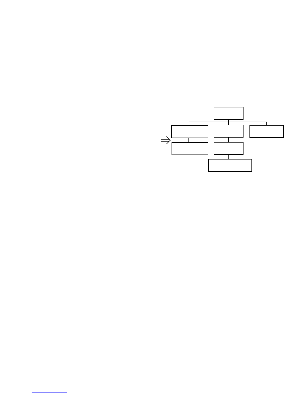
Guide to Using Harris Parts List Information
Transmitter
994 9283 001
Control Cabinet
992 9244 002
Controller Board
992 8344 002
PA Cabinet
992 9400 002
PA Amplifier
992 7894 002
PA Amplifier Board
992 7904 002
Output Cabinet
992 9450 001
The Harris Replaceable Parts List Index portrays a tree structure with the major items being leftmost in the index.
The example below shows the Transmitter as the highest item in the tree structure. If you were to look at the bill
of materials table for the Transmitter you would find the Control Cabinet, the PA Cabinet, and the Output
Cabinet. In the Replaceable Parts List Index the Control Cabinet, PA Cabinet, and Output Cabinet show up one
indentation level below the Transmitter and implies that they are used in the Transmitter. The Controller Board is
indented one level below the Control Cabinet so it will show up in the bill of material for the Control Cabinet.
The tree structure of this same index is shown to the right of the table and shows indentation level versus tree
structure level.
Example of Replaceable Parts List Index and equivalent tree structure:
Replaceable Parts List Index Part Number Page
Table 7-1. Transmitter 994 9283 001 7-2
Table 7-2. Control Cabinet 992 9244 002 7-3
Table 7-3. Controller Board 992 8344 002 7-6
Table 7-4. PA Cabinet 992 9400 002 7-7
Table 7-5. PA Amplifier 994 7894 002 7-9
Table 7-6. PA Amplifier Board 992 7904 002 7-10
Table 7-7. Output Cabinet 992 9450 001 7-12
The part number of the item is shown to the right of the description as is the page in the manual where the bill for
that part number starts. Inside the actual tables, four main headings are used:
NOTE: Inside the individual tables some standard conventions are used:
The term “SEE HIGHER LEVEL BILL” in the description column implies that the reference designated part
• Table #-#. ITEM NAME - HARRIS PART NUMBER - this line gives the information that corresponds
to the
• Replaceable Parts List Index entry;
• HARRIS P/N column gives the ten digit Harris part number (usually in ascending order);
• DESCRIPTION column gives a 25 character or less description of the part number;
• REF. SYMBOLS/EXPLANATIONS column 1) gives the reference designators for the item (i.e., C001,
R102, etc.) that corresponds to the number found in the schematics (C001 in a bill of material is equiva
lent to C1 on the schematic) or 2) gives added information or further explanation (i.e., “Used for 208V
operation only,” or “Used for HT 10LS only,” etc.).
• A # symbol in front of a component such as #C001 under the REF. SYMBOLS/EXPLANATIONS col-
umn means that this item is used on or with C001 and is not the actual part number fo r C001.
• In the ten digit part numbers, if the last three numbers are 000, the item is a part that Harris has pur-
chased and has not manufactured or modified. If the last three numbers are other than 000, the item is
either manufactured by Harris or is purchased from a vendor and modified for use in the Harris product.
• The first three digits of the ten digit part number tell which family the part num ber belongs to - for
example, all electrolytic (can) capacitors will be in the same family (524 xxxx 000). If an electrolytic
(can) capacitor is found to have a 9xx xxxx xxx part number (a number outside of the normal family of
numbers), it has probably been modified in some manner at the Harris factory and will therefore show
up farther down into the individual parts list (because each table is normally sorted in ascending order).
Most Harris made or modified assemblies will have 9xx xxxx xxx numbers associated with them.
number will show up in a bill that is higher in the tree structure. This is often the case for components
that may be frequency determinant or voltage determinant and are called out in a higher level bill
structure that is more customer dependent than the bill at a lower level.
-
12/20/11 888-2595-001 vii
WARNING: Disconnect primary power prior to servicing.

viii 888-2595-001 12/20/11
WARNING: Disconnect primary power prior to servicing.
12/20/11 888-2595-001 ix
WARNING: Disconnect primary power prior to servicing.

x 888-2595-001 12/20/11
WARNING: Disconnect primary power prior to servicing.

!
WA RN IN G:
THE CURRENTS AND VOLTAGES IN THIS EQUIPMENT ARE DANGEROUS.
!
WA RN IN G:
!
WA RN IN G:
!
WA RN IN G:
PERSONNEL MUST AT ALL TIMES OBSERVE SAFETY WARNINGS, INSTRUC
TIONS, AND REGULATIONS.
-
This manual is intended as a general guide for trained and qualified personnel who are aware
of the dangers inherent in handling potentially hazardous electrical/electronic circuits. It is not
intended to contain a complete statement of all safety precautions which should be observed
by personnel in using this or other electronic equipment.
The installation, operation, maintenance, and service of this equipment involves risks both to
personnel and equipment, and must be performed only by qualified personnel exercising due
care. HARRIS CORPORATION shall not be responsible for injury or damage resulting from
improper procedures or from the use of improperly trained or inexperienced personnel
performing such tasks. During installation and operation of this equipment, local building
codes and fire protection standards must be observed.
The following National Fire Protection Association (NFPA) standards are recommended as
reference:
- Automatic Fire Detectors, No. 72E
- Installation, Maintenance, and Use of Portable Fire Extinguishers, No. 10
- Halogenated Fire Extinguishing Agent Systems, No. 12A
ALWAYS DISCONNECT POWER BEFORE OPENING COVERS, DOORS, ENCLOSURES, GATES, PANELS, OR SHIELDS. ALWAYS USE GROUNDING STICKS
AND SHORT OUT HIGH VOLTAGE POINTS BEFORE SERVICING. NEVER MAKE
INTERNAL ADJUSTMENTS, PERFORM MAINTENANCE, OR SERVICE WHEN
ALONE OR WHEN FATIGUED.
Do not remove, short-circuit, or tamper with interlock switches on access covers, doors,
enclosures, gates, panels, or shields. Keep away from live circuits, know your equipment and
don’t take chances.
IN CASE OF EMERGENCY, ENSURE THAT POWER HAS BEEN DISCONNECTED.
IF OIL FILLED OR ELECTROLYTIC CAPACIT ORS ARE UTILIZED IN YOUR
EQUIPMENT, AND IF A LEAK OR BULGE IS APPARENT ON THE CAPACITOR
CASE WHEN THE UNIT IS OPENED FOR SERVICE OR MAINTENANCE, ALLOW
THE UNIT TO COOL DOWN BEFORE ATTEMPTING TO REMOVE THE DEFEC
TIVE CAP ACITOR. DO NOT ATTEMPT TO SERVICE A DEFECTIVE CAPACITOR
-
12/20/11 888-2595-001 xi
WARNING: Disconnect primary power prior to servicing.
WHILE IT IS HOT DUE TO THE POSSIBILITY OF A CASE RUPTURE AND SUBSEQUENT INJURY.
xii 888-2595-001 12/20/11
WARNING: Disconnect primary power prior to servicing.

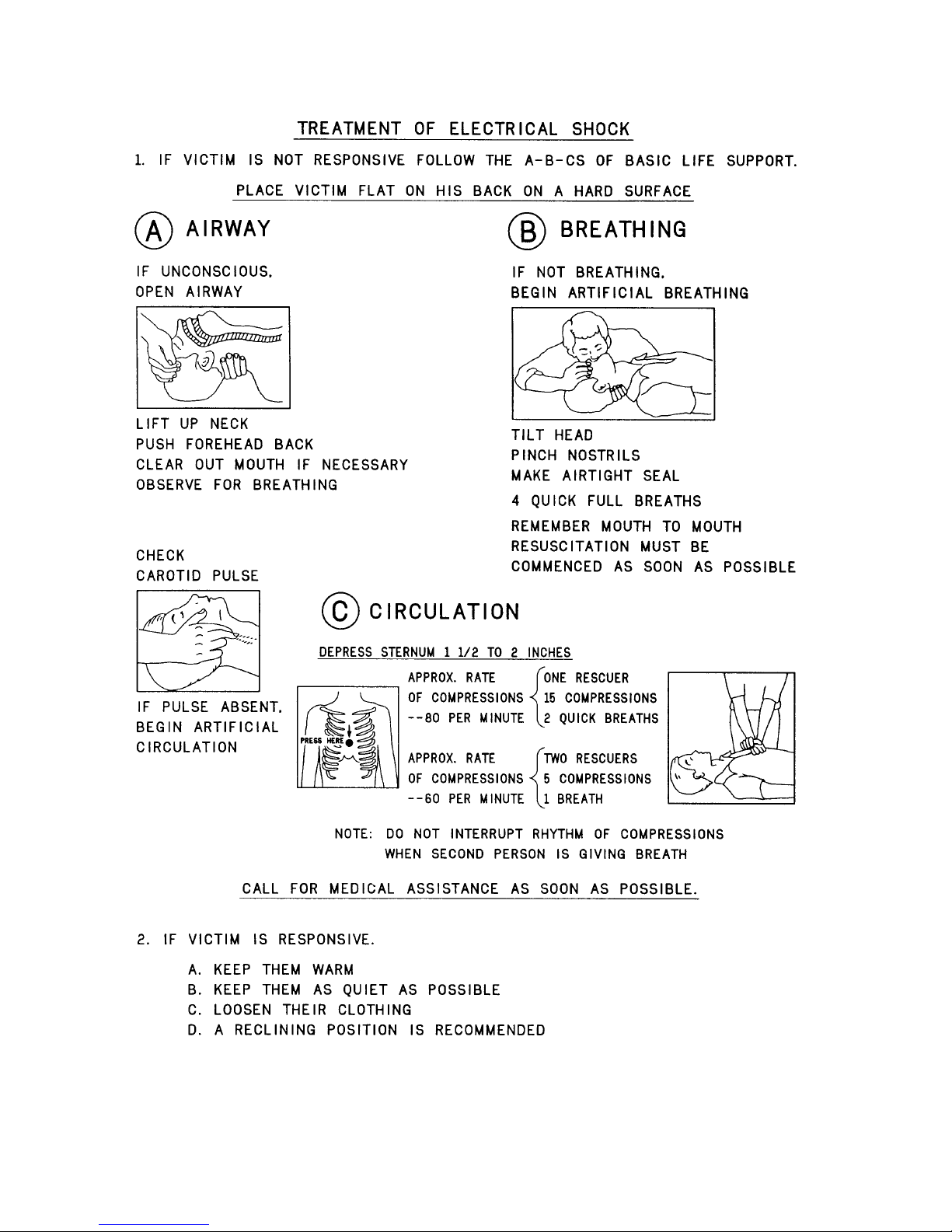
FIRST-AID
NOTE:
Personnel engaged in the installation, operation, maintenance, or servicing of this equipment
are urged to become familiar with first-aid theory and practices. The following information is
not intended to be complete first-aid procedures; it is brief and is only to be used as a
reference. It is the duty of all personnel using the equipment to be prepared to give adequate
Emergency First Aid and thereby prevent avoidable loss of life.
Treatment of Electrical Burns
1. Extensive burned and broken skin
a. Cover area with clean sheet or cloth. (Cleanest available cloth
article.)
b. Do not break blisters, remove tissue, remove adhered particles of
clothing, or apply any salve or ointment.
c. Treat victim for shock as required.
d. Arrange transportation to a hospital as quickly as possible.
e. If arms or legs are affected keep them elevated.
If medical help will not be available within an hour and the victim is conscious and
not vomiting, give him a weak solution of salt and soda: 1 level teaspoonful of salt
and 1/2 level teaspoonful of baking soda to each quart of water (neither hot or
cold). Allow victim to sip slowly about 4 ounces (a half of glass) over a period of
15 minutes. Discontinue fluid if vomiting occurs. (Do not give alcohol.)
2. Less severe burns - (1st & 2nd degree)
a. Apply cool (not ice cold) compresses using the cleanest available
cloth article.
b. Do not break blisters, remove tissue, remove adhered particles of
clothing, or apply salve or ointment.
c. Apply clean dry dressing if necessary.
d. Treat victim for shock as required.
e. Arrange transportation to a hospital as quickly as possible.
f. If arms or legs are affected keep them elevated.
REFERENCE:
ILLINOIS HEART ASSOCIATION
AMERICAN RED CROSS ST ANDARD FIRST AID AND PERSONAL SAFETY
MANUAL (SECOND EDITION)
12/20/11 888-2595-001 xiii
WARNING: Disconnect primary power prior to servicing.

xiv 888-2595-001 12/20/11
WARNING: Disconnect primary power prior to servicing.

Table of Contents
Section 1
Introduction
Manual Contents . . . . . . . . . . . . . . . . . . . . . . . . . . 1-1
Features / Benefits. . . . . . . . . . . . . . . . . . . . . . . . . 1-2
General Product Description. . . . . . . . . . . . . . . . . 1-3
Exciter. . . . . . . . . . . . . . . . . . . . . . . . . . . . . . . . . 1-3
Amplifier . . . . . . . . . . . . . . . . . . . . . . . . . . . . . . 1-4
Transmitter Nomenclature. . . . . . . . . . . . . . . . . . . 1-4
Tri-mode Operation. . . . . . . . . . . . . . . . . . . . . . . . 1-5
ZX Transmitter General Construction. . . . . . . . . . 1-5
Simplified Block Diagrams. . . . . . . . . . . . . . . . . . 1-8
Major Subassemblies. . . . . . . . . . . . . . . . . . . . . . 1-13
Transmitter Accessories . . . . . . . . . . . . . . . . . . . 1-18
Customized Rack Integration . . . . . . . . . . . . . . 1-18
AC Distribution & Signal Monitor Chassis . . . 1-18
Directional Coupler or Wattmeter . . . . . . . . . . 1-18
Dual-Drive / Main-alternate Switcher . . . . . . . 1-19
Specifications . . . . . . . . . . . . . . . . . . . . . . . . . . . 1-20
Section 2
Installation
Field Services . . . . . . . . . . . . . . . . . . . . . . . . . . . . 2-1
Installation. . . . . . . . . . . . . . . . . . . . . . . . . . . . . 2-1
Commissioning. . . . . . . . . . . . . . . . . . . . . . . . . . 2-2
Unpacking . . . . . . . . . . . . . . . . . . . . . . . . . . . . . . . 2-2
Returns and Exchanges . . . . . . . . . . . . . . . . . . . . . 2-2
Transmitter Documentation. . . . . . . . . . . . . . . . . . 2-2
Installation and Outline Drawings . . . . . . . . . . . 2-3
Site Selection. . . . . . . . . . . . . . . . . . . . . . . . . . . . . 2-3
AC Mains Requirements. . . . . . . . . . . . . . . . . . . . 2-4
Transmitters with AC Distribution Chassis. . . . 2-4
Transmitters without AC Distribution Chassis. . 2-5
Surge Suppression Devices. . . . . . . . . . . . . . . . . . 2-7
Ground Requirements . . . . . . . . . . . . . . . . . . . . . . 2-7
Overview of RF Grounding Practices . . . . . . . . 2-8
Cooling System Requirements . . . . . . . . . . . . . . . 2-9
Personnel and Equipment Protection . . . . . . . . . 2-11
Safety circuits. . . . . . . . . . . . . . . . . . . . . . . . . . 2-11
Remote Control Installation . . . . . . . . . . . . . . . . 2-12
Exciter Connections . . . . . . . . . . . . . . . . . . . . . 2-17
System Bus Connections. . . . . . . . . . . . . . . . . . . 2-20
Initial Start-up Procedure . . . . . . . . . . . . . . . . . . 2-20
Section 3
Operation
Introduction. . . . . . . . . . . . . . . . . . . . . . . . . . . . . . .3-1
Controls and Indicators. . . . . . . . . . . . . . . . . . . . . .3-1
Front Panel . . . . . . . . . . . . . . . . . . . . . . . . . . . . . .3-1
Controller board . . . . . . . . . . . . . . . . . . . . . . . . . .3-3
Internal LEDs. . . . . . . . . . . . . . . . . . . . . . . . . . . .3-6
System Metering Assembly . . . . . . . . . . . . . . . . . .3-7
Basic Operational Procedures. . . . . . . . . . . . . . . . .3-8
ON/OFF Procedure . . . . . . . . . . . . . . . . . . . . . . .3-8
Power Raise/Lower Procedure. . . . . . . . . . . . . . .3-9
Switch Operating Mode Procedure
(FlexStar HDX Exciter) . . . . . . . . . . . . . . . . . . . .3-9
Basic Functional Check Procedure . . . . . . . . . .3-10
Section 4
Theory of Operation
Introduction. . . . . . . . . . . . . . . . . . . . . . . . . . . . . . .4-1
RF Interconnect Wiring Diagram . . . . . . . . . . . . . .4-1
Output Assembly . . . . . . . . . . . . . . . . . . . . . . . . . .4 -2
AC-DC Interconnect Wiring Diagram . . . . . . . . . .4-4
PA Backplane. . . . . . . . . . . . . . . . . . . . . . . . . . . . .4-5
PA Reverse Power Alarm. . . . . . . . . . . . . . . . . . .4-5
PA Temperature Alarm. . . . . . . . . . . . . . . . . . . . .4-6
PA Current Alarm. . . . . . . . . . . . . . . . . . . . . . . . .4-6
Socket Interlock Module Fault Sensor. . . . . . . . .4-7
IPA Backplane. . . . . . . . . . . . . . . . . . . . . . . . . . . . .4-7
I/O Filter PCB. . . . . . . . . . . . . . . . . . . . . . . . . . . . .4-8
8X PS Interface PCB . . . . . . . . . . . . . . . . . . . . . . .4-9
5X Fan Monitor PCB . . . . . . . . . . . . . . . . . . . . . .4-10
16X Load PCB . . . . . . . . . . . . . . . . . . . . . . . . . . .4-11
PA, IBOC PCB . . . . . . . . . . . . . . . . . . . . . . . . . . .4-11
Transmitter Controller PCB . . . . . . . . . . . . . . . . .4-12
On/Off Control. . . . . . . . . . . . . . . . . . . . . . . . . .4-12
Auto Restart. . . . . . . . . . . . . . . . . . . . . . . . . . .4-13
APC Circuit and Power Level Adjust . . . . . . . .4-14
Operating Mode and Bias Level Control . . . . . .4-16
Metering . . . . . . . . . . . . . . . . . . . . . . . . . . . . . . .4-17
Fault and Status Signaling . . . . . . . . . . . . . . . . .4-19
Load Temperature Fault Sensor . . . . . . . . . . . . .4-20
Ambient Temperature Sensor. . . . . . . . . . . . . . .4-20
Drain Voltage Adjust . . . . . . . . . . . . . . . . . . . . .4-20
System Metering Assembly . . . . . . . . . . . . . . . . .4-20
1

Table of Contents (Continued)
System Interconnect (multi-PA chassis
transmitters). . . . . . . . . . . . . . . . . . . . . . . . . . . . . 4-21
Command Sharing. . . . . . . . . . . . . . . . . . . . . . . 4-21
Power Control Sharing . . . . . . . . . . . . . . . . . . . 4-23
Section 5
Maintenance and Alignments
Introduction . . . . . . . . . . . . . . . . . . . . . . . . . . . . . . 5-1
General Maintenance Guidelines. . . . . . . . . . . . . . 5-2
Personnel Training . . . . . . . . . . . . . . . . . . . . . . . 5-2
Recommended Tools and Equipment . . . . . . . . . 5-3
Spares Holding . . . . . . . . . . . . . . . . . . . . . . . . . . 5-5
Safety Precautions. . . . . . . . . . . . . . . . . . . . . . . . 5-5
Transmitter Logbook. . . . . . . . . . . . . . . . . . . . . . 5-6
Maintenance Logbook. . . . . . . . . . . . . . . . . . . . . 5-6
Routine Maintenance . . . . . . . . . . . . . . . . . . . . . 5-7
MTBF Estimates . . . . . . . . . . . . . . . . . . . . . . . . 5-7
Basic Maintenance Procedures . . . . . . . . . . . . . . . 5-8
Power Amplifier (PA) Module Swap
Procedure. . . . . . . . . . . . . . . . . . . . . . . . . . . . . . . 5-8
Power Supply (PS) Module Swap Procedure . . 5-10
Air Filter Replacement Procedure. . . . . . . . . . . 5-11
PA Module Cleaning Procedure . . . . . . . . . . . . 5-12
Advanced Maintenance Procedures. . . . . . . . . . . 5-13
Advanced Functional Check . . . . . . . . . . . . . . . 5-13
Forward Power Meter Calibration . . . . . . . . . . 5-16
Precision Directional Coupler . . . . . . . . . . . . 5-17
Reverse Power Meter Calibration. . . . . . . . . . . 5-18
Set Transmitter Power Level (Case 1:
internal transmitter APC control) . . . . . . . . . . . 5-19
Set Transmitter Power Level (Case 2:
exciter APC control with FlexStar HDX). . . . . 5-21
APC Setup for Multiple PA Chassis . . . . . . . . . 5-23
Set User Reverse Power Foldback Threshold
(ZX2500 / ZX3750 / ZX5000). . . . . . . . . . . . . 5-24
Set User Reverse Power Foldback Threshold
(ZX7.5, ZX10) . . . . . . . . . . . . . . . . . . . . . . . . . 5-25
Periodic Cleaning and Inspection. . . . . . . . . . . 5-26
Service one PA chassis while transmitter is
on air (ZX7.5/ZX10). . . . . . . . . . . . . . . . . . . . . 5-28
Check balance by disconnecting load
(ZX7.5/ZX10) . . . . . . . . . . . . . . . . . . . . . . . . . . 5-28
Special Part Replacement Notes . . . . . . . . . . . . . 5-30
PA Module (992-9992-041G or otherwise) . . . 5-30
PA Amplifier Assembly (PWA, PA)
(992-9992-021G or otherwise) . . . . . . . . . . . . . 5-30
PS Module (736-0445-000) . . . . . . . . . . . . . . . 5-32
Transmitter Controller PCB (901-0203-541) . . 5-33
PA Backplane PCB (901-0203-381). . . . . . . . . 5-33
IPA Backplane PCB (901-0203-581) . . . . . . . . 5-33
PS Interface PCB (901-0203-531) . . . . . . . . . . 5-33
RF Output Assembly
(971-0023-026/027/028). . . . . . . . . . . . . . . . . . 5-34
Output Assembly Ballast Load
(700-1225-000). . . . . . . . . . . . . . . . . . . . . . . . . 5-38
RF Splitter (901-0203-511/561/571) . . . . . . . . 5-39
I/O Filter PCB (901-0203-551). . . . . . . . . . . . . 5-40
Web Remote PCB (901-0203-391T) . . . . . . . . 5-40
Fan Monitor PCB (901-0203-441) . . . . . . . . . . 5-40
Cooling Fans (430-0458-000). . . . . . . . . . . . . . 5-40
Front Panel Multimeter (632-1201-000). . . . . . 5-40
AC Mains Filter
(476-0528-000 or 609-0125-000). . . . . . . . . . . 5-41
Front Panel Filter (943-5567-408) . . . . . . . . . . 5-41
2X IPA Splitter (901-0203-591) . . . . . . . . . . . . 5-41
Input 3dB Attenuator (971-0023-050) . . . . . . . 5-41
System Metering Assembly . . . . . . . . . . . . . . . 5-41
Output Combiner (3dB Hybrid) . . . . . . . . . . . . 5-41
2.5 kW RF Load . . . . . . . . . . . . . . . . . . . . . . . . 5-42
Section 6
Troubleshooting
Contacting Harris Service . . . . . . . . . . . . . . . . . . . 6-1
Troubleshooting Table. . . . . . . . . . . . . . . . . . . . . . 6-2
Section 7
Parts List
ZX5000 Replaceable Parts List. . . . . . . . . . . . . . . 7-2
ZX10 Replaceable Parts List. . . . . . . . . . . . . . . . . 7-7
Appendix A - FM Web Remote
Option
Introduction . . . . . . . . . . . . . . . . . . . . . . . . . . . . . .A-1
General Product Description. . . . . . . . . . . . . . . .A-1
Installation. . . . . . . . . . . . . . . . . . . . . . . . . . . . . . .A-3
Internet Security . . . . . . . . . . . . . . . . . . . . . . . . .A-3
2

Table of Contents
Installation Procedure. . . . . . . . . . . . . . . . . . . . . A-4
Operation. . . . . . . . . . . . . . . . . . . . . . . . . . . . . . . . A-5
Access main page . . . . . . . . . . . . . . . . . . . . . . . . A-5
Theory of Operation . . . . . . . . . . . . . . . . . . . . . . A-11
Maintenance . . . . . . . . . . . . . . . . . . . . . . . . . . . . A-12
Access Configuration Page. . . . . . . . . . . . . . . . A-12
Perform Simple Reset. . . . . . . . . . . . . . . . . . . . A-17
Perform Expert Reset . . . . . . . . . . . . . . . . . . . . A-18
Change Clock Battery. . . . . . . . . . . . . . . . . . . . A-19
Calibrate Clock Speed . . . . . . . . . . . . . . . . . . . A-20
Use Microchip Discoverer Utility . . . . . . . . . . A-20
Troubleshooting. . . . . . . . . . . . . . . . . . . . . . . . . . A-22
USB Flash Drive. . . . . . . . . . . . . . . . . . . . . . . . . A-23
3

Table of Contents (Continued)
4

ZX Series
NOTE:
Section 1
Introduction
1.1 Manual Contents
This technical manual addresses the following Harris ZX series of solid-state radio
transmitters:
• ZX2500 – 2.5 kW FM transmitter
• ZX3750 – 3.75 kW FM transmitter
• ZX5000 – 5 kW FM transmitter
1
• ZX7.5 – 7.5 kW FM transmitter
• ZX10 – 10 kW FM transmitter
This manual does not address the ZX transmitter models listed below:
• ZX500 – 500W FM transmitter
• ZX1000 – 1000W FM transmitter
• ZX2000 – 2000W FM transmitter
• ZX3500 – 3500W FM transmitter
These transmitters are addressed in Instruction Book (888-2594-001).
This manual contains the following sections:
• Section 1: Introduction, identifies the versions of the product available and the possi-
ble options.
• Section 2: Installation, details the procedures to receive, install, and commission the
transmitter for use, including an initial turn-on procedure.
12/20/11 888-2595-001 1-1
WARNING: Disconnect primary power prior to servicing.

Section 1 Introduction
• Section 3: Operation, describes operation of the equipment and is intended to be the
primary section referenced by operating personnel.
• Section 4: Theory of Operation, is included to help service personnel to understand
the inner workings of the transmitter.
• Section 5: Maintenance, lists and explains alignments and adjustments that could be
required to maintain the transmitter once in operation.
• Section 6: Troubleshooting, is included as a servicing aid to be used along with Sec-
tions 4 and 5 by qualified service personnel to identify and correct an equipment malfunction.
• Section 7: Parts List, is a comprehensive listing of the components that may be
replaced in the field.
• Appendix A: FM WEB remote option, proivdes information about the optional
WEB remote interface card.
1.2 Features / Benefits
ZX Series
The Harris ZX Series of transmitters offers the following useful features and benefits:
• HD Radio capable with on-the-fly switching between FM, FM+HD, or HD mode
when used with FlexStar exciter.
• Broadband design to eliminate tuning adjustments from 87.5 MHz through 108 MHz
(N+1 capable). Frequency change can be done electronically in seconds with MicroMax or FlexStar exciter or Digit exciter with external controller.
• Redundant hot-plug RF amplifier modules allow module replacement while transmit-
ter is in operation.
• Redundant hot-plug power supplies modules allow module replacement while trans-
mitter is in operation, including transmitter logic supplies. (each PS module has both
50V and 5V logic supplies)
• Redundant cooling fans allow transmitter to operate at full power for extended peri-
ods with a fan failure, while fan tachometer alarm notifies service personnel of failure condition.
• Three independent AC mains inputs per amplifier chassis and regulated power sup-
plies allow transmitter to accept a wide range of single or three phase mains power
without concern for line balance or rotation.
• Redundant IPA amplifiers and PA splitters eliminate a single point of failure.
• Non software-based controller for simple, repeatable operation. Does not require
UPS or battery to retain settings during AC mains failures.
• EIA rack mounting for easy installation with only 16RU height for 5000W amplifier .
1-2 888-2595-001 12/20/11
WARNING: Disconnect primary power prior to servicing.
ZX Series
(Flexstar HDX exciter shown)
[002] Amplifier
[001] Exciter
[001]
[002]
• Optional air plenum available for interface to an external ducted air system.
• Precision directional RF sample port provided for customer use.
1.3 General Product Description
The ZX series of solid state transmitters is designed to synthesize and amplify
radiofrequency signals in the FM broadcast band (87.5MHz -108MHz).
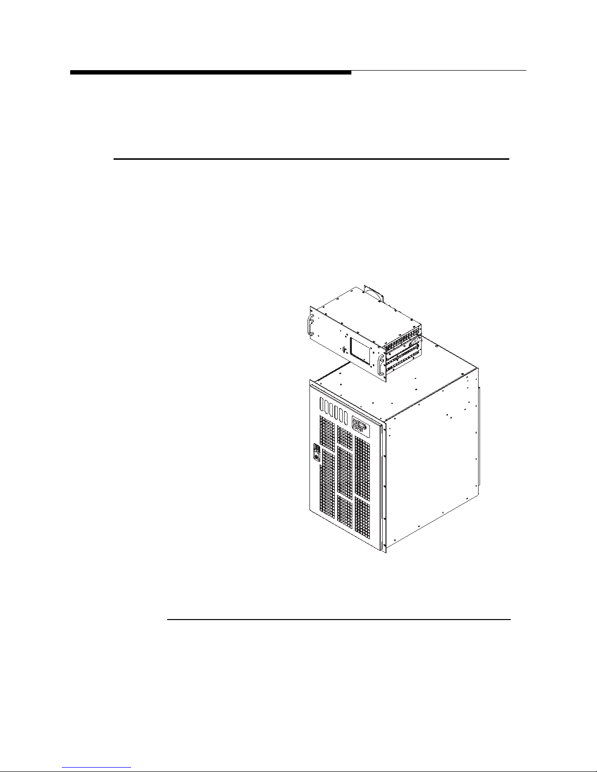
The complete ZX transmitter consists of one or more of each of two major assemblies:
an FM exciter and the ZX amplifier chassis. These are shown in Figure 1-1.
Section 1 Introduction
12/20/11 888-2595-001 1-3
1.3.1 Exciter
The exciter accepts an audio signal in either analog or digital format and modulates it
onto an RF carrier. Depending on the format of modulation, digital HD Radio or
traditional FM, the exciter may be any one of these Harris exciters:
Figure 1-1 Major subassemblies of ZX series transmitter
WARNING: Disconnect primary power prior to servicing.

Section 1 Introduction
NOTE:
• Micromax FM – FM exciter with analog modulator.
• Digit CD – Digitally synthesized FM exciter.
• FlexStar HDX - Tri-mode exciter capable of either traditional FM or digital HD
Radio transmissions.
1.3.2 Amplifier
The amplifier chassis accepts a low level on-channel RF signal from the exciter and
amplifies it to the desired output level for transmission. The transmitter models
addressed in this manual have five standard FM power levels: 2500W, 3750W, 5000W,
7.5kW & 10kW.
This manual chiefly addresses the ZX amplifier chassis and the operation of the
transmitter as a whole. A manual dedicated to the exciter is provided separately.
1.4 Transmitter Nomenclature
ZX Series
The complete ZX transmitter is named according to the particular combination of
exciter and amplifier chassis being employed. The number following the ZX prefix
indicates the full nominal FM power level,either in watts for power levels below
5000W or in kilowatts for power levels above 5000W. A suffix of FM, CD, FLX, or
HD+ is assigned according to the exciter type.
For example:
ZX5000 = 5000W amplifier with no exciter
ZX5000MX = 5000W amplifier with MicroMax
ZX5000CD = 5000W amplifier with DIGIT CD
ZX5000FLX = 5000W amplifier with FlexStar
only, no HD Radio)
ZX5000HDPL (HD plus) = 5000W amplifier with FlexStar
exciter (both FM and HD Radio capable)
FM exciter
(TM)
digital FM exciter
(TM)
HDX-FM digital FM exciter (FM
(TM)
HDX-FM digital FM
(TM)
In addition, the FlexStar exciter may have one or two RF outputs, depending on
the model number. The use of dual RF outputs is advantageous in certain appli
cations.
1-4 888-2595-001 12/20/11
WARNING: Disconnect primary power prior to servicing.
-

ZX Series
FLX-11 = single FM output
FLX-12 = dual FM outputs
HDPL-21 = single tri-mode output (FM, FM+HD, HD)
HDPL-22 = dual tri-mode outputs
1.5 Tri-mode Operation
All ZX transmitters are designed to operate in any one of three different modes:
1. FM mode = traditional FM modulation
2. FM+HD mode = hybrid mode with analog and digital HD Radio simulcast
3. HD mode = digital HD Radio modulation only
The determination of operating mode is made by the exciter. To transmit a digital HD
Radio signal, an HD Radio exciter, such as the FlexStar HDX exciter is required. The
ZX amplifier can switch on-the-fly between all three operating modes, as commanded
by the exciter through an exciter interface cable.
Section 1 Introduction
1.6 ZX Transmitter General Construction
The ZX transmitter features all solid-state construction and utilizes a series of FETbased power amplifier (PA) modules to amplify the RF signal. In addition to RF drive
power from the exciter, these PA modules utilize 50V DC power supplied by
switchmode power supply (PS) modules. Both the PA and PS modules are hotpluggable and may be inserted and removed from the transmitter while it is on the air.
12/20/11 888-2595-001 1-5
WARNING: Disconnect primary power prior to servicing.
Section 1 Introduction
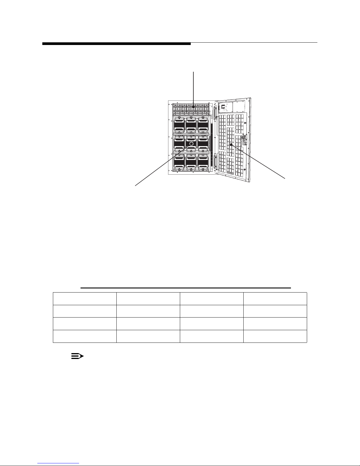
NOTE:
[101]
[102]
[103]
[101] Power supply (PS) module
[102] Front door
[103] Power amplifier (PA) module
ZX Series
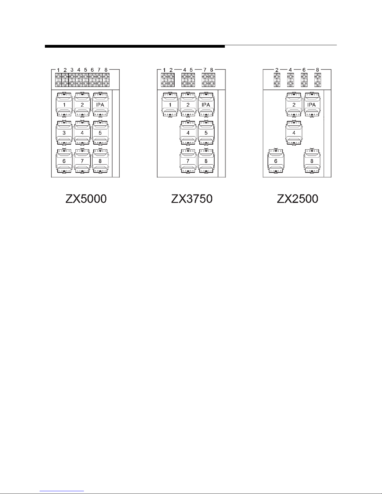
The number of PA and PS modules, size, weight, and other important parameters vary
according to the transmitter model and desired power level. Information on the number
of PA and PS modules as a function of transmitter model for power levels of 5000W
and below is given below in Table 1-1 and Figure 1-3.
Table 1-1 Complement of Modules vs Transmitter Model
Model PA Modules* PS Modules Cooling Fans
ZX5000 8 + 1 8 5
ZX3750 6 + 1 6 5
ZX2500 4 + 1 4 5
Figure 1-2 PA and PS modules in ZX series amplifier
“+1” designation indicates an IPA module: a PA module installed in the IPA position.
1-6 888-2595-001 12/20/11
WARNING: Disconnect primary power prior to servicing.
ZX Series
Section 1 Introduction
Figure 1-3 Positions of PA and PS modules in various ZX series transmitter models
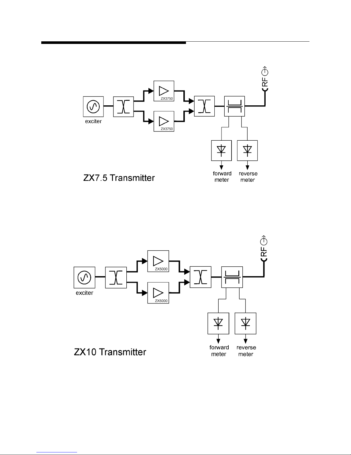
The transmitter models at 7.5kW and above are made by combining the outputs of
multiple ZX3750 or ZX5000 amplifier chassis in an integrated system. The number of
amplifier chassis per model is as follows:
ZX7.5 = 2 x ZX3750
ZX10 = 2 x ZX5000
Additional information on important transmitter parameters, such as size, weight, and
power consumption, may be found in drawing 839-8464-033 Outline Drawing, ZX
Transmitters in the drawing package accompanying this manual.
12/20/11 888-2595-001 1-7
WARNING: Disconnect primary power prior to servicing.

Section 1 Introduction
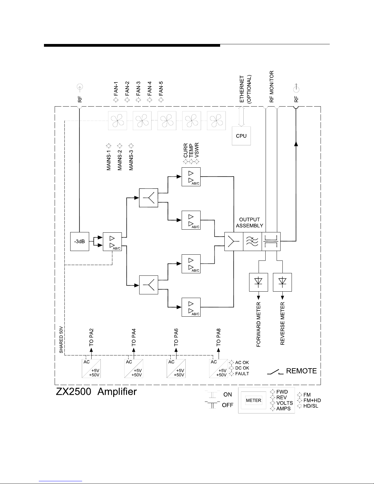
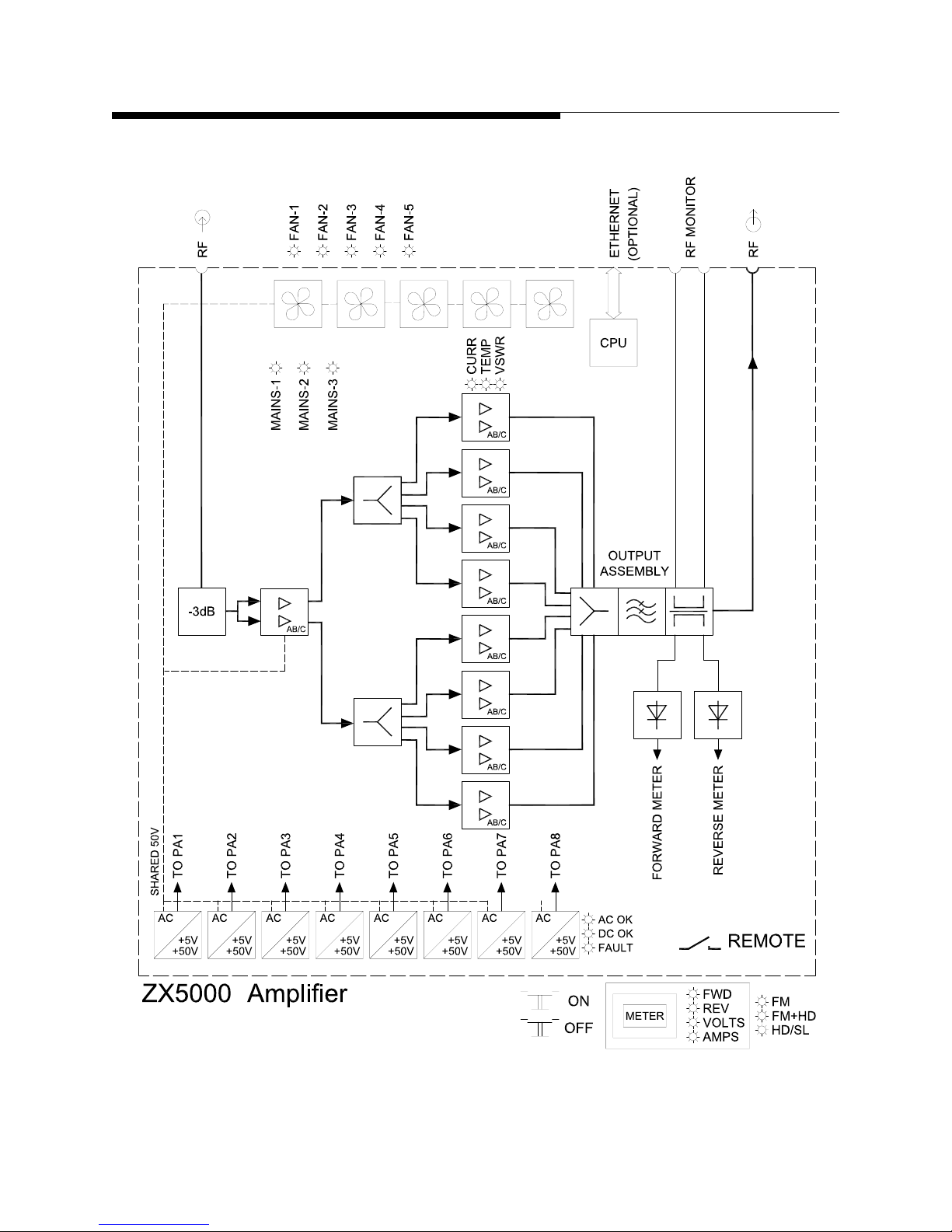
1.7 Simplified Block Diagrams
Figures 1-4 through 1-6 provide simplified block diagrams of the amplifier models
discussed in this manual. Figures 1-7 and 1-8 provide a simplified block diagram of the
ZX7.5 and ZX10 model transmitters. Consult the exciter manual for a block diagram of
the exciter.
ZX Series
1-8 888-2595-001 12/20/11
WARNING: Disconnect primary power prior to servicing.
ZX Series
Section 1 Introduction
Figure 1-4 ZX2500 amplifier simplified block diagram
12/20/11 888-2595-001 1-9
WARNING: Disconnect primary power prior to servicing.
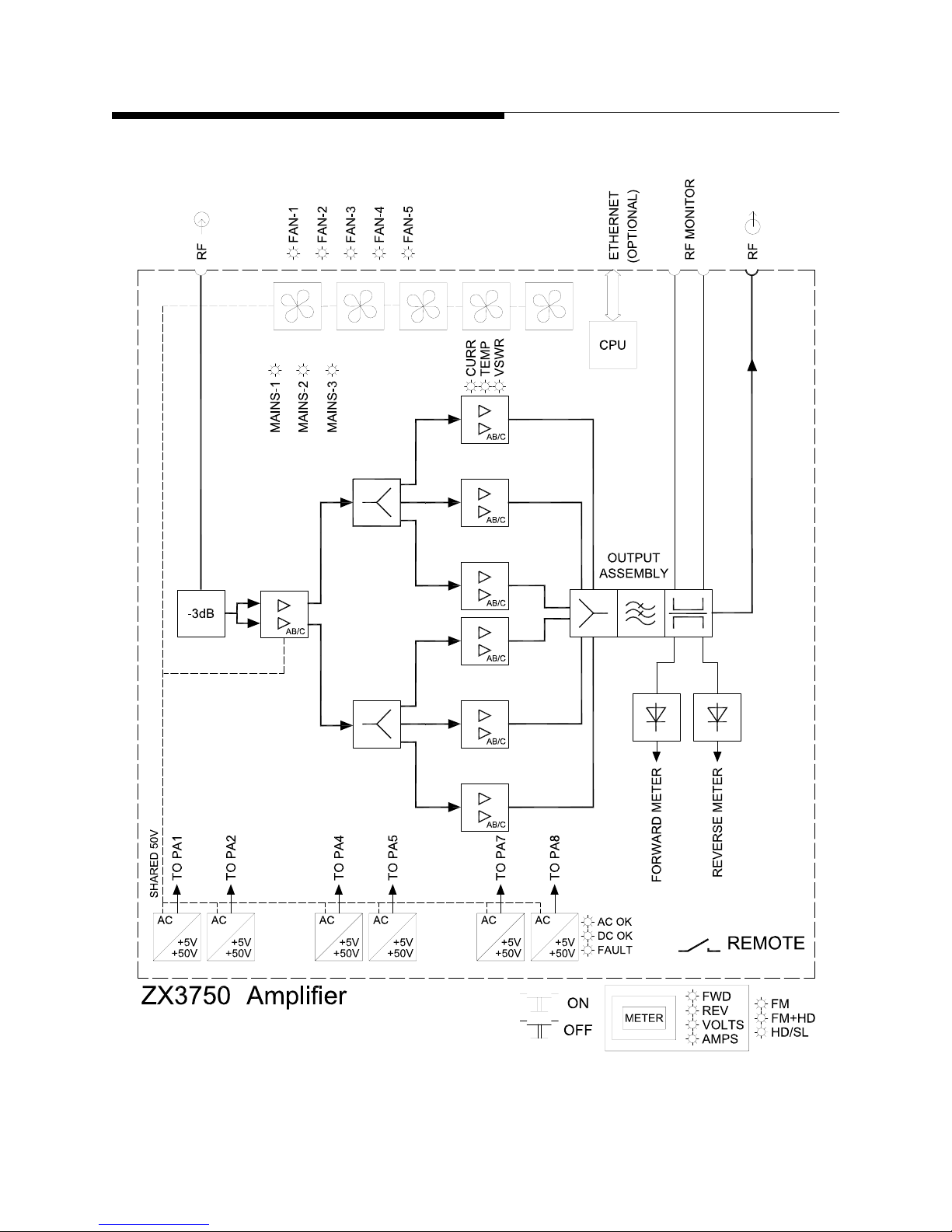
Section 1 Introduction
ZX Series
Figure 1-5 ZX3750 amplifier simplified block diagram
1-10 888-2595-001 12/20/11
WARNING: Disconnect primary power prior to servicing.
ZX Series
Section 1 Introduction
Figure 1-6 ZX5000 amplifier simplified block diagram
12/20/11 888-2595-001 1-11
WARNING: Disconnect primary power prior to servicing.
Section 1 Introduction
ZX Series
Figure 1-7 ZX7.5 similified block diagram
Figure 1-8 ZX10 simplified block diagram
1-12 888-2595-001 12/20/11
WARNING: Disconnect primary power prior to servicing.
 Loading...