

Page 1

Z3-48HD+
TECHNICAL MANUAL
888-2621-001
Z3-48HD+
T.M. No. 888-2621-001
© Copyright Harris Corporation 2007
All rights reserved
Rev. A1: Dec., 2007
Page 2

Returns And Exchanges
Damaged or undamaged equipment should not be returned unless written approval
and a Return Authorization is received from HARRIS Broadcast Communications
Division. Special shipping instructions and coding will be provided to assure proper
handling. Complete details regarding circumstances and reasons for return are to be
included in the request for return. Custom equipment or special order equipment is
not returnable. In those instances where return or exchange of equipment is at the
request of the customer, or convenience of the customer, a restocking fee will be
charged. All returns will be sent freight prepaid and properly insured by the
customer. When communicating with HARRIS Broadcast Communications
Division, specify the HARRIS Order Number or Invoice Number.
Unpacking
Carefully unpack the equipment and preform a visual inspection to determine that
no apparent damage was incurred during shipment. Retain the shipping materials
until it has been determined tha t all re ceived equipment i s not d amaged. Locate and
retain all PACKING CHECK LISTs. Use the PACKING CHECK LIST to help
locate and identify any components or assemblies which are removed for shipping
and must be reinstalled. Also remove any shipping supports, straps, and packing
materials prior to initial turn on.
Technical Assistance
HARRIS Technical and Troubleshooting assistance is available from HARRIS
Field Service during normal business hours (8:00 AM - 5:00 PM Central Time).
Emergency service is available 24 hours a day. Telephone 217/222-8200 to contact
the Field Service Department or address correspondence to Field Service
Department, HARRIS Broadcast Communications Division, P.O. Box 4290,
Quincy, Illinois 62305-4290, USA. Technical Support by e-mail:
[email protected]m. The HARRIS factory may also be contacted through a FAX
facility (217/221-7096).
Replaceable Parts Service
Replacement parts are available 24 hours a day, seven days a week from the
HARRIS Service Parts Department. Telephone 217/222-8200 to contact the service
parts department or address correspondence to Service Parts Department, HARRIS
CORPORATION, Broadcast Systems Division, P.O. Box 4290, Quincy, Illinois
62305-4290, USA. The HARRIS factory may also be contacted through a FAX
facility (217/221-7096).
NOTE:
The # symbol used in the parts list means used with (e.g. #C001 = used with C001).
ii 888-2621-001 12/5/07
WARNING: Discon nect primar y power prior to servicing.
Page 3

Manual Revision History
Z3-48HD+ Technical Manual
REV. DATE ECN Pages Affected
A Nov., 2007 Entire Manual
A1 Dec., 2007 Minor changes in Manual
12/5/07 888-2621-001 MRH-1
WARNING: Discon nect primar y power prior t o servicing .
Page 4

MRH-2 888-2621-001 12/5/07
WARNING: Discon nect primar y power prior to servicing.
Page 5
Guide to Using Har ris Parts List Information
t
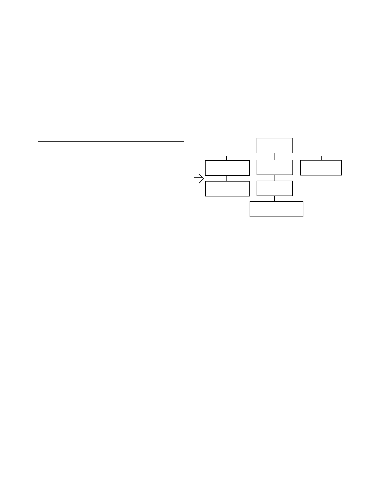
The Harris Replaceable Parts List Index portrays a tree structure with the major items being leftmost in the index. The
example below shows the Transmitter as the highest item in the tree structure. If you were to look at the bill of materials
table for the Transmitter you would find the Control Cabinet, the PA Cabinet, and the Output Cabinet. In the Replaceable
Parts List Index the Control C abinet, PA Cabinet, and Output Cabinet show up one i ndentation level b elow the T r ansmitter
and implies that they are used in the Transmitter. The Controller Board is indented one level below the Control Cabinet so
it will show up in the bill of material for the Control Cabinet. The tree structure of this same index is shown to the right of
the table and shows indentation level versus tree structure level.
Example of Replaceable Parts List Index and equivalent tree structure:
Replaceable Parts List Index Part Number Page
Table 7-1. Transmitter 994 9283 001 7-2
Table 7-2. Control Cabinet 992 9244 002 7-3
Table 7-3. Controller Board 992 8344 002 7-6
Table 7-4. PA Cabinet 992 9400 002 7-7
Table 7-5. PA Amplifier 994 7894 002 7-9
Table 7-6. PA Amplifier Board 992 7904 002 7-10
Table 7-7. Output Cabinet 992 9450 001 7-12
The part number of the item is shown to the right of the description as is the page in the manual where the bill for that part
number starts. Inside the actual tables, four main headings are used:
Control Cabinet
992 9244 002
Controller Board
992 8344 002
Transmitter
994 9283 001
PA Cabinet
992 9400 002
PA Amplifier
992 7894 002
PA Amplifier Board
992 7904 002
Output Cabine
992 9450 001
• Table #-#. ITEM NAME - HARRIS PART NUMBER - this line gives the information that corresponds to the
• Replaceable Parts List Index entry;
• HARRIS P/N column gives the ten DIGIT Harris part number (usually in ascending order);
• DESCRIPTION column gives a 25 character or less description of the part number;
• REF. SYMBOLS/EXPLANATIONS column 1) gives the reference designators for the item (i.e., C001, R102,
etc.) that corresponds to the number found in the schematics (C001 in a bill of material is equivalent to C1 on the
schematic) or 2) gives added information or further explanation (i.e., “Used for 208V operation only,” or “Used
for HT 10LS only,” etc.).
Inside the individual tables some standard conventions are used:
• A # symbol in front of a component such as #C001 under the REF. SYMBOLS/EXPLANATIONS column
means that this item is used on or with C001 and is not the actual part number for C001.
• In the ten digit part numbers , if the last th ree numbers are 000, t he item is a part that Harris has pu rchased and has
not manufactured or modified. If the last three numbers are other than 000, the item is either manufactured by
Harris or is purchased from a vendor and modified for use in the Harris product.
• The first three digits of the ten DIGIT part number tell which family the part number belongs to - for example, all
electrolytic (can) capacitors will be in the same family (524 xxxx 000). If an electrolytic (can) capacitor is found
to have a 9xx xxxx xxx part number (a number outside of the normal family of numbers), it has probably been
modified in some manner at the Harris factory and will therefore show up farther down into the individual parts
list (because each table is normally sorted in ascending order). Most Harris made or modified assemblies will
have 9xx xxxx xxx numbers associated with them.
The term “SEE HIGHER LEVEL BILL” in th e d escript ion column imp lies that the reference designated part number will
show up in a bill that is higher in the tree structure. This is often the case for components that may be
frequency determinant or voltage determinant and are called out in a higher level bill structure that is more
customer dependent than the bill at a lower level.
12/5/07 888-2621-001 v
WARNING: Discon nect primar y power prior t o servicing .
Page 6
12/5/07 888-2621-001 MRH-1
WARNING: Discon nect primar y power prior t o servicing .
Page 7

12/5/07 888-2621-001 vii
WARNING: Discon nect primar y power prior t o servicing .
Page 8

!
WARNING:
THE CURRENTS AND VOLTAGES IN THIS EQUIPMENT ARE DANGEROUS. PERSONNEL MUST AT ALL TIMES OBSERVE SAFETY WARNINGS, INSTRUCTIONS AND REGULATIONS.
This manual is intended as a general guide for trained and qualified personnel who are aware of the
dangers inherent in handling potentially hazardous electrical/electronic circuits. It is not intended to
contain a complete statement of all safety precautions which should be observed by personnel in
using this or other electronic equipment.
The installation, operation, maintenance and service of this equipment involves risks both to
personnel and equipment, and must be performed only by qualified personnel exercising due care.
HARRIS CORPORATION shall not be responsible for injury or damage resulting from improper
procedures or from the use of improperly trained or inexperienced personnel performing such tasks.
During installation and operation of this equipment, local building codes and fire protection
standards must be observed.
The following National Fire Protection Association (NFPA) standards are recommended as reference:
- Automatic Fire Detectors, No. 72E
- Installation, Maintenance, and Use of Portable Fire Extinguishers, No. 10
- Halogenated Fire Extinguishing Agent Systems, No. 12A
!
WARNING:
ALWAYS DISCONNECT POWER BEFORE OPENING COVERS, DOORS, ENCLOSURES, GATES, PANELS OR SHIELDS. ALWAYS USE GROUNDING STICKS AND
SHORT OUT HIGH VOLTAGE POINTS BEFORE SERVICING. NEVER MAKE INTERNAL
ADJUSTMENTS, PERFORM MAINTENANCE OR SERVICE WHEN ALONE OR WHEN
FATIGUED.
Do not remove, short-circuit or tamper with interlock switches on access covers, doors, enclosures,
gates, panels or shields . K e ep away from li ve circui ts , k now your equ ip ment and do n’t take chances.
!
WARNING:
IN CASE OF EMERGENCY ENSURE THAT POWER HAS BEEN DISCONNECTED.
!
WARNING:
IF OIL FILLED OR ELECTROLYTIC CAPACITORS ARE UTILIZED IN YOUR EQUIPMENT, AND IF A LEAK OR BULGE IS APPARENT ON THE CAPACITOR CASE WHEN
THE UNIT IS OPENED FOR SERVICE OR MAINTENANCE, ALLOW THE UNIT TO COOL
DOWN BEFORE ATTEMPTING TO REMOVE THE DEFECTIVE CAPACITOR. DO NOT
ATTEMPT TO SERVICE A DEFECTIVE CAPACITOR WHILE IT IS HOT DUE TO THE
POSSIBILITY OF A CASE RUPTURE AND SUBSEQUENT INJURY.
viii 888-2621-001 12/5/07
WARNING: Discon nect primar y power prior to servicing.
Page 9
12/5/07 888-2621-001 ix
WARNING: Discon nect primar y power prior t o servicing .
Page 10

FIRST-AID
Personnel engaged in the installation, operation, maintenance or servicing of this equipment
are urged to become famil iar with fi rst -aid the ory and practices. The following information is
not intended to be complete first-aid procedures, it is a brief and is only to be used as a
reference. It is the duty of all personnel using the equipment to be prepared to give adequate
Emergency First Aid and there by prevent avoidable loss of life.
Treatment of Electrical Burns
1. Extensive burned and broken skin
a. Cover area with clean sheet or cloth. (Cleanest available cloth
article.)
b. Do not break blisters, remove tissue, remove adhered particles of
clothing, or apply any salve or ointment.
c. Treat victim for shock as required.
d. Arrange transportation to a hospital as quickly as possible.
e. If arms or legs are affected keep them elevated.
NOTE:
If medical help will not be available within an hour and the victim is conscious and
not vomiting, give him a weak solution of salt and soda: 1 level teaspoonful of salt
and 1/2 level teaspoonful of baking soda to each quart of water (neither hot or
cold). Allow victim to sip slowly about 4 ounces (a half of glass) over a period of
15 minutes. Discontinue fluid if vomiting occurs. (Do not give alcohol.)
2. Less severe burns - (1st & 2nd degree)
a. Apply cool (not ice cold) compresses using the cleanest available
cloth article.
b. Do not break blisters, remove tissue, remove adhered particles of
clothing, or apply salve or ointment.
c. Apply clean dry dressing if necessary.
d. Treat victim for shock as required.
e. Arrange transportation to a hospital as quickly as possible.
f. If arms or legs are affected keep them elevated.
REFERENCE:
ILLINOIS HEART ASSOCIATION
AMERICAN RED CROSS ST ANDARD FIRST AID AND PERSONAL SAFETY
MANUAL (SECOND EDITION)
x 888-2621-001 12/5/07
WARNING: Discon nect primar y power prior to servicing.
Page 11

Table of Contents
Section I
Operator Guide
Introduction . . . . . . . . . . . . . . . . . . . . . . . . . . . . . . . . .1-1
Installation Instruction. . . . . . . . . . . . . . . . . . . . . . . . .1-3
Returns And Exchanges . . . . . . . . . . . . . . . . . . . . . .1-3
Unpacking. . . . . . . . . . . . . . . . . . . . . . . . . . . . . . . . .1-3
Installation. . . . . . . . . . . . . . . . . . . . . . . . . . . . . . . . .1-3
Transmitter Operation . . . . . . . . . . . . . . . . . . . . . . . . .1 -5
RF Metering . . . . . . . . . . . . . . . . . . . . . . . . . . . . . . .1-6
Control Functions . . . . . . . . . . . . . . . . . . . . . . . . . . . 1-9
Status Indicators . . . . . . . . . . . . . . . . . . . . . . . . . . . .1-9
Remote Control. . . . . . . . . . . . . . . . . . . . . . . . . . . .1-10
Interlock Considerations . . . . . . . . . . . . . . . . . . . . .1-10
Drive Functions. . . . . . . . . . . . . . . . . . . . . . . . . . . .1-11
HDx-FM Exciter/BoostPro Control . . . . . . . . . . . . 1-12
Alignments. . . . . . . . . . . . . . . . . . . . . . . . . . . . . . . . .1-13
Section II
Parts List
Parts List . . . . . . . . . . . . . . . . . . . . . . . . . . . . . . . . . . .2-1
WARNING: Disconnect prim ary power prior to servic ing.
888-2621-001 1
Page 12

Table of Contents
2 888-2508-001
WARNING: Disconnect primary power prior to servicing.
Page 13

Section I
Operator Guide
1.1 Introduction
This manual is to provide information regarding the Z3-48HD+ Transmitter System’s
operation. In addition to the System Controllers, other System-specific functions are
discussed. Any further site-specific functionallity will be discussed in the site-specific
data packages provided with the Z3-48HD+ Transmitter System, including the
individual Z16HD+ transmitter manuals.
The Z3-48HD+ System is made of a ZD32HD+ dual transmitter and one additional
Z16HD+ transmitter cabinet. The ZD32HD+ is made of two Z16HD+ transmitter
cabinets. Most everything in the ZD32HD+ remains as the instruction book and
drawings describe except for the Drive. There are two System Controllers in the Z3-48
system. One System Controller controls and monitors only the ZD32 (transmitters A
and B). The second System Controller controls and monitors the Z3-48 which includes
the Z16 and the ZD32.
1
NOTE:
It is important to have and study all documentation of all units involved in a Z348HD+ system prior to begining installation of this complex system.
The ZD32 consists of the two cabinets on the right hand side of the system. These are
known as transmitters A and B to keep the ZD32 documentation consistent with that of
the Z3-48 system. The extra cabinet required to make up the Z3-48 system will be on
the left and be known as transmitter C. This arrangement also keeps the RF line and
combiner arrangement to a minimum for those sites that may require equipment to go in
a small space. Both of the System Controllers will be located in a separate rack next to
the system if dual exciters and Boost amps are required. Space for the System
Controllers is not available in the transmitter for this configuration.
Operation of the Z3-48HD+ in any of several modulation format modes can be
accomplished from the FlexStar HDx-FM exciter GUI panel. See exciter manual for
further details. HD modes are only available with the FMHD22 version of the
FlexStarTM Exciter.
12/5/07 888-2621-001 1-1
WARNING: Disconnect primary power prior to servicing.
Page 14

Section I Operator Guide
There are several methods of combining the analog (FM) and digital (HD) RF to create
an IBOC signal - also known as Modulation Format - that may be used in a typical
IBOC system including a backup mode. The four modes of operation are:
FM - Analog RF only; this could be the analog backup mode in the event of a
digital failure.
FM+HD - Analog & digital (at -20dB) RF, also known as Common Combining.
HD - Digital RF only, used for Separate Combining, such as 10dB combined,
dual-feed and interleaved antenna, and dual antennas.
SLC - Analog & digital (at various ratios) RF, also known as Split-level or
Mid-level Combining.
Transmitter operation can be initiated or terminated as desired by depressing the ON
HI, ON LOW, or OFF push-buttons. All three transmitters will be commanded into the
selected mode when the Z3-48 System Controller switch is depressed.
The System Controllers also provide the necessary RF metering, common external
transmitter interlock and transmitter interfac e, and combine d transmitter re mote control
functions. APC function is retained by the individual transmitters and its RF source.
Z3-48HD+
• System Controller P/N 992-8850-005
• System Control Board
• Assembly # 992-8853-001
• PWB # 843-5293-076
• Schematic # 839-8118-181
• Display Board
• Assembly # 992-8388-005
• PWB # 843-5215-004
• Schematic # 839-8025-004
NOTE:
Parts list is in Section II.
1-2 888-2621-001 12/5/07
WARNING: Disconnect prim ary power prior to servic ing.
Page 15

Z3-48HD+
1.2 Installation Instruction
1.2.1 Returns And Exchanges
Damaged or undamaged equipment should not be returned unless a Return
Authorization is issued. When communicating with Harris Corporation, Broadcast
Division, specify the order number or invoice number. Include complete details
regarding circumstances and reasons for return in the request. Custom or special order
equipment is not returnable. In instances where return or exchange of equipment is at
the request or convenience of the customer, a restocking fee will be charged. Special
shipping instructions and coding will be provided to i nsure proper handli ng. All returns
will be sent freight prepaid and properly insured by the customer.
1.2.2 Unpacking
Carefully unpack the transmitter and save all packing material. Inspect thoroughly for
any damage incurred in shipment. Retain all PACKING CHECK LISTS to help locate
and identify any components or assemblies removed for shipping. Remove any
shipping supports, and straps prior to initial turn on.
Section I Operator Guide
Before cabinet placement takes place, it is important to determine which cabinet is
transmitter C (left side as viewed from the front), transmitter A (middle), and
transmitter B (right side). This can be determined by looking at the tags on the front of
the transmitter or matching serial numbers of the cabinet to the provided test data. The
serial numbers of the cabinets can be found on the left side wall inside the module
compartment. A typical system will have the FlexStar HDx-FM Exciter(s) in the left
cabinet.
1.2.3 Installation
NOTE:
It is important to have and study all documentation of all units involved in a Z348HD+ system prior to begining installation of this comlex system.
The cabinets may be mounted together using four Cabinet Brackets and hardware
provided with the system. The Cabinet Brackets mount between the transmitters on top
using the 3/8" hardware into threads found near the front and back of any two cabinets.
1/2" hardware is provided to bolt two cabinets together near the bottom. These holes
may be accessed inside the power supply compartments of all three cabinets. The
supply may need to be pushed forward a few inches in order to gain access to the back
hole.
12/5/07 888-2621-001 1-3
WARNING: Discon nect primar y power prior t o servicing .
Page 16

Section I Operator Guide
Several cables will be secured inside the cabinets that need routed to the other cabinets
A hole located in each cabinet is provided for cable routing between cabinets. If a hole
cap is still in place, remove cap from both cabinets for interconnecting cables. Refer to
the wiring diagrams in the System Drawing Package for wire destinations. Each wire
will be marked with a wire or cable number located near the end of each wire. After
routing, cables may be permanently attached to other existing cabling. Keep in mind
some units are mounted on slides and cables are long enough to slide out with the unit
for continuous operation.
The exciter interconnect consists of various cables. Not all of these cables are necessary
in some applications. Depending on how many exciters and what type of IBOC system,
some cables may not be needed. See drawings in the Z16 manual drawing package for
further information.
The combiners and loads are usually placed where specified by the layout diagram in
the System Drawing Package. Placement of Directional Coupler assemblies are also
specified by the layout diagram. A provided coax cable should be connected between
the System Controllers and three coupler ports each; the forward power, reflected
power, and the reject load forward power.
Z3-48HD+
The reject load’s (if provided) interlock cables should be connected. Connections for
addition station interlocks may be provided depending on the configuration of the
system. Refer to the System Drawing Package for further information.
AC connections for the transmitters are located near the top in the back left side of each
cabinet. See the Z16 manual for further information. One AC connection must be made
for the Z3-48HD+ exciter(s). This TB7 terminal block is located inside the AC input
compartment of transmitter cabinet C. This input should be on a separate AC feed in
case this transmitter’s breaker is off, the exciters can operate the remaining operating
transmitters at a reduced power level. Another AC feed must be connected to the
controller rack (if provided) or each piece of equipment if a rack is not provided. This
AC feed should again be on a separate AC feed from the transmitter in case one
transmitter breaker is off. Each Harris-made piece of equipment to be placed in an
existing rack can be operated at 120 or 240 VAC depending on the AC input card
position.
Connect transmission line between the transmitters and the combiners per the layout
supplied in the System Drawing Package. Any unequal change to the transmission line
length from transmitter to combiner will have to be adjusted for in the drive circuit.
Combiner input phasing is important for proper operation. Confirm the ports of the
4.77dB hybrid are aligned according to the markings on the combiner. This combiner is
not symmetrical so it must be connected properly. Also connect transmission line to the
reject loads. Placement of the loads and length of line to the loads is not critical. Only
transmission line for the typical layout is supplied with the system unless otherwise
specified with the order.
1-4 888-2621-001 12/5/07
WARNING: Disconnect prim ary power prior to servic ing.
Page 17

Z3-48HD+
1.3 Transmitter Operation
a. Ensure all RF connections are tight, and that all control and AC service (mains)
connections are correct and secure using the correct voltage and frequency settings.
b. Set the REMOTE/DISABLE switches on all transmitters to the REMOTE posi-
tion.
c. Start transmitter A (middle cabinet) by depressing the ON HI pushbutton on the
transmitter cabinet A. Operate transmitter at or near 100%. The ZD32 System
Controller FWD PWR should read near 25%. Press LOWER button until transmitter cabinet A FWD PWR is near 20%. Turn off transmitter cabinet A by
depressing the OFF pushbutton.
d. Start transmitter B (right side) by depressing the ON HI pushbutton on the trans-
mitter cabinet B. Operate transmitter at or near 100%. The ZD32 System Controller FWD PWR should again read near 25%. Press LOWER button until
transmitter cabinet B FWD PWR is 20%. Turn off transmitter cabinet B by
depressing the OFF pushbutton.
Section I Operator Guide
e. Start transmitter C (left side) by depressing the ON HI pushbutton on the trans-
mitter cabinet C. Operate transmitter at or near 100%. The Z3-48 System Controller FWD PWR should read near 22%. Press LOWER button until transmitter
cabinet C FWD PWR is 20%. Turn off transmitter cabinet C by depressing the
OFF pushbutton.
f. Start combined transmitter operation by depressing the ON HI pushbutton switch
on the ZD32 System Controller. Both A & B transmitters should begin operation
and be producing RF power.
g. The ZD32 System Controller FWD PWR meter should be reading near 20%.
Select the REJ PWR meter position on the ZD32 Sys tem Controller and verify its
reading is near 0%. If this reading is more than 2-3%, this may be the result of
either amplitude or phase mismatch between the two combiner inputs. Adjust the
power level 2-3% out of just one transmitter, A or B. If this minimizes the reject
power to near zero, continue on to the next step. If power fro m each transm itter is
back to the same and more than 10% reject power exists, a phase mismatch may
be adjusted by changing the physical length of W901A or W901B in the drive
circuit. Some experimentation will be required. Add or remove BNC elbow adaptors or a very short length of cable (2-6 inches) to one or the other existi ng cables
at the drive splitter SP2 outputs located in cabinet A (middle). Any reject power
may be the result of a different connection from what was originally used at the
Harris test facility. Additionally, some phase adjustment can be accomplished on
the BoostPro GUI screen. See the BoostPro documentation for more details. Usually, no adjustment of amplitude or phase will be necessary.
h. Start the third cabinet C by depressing the ON HI pushbutton on the Z3-48 Sys-
tem Controller. All three transmitters should be operating and producing power.
12/5/07 888-2621-001 1-5
WARNING: Discon nect primar y power prior t o servicing .
Page 18
Section I Operator Guide
i. The Z3-48 System Controller FWD PWR meter should be reading near 20%.
Select the REJ PWR meter position on the Z3-48 system Controller and verify its
reading is near 0%. If this reading is more than 2-3%, this again may be the result
of either amplitude or phase mismatch between the two combiner inputs to the
4.77dB combiner. Adjust the power level 2-3% out of just transmitter C. If this
minimizes the reject power to near zero, continue on to the next step. If power
from each transmitter is back to the same or more than 10% reject power exists, a
phase mismatch may be adjusted by changing the physical length of W900 in the
drive circuit. Some experimentati on will be required. Add or re move BNC elbow
adaptors or a very short length of cable (2-6 inches) to W900 at the transmitter C
Exciter Switch board output. Reject power may be the result of a different connection from what was originally used at the Harris test facility. Usually, no
adjustment of amplitude of phase will be necessary.
j. Once reject power is down below 5% on both System Controllers, raise power in
all three transmitters to 100% watching that reject power does not exceed 10%. If
any reject power exists, repeat the above steps for adjustment of amplitude or
phase of all combiner inputs. Some fluctuation of power will be noticed due to
the type of detection used for an IBOC signal and its peaks.
Z3-48HD+
k. Select the RFL PWR position on the transmitters and the Sys tem Controlle rs and
verify that they all read at or near 1.01VSWR.
l. Depress the LOW ON push-button switch on both System Controllers and verify
that all transmitter output levels drop to approximately 50% and that the System
Controllers also indicate near 50% in the FWD PWR positions.
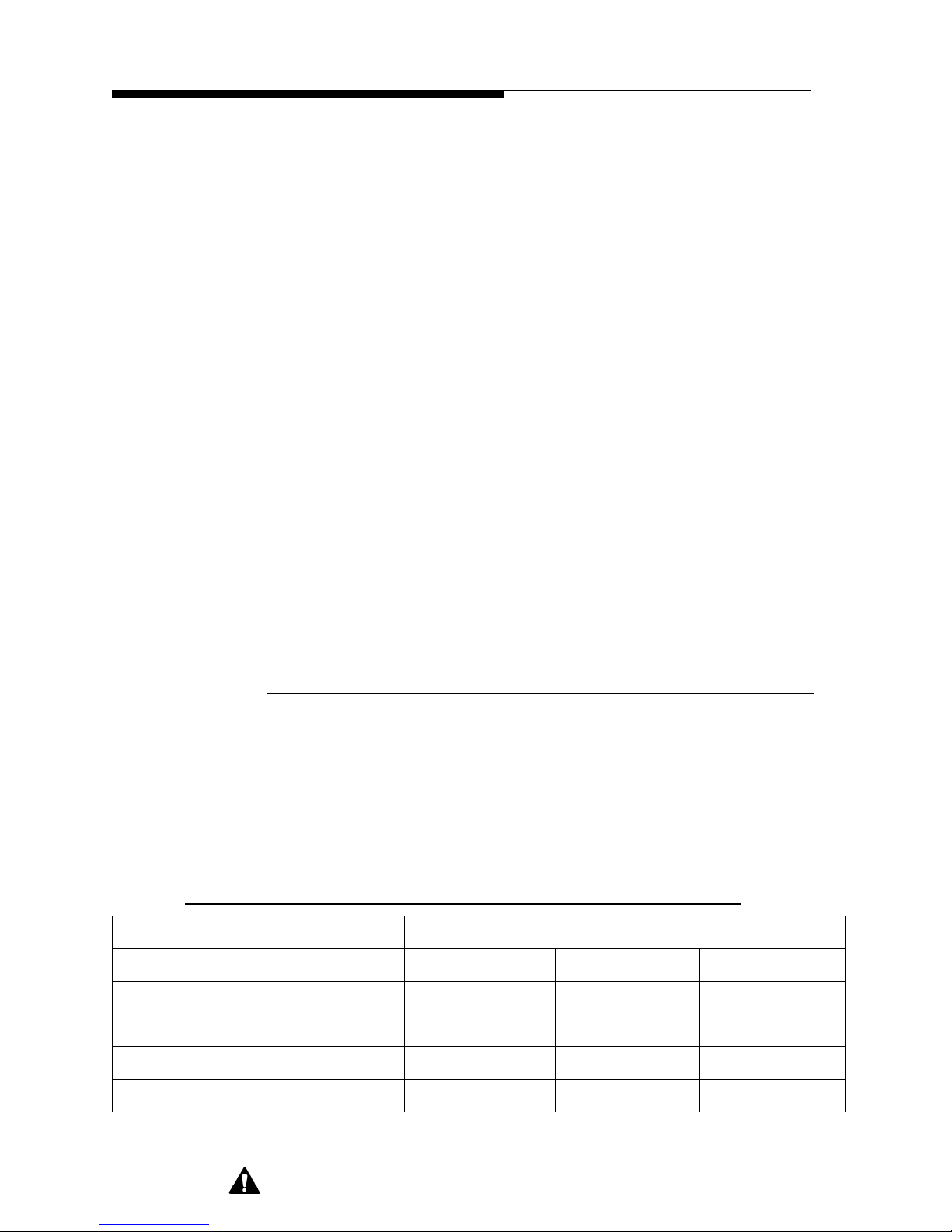
1.3.1 RF Metering
Three metering functions are provided by each System Controller. They are: Forward
output power in percent of allowed forward power (FWD PWR); reflected power
displayed as load VSWR (RFL PWR); and combiner reject load power in percent of
normal (REJ PWR). Below are the approximate values of the normal average RF levels
for a Z3-48HD+ combined transmitter system calibrated at full output in the combined
mode. See Table 1-1.
Table 1-1 System Controller Average Power Metering
Indication
FWD PWR 100% RFL PWR 1.00 REJ PWR 100%
Z3-48 System Controller
1-6 888-2621-001 12/5/07
WARNING: Disconnect prim ary power prior to servic ing.
FM+HD 21kW As Indicated 4.67kW
HD only 10.5kW As Indicated 2.33kW
FM only 30 kW As Indicated 6.67kW
Page 19

Z3-48HD+
P
2
Table 1-1 System Controller Average Power Metering
ZD32 System Controller
A REJ PWR reading of 100% will be one-fourth the total output power when the 3 dB
hybrid combiner is used, such as with the ZD32 System Controller. The REJ PWR
reading of 100% will be set for 2/3 the total output power from one transmitter when the
4.77dB hybrid combiner is used such as with the Z3-48 System Controller. Up to 2/3 of
the power from transmitter C or 1/3 of the power from the ZD32 could be present at the
4.77dB reject load. See Table 1-2 on page 1-8 for power results when one or two
transmitters are OFF. When a backup mode is used, consideration must be given to the
maximum power in the reje ct load a llowed by the overload and the maximum power the
load is capable of. As a result of this consideration, some variations from the chart exist
and are noted in the Factory Test Data Sheet.
Section I Operator Guide
FM+HD 14 kW As Indicated 3.5kW
HD only 7kW A s Indicated 1.75kW
FM only 20kW As Indicated 5kW
The following formula can be used for calculating expected power results at the antenna
port given different power level inputs as in the last two columns of Table 1-2:
P1 P2 P3++()
-----------------------------------------------------
out
=
3
where P1, P2, and P3 are the power levels from each transmitter.
Below is an Expected Power Results for Failure Conditions table.
12/5/07 888-2621-001 1-7
WARNING: Discon nect primar y power prior t o servicing .
Page 20
Section I Operator Guide
r
r
r
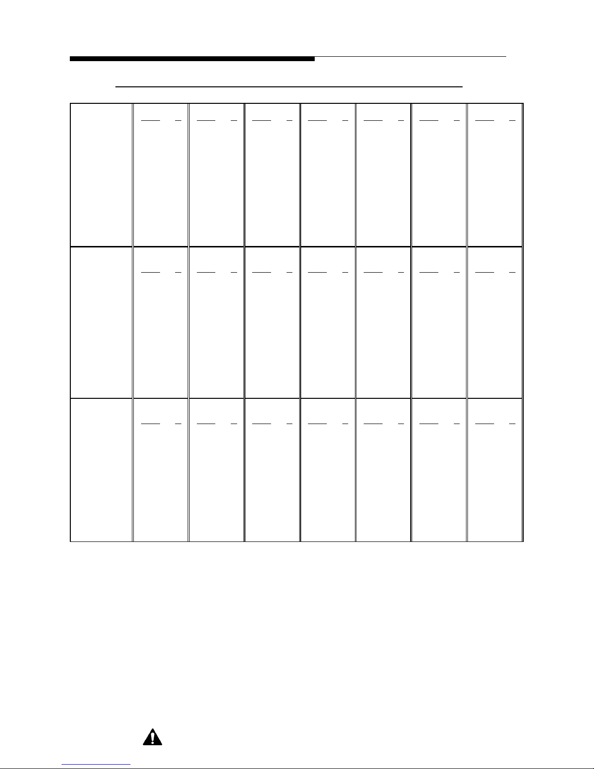
Table 1-2 Expected Power Results for Failure Conditions
Z3-48HD+
FM + HD
TX C 7kW 100 7kW 100 0 0 7kW 100 0 0 7kW 100 3.5kW 50
TX A 7kW 100 0 0 7kW 100 0 0 0 0 3.5kW 50 7kW 100
TX B 7kW 100 7kW 100 7kW 100 0 0 7kW 100 7kW 100 7kW 100
Z3-48 System
FWD 21kW 100 9.33kW 44 9.33kW 44 2.33kW 11 2.33kW 11 17.1kW 81 17.1kW 81
REJ 0 0 1.17kW 25 4.67kW 100 4.67kW 100 1.17kW 25 0.1kW 2 0.4kW 8
ZD32(A/B) System
FWD 14kW 100 3.5kW 25 14kW 100 0 0 3.5kW 25 10.2kW 72 14kW 100
REJ 0 0 3.5kW 100 00003.5kW 100 0.3kW 8 0 0
HD Only
TX C 3.5kW 100 3.5kW 100 0 0 3.5kW 100 0 0 3.5kW 100 1.75kW 50
TX A 3.5kW 100 0 0 3.5kW 100 0 0 0 0 1.75kW 50 3.5kW 100
TX B 3.5kW 100 3.5kW 100 3.5kW 100 0 0 3.5kW 100 3.5kW 100 3.5kW 100
Z3-48 System
FWD 10.5kW 100 4.67kW 44 4.67kW 44 1.17kW 11 1.67kW 11 8.55kW 81 8.54kW 81
REJ 0 0 0.58kW 25 2.33kW 100 2.33kW 100 0.58kW 25 0.05kW 2 0.2kW 8
ZD32(A/B) System
FWD 7kW 100 1.75kW 25 7kW 100 0 0 1.75kW 25 5.1kW 72 7kW 100
REJ 0 0 1.75kW 100 00001.75kW 100 0.15kW 8 0 0
Full Operation One TX OFF One TX OFF Two TX OFF
Power % Power % Power % Power % Power % Power % Power %
Full Operation One TX OFF One TX OFF Two TX OFF Two TX OFF One TX ½ Power One TX ½ Powe
Power % Power % Power % Power % Power % Power % Power %
Two TX OFF One TX ½ Power One TX ½ Powe
FM Only
TX C 10kW 100 10kW 100 0 0 10kW 100 0 0 10kW 100 5kW 50
TX A 10kW 100 0 0 10kW 100 0 0 0 0 5kW 50 10kW 100
TX B 10kW 100 10kW 100 10kW 100 0 0 10kW 100 10kW 100 10kW 100
Z3-48 System
FWD 30kW 100 13.33kW 44 13.33kW 44 3.33kW 11 3.33kW 11 24.4kW 81 24.4kW 81
REJ 0 0 1.67kW 25 6.67kW 100 6.67kW 100 1.67kW 25 0.14kW 2 0.57kW 8
ZD32(A/B) System
FWD 20kW 100 5kW 25 20kW 100 0 0 5 25 14.57kW 72 20kW 100
REJ005kW100000051000.43kW 8 0 0
The System Controllers each display values of the selected functions on a 3-1/2” digit
panel meter. Three momentary pushbutton switches allow selection of the metering
mode for the System Controller. A momentary depression of one of the three meter
select switches will put the digital metering system into the desired mode. The meter
will remain in that selected mode until another metering selection pushbutton switch is
depressed. Following an AC power interrupti on the metering system will automatically
power on in the FWD PWR mode, displaying the forward output power level, in
percent of normal.
Full Operation One TX OFF One TX OFF Two TX OFF Two TX OFF One TX ½ Power One TX ½ Powe
Power % Power % Power % Power % Power % Power % Power %
1-8 888-2621-001 12/5/07
WARNING: Disconnect prim ary power prior to servic ing.
Page 21

Z3-48HD+
Section I Operator Guide
1.3.2 Control Functions
Three momentary push-button switches allow system ON and OFF control functions to
be exercised from the front of the System Controllers. These pushbuttons are: OFF, ON
HI, and ON LOW. Depressing one of these three pushbutton switches will
simultaneously command both transmitters controlled by that System Controller into
the selected ON mode, or will return both transmitters controlled by that System
Controller to the OFF mode simultaneously.
Three LEDs indicate actual transmitter status, LOW, HI and OFF. The indicators are
controlled by the transmitter status outputs of both transmitters controlled by that
System Controller.
NOTE:
In order for these System Controller commands to be accepted by the individual
transmitter control units, the REMOTE/DISABLE switches on each individual
transmitter MUST be in the REMOTE position; or red LED off.
1.3.3 Status Indicators
The System Controllers each incorporate four LED status indicators to provide
important information about the operation conditions of the combined transmitter
system controlled by that System Controller. These indicators are RF POWER, SWR,
EXT INTERLOCK, and REJ LOAD.
The RF POWER indicator illuminates red if the system is in operation and the forward
output power level at the combiner output drops below a preset level, usually 90%. The
indicator will extinguish if the level rises above the preset level or the system is turned
off.
The SWR FAULT LED indicator will illuminate if the reflected RF power level at the
combiner output rises above a preset level, 1.3:1. If this level has been exceeded, the
LED will illuminate. The System Controller takes no action but the transmitters
themselves will either foldback or turn off depending on the level of VSWR. The
indicator will extinguish with the next System Controller ON command.
The EXT INTLK LED indicator will illuminate if the connection between J1-6 and J125 is broken. System operation, controlled by that System Controller , will automatically
be terminated and returned to the OFF state. Once the connection between J1-6 and J125 is restored, an ON command is required to restore operation. These connections are
routed through the Reject Load interlock terminals. The 5kW load interlock is
connected to the ZD32 System Controller. The 10kW load interlock is connected to the
Z3-48 System Controller.
12/5/07 888-2621-001 1-9
WARNING: Discon nect primar y power prior t o servicing .
Page 22

Section I Operator Guide
The REJ LOAD LED indicator is actually two indicators in one. One half of the
indicator is an amber LED, the other is a red LED. If the RF power delivered to the
combiner reject load associated with that System Controller exceeds a preset warning
level, usually 90%, the amber portion of the LED will illuminate. It will remain
illuminated until the RF leve l drops below the pr eset level. If the RF power deli vered to
the reject load associated with that System Controller exceeds the safe operation level
for the load, the System Controller will te rminate ope ration of the transmitt ers that feed
that particular load and the red portion of the REJ LOAD will be illuminated. It will
remain illuminated until the next ON command of that particular System Controller is
exercised.
1.3.4 Remote Control
The REMOTE/LOCAL push-button switch on the front panel of the System Controllers
allow the operator to determine if the unit will accept remote system level ON or OFF
commands. In the LOCAL mode (red LED illuminated) only the front panel switches
on the System Controller may be used to turn the system on or off. For normal
operation, the ZD32 System Controller should always remain in the REMOTE mode as
the Z3-48 System Controller uses the ZD32 remote inputs to control that portion of the
system.
Z3-48HD+
Remote system level commands, status and metering functions are available at J1 and
J11 on the System Controller. System commands are active when the REMOTE/
LOCAL switch on the front of the System Controller is in the REMOTE position.
Status and metering information is always available at J1 and J11 regardless of the
position of the REMOTE/LOCAL switch.
Table 1-10 on page 1-17, System Controller Remote Connections, gives details of the
commands, status and metering functions available at J1 and J11 on the rear of both
System Controllers. It is recommended that J1 be used only for fail-safe/interlock and
J11 be connected to a remote control (if used) for remote metering, status, and
commands.
1.3.5 Interlock Considerations
In a hybrid combiner system, if the reject presents an open interlock, both transmitters
associated with that System Controller will be interlocked off. Once the interlock is
closed, an ON command is required to restore normal operation. The interlocks are
routed through the Reject Load interlock terminals. The 5kW load interlock is
connected to the ZD32 System Controller. The 10kW load interlock is connected to the
Z3-48 System Controller. Additional devises can be wired in series with the load
interlocks if required.
1-10 888-2621-001 12/5/07
WARNING: Disconnect prim ary power prior to servic ing.
Page 23

Z3-48HD+
Section I Operator Guide
1.3.6 Drive Functions
Exciter muting and main/alternate functions are controlled by transmitter C of the Z348HD+. This is the cabinet on the left in a typical layout.
Exciter Main/Alternate control can be accessed through the transmitter C controller
LCD display screen. From HOME, press STATUS/MORE/EXCITER/SWITCH.
Observe status ON indicators for exciter 1 or exciter 2.
For exciter main/alternate operation, all exciters’ AC should be on at all times
regardless if a TX is shut down. This is accomplished by a separate AC feed for
transmitters and exciter(s). Transmitter C contains a separate AC input for the exciters.
The System Controller should also operate from a separate AC feed from the
transmitters. The System Controllers are usually located in a separate rack with a
separate AC feed.
When transmitter C is turned on, the power supply starts to ramp up and as soon as it is
at full voltage, the mute line is pulled low by an open collector output and un-mutes the
on air exciter as determined by transmi tter C. The Auxiliary output of the Flexstar HDxFM exciter is always ON (un-muted) and operating in the mode established within the
exciter . This signal is routed through t he transmitter C Exciter Switc h Board to a splitter
SP2 located in transmitter A (center cabinet). The outputs of this splitter go to the inputs
of the Exciter Switch Boards in transmitter A and transmitter B. If two Boost Pro
amplifiers are used in each transmitter A and transmitter B, the signal is switched
between the two Boost Pro inputs by the Exciter Switch Boards. The Exciter Switch
Board also controls the output of each Boost Pro by selecting the on air Boost Pro’s
output and routing it to the transmitter IPA stages. If only one Boost Pro is in each
transmitter, the controller of that transmitter will be set for only one RF source through
the LCD display screen and the Exciter Switch Board will not switch.
If during operation, the on air exciter fails, a ten second window exists to allow the
exciter to retry and come back on line by itself. If after 10 seconds power still does not
exist, a command from transmitter C Life Support Board swit ches the exciter outputs t o
the backup exciter, restoring RF drive to all transmitters.
If transmitter C is turned OFF and should a failure occur in the on air exciter, automatic
switching of the exciter’s auxiliary output will not occur but will continue to try to use
the Auxiliary output from the exciter that was on air. When transmitter C is turned back
ON, automatic switching will make the switch. If a long term OFF state is expected on
transmitter C, the auxiliary outputs can be manually changed for RF drive to
transmitters A and B. If power is re moved from transm itter C, the Exci ter Switch Board
will switch back to exciter 1 outputs but still using the always on auxiliary output.
Should the backup exciter’s auxiliary output be needed to keep transmitter A and B
operating, a manual change will be required as described earlier.
12/5/07 888-2621-001 1-11
WARNING: Discon nect primar y power prior t o servicing .
Page 24

Section I Operator Guide
In this system, the HDx-FM Exciter's AUX output is used to drive the BoostPro boost
amplifier(s) in the other TX cabinet. Phase of this drive will be shifted within the
BoostPro and there are Phase adjustments in the BoostPro. If there is a phase delay
beyond what these two adjustments can compensate for, some line length adjustment
may be necessary for proper transmitter output phasing. See Z16 manual for more
information. As discussed earlier, W901A and W901B length can be changed or BNC
elbow adapters can be removed or added inline.
!
CAUTION:
CARE SHOULD BE TAKEN NEVER TO REPLACE THESE CABLES WITH AN
UNKNOWN CABLE, POSSIBLY CAUSING FULL COMBINED TRANSMITTER
POWER OUTPUT TO GO TO A COMBINER REJECT LOAD ONLY DESIGNED
TO CARRY QUARTER TOTAL POWER.
1.3.7 HDx-FM Exciter/BoostPro Control
Z3-48HD+
The Forward Power sample of each RF source is routed directly to the transmitter
controlling each RF source(s). The transmitter will use these samples to determine if
there is an RF source failure. The sample(s) are also used to display power on the LCD
display screen.
Mute and Active signals for the Flexstar exciter(s) are exclusively controlled by
transmitter C and come from the Life Support Board. The active signal is used for the
exciters to know which one should be the on air exciter and is determined from the
display inputs, input signals, and internal logic. A high on the active line indicates
exciter 1 should be the on air exciter. If the active line is pulled low, exciter 2 will now
be the on air exciter. The mute signal routed to the exciter(s) turns off the main RF
output only as dictated by the exciter setup for this Z3-48 system. The auxiliary output
remains on at all times to provide drive to the other parts of the system, specifically
transmitter A and B.
1-12 888-2621-001 12/5/07
WARNING: Disconnect prim ary power prior to servic ing.
Page 25
Z3-48HD+
1.4 Alignments
NOTE:
All adjustments required have been made at the factory using calibrated test loads
and power meters to verify operating power levels. The following alignments are
to be performed only in the event of a field replacement involving any of these
components.
Three RF to DC sample transducers, in conjunction with RF directional couplers, are
used in each system, ZD32 and Z3-48, to monitor the RF power levels in that system.
The DC samples are routed through coaxial cables to the input jacks on the back of the
System Controllers.
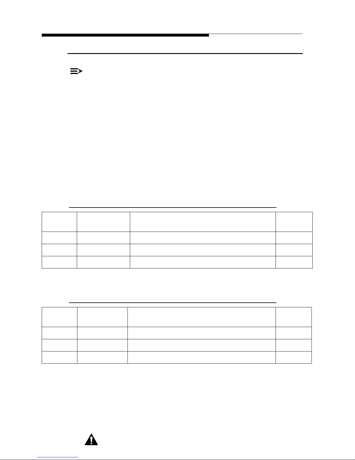
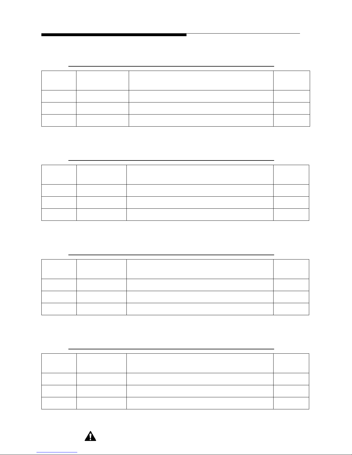
The linearizer test point voltages are initially set using the tables below as determined
by the type of system with adjustments made using the corresponding sample
calibration pot (R37, R45 or R78). Variation of these voltages will exist depending on
desired high power output and linearity of circuit.
Section I Operator Guide
Table 1-3 ZD32 System Controller: FM+HD Mode
TEST
POINT
TP2 0.275 Volts 14kW of system forward power R37
TP3 0.075 Volts 560 Watts of simulated reflected power R45
TP4 0.275 Volts 100% of reject power; 3.5kW R78
TARGET
VOLTAGE
SET UP CONDITION SAMPLE
Table 1-4 ZD32 System Controller: HD Only Mode
TEST
POINT
TP2 0.275 Vo lts 7kW of system forward power R37
TP3 0.075 Volts 280 Watts of simulated reflected power R45
TP4 0.275 Volts 100% of reject power; 1.75kW R78
TARGET
VOL TAGE
SET UP CONDITION SAMPLE
CAL
CAL
12/5/07 888-2621-001 1-13
WARNING: Discon nect primar y power prior t o servicing .
Page 26
Section I Operator Guide
Table 1-5 ZD32 System Controller: FM Only Mode
Z3-48HD+
TEST
POINT
TP2 0.275 Volts 20kW of system forward power R37
TP3 0.075 Volts 800 Watts of simulated reflected power R45
TP4 0.275 Volts 100% of reject power; 5kW R78
TARGET
VOLTAGE
SET UP CONDITION SAMPLE
Table 1-6 Z3-48HD+ System Controller: FM+HD Mode
TEST
POINT
TP2 0.275 Volts 21kW of system forward power R37
TP3 0.075 Volts 840 Watts of simulated reflected power R45
TP4 0.275 Volts 100% of reject power; 4.67kW R78
TARGET
VOL TAGE
SET UP CONDITION SAMPLE
CAL
CAL
Table 1-7 Z3-48HD+ System Controller: HD Only Mode
TEST
POINT
TP2 0.275 Volts 10.5kW of system forward power R37
TP3 0.075 Volts 420 Watts of simulated reflected power R45
TP4 0.275 Volts 100% of reject power; 2.33kW R78
TARGET
VOL TAGE
SET UP CONDITION SAMPLE
Table 1-8 Z3-48HD+ System Controller: FM Only Mode
TEST
POINT
TP2 0.275 Volts 30kW of system forward power R37
TP3 0.075 Volts 1200 Watts of simulated reflected power R45
TP4 0.275 Volts 100% of reject power; 6.67kW R78
TARGET
VOL TAGE
SET UP CONDITION SAMPLE
CAL
CAL
1-14 888-2621-001 12/5/07
WARNING: Disconnect prim ary power prior to servic ing.
Page 27
Z3-48HD+
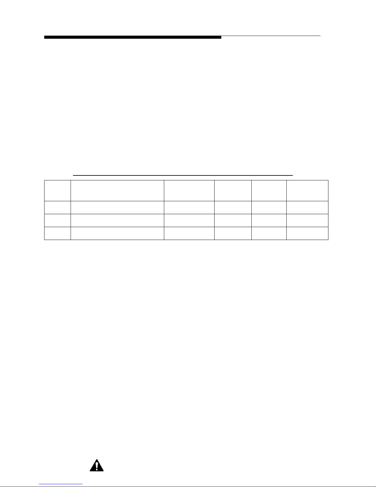
T o set t he forward power metering calibration, set the transmitters as follows (see Table
1-9 on page 1-15):
Section I Operator Guide
• Set transmitter system (only those controlled by that particular System
Controller) to operate at 100% of normal operating power (not necessarily
full power capability).
• Adjust R88, FWD PWR CAL, for 100% forward power reading on the front
panel. Some fluctuation of power will be noticed due to this type of detection
used for an IBOC signal and its peaks.
• Set transmitter power to zero and adjust R90, FWD PWR METER ZERO,
for a reading of 0%.
• Repeat previous steps as needed.
Table 1-9 System Controller RF Metering Inputs
JACK PURPOSE LINEARIZER
TEST POINT
J6 System Forward Power TP2 R37 R88 R90
J7 System Reflected Power TP3 R45 N/A R132
J8 System Reject Load Power TP4 R78 R80 R70
To set the reject power metering calibration, set the transmitters as follows:
SAMPLE
CAL
METER
CAL
METER
ZERO
• For a particular System Controller, turn ON only the transmitters needed to
run maximum power into the Reject Load. See table 1-2 for configuration of
maximum Reject Load power.
• Adjust R80, REJ PWR CAL, for a 100% reject power reading.
• Turn the transmitter power output to zero and adjust R70, REJ PWR
METER ZERO, for a reading of 0%. Repeat as needed until both conditions
are met.
To set the reflected power meter calibration and overload:
• Adjust each transmitter (only those controlled by that particular System
Controller) to operate at a forward power of half the stated reflected power
in tables above so that the system combined power is the stated reflected
power from the appropriate table. If total power output (100% forward
power) is different than stated in table, set transmitter for 0.04 times total
power out. Adjust target voltage proportionally.
12/5/07 888-2621-001 1-15
WARNING: Discon nect primar y power prior t o servicing .
Page 28

Section I Operator Guide
• Reverse the reflected power coupler on the appropriate combiner output by
loosening the hose clamps holding it to the transmission line and reattaching
it to the line in its reverse position. This must be done without disassembling
the coupler itself.
• Use R45, R FL PWR SAMPL CAL, to set test point TP3 voltage to the target
voltage in tables above. Return the coupler to its original position.
• Adjust R132, VSWR ZERO, to read 1.01 reflected power on the front panel
while the system is operating at full power and operating with no reflected
power. Removi ng the sample cable from the System C ontroller input J7 wi ll
assure no reflected power reading.
• Verify the VSWR metering circuit by operating system at full power and
forcing TP3 to read the target voltage from the tables with an external DC
voltage source connected to J7.
• Verify that the VSWR reading is 1.50:1.
• Set the system controller VSWR trip threshold with R158, SWR TRIP SET,
to trip at a VSWR of 1.30:1.
• Remove external DC voltage source and reconnect sample input cable to J7
of System Controller.
Z3-48HD+
To set other overloads and set points:
• Turn the system output power (only that controlled by the particular System
Controller) to 90% and adjust R197, LO RF TRIP SET, until the low power
LED just turns on. Raise and lower the power above and below 90% and
verify the LED comes on at the 90% point, adjust as needed.
• Using an external voltage source connected to J8 of the System Controller;
force the reject power meter to read 90% and set R161, REJ PWR
WARNING SET, until the reject warning LED comes on.
• Set the reject power meter to read 104% with an external voltage source and
adjust R169, REJ PWR TRIP SET, until transmitters receive an OFF
command. If back-up modes of operation are used, the REJ PWR TRIP SET
can be set for up to the rating of the load. A ZD32 reject load typically has a
rating 5KW but for example, the FM+HD mode, 3.5KW is the most power
this load will absorb. If FM only was the backup mode, the trip set could be
at 5KW divided by 3.5KW or 143%. See test data sheets for the set point as
done in the factory.
• Remove external DC voltage source and reconnect sample input cable to J8
of System Controller.
1-16 888-2621-001 12/5/07
WARNING: Disconnect prim ary power prior to servic ing.
Page 29
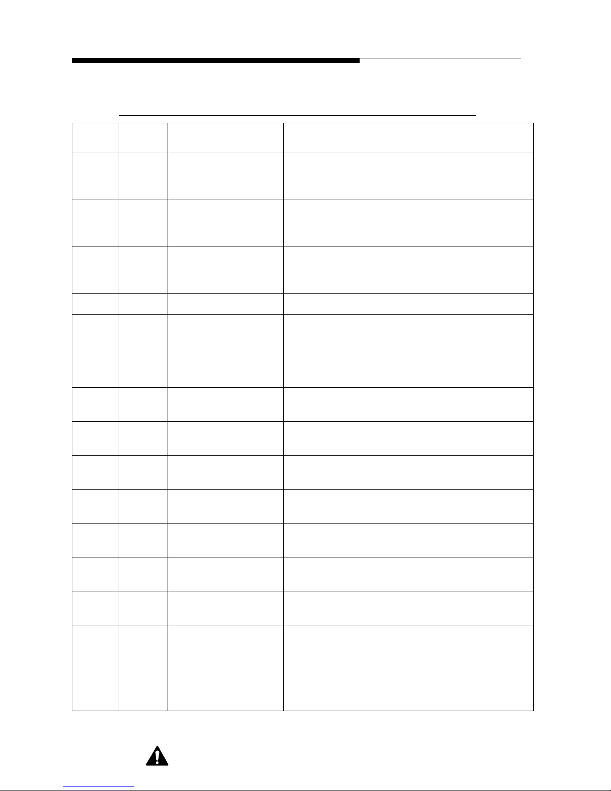
Z3-48HD+
Table 1-10 System Controller Remote Connections
Section I Operator Guide
Terminal
Remote
J1-1 J11-1 TX ON LOW
Terminal
Serial
Function Remarks
Momentary connection to ground sets the system
COMMAND
to LOW POWER ON mode. Maximum open
circuit voltage is approximately 15VDC
J1-2 J11-14 TX ON HIGH
COMMAND
Momentary connection to ground sets the system
to HIGH POWER ON mode. Maximum open
circuit voltage is approximately 15 VDC.
J1-3 J11-2 TX OFF COMMAND Momentary connection to ground sets the system
to OFF mode. Maximum open circuit voltage is
approximately 15 VDC.
J1-4 J11-15 SPARE COMMAND Not used.
J1-5 N/A MASTER FAIL-
SAFE
Connection to +15 VDC source at J1-25 through a
normally closed contact set, in customer
equipment, allows transmitter operation. If not
used, a jumper must be installed between this
terminal and J1-25.
J1-6 N/A MASTER
INTERLOCK
Not available for use. This input is used for the
combiner reject load in this configuration.
J1-7 J11-4 R/C STATUS Provides a connection to ground through 200
Ohms when the REMOTE mode has been selected.
J1-8 J11-17 FWD PWR SAMPLE Provides 0-4 VDC sample through 2k Ohms of the
RF forward output power.
J1-9 J11-5 RFL PWR SAMPLE Provides 0-4 VDC sample through 2k Ohms of the
RF reflected output power.
J1-10 J11-18 REJ PWR SAMPLE Provides 0-4 VDC sample through 2k Ohms of the
RF reject load power.
J1-11 J11-6 IPA A PWR
Not used.
SAMPLE
J1-12 J11-19 IPA B PWR
Not used.
SAMPLE
J1-13 J11-7 SWR FAULT
STATUS
Provides ground connection through 200 Ohms
when the reflected output RF power level has
exceeded the safe operating level , and the system
controller has terminated transmitter operation.
Can sink 25mA to ground and is suitable for use
with circuits up to 15 VDC.
12/5/07 888-2621-001 1-17
WARNING: Discon nect primar y power prior t o servicing .
Page 30
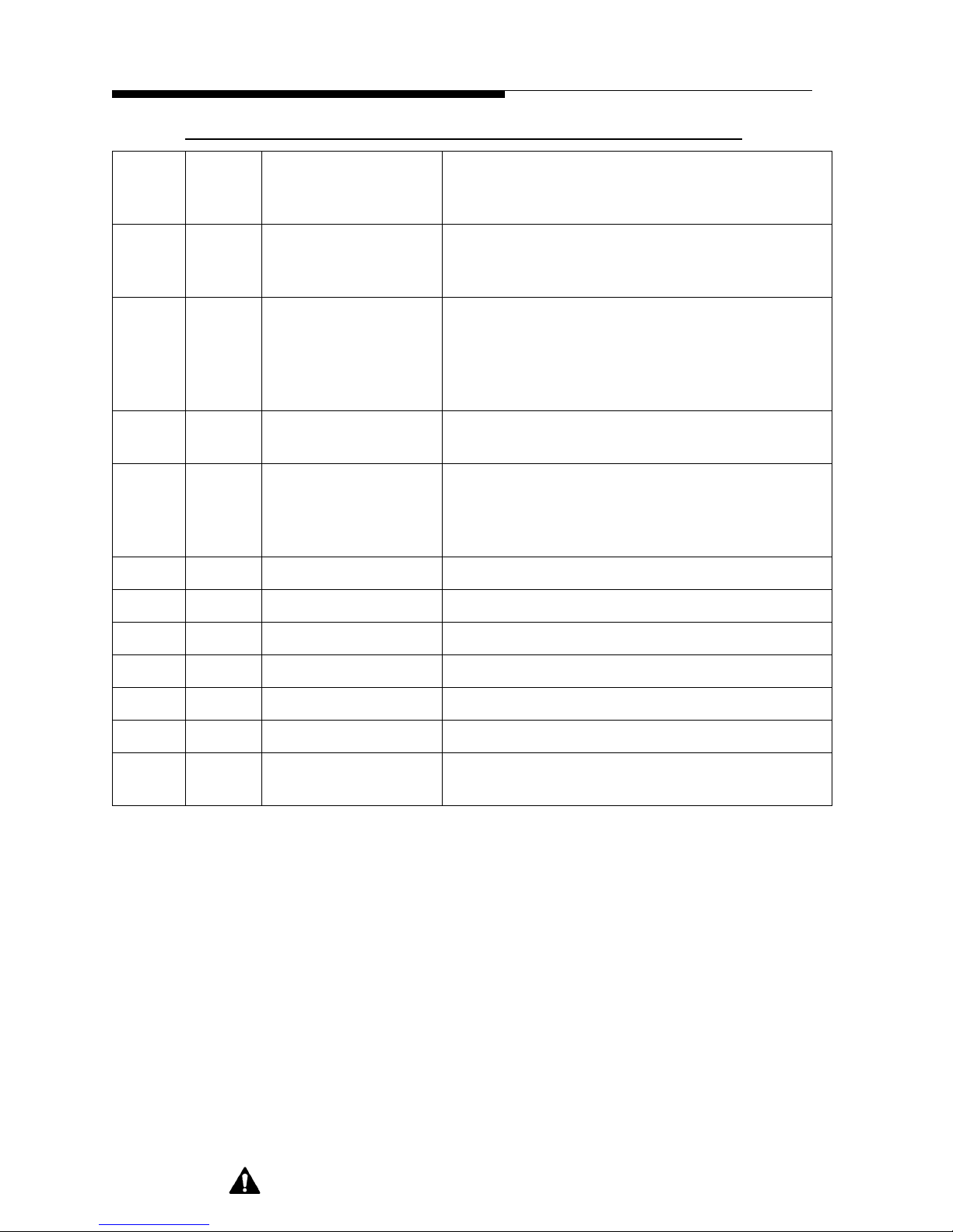
Section I Operator Guide
Z3-48HD+
Table 1-10 System Controller Remote Connections
J1-14 J11-20 LOW RF STATUS Provides ground connection through 200 Ohms
when the forward RF output power level drops
below a preset level.
J1-15 J11-8 REJ PWR
WARNING
J1-16 J11-21 REJ PWR FAULT Provides ground connection through 200 Ohms
J1-17 J11-9 TX ON STATUS Provides ground connection through 200 Ohms
J1-18 J 11-22 TX LOW POWER
STATUS
J1-19 J11-10 N/C
J1-20 J11-23 N/C
J1-21 J11-11 N/C
J1-22 J11-24 N/C
Provides ground connection through 200 Ohms
when the forward RF output power to the
combiner reject load exceeds a preset lev el.
when the forward RF output power to the
combiner reject load exce eds the safe operating
level and the system controller has terminated
transmitter operation.
when either transmitter is in the ON mode.
Provides ground connection through 200 Ohms
when either transmitter is in LOW POW ER ON
mode. Can sink 25mA to ground and is s uitable fo r
use with circuits up to 15 VDC.
J1-23 J11-12 GROUND Provides connection to circuit ground.
J1-24 J11-25 GROUND Provides connection to circuit ground.
J1-25 +15 VDC Provides connection to a current limited +15 VDC
used for external interlock and fail-safe signaling.
1-18 888-2621-001 12/5/07
WARNING: Disconnect prim ary power prior to servic ing.
Page 31

Section II
Parts List
2.1 Parts List
Replaceable Parts List Index
Table 2-1 XMTR, Z3-48HD+ HYB, FORMAT - - - - - - - - - - - 994 9712 005 2-2
Table 2-2 CABLE PKG, EXTENDER CABLES SYS CTRL - - - - 917 2332 878 (A) 2-2
Table 2-3 CABLE PKG, RF & CTLR, Z3-XX - - - - - - - - - - - 917 2332 993 (A) 2-2
Table 2-4 ASSY, DIR COUPLER- - - - - - - - - - - - - - - - - 927 8096 010 (E) 2-3
Table 2-5 ASSY, DIR COUPLER- - - - - - - - - - - - - - - - - 927 8096 012 (A) 2-3
Table 2-6 ASSY, DETECTOR - - - - - - - - - - - - - - - - - - 928 5652 003 (A) 2-3
Table 2-7 CONTROLLER, SYSTEM - - - - - - - - - - - - - - - 992 8850 005 (F) 2-3
Table 2-8 DISPLAY BD, DUAL TX CNTRL - - - - - - - - - - 992 8388 005 (E) 2-4
Table 2-9 PWA, SYSTEM CONTROLLER - - - - - - - - - - - 992 8853 001 (M) 2-5
Table 2-10 XMTR, ZD24/32HD+HYB, FORMAT - - - - - - - - - 994 9712 003 (A) 2-7
2
WARNING: Disconnect primary power prior to servicing.
888-2621-001 2-1
Page 32

Z3-48HD+
Section II Parts List
Table 2-1 XMTR, Z3-48HD+ HYB, FORMAT - 994 9712 005
Harris PN Description Qty UM Reference Designators
250 0129 000 CORD, 3C 16AWG TYPE SJ 0 FT
250 0626 000 CORD, AC, IEC PLUG TO IEC RECP 2 EA #SYS CNTRLS
358 3197 000 SLIDES 10" PAIR 0 PR
384 0357 000 DIODE, RECT 1N4004 1 EA
612 1291 000 PLUG, 3 WIRE FEMALE AC 0 EA
620 0498 000 ADAPTOR 3-1/8 5 EA
620 0544 000 CONN, ANCHOR INS 3-1/8; 50 OHM 1 EA
620 0581 000 COUPLING, SLEEVE, 3-1/8 3 EA
620 1563 000 SPLITTER, 2-WAY-0, BNC 1 EA SP2
620 2275 000 ELBOW, EQUAL, 3-1/8, 90 DEG 3 EA
700 1408 000 LOAD, 10KW 230VAC 50 OHM 1 EA
901 0207 021 PWA, D/A FILTER 0 EA
901 0207 271 PWA, CAN ADAPTER 1 EA
917 2332 280 SPACER SYS CTLR MOUNTING 0 EA
917 2332 878 CABLE PKG, EXTENDER CABLES SYS CTRL1 EAW4A,W5A
917 2332 993 CABLE PKG, RF & CTLR, Z3-XX 1 EA W4,W28,W30,W31,W32,W33,W35
917 2435 098 STRAP, SHIPPING 2 EA
922 1346 015 CABLE, CONTROL, W4A 1 EA
927 8096 010 ASSY, DIR COUPLER 1 EA
927 8096 012 ASSY, DIR COUPLER 1 EA
928 5652 003 ASSY, DETECTOR 3 EA
939 8013 089 TUBE, COAX 3.125 X 26.5LG 1 EA
939 8013 180 TUBE, COAX 3.125 X 49.25 LG 1 EA
939 8014 089 TUBE,COAX 1.315 X 24.97LG 1 EA
939 8014 180 TUBE, COAX 1.315 X 47.72 LG 1 EA
971 0027 006 FLEXSTAR BOOST AMP 0 EA
988 2621 001 DP, Z3-48HD+ 1 EA
992 8850 005 CONTROLLER, SYSTEM 1 EA
992 9854 012 KIT, PLAT Z MOUNTING, HDX-FM 0 EA
994 9712 003 XMTR, ZD24/32HD+HYB, FORMAT 0 EA
995 0034 016 ! XMTR, Z16HD+, FORMAT 0 EA
DIE98694-4-77DBCOMBINER, IBOC 4.77DB 38KW 1 EA
Table 2-2 CABLE PKG, EXTENDER CABLES SYS CTRL - 917 2332 878 (A)
Harris PN Description Qty UM Reference Designators
922 1346 015 CABLE, CONTROL, W4A 1 EA
922 1346 016 CABLE, CONTROL, W5A 1 EA
Table 2-3 CABLE PKG, RF & CTLR, Z3-XX - 917 2332 993 (A)
Harris PN Description Qty UM Reference Designators
922 1203 425 CABLE, COAX, W30 1 EA
922 1203 426 CABLE, COAX, W31 1 EA
922 1203 427 CABLE, COAX, W32 1 EA
922 1203 432 CABLE, CONTROL W28 1 EA
922 1203 908 CABLE, CONTROL, W4 1 EA
952 9238 087 CABLE, CONTROL, W35/W33 1 EA
2-2 888-2621-001
WARNING: Disconnect prim ary power prior to servic ing.
Page 33

Z3-48HD+
Section II Parts List
Table 2-4 ASSY, DIR COUPLER - 927 8096 010 (E)
Harris PN Description Qty UM Reference Designators
358 0498 000 CLAMP, HOSE DIA 2.563 MIN 3.50 MAX 2 EA
620 0581 000 COUPLING, SLEEVE, 3-1/8 1 EA
827 8096 010 ASSY INSTR, DIR COUPLER 0 DWG
839 7900 147 INNER COND. 3-1/8 1 EA
939 8118 901 OUTER CONDUCTOR 2 HOLES, 1 EA
992 9701 002 ASSY, DIRECTIONAL COUPLER,42DB 1 EA
992 9701 005 ASSY, DIRECTIONAL COUPLER,49DB 2 EA
Table 2-5 ASSY, DIR COUPLER - 927 8096 012 (A)
Harris PN Description Qty UM Reference Designators
358 0498 000 CLAMP, HOSE DIA 2.563 MIN 3.50 MAX 2 EA
620 0581 000 COUPLING, SLEEVE, 3-1/8 1 EA
827 8096 011 ASSY INSTR, DIR COUPLER 0 DWG
839 7900 147 INNER COND. 3-1/8 1 EA
939 8118 902 OUTER CONDUCTOR, 1 HOLE, 1 EA
992 9701 002 ASSY, DIRECTIONAL COUPLER,42DB 1 EA
Table 2-6 ASSY, DETECTOR - 928 5652 003 (A)
Harris PN Description Qty UM Reference Designators
516 0781 000 CAP 220PF 5% 100V C0G 1 EA C3
548 2400 382 RES 6.98K OHM 1/2W 1% 1 EA R5
817 2332 769 ASSY INSTR, DETECTOR ASSY 0 DWG
817 2332 770 SCHEM, DETECTOR ASSY 0 DWG
448 0875 000 BOX SHIELDED 1 EA
516 0375 000 *CAP 0.010UF 20% 50V Z5U 1 EA C1
508 0261 000 CAP .022UF 200V 10% 1 EA C2
384 0321 000 *DIODE, SCHOTTKY, 5082-2800 1 EA CR1
540 1600 208 RES 200 OHM 3W 5% 4 EA R1,R2,R3,R4
254 0003 000 WIRE, BUS CU 18AWG 0.100 FT
Table 2-7 CONTROLLER, SYSTEM - 992 8850 005 (F)
Harris PN Description Qty UM Reference Designators
250 0274 000 CORD, AC, 3C, NEMA/IEC PLUG 1 EA
358 3223 000 FEMALE SCREWLOCK .56"4-40 1 EA
398 0081 000 FUSE,SLO CART 2A 250V 1 EA
472 1693 000 XFMR, PWR, DP241-6-28 1 EA
484 0296 000 * FILTER RFI POWER LINE 1 EA
813 4999 023 STDOFF 6-32X5/16 1/4 HEX 14 EA
839 8118 218 SCHEM, OVERALL PTD SYS 0 DWG
917 2435 050 HANDLE, CTLR/DIGIT 2 EA
922 1085 071 CABLE, PT CONTROLLER 1 EA
922 1200 002 CABLE ASSY, RIBBON, 25C 1 EA
922 1203 113 WINDOW, SYSTEM CONTROLLER 1 EA
939 8118 180 COVER, SYSTEM CONTROLLER 1 EA
943 5293 071 FRAME, FRONT PANEL MTG. 1 EA
943 5293 072 REAR PNL, SYSTEM CONTROL 1 EA
943 5293 075 CHASSIS, SYSTEM CONTROL 1 EA
943 5293 646 FRONT PANEL, SYSTEM CONTROL, 1 EA
992 8388 005 DISPLAY BD, DUAL TX CNTRL 1 EA
992 8853 001 PWA, SYSTEM CONTROLLER 1 EA
888-2621-001 2-3
WARNING: Discon nect primar y power prior t o servicing .
Page 34

Z3-48HD+
Section II Parts List
Table 2-8 DISPLAY BD, DUAL TX CNTRL - 992 8388 005 (E)
Harris PN Description Qty UM Reference Designators
000 0000 010 B/M NOTE: 0 DWG
358 1928 000 JUMPER 1/4 LG 1/8H 7 EA JP1,JP4,JP10,JP11,JP12,JP13,JP14
358 3383 000 JUMPER, 0.1" LG, 0.125" H 5 EA JP015,JP016,JP17
380 0125 000 XSTR, NPN 2N4401 ES D 1 EA Q003
380 0189 000 *XSTR, NPN, MMBT3904 1 EA Q002
380 0190 000 *XSTR, PNP, MMBT3906 2 EA Q001,Q005
382 0401 000 *IC, CD4028B 1 EA U003
382 0523 000 *IC, CD4066 2 EA U009,U010
382 1207 000 IC CD4076B ESD 1 EA U002
382 1208 000 IC CD4070B ESD 4 EA U005,U006,U007,U008
382 1209 000 IC CD4532B ESD 1 EA U001
382 1210 000 IC CD4538B ESD 1 EA U004
382 1211 000 IC ICL7136 ESD 1 EA U011
384 0205 000 *DIODE, RECT 1N4148/914 30 EA
384 0826 000 LED LIGHT BAR, RED ESD 4 EA DS004,DS005,DS006,DS011
384 0827 000 LED LIGHT BAR, GREEN ESD 2 EA DS009,DS010
384 0849 000 LED LIGHT BAR, GREEN ESD 1 EA DS007
384 0850 000 LED LIGHT BAR, RED ESD 2 EA DS003,DS008
384 0858 000 LED LIGHT BAR, YELLOW ESD 1 EA DS013
386 0135 000 *ZENER 1N4733A 5.1V 5% 1W 1 EA CR032
404 0824 000 SOCKET, DIP14, LO PROFILE 6 EA
404 0825 000 SOCKET, DIP16, LO PROFILE 4 EA XU001,XU002,XU003,XU004
404 0828 000 SOCKET, SIP18, STRAIGHT 4 EA
406 0529 000 DISPLAY, LCD 3.5 DIGIT CUSTOM 1 EA DS012
500 1274 000 CAP 51PF 100V 5% 1 EA C003
506 0262 000 CAP, 0.047UF 100V 5% 1 EA C006
516 0484 000 CAP 0.100UF 10% 100V X7R CK06 20 EA
522 0581 000 CAP 10UF 35V 20% 2 EA C002,C026
540 1485 000 RES NETWORK 100K OHM 2% 2 EA R001,R016
548 2400 234 RES 221 OHM 1/2W 1% 1 EA R008
548 2400 242 RES 267 OHM 1/2W 1% 1 EA R034
548 2400 301 RES 1K OHM 1/2W 1% 1 EA R027
548 2400 312 RES 1.3K OHM 1/2W 1% 10 EA
548 2400 366 RES 4.75K OHM 1/2W 1% 1 EA R033
548 2400 401 RES 10K OHM 1/2W 1% 10 EA
548 2400 466 RES 47.5K OHM 1/2W 1% 2 EA R004,R011
548 2400 526 RES 182K OHM 1/2W 1% 1 EA R003
548 2400 601 RES 1MEG OHM 1/2W 1% 1 EA R002
CR001,CR002,CR003,CR004,CR005,CR0
06,CR007,CR008,CR009,CR010,CR011,
CR012,CR013,CR014,CR015,CR016,CR0
17,CR019,CR020,CR021,CR022,CR023,
CR024,CR025,CR026,CR027,CR031,CR0
33,CR034,CR035
XU005,XU006,XU007,XU008,XU009,X
U010
C001,C004,C005,C007,C008,C009,C010,
C011,C012,C013,C014,C015,C016,C017,
C018,C019,C020,C021,C022,C023
R017,R018,R019,R020,R021,R022,R023,
R024,R031,R032
R006,R007,R010,R012,R013,R014,R015,
R025,R026,R035
2-4 888-2621-001
WARNING: Disconnect prim ary power prior to servic ing.
Page 35

Z3-48HD+
Section II Parts List
548 2400 626 RES 1.82MEG OHM 1/2W 1% 1 EA R009
550 0953 000 TRIMPOT 20K OHM 1/2W 10% 1 EA R005
604 1111 000 SW PB GRAY MOM W/O LED 5 EA S001,S003,S005,S009,S010
604 1119 000 SW PB RED MO M W/O LED 1 EA S011
604 1261 000 SW PB GRAY ALT-ACTION W/O LED 1 EA S008
610 0933 000 TEST POINT, OVAL-LOOP THRU 12 EA
TP001,TP002,TP003,TP004,TP005,TP006
,TP007,TP008,TP009,TP010,TP011,TP01
2
610 1106 000 HDR, 8PIN, 1ROW, STRT,POL 1 EA J014
610 1441 034 HDR, 34C 2ROW VERTICAL 1 EA J001
839 8025 004 SCHEM, DISPLAY BD 0 DWG
843 5215 004 PWB, DISPLAY 1 EA
Table 2-9 PWA, SYSTEM CONTROLLER - 992 8853 001 (M)
Harris PN Description Qty UM Reference Designators
000 0000 010 B/M NOTE: 0 DWG
354 0309 000 TERM SOLDER 25 EA
358 1214 000 SCREWLOCK, M/F 4-40X3/16" 5 EA
380 0189 000 *XSTR, NPN, MMBT3904 15 EA
380 0190 000 *XSTR, PNP, MMBT3906 7 EA Q008,Q012,Q013,Q019,Q020,Q021,Q022
382 0184 000 IC, 340T-5/7805 +5V REG ESD 1 EA U019
382 0359 000 IC, 7815 ESD 1 EA U016
382 0360 000 IC, 7915 ESD 1 EA U017
382 0465 000 IC, 74C74 ESD 1 EA U012
382 0605 000 IC 7905C ESD 1 EA U018
382 0711 000 *PRECISION IC MULTIPLIER ESD 1 EA U009
382 0719 000 *IC, LM324A (DIP-14) 4 EA U005,U006,U007,U008
382 1016 000 *IC, 74C240 (DIP-20) 2 EA U004,U011
382 1017 000 *IC, 74C244 (DIP-20) 2 EA U003,U013
382 1070 000 IC, ILQ1 1 EA U001
382 1084 000 IC, LP339 (DIP-14) 1 EA U010
384 0205 000 *DIODE, RECT 1N4148/914 38 EA
384 0321 000 *DIODE, SCHOTTKY, 5082-2800 15 EA
384 0357 000 DIODE, RECT 1N4004 14 EA
384 0610 000 LED, GRN T1-3/4 VERT 4 EA DS001,DS002,DS003,DS004
384 0719 000 DIODE, TVS (UNIDIR), SA5.0A ESD 1 EA CR063
TP001,TP002,TP003,TP004,TP005,TP006
,TP007,TP008,TP009,TP010,TP011,TP01
2,TP013,TP014,TP015,TP016,TP017,TP0
18,TP019,TP020,TP021,TP022,TP023,TP
024,TP025
Q001,Q002,Q003,Q004,Q005,Q006,Q007
,Q009,Q010,Q011,Q014,Q015,Q016,Q017
,Q018
CR002,CR003,CR004,CR005,CR006,CR0
09,CR010,CR012,CR016,CR017,CR018,
CR019,CR020,CR021,CR034,CR035,CR0
39,CR040,CR041,CR042,CR043,CR044,
CR045,CR047,CR048,CR051,CR052,CR0
53,CR054,CR055,CR056,CR057,CR058,
CR059,CR060,CR069,CR071,CR073
CR022,CR023,CR024,CR025,CR026,CR0
27,CR028,CR029,CR030,CR031,CR032,
CR033,CR036,CR037,CR038
CR007,CR008,CR013,CR014,CR049,CR0
50,CR061,CR062,CR064,CR065,CR066,
CR067,CR072,CR075
WARNING: Discon nect primar y power prior t o servicing .
888-2621-001 2-5
Page 36

Z3-48HD+
Section II Parts List
384 0720 000 DIODE, TVS (UNIDIR), 1.5KE15A 3 EA CR068,CR074,CR077
384 0743 000 DIODE ARRAY DUAL 8 ESD 3 EA U002,U014,U015
384 0838 000 DIODE, TVS (UNIDIR), 1.5KE36A 2 EA CR070,CR078
384 0854 000 DIODE ARRAY, 8 ISOLATED ESD 2 EA CR001,CR046
386 0085 000 *ZENER 1N4740A 10V 5% 1W 1 EA CR015
404 0303 000 SOCKE T IC 10 PIN 1 EA XU009
404 0513 000 HEAT SINK PA1-1CB 4 EA #U016,#U017,#U018,#U019
404 0674 000 SOCKET, DIP, 14 PIN (DL) 9 EA
XU002,XU005,XU006,XU007,XU008,X
U010,XU012,XU014,XU015
404 0675 000 SOCKET, DIP, 16 PIN (DL) 3 EA CR001,CR046,XU001
404 0767 000 SOCKET, DIP, 20 PIN (DL) 4 EA XU003,XU004,XU011,XU013
494 0218 000 CHOKE, WIDE BAND 2.5 TURN 2 EA
506 0230 000 CAP .001UF 100VAC 5% 36 EA
516 0453 000 CAP 0.100UF 10% 100V X7R 23 EA
516 0511 000 CAP 0.47UF 100V 20% 1 EA C075
522 0524 000 CAP 10 UF 100V 20% NON-POLAR 1 EA C076
522 0548 000 CAP 10UF 50V 20% (5X11) 6 EA C026,C029,C049,C053,C070,C071
522 0586 000 CAP 3300UF 50V 20% 2 EA C050,C069
526 0109 000 CAP 22UF 25V 20% 2 EA C024,C027
526 0349 000 CAP 2.2UF 50V 20% 4 EA C052,C055,C057,C073
540 0618 000 *RES 2K OHM 2W 10% 2 EA R216,R217
540 1357 000 RES NETWORK 1000 OHM 2% 4 EA R001,R004,R005,R006
540 1366 000 RES NETWORK 100 OHM 2% 6 EA R002,R003,R007,R008,R009,R010
548 2051 000 RES ZERO OHM 5 EA R038,R048,R076,R099,R140
548 2400 201 RES 100 OHM 1/2W 1% 2 EA R020,R163
548 2400 209 RES 121 OHM 1/2W 1% 2 EA R207,R208
548 2400 268 RES 499 OHM 1/2W 1% 1 EA
548 2400 273 RES 562 OHM 1/2W 1% 2 EA R220,R221
548 2400 281 RES 681 OHM 1/2W 1% 4 EA R016,R017,R226,R227
548 2400 301 RES 1K OHM 1/2W 1% 13 EA
548 2400 318 RES 1.5K OHM 1/2W 1% 3 EA R058,R218,R219
548 2400 327 RES 1.87K OHM 1/2W 1% 5 EA R044,R064,R079,R096,R144
548 2400 330 RES 2K OHM 1/2W 1% 5 EA R154,R164,R166,R174,R176
548 2400 335 RES 2.26K OHM 1/2W 1% 5 EA R036,R054,R069,R106,R117
548 2400 336 RES 2.32K OHM 1/2W 1% 1 EA R130
548 2400 338 RES 2.43K OHM 1/2W 1% 1 EA R057
548 2400 358 RES 3.92K OHM 1/2W 1% 4 EA R071,R089,R104,R135
548 2400 366 RES 4.75K OHM 1/2W 1% 7 EA R019,R034,R056,R067,R108,R111,R187
548 2400 368 RES 4.99K OHM 1/2W 1% 12 EA
548 2400 385 RES 7.5K OHM 1/2W 1% 2 EA R160,R171
548 2400 393 RES 9.09K OHM 1/2W 1% 2 EA R128,R131
C001,C002,C003,C004,C005,C006,C007,
C008,C010,C012,C013,C014,C015,C017,
C018,C020,C021,C023,C030,C031,C032,
C033,C034,C035,C036,C037,C038,C039,
C040,C041,C043,C044,C045,C046,C047,
C048
C009,C011,C016,C019,C022,C025,C028,
C051,C054,C056,C058,C059,C060,C061,
C062,C063,C064,C065,C066,C067,C068,
C072,C074
R012,R015,R018,R022,R023,R025,R027,
R029,R121,R122,R129,R159,R170
R035,R049,R055,R066,R068,R075,R086,
R087,R107,R110,R114,R133
2-6 888-2621-001
WARNING: Disconnect prim ary power prior to servic ing.
Page 37

Z3-48HD+
Section II Parts List
548 2400 401 RES 10K OHM 1/2W 1% 45 EA
R013,R014,R030,R043,R046,R050,R053,
R059,R065,R074,R077,R098,R100,R101,
R109,R118,R138,R139,R141,R142,R153,
R155,R156,R157,R167,R168,R177,R179,
R182,R185,R188,R193,R195,R196,R198,
R200,R203,R204,R206,R209,R210,R211,
R213,R215,R222
548 2400 430 RES 20K OHM 1/2W 1% 1 EA R152
548 2400 439 RES 24.9K OHM 1/2W 1% 5 EA R051,R061,R073,R102,R137
548 2400 447 RES 30.1K OHM 1/2W 1% 5 EA R031,R041,R082,R093,R147
548 2400 466 RES 47.5K OHM 1/2W 1% 22 EA
548 2400 468 RES 49.9K OHM 1/2W 1% 5 EA R042,R062,R081,R094,R146
548 2400 493 RES 90.9K OHM 1/2W 1% 5 EA R032,R040,R083,R092,R148
548 2400 501 RES 100K OHM 1/2W 1% 27 EA
548 2400 526 RES 182K OHM 1/2W 1% 5 EA R033,R039,R084,R091,R149
548 2400 566 RES 475K OHM 1/2W 1% 2 EA R162,R172
548 2400 601 RES 1MEG OHM 1/2W 1% 1 EA R194
550 0858 000 TRIMPOT 5K OHM 1/2W 10% 6 EA R080,R088,R095,R145,R158,R197
550 0947 000 TRIMPOT 1K OHM 1/2W 10% 1 EA R132
550 0956 000 TRIMPOT 2K OHM 1/2W 10% 5 EA R037,R045,R078,R097,R143
550 0958 000 TRIMPOT 10K OHM 1/2W 10% 2 EA R161,R169
550 0981 000 TRIMPOT 50 OHM 1/2W 10% 4 EA R070,R090,R105,R134
560 0060 000 MOV, 40WVAC, 3J, 7MM DISC 1 EA RV001
574 0366 000 RELAY, DPDT 12VDC 2A 4 EA K001,K002,K003,K004
610 0828 000 *HEAD ER, 26C TWO ROW VERTICAL 1 EA J011
610 0900 000 HDR, 3C VERT 1ROW UNSHR 9 EA
610 1106 000 HDR, 8PIN, 1ROW, STRT,POL 1 EA J012
610 1441 034 HDR, 34C 2ROW VERTICAL 1 EA J013
612 1180 000 *D RECP 15C RT ANGLE 4 EA J002,J003,J004,J005
612 1181 000 *D RECP 25C RT ANGLE 1 EA J001
612 1184 000 SHUNT JUMPER 0.1" CENTERS 9 EA
612 1268 000 RECEPTACLE RT ANG BNC 5 EA J006,J007,J008,J009,J010
839 8118 181 SCHEM, PTD SYS CONTROLLER 0 DWG
843 5293 076 PWB, PTD SYS CONTROLLER 1 EA
R165,R173,R175,R178,R181,R183,R184,
R186,R189,R190,R191,R192,R199,R201,
R202,R205,R212,R214,R223,R224,R225,
R228
R011,R021,R024,R026,R028,R047,R052,
R060,R063,R072,R085,R103,R112,R113,
R115,R116,R119,R120,R123,R124,R125,
R126,R127,R136,R150,R151,R180
JP001,JP002,JP003,JP004,JP005,JP006,JP
007,JP008,JP009
#JP001,#JP002,#JP003,#JP004,#JP005,#J
P006,#JP007,#JP008,#JP009
Table 2-10 XMTR, ZD24/32HD+HYB, FORMAT - 994 9712 003 (A)
Harris PN Description Qty UM Reference Designators
2520003000A *WIRE, MIL, 20AWG 1000V WHITE 0.3 FT #J2,#J3
354 0384 000 CONTACT, PIN 4 EA J2,J3
358 2635 000 CABLE TIE, PUSH MOUNT SNAP IN 7 EA
358 3197 000 SLIDES 10" PAIR 1 PR
384 0357 000 DIODE, RECT 1N4004 2 EA
408 0212 000 BACKSHELL, D-SUB 15C NO-SHIELD 2 EA #J2,#J3
606 0866 000 BREAKER, CIRCUIT 10A 1 EA A1CB2
WARNING: Discon nect primar y power prior t o servicing .
888-2621-001 2-7
Page 38

Z3-48HD+
Section II Parts List
610 0538 000 PLUG, DSUB 15PIN CRIMP-POKE 2 EA J2,J3
614 0048 000 TERM BLK, 2ROW 4-TERM 20A 1 EA A1TB7
620 0498 000 ADAPTOR 3-1/8 6 EA
620 0544 000 CONN, ANCHOR INS 3-1/8; 50 OHM 2 EA
620 0581 000 COUPLING, SLEEVE, 3-1/8 11 EA
620 0675 000 COUPLER, PI/2 HYBRID 1 EA
620 2275 000 ELBOW, EQUAL, 3-1/8, 90 DEG 10 EA
646 0972 000 *LABEL 117V 0 EA #A1TB7
646 0973 000 *LABEL, 230V 0 EA #A1TB7
700 1414 000 LOAD, 8898-315, 115VAC 0 EA
700 1415 000 LOAD, 5KW 230VAC 3-1/8 0 EA
822 1346 014 XMTR LAYOUT, ZD24/32HD+, HYBRID, W/FLEXSTAR0 DWG
822 1346 073 XMTR LAYOUT, ZD-HYB 1PH 0 DWG
901 0207 271 PWA, CAN ADAPTER 2 EA
917 2332 280 SPACER SYS CTLR MOUNTING 8 EA
917 2332 741 CABLE PKG, RF & CTLR 1 EA W4,W5,W28,W30,W31,W32
917 2332 879 CABLE PKG, COAX, ZDHD+ 1 EA W147,W902,W903,W901A,W901B
917 2435 098 STRAP, SHIPPING 2 EA
922 1203 406 SHIELD 4POS TERM BLK, 1 EA #A1TB7
922 1260 239 CABLE, RIBBON W211B 0 EA
922 1260 240 CABLE, RIBBON W212B 0 EA
927 8096 010 ASSY, DIR COUPLER 1 EA
927 8096 012 ASSY, DIR COUPLER 1 EA
928 5652 003 ASSY, DETECTOR 3 EA
939 8013 022 TUBING COAX 1 EA
939 8013 120 TUBE, COAX 3.125 X 34.25 LG 1 EA
939 8013 254 TUBE, COAX 3.125 X 67.75 LG 1 EA
939 8014 022 TUBE, COAX 1.315 X 8.22LG 1 EA
939 8014 120 TUBE, COAX 1.315 X 32.72 LG 1 EA
939 8014 254 TUBE, COAX 1.315 X 66.22 LG 1 EA
971 0027 006 FLEXSTAR BOOST AMP 1 EA
988 2514 003 DWG PKG, ZD24/32HD+, HYBRID 1 EA
988 2515 001 DP, SYSTEM ZDHD 1 EA
992 8850 005 CONTROLLER, SYSTEM 1 EA
992 9854 012 KIT, PLAT Z MOUNTING, HDX-FM 1 EA
995 0034 012 ! XMTR, Z12HD+, FORMAT 0 EA
995 0034 016 ! XMTR, Z16HD+, FORMAT 0 EA
2-8 888-2621-001
WARNING: Disconnect prim ary power prior to servic ing.
 Loading...