

Page 1

Operator’s Manual
14221-1200-2010
Rev. E, April 2015
UNITY® XG-100M Mobile Radio
With CH-100 Control Head
Full-Spectrum Multiband Radio
Page 2

14221-1200-2010, Rev. E
REV.
DATE
REASON FOR CHANGE
-
Oct/11
Initial release.
A
Mar/12
Added information on using noise cancellation.
B
Jan/13
Updated to include R3A features.
C
May/14
Included manual channel entry, TA indication, and protected keys.
D
Oct/14
Added Voice Annunciation and Channel Preset buttons. Updated scan and Talkaround sections.
E
Apr/15
Updated for XGP R5A.
Harris products comply with the Restriction of the Use of Certain Hazardous Substances in Electrical and
Electronic Equipment (RoHS) Directive.
This manual is published by
without any warranty. Improvements and changes to this manual necessitat ed by typographical errors,
inaccuracies of current information, or improvements to programs and/or equipment, may be made by
ice.
Such changes will be incorporated into new editions of this manual. No part of this manual may be reproduced or transmitted in any form or by any means,
electronic or mechanical, including photocopying and recording, for any purpose, without the expre
Copyright © 2011-2015, Harris Corporation.
MANUAL REVISION HISTORY
Harris Corporation, Public Safety and Professional Communications (PSPC) Business continually evaluates its technical publications for
completeness, technical accuracy, and organization. You can assist in this process by submitting your comments and suggestions to the
following:
Harris Corporation fax your comments to: 1-434-455-6851
PSPC Business or
Technical Publications e-mail us at: PSPC_TechPubs@harris.com
221 Jefferson Ridge Parkway
Lynchburg, VA 24501
ACKNOWLEDGEMENT
This product was developed using GEOTRANS, a product of the National Geospatial Intelligence Agency and U.S. Army Engineering
Research and Development Center. Use of this software does not indicate endorsement or approval of the product by the Secretary o f
Defense or the National Geospatial Intelligence Agency.
This device made under license under one or more of the following US patents: 4,590,473; 4,636,791; 5,148,482; 5,185,796; 5,271,017;
5,377,229; 4,716,407; 4,972,460; 5,502,767; 5,146,697; 5,164,986; 5,185,795.
The Advanced Multi-Band Excitation implementation 2 (AMBE+2) voice coding Technology embodied in this product is protected by
intellectual property rights including patent rights, copyrights and trade secrets of Digital Voice Systems, Inc. This voice coding
Technology is licensed solely for use within this Communications Equipment. The user of this Technology is explicitly prohibited from
attempting to extract, remove, decompile, reverse engineer, or disassemble the Object Code, or in any other way convert the Object Code
into a human-readable form. U.S. Patent Nos. #5,870,405, #5,826,222, #5,754,974, #5,701,390, #5,715,365, #5,649,050, #5,630,011,
#5,581,656, #5,517,511, #5,491,772, #5,247,579, #5,226,084 and #5,195,166.
CREDITS
Harris, VIDA, EDACS, NetworkFirst, and OpenSky are registered trademarks and TECHNOLOGY TO CONNECT, INFORM AND
PROTECT is a trademark of Harris Corporation.
Bluetooth is a registered trademark of Bluetooth SIG, Inc.
Motorola is a registered trademark of Motorola, Inc.
Windows is a registered trademark of Microsoft Corporation.
AMBE is a registered trademark and IMBE, AMBE+, and AMBE+2 are trademarks of Digital Voice Systems, Inc.
All brand and product names are trademarks, registered trademarks, or service marks of their respective holders.
NOTICE!
The material contained herein is subject to U.S. export approval. No export or re-export is permitted without written approval from the U.S.
Government. Rated: EAR99; in accordance with U.S. Dept. of Commerce regulations 15CFR774, Export Administration Regulations.
Information and descriptions contained herein are the property of Harris Corporation. Such information and descriptions may not be copied
or reproduced by any means, or disseminated or distributed without the express prior written permission of Harris Corporation, PSPC
Business, 221 Jefferson Ridge Parkway, Lynchburg, VA 24501.
Repairs to this equipment should be made only by an authorized service technician or facility designated by the supplier. Any repairs,
alterations or substitutions of recommended parts made by the user to this equipment not approved by the manufacturer could void the
user's authority to operate the equipment in addition to the manufacturer's warranty.
This product conforms to the European Union WEEE Directive 2012/19/EU. Do not dispose of this product in a public
landfill. Take it to a recycling center at the end of its life.
Harris Corporation
2
Harris Corporation at any time and without not
ss written permission of Harris Corporation.
Page 3

14221-1200-2010, Rev. E
Section Page
6.17 GROUP CALLS................................................................................................................... 27
TABLE OF CONTENTS
1. SAFETY SYMBOL CONVENTIONS .......................................................................................... 6
2. RF ENERGY EXPOSURE INFORMATION .............................................................................. 7
2.1 RF ENERGY EXPOSURE AWARENESS, CONTROL INFORMATION, AND
OPERATION INSTRUCTIONS FOR FCC OCCUPATIONAL USE
REQUIREMENTS ................................................................................................................. 7
2.1.1 Federal Communications Commission Regulations ............................................ 7
2.2 COMPLIANCE WITH RF EXPOSURE STANDARDS ...................................................... 8
2.2.1 Mobile Antennas (Vehicle Installations) .............................................................. 8
2.2.2 Approved Accessories .......................................................................................... 9
2.2.3 Contact Information ........................................................................................... 10
2.3 REGULATORY APPROVALS .......................................................................................... 10
2.3.1 Part 15 ................................................................................................................ 10
2.3.2 Industry Canada .................................................................................................. 10
3. OPERATION SAFETY RECOMMENDATIONS ..................................................................... 11
3.1 TRANSMITTER HAZARDS .............................................................................................. 11
3.2 SAFE DRIVING RECOMMENDATIONS ......................................................................... 11
4. OPERATING RULES AND REGULATIONS ........................................................................... 12
5. INTRODUCTION ......................................................................................................................... 13
6. BASIC OPERATION .................................................................................................................... 14
6.1 PROGRAMMING ............................................................................................................... 14
6.2 XG-100M CONTROLS ....................................................................................................... 14
6.3 DISPLAY ............................................................................................................................. 15
6.4 STATUS MESSAGES ......................................................................................................... 16
6.5 ALERT TONES ................................................................................................................... 17
6.6 BEFORE FIRST USE .......................................................................................................... 17
6.7 POWER ON AND SET VOLUME ..................................................................................... 17
6.8 CHANNEL PRESETS ......................................................................................................... 18
6.9 NOISE CANCELLATION .................................................................................................. 18
6.9.1 Enable Noise Cancellation ................................................................................. 18
6.9.2 Using Noise Cancellation ................................................................................... 19
6.9.3 The Effect of Distance from the Micropho ne..................................................... 19
6.9.4 Voice Microphone and Control Head Microphone Locations ........................... 19
6.10 TURN ENCRYPTION ON OR OFF ................................................................................... 20
6.11 USER INTERFACE PRIVILEGE LEVEL ......................................................................... 21
6.12 SELECT CHANNEL ........................................................................................................... 21
6.12.1 Select from Channel List .................................................................................... 21
6.12.2 Manually Enter Channel Number ....................................................................... 22
6.13 SELECT A ZONE/SYSTEM USING MENUS ................................................................... 23
6.14 VOICE ANNUNCIATION .................................................................................................. 23
6.15 USE TALKAROUND TO BYPASS REPEATER (ANALOG AND P25
CONVENTIONAL) ............................................................................................................. 24
6.16 INDIVIDUAL CALLS ........................................................................................................ 26
6.16.1 Transmit an Individual Call ................................................................................ 26
6.16.2 Receiving an Individual Call .............................................................................. 27
3
Page 4

14221-1200-2010, Rev. E
6.18 CALLER ID ......................................................................................................................... 28
7.8.3 Vote Scan (Analog and P25 Conventional Only) ............................................... 59
6.19 CALL ALERT (PAGE) - P25 TRUNKED ONLY .............................................................. 29
6.19.1 Send Alert ........................................................................................................... 29
6.19.2 Receive Alert ...................................................................................................... 30
6.20 TELEPHONE INTERCONNECT ....................................................................................... 30
6.21 DTMF ................................................................................................................................... 31
6.22 SCAN OPERATION ........................................................................................................... 32
6.22.1 Start Scan ............................................................................................................ 32
6.22.2 Stop Scan ............................................................................................................ 33
6.22.3 Nuisance Delete .................................................................................................. 34
6.23 VIEW GPS INFORMATION .............................................................................................. 35
6.24 EMERGENCY OPERATION ............................................................................................. 36
6.24.1 Declaring an Emergency Call ............................................................................. 36
6.24.2 Receiving an Emergency Call ............................................................................ 37
6.24.3 Stealth Emergency .............................................................................................. 37
6.25 ENCRYPTION BAR ........................................................................................................... 37
6.26 MDC-1200 (CONVENTIONAL ONLY) ............................................................................ 37
6.27 LIGHTS AND SIRENS ....................................................................................................... 38
6.28 PUBLIC ADDRESS (PA) .................................................................................................... 38
6.29 SHORTCUT MENU ............................................................................................................ 39
6.30 VEHICULAR REPEATER OPERATION .......................................................................... 39
7. ADVANCED OPERATIONS ....................................................................................................... 40
7.1 ENCRYPTION .................................................................................................................... 40
7.1.1 Create Keys Using Harris Key Admin ............................................................... 40
7.1.2 Load encryption Keys ........................................................................................ 40
7.1.3 Zeroize All from Radio ...................................................................................... 42
7.1.4 Protected Keys .................................................................................................... 43
7.1.5 Global Encryption .............................................................................................. 43
7.1.6 Select Keyset ...................................................................................................... 44
7.1.7 OTAR Configuration .......................................................................................... 45
7.2 ACTIVATE/VIEW MISSION PLAN ................................................................................. 45
7.3 USER-DEFINED ZONES/SYSTEMS ................................................................................ 46
7.3.1 Command Tactical Zone .................................................................................... 46
7.3.2 Mixed System/Zone ........................................................................................... 47
7.4 MIXED ZONE SCAN ......................................................................................................... 48
7.4.1 Creating Custom Scan Lists ............................................................................... 48
7.4.2 View/Edit Custom Scan Lists ............................................................................. 48
7.4.3 Custom Scan List Selection ................................................................................ 50
CH INFORMATION MENU ............................................................................................... 51
7.5
7.6 EDIT CHANNEL (ANALOG AND P25 CONVENT I ONAL ONLY) ............................... 51
7.7 SETTINGS MENU .............................................................................................................. 52
7.7.1 Audio Settings .................................................................................................... 53
7.7.2 Display Settings .................................................................................................. 54
7.7.3 GPS Settings ....................................................................................................... 54
7.7.4 Bluetooth ............................................................................................................ 55
7.7.5 Clock Settings .................................................................................................... 57
7.8 SET UP SCAN ..................................................................................................................... 58
7.8.1 Home, Priority 1, and Priority 2 Channels ......................................................... 58
7.8.2 Trunked/Conventional Scanning ........................................................................ 59
4
Page 5

14221-1200-2010, Rev. E
7.8.4 Set or Remove Priority 1 and Priority 2 Channels ............................................. 60
FIGURES
Page
Figure 6-1: Conventional Display ........................................................................................................... 15
TABLES
Page
Table 2-1 Recommended Minimum Safe Lateral Distance from a Transmitting Antenna Connected
7.8.5 Wide Area System Scan (P25 Trunked Only) .................................................... 60
7.9 MESSAGE MENU .............................................................................................................. 61
7.9.1 Radio Status........................................................................................................ 61
7.9.2 Radio Message ................................................................................................... 62
7.9.3 Radio TextLink (P25 Trunked Only) ................................................................. 63
7.9.4 Faults/Alerts ....................................................................................................... 65
7.10 UTILITIES MENU .............................................................................................................. 66
7.11 OTAP ................................................................................................................................... 67
7.12 PPP/SLIP .............................................................................................................................. 67
8. REFERENCE ................................................................................................................................. 68
8.1 MARINE FREQUENCIES .................................................................................................. 68
8.2 ACCESSORIES ................................................................................................................... 74
9. GLOSSARY ................................................................................................................................... 75
10. BASIC TROUBLESHOOTING ................................................................................................... 78
10.1 ERROR MESSAGES ........................................................................................................... 78
10.2 OTAR ERRORS/INFORMATION ..................................................................................... 79
11. CUSTOMER SERVICE ............................................................................................................... 80
11.1 CUSTOMER CARE ............................................................................................................ 80
11.2 TECHNICAL ASSISTANCE .............................................................................................. 80
12. WARRANTY ................................................................................................................................. 81
APPENDIX A - PPP/SLIP CONNECTION ....................................................................................... 82
Figure 6-2: P25 Trunked Display ............................................................................................................ 15
Figure 6-3: No Channel Presets ............................................................................................................... 18
Figure 6-4: Four Channel Presets ............................................................................................................ 18
Figure 6-5: Noise Microphone ................................................................................................................ 20
Figure 6-6: Voice Microphone ................................................................................................................ 20
Figure 6-7: User Interface Privilege ........................................................................................................ 21
to a Unity XG-100M Mobile Radio ................................................................................................... 8
Table 6-1: XG-100M Controls and Connectors ...................................................................................... 14
Table 6-2: Icons ....................................................................................................................................... 15
Table 6-3: Status Messages ..................................................................................................................... 16
Table 6-4: Alert Tones ............................................................................................................................. 17
Table 6-5: Encryption Bar Indications .................................................................................................... 37
Table 8-1: Marine Frequencies ................................................................................................................ 68
Table 8-2: Options and Accessories for the Unity XG-100M Mobile Radios ........................................ 74
Table 8-3: Options and Accessories for the CH-100 Control Head ........................................................ 74
5
Page 6
14221-1200-2010, Rev. E
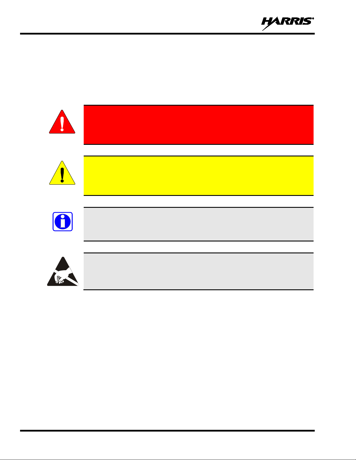
WARNING
The WARNING symbol calls attention to a procedure, practice, or the like,
which, if not correctly performed or adhered to, could result in personal injury.
CAUTION
which, if not performed correctly or adhered to, could result in a risk of danger,
NOTE
1. SAFETY SYMBOL CONVENTIONS
The following conventions are used to alert the user to gen eral safety precautions that must be observed
during all phases of operation, service, and repair of this product. Failure to comply with these
precautions or with specific warnings elsewhere violates safety standards of design, manufacture, and
intended use of the product. Harris assumes no liability for the customer's failure to comply with these
standards.
Do not proceed beyond a WARNING symbol until the conditions identified are
fully understood or met.
The CAUTION symbol calls attention to an operating procedure, practice, or the like,
damage to the equipment, or severely degrade the equipment performance.
The NOTE symbol calls attention to supplemental information, which may improve
system performance or clarify a process or procedure.
The ESD symbol calls attention to procedures, practices, or the like, which could
expose equipment to the effects of Electro-Static Discharge. Proper precautions must
be taken to prevent ESD when handling circuit modules.
6
Page 7
14221-1200-2010, Rev. E
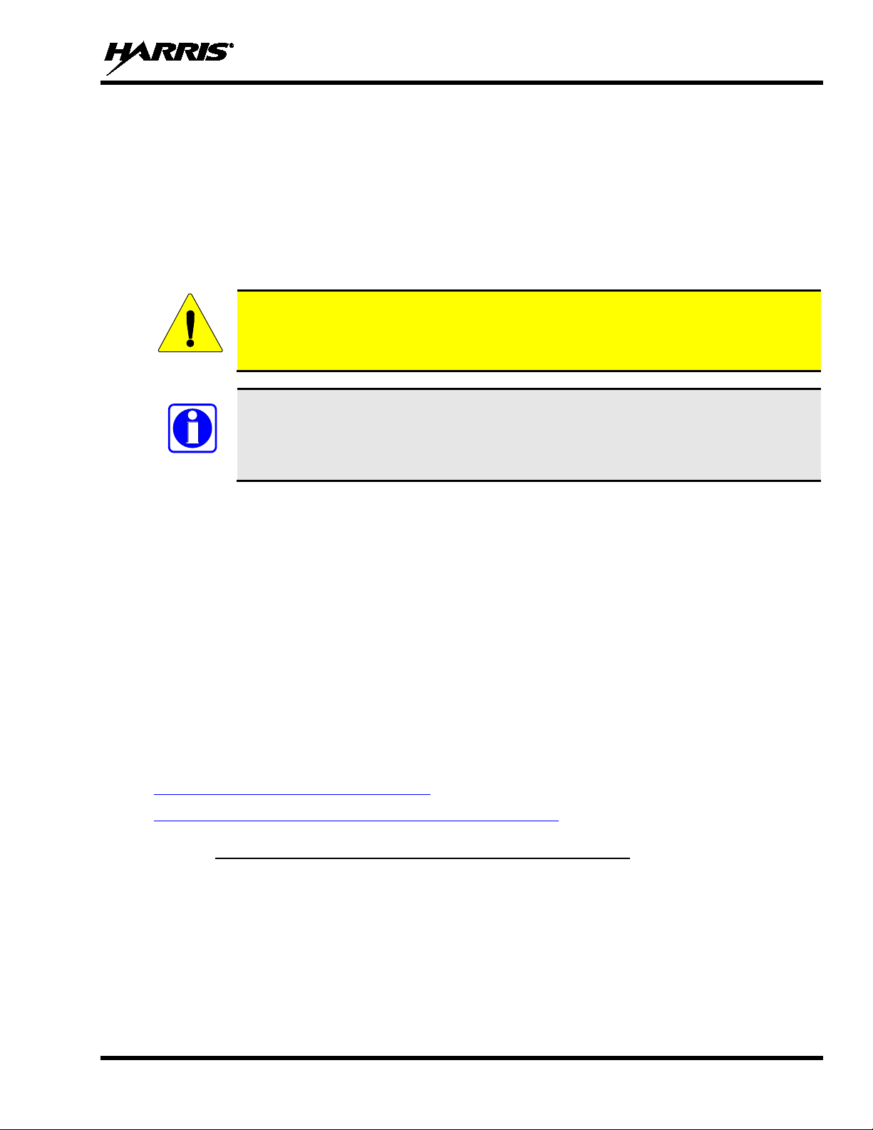
limits. This radio device is NOT authorized for general population, consumer, or any
CAUTION
NOTE
2. RF ENERGY EXPOSURE INFORMATION
2.1 RF ENERGY EXPOSURE AWARENESS, CONTROL INFORMATION, AND OPERATION INSTRUCTIONS FOR FCC OCCUPATIONAL USE REQUIREMENTS
Before using your mobile two-way radio, read this important RF energy awareness and control
information and operational instructions to ensure compliance with the FCC’s RF exposure
guidelines.
Changes or modifications not expressly approved by Harris could void the user's authority
to operate the equipment.
This radio is intended for use in occupational/controlled conditions, where users have full
knowledge of their exposure and can exercise control over their exposure to meet FCC
other use.
This two-way radio uses electromagnetic energy in the radio frequency (RF) spectrum to provide
communications between two or more users ov er a distan ce. It u ses RF en ergy or radio waves to sen d and
receive calls. RF energy is one form of electro magnetic energy. Other forms include, b ut are not limited
to, electric power, sunlight, and x-rays. RF energy, however, should not be confused with these other
forms of electromagnetic energy, which , when used improperly, can cause biol ogical damage. Very high
levels of x-rays, for example, can damage tissues and genetic material.
Experts in science, engineering, medicine, health, and industry work with organizations to develop
standards for exposure to RF energy. These standards provide recommended levels of RF exposure for
both workers and the general public. These reco mmended RF exp osure levels includ e substantial margin s
of protection. All two-way radios marketed in North America are designed, manufactured, and tested to
ensure they meet government estab lished RF exposur e levels. In addition , manufactu rers also recommend
specific operating instructions to users of two-way radios. These instructions are important because they
inform users about RF energy exposure and provide simple procedures on how to control it. Please refer
to the following websites for more information on what RF energy exposure is and how to control your
exposure to assure compliance with established RF exposure limits.
http://www.fcc.gov/oet/rfsafety/rf-faqs.html
http://www.osha.gov./SLTC/radiofrequencyradiation/index.html
2.1.1 Federal Comm unications Commission Regulations
Your Harris Unity mobile two-way radio is designed and tested to comply with the FCC RF energy
exposure limits for mobile two-way radios before it can be marketed in the United States. When two-way
radios are used as a consequence of employment, the FCC requires users to b e fully aware of and able to
control their exposure to meet occupation al requirements. Exposure awareness can be facilitated by the
use of a label directing users to specific user awareness information. Your Harris Unity two-way radio has
an RF exposure product label. Also, your Unity Mobile Installation and Operator’s Manuals include
information and operating instructions required to control your RF exposure and to satisfy compliance
requirements.
7
Page 8
14221-1200-2010, Rev. E
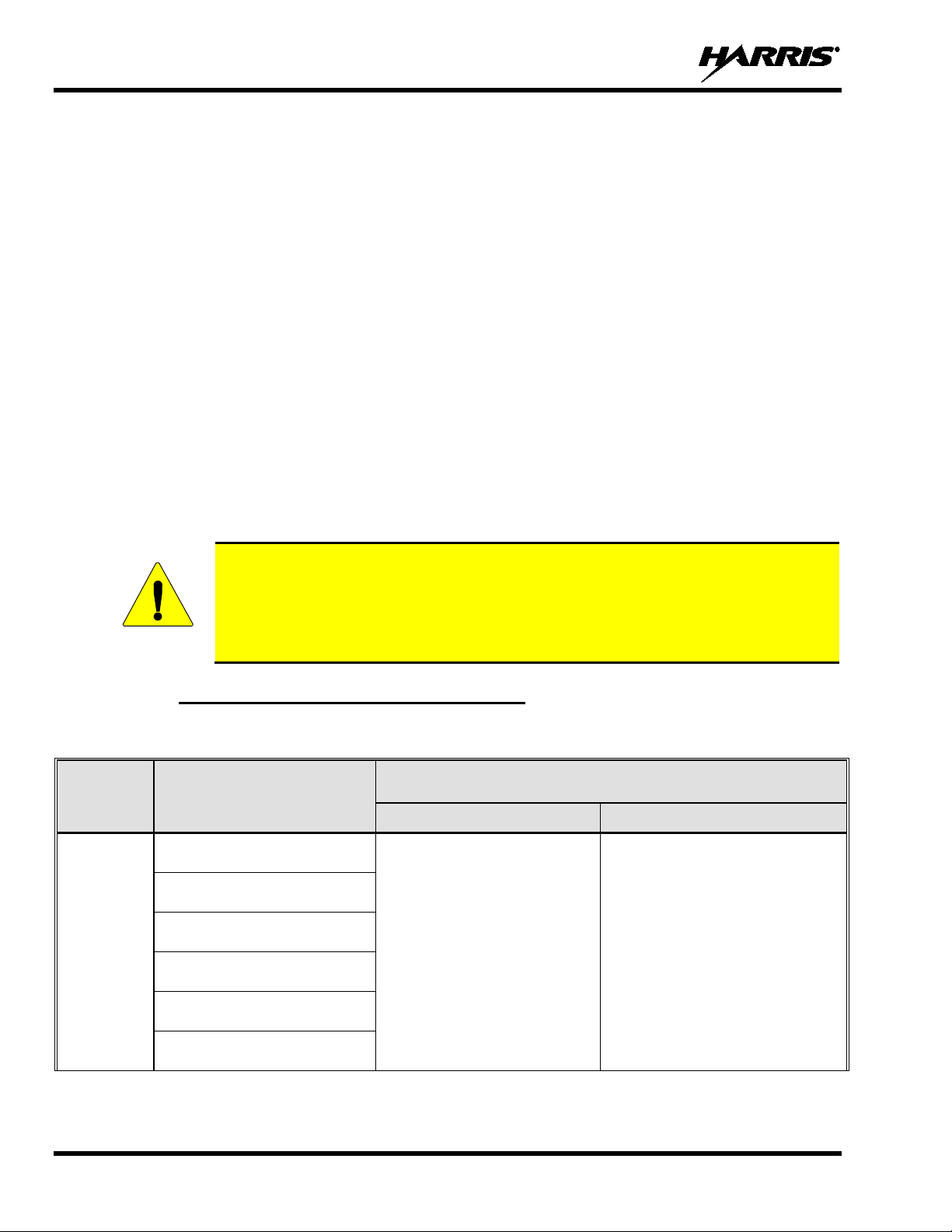
Table 2-1 li sts the reco mmended minimum lateral distance for a contro lled environment
antennas (i.e., monopoles over a ground plane, or dipoles) at rated radio power for
m the transmitting
antenna.
CAUTION
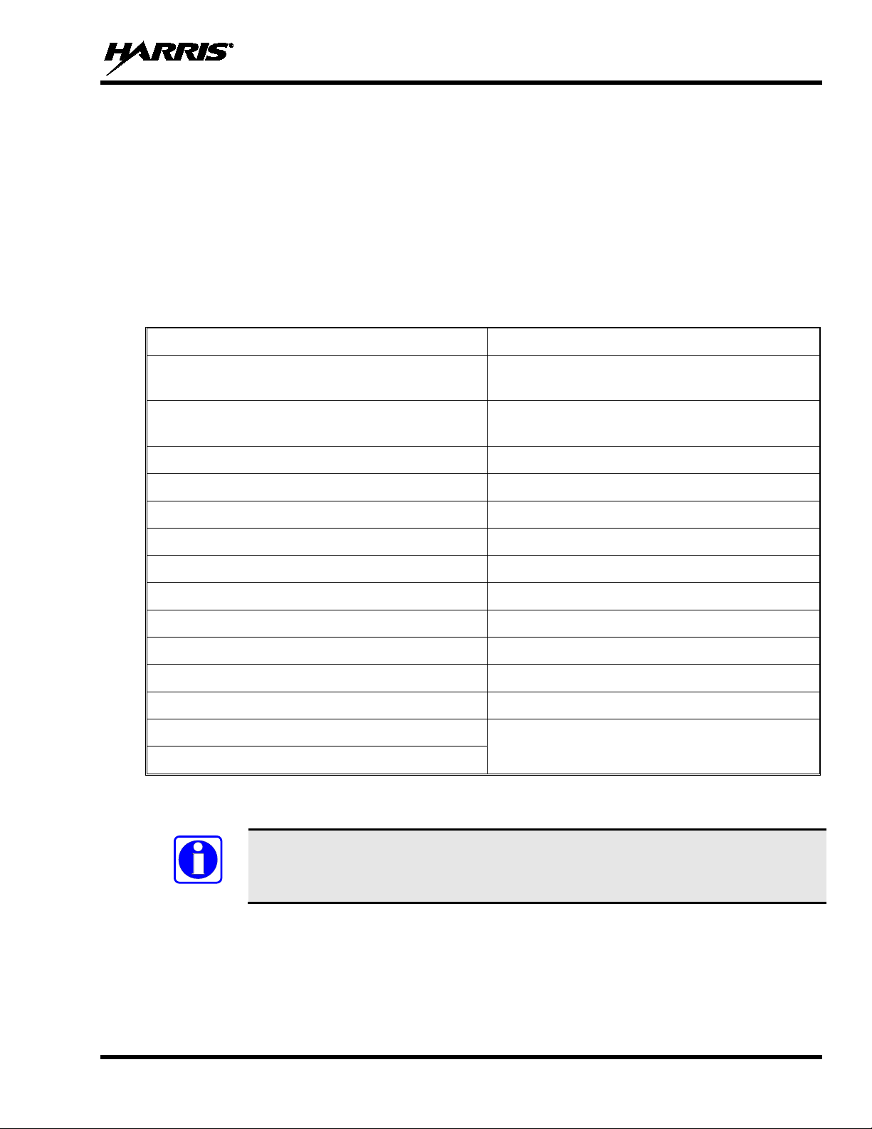
2.2 COMPLIANCE WITH RF EXPOSURE STANDARDS
Your Harris Unity mobile two-way radio is desi gned and tested to co mply with a number of national and
international standards and guidelines (listed below) regarding human exposure to RF electromagnetic
energy. This radio complies with the IEEE and ICNIRP exposure limits for occupational/controlled RF
exposure environment at duty factors of up to 50% talk-50% listen and is authorized by the FCC for
occupational use. In terms of measuring RF energy for compliance with the FCC exposure guidelines,
your radio antenna radiates measurable RF energy only while it is transmitting (talking), not when it is
receiving (listening) or in standby mode.
Your Harris Unity mobile two-way radio complies with th e following RF energy exposur e standards and
guidelines:
• United States Federal Communications Commission (FCC), Code of Federal Regulations; 47 CFR §§
2 sub-part J.
• American National Standards Institute (ANSI)/Institute of Electrical and Electronic Engineers (IEEE)
C95.1-2005.
• Institute of Electrical and Electronic Engineers (IEEE) C95.1-2005.
• IC standard RSS-102, Issue 2, 2005: “Spectrum Management and Telecommunications Radio
Standards Specification. Radiofrequency Exposure Compliance of Radiocommunication Apparatus
(All Frequency Bands).
and for unaware bystanders in an uncontrolled environment, from transmitting types of
mobile radios installed in a vehicle. Trans mit only when u naware by standers are at leas t
the uncontrolled recommended minimum lateral distance away fro
2.2.1 Mobile Antennas (Vehicle Installations)
Table 2-1 Recommended Minimum Safe Lateral Distance from a
Transmitting Antenna Connected to a Unity XG-100M Mobile Radio
RECOMMENDED MINIMUM LATERAL HUMAN BODY DISTANCE
CONTROLLED ENVIRONMENT UNCONTROLLED ENVIRONMENT
(72 centimeters)
RF BAND
VHF
ANTENNA
PART NUMBERS
AN-125001-002 (mount) with
12099-0310-01 (element)
AN-125001-004 (mount) with
12099-0310-01 (element)
AN-125001-006 (mount) with
12099-0310-01 (element)
AN-125001-008 (mount) with
12099-0310-01 (element)
AN-125001-002 (mount) with
12099-0330-01 (element)
AN-125001-004 (mount) with
12099-0330-01 (element)
FROM TRANSMITTING ANTENNA
28.3 inches
63.0 inches
(160 centimeters)
8
Page 9

14221-1200-2010, Rev. E
RF BAND
UHF
700/800 MHz
ANTENNA
PART NUMBERS
AN-125001-002 (mount) with
12099-0310-01 (element)
AN-125001-004 (mount) with
12099-0310-01 (element)
AN-125001-006 (mount) with
12099-0310-01 (element)
AN-125001-008 (mount) with
12099-0310-01 (element)
AN-125001-002 (mount) with
12099-0330-01 (element)
AN-125001-004 (mount) with
12099-0330-01 (element)
AN-125001-002 (mount) with
12099-0310-01 (element)
AN-125001-004 (mount) with
12099-0310-01 (element)
AN-125001-006 (mount) with
12099-0310-01 (element)
AN-125001-008 (mount) with
12099-0310-01 (element)
AN-125001-002 (mount) with
12099-0330-01 (element)
AN-125001-004 (mount) with
12099-0330-01 (element)
RECOMMENDED MINIMUM LATERAL HUMAN BODY DISTANCE
FROM TRANSMITTING ANTENNA
CONTROLLED ENVIRONMENT UNCONTROLLED ENVIRONMENT
24.4 inches
(62 centimeters)
33.9 inches
86 cm
7.9 inches
(20 centimeters)
7.9 inches
(20 centimeters)
54.3 inches
(138 centimeters)
75.6 inches
192 cm
19.7 inches
(50 centimeters)
24 inches
(61 centimeters)
* Install the radio’s antenna in the center of the vehicle’s roof. These mobile antenna installation guidelines
are limited to metal body motor vehicles or vehicles with appropriate ground planes. The antenna
installation should additionally be in accordance with the following:
• The requirements of the antenna manufacturer/supplier included with the antenna.
• Instructions in the Unity Mobile Radio Installation Manual, including minimum antenna cable
lengths.
• The installation manual providing specific information of how to install the antennas to facilitate
recommended operating distances to all potentially exposed persons.
Use only the Harris approved/supplied antenna(s) or approved replacement antenna. Unauthorized
antennas, modifications, or attachments could damage the radio and may violate FCC regulations.
2.2.2 Approved Accessor ies
This radio has been tested and meets the FCC RF guidelines when used with the Harris accessories
supplied or designated for use with this product. Use of other accesso ries may n ot ensu re co mp lian ce with
the FCC’s RF exposure guidelines, and may violate FCC regulations.
For a list of approved accessories refer to Section 8.2, the Products and Services Catalog, or contact
Harris at 1-800-368-3277.
9
Page 10

14221-1200-2010, Rev. E
2.2.3 Contact I nformation
For additional information on exposure requirements or other information, contact Harris at 1-800-5287711 or at www.pspc.harris.com.
2.3 REGULATORY APPROVALS
2.3.1 Part 15
This device complies with Part 15 of the FCC Rules. Operation is subject to the following two conditions:
1. This device may not cause harmful interference, and
2. This device must accept any interference received, including interference that may cause undesired
operation.
2.3.2 Industry Canada
This device complies with Industry Canada license-exempt RSS standard(s). Operation is sub ject to the
following two conditions: (1) this dev ice may not cause interfer ence, and (2) this dev ice must accept any
interference, including interference that may cause undesired operation of the device.
Le présent appareil est conforme aux C NR d'Industri e Canada app licables aux a ppareils radio ex empts de
licence. L'exploitation est autorisée aux deux conditions suivantes : (1) l'appareil ne doit pas produire de
brouillage, et (2) l'utilisateur de l'appareil doit accepter tout brouillage radioélectrique subi, même si le
brouillage est susceptible d'en compromettre le fonctionnement.
10
Page 11

14221-1200-2010, Rev. E
WARNING
3. OPERATION SAFETY RECOMMENDATIONS
3.1 TRANSMITTER HAZARDS
The operator of any mobile radio should be aware of certain h azards common to
the operation of vehicular radio transmitters. A list of several possible hazards is
given:
• Explosive Atmospheres – Just as it is dangerous to fuel a vehi cle with the motor running, similar
hazards exist when operating a mobile radio. Be sure to turn the radio off while fueling a vehicle. Do
not carry containers of fuel in the trunk of a vehicle if the radio is mounted in the trunk.
Areas with potentially explosive atmosphere are often, but not always, clearly marked. Turn OFF
your radio when in any area with a potentially explosive atmosphere. It is rare, but not impossible that
the radio or its accessories could generate sparks.
• Interference to Vehicular Electro nics Systems – Electronic fuel injection sy stems, electronic anti-
skid braking systems, electronic cruise con trol systems, etc., are typical electronic systems that can
malfunction due to the lack of protection from radio frequency energy present when transmitting. If
the vehicle contains such equipment, consult the dealer and enlist their aid in determining the
expected performance of electronic circuits when the radio is transmitting.
• Electric Blasting Caps – To prevent accidental detonatio n of electric blasting caps, DO NOT use
two-way radios within 1000 feet (305 meters) of blasting operations. Always obey the “Turn off
Two-Way Radios” signs posted where electric blasting cap s are being used. (OSHA St andard: 192 6-
900)
• Liquefied Petroleum (LP) Gas Powered Vehicles – Mobile radio installations in vehicles powered
by liquefied petroleum gas with the LP gas container in the trunk or other sealed-off space within the
interior of the vehicle must conform to the National Fire Protection Association standard NFPA 58
requiring:
The LP gas container and its fittings.
Outside filling connections shall be used for the LP gas container.
The LP gas container shall be vented to the outside of the vehicle.
3.2 SAFE DRIVING RECOMMENDATIONS
(Recommended by AAA)
• Read the literature on the safe operation of the radio.
• Keep both hands on the steering wheel and the microphone in its hanger whenever the vehicle is in
motion.
• Place calls only when the vehicle is stopped.
• When talking from a moving vehicle is unavoidable, drive in the slower lane. Keep conversations
brief.
• If a conversation requires taking notes or complex thought, stop the vehicle in a safe place and
continue the call.
• Whenever using a mobile radio, exercise caution.
11
Page 12

14221-1200-2010, Rev. E
NOTE
4. OPERA TING RULES AND REGULATIONS
Two-way FM radio systems must be operated in accordance with the rules a nd regulations of the local,
regional, or national government.
In the United States, the Unity mobile r adi o must b e o per ated i n acco rdan ce wi th the r ules an d r egu latio ns
of the Federal Communications Commission (FCC). As an operator of two-way radio equipment, you
must be thoroughly familiar with the rules that apply to your particular type of radio operation. Following
these rules helps eliminate confusion , assures the most efficient use of the existing radio channels, and
results in a smoothly functioning radio network.
When using your two-way radio, remember these rules:
• It is a violation of FCC rules to interru pt any distress or emergency messag e. As your radio operates
in much the same way as a telephone “party line,” always listen to make sure that the channel is clear
before transmitting. Emergency calls h ave priority over all other messages. If someone is sending an
emergency message – such as reporting a fire or asking for help in an accident – KEEP OFF THE
AIR!
• The use of profane or obscene language i s prohibited by Federal law.
• It is against the law to send false call letters or false distress or emergency messages. The FCC
requires that you keep conversations brief and confine them to business. To save time, use coded
messages whenever possible.
• Using your radio to send perso nal messages (except in an emergency) is a violation of F CC rules.
You may send only those messages that are essential for the operation of your business.
• It is against Federal law to repeat or otherwise make kno wn anything you overhear on your radio.
Conversations between others sharing your channel must be regarded as confidential.
• The FCC requires that you identi fy yourself at certain specific times by means of your call letters.
Refer to the rules that apply to your particular type of operation for the proper procedure.
• No changes or adjustments shall be made to the equipment except by an authorized or certified
electronics technician.
Under U.S. law, operation of an unlicensed radio transmitter within the jurisdiction of
the United States may be punishable by a fine of up to $10,000, imprisonment for up to
two (2) years, or both.
The following conditions tend to reduce the effective range of two-way radios and should be avoided
whenever possible:
• Operating the radio in areas of low terrain, or while under power lines or bridges.
• Obstructions such as mountains and buildings.
• In areas where transmission or reception is poor, some improvement can be obtained by moving a few
yards in another direction or moving to a higher elevation.
12
Page 13
14221-1200-2010, Rev. E
Digital Encryption Standard Output Feedback
Digital Encryption Standard Cipher Feedback
NOTE
5. INTRODUCTION
Your XG-100M provides full-spectrum multiband coverage:
• 30 to 50 MHz, VHF Low (Receive only)
• 136 to 174 MHz, VHF High (5 – 50 W)
• 380 to 520 MHz, UHF-Low, UHF-High (5 – 50 W)
• 762 to 805 MHz, 700 MHz (2 – 30 W)
• 805 to 870 MHz, 800 MHz (2 – 35 W)
The XG-100M includes the following capabilities:
Project 25 (P25) Conventional P25 Trunking
Analog FM Advanced Encryption Standard, 256-bit (AES-
256)
(DES-OFB) Encryption
Global Positioning System (GPS) Bluetooth®
P25 Trunking Over The Air Rekey (OTAR) Preemptive Priority Scanning
Global Common Key References (CKR) Vote Scan
PA Mode Lights and Sirens
Telephone Interconnect Calls (P25 Trunked Only) Status/Message (P25 Trunked and Conventional)
MDC-1200 Encode Programmable Minimum Volume
P25 Trunked Conventional Scan Mixed System Zones
Channel Guard Command Tactical Zones
Call Alert SLIP/PPP (P25 Trunked Only)
DTMF Bluetooth Emergency
Feature Management
Custom Scan
For optional accessories, refer to Section 8.2. Additional accessories may have been added since
publication of this manual; contact Harris for more information.
(DES-CFB) Encryption
Voice Annunciation
Refer to the Software Release Notes to determine the minimum software versions
required for features.
13
Page 14
14221-1200-2010, Rev. E
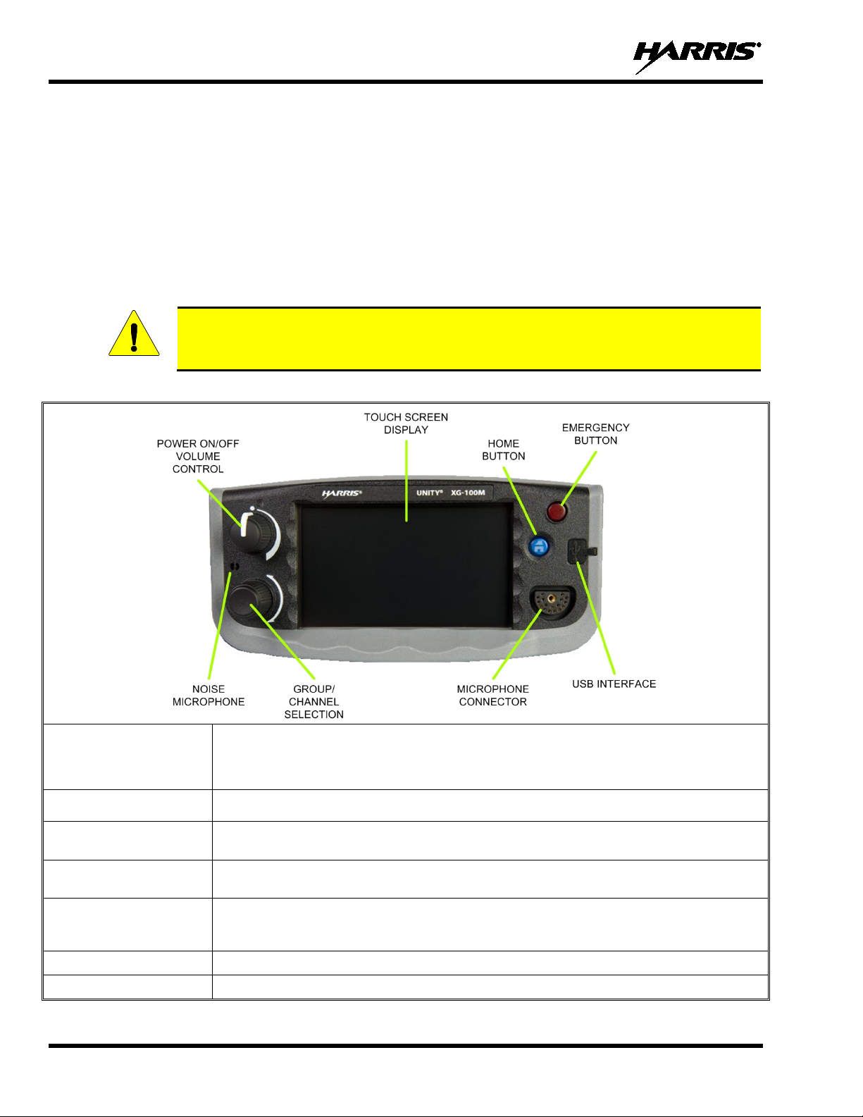
GROUP/CHANNEL
SELECTION
MICROPHONE
CONNECTOR
Toggles through three available main screens or allows you to quickly navi gate back to the main
hold for approximately one second).
EMERGENCY BUTTON
Declares an emergency.
USB Interface
Connection for Programming cable.
CAUTION
6. BASIC OPERATION
6.1 PROGRAMMING
Radio Personality Manager (RPM) is used to program the XG-100M. With RPM, you can fully program
the XG-100M using a USB cable (type A male to mini-type B).
6.2 XG-100M CONTROLS
The XG-100M features a full color touch screen display for easy access to all radio features and
functions. To select an item, simply touch the desired area of the screen with your finger.
Never touch the screen with any metal or shar p objects, as this can damage the screen!
Table 6-1: XG-100M Controls and Connectors
POWER ON/OFF
VOLUME CONTROL
NOISE MICROPHONE Used in conjunction with a handheld microphone and Harris’ built-in noise suppression.
HOME BUTTON
Turn knob clockwise to power on the radio and increase volume.
Turn counter-clockwise to decrease volume and power off the radio. Minimum volume levels
may be programmed into the radio to prev ent missed calls due to a low volume setting.
Selects the available groups or channels.
Connection for hand-held, hands-free, speaker-mic, or headset.
screen from a submenu. Can also be configured in RPM to go to a home channel (press and
14
Page 15
14221-1200-2010, Rev. E
ICON
DESCRIPTION
ICON
DESCRIPTION
Accesses the
Main Menu.
Accesses the
Shortcuts Menu.
Toggles the display
between Day and
Night modes.
Toggles Scan
on and off.
Toggles Talkaround
Select the desired
Toggles the display
between Day and
Night modes.
Accesses the
Shortcuts Menu.
Accesses the
Main Menu.
Toggles Scan
on and off.
Opens the
CALL
Drops a received
Group
Channel presets.
Channel presets.
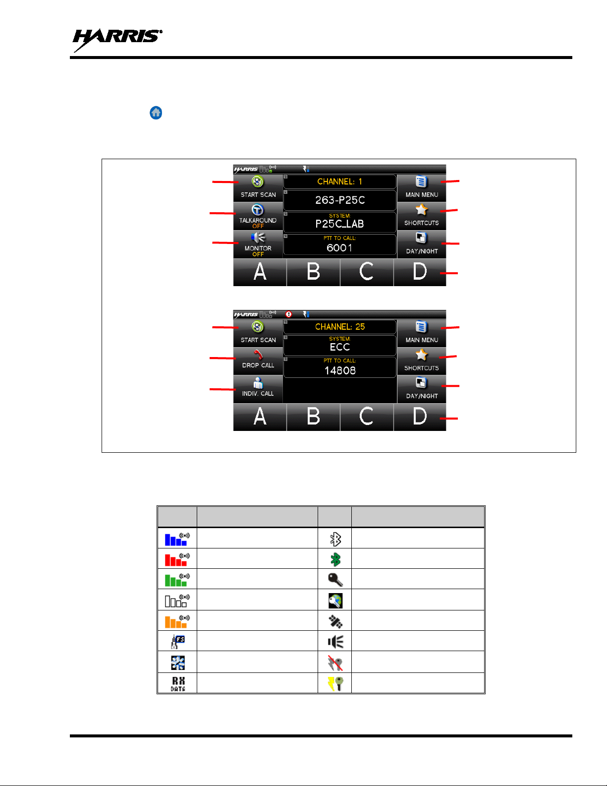
6.3 DISPLAY
The main display appears after power up or after exiting from the menus. While on the main display,
press the button to change its appearance.
To select an item, touch the desired area of the screen with your finger.
on and off.
monitor mode.
Figure 6-1: Conventional Display
Call.
menu.
Figure 6-2: P25 Trunked Display
Table 6-2 describes the various icons displayed by the radio. A description of these icons can also be
viewed via the Utility Menu. See Section 7.10 for more information.
Table 6-2: Icons
Trunked Signal Strength
TX Forward Power
Receive Signal Strength
Channel Idle
Transmitting Encrypted
Failsoft
Nuisance Channel
Receiving Data
Bluetooth On
Bluetooth Paired
Secure Traffic
Global Encryption
GPS Tracking
Monitor On
OTAR Disabled
OTAR Registered
15
Page 16
14221-1200-2010, Rev. E
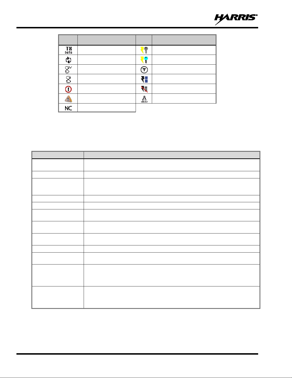
ICON
DESCRIPTION
ICON
DESCRIPTION
Noise Cancellation Enabled
queue is full, or an individual call is being attempted to a radio that is currently
Control Channel Scan mode to search for the control channel (usually out of range
Transmitting Data
Virtual Site
Vote Scanning
Scanning Enabled
Alert(s) Present
Emergency
6.4 STATUS MESSAGES
During radio operation, various rad io Status Messages may be display ed. The messages are described in
Table 6-3.
MESSAGE DESCRIPTION
PTT DENIED
CALL QUEUED P25 Trunked only - Indicates the s ystem has placed the call in a request queue.
SYSTEM BUSY
SCANNING Indicates the radio is scanning.
TX EMERGENCY P25 modes only - Indicates an emerge ncy call is being transmitted.
RX EMERGENCY
WIDE AREA SCAN
INVALID TALKGROUP
INVALID UNIT P25 Trunked only – Indicates the cur r ent unit is not valid for the current sys tem.
REGISTERING
CONTROL CHANNEL
SCAN
BAND SCANNING
P25 Trunked only - I ndicates the radio or talkgroup is not authorized to operate on the
selected system and/or talkgroup.
P25 Trunked only - Indicates the system is b usy, no channels ar e currently availa ble, the
transmitting.
P25 modes only - Indicates an emer gency call is being received. If program med via RPM ,
the radio will display the unit name or unit ID.
P25 Trunked only - Indicates the radio has enter ed the Wide Area Scan mode to search
for a new system (if enabled through programming).
P25 Trunked only - Indicat es the cur rent t alkgroup i s not va lid for the c urrent system. T his
could happen if the site denies regist r ation due to an unrecognized talkgroup ID.
P25 Trunked only - Displa yed when the radio is performing a registration/aff iliation on a
P25 trunking site.
P25 Trunked only - Indicates the control c hannel is lost and the radio has entered the
indication). The amo unt of ti me befor e the r adio enter s Contr ol Chann el Scan af ter losi ng
the control channel is configurable in RPM.
P25 Trunked only - This m essage is only displayed if the P25T system is configured f or
"EnhancedCC" mode of opera tion. W hen t he r adio ca nnot fi nd a Co ntrol Channel in eit he r
the trunked frequency set or t he list of discovered adjacencies, the radio is able to perform
a full spectrum frequency scan to f i nd a new Control Channel.
OTAR Registering
OTAR Rekeying
Talkaround Enabled
Transmit Power
RX Only
VDOC
Table 6-3: Status Messages
16
Page 17
14221-1200-2010, Rev. E
NOTE
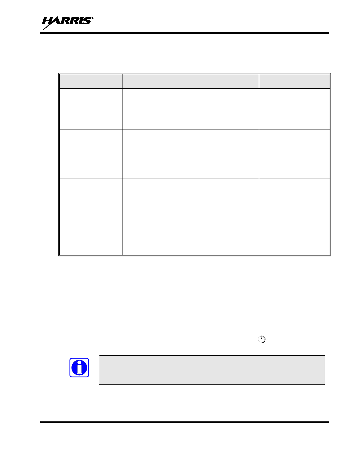
6.5 ALERT TONES
Table 6-4 describes the alert tones that may be played by radio.
TONE DESCRIPTION SOUND/DURATION
Table 6-4: Alert Tones
Ready To Talk Tone
Unencrypted (Analog FM
or P25 digital)
Ready to Talk Tone
Encrypted P25 digital
PTT Denied
Maximum transmit
duration expires
Emergency Call
Received
Out of Range Radio fails to find a local control channel.
After a PTT is pressed, this control enables the radio to
produce an audible indication (tone) for you to begin
speaking into the microphone.
After a PTT is pressed, this control enables the radio to
produce an audible indication (tone) for you to begin
speaking into the microphone.
PTT not possible. Momentary tone is pr esent:
• Receive only
• PTT button disabled
• Emerge ncy button disabled
• Emerge ncy not supported for current channel
• Clear transmit denied
Maximum transmit duration is exc eeded.
Radio is receiving an emergenc y call or priority call.
1000 Hz for 25 ms
1200 Hz tone for 25 ms
544 Hz tone for 75 ms
5 beeps and then a 544 Hz
tone for 75 ms
600 Hz tone for 250 ms and
1800 Hz tone for 250 ms
Programmable via RPM:
• Disabled (no tone)
• Slow (tone eve ry 15s)
• Medium (tone every 10s)
• Fast (tone every 5s)
6.6 BEFORE FIRST USE
Make sure the XG-100M has:
• Mission plan and radio programmed using the RPM
• Encryption keys loaded if using encrypted channels
• Mission plan activated
6.7 POWER ON AND SET VOLUME
The power switch and volume control are within the same control. Turn clockwise to power on
XG-100M and to set to desired volume level.
Minimum volume levels may be programmed into the radio to prevent missed calls
due to a low volume setting.
17
Page 18

14221-1200-2010, Rev. E
NOTE
6.8 CHANNEL PRESETS
Channel preset buttons are availab le on the st and ard s i ze scre en . P ress and hold one of the four buttons at
the bottom of the main display (Figure 6-3) to save the currently selected channel as a preset. Press this
button to quickly return to the preset channel.
Presets cannot be erased; they can only be p rogrammed with a new value. Channel
presets are lost when a new personality is activated.
Figure 6-3: No Channel Presets
6.9 NOISE CANCELLATION
The XG-100M features Harris’ proprietary noise suppression capability that provides clear and crisp
voice quality in high-noise environments in any mode, including analog and digital communications.
The XG-100M has two microphones; one located on the chorded microphone (Voice Microphone) and
one on the front of the control head (Noise Microphone). The Voice Microphone operates as the input
microphone for your voice. The Noise Microphone on the control head is used to pick up the surrounding
noise when noise cancellation is turned on. The control head should be mounted such that its Noise
Microphone element is unobstructed and exposed to the same ambient environment as your voice.
6.9.1 Enable Noise Cancellation
To enable noise cancellation:
1. From the main display, select the MAIN MENU.
Figure 6-4: Four Channel Presets
18
2. Select SETTINGS.
Page 19

14221-1200-2010, Rev. E
to toggle noise cancellation
3. Select AUDIO SETTINGS.
4. Select NOISE CANCELLATION
ENABLED or DISABLED. The icon is displayed in the top of
the display when noise cancellation is enabled.
6.9.2 Using Noise Cancellation
When using the noise cancellation feature, observe the following:
• Verify the NOISE CANCELLATION setting is enabled (see Section 6.9.1).
• Talk within two (2) inches of the Voice Microphone.
• Speak clearly, loudly, and with authority.
• Ensure that both the Voice Microphone and the control head’s Noise Microphone are not covered or
obstructed.
• In very noisy environments, it is okay to yell into the radio. The radio can handle very loud input
levels.
6.9.3 The Effect of Distance from the Microphone
Unlike a normal microphone system, noise can cellati on makes the level o f yo ur voice d iminish quickly as
you move the Voice Microphone away from your mouth. In essence, the radio starts to see your voice as
surrounding noise. Whereas you may be comfortable speaking up to a foot away from the Voice
Microphone on a normal radio, noise cancellation requires that you keep the Voice Microphone close to
your mouth. It is recommended that you hold the Voice Microphone within 2” of your mouth when
speaking.
6.9.4 Voice Mi crophone and Control Head Microphone Locations
The Voice Microphone is located on the front of the mic as shown in Figure 6-6. The Noise Microphone
on the control head is located on the left of the control head between the volume and channel knobs
(Figure 6-5). Every effort should be made to not obstruct either element during radio transmissions.
19
Page 20

14221-1200-2010, Rev. E
Figure 6-5: Noise Microphone
6.10 TURN ENCRYPTION ON OR OFF
Select MAIN MENU SECURITY ENCRYPTION to toggle encryption on and off.
Or
1. Select SHORTCUTS from the main display.
2. Select ENCRYPTION to toggle encryption on and off.
• A key appears on the display when encryption is enabled. The channel must also be programmed
to be encrypted.
• When encryption is turned on and you use any channel not configured for encryption, the radio
allows PTT. The signal is transmitted unencrypted.
• Channels configured for Global Encryption display a Global Encryption icon instead of key icon
(Section 7.1.4) if Global Encryption is enabled.
• Radios configured with Encryption Mode Forced On will have the Encryption menu item grayed
out with the state always ENABLED.
The radio can be programmed to allo w emergency calls to be transmit ted in the clear when the radio does
not have the key, or has an invalid key for the encrypted group in emergency.
Figure 6-6: Voice Microphone
20
Page 21

14221-1200-2010, Rev. E
FULL ACCESS
LIMITED ACCESS
RESTRICTED ACCESS
Audio Settings:
Touch Screen Tone
GPS Settings
Clock Settings
Bluetooth Settings
View Group List
Edit Group List
View Zone List
Edit Zone List
Zeroize
Keyset Changeover
Global Encryption
Global Key
Program Menu only in Active Mission Plan
P25 Test Selection on Utility Menu
6.11 USER INTERFACE PRIVILEGE LEVEL
Depending on radio programming, some of the menu options described in this manual may not be
available. The following table details the menus available for the different levels of User Interface
Privilege:
Figure 6-7: User Interface Privilege
Noise Cancellation
Master Volume Control
External Speaker
External Speaker Volume
MRU Volume
Accessory Power
6.12 SELECT CHANNEL
6.12.1 Select from Channel List
1. From the main display, select the channel name.
2. Select the desired channel from the list.
21
Page 22

14221-1200-2010, Rev. E
NOTE
6.12.2 Manually Enter Channel Number
To manually enter a channel:
1. From the main display, select SHORTCUTS.
2. Select ENTER CHANNEL NUMBER.
3. Enter the channel number and select OK.
Entering a number greater than the maximum numb er of entries in the selected zone will select the last
channel. From the radio’s perspective, channels entered in this manner are not treated any differently
from channels selected by the channel knob; for example, the scan list will be adjusted to add the channel
(and make it P1 if applicable), emergencies will go out on the entered channel, etc. The only invalid
channel is 0; if channel 0 is entered, the radi o plays a NAK tone.
Physically moving the channel knob or chang ing the system causes the radio to select
the channel in respect to the manually entered channel.
22
Page 23

14221-1200-2010, Rev. E
6.13 SELECT A ZONE/SYSTEM USING MENUS
A zone/system is a group of channels that can be programmed by agency or geographical region. For
example, a zone/system could be for fire, police, New York, Los Angeles, etc.
1. From the main display, select the zone/system name.
2. Select the desired zone/system from the list.
If is selected, a screen app ears allowing you to view th e channels
in the zone/system. Select ing a channel from the list will take you to
that channel.
A mission plan could have up to 512 zones/systems.
Or
6.14 VOICE ANNUNCIATION
1. From the main display, select MAIN MENU.
2. Select ZONES.
3. Select the desired zone/system from the list.
If is selected, a screen app ears allowing you to view th e channels
in the zone/system. Select ing a channel from the list will take you to
that channel.
A mission plan could have up to 512 zones/systems.
When enabled via programming, the Voice Annunciation feature provides audible feedback for various
radio operations. The radio can be programmed to play an audio message for any or all of the following.
This message can be a pre-recorded (canned) message or a user-recorded message.
23
Page 24

14221-1200-2010, Rev. E
and the
TALKAROUND button color is inverted from the home screen
now made on the receive frequency until you
NOTE
• Zone changes
• Channel changes
• System changes
• Encryption On/Off
• Monitor On/Off
• Noise Cancellation On/Off
• Scan On/Off
• Talkaround On/Off
• Tx Disabled On/Off
For more information on configuring the radio for Voice Annunciation, refer to the Voice Annunciation
Feature manual 14221-7200-6110.
6.15 USE TALKAROUND TO BYPASS REPEATER (ANALOG AND P25 CONVENTIONAL)
You can bypass the repeater system to co mmunicate directly with other rad ios on your current channel’ s
receive frequency. This is useful if you are out of range of a repeater or if a repeater is busy. You will
need to be in range of the other radio.
Or
1. From the main display, press and hold TALKAROUND for one
second to toggle talkaround on.
2. A tone sounds, the Talkaround icon appears
color. Calls are
disable Talkaround mode. Press and hold this button again to turn
Talkaround off.
Power cycling the radio does not disable Talkaround.
24
Page 25

14221-1200-2010, Rev. E
and the TALKAROUND button color is
. Calls are now made on the
NOTE
NOTE
1. From the main display, select MAIN MENU.
2. Select CALL.
3. Select TALKAROUND MODE to enable Talkaround mode.
4. The icon appears
inverted from the home screen color
receive frequency until you disable Talkaround mode.
Power cycling the radio does not disable Talkaround.
If the Talkaround Indication feature is enabled in RPM, the radio will play a unique grant tone when a call
is placed on a simplex channel or when Talkaround has been enabled on a duplex channel. This feature
applies to both Analog and P25 Conventional systems. It optionally allows the radio to also play the
same tone when it receives a call while operating in simplex or Talkaround. If configured, the radio
plays the tone at the selected volume level.
The tone will not play on systems configured for MDC or Type 99.
Talkaround Indication can be specified for each individual Analog and P25 Conventional system
configured in personality. The following options can be selected, and apply only when the radio is on a
simplex channel or when Talkaround has been enabled by the user:
• Disabled: (This is the default option.) When this option is selected, the rad io plays the standard grant
tone when a call is placed. The radio does not play a tone when a call is received.
• Transmit Only: When this optio n is selected, the radio plays a different “Talkaround” grant tone when
a call is placed. The radio does not play a tone when a call is received.
25
Page 26
14221-1200-2010, Rev. E
In the radio personality, the “Alert Tone” parameter needs to be enabled for each
5. Press PTT to make the call.
NOTE
• Transmit & Receive: When this op tion i s selected , the radio play s a diff erent “Talkaround” grant tone
when a call is placed, and at the beginning of a received call.
channel on the Conventional Frequency Set. The “Ready To Talk Tone” parameter
must also be enabled for the Talkaround Indication tone to be played when the radio is
keyed.
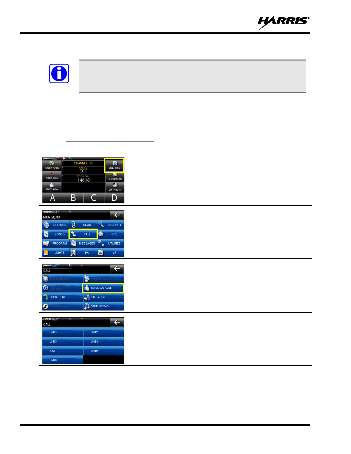
6.16 INDIVIDUAL CALLS
An individual call is used to make a call to one radio as opposed to a group of radios. An individual call
can only be made on a digital channel.
6.16.1 Transmit an Individual Call
1. From the main display, select MAIN MENU.
2. Select CALL.
3. Select INDIVIDUAL CALL.
4. Select the unit to call.
26
Page 27
14221-1200-2010, Rev. E
the calling
RPM.
an incoming Individual Call. The ring sounds continuously until
rop or terminate any
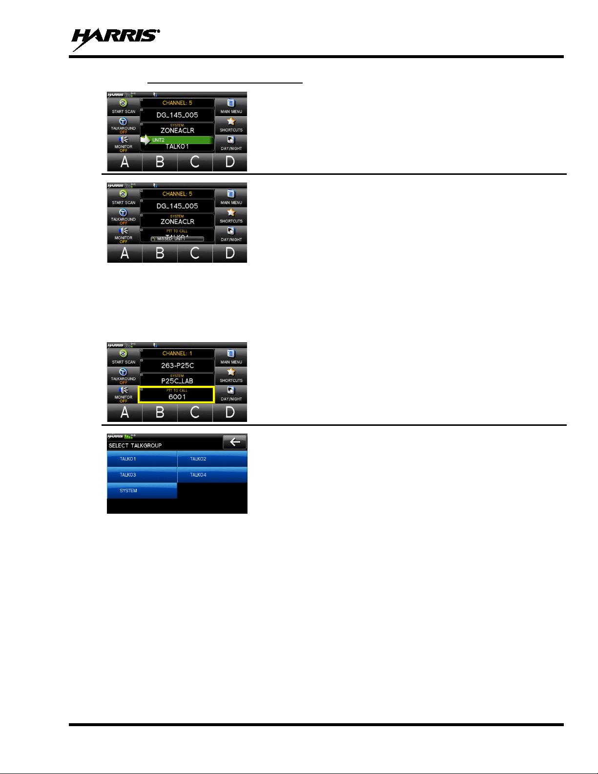
6.16.2 Receiving an Individual Call
6.17 GROUP CALLS
A talkgroup is a group of radios that you would want to have private conversations with. These groups
could be divided into areas such as state, region, county, or large special events. A group call can only be
made on digital channels. On the receiving radio, the calling station name appears in the activity area.
1. When receiving an Individual Call, the radio displays
radio’s name or Unit ID in the green RX banner and under PTT
TO CALL.
2. Press the PTT button to respond. The amount of time the radio will
remain in the Individual Call with no activity is programmable via
3. The radio rings and indicates a missed call if you do not respond to
you press PTT to answer the call, select t he missed call indication
to clear, or power cycle the radio.
1. From the main display, select the current talkgroup.
2. Select the desired talkgroup. After selecti ng the new talkgro up, the
radio returns to the main display.
3. Press PTT to make the call.
P25 Trunked Only: Press DROP CALL to d
group call that the radio receives.
27
Page 28
14221-1200-2010, Rev. E
After selecting the new
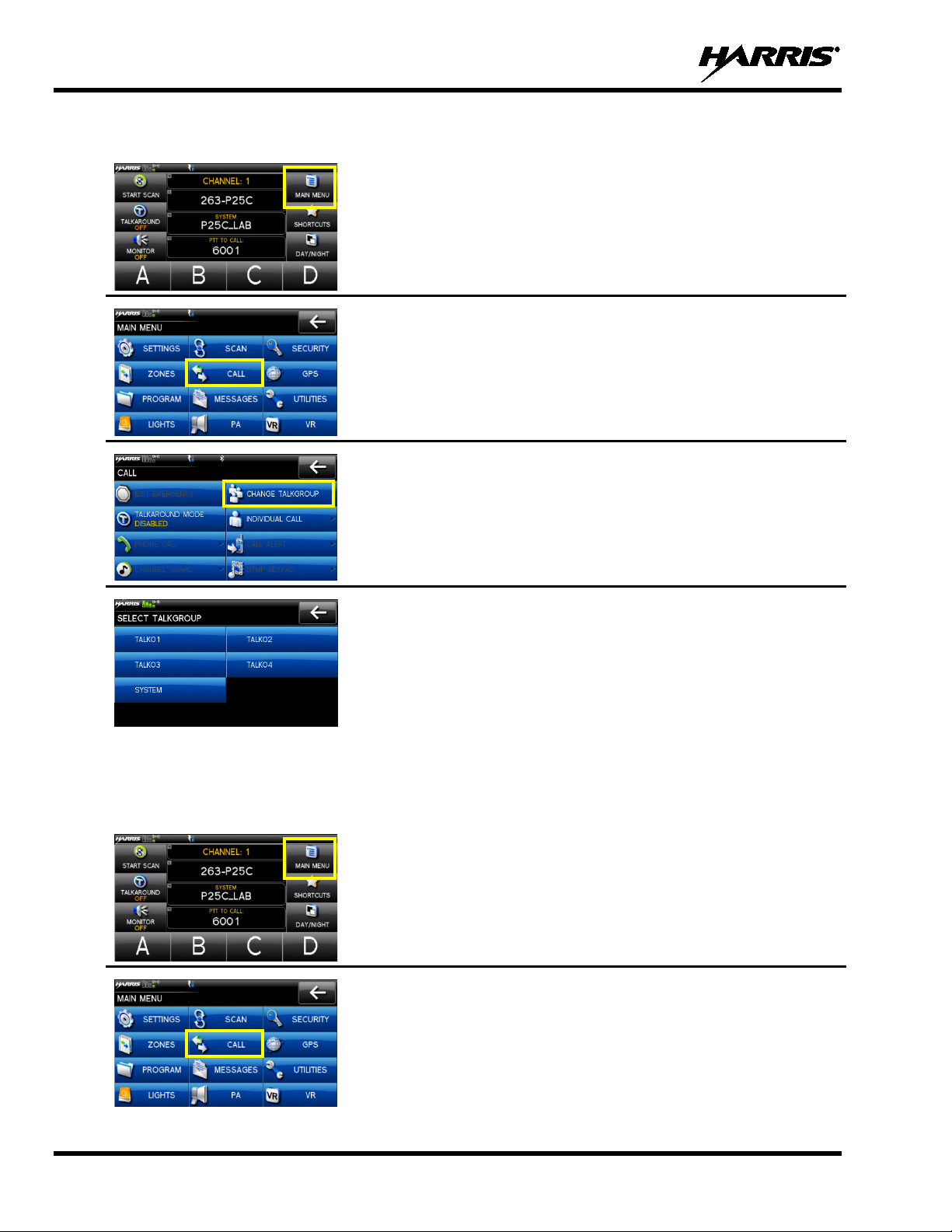
Or
1. From the main display, MAIN MENU.
2. Select CALL.
3. Select CHANGE TALKGROUP.
6.18 CALLER ID
This feature allows you to view the caller I D or alias for up to the last 10 recei ved calls. Received calls
include Group, Announcement, Phone, Patch, SimulSelect, Agency, Fleet, and MDC.
4. Select the talkgroup from the list.
talkgroup, the radio returns to the main display.
5. Press PTT to make the call.
1. From the main display, MAIN MENU.
2. Select CALL.
28
Page 29
14221-1200-2010, Rev. E
The most recent call is displayed at the top of the list. “NO
3. Select CALLER ID from the Call menu.
4.
ENTRY” is displayed if there are no entries.
The Caller ID list is cleared when power is cycled on the radio.
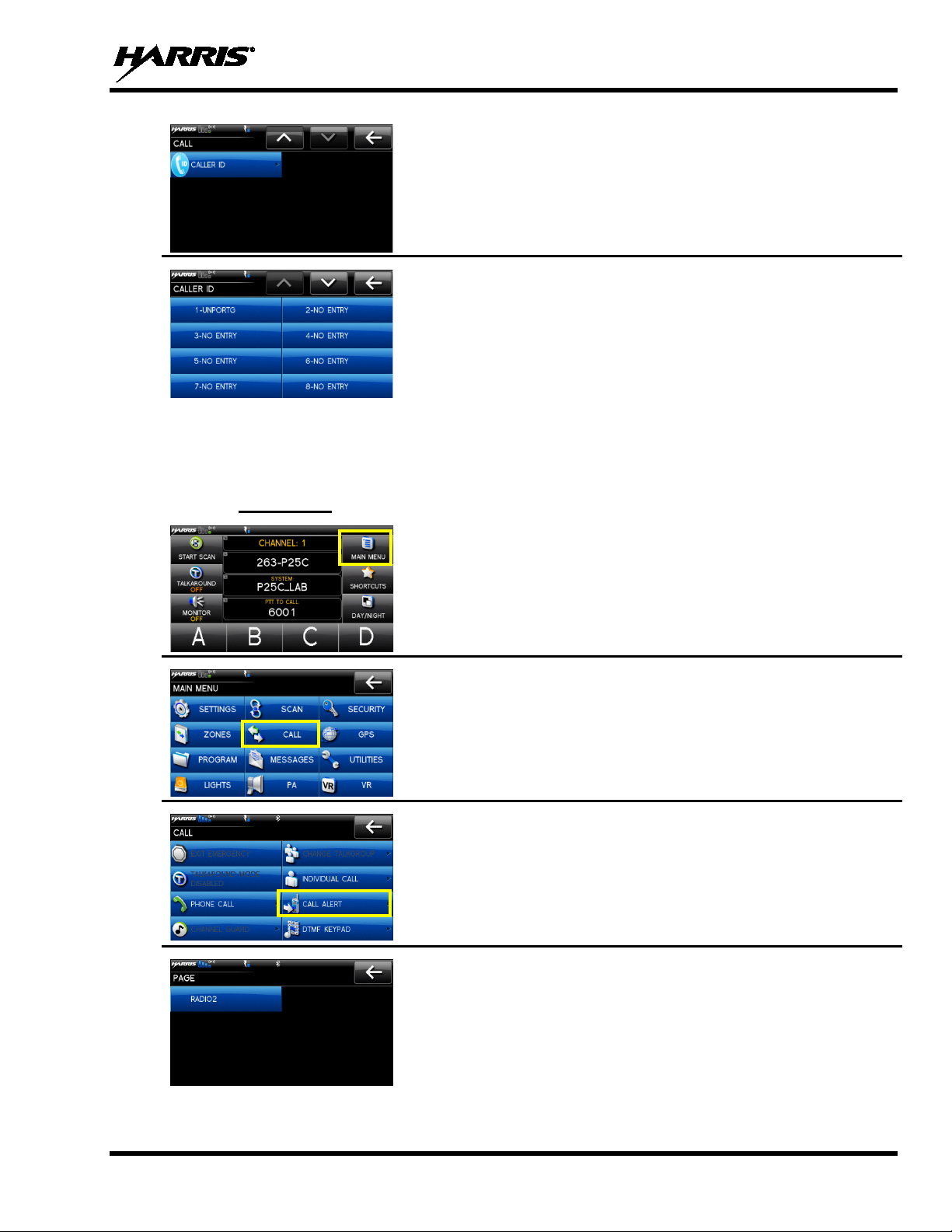
6.19 CALL ALERT (PAGE) - P25 TRUNKED ONLY
6.19.1 Send Alert
1. From the main display, MAIN MENU.
2. Select CALL.
3. Select CALL ALERT.
4. Select the desired unit from the list.
29
Page 30

14221-1200-2010, Rev. E
defined numbers for all
to enter the number directly.
9, *, #, or a
5. Press PTT to initiate the phone call.
5. Press PTT to send the page.
6.19.2 Receive Alert
When receiving a Call Alert, the radio displays the calling radio’s
name or Unit ID.
6.20 TELEPHONE INTERCONNECT
1. From the main display, select MAIN MENU.
2. Select CALL.
3. Select PHONE CALL.
4. Select SYSTEM LISTING to select from a list of pre-
programmed numbers for the active system, select USER
LISTING to select from a list of usersystems, or select DIRECT DIAL
Direct Dial entry can have up to 31 characters (0space; the space correlates to a pause.)
30
Page 31

6.21 DTMF
NOTE
The XG-100M supports the transmission of DTMF tones over the air and supports playing received
DTMF tones.
To access the DTMF keypad:
14221-1200-2010, Rev. E
DTMF tones will only play if the current sy stem is programmed for DTMF (part of
general System configuration).
1. From the main display, select MAIN MENU.
2. Select CALL.
3. Select DTMF KEYPAD.
4. Press and hold PTT while entering the number sequence from the
keypad.
31
Page 32

14221-1200-2010, Rev. E
, and the SCAN button color
6.22 SCAN OPERATION
6.22.1 Start Scan
This procedure assumes that the scan list h as been ad ded and is not i n acti ve sca n . Refer t o Section 7.8 for
scan setup or Section 6.22.2 for stopping scan. Refer to Section 7.8.1.1, Section 7.8.1.2, and Section
7.8.1.3 for home and priority channel descriptions.
1. From the main display, press and hold START SCAN for one
second.
2. A tone sounds, START SCAN text ch anges to red STOP SCAN,
and the SCAN button color inverts from the home screen color.
Or
1. From the main display, select MAIN MENU.
2. Select SCAN.
3. Select START SCAN. A tone sounds, the START SCAN button
text changes to red STOP SCAN
inverts from the home screen color.
32
Page 33

14221-1200-2010, Rev. E
button text changes to
6.22.2 Stop Scan
Perform the following to stop an active scan:
1. From the main display, press and hold STOP SCAN for
approximately one second.
2. The STOP SCAN text changes to START SCAN, and the SCAN
button color returns to normal.
Or
1. From the main display, select MAIN MENU.
2. Select SCAN.
3. Select STOP SCAN. The STOP SCAN
START SCAN, and the SCAN button color returns to normal.
33
Page 34

14221-1200-2010, Rev. E
NOTE
6.22.3 Nuisance Delete
A channel can temporarily be delet ed from the scan list. The currently selected channel, Priority 1, and
Priority 2 channels cannot be nuisance deleted.
Nuisance delete can only be performed on the active scan list.
1. From the main display, select SHORTCUTS.
2. Select NUISANCE DELETE.
NOTE: If the radio is not currently scanning, NUISANCE DELETE is
grayed out.
Or
1. From the main display, select MAIN MENU.
2. Select SCAN.
3. Select SYSTEM SCAN LISTS.
34
Page 35

14221-1200-2010, Rev. E
Select the desired channel. A pop is displayed. Select
Priority 1, and Priority 2
GPS has acquired satellite signal. GPS time
Radio was tracking and then lost GPS
4. Select next to the desired scan list.
5.
NUISANCE.
NOTE: The currently selected channel,
channels cannot be nuisance deleted.
6.23 VIEW GPS INFORMATION
Using an external GPS antenna, you can view your position and satellite information. GPS requires an
unobstructed view of the sky and the signal is greatly diminished inside buildings, tunnels, heavily
forested areas, etc. GPS may not work at all un der some materials, especially metal.
1. From the main display, select MAIN MENU.
2. Select GPS.
You can observe GPS status:
• DISABLED - GPS is disabled via programming.
• TRACKING -
appears on top of display.
• SEARCHING - GPS has not acquired.
• LAST KNOWN POS -
signal. The information displayed is from the last known position.
35
Page 36

14221-1200-2010, Rev. E
front of the control
is configured in RPM.
channel, which can get activated from analog or digital
also be programmed to send an Emergency
Alarm in addition to or in place of the emergency call (P25
The radio will go through transmit and receive cycles if
configured. Speak into the microphone while the radio is
3. Select to view satellite information.
4. Select to exit GPS screens.
6.24 EMERGENCY OPERATION
The XG-100M can be programmed to enable emergency mode. Unit name displays on dispatcher console
if an emergency signal is received from another XG-100M on a digital channel.
6.24.1 Declaring an Emergency Call
1. Press and hold the emergency button on the
head or hand-held controller. The length of time to hold the button
• For digital channels, the radio transmits the talkgroup or radio
ID to the dispatch console and receiving radio.
• The rad io can be programmed to have a dedicated emergency
channels.
• The radio can
modes).
•
transmitting or press PTT to talk.
2. To exit an emergency, power cycle the radio or select EXIT
EMERGENCY from the CALL menu.
36
Page 37

14221-1200-2010, Rev. E
ress PTT to respond to the
between the unit and talkgroup being received.
6.24.2 Receiving an Emergency Call
When receiving an Emergency Call, an alert beep sounds (if tones are enabled) and an emergency
indication is displayed.
Depending on options selected in RPM, the unit ID or unit name may
be displayed.
While the emergency display is active, p
emergency caller.
6.24.3 Stealth Emergency
The radio can be programmed with the following emergency behavior:
• No audio indications when declaring an emergency.
Or
• No visual indications when declaring an emergency.
Or
• No audio and no visual indications when declaring an emergency.
During stealth mode, the radio will not receive any typ e of call. Once the u ser presses the PTT bu tton, the
radio display and audio returns to normal.
6.25 ENCRYPTION BAR
The encryption bar is shown in Table 6-5. Encryption keys must be loaded (Section 7.1.2) for these
indications to be displayed.
Table 6-5: Encryption Bar Indications
DISPLAY DESCRIPTION
This is an example of a key name of an AES and a DES key being
transmitted or received.
Encryption key assigned to channel was not found.
This message appears on receive radios. Encryption key assigned to
channel was not used on transmitting radio. The green receive bar toggles
6.26 MDC-1200 (CONVENTIONAL ONLY)
MDC-1200 is a legacy in-band signaling protocol that provides the radio with the ability to transmit and
receive a unique PTT ID. This PTT ID can be decoded by receiving radios and displayed as a
hexadecimal number or an alias string. In addition, MDC-1200 provides radios with the ability to transmit
emergency status to a console.
Refer to the MDC-1200 Feature Manual, 14221-7200-6000, for complete instructions on configuring and
using this feature.
If MDC signaling on PTT press is en abled in RPM, the radio transmits an MDC PTT ID message when
PTT is pressed. If the Sidetone option is enabled in RPM, the radio plays a Ready-to-Talk (RTT) tone
after the MDC pre-signaling has been transmitted.
37
Page 38

14221-1200-2010, Rev. E
The options available depend on radio
programming.
NOTE
If MDC signaling on PTT release is en abled (in RPM), the radio transmits post-call MDC signaling when
PTT is released.
• IF STE is enabled (in RPM), the MDC post-call signaling is transmitted after STE is sent.
• MDC post-call signaling is also sent when there is a radio unkey due to Carrier Control Timeout
(CCT). Normal CCT alert tones occur prior to unkey.
6.27 LIGHTS AND SIRENS
The lights and sirens feature allows you to activate the siren/light combination defined for the
corresponding button. The siren and light functions are programmable v ia RPM for any combination of
siren and lights.
The Lights and Sirens feature requires an external lights and sirens controller.
1. From the main display, select MAIN MENU.
2. Select LIGHTS.
3. Select the desired option.
6.28 PUBLIC ADDRESS (PA)
To turn Public Address (PA) feature on/off and adjust the volume of the PA speaker:
1. From the main display, select MAIN MENU.
38
Page 39

14221-1200-2010, Rev. E
Allows you to manually
enter a channel number.
6.29 SHORTCUT MENU
2. Select PA.
3. Select PA ENABLED to d isable PA o r select PA DISABLED to
enable PA.
4. Use (+) or (-) to set the volume.
1. From the main display, select SHORTCUTS.
2. Select the desired task:
• DISPLAY LOCKOUT – Locks t he touch screen display. To
unlock, press the button.
• NUISANCE DELETE – Nuisance delete. This is grayed out
if not scanning or if the radio has declared an emergency.
• ENCRYPTION – Enables or disables encryp tion.
• DISPLAY ZONE NAME - Enable or disables the display of
the Zone name on the main display.
• ENTER CHANNEL NUMBER –
6.30 VEHICULAR REPEATER OPERATION
Refer to the VRS7000 Series Operator M anual (MM-018336-001) for detailed instructions on using the
XG-100M as part of the Vehicular Repeater System.
39
Page 40

14221-1200-2010, Rev. E
NOTE
NOTE
7. ADVANCED OPERATIONS
7.1 ENCRYPTION
7.1.1 Create Keys Using Harris Key Admin
Refer to the following documentation for advanced programming and setup instructions:
• Harris OTAR Overview Manual - MM-008069-001
• Network Key Manager Installation and Configuration Manual - MM-008070-001
• Harris UAS Key Management Application Manual - MM-008068-001
• Harris Key Manager Key Admin Overview and Operation Manual - MM1000019423
• Harris Key Manager Key Loader Overview an d Operation Manual - MM1000019424
• Motorola
• Motorola KVL 4000 Key Variable Load er (KVL) User's Guide
®
KVL 3000 Plus Key Variable Loader (KVL) User 's Guide
If using Key Manager to create and loa d keys, ensure that you have version R5A or
later installed. Versions prior to R5A do not support the Unity radio.
Harris Key Admin is part of the Harris Key Manager and is for use by the Crypto Officer (C O). The CO
creates a Master Set of keys from which a Distrib ution Set is produced. Using the Key Ad min software,
the CO can save keys into Distribution key files for technicians to use in radios.
1. Select Start Programs Harris Key Man ager Harris Key Admin.
2. Select New Master Set, Open, or Import from Security Device. Refer to the Key Admin online
help for more information on creating keys.
3. When finished, create a Distributio n Key File. A Distribution Key File is used with th e Key Loader to
load key sets into the radio and cannot be edited. Refer to the Key Admin online help for more
information on creating the Distribution Key File.
7.1.2 Load encryption Keys
7.1.2.1 Load UKEKS with Key Loader and RPM ( for OTAR-Enabled Systems)
UKEKs are loaded into Harris OTAR radios using the Key Loader application. Key Loader is a part of
Key Manager.
To load encryption keys:
1. Obtain the UKEK file and Storage Location Number (SLN) Binding Report information from the
Crypto Officer (CO).
Both AES and DES UKEKs can be contained wi thin the same UKEK file
40
2. If not already on, power-up the PC that has RPM and the Key Loader applications installed on it, and
start Windows
®
.
Page 41

14221-1200-2010, Rev. E
NOTE
3. Connect the radio to the PC using a USB cable (type A male to mini-type B).
The Unity drivers must be installed before UKEKs can b e loaded into the radio. The Unity
drivers may be found on the Key Loader CD (“unity setup.exe”) or on the Key Admin CD
(“unity setup.exe”).
4. Load the UKEK file from the Crypto Officer on t o the PC.
5. Run the RPM application and setup the radio’s Mission Plan according the SLN Binding Report
information.
6. Setup the talk groups and the SLN mappings (Talk Group ID to SLN). This includes mapping SLNs
to the “System” keys (PSTN, All Call, etc.).
7. Select Options
P25 OTAR Options and set the following:
a. The OTAR Message Number Period (MNP) as defined by the System Administrator.
b. The radio’s Individual RSI (from the SLN Bindings Report).
c. The KMF’s RSI (from the SLN Bindings Report).
8. Program the Mission Plan to the radio.
9. Run the Key Loader application.
10. Open the UKEK file loaded in step 4.
11. Select the Target Devi ce t ype and click the Load button.
12. The Key Loader reads the target device’s identifying information, retrieves a UKEK of th e proper
algorithm type from the UKEK file, and downloads the UKEK to the target device at the proper SLN
and keyset with the proper key ID.
13. Click the Finish button to exit the Key Loader application. New UKEKs have are loaded and the
radio is now ready to accept TEKs via OTAR with the tr unked radio network.
7.1.2.2 Load Keys Using Harris Key Loader
Harris Key Loader is part of Harris Key Manag er and can be used by the Crypto Offic er or Techn ician to
load the keys into the Unity radio.
Refer to the Harris Key Loader online help if additional information is required when performing this
procedure.
1. Connect the radio to the PC using a USB cable (CH-100) or serial cable (MRU).
2. Power on the radio, if not already.
3. On the radio, select MAIN MENU
4. On the PC, select Start
Programs Harris Key Manager Harris Key Lo ad er.
5. At the Key Loader Welcome screen, click Next.
6. Select Load a Distribution Set into one or more devices.
7. Click Next.
SECURITY HARRIS KEYFILL (SERIAL PORT).
8. Browse to the Key File and enter the password.
9. Click Next to validate the password an d continue. If the password is inco r rect, the screen will display
an error message.
41
Page 42

14221-1200-2010, Rev. E
NOTE
10. Select USB from the drop-down and click Next.
11. Select the Unity radio from the drop-down and click Load.
12. Click Finish.
7.1.2.3 Load Keys Using Motorola KVL Device
Type 3 Digital Encryption Standard Output Feedback (DES-OFB) and Advanced Encryption Standard,
256-bit (AES-256), encryption methods are supported. The Type 3 Encryption keys are loaded via a
Motorola KVL 3000 Plus device using Telecommunications Industry Association (TIA)/Project 25 (P25)
key fill device protocol. Make sure that valid keys have been created and stored in the KVL Device
before proceeding.
1. Power on the KVL Device.
2. Connect the KVL Device to XG-100M using cable 12099-0410-A1.
Once the KVL 3000 Plus is connected, a keyset is established whether the keys are
loaded or not. You will need to zeroize to bring the XG-100M to a fully zeroized state
(Section 7.1.3).
3. At the radio, select MAIN MENU SECURITY OTHER KEYFILL. The KEYFILL
SCREEN is displayed. The radio can no w accept keys from the KVL.
7.1.3 Zeroize Al l f r om Radio
It may be necessary to remove the keys because o f compromise or expiration.
1. From the main display, select MAIN MENU.
2. Select SECURITY.
3. Select ZEROIZE KEYS.
42
Page 43

14221-1200-2010, Rev. E
4. Select YES if you want to remove the keys and keysets.
7.1.4 Protect ed Keys
The Protected Keys feature transfers P25 Voice Keys, from Harris Key Loader to the radio, that have
been wrapped (AES) or encrypted (DES) with Key Protect ion Key s (KPKs). KPKs are noth ing more than
unprotected Key Encryption Keys (KEKs). The KPKs need to be loaded into the radio before the
Protected Keys are loaded. Once loaded into the radio, the KPKs will be used to unwrap (AES) or decrypt
(DES) the Protected Keys.
The radio must be placed into the key loading mode (see Section 7.1.2.2) in order to accept the KPKs and
P25 Voice Keys.
7.1.5 Global Encryption
When Global Encryption is enabled on the radio, Global Key is used for all encrypted transmissions until:
• Global Encryption is disabled.
• A new mission fill is activated.
• The active keyset is changed.
• The system is changed.
Global Encryption behavior is available on all channels that support encrypted communications.
1. From the main display, select MAIN MENU.
2. Select SECURITY.
43
Page 44

14221-1200-2010, Rev. E
The numbered keys are assigned in
6. The global key icon is displayed on the main display.
3. Select GLOBAL ENCRYPTION to toggle to ENABLED.
4. Select GLOBAL KEY.
5. Select the desired global key.
RPM.
7.1.6 Select Keyset
1. From the main display, select MAIN MENU.
2. Select SECURITY.
3. Select ACTIVE KEYSET to toggle to the inactive keyset.
44
Page 45

14221-1200-2010, Rev. E
to request that the KMF updates the k eys in
7.1.7 OTAR Conf iguration
OTAR is the over the air rekeying from a KMF and must be enabled for the digital only channel using
RPM. For OTAR operation, the appropriate KEKs must be loaded into the radio using the Harris Key
Loader or a KVL device.
The KMF Configuration must include the RSI of the KMF and the appropriate Message Number Period.
1. From the main display, select MAIN MENU.
2. Select SECURITY.
3. Select OTAR to toggle between ENABLED or DISABLED.
4. Select OTAR REKEY
the radio.
7.2 ACTIVATE/VIEW MISSION PLAN
Mission plans contain radio programming information such as frequencies, channels, stations, and talk
groups. Up to 10 different mission plans can be stored in the radio, but only one can be activated at a
time.
1. From the main display, select MAIN MENU.
2. Select PROGRAM.
45
Page 46

14221-1200-2010, Rev. E
to open a popup with the options
is activated, the radio displays series of screens indicating
You cannot activate a plan when the radio is
message may be displayed for errors
such as invalid syntax in the fill or some other invalid parameter.
NOTE
NOTE
3. Select a mission plan
ACTIVATE PLAN, VIEW PLAN INFO, or CANCEL.
4. indicates the active mission plan.
If a plan
status. When complete, the radio returns to the main display.
transmitting an emergency.
A MISSION PLAN FAILED
7.3 USER-DEFINED ZONES/SYSTEMS
7.3.1 Command Tactical Zone
The Command Tactical Zone is defined “on-the-fly” at the radio.
A Command Tactical Zone is reset when a Missi on Plan is activated.
To create or edit a Command Tactical Zone:
1. From the main display, select MAIN MENU.
2. Select ZONES.
46
Page 47

14221-1200-2010, Rev. E
and/or channels
Command Tactical
Zone. You cannot clear a zone if it is active.
3. Select next to <USER-DEFINED>.
• Select EDIT ZONE to create/edit a Command Tactical Zone.
• Select VIEW ZONE to view the groups
included in the Command Tactical Zone.
• Select RENAME ZONE to rename the
Zone (up to 16 characters are allowed).
• Select CLE AR ZONE to clear an existing Command Tactical
4. From the EDIT menu, select the system.
5. Select the desired channel/group. Select
7.3.2 Mixed System/Zone
Mixed System Zones are defined in RPM and cannot be edited on the radio. If a Mixed System Zone is
not configured in RPM, it will not appear on the radio. Up to 50 Mixed System Zones can be defined.
On the ZONE/SYSTEMS screen, mixed Systems/Zones are indicated
by the icon.
47
Page 48

14221-1200-2010, Rev. E
7.4 MIXED ZONE SCAN
The Mixed Zone Scan (MZS) feature gives the u ser the capabi lity to scan based on a custo m scan list that
is assigned at the system level. The Custom Scan (CS) list can contain System and Channel/Group
configurations across P25 Trunk, P25 Conventional, and Analog Systems. When a Custom Scan List is
defined on a P25T system, the radio can scan P25T, P25C and Analog systems. When defined on a P25C
or Analog system, the radio only scans conventional channels. MZS also gives the user th e capability to
scan beyond the selected system group set.
• P25T Scan
When a custom scan list is assigned to a P25 T system, the user has the ability to scan P25T, P2 5C,
and Analog groups/channels. All P25T systems must have the same WACN, System ID, and Unit I D
to be added to the custom scan list.
• P25C and Analog Scan
When a custom scan lists is assigned to a P25 C or Analog System, the user has the ability to scan
P25C and Analog channels. P25T systems are ignored.
7.4.1 Creating Custom Scan Lists
Custom Scan Lists can be created or deleted through RPM only. The radio supports up to 10 Custom
Scan lists, with up to 50 channels/groups in each.
7.4.2 View/ Edi t Custom Scan Lists
Custom scan list can be viewed/edited in RPM o r at the radio.
To create a custom scan list at the radio:
1. From the main display, select MAIN MENU.
2. Select SCAN.
3. Select CUSTOM SCAN LISTS.
48
Page 49

14221-1200-2010, Rev. E
systems are displayed. Systems that do not have
groups/channels currently included in the custom scan list are
you can
4. Select next to an existing scan list.
5. Select VIEW/EDIT LIST.
6. Available
grayed out. Select the desired system.
7. The system’s groups/channels are displ ayed. Channels/groups not
included in the custom scan list are grayed out.
8. Select a channel/group. From the displayed dialog,
add/delete the channel/group and change the priority level.
49
Page 50

14221-1200-2010, Rev. E
the desired
next to the system name indicates a
7.4.3 Custom Scan List Selection
The Custom Scan List is assigned at the System level. Scanning protocols (Custom Scan, System Scan,
and Conventional Priority Scan) are mutually exclusive. Once a custom scan list is assig ned to a system,
when you enable scan, you are scanning the channel/groups defined in the custom scan list. A C ustom
Scan List can be assigned to a system through RPM or at the radio via the CH-100 control head. The
radio supports up to 10 Custom Scan lists, with up to 50 channels/groups in each.
To assign a custom scan list to a system at the radi o:
1. From the main display, select MAIN MENU.
2. Select SCAN.
3. Select CUSTOM SCAN ASSIGN.
4. On the SET CUSTOM SCAN LIST screen, select
system from the list.
custom scan list is assigned to the system.
5. On the CHOOSE SCAN LIST screen, select the desired scan list.
50
Page 51

14221-1200-2010, Rev. E
select the channel to display the channel
7.5 CH INFORMATION MENU
The Channel Information (CHANNEL INFO) menu displays information about the currently selected
channel. Note that the information displayed varies between conventional and trunked systems.
1. From the main display, select the channel to display the channel
information.
2. Additional settings can be found by scrolling down.
7.6 EDIT CHANNEL (ANALOG AND P25 CONVENTIONAL ONLY)
Channels can be edited from the Channel Information (CH INFO) menu display if enabled via
programming. Most of the displayed channel parameters can be modified here. Channel edits persist
across a power cycle. Loading a mission plan clears any channel edits. Available parameters vary
depending on whether the channel is a digital or analog channel.
1. From the main display,
information.
2. Select EDIT CHAN.
3. Enter the password programmed via RPM.
51
Page 52

14221-1200-2010, Rev. E
for more information on the available
4. Edit parameters as necessary. Refer to Maintenance Manual
14221-1200-5000 for a full description of the available parameters.
7.7 SETTINGS MENU
The settings menu allows you to change global radio settings such as audio, display, GPS, Bluetooth,
clock, and battery settings.
1. From the main display, select MAIN MENU.
2. Select SETTINGS.
Refer to the Section 7.7.1
settings.
52
Page 53

14221-1200-2010, Rev. E
Enable or disable noise
Noise cancellation reduces background noise
the external
When enabled, a tone sounds
Enable or disable the master
. When disabled, the volume knob on a remote mount
MASTER VOL
3. Use to exit menu.
NOTE
7.7.1 Audio Sett i ngs
Set audio settings such as noise cancellation, master vol. control, external speaker, external speaker
volume, MRU Volume, accessory power, touch screen tones.
1. From the Settings Menu, select AUDIO SETTINGS.
2. Select and change settings as desired:
• NOISE CANCELLATION -
cancellation.
during transmit.
• EXTERNAL SPEAKER - Enable or disable
speaker.
• MRU VOLUME – Adjust the radio volume.
• TOUCH SCREEN TONE –
when an option is selected from the touch screen .
• MASTER VOL CONTROL –
volume control. When enabled, it allows remote control heads
to control the volume of the speaker attached to the back of the
MRU
control head only controls the volume of the speaker attached
to the control head.
• EXT. SPEAKER VOL – Adjust the external speaker v olume.
• ACCESSORY POWER – Turn accessory power on or off.
In front mount configurations,
CONTROL and MRU VOLUME are not available.
53
Page 54

14221-1200-2010, Rev. E
Set unit of measurement of displayed
Set unit of measurement of displayed
Set format of displayed position
information: Latitude/Longitude Degrees Minutes Seconds
tary Grid
(UTM).
7.7.2 Display Settings
1. From the Settings Menu, select DISPLAY SETTINGS.
2. Select and change settings as desired.
7.7.3 GPS Settings
1. From the Settings Menu, select GPS SETTINGS.
2. Select and change settings as desired:
• LINEAR UNITS linear units: STATUTE, METRIC, or NAUTICAL.
• ANGULAR UNITS angular units: CARDINAL, DEGREES, or MILS.
• POSITION FORMAT-
(LAT/LONG DMS), LAT/LONG DM, Mili
Reference System (MGRS), or Universal Transverse Mercator
54
Page 55

14221-1200-2010, Rev. E
to delete all paired
Make sure device being paired is powered on and has discovery
7.7.4 Bluetooth
Bluetooth settings only appear if enabled in RPM.
1. From the Settings Menu, select BLUETOOTH SETTINGS.
2. Select ENABLED to toggle between YES (enabled) and NO
(disabled).
3. Select PAIRED DEVICES to view all Bluetooth devices currently
paired with the radio.
4. Select to delete a device. Select
devices.
5. Select FIND DEVICE. This is used to pair the radio with another
Bluetooth device.
6.
mode enabled to pair the device with the XG-100M.
7. Select the desired device.
55
Page 56

14221-1200-2010, Rev. E
You will also need to accept the passkey on the
. This is the Bluetooth name assigned
turn on discovery mode so other
NOTE
NOTE
For Bluetooth 2.0 devices, a pin code screen appears.
8. Enter pin code.
9. Select OK.
For Bluetooth 2.1 devices, an accept/deny screen appears.
10. Select ACCEPT.
Bluetooth 2.1 device.
A message appears when pairing is complete.
11. Select OK. The paired device is then displayed under the paired
devices list.
Names containing extended ASCII characters may not
display correctly
12. Select FRIENDLY NAME
to the radio. The friendly name programmed by RPM will
overwrite this setting.
13. Enter the name from the keypad displayed on the touch screen and
select DONE when finished.
14. Select DISCOVERABLE to
Bluetooth devices can discover the XG-100M.
56
Page 57

14221-1200-2010, Rev. E
Set time zone relative to Universal Time
7.7.5 Clock Sett i ngs
15. Select OK. Discovery mode will be enabled for two minutes.
16. The DISCOVERABLE menu item turns red for the two minutes
that Discovery mode is enabled.
1. From the Settings Menu, select CLOCK SETTINGS.
2. Select the setting to change.
• DISPLAY TIME - Set 12 or 24 hour time display format.
• TIME ZONE -
Coordinated (UTC).
57
Page 58

14221-1200-2010, Rev. E
NOTE
7.8 SET UP SCAN
These procedures are used to set up the scan list , home channels, and priority channels. Refer to 6.18.
1. From the main display, select MAIN MENU.
2. Select SCAN.
3. Refer to the information in Sections 7.8.1 through 7.8.5.
When using Preemptive Priority Scan, the frequencies in the list need to be unique.
7.8.1 Home, Pri or ity 1, and Priority 2 Channels
7.8.1.1 Home Channel
This is the channel you transmit on by default when you press PTT while the radio is actively scanning
and is not responding to a just received call. Responding to a call the radio just received while scanning is
called hang time. If hang time is set to 0 in RPM, the radio always transmits on the home channel in scan.
7.8.1.2 Priority 1 Channel
This channel will be scanned more often than oth er channels in the list and will be scanned in between
every other channel in the scan list. An ex ample scan sequence wou ld be P1 (priority 1), C2, P1, C3, P1,
C4, etc. Also, the priority channel will be scanned even while actively receiving on a non-priority
channel. For example, if the radio is actively receiving on C3 and activity is detected on P1, the radio will
drop C3 and switch to P1.
58
Page 59

14221-1200-2010, Rev. E
NOTE
NOTE
7.8.1.3 Priority 2 Channel
This channel will also be scanned more often than others. An example scan sequence would be P1, C2,
P1, C3, P1, C4, P2, C5, P1, C6, P1, C7, P1, C8, P2, C9 etc. Also, this channel will be scanned ev en while
actively receiving on a non-priority channel. For example, if the radio is actively receiving on C3 and
activity is detected on P2, the radio will drop C3 and switch to P2. Additionally, activity on P1 preempts
P2, but P2 cannot preempt P1.
7.8.2 Trunked/Conventional Scanning
Trunked/conventional scanning adds the ability to scan multiple conventional and P25 conventional
channels while still maintaining P25 trunked radio operation. In essence, the radio is able to scan a
conventional scan list while still receivi n g a P2 5 t runked control channel and receiving P25 trunked calls.
Selection of which conventional scan list is associated with a given trunked system is done in RPM and
cannot be changed on the radio. However, a user with sufficient UI privilege level (see Section 0) is
allowed to edit the scan list members (both trunked groups and conventional channels on the selected
Conventional Priority System). As the number of conventional channels being scanned increases, the
time between scanning each channel increases (roughly 250 milliseconds per channel), with the
consequent increase in the number of calls that will late-enter. In order to avoid missing calls, it is
recommended to keep the number of conventional channels being scanned to eight (8) or fewer.
The trunking site must have roaming set to Enhanced CC.
7.8.3 Vote Scan (Analog and P25 Conventional Only)
If Vote Scan is enabled via RPM, the radio automatically selects the strongest signal ensuring that the best
audio quality is delivered to the user. If Vote Scan is enabled, the radio is alway s scanning. You cannot
stop scanning, start normal scanning, or monitor the channel. There is an icon in the upper status bar
indicating that the radio is Vote Scanning.
If Talkaround is enabled, Vote Scan is turned off.
59
Page 60

14221-1200-2010, Rev. E
ZONE LIST.
7.8.4 Set or Remove Priority 1 and Priority 2 Channels
Priority channels are scanned more often than non-priority channels. Note that P1 can be configured via
RPM as “Keypad,” “Fixed,” or “Selected. ”
P2 can be configured via RPM as “Keypad” or “Fixed.”
Zone scan configuration screens are shown below. Group scan configuration is similar.
1. Enter Set up Scan (see Section 7.8) and select GROUP LIST or
2. Select next to the name of the scan list.
3. Select the desired channel.
4. Select SET PRIORITY 1, SET PRIORITY 2, DELETE
CHANNEL, NUISANCE or CANCEL.
7.8.5 Wide Area System Scan (P25 Trunked Only)
Wide Area System Scan (WASCAN) causes the radi o to roam across mobile systems when the currently
selected system's control channel is lost . The radio will scan the control channels of other systems.
1. From the main display, select MAIN MENU.
60
Page 61

14221-1200-2010, Rev. E
7.9 MESSAGE MENU
7.9.1 Radio Stat us
2. Select SCAN.
3. Select SITE ROAMING to toggle Wide Area System Scan
ON/OFF.
The status feature is used to send a particular status condition to the site without making a voice call.
There can be up to 10 status conditions programmed into the radio. For each status defined, there is an ID
and an alphanumeric name. The ID is sent to the site and the alphanumeric name appears on the radio
display when the ID corresponds with the information programmed at the site.
1. At main display, select MAIN MENU.
2. Select MESSAGES.
3. Select RADIO STATUS.
61
Page 62

14221-1200-2010, Rev. E
icon changes to an arrow to
indicate active status after the status has been sent and is
icon changes to an arrow to
indicate active status after the message has been sent and is
4. Select desired message. The
acknowledged by the site.
7.9.2 Radio Message
The message feature is used to send a p articular message to the site without making a voice call. Th ere
can be up to 10 messages programmed into the radio. For each message defin ed, there is an ID and an
alphanumeric name. The ID is sent to the site an d the alphanumeric name appears on the radio display
when the ID corresponds with the information programmed at the site.
1. At main display, select MAIN MENU.
2. Select MESSAGES.
3. Select RADIO MESSAGE.
4. Select the desired message. The
acknowledged by the site.
62
Page 63

14221-1200-2010, Rev. E
7.9.3 Radio TextLink (P25 Trunked Only)
Radio TextLink provides short text messaging functionality for radios. Because of the difficulty of
entering text messages on a radio, p redefined "canned" messages and predefined replies can be stored in
the radio. To facilitate sending messages where information must be provid ed at send time, text messag e
forms will also be stored in the radio. A form contains up to four (4) text prompts, for which the operator
enters alphanumeric values before sending the message.
7.9.3.1 Radio TextLink Messages
1. At main display, select MAIN MENU.
2. Select MESSAGES.
3. Select TEXTLINK MSGS.
4. Select the desired message.
5. Select SEND t o send the message, or select CH ANGE CALLEE
to change message destination.
63
Page 64

14221-1200-2010, Rev. E
7.9.3.2 Radio TextLink Forms
Form messages are displayed and stored in the radio as a message in which each field to be filled is
indicated by a question mark (?) followed by one or more asterisks(*). Th e number of asterisks indicates
the maximum number of alphanumeric characters allowed for that field.
1. At main display, select MAIN MENU.
2. Select MESSAGES.
3. Select TEXTLINK FORMS.
4. Select the desired form.
5. Enter text into blank field(s) (up to 8 alpha-numeric characters).
6. Select SEND to send the message. Select CHANGE CALLEE to
change the message destination.
64
Page 65

14221-1200-2010, Rev. E
7.9.3.3 View Received Messages
When the icon appears on main display, there are Radio TextLink messages waiting to be read.
1. At main display, select MAIN MENU.
2. Select MESSAGES.
3. Select RX TXTLNK MSGS.
7.9.4 Faults/Alerts
If the alert icon is displayed on the main display, you can view details about the alert from the
MESSAGES MENU:
1. From the main display, select MAIN MENU.
2. Select MESSAGES.
65
Page 66

14221-1200-2010, Rev. E
3. Select FAULTS/ALERTS.
4. Observe messages in display. deletes all messages.
deletes the selected message.
NOTE: The alert icon goes away when you go to the message display
(unless a new fault occurs).
7.10 UTILITIES MENU
1. From the main display, select MAIN MENU.
2. Select UTILITIES.
3. Select RADIO INFO to view radio information such as software
and firmware revisions.
4. Observe the RADIO INFO display.
66
Page 67

14221-1200-2010, Rev. E
to view the features enabled on the
6. Select SERIAL PORT MODE to specify ASCII o r MDT.
descriptions of the icons
enabled via programming and requires a password to access the
From this screen, you can select a pattern test or
Refer to Maintenance Manual
RSSI screen and in the bottom right
5. Select FEATURE INFO
radio.
7. Select ICON GLOSSARY to view
displayed by the radio.
8. Select TESTS. Note that this option is only available when
available tests.
IBER (modulation) test to run.
14221-1200-5000 for more information.
9. Select RSSI. En able or Disable DISPLAY RSSI. When enabled,
RSSI is displayed on the
corner of the main display.
7.11 OTAP
Radios with R3A and later software support Over-the-Air-Programming (OTAP) via ProFile Manager.
RPM creates, modifies and stores perso nality informatio n while ProFile Manag er delivers the p ersonality
over the network to the desired radios. ProFile Manager also contains the ability to read personality
information over-the-air and save the files, so that RPM can modify the information if necessary.
Interrupt the programming process, if necessary, by depressing the Push-to-Talk (PTT) button or
declaring an emergency. Once a radio personality update is successfully completed, the radio
automatically resets itself, switches to the new personality, and returns to normal operation.
For more information on using ProFile Manager, refer to software release notes AE/LZT 123 3263/1.
7.12 PPP/SLIP
The radio can be configured to act as a Mobile Data Terminal (MDT). An M DT is essentially a portable
computer capable of transmitting data messages vi a an RF communications link. Refer to Appendix A for
instructions on how to setup PPP and SLIP connections between the radio and a Mo bile Data Peripheral
(MDP).
67
Page 68

14221-1200-2010, Rev. E
Table 8-1: Marine Frequencies
CHANNEL
FREQUENCY
SHIP
(MHZ)
SHORE
(MHZ)
1 1
T: 156.05
R: 160.65
T: 160.65
R: 156.05
International: Public Correspondence, Port Operations
1a
T/R:
156.05
T/R:
156.05
US: Port Operations and Commercial, Vessel Traffic Service (VTS). New
Orleans/Lower Mississippi area.
2 2
T: 156.10
R: 160.70
T: 160.70
R: 156.10
International: Public Correspondence, Port Operations
3 3
T: 156.15
R: 160.75
T: 160.75
R: 156.15
International: Public Correspondence, Port Operations
4
T: 156.20
R: 160.80
T: 160.80
R: 156.20
International: Public Correspondence, Port Operations
4a
T/R:
156.20
T/R:
156.20
Canada: Department Fisheries Oc ean (DFO)/Canadian Coast Guard only in
British Columbia coast area. Commercial fishing in east coast area
5
T: 156.25
R: 160.85
T: 160.85
R: 156.25
International: Public Correspondence, Port Operations
5a 5a
T/R:
156.25
T/R:
156.25
US: Port Operations or VTS in Housto n, New Orleans and Seattle areas.
6 6 6
T/R:
T/R:
US: Intership Safety
and aircraft.
7
T: 156.35
R: 160.95
T: 160.95
R: 156.35
International: Public Correspondence, Port Operations
7a 7a
T/R:
156.35
T/R:
156.35
US: Commercial
8 8 8
T/R:
T/R:
US: Commercial (Intership only)
Canada: Also assigned for intership in the Lake Winnipeg area.
9 9 9
T/R:
T/R:
US: Boater Calling. Commercial and Non-Commercial.
maritime support operations.
8. REFERENCE
8.1 MARINE FREQUENCIES
Refer to Table 8-1: Marine Frequencies for a list of maritime frequen cies per United States Coast Guard
(USCG), National Oceanic and Atmospheric Administration (NOAA), and Canadian Department
Fisheries and Oceans, August 2009:
• United States (US)
• International (Intl)
• Canada (CA)
US INTL CA
156.30
156.30
CHANNEL USAGE
International: Intership
Canada: May be used for search and rescue communications between ships
156.40
156.45
68
156.40
156.45
International: Intership
International: Intership, Por t Operations
Canada: Commercial - British Colum bia coast area.
May be used to communicate with aircr aft and helicopters in predominantly
Page 69

14221-1200-2010, Rev. E
Table 8-1: Marine Frequencies
CHANNEL
FREQUENCY
SHIP
(MHZ)
SHORE
(MHZ)
10
10
10
T/R:
T/R:
US: Commercial
search and rescue and antipollution operations.
11
11
11
T/R:
T/R:
US: Commercial. VTS in selected areas.
Also used for pilotage purposes.
12
12
12
T/R:
T/R:
US: Port Operations. VTS in selected areas.
Also used for pilotage purposes.
13
13
13
T/R:
T/R:
US: Intership Navigation Safety (Br i dge-to-bridge). Ships >20m length
Also used for pilotage purposes.
14
14
14
T/R:
T/R:
US: Port Operations. VTS in selected areas.
Also used for pilotage purposes.
15
15
15
T/R:
T/R:
US: Environmental (Receive onl y). Used by Class C Emergency Position-
board communications.
16
16
16
T/R:
T/R:
US: International Distress, Safety and Calling. Ships required to carry radio,
Canada: International Distress, Safety and Calling
17
17
17
T/R:
T/R:
US: State Control
board communications.
18 T: 156.90
R: 161.50
T: 161.50
R: 156.90
International: Public Correspondence, Port Operations
18a 18a
T/R:
156.90
T/R:
156.90
US: Commercial
Canada: Towing - British Columbi a c oast area.
19 T: 156.95
R: 161.55*
T: 161.55*
R: 156.95
International: Public Correspondence, Port Operations
19a 19a
T/R:
T/R:
US: Commercial
area.
US INTL CA
156.50
156.55
156.60
156.65
156.70
156.50
156.55
156.60
156.65
156.70
CHANNEL USAGE
International: Intership, Por t Operations
Canada: Commercial - British Colum bia coast area.
May also be used for communications with aircraft engaged in coordinated
International: Port Operations
Canada: VTS - British Columbia coast ar ea.
International: Port Operations
Canada: VTS - British Columbia coast ar ea.
maintain a listening watch on this channel in US waters.
International: Intership, Por t Operations
Canada: VTS - British Columbia coast ar ea.
International: Port Operations
Canada: VTS - British Columbia coast ar ea.
156.75
156.80
156.85
156.95
156.75
156.80
156.85
156.95
Indicating Radio Beacons (EPIRBs).
International: Intership, Por t Operations
Canada: Port operations and Ship Movement - British Columbia coast area.
All operations limited to 1-watt m aximum power. May also be used for on-
US Coast Guard (USCG), and most coast stations maintain a listening watch
on this channel.
International: International D istress, Safety and Calling
International: Intership, Por t Operations
Canada: Port operations and Ship Movement - British Columbia coast area.
All operations limited to 1 watt maxim um power. May also be used for on-
Canada: DFO/Canadian Coast Guard. Pacific Pilots - British Columbia coast
69
Page 70

14221-1200-2010, Rev. E
Table 8-1: Marine Frequencies
CHANNEL
FREQUENCY
SHIP
(MHZ)
SHORE
(MHZ)
20
20
20
T: 157.00
T: 161.60
US: Port Operations (Duplex)
Canada: Port operations only wit h 1 watt maximum power.
20a
T/R:
157.00
T/R:
157.00
US: Port Operations
21 T: 157.05
R: 161.65*
T: 161.65*
R: 157.05
International: Public Correspondence, Port Operations
21a 21a
T/R:
157.05
T/R:
157.05
US: US Coast Guard only
Canada: DFO/Canadian Coast Guard only.
21b
- -
T/R:
161.65
22 T: 157.10
R: 161.70
T: 161.70
R: 157.10
International: Public Correspondence, Port Operations
22a 22a
T/R:
T/R:
US: Coast Guard Liaison and Maritim e Safety Information Broadcasts.
Canadian Coast Guard stations only.
23
23
T: 157.15
R: 161.75
T: 161.75
R: 157.15
International: Public Correspondence, Port Operations
23a
T/R:
157.15
T/R:
157.15
US: US Coast Guard only
23b
- -
T/R:
161.75
Canada: Continuous Marine Broadcast (CMB) service.
24
24
24
T: 157.20
R: 161.80
T: 161.80
R: 157.20
US: Public Correspondence (Mari ne Operator)
International: Public Correspondence, Port Operations
25
25
25
T: 157.25
T: 161.85
US: Public Correspondence (Mari ne Operator)
Canada: Also assigned for operations in the Lake Winnipeg area.
25b T/R:
161.85
26
26
26
T: 157.30
R: 161.90
T: 161.90
R: 157.30
US: Public Correspondence (Mari ne Operator)
International: Public Correspondence, Port Operations
27
27
27
T: 157.35
R: 161.95
T: 161.95
R: 157.35
US: Public Correspondence (Mari ne Operator)
International: Public Correspondence, Port Operations
28
28
28
T: 157.40
R: 162.00
T: 162.00
R: 157.40
US: Public Correspondence (Mari ne Operator)
International: Public Correspondence, Port Operations
28b
- -
T/R:
162.00
Canada: Continuous Marine Broadcast (CMB) service.
60
60
T: 156.025
R: 160.625
T: 160.625
R: 156.025
International: Public Correspondence, Port Operations
61 T: 156.075
R: 160.675
T: 160.675
R: 156.075
International: Public Correspondence, Port Operations
61a 61a
T/R:
156.075
T/R:
156.075
Canada: DFO/Canadian Coast Guard only in British Columbia coast area.
US INTL CA
R: 161.60
157.10
R: 157.00
157.10
CHANNEL USAGE
International: Public Correspondence, Port Operations
Broadcasts announced on channel 1 6.
Canada: For communications between Canadian Coast Guard and non-
R: 161.85
70
R: 157.25
International: Public Correspondence, Port Operations
Page 71

14221-1200-2010, Rev. E
Table 8-1: Marine Frequencies
CHANNEL
FREQUENCY
SHIP
(MHZ)
SHORE
(MHZ)
62 T: 156.125
R: 160.725
T: 160.725
R: 156.125
International: Public Correspondence, Port Operations
62a
T/R:
156.125
T/R:
156.125
Canada: DFO/Canadian Coast Guard only in British Columbia coast area.
63 T: 156.175
R: 160.775
T: 160.775
R: 156.175
International: Public Correspondence, Port Operations
63a 63a
T/R:
T/R:
US: Port Operations and Commercial, VTS. New Orleans/Lower Mississippi
Canada: Tow Boats - British Columbia coast area.
64
64
T: 156.225
R: 160.825
T: 160.825
R: 156.225
International: Public Correspondence, Port Operations
64a 64a
T/R:
156.225
T/R:
156.225
Canada: Commercial fishing only.
65 T: 156.275
R: 160.875
T: 160.875
R: 156.225
International: Public Correspondence, Port Operations
65a 65a
T/R:
T/R:
US: Port Operations
Saskatchewan, and Alberta areas.
66 T: 156.325
R: 160.925
T: 160.925
R: 156.325
International: Public Correspondence, Port Operations
66a 66a
T/R:
T/R:
US: Port Operations
area.
67
67
67
T/R:
T/R:
US: Commercial. Used for Bridge-to-bridge communications in lower Miss.
areas. Pleasure craft - British Columbia coast area.
68
68
68
T/R:
T/R:
US: Non-Commercial
Canada: For marinas, yacht clubs and pleasure craft.
69
69
69
T/R:
T/R:
US: Non-Commercial
Pleasure craft - British Columbia coast area.
70
70
70
T/R:
T/R:
US: Digital Selective Calling ( v oi c e communications not allowed)
Canada: Digital selective calling for distress, safety and calling
71
71
71
T/R:
T/R:
US: Non-Commercial
clubs - east coast and on Lake Winnipeg.
US INTL CA
156.175
156.275
156.175
156.275
CHANNEL USAGE
area.
Canada: Search and rescue and antipollution operations on the Great Lakes.
Towing on the Pacific Coast. Port oper ations only in the St. Lawrence River
areas with 1 watt maximum power. Intership in inland Manitoba,
156.325
156.375
156.425
156.475
156.525
156.575
156.325
156.375
156.425
156.475
156.525
156.575
Canada: Port operations only in the St. Lawrence River/Great Lakes areas
with 1 watt maximum power. 1 watt marina channel - British Columbia coast
River. Intership only.
International: Intership, Por t Operations
Canada: May also be used for communic ations with aircraft engaged in
coordinated search and rescue and antipollution operations. Commercial
fishing only in east coast and inland Ma nitoba, Saskatchewan, and Alberta
International: Port Operations
International: Intership, Por t Operations
Canada: Commercial fishing only - east coast area.
International: Digital selective calling for distress, safety and calling
International: Port Operations
Canada: Ship Movement - British Columbia coast area.Marinas and yacht
71
Page 72

14221-1200-2010, Rev. E
Table 8-1: Marine Frequencies
CHANNEL
FREQUENCY
SHIP
(MHZ)
SHORE
(MHZ)
72
72
72
T/R:
T/R:
US: Non-Commercial (Intership onl y)
Pleasure craft - British Columbia coast area
73
73
73
T/R:
T/R:
US: Port Operations
areas.
74
74
74
T/R:
T/R:
US: Port Operations
Canada: VTS and Ship Movement Brit ish Columbia coast area.
75
75
75
T/R:
T/R:
International: Port Operations
1 watt maximum.
76
76
76
T/R:
T/R:
International: Port Operations
1 watt maximum.
77
77
77
T/R:
T/R:
US: Port Operations (Intership only)
in the St. Lawrence River/Great Lakes areas with 1 watt maximum power.
78 T: 156.925
R: 161.525
T: 161.525
R: 156.925
International: Public Correspondence, Port Operations
78a 78a
T/R:
156.925
T/R:
156.925
US: Non-Commercial
Canada: Fishing Industry - Briti s h C olumbia coast area.
79 T: 156.975
R: 161.575
T: 161.575
R: 156.975
International: Public Correspondence, Port Operations
79a 79a
T/R:
156.975
T/R:
156.975
US: Commercial. Non-Commercial in Great Lakes only
Canada: Fishing Industry - Briti s h C olumbia coast area.
80 T: 157.025
R: 161.625
T: 161.625
R: 157.025
International: Public Correspondence, Port Operations
80a 80a
T/R:
157.025
T/R:
157.025
US: Commercial. Non-Commercial in Great Lakes only
Canada: Fishing Industry - Briti s h C olumbia coast area.
81 T: 157.075
R: 161.675
T: 161.675
R: 157.075
International: Public Correspondence, Port Operations
81a 81a
T/R:
157.075
T/R:
157.075
US: US Government only - Environmental protection operations
Canada: DFO/Canadian Coast Guard use only.
82 T: 157.125
R: 161.725
T: 161.725
R: 157.125
International: Public Correspondence, Port Operations
82a 82a
T/R:
157.125
T/R:
157.125
US: US. Government only
Canada: DFO/Canadian Coast Guard use only.
US INTL CA
156.625
156.675
156.725
156.775
156.825
156.625
156.675
156.725
156.775
156.825
CHANNEL USAGE
International: Intership
Canada: May be used to communicate with aircraft and helicopters in
predominantly maritime suppor t operations.
International: Intership, Por t Operations
Canada: May also be used for communic ations with aircraft engaged in
coordinated search and rescue and antipollution operations. Commercial
fishing only in east coast and inland Ma nitoba, Saskatchewan, and Alberta
International: Port Operations
Canada: Simplex port operation, ship movement and navigation related
communication only.
Canada: Simplex port operation, ship movement and navigation related
communication only.
156.875
156.875
International: Intership
Canada: Pilotage - British Colum bia coast area; 25 watts. Port operations only
72
Page 73

14221-1200-2010, Rev. E
Table 8-1: Marine Frequencies
CHANNEL
FREQUENCY
SHIP
(MHZ)
SHORE
(MHZ)
83 T: 157.175
R: 161.775
T: 161.775
R: 157.175
International: Public Correspondence, Port Operations
83a 83a
T/R:
157.175
T/R:
157.175
US: US Coast Guard only
Canada: DFO/Canadian Coast Guard and other Government agencies.
83b
- -
T/R:
161.775
84
84
84
T: 157.225
R: 161.825
T: 161.825
R: 157.225
US: Public Correspondence (Mari ne Operator)
International: Public Correspondence, Port Operations
85
85
85
T: 157.275
R: 161.875
T: 161.875
R: 157.275
US: Public Correspondence (Mari ne Operator)
International: Public Correspondence, Port Operations
86
86
86
T: 157.325
R: 161.925
T: 161.925
R: 157.325
US: Public Correspondence (Mari ne Operator)
International: Public Correspondence, Port Operations
87
87
87
T: 157.375
T: 161.975
US: Automatic Identification Syst em duplex repeater
Pleasure craft - British Columbia coast area.
87a
T/R:
157.375
T/R:
157.375
US: Public Correspondence (Mari ne Operator)
87b
T/R:
161.975
T/R:
161.975
Canada: Automatic Ship Identificat i on and Surveillance System.
88
88
T: 157.425
T: 162.025
US: Commercial, Intership only.
Canada: Port operation and ship movement - British Columbia coast area.
88a
T/R:
157.425
T/R:
157.425
US: Commercial, Intership only.
Canada: Automatic Ship Identificat i on and Surveillance System.
88b
T/R:
162.025
T/R:
162.025
WX1
WX1
R: 162.55
WX2
WX2
R: 162.4
WX3
WX3
R: 162.475
WX4
R: 162.425
WX5
R: 162.45
WX6
R: 162.5
WX7
R: 162.525
US INTL CA
R: 161.975
R: 157.375
CHANNEL USAGE
International: Port Operations
Canada: Port operation and ship movement - east coast area.
R: 162.025
R: 157.425
International: Port Operations
73
Page 74

14221-1200-2010, Rev. E
PART NUMBER
DESCRIPTION
AN-125001-002
Standard Rooftop Antenna Mount
AN-125001-004
Thick Rooftop Antenna Mount
AN-125001-006
GPS Combo Rooftop Antenna Mount
AN-125001-008
Magnetic Antenna Mount
AN-025187-001
GPS Antenna, Roof-Mount
AN-025187-003
GPS Antenna, Magnet Mount
CA-012349-001
Option Cable
CA-013671-020
Serial Data Cable (20 feet)
CN-014756
RF Connector
PART NUMBER
DESCRIPTION
CA-009562-006
CAN Cable; 6 feet, Right-Angle-to-Straight Conn ect ors
CA-009562-030
CAN Cable; 30 feet, Right-Angle-to-Straight Con nectors
CA-009562-090
CAN Cable; 90 feet, Right-Angle-to-Straight Con nectors
CA-009562-250
CAN Cable; 250 feet, Right-Angle-to-Straight Co nnectors
MAMROS0075-N1210
DC Power Cable; 12-AWG, 10-Foot, Straight Connector
MAMROS0075-N1220
DC Power Cable; 12-AWG, 20-Foot, Straight Connector
MAMROS0075-R1210
DC Power Cable; 12-AWG, 10-Foot, Right-Angle Connector
MAMROS0075-R1220
DC Power Cable; 12-AWG, 20-Foot, Right-Angle Connector
Control Head Gimbal Mounting Pedestal Kit (Includes Gimbal Mounting Pedestal
and (4) #8-32 Pan-Head Screws)
12099-1501-01
Pedestal Mounting Kit for Control Head
MACDOS0013-CN004
Speaker Kit
FS24473
Vehicle Fuse and T-Tap Kit
MC-101616-041
Standard Microphone
MC-103334-041
DTMF Microphone
MC-103334-051
Noise-Canceling Microphone
344A4678P1
Microphone Hanger
CD-014027-001
CAN Terminator; Straight Body
MACDOS0010
CAN Terminator; Right-Angle Body
12082-0681-01
Bluetooth Speaker Microphone
8.2 ACCESSORIES
Only use Harris approved accessories. Co ntact Harris for requirements not contained in this list :
Table 8-2: Options and Accessories for the Unity XG-100M Mobile Radios
Table 8-3: Options and Accessories for the CH-100 Control Head
MACDOS0012
74
Page 75

14221-1200-2010, Rev. E
9. GLOSSARY
AES Advanced Encryption Standard
AES-256 Advanced Encryption Standard, 256-bit
AMBE+2 Advanced Multi-Band Excitation implementation 2
ANSI American National Standards Institute
ASCII American Standard Code for Information Interchange
C Celsius
CA Canada
CDCSS Continuous Digital Coded Squelch System
CH INFO Channel Information
CKR Common Key References
CMB Continuous Marine Broadcast
CTCSS Continuous Tone Coded Squelch System
-A-
-B-
-C-
-D-
DES Digital Encryption Standard
DES-OFB Digital Encryption Standard Output Feedback
DFO Department Fisheries Ocean
DMS Degrees Minutes Seconds
-E-
EPIRB Emergency Position-Indicating Radio Beacons
-F-
F Fahrenheit
FCC Federal Communications Commission
FM Frequency Modulation
-G-
9
GHz Giga (10
GEOTRANS Geographic Translator
GPS Global Positioning System
Hz Hertz
HKL Harris Key Loader
ID Identification
IEEE Institute of Electrical & Electronics Engineers
INTL International
) Hertz
-H-
-I-
-J-
75
Page 76

14221-1200-2010, Rev. E
-K-
KEK Key Encryption Key
3
kHz kilo (10
) Hertz
KID Key Identification
KMF Key Management Facility
KMS Key Management System
KS Key Set
KVL Key Variable Loader (Motorola KVL 3000 Plus)
-L-
LAT/LONG DMS Latitude/Longitude Degrees Minutes Seconds
LED Light Emitting Diode
-M-
MHz Megahertz
mm Millimeter
MRU Mobile Radio Unit
-3
ms milli (10
) seconds
-N-
NAC Network Access Code
NOAA National Oceanic and Atmospheric Admini st ration
-O-
OET Office of Engineering and Technology
OTAR Over-The-Air Rekey
-P-
P25 Project 25
POS Position
PRI Priority (Channel)
PTT Push-to-Talk
-Q-
-R-
RF Radio Frequency
RPM Radio Personality Manager
RSI Radio Set Identifier
RSM Remote Speaker Microphone
RX Receive
-S-
SMA Subminiature version A
-T-
TIA Telecommunications Industry Associ ation
TX Transmit
76
Page 77

14221-1200-2010, Rev. E
-U-
UHF Ultra High Frequency
UKEK Unique Key Encryption Key
US United States
USCG United States Coast Guard
UTC Universal Time Coordinated
UTM Uni versal Transverse Mercator
-V-
VDC Volts, Direct Current
VHF Very High Frequency
VTS Vessel Traffic Service
-W-
WEEE Waste from Electric and Elect r onic Equipment
-X-
-Y-
-Z-
77
Page 78

14221-1200-2010, Rev. E
10. BASIC TROUBLESHOOTING
10.1 ERROR MESSAGES
This section provides a list of error messages, as well as possible causes and solutions.
SCREEN TEXT REASON RESOLUTION
Requires new Mission Plan
Top Level Display
Bluetooth Pairing
Screen
Channel Edit Screen
Mission Plan List
Screen
DELETE NOT
ALLOWED
EMERGENCY ACTIVE
SCAN DISABLED
OTAR REKEY FAILED
OTAR ZEROIZE
FAILED
NO OTAR KEK
LOADED
INVALID OTAR
KEYSETS
INVALID KEYSTORE
ZEROIZE NEEDED
SYNTH OUT OF LOCK DSP synthesizer out of lock.
SYNTH OUT OF LOCK
POWER CYCLE RADIO
VERSION MISMATCH
PAIRING FAILED Bluetooth pairing failed.
PIN CODE MUST
HAVE AT LEAST 4
DIGITS
EDIT FAILED Unable to modify P25 Channel.
INVALID RX
FREQUENCY
INVALID TX
FREQUENCY
INVALID CODE
EMERGENCY ACTIVE
FILL DISABLED
Nuisance delete not allowed on
current channel.
Cannot scan when transmitting an
emergency.
Self-explanatory
OTAR configuration failed because
keysets were improperly configured.
Corrupt key database. Zeroize database.
DSP synthesizer out of lock - unable
to restore by reselecting channel.
Displayed if there is a software
version mismatch between the cont rol
head and the MRU.
The PIN entered is too short. Enter at least four digits.
Entered Rx frequency is invalid.
Entered Tx frequency is invalid.
Code entered is not a valid CDCSS
code.
Cannot activate mission plans when
transmitting an emergency.
configuration (either
Limited/Programmable scan list s
or Keypad P1/P2 channels).
Exit emergency to start scanning.
Attempt OTAR operation again.
Attempt OTAR operation again.
Load valid KEK before attempting
OTAR.
Zeroize keys and reload KEK(s)
before attempting OTAR.
Channel will reselect
automatically to attempt to obtain
synth lock.
Unable to obtain synthesizer lock .
Power cycle radio and contact
Harris if problem persists.
Update the software in one or
both devices using RPM.
Ensure device is discoverable
and attempt to re-pair the device.
Power cycle and try again-contact Harris if problem persists.
Ensure frequency follows band
spacing rules.
Ensure frequency follows band
spacing rules.
Ensure code is valid.
Exit emergency to activate a new
mission plan.
78
Page 79

14221-1200-2010, Rev. E
SCREEN TEXT REASON RESOLUTION
Transfer the file again and
reattempt install. Contact Harri s i f
problem persists.
Transfer file again and reattempt
install. Contact Harris if problem
persists.
Attempt to install again and
contact Harris if problem persists.
Install Operations
INSTALL NOT
ALLOWED
EXTRACTION FAILED Extraction of compressed file failed.
REMOVE FAILED Removal of existing software failed
Error during install process.
Mission Plan In
Progress Screen
Security Menu
Utilities Menu
Channel Info Screen
PLAN FAILED Mission plan activation failed.
ZEROIZE FAILED DSP could not zeroize
NO KEYS TO ZEROIZE Key database empty. Nothing to zeroize.
INCORRECT
PASSWORD
INCORRECT
PASSWORD
Maintenance password invalid.
Channel edit password invalid.
10.2 OTAR ERRORS/INFORMATION
WORKAROUNDS:
1. Zeroize.
2. Load proper KEK from the Motorola KVL or Harri s Key Loader.
IF RADIO INDICATES:
1. INVALID KEYSTORE ZEROIZE NEEDED:
This occurs if the radio’s keys were loaded by the Harris Key Loader followed by an attempt to load
UKEKs with the Key Loader or keys with the Motorola KVL. Fix by performing workaround 1,
followed by 2.
Use RPM to ensure plan validity.
Contact Harris if failures persis t.
DSP problem — power cycle the
radio and contact Harris if
problem persists.
Enter a valid maintenance
password.
Enter valid channel edit
password.
2. NO UKEK – Displayed during a zeroize performed from the radio or a zeroize initiated from the
KMF.
- Fix by performing workaround 2.
3. Zeroize Complete – KMF has zeroized the radio.
- Fix by performing workaround 2.
4. Gray OTAR Icon (no red slash) – OTAR has not registered with tower (Conventional or Trunked
system).
- Fix by verifying proper frequencies.
- If the radio is turned to the OTAR channel out of range of a conventional tower, and then comes
in range after 3 minutes, fix by issuing an OTAR. Rekey, leaving and re-enter the OTAR channel.
5. Green OTAR Icon – OTAR is registered, all is well.
- If update fails, verify you are in range of the tower and the KEK is correct.
6. Blue OTAR Icon – OTAR is attempting to rekey.
- If rekey fails, verify you are in range of the tower and the KEK is correct.
79
Page 80

14221-1200-2010, Rev. E
11. CUSTOMER SERVICE
11.1 CUSTOMER CARE
If any part of the system equipment is damaged on arrival, contact the shipper to conduct an inspection
and prepare a damage report. Save the shipping container and all packing materials until the inspection
and the damage report are completed. In addition, contact the Customer Care center to make
arrangements for replacement equipment. Do not return any part of the shipment until you receive
detailed instructions from a Harris representative.
Contact the Customer Care center at https://www.harris.com/solution/pspc-customer-service or:
North America:
Phone Number: 1-800-368-3277
Fax Number: 1-321-409-4393
E-mail: PSPC_CustomerFocus@harris.com
International:
Phone Number: 1-434-455-6403
Fax Number: 1-321-409-4394
E-mail: PSPC_InternationalCustomerFocus@harris.com
11.2 TECHNICAL ASSISTANCE
The Technical Assistance Center's (TAC) resources are available to help with overall system operation,
maintenance, upgrades and product support. TAC is the point of contact when answers are needed to
technical questions.
Product specialists, with detailed knowledge of product operation, maintenance and repair provide
technical support via a toll-free (in North America) telephone number. Su pport is also available through
mail, fax and e-mail.
For more information about technical assistance services, contact your sales representative, or call the
Technical Assistance Center at:
North America: 1-800-528-7711
International: 1-434-385-2400
Fax: 1-434-455-6712
E-mail: PSPC_tac@harris.com
80
Page 81

14221-1200-2010, Rev. E
12. WARRANTY
Please register this product within 10 days of purchase. Registration validates the warranty co verage, an d
enables Harris to contact you in case of any saf ety notifications issued for this product.
Registration can be made on-line at the Customer Care center webpage:
https://www.harris.com/solution/pspc-customer-service
While on the webpage, please review the app l icable battery and/or product warranty literature.
81
Page 82

14221-1200-2010, Rev. E
RF IP
10.1.101.209
Site1 IP
10.1.101.27
Site2 IP
10.2.101.27
Radio2 IP
10.2.101.200
PPP IP
10.1.101.209
PPP IP
199.81.106.100
Public IP
84.100.1.1
MDP Unity MDT IP Radio
Cable
12082-0445-A1
APPENDIX A - PPP/SLIP CONNECTION
A.1 OVERALL CONFIGURATION
This appendix describes how to setup PPP and SLIP connections between a Un ity mobile radio acting as
a Mobile Data Terminal (MDT) and a Mobile Data Peripheral (MDP). The MDP in Figure A-1 is a
Windows XP machine. This example is used throughout the configuration, but is only intended as a
guide. It is important to realize that all IP addresses are site/co nfiguration specific. Prior to configu ring
the MDT or the MDP, the system administrator sh ould provide configuration specifics.
Figure A-1: Example of PPP/SLIP Configuration
• MDP PPP IP Address – There are two types of co nfiguration for the M DP’s IP address, d ynamically
assigned by PPP or statically assigned withi n the MDP’s PPP configuration settings:
Dynamic via PPP (shown in Figure A-1) - When using PPP’s dy namic IP add ress assig nment, the
radio will assign its own RF IP address to the MDP. Outbound IP data from the site will be
processed by the radio if the port matches the ports within the radio’s services (Radio Textlink,
OTAR, OTAP, etc.). All other outbound IP data from the site is forwarded to the MDP. Inbound
IP data from the MDP will be process ed by the radio if the MDP uses t he radio ’s PPP IP address;
otherwise, it will be forwarded to the site.
Static – The MDP software allows the configuration of a static IP address to the MDP. While this
provides more configurability, routing of traffic to the MDP from the site must be configured
within the site’s routers.
• Unity MDT’s PPP IP – This is typically a no nce IP address (shown in Figure A-1) to allow the MDP
to address the radio explicitly (i.e., ping).
• Unity MDT’s RF IP – This IP address is how the site addresses the radio and must match
configuration at the site.
Other IP addresses in the figure above are beyond the scope of this configuration document and are
provided for the purpose of the configuration example only.
82
Page 83

14221-1200-2010, Rev. E
Enable MDT Services
Unity MDT’s PPP IP
Address
MDT Modem
Configuration
Unity MDT’s RF
IP Address
A.2 RADIO CONFIGURATION
1. Use RPM to configure Unity MDT services, PPP IP address, and RF IP address.
2. Within Data Options Data Interfaces tab, enable MDT and configure the MDT’s PPP address:
3. Within the Data Options, Data Transport tab, configure the MDT’s RF IP
1
.
1
If the MDP will be configured to have the radio provide the IP address (dynamic PPP IP address assignment), it is important
to set the RF IP Address even if the site will dynamically assign it. Otherwise, the radio will fail PPP negotiation until the
radio has registered with the site.
83
Page 84

14221-1200-2010, Rev. E
A.3 MDP PPP CONFIGURATION (WINDOWS XP)
A.3.1 Windows XP Modem Configuration
The following configures a modem that will be used for the PPP connection on a Windows XP Mobile
Data Peripheral.
1. Open the Control Panel (Start
2. Select Phone and Modem Options.
3. Choose Modems tab.
4. Select Add button.
5. Choose “Don’t detect my modem; I will select it fr om a list.”
6. Choose Next >.
7. Choose the [Standard Modem Types] that corresponds the speed of the radio as configured in the
RPM. For a 19200 bps connection, choose Standard 19200 bps Modem. By choosing a modem
speed faster than the over-the-air bit r ate removes the overhead incurred by PPP layer framing.
SettingsControl Panel).
84
8. Choose Next >.
9. Choose the port the radio is connected to.
Page 85

14221-1200-2010, Rev. E
NOTE
10. Choose Next >.
11. Windows will install the driver. Click Finish when completed.
A.3.2 Windows XP Dial-Up Connection
The following configures a dial up connection to use the Windows XP Mobile Data Peripheral’s modem.
1. Open the Control Panel (Start
2. Open Network Connections.
3. Choose FileNew Connection.
4. When the wizard starts, choose Next >.
5. Choose Connect to the network at my workplace.
If this is the only data connection for this machine, choose Connect to the Internet
instead.
SettingsControl Panel).
85
Page 86

14221-1200-2010, Rev. E
6. Choose Next >.
7. Choose Dial-up connection.
8. Choose Next >.
9. Choose a Name for the connection. This is for informational purposes only and is the name that the
connection will use within the Network Connection wind ow. In this particular case, t he radio name
and the IP address assigned to that radio has been chosen as an indicator (XG-100M 10.1.101.209).
10. Choose Next >.
11. Choose a non-empty phone number for the connection.
12. Choose Next >.
13. Choose Do not use my smart card.
14. Choose Next >.
15. Choose Anyone’s use.
16. Choose Next >.
17. Choose Finish.
86
Page 87

14221-1200-2010, Rev. E
NOTE
18. The following dialog is displayed:
19. Choose either Cancel or Properties. If Properties is chosen, proceed with Section A.3.3,
Configuring a PPP Dial-up Connection, step 3.
A.3.3 Windows XP PPP or SLIP Configuration
A.3.3.1 Configuring a PPP Dial-up Connection
PPP connection is preferred over SLIP in most windows configurations as it allows for
dynamic address assignment from the radio as well as frame validation.
1. Open the Control Panel (StartSettingsControl Panel).
2. Select the Dial-up connection that was ju st created.
3. Select FileProperties, and specify any “Phone number.”
2
It is important to specify a “Phone number” or XP will not start the connection process.
2
87
Page 88

14221-1200-2010, Rev. E
Any phone
number will do.
4. Choose Configure. Verify that settings and baud rate match the RPM configuration for the radio.
88
5. Choose OK.
6. Choose the Options tab.
7. Deselect Prompt for name a nd password, certificate, etc. Deselect Prompt for phone number.
Choose Idle time before hanging up: to be never. Select Redial if line is dropped.
Page 89

14221-1200-2010, Rev. E
8. Choose the Security tab and verify the settings shown on the following screen.
9. Choose the Networking tab.
10. Choose the Type of dial-up server I am callin g: to be PPP: Windows 95/98/NT4/2000, Internet.
Deselect Client for Microsoft Networks.
89
Page 90

14221-1200-2010, Rev. E
Dynamic
Use Unity
RF IP Address
11. Choose Settings located beneath the PPP:Windows 95/98/NT 4/2000, Internet selection.
12. Uncheck all options.
13. Choose OK. The previous Networking tab properties windo w will be accessible again.
14. Select Internet Prot ocol (TCP/IP).
15. Choose Properties.
or
MDT’s
90
Page 91

14221-1200-2010, Rev. E
16. Select Obtain an IP address automatically unless the radio will be defining i ts own IP address. If
this is specified, it must match the PPP/SLIP address within RPM (often defaulted to:
199.81.106.100). Check with the system administrator regarding specifying a static IP address.
17. Choose Advanced.
18. Deselect Use default gateway on remote network and deselect Use IP hea der compression.
19. Choose OK. The DNS and WINS tabs remain unchanged.
20. Choose OK to accept the IP address and advanced settings.
21. Choose OK to accept the Network Connections Properties.
A.3.3.2 Configuring a SLIP Dial-up Connection
1. Follow PPP connection setup through step 8.
2. Choose the Networking tab.
3. Select “Type of dial-up server I am calling:” to be SLIP: Unix Connection.
91
Page 92

14221-1200-2010, Rev. E
10.1.100.209) is the radio’s RF IP address as
199.81.106.0) is a
NOTE
Unity MDT’s RF
IP Address
4. Since SLIP does not allow dynamic address assignment, select Internet Protocol (TCP/IP) and
choose Properties.
92
5. Specify the IP address after consulting with the system administrator.
6. Choose OK.
7. Choose OK.
A.3.4 Windows XP Route Configuration Notes
1. After the PPP has connected run the following commands:
The italicized IP address (i.e.,
configured in RPM and the site. The bold IP address (i.e.,
submask built off of the radio’s PPP IP address.
Page 93

14221-1200-2010, Rev. E
a. route add 199.81.106.0 MASK 255.255.255.0 10.1.100.209 /p
b. ping 199.81.106.100 -n 1
2. Description of commands:
a. This route addition allows access to GP S over PPP. The RPM defaults to this nonce IP address.
If RPM specifies something different, this will need to be updated. The “/p” makes the IP
address permanent.
b. The ping should work.
93
Page 94

About Harris Corporation
critical solutions that connect,
inform and protect the world. The company’s
advanced technology provides information and
insight to customers operating in demanding
s approximately $8 billion in
annual revenue and supports customers in 125
focused business
segments: Communication Systems, Space and
Harris Corporation is a leading technology innovator
that creates mission-
environments from ocean to orbit and everywhere in
between. Harris ha
countries through four customer-
Intelligence Systems, Electronic Systems, and Critical
Networks.
FLORIDA NEW YORK VIRGINIA BRAZIL UNITED KINGDOM UAE SINGAPORE
 Loading...