

Page 1

Operator’s Manual
MM-018336-001
Rev. E, July 2016
VRS7000 Vehicular Repeater Systems
Includes VRBS7010, VRBS7020, VRBS7030,
VRMS7010, VRMS7020, and VRMS7030
Page 2
MM-018336-001, Rev. E
This manual is published by
provements and changes to this manual
necessitated by typographical errors, inaccuracies of current information, or improvements to programs and/or equipment,
may be made by
ed into new editions of
this manual. No part of this manual may be reproduce d o r trans mitted in any f or m or by any means, electronic or mechanical,
including photocopying and recording, for any purpose, wi thou t the e xpress written permission of
Copyright© 2010, 2014, 2016, Harris Corporation
MANUAL REVISION HISTORY
REV. DATE REASON FOR CHANGE
D Apr/14
Added CH-100 control head and Unit y XG-100M mobile radio. Revi sed M obile R adi o
Operation section.
E Jul/16 Updated front and back covers.
Harris Corporation, Public Safety and Professional Communications (PSPC) Business, continually evaluates its technical
publications for completeness, technical accuracy, and organization. You can assist in this process by submitting your
comments and suggestions to the following:
Harris Corporation fax your comments to: 1-434-455-6851
PSPC Business or
Technical Publications e-mail us at: PSPC_TechPubs@harris.com
221 Jefferson Ridge Parkway
Lynchburg, VA 24501
ACKNOWLEDGEMENT
This device is made under license under one or more of the following US patents: 4,590,473; 4,636,791; 5,148,482;
5,185,796; 5,271,017; 5,377,229; 4,716,407; 4,972, 460; 5,502,767; 5,146,497; 5,164,986; 5,185,795; 5,226,08 4; 5,247,579;
5,491,772; 5,517,511; 5,630,011; 5,649,050; 5,701,390; 5,715,365; 5,754,974; 5,826,222; 5,870,405; 6,161,089; and
6,199,037 B1. DVSI claims certain rights, including patent rights under aforementio ned U.S. patents, and under other U. S.
and foreign patents and patents pending. Any use of thi s software or technology requires a separate written license from
DVSI.
CREDITS
Harris, VIDA, OpenSky, and EDACS are registered trademarks and TECHNOLOGY TO CONNECT, INFORM AND
PROTECT are trademarks of Harris Corporation.. All other brand and product names are trademarks, registered trademarks,
or service marks of their respective holders.
NOTICE!
The material contained herein is subject to U.S. export approval. No export or re-export is permitted without written
approval from the U.S. Governme nt. Rated: EAR99 in accordance with U.S. Dept. of Commerce regulations 15CFR774,
Export Administration Regulations.
Information and descriptions contained herein a re the p roperty of Harris Corporation. Such infor mation and descr iptions may
not be copied or reproduced by any means, or disseminated or distributed without the e xpress prior written permission of
Harris Corporation, PSPC Business, 221 Jefferson Ridge Parkway, Lynchb urg, VA 24501.
Repairs to this equipment should be made only by an auth orized se rvice t echnician or fac ility designa te d by the su ppli er. An y
repairs, alterations or substitutions of recommended parts made by the user to this equipment not approved by the
manufacturer could void the u s e r's aut hority to operate the equipment in addition to the manufacture r 's w a rran ty.
This product conforms to the European Union WEE E Directive 2012/19/EU. Do not di spose of this product in
a public landfill. Take it to a recycling c e nte r at the end of its life.
Harris products comply with the Restriction of the Use of Certain Hazardous Substances in Electrical and
Electronic Equipment (RoHS) D irec tive.
Harris Corporation without any warranty. Im
Harris Corporation at any time and witho ut notice. Suc h changes will be incor porat
Harris Corporation.
2
Page 3

MM-018336-001, Rev. E
Section Page
4.3.3 Enable/Disable a Vehicular Repeater Mode via Control Head Button (If Programmed) ..... 34
TABLE OF CONTENTS
1 REGULATORY AND SAFETY INFORMATION .................................................................... 5
1.1 SAFETY SYMBOL CONVENTIONS ................................................................................................. 5
1.2 RF
1.3 COMPLIANCE
1.4 RADIO
1.5 OCCUPATIONAL
1.6 COMMON
1.7 SAFE
1.8 OPERATING
1.9 OPERATING
2 INTRODUCTION ........................................................................................................................ 16
2.1 GENERAL INFORMATION ............................................................................................................. 16
2.2 PRIMARY
2.3 MULTIPLE
2.4 LIMITATIONS
2.5 CONTROL
ENERGY EXPOSURE AWARENESS AND CONTROL INFORMATION FOR FCC
OCCUPATIONAL USE REQUIREMENTS ........................................................................................ 5
1.2.1 Federal Communications Commission (FCC) Regulations .................................................... 6
WITH RF EXPOSURE STANDARDS ...................................................................... 6
1.3.1 Mobile Antennas .................................................................................................................... 7
1.3.2 Approved Accessories .......................................................................................................... 12
1.3.3 Contact Information .............................................................................................................. 12
FREQUENCY INTERFERENCE ......................................................................................... 12
1.4.1 FCC Part 15 .......................................................................................................................... 12
1.4.2 Industry Canada .................................................................................................................... 12
SAFETY GUIDELINES AND SAFETY TRAINING INFORMATION ........... 13
HAZARDS ...................................................................................................................... 13
DRIVING RECOMMENDATIONS ........................................................................................ 14
RULES REGULATIONS ............................................................................................ 14
TIPS ............................................................................................................................. 15
OPERATING MODES .................................................................................................... 16
2.2.1 Mobile Radio Mode (Vehicular Repeater Disabled) ............................................................ 16
2.2.2 Extended Coverage (XCOV) Vehicular Repeater Mode ...................................................... 17
2.2.3 Scene-Of-Incident (SOI) Vehicular Repeater Mode ............................................................. 19
ON-SCENE VEHICULAR REPEATERS ..................................................................... 20
OF THE VRS7000 VEHICULAR REPEATER ....................................................... 21
2.4.1 General Information ............................................................................................................. 21
2.4.2 Limited Feature Set .............................................................................................................. 21
2.4.3 Vehicular Repeater Mode Disables Mobile Radio Mode ..................................................... 21
2.4.4 Loss of P25 Trunked Network Connectivity Disconnects Client Radios Connected via
XCOV Mode ................................................................................................................. 21
2.4.5 One Talk Path ....................................................................................................................... 22
2.4.6 Slight Audio Delay Between Client Radios and Network ....................................................
2.
4.7 Other Limitations .................................................................................................................. 23
HEADS ........................................................................................................................... 24
22
2.5.1 CH-100 Control Head ........................................................................................................... 24
2.5.2 CH-721 System Model Control Head ................................................................................... 24
3 VEHICULAR REPEATER OPERATION WITH CH-100 CONTROL HEAD ................... 25
3.1 TURNING ON THE VRS7000 ........................................................................................................... 25
3.2 USING
A VEHICULAR REPEATER MODE ................................................................................... 26
3.2.1 Switch to a P25 Radio Zone/System (Required for XCOV Mode O nly) ............................. 26
3.2.2 Enable/Disable a Vehicular Repeater Mode via the Control Head’s Menu .......................... 28
3.2.3 Enable/Disable a Vehicular Repeater Mode via External Switch ......................................... 29
3.2.4 Indications During XCOV Mode Operations (CH-100 C ontrol Head) ................................ 30
3.2.5 Indications During SOI Mode Operations (CH-100 Control Head) .................................... 31
4 VEHICULAR REPEATER OPERATION WITH CH-721 CONTROL HEAD ................... 32
4.1 TURNING ON THE VRS7000 ........................................................................................................... 32
4.2 PIN
4.3 USING
ENTRY (IF REQUIRED) ............................................................................................................ 33
A VEHICULAR REPEATER MODE ................................................................................... 33
4.3.1 Switch to a P25 Radio System (Required for XCOV Mode Only ) ..................................... 33
4.3.2 Enable/Disable a Vehicular Repeater Mode via the Control Head’s Menu .......................... 34
3
Page 4

MM-018336-001, Rev. E
Section Page
4.3.4 Enable/Disable a Vehicular Repeater Mode via External Switch ......................................... 35
TABLE OF CONTENTS
4.3.5 Indications During XCOV Mode Operations (with CH -72 1 Control Head) ....................... 36
4.3.6 Indications During SOI Mode Operations (with CH-721 Control Head) ............................. 37
5 MOBILE RADIO OPERATION ................................................................................................ 38
6 CONTROL AND STATUS SERVICES .................................................................................... 38
7 TECHNICAL ASSISTANCE ..................................................................................................... 39
8 CH-721 KEYPAD REMAPPING ............................................................................................... 40
9 RADIO SETUP ............................................................................................................................ 41
LIST OF FIGURES
Page
Figure 2-1: Operational Diagram of Extended Coverage (XCOV) Vehicular Repeater Mode ........... 17
Figure 2-2: Operational Diagram of Scene-Of-Incident (SOI) Vehicular Repeat er Mode ................. 19
Figure 3-1: CH-100 Control Head ....................................................................................................... 25
Figure 4-1: CH-721 System Model Control Head ............................................................................... 32
LIST OF TABLES
Page
Table 1-1: Recommended Minimum Safe Lateral Distance from Transmitting Antenna for
Mobile Radio-to-Network Radio Link (VRMS7010/V RMS7020 Transmit/Receive
Antenna) .............................................................................................................................. 7
Table 1-2: Recommended Minimum Safe Lateral Distance from Transmitting Antenna for
Mobile Radio-to-Network Radio Link (50-Watt M7300/XG-75M-based VRMS7030
Transmit/Receive Antenna) ............................................................................................... 10
Table 1-3: Recommended Minimum Safe Lateral Distance from Transmitting Antenna for
Mobile Radio-to-Network Radio Link (110-Watt M7300/XG-75M-based VRMS7030
Transmit/Receive Antenna) ............................................................................................... 10
Table 1-4: Recommended Minimum Safe Later al Distance from Transmitting Antenna for
Mobile Radio-to-Network Radio Link (Multiband Unity XG-100M-based VRS7030
Transmit/Receive Antenna) ............................................................................................... 11
Table 1-5: Recommended Minimum Safe Lateral Distance from Transmitting Antenna for
Vehicular Repeater-to-Portable Radio Link (VRBS7010/VRBS7020/VRBS7030
Transmit/Receive Antenna) ............................................................................................... 12
Table 5-1: Publication Numbers for Quick Guides and Operator’s Manuals ....................................... 38
4
Page 5
MM-018336-001, Rev. E
WARNING
proceed beyond a WARNING symbol until the conditions identified are fully
CAUTION
which, if not performed correctly or adhered to, could result in damage to the
NOTE
WARNING
CAUTION
could void the user's
1 REGULATORY AND SAFETY INFORMATION
1.1 SAFETY SYMBOL CONVENTIONS
The following conventions are used in this manual to alert the user to general safety precau tions that must
be observed during all phases of operation, service, and repair of this product. Failure to comply with
these precautions or with specific warnings elsewhere violates safety standards of design , manufacture,
and intended use of the product. Harris assumes no liability for the customer's failure to comply with
these standards.
The WARNING symbol calls attention to a procedu re, practice, or the like, which,
if not correctly performed or adhered to, could result in personal injury. Do not
understood or met.
The CAUTION symbol calls attention to an operating procedure, practice, or the like,
equipment or severely degrade equipment performance.
The NOTE symbol calls attention to supplemental information, which may improve
system performance or clarify a process or procedure.
1.2 RF ENERGY EXPOSURE AWARENESS AND CONTROL INFORMATION FOR FCC OCCUPATIONAL USE REQUIREMENTS
Before using the mobile two-way radio, read this important radio frequency (RF) energy awarenes s
and control information to ensure compliance with RF exposure guidelines.
This radio is intended for use in occupational/controlled conditions, where users
have full knowledge of their exposure and ca n exercise control over their ex posure
to remain below RF exposure limits. This radio is NOT authorized for general
population, consumer, or any other use.
This two-way radio uses electromagnetic energy in the radio frequency (RF) spectrum to provide
communications between two or more users ov er a distan ce. It use s RF ener gy or radio wav es to sen d and
receive calls. RF energy is one form of electro magnetic energy. Other forms include, but are not limited
to, electric power, sunlight, and x-rays. RF energy, however, should not be confused with these other
forms of electromagnetic energy, which , when used improperly, can cause biol ogical damage. Very high
levels of x-rays, for example, can damage tissu es and genetic material.
Changes or modifications not expressly approved by Harris
authority to operate the equipment.
Experts in science, engineering, medicine, health, and industry work with organizations to develop standards for exposure to RF energy. These standards provide recommended levels of RF exposure for both
workers and the general public. These reco mmended RF exposure levels include substantial margin s of
protection. All two-way radios marketed in North America ar e designed, manufactured, and tested to en-
5
Page 6
MM-018336-001, Rev. E
CAUTION
rated RF power level. Transmit only when unaware bystanders are at least the
ecommended minimum safe lateral distance away from the mobile
sure they meet government-established RF exposure levels. In ad dition, manufacturers also recommend
specific operating instructions to users of two-way radios. These instructions are important because they
inform users about RF energy exposure and provide simple procedures on how to control it. Please refer
to the following websites for more information on what RF energy exposure is and how to control exposure to assure compliance with established RF exposure limits:
http://www.fcc.gov/oet/rfsafety/rf-faqs.html
http://www.osha.gov./SLTC/radiofrequencyradiation/index.html
1.2.1 Federal Communications Commission (FCC) Regulations
Before it was marketed in the United States, the P25 Vehicular Repeater System was tested to ensure
compliance with FCC RF energy exp osure limits for mobile two-way radios. When two-way rad ios are
used as a consequence of employment , the FCC requires users to be fully aware of and able to control
their exposure to meet occupational requ irements. Exposure awareness can be faci litated by the use of a
label directing users to specific user awareness i nformation. The radio has an RF exp osure product label.
Also, this manual includes information and operating instructions required to control RF exposure and to
satisfy compliance requirements.
1.3 COMPLIANCE WITH RF EXPOSURE STANDARDS
The P25 Vehicular Repeater System is designed and tested to comply with a number of national and
international standards and guidelines regarding human exposure to RF electromagnetic energy. This
radio complies with the IEEE and ICNIRP exposure limits for occupational/controlled RF exposure
environment at duty-cycle times of up to 50% (50% transmit, 50% receive) for the VRMS radio
equipment, and up to 100% for the VRBS radio equipment. The radio equipment is authorized by the
FCC for occupational use. In terms of measuring RF energy for compliance with the FCC exposure
guidelines, the radio’s antenna radiates measurabl e RF energy only while it is transmitting (talking), not
when it is receiving (listening), or in standby mode.
The P25 Vehicular Repeater System complies with the following RF energy exposure standards and
guidelines:
• United States Federal Communications Commission (FCC), Code of Federal Regulations; 47 CFR
§ 2 sub-part J.
• American National Standards Institute (ANSI)/Institute of Electrical and Electronic Engineers (IEEE)
C95.1-2005.
• Institute of Electrical and Electronic Engineers (IEEE) C95.1-2005.
• IC Standard RSS-102, Issue 2, 2005: Spectrum Management and Telecommunications Radio
Standards Specification. Radiofrequency Exposure Compliance of Radiocommunication Apparatus
(All Frequency Bands).
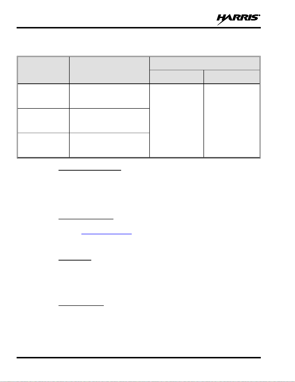
Table 1-1 through Table 1-5 list the recommended minimu m safe l ateral dist anc es fo r a
controlled environment and for unaware bystanders in an uncontrolled environment,
from transmitting antennas (i.e., monopoles over a ground plane, or dipoles). Table 1-1
through Table 1-4 specify mini mum distances for the respective VRM S section of the
vehicular repeater on a per antenna basis. Table 1-5 specifies minimum distances for
the VRBS section of the vehicular repeater on a per antenna basis. This data is based
upon the mobile radio installed in a motor vehicle with the radio transmitting at its
uncontrolled r
radio’s transmitting antenna.
6
Page 7
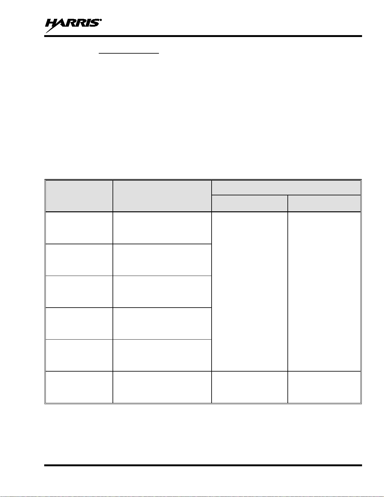
1.3.1 Mobile Antennas
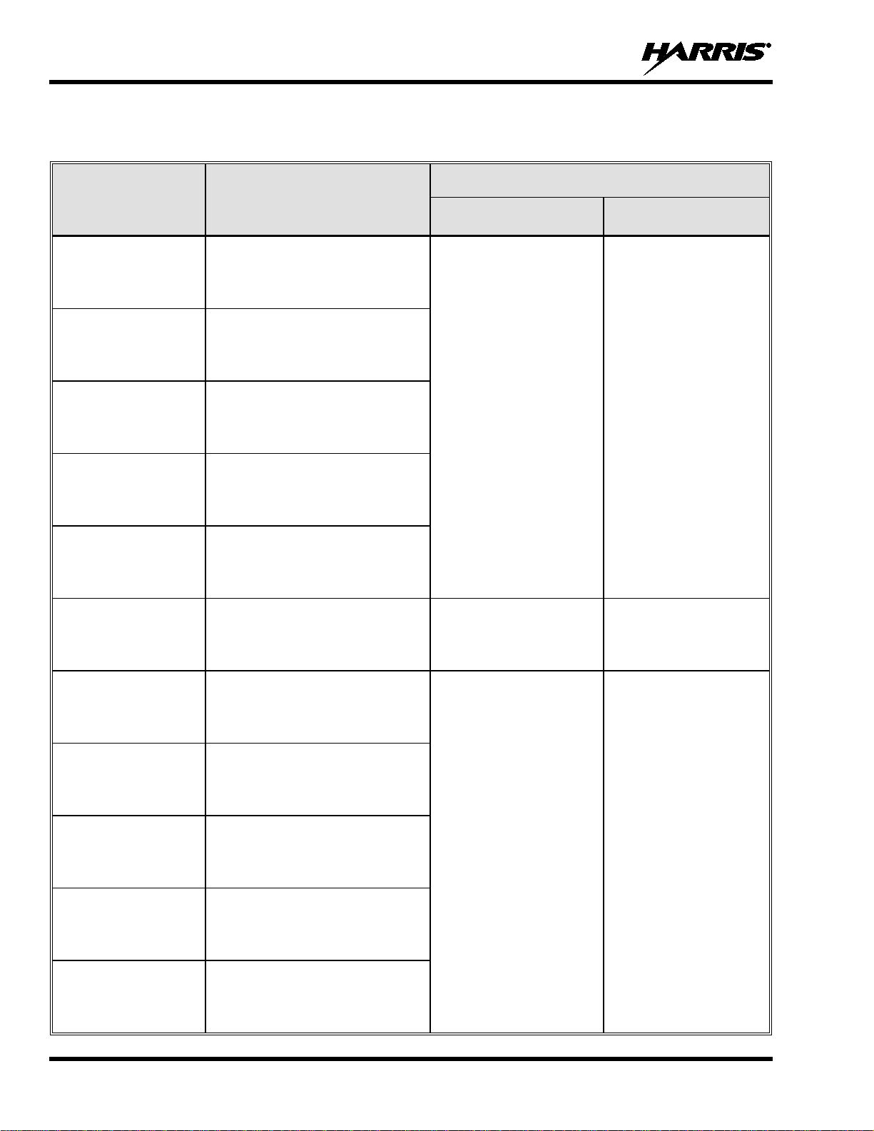
Table 1-1: Recommended Minimum Safe Lateral Distance
DISTANCE FROM TRANSMITTING ANTENNA
CONTROLLED
ENVIRONMENT
UNCONTROLLED
ENVIRONMENT
The antennas for the radio must be installed in accord ance with guidelines and procedures contained in
the Installation and Product Safety Manual. These mobile antenna installation guidelines are limited to
metal body motor vehicles or vehicles with appropriate ground planes. The antenna must be installed in
accordance with:
• The requirements of the antenna manufacturer/supplier included with the antenna.
• Instructions in the Installation and Product Safety Manual, including minimum antenna cable lengths.
The Installation and Product Safety Manual contains specific information on how to install the
antennas to facilitate recommended operating distances to all potentially exposed persons.
Use only the Harris-approved/supplied antenna(s), or an approved replacement antenna. Unauthorized
antennas, modifications, or attachments could damage the radio and may violate FCC regulati ons.
ANTENNA
PART NUMBER
MM-018336-001, Rev. E
from Transmitting Antenna for Mobile Radio-to-Network Radio Link
(VRMS7010/VRMS7020 Transmit/Receive Antenna)
RECOMMENDED MINIMUM LATERAL HUMAN BODY
ANTENNA DESCRIPTION
AN-125001-002
(mount) with
AN-225001-001
(element)
AN-125001-002
(mount) with
AN-225001-002
(element)
AN-125001-002
(mount) with
AN-225001-003
(element)
AN-125001-002
(mount) with
AN-225001-004
(element)
AN-125001-002
(mount) with
AN-225006-001
(element)
AN-125001-002
(mount) with
AN-225001-005
(element)
700/800 MHz Standard
Rooftop-Mount;
3 dBd Gain
700/800 MHz Standard
Rooftop-Mount;
Elevated-Feed 3 dBd Gain
700/800 MHz Standard
Rooftop-Mount;
Elevated-Feed, No Ground Plane
3 dBd Gain
700/800 MHz Standard
Rooftop-Mount;
Low-Profile 2 dBd Gain
132 to 960 MHz, ¼-Wavelength;
Standard Rooftop-Mount;
0 dBd Gain; Field-Tuned
700/800 MHz Standard
Rooftop-Mount;
5 dBd Gain
9.8 Inches
(25 Centimeters)
11.8 Inches
(30 Centimeters)
21.7 Inches
(55 Centimeters)
23.6 Inches
(60 Centimeters)
7
Page 8
MM-018336-001, Rev. E
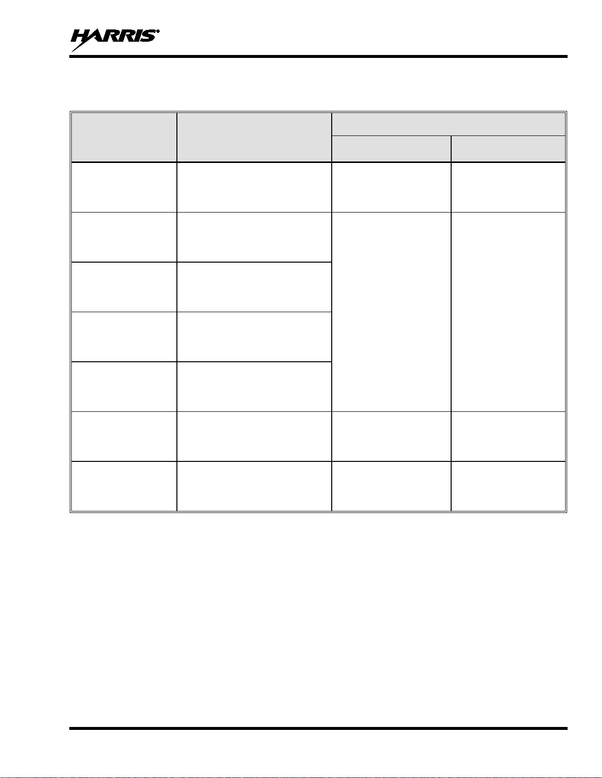
Table 1-1: Recommended Minimum Safe Lateral Distance
RECOMMENDED MINIMUM LATERAL HUMAN BODY
DISTANCE FROM TRANSMITTING ANTENNA
CONTROLLED
ENVIRONMENT
UNCONTROLLED
ENVIRONMENT
from Transmitting Antenna for Mobile Radio-to-Network Radio Link
(VRMS7010/VRMS7020 Transmit/Receive Antenna)
ANTENNA
PART NUMBER
AN-125001-004
(mount) with
AN-225001-001
(element)
AN-125001-004
(mount) with
AN-225001-002
(element)
AN-125001-004
(mount) with
AN-225001-003
(element)
AN-125001-004
(mount) with
AN-225001-004
(element)
AN-125001-004
(mount) with
AN-225006-001
(element)
AN-125001-004
(mount) with
AN-225001-005
(element)
AN-125001-006
(mount) with
AN-225001-001
(element)
AN-125001-006
(mount) with
AN-225001-002
(element)
AN-125001-006
(mount) with
AN-225001-003
(element)
AN-125001-006
(mount) with
AN-225001-004
(element)
AN-125001-006
(mount) with
AN-225006-001
(element)
ANTENNA DESCRIPTION
700/800 MHz Thick
Rooftop-Mount;
3 dBd Gain
700/800 MHz Thick
Rooftop-Mount;
Elevated-Feed 3 dBd Gain
700/800 MHz Thick
Rooftop-Mount;
Elevated-Feed, No Ground Plane
3 dBd Gain
700/800 MHz Thick
Rooftop-Mount;
Low-Profile 2 dBd Gain
132 to 960 MHz, ¼-Wavelength;
Thick Rooftop-Mount;
0 dBd Gain; Field-Tuned
700/800 MHz Thick
Rooftop-Mount;
5 dBd Gain
700/800 MHz GPS Combo
Rooftop-Mount;
3 dBd / 5.15 dBi Gain
700/800 MHz GPS Combo
Rooftop-Mount;
Elevated-Feed 3 dBd Gain
700/800 MHz GPS Combo
Rooftop-Mount;
Elevated-Feed, No Ground Plane
3 dBd Gain
700/800 MHz GPS Combo
Rooftop-Mount;
Low-Profile 2 dBd Gain
132 to 960 MHz, ¼-Wavelength;
GPS Combo Rooftop-Mount;
0 dBd Gain; Field-Tuned
9.8 Inches
(25 Centimeters)
11.8 Inches
(30 Centimeters)
9.8 Inches
(25 Centimeters)
21.7 Inches
(55 Centimeters)
23.6 Inches
(60 Centimeters)
21.7 Inches
(55 Centimeters)
8
Page 9
MM-018336-001, Rev. E
Table 1-1: Recommended Minimum Safe Lateral Distance
RECOMMENDED MINIMUM LATERAL HUMAN BODY
DISTANCE FROM TRANSMITTING ANTENNA
CONTROLLED
ENVIRONMENT
UNCONTROLLED
ENVIRONMENT
from Transmitting Antenna for Mobile Radio-to-Network Radio Link
(VRMS7010/VRMS7020 Transmit/Receive Antenna)
ANTENNA
PART NUMBER
AN-125001-006
(mount) with
AN-225001-005
(element)
AN-125001-008
(mount) with
AN-225001-001
(element)
AN-125001-008
(mount) with
AN-225001-002
(element)
AN-125001-008
(mount) with
AN-225001-003
(element)
AN-125001-008
(mount) with
AN-225001-004
(element)
AN-125001-008
(mount) with
AN-225006-001
(element)
AN-125001-008
(mount) with
AN-225001-005
(element)
ANTENNA DESCRIPTION
700/800 MHz GPS Combo
Rooftop-Mount;
5 dBd / 7.15 dBi Gain
700/800 MHz Magnetic-Mount;
3 dBd Gain
700/800 MHz Magnetic-Mount;
Elevated-Feed 3 dBd Gain
700/800 MHz Magnetic-Mount;
Elevated-Feed, No Ground Plane
3 dBd Gain
700/800 MHz Magnetic-Mount;
Low-Profile 2 dBd Gain
132 to 960 MHz, ¼-Wavelength;
Standard Rooftop-Mount;
0 dBd Gain; Field-Tuned
700/800 MHz Magnetic-Mount;
5 dBd Gain
11.8 Inches
(30 Centimeters)
9.8 Inches
(25 Centimeters)
9.8 Inches
(25 Centimeters)
11.8 Inches
(30 Centimeters)
23.6 Inches
(60 Centimeters)
21.7 Inches
(55 Centimeters)
21.7 Inches
(55 Centimeters)
23.6 Inches
(60 Centimeters)
9
Page 10
MM-018336-001, Rev. E
CONTROLLED
ENVIRONMENT
UNCONTROLLED
ENVIRONMENT
CONTROLLED
ENVIRONMENT
UNCONTROLLED
ENVIRONMENT
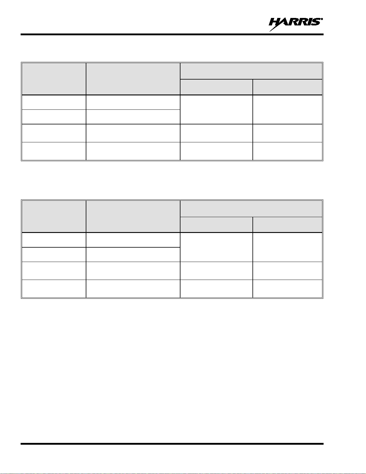
Table 1-2: Recommended Minimum Safe Lateral Distance from Transmitting Antenna for Mobile
Radio-to-Network Radio Link (50-Watt M7300/XG-75M-based VRMS7030 Transmit/Receive Antenna)
ANTENNA
ELEMENT
PART NUMBER
AN-225002-001 136 to 174 MHz, 0 dBd Gain
AN-225006-001 132 to 960 MHz, 0 dBd Gain*
AN-225002-003 136 to 174 MHz, 3 dBd Gain*
AN-225002-004 136 to 174 MHz, 2.4 dBd Gain*
* Element must be tri mmed to proper length in order to minimize antenna system VSWR.
ANTENNA ELEMENT
DESCRIPTION
RECOMMENDED MINIMUM LATERAL HUMAN BODY
DISTANCE FROM TRANSMITTING ANTENNA
24.8 Inches
(63 Centimeters)
35.0 Inches
(89 Centimeters)
32.7 Inches
(83 Centimeters)
55.1 Inches
(140 Centimeters)
78.0 Inches
(198 Centimeters)
72.8 Inches
(185 Centimeters)
Table 1-3: Recommended Minimum Safe Lateral Distance from Transmitting Antenna for Mobile
Radio-to-Network Radio Link (110-Watt M7300/XG-75M-based VRMS7030 Transmit/Receive Antenna)
ANTENNA
ELEMENT
PART NUMBER
AN-225002-001 136 to 174 MHz, 0 dBd Gain
AN-225006-001 132 to 960 MHz, 0 dBd Gain*
ANTENNA ELEMENT
DESCRIPTION
RECOMMENDED MINIMUM LATERAL HUMAN BODY
DISTANCE FROM TRANSMITTING ANTENNA
36.6 Inches
(93 Centimeters)
81.9 Inches
(208 Centimeters)
AN-225002-003 136 to 174 MHz, 3 dBd Gain*
AN-225002-004 136 to 174 MHz, 2.4 dBd Gain*
* Element must be trimmed to proper length in order to minimize antenna system VSW R.
52.0 Inches
(132 Centimeters)
48.4 Inches
(123 Centimeters)
115.7 Inches
(294 Centimeters)
107.9 Inches
(274 Centimeters)
10
Page 11
MM-018336-001, Rev. E
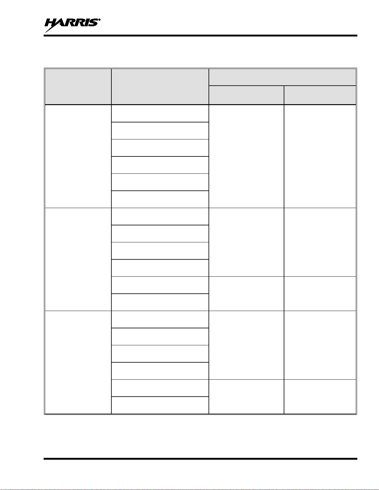
Table 1-4: Recommended Minimum Safe Lateral Distance from Transmitting Antenna for Mobile
Radio-to-Network Radio Link (Multiband Unity XG-100M-based VRS7030 Transmit/Receive Antenna)
RECOMMENDED MINIMUM LATERAL HUMAN BODY
DISTANCE FROM TRANSMITTING ANTENNA
CONTROLLED
ENVIRONMENT
28.3 inches
(72 centimeters)
24.4 inches
(62 centimeters)
33.9 inches
(86 centimeters)
7.9 inches
(20 centimeters)
7.9 inches
(20 centimeters)
UNCONTROLLED
ENVIRONMENT
63.0 inches
(160 centimeters)
54.3 inches
(138 centimeters)
75.6 inches
(192 centimeters)
19.7 inches
(50 centimeters)
24 inches
(61 centimeters)
RF BAND
VHF
UHF
700/800 MHz
ANTENNA
PART NUMBERS
AN-125001-002 (mount) with
12099-0310-01 (element)
AN-125001-004 (mount) with
12099-0310-01 (element)
AN-125001-006 (mount) with
12099-0310-01 (element)
AN-125001-008 (mount) with
12099-0310-01 (element)
AN-125001-002 (mount) with
12099-0330-01 (element)
AN-125001-004 (mount) with
12099-0330-01 (element)
AN-125001-002 (mount) with
12099-0310-01 (element)
AN-125001-004 (mount) with
12099-0310-01 (element)
AN-125001-006 (mount) with
12099-0310-01 (element)
AN-125001-008 (mount) with
12099-0310-01 (element)
AN-125001-002 (mount) with
12099-0330-01 (element)
AN-125001-004 (mount) with
12099-0330-01 (element)
11
Page 12
MM-018336-001, Rev. E
Profile
Profile
Table 1-5: Recommended Minimum Safe Lateral Distance
from Transmitting Antenna for Vehicular Repeater-to-Portable Radio Link
(VRBS7010/VRBS7020/VRBS7030 Transmit/Receive Antenna)
RECOMMENDED MINIMUM LATERAL HUMAN
ANTENNA
PART NUMBER
ANTENNA DESCRIPTION
BODY DISTANCE FROM TRANSMITTING ANTENNA
CONTROLLED
ENVIRONMENT
UNCONTROLLED
ENVIRONMENT
AN-125001-002
(mount) with
AN-225001-004
(element)
AN-125001-004
(mount) with
AN-225001-004
(element)
AN-125001-008
(mount) with
AN-225001-004
(element)
Standard Rooftop-Mount with LowLoss Cable and 700/800 MHz Low-
Profile 2 dBd Gain Element
Thick Rooftop-Mount with Low-Loss
Cable and 700/800 MHz Low-
2 dBd Gain Element
Magnetic-Mount with Low-Loss
Cable and 700/800 MHz Low-
2 dBd Gain Element
7.9 Inches
(20 Centimeters)
7.9 Inches
(20 Centimeters)
1.3.2 Approved Accessories
The radio has been tested and meets FCC RF guidelines when used with accessories supplied or
designated for use with it. Use of other accessories may not ensure compliance with the FCC’s RF
exposure guidelines, and may violate FCC regulations.
For a list of approved accessories refer to the product manuals, the Products and Services Catalog, or
contact Harris Corporation at 1-800-368-3277.
1.3.3 Contact Information
For additional information on exposure requirements or other information, contact Harris Corporation at
1-800-528-7711 or at www.pspc.harris.com.
1.4 RADIO FREQUENCY INTERFERENCE
1.4.1 FCC Part 15
This device complies with Part 15 of the FCC Rules. Operation is subject to the following two conditions:
1. This device may not cause harmful interference, and
2. This device must accept any interference received, including interference that may cause undesired
operation.
1.4.2 Industry Canada
This device complies with Industry Canada license-exempt RSS standard(s). Operation is sub ject to the
following two conditions: (1) this dev ice may not cause interfer ence, and (2) this dev ice must accept any
interference, including interference that may cause undesired operation of the device.
Le présent appareil est conforme aux C NR d'Industri e Canada appli cables aux app areils radio exe mpts de
licence. L'exploitation est autorisée aux deux conditions suivantes : (1) l'appareil ne doit pas produire de
12
Page 13
MM-018336-001, Rev. E
WARNING
brouillage, et (2) l'utilisateur de l'appareil doit accepter tout brouillage radioélectrique subi, même si le
brouillage est susceptible d'en compromettre le fonctionnement.
1.5 OCCUPATIONAL SAFETY GUIDELINES AND SAFETY TRAINING INFORMATION
To ensure bodily exposure to RF electromagnetic energy is within the FCC allowable limits for
occupational use, always adhere to the following basic guidelines:
• The push-to-talk button should only be depressed when intending to send a voice message.
• The radio should only be used for necessary work-related communications.
• The radio should only be used by authorized and trained personnel. It should never be operated by
children.
• Do not attempt any unauthorized modification to the radio. Changes or modifications to the radio may
cause harmful interference and/or cause it to exceed FCC RF exposure limits. Only qualified
personnel should service the radio.
• Always use only Harris-auth orized accessories (antennas, contr ol heads, speakers/mics, etc.). Use of
unauthorized accessories can cause the FCC RF exposure compliance requiremen t s to be exceeded.
The information listed above provides the user with information needed to make him or her aware of a RF
exposure, and what to do to assure that this radio operates within the FCC exposure limits of this radio.
1.6 COMMON HAZARDS
The operator of any mobile radio shou ld be aware of certain hazards common to
the operation of vehicular radio transmissions. Possible hazards include but are
not limited to:
• Explosive Atmospheres — Just as it i s dangero us to fuel a vehicle with its engine i s running, be sure
to turn the radio OFF while fueling the vehicle. If the radio is mounted in the trunk of the vehicle,
DO NOT carry containers of fuel in the trunk.
Areas with potentially explosive atmosphere are o ften, but not alway s, clearly marked. T urn the radio
OFF when in any area with a potentially expl osive atmosphere. It is rare, but not impossible that the
radio or its accessories could generate sparks.
• Interference To Vehicular Elec tronic Systems — Electronic fuel injection systems, electronic anti-
skid braking systems, electronic cruise control systems, etc., are typical of the types of electronic
devices that can malfunction due to the lack of protection from radio frequency (RF) energy present
when transmitting. If the vehicle contai ns such equipment, consult t he dealer for the make of v ehicle
and enlist his aid in determining if such electronic circuits perform normally when the radio is
transmitting.
• Electric Blasting Caps — To prev ent accidental detonation of electric blasting caps, DO NOT use
two-way radios within 1000 feet (305 meters) of blasting operations. Always obey the “Turn Off
Two-Way Radios” (or equivalent) signs posted where electric blasting caps are being used (OSHA
Standard: 1926.900).
• Radio Frequency Energy — To prevent burns or related physical injury from radio frequency
energy, do not operate the transmitter when anyon e outside of the vehicle is wi thin the minimu m safe
distance from the antenna as specified in Table 1-1 and Table 1-5. Refer to Section 1.2 for additional
information.
13
Page 14

MM-018336-001, Rev. E
• Vehicles Powered By Liquefied Petroleum (LP) Gas — Radio installation in vehicles powered by
liquefied petroleum gas, where the LP g as container is located in the trunk or other seal ed-off space
within the interior of the vehicle, must conform to the National Fire Protection Association standard
NFPA 58. This requires:
The space containing the radio equipment must be isolated and sealed from the space containing
the LP gas container and its fittings.
Outside filling connections must be used for the LP gas container.
The LP gas container space shall be vented to the outside of the vehicle.
• Vehicles Equipped with Airbags — For driver and passenger safety, avoid mounting the radio’s
control head (or any other component) above or near airbag deployment areas. In addition to driverside and passenger-side front-impact airbags, some vehicles may also be equipped with side-impact
airbags. For occupant safety, verify the location of all airbags within the vehicle before installing the
radio equipment.
1.7 SAFE DRIVING RECOMMENDATIONS
The American Automobile Association (AAA) advocates the following key safe driving recommendations:
• Read the literature on the safe op er ation of the radio.
• Keep both hands on the steering wheel and the microphone in its hanger whenever the vehicle is i n
motion.
• Place calls only when the vehicle is stopped.
• When talking from a moving vehicle is unavoidable, drive in the slower lane. Keep conversations
brief.
• If a conversation requires taking notes or complex thought, stop the vehicle in a safe place and
continue the call.
• Whenever using a mobile radio, exercise caution.
1.8 OPERATING RULES REGULATIONS
Two-way radio systems must be operated in accordance with the rules and regulations of the local,
regional, or national government.
In the United States, the P25 Vehicular Repeater System must be operated in accordance with the rules
and regulations of the Federal Communications Commission (FCC). Operators of two-way radio
equipment, must be thoroughly familiar with the rules that apply to the particular type of radio operation.
Following these rules helps eliminate confusion, assures the most efficient use of the existing radio
channels, and results in a smoothly functioning radio network.
When using a two-way radio, remember these rules:
• It is a violation of FCC rules to interrupt any distress or emergency message. The radio operates in
much the same way as a telephone “party line.” Therefor e, always listen to make sure the channel is
clear before transmitting. Emergency calls have priority over all other messages. If someone is
sending an emergency message – such as reporting a fire or asking for help in an accident, do not
transmit unless assistance can be offered.
14
• The use of profane or obscene language is prohibited by Federal law.
Page 15
MM-018336-001, Rev. E
CAUTION
NOTE
• It is against the law to send false call letters or false distress or emergency messages. The FCC
requires keeping conversations brief and confined to business. Use coded messages whenever
possible to save on-the-air time.
• Using the radio to send personal messages (excep t in an emergency ) is a violation o f FCC rules. Send
only essential messages.
• It is against Federal law to repeat or otherwise make known anything overheard on the radio.
Conversations between others sharing the channel must be regarded as confidential.
• The FCC requires self-identification at certain specific times by means of call letters. Refer to the
rules that apply to the particular type of operation for the proper procedure.
• No changes or adjustments shall be made to the equipment except by an authorized or certified
electronics technician.
Under U.S. law, operation of an unlicensed radio transmitter within the jurisdiction of
the United States may be punishable by a fine of up to $10,000, imprisonment for up to
two (2) years, or both.
1.9 OPERATING TIPS
The following conditions tend to reduce the effective range of two-way radios and should be avoided
whenever possible:
• Operating the radio in areas of low terrain, or while under power lines or bridges.
• Obstructions such as mountains and buildings.
In areas where transmission or reception is poor, communication improvement may
sometimes be obtained by moving a few yards in another direction, or moving to a
higher elevation.
15
Page 16

MM-018336-001, Rev. E
NOTE
NOTE
support vehicular repeater operations on P25 conventional
Incident vehicular repeater mode is only available in
NOTE
when it is operating as a
2 INTRODUCTION
2.1 GENERAL INFORMATION
The VRS7000 series of Project 2 5 (P25) vehicu lar repeaters includes the three (3) distinctly different P25
Vehicular Repeater Systems: the VRS7010, the VRS7020, and the VRS7030. Additionally, the VRS7030
vehicular repeater has three sub-types based upon the mobile radio which it is equipped with. Unless
otherwise stated, operating procedures presented in this manual apply to all in the series. Each repeater
has different radio frequency bands upon which it operates on. The bands are presented in Figure 2-1 on
page 17 and in
The VRS7000 vehicular repeater has three (3) primary operating modes. First, it can function as a
standard mobile radio for P25 trunked and P25 conventional radio networks. This mode of operation is
called the “mobile radio mode.” In the mobile radio mode, the vehicular repeater section of the VRS7000
is essentially disabled. Second, the VRS7000 can function as a vehicular repeater in a P25 conventional or
a P25 trunked radio network. This mode of operation is called the “Extended Coverage vehicular repeater
mode” or “extended coverage mode” or simply “XCOV” for short. Third, it can function as an
independent off-the-network P25 base station where other radios can connect to it. This vehicular repeater
mode of operation is called the “Scene-Of-Incident mode” or simply “SOI” for short.
Figure 2-2 on page 19.
From this point forward, any reference of “VRS7000” in this manual applies to all P2 5
vehicular repeater systems, unless ot herwise stated.
The VRS7000 cannot operate as a vehicular repeater wh en it is operating as a mobile radio (i.e., in the
mobile radio mode). Likewise, it cannot operate as a mobile radio when it is operating as a vehicular
repeater.
Vehicular repeater mode operation s on a P25 conventional net work require XGP rad io
firmware. Refer to the respective NOTE on page 17 for additional information. ECP
radio firmware does not
networks. Also, the Scene-OfXGP radio firmware. Consult with your radio sy stem’s network administration personnel for additional information.
As of the publication of this manual, only Harris-made P25 trunked radios can connect
to (i.e., be “clients” of) a VRS7000 vehicular repeater
vehicular repeater.
The VRS7000 consists of two (2) mobile radio systems coupled together with specialized interface
hardware. As illustrated in Figure 2-1 on page 17, its Vehicular Repeater Mobile System (VRMS)
provides the radio frequency (RF) link to the radio network, and the Vehicular Repeater Base System
(VRBS) provides the RF link for nearby P25 radios. A control head, microphone speaker, and two (2)
antennas complete the radio installation.
2.2 PRIMARY OPERATING MODES
16
2.2.1 Mobile Radio Mode (Vehicular Repeater Disabled)
The VRS7000 operates like a normal mobile radi o when its vehicular repeater mod e is disabled. When in
the mobile radio mode, the VRS7000 operates on and provides communications via a P25 trunked, a P25
conventional, or an analog conventional radio network. The type of radio network is determined by the
Page 17

MM-018336-001, Rev. E
NOTE
) for information about the Operator’s
NOTE
. Consult with your radio system’s
P25 Vehicular Repeater System
Nearby Harris
P25 Radios
(e.g., P7200 and
P7300 Portable
Radios)
P25 Radio Network RF Link
VRBS
(VRBS7010: 700 MHz)
(
VRBS7020: 800 MHz)
(VRBS7030: 700/800 MHz)
Client Radio-to-Vehicular Repeater
RF Links
Vehicle-Mounted
Antenna
Vehicle-Mounted
Antenna
VRMS
(VRMS7010: 800 MHz)
(VRMS7020: 700 MHz)
(VRMS7030: VHF)
P25 Base
Station
Speaker
Microphone
P25
Client
Radio
P25
Client
Radio
P25
Client
Radio
Control Head
(CH-721 System Model shown)
Figure 2-1: Operational Diagram of Extended Coverage (XCOV) Vehicular Repeater Mode
“system” selected by the radio op erator. Radio control and voice communications are accomplished via
the radio’s control head, the “push-to-talk” (PTT) type microphone, and the speaker connected to the
control head. Using the control head, microphone and speaker, the radio user/operator can control the
radio and communicate with other radio users and console dispatchers in the radio network.
In this mode, nearby radio users can only communicate with the VRS7000 radio user/operator if they can
also directly access the same radio network and/or radio channels/frequencies. Since the vehicular
repeater functionality of the VRS7000 is completely disabled in the mobile radio mode, nearby radios
cannot link through the VRS7000 to the radio network.
Refer to Section 5 of this manual (page 38
Manuals that describe using the VRS7000 in the mobile radio mode.
2.2.2 Extended Coverage (XCOV) Vehicular Repeater Mode
When the VRS7000 is operating in the extended coverage vehicular repeater mode, it provides the
network extension that enables nearby P25 radios operating on a vehicular repeater radio frequency
channel to access a P25 radio network. This mode of operation is sometimes abbreviated “vehicular
repeater mode” or simply “XCOV mode.” As illustrated in Figure 2-1, portable radio coverage is
extended due to the VRS7000’s high-performance mobile antenna system and higher transmitter output
power used to access the P25 radio network. In this mode, the VRS7000 can significantly enhance inbuilding penetration for P25 portable radios that can operate on the same radio frequency band as the
vehicular repeater. Typical operational scenarios include in-building tactical operations, joint training
exercises, and search-and-rescue operations in remote (i.e., RF-fringe-area) areas.
The XCOV vehicular repeater mode can only function when the VRS7000 is operating
on a P25 trunked radio network if the VRS7000 has XGP Release R1A radio firmware
or ECP Release R11A (or later) radio firmware
network administration personnel for details.
The XCOV vehicular repeater mode can fun ction when the VRS7000 is operating on
either a P25 trunked or a P25 conventional radio network if the VRS7000 has XGP
Release R2A (or later) radio firmware.
17
Page 18

MM-018336-001, Rev. E
When a nearby P25 radio is communicating through the VRS7000, it is considered “connected” to or a
“client” on the VRS7000. The VRS7000 cannot function as a standard/normal mobile radio when it is
operating in the XCOV vehicular repeater mode. Instructions on enabling and disabling this VRS7000
mode are included in Section 4 of this manual.
P25 radio users connect to a VRS7000 by manually making a “system” (aka., “zone”) change at the radio
to connect to an active VRS7000 vehicular repeater. After selecting a zone/system allocated for VRS7000
vehicular repeater operation, the radio then scans for an active vehicular repeater channel. Vehicular
repeater channels are pre-programmed into each P25 radio requiring operation on a VRS7000. For P25
trunked networks, a P25 radio can only connect to a VRS7000 if the radio is registered for
communications on the respective P25 trunked radio network.
After a P25 radio initially connects t o a VRS7000, “REGISTER” briefly appears in the radio’s display.
This indicates the radio is registered on th e P25 radio network via the VRS7000. Therefore, the radio can
be used to communicate with other radio users on the radio network and with radios connected to the
VRS7000.
The VRS7000 operator can place the VRS7000 into the XCOV vehicular repeater mode via a menu
selection or preset button press at the radio’s control head. Likewise, the operator can disable this mode
via a control head menu selection or preset butto n press. Alternately, the VRS7000 radio installation may
be wired so this mode can be enabled and disabled by an exter nal switch located on the vehicle’s dash
panel, console panel, or elsewhere.
When the VRS7000 is operating in the XCOV vehicular rep eat er mode, it fun ction s lik e a Voi ce and Dat a
Over Control (VDOC) site for the nearby P25 rad ios co nnected to it. Essentially, the P25 client radios and
the VRBS7000 are linked together via P25 VDOC protocols on the VRBS7000’s VDOC RF ch annel. If
properly programmed, both P25 portable and P25 mobile radios can connect to the VRS7000 when it is
operating in the XCOV vehicular repeater mode.
For the XCOV vehicular repeater mode, P25 radios operating through the VRS7000 (i.e., “P25 client
radios”) maintain the following funct ions across the two RF links:
• P25 Group Call — P25 radios connected to the VRS7000 can communicate on a common talk
group, or on multiple different talk groups. When it is operating in the XCOV vehicular repeater
mode, the VRS7000 provides up to sixty-four (64) talk groups (i.e., a different talk group selected at
each radio). Digital clear voice and digital encrypted voice group calls are supported.
• P25 Individual Call — Unit-to-unit calls between two P25 client radios and between a P25 client
radio and a radio/console on the P25 radio network are supported. Digital clear voice and digital
encrypted voice individual calls are supported.
• P25 User ID — Caller identification information is sent between a P25 client radio and the P25radio
network.
• P25 Emergency — The link through the VRS7000 provides P25 emergency communications
between the P25 client radios and the P25radio network.
• P25 System All Call (from Network Only) — A system-wide all-call transmission from the P25
radio network is forwarded to P25 client radios.
18
• Call Grant and Call Queued Tones — A P25 client radio gen erates call grant an d call queued tones
in a similar manner as if it is operating directly on the P25 radio network.
• Request Status Message (RSM) — An RSM messa ge can be sent from a P25 clien t radio connected
to a VRS7000 operating in XCOV mode to dispatch consoles in the P25 radio network. This feature
is available in radio firmware XGP Release R1 A and later.
Page 19

MM-018336-001, Rev. E
P25 Vehicular Repeater System
Nearby Harris
P25 Radios
VRBS
(VRBS7010: 700 MHz)
(VRBS7020: 800 MHz)
(VRBS7030: 700/800 MHz)
Client Radio-to-Vehicular Repeater
RF Links
Vehicle-Mounted
Antenna
Vehicle-Mounted
Antenna (Not Used
in This Mode)
VRMS
(VRMS7010: 800 MHz)
(VRMS7020: 700 MHz)
(VRMS7030: VHF)
Control Head
(CH-721 System Model shown)
Speaker
Microphone
P25
Client
Radio
P25
Client
Radio
P25
Client
Radio
P25
Client
Radio
P25
Client
Radio
Figure 2-2: Operational Diagram of Scene-Of-Incident (SOI) Vehicular Repeater Mode
• Status Updates — Real-time status update messages can be sent from a P25 client radio connected to
a VRS7000 operating in XCOV mode to the P25 radio network.
• Request-To-Talk (RTT) and Emergency Request-To-Talk (ERTT) — An RTT/ERTT message
can be sent from a P25 client radio through the VRS7000 to dispatch consoles in the P25 radio
network. This feature is availab le in radio firmware XGP Release R1A and later, and radio firmware
ECP Release R15A and later.
Up to sixty-four (64) P25 radios can connect to a V RS7000 when it is in XCOV mode. These radio users
can communicate via the same talk group or via multiple different talk groups. Although up to sixty-four
(64) talk groups can be used by connected radios (i.e., a different talk group selected at each radio),
excessive call queuing can result when multiple talk groups and/or individual calls are utilized by the P25
client radios. Refer to Section 2.4.5 on page 22 for additional information.
When operating in the extended coverage (XCOV) v ehicular repeater mode, calls transmitted from the
P25 client radios are not routed to the VRS7000’s speaker. Refer to Section 2.4.3 on page 21 for
additional information.
The VRS7000 supports end -to-end Advanced Encryption Standard (AES) encrypted calls. If a P25 client
radio is transmitting an encrypted call, the VRS7000 si mply repeats th e call to t he netwo rk base stat ion. It
does not un-encrypt and then re-encrypt the call.
2.2.3 Scene-Of-Incident (SOI) Vehicular Repeater Mode
The Scene-Of-Incident (SOI) vehicu lar repeat er mod e enables nearby P25 radios operating on a vehicular
repeater radio frequency channel the ability to commun icate with each o ther usi ng the VRS7000 as a base
station. This mode is advantageous for use during any operational scenario where network communications (including communications with console dispatchers) is not required and/or not possible. It does not
provide access to any P25 radio network, trunked or conventional. An operational d iagram is shown in
Figure 2-2.
19
Page 20

MM-018336-001, Rev. E
CAUTION
The VRS7000 vehicular repeater has only one (1) talk path. Therefore, it is
NOTE
P25 radios operating on the VRS7000 (i.e., “P25 client radios”) via SOI vehicular repeater mode maintain
the following basic radio communication functions:
• P25 Group Call — P25 radios connected to the VRS7000 can communicate on a common talk
group, or on multiple different talk groups. Up to sixty-four (64) talk groups are supported (i.e., each
radio can have a different talk group selected). Digital clear voice and dig ital encrypted voice group
calls are supported.
• P25 Individual Call — The SOI mode supports unit-to-unit calls between two P25 client radios.
Digital clear voice and digital encrypted voice individual calls are supported.
• P25 Emergency — The link through the VRS7000 provides P25 emergency communications
between the P25 client radios.
• Call Grant and Call Queued Tones — A P25 client rad io generates call grant and call queued to nes
in a similar manner as if it is operating directly on the P25 radio network.
Like the XCOV mode described in the previous section, the SOI vehicular repeater mode allows up to
sixty-four (64) P25 radios to connect to a VRS7000, and these radio users can communicate via the same
talk group or via multiple different talk groups. Although up to sixty-four (64) talk groups can be used by
connected radios in this mode (i.e., a different talk group selected at each ra dio), excessive call queuing
can result when multiple talk groups and/or individual calls are utilized by the P25 client radios.
recommended that all radio users operate on t he same talk g roup. Refer to Section
2.4.5 on page 22 for additional information.
When operating in the SOI vehicular repeat er mode, calls transmitted from the P25 clien t radios are not
routed to the VRS7000’s speaker. Refer to Section 2.4.3 on page 21 for additional information.
The VRS7000’s SOI mode supports end-to-end Advanced En cryption Standard (AES) encrypted call s. If
a P25 client radio is transmitting an encrypted call, the VRS7000 simply repeats the call to the other
radio(s). The VRS7000 does not un-encrypt and then re-encrypt the call.
2.3 MULTIPLE ON-SCENE VEHICULAR REPEATERS
The VRS7000 P25 Vehicular Repeater System desig n supports multiple on-scene VRS 7000s via multiple
radio frequency channels assigned for system-wide vehicular repeater use. When a vehicular repeater
mode is enabled at a particu lar VRS7000, t he VRS7000 automatically selects an unused pre-programmed
channel allocated for vehicular repeater operations after a scanning algorithm determines the channel is
available.
Vehicles equipped with a VRS7000 must maintain an antenn a separation distan ce of at
least ten (10) feet during vehicular repeater operations.
When multiple VRS7000s are on a scene, a P25 radio user must manually make a “system” (aka., “zo ne”)
change to connect to a VRS7000. Subsequently, the P25 radio will scan for and, if properly registered,
connect to an available VRS7000 operating in a vehicular repeater mode. For P25 trunked networks, a
P25 radio can only connect to a VRS7000 if the VRS7000 is registered for communications on the
respective P25 trunked radio network.
VRS7000s in the network can be configured so when a VRS7000 leaves a scene, P25 client radios
connected to it will automatically transition to a second on-scene VRS7000. This automatic hand-off
operation requires proper vehicular repeater channel/frequency configuration in all VRS7000s and P25
20
Page 21

MM-018336-001, Rev. E
NOTE
client radios. During the transition, each P25 client radio displ ays “CC SCAN” while it is searching for
another on-scene VRS7000.
2.4 LIMITATIONS OF THE VRS7000 VEHICULAR REPEATER
2.4.1 General Information
The VRS7000 P25 Vehicular Repeater System provides unique system advantages by extending network
coverage to nearby P25 radios operating in otherwise poor radio frequency coverage areas of the P25
radio network. It can significantly improve radio communications for P25 portable radio users operating
in buildings or in other in-network weak-signal areas where portable radio communications is otherwise
problematic or not possible. However, the VRS7000 presents certain communication limitations as
described in this section.
All users must be properly trai ned on correct vehicular repeater oper ating procedures.
This training should include but not be limited to familiarity with VRS7000
limitations, as described in the following subsections.
2.4.2 Limited Feature Set
When it is operating as a vehicular repeater, the VRS7000 cannot provide all the communication features
normally provided by a direct radio link to a P25 radio network. The VRS7000 is not intended to replace
the functionality of the P25 radio network’s fixed RF base station/site equipment. The VRS7000’s limited
feature set for vehicular repeater operations is listed in Section 2.2.2 of this manual.
2.4.3 Vehicular Repeater Mode Disables Mobile Radio Mode
The VRS7000 P25 Vehicular Repeater System cannot function as a normal mobile radio when it is
operating as a vehicular repeater. The speaker and microph one connected to the control head are disabled
when the VRS7000 is operating as a vehicular rep eater. Also, the control head does not indicate networkonly calls to the VRS7000, and other functions such as talk group scanning, are not possible. When the
VRS7000 is operating as a vehicular repeater, the control head primarily indicates vehicular repeater
mode-related operations.
2.4.4 Loss of P25 Trunked Network Connectivity Disconnects Client Radios
Connected via XCOV Mode
If a VRS7000 P25 Vehicular Repeater Sy stem operating on a P25 trunked radio network loses contact
with the network that it is currently logged into, it automatically scans for another control channel to
maintain network connectivity. During this time, a “CC SCAN” ind ication appears in the control head’s
display to indicate the VRS7000 is scanning/searching for a network control channel. Also, if alert tones
are programmed on, an alert tone sounds in the speaker when the control channel scan begins. Note that a
control channel scan can occur both when the vehicular repeater is operational/enabled (i.e., the VRS7000
is in the XCOV vehicular repeater mode), and when the vehicular repeater is not operational (i.e., the
VRS7000 is in the mobile radio mode).
If the VRS7000 loses network connectivity for several seconds when the vehicular repeater is
operational/enabled (i.e., as indicated by “CC SCAN” in the control head’s display), it automatically
disconnects all connected P25 radio clients and disables the XCO V vehicular repeater mode. In this case,
all P25 radios that were connected to the VRS7000 will themselves indicate the loss of connecti vity with
the VRS7000 by also indicating control channel scan (“CC SCAN”), and by sounding an alert tone if
programmed to do so. After disconnecting, each P25 radio will automatically scan for another VRS7000
operating as a vehicular repeater. If anoth er VRS7000 is found, the P25 radio will attempt to connect to
21
Page 22

MM-018336-001, Rev. E
NOTE
hen arriving at a
CAUTION
that VRS7000. If connection is successful, communications through that VRS7000 can continue. If
connection is not successful after a sho rt p erio d of time and radio communications must continue, the P25
radio user must manually make a “system” (aka., “zone”) change to another available radio
system/network, or select and use a pre-programmed talk-around channel.
For P25 radio network communications (trunked or conventional), w
scene, a vehicle with the VRS7000 must be located/positioned so it has a reliable RF link
to the P25 radio system. If a reliable RF link canno t be established, reposition the vehicle
to another location, such as on the opposite side of the building, to reduce or eliminate
“CC SCAN” indications before enabling the XCOV vehicular repeater mode.
If a reliable RF link cannot be achieved in the mobile radio mode, do not enable/activate
the XCOV vehicular repeater mode. For a P25 trunked radio network, using the XCOV
vehicular repeater mode is not reco mmended if, while in mobile radio mode, “CC SCAN”
is indicated more than once approximately every thirty (30) seconds.
2.4.5 One Talk Path
The VRS7000 P25 Vehicular Repeater System prov ides o nly on e talk path for all P25 radios connected to
it. From the vehicular repeater standpoint, this is a single-channel full-duplex talk path to and from
connected/client P25 radios. Since there is only one talk path, significant call queuing can occur when
multiple P25 radios are attached to the VRS7000. To minimize call queuing, P25 client radio users
should minimize the total number of selected talk groups, and minimize individual call operations.
When P25 client radios are using more than one talk group and/or making
individual call(s), both calls originated from the P25 client radios to the network
and calls originated from the P25radio network to the P25 client radios can be
queued. All radio users and console dispatchers must be aware of this fact when a
VRS7000 is in operation. When critical communications must be accomplished
through the VRS7000, it is recommended that all P25 client radio users utilize only
one (1) common talk group, and not make any individual calls.
2.4.6 Slight Audio Delay Between Client Radios and Network
2.4.6.1 During XCOV Mode
Because of the extra signal processin g performed within th e VRS7000 to ro ute calls when i t is in XCOV
mode, call audio between a P25 radio con nected to the VRS7000 and the P25radio network is delayed by
approximately one-quarter (¼) of a second. This time delay can be heard by simultaneously monitoring a
talk group’s call audio in the speakers of both a P25 radio connected to the VRS7000 and a P25 radio
logged directly onto the respective P25radio network.
2.4.6.2 During SOI Mode
When the VRS7000 is operating in SOI mode, calls between the connected P25 (i.e, client) radios do not
have to pass to radio network. As a result, there is no significant delay in the call audio between the
connected P25 radios.
22
Page 23

MM-018336-001, Rev. E
2.4.7 Other Limitations
The VRS7000 P25 Vehicular Repeater System does not support the following features/functions when it
is operating as a vehicular repeater:
• Patched Talk Groups — When a talk group used by P25 radios connected to the VRS7000 is within a
patch (patches are created by di spatch personnel), call audio on other groups within the patch is not
routed to the P25 radios connected to a VRS7000. Also, call audio from a conn ected P25 radio on a
particular talk group within the patch is not routed to other groups within the patch.
• Simulselected Talk Groups — When a talk group used by P25 radios connected to the VRS7000 is
within simulselect (simulselects are created by dispatch personnel), call audio on other groups within
the simulselect is not routed to the P25 radios connected to a VRS7000.
• Interconnect (PSTN) Calls — Telephone interconnect calls can not be placed by or received by a P25
radio connected to a VRS7000.
• Data Calls — Certain data calls, such as mobile data calls, cannot be sent to or received by a P25
radio connected to a VRS7000.
• RTT/ERTT Messages — RTT and ERTT messages fr om P25 clien t radios can cause v oice calls to be
either queued or completely ignored (i.e., not repeated) by the VRS7000. Voice calls from connected
P25 client radios may be queued if a RTT/ERTT message i s being processed by the VRS7000. Also,
normal voice calls from the network may be ignored while the VRS7000 is processing a RTT/ERTT
message. In these two cases, pr ocessing inclu des the period of time in which the VRS7000 is waiting
on an acknowledgement response from the network. All-calls from the network are not ignored by the
VRS7000; however, an all-cal l received just after a RTT/ERTT message will cause the RTT/ERTT
message to be ignored by the VRS7000.
• Message Trunked Calls — Message trunked calls cannot be sent to or received from a P25 radio
connected to a VRS7000. Repeater channel “hang times” associa ted with messaged trunked group
calls, emergency calls, and individual calls are not supported.
• Dynamic Regroup — Talk groups used by P25 radios connected to a VRS7000 cannot be
dynamically regrouped.
• Roaming — P25 radios connect ed to a VRS7000 cannot automatically roam to another zone/system.
The radio operator must manually make a zone/system change to access another radi o zone/system.
• Console Preempt when a P25 Client Radio is Keyed — A dispatcher cannot preempt a P25 radio
connected to a VRS7000 while the radio is transmitting on a talk group.
• Motorola-Style Emergency Calls — The VRS7000 does not support Motorola-style emergency calls
when it is operating in the XCOV vehicular repeater mode.
• Confirmed Unit-to-Unit Call — Unit-to-unit individual calls (“I-calls”) are not confirmed for P25
radios connected to the VRS7000.
• Acknowledged Unit-to-Unit Call — The acknowledged u nit-to-unit individual (“I-call”) call feature
is not provided to P25 radios connected to the VRS7000.
• Talk Group Priorities — Talk groups used by P25 radios connected to the VRS7000 do not have talk
group priorities.
• Individual Call (I-Call) Block — Individual calls to and from P25 radios connected to the VRS7000
cannot be blocked.
• Subscriber Administration Rights — The VRS7000 does not support subscriber administration rights.
• Invalidated Talk Group Emergency — The VRS7000 does not support the invalid talk group
emergency feature.
• Mobile Radio Steering/Preempt — The VRS7000 does not support the mobile radio steering/preempt
feature.
23
Page 24

MM-018336-001, Rev. E
• Global Positioning System (GPS) — GPS location request and report messages are not routed
through the VRS7000.
• Cross-Band Vehicular Repeater Operation of VRS7010 — With the VRS7010 P25 veh icular repeater
system, client P25 radios connect to the VRS7010 via the 700 MHz radio frequency band, and the
network link is on the 800 MHz band.
• Cross-Band Vehicular Repeater Operatio n of VRS7020 — With the VRS7020 P25 vehicular repeat er
system, client P25 radios connect to the VRS7020 via the 800 MHz radio frequency band, and the
network link is on the 700 MHz band.
• Cross-Band Vehicular Repeater Operation of VRS7030 — With the VRS7030 vehicular repeater
system, client P25 radios connect to the VRS7030 via either the 700 MHz or the 800 MHz radio
frequency band, and the network link is on the VHF radio frequency band (136 to 174 MHz).
2.5 CONTROL HEADS
The VRS7000 vehicular repeater installation includes a control head with a microphone and a speaker.
This equipment provides the interface for the radio’s operator/user.
A VRS7010/VRS7020/VRS7030 vehicular repeater with an XG-75M or an M7300 mobile radio employs
the CH-721 System model control head.
A VRS7030 vehicular repeater with the Unity XG-100M mobile can employ either the CH-100
touchscreen control head or the CH-721 System model head.
2.5.1 CH-100 Control Head
The CH-100 control head features a 4.3-inch high-contrast sunlight-readable touchscreen LCD color
display, providing an easy-to-use menu-driven operator interface. This head also features a Bluetooth
wireless interface for connection of optional equipment such as a wireless speaker/microphone. The
Bluetooth interface also supports radio and control head programming via a wireless connection. The
CH-100 head features an easy-to-use on/off/volume control and group/channel selection controls, an
emergency button, a home button, a USB programming port, a transmit/receive busy indicator, and a
microphone connector.
The CH-100 is shown in Figure 3-1 on page 25. Connectors located on the rear pan el inclu de a DC po wer
connector, two (2) CAN port connectors used for CAN link interconnections, an external speaker
connector, a 9-pin serial port connector for connecting optional equipment such as a mobile data terminal,
and a 25-pin multi-function accessory connector.
®
2.5.2 CH-721 System Model Control Head
The VRS7000 employ s the CH-721 System model control head. Shown in Figure 4-1 on page 32, this
control head provides the user/operator interface for the VRS7000. Th e CH-721 System model control
head has a large easy-to-read 3-line graphical vacuum-fluorescent type display, an on/off/volume control
knob, menu controls, an emergency/home button, a scan on/off button, and three (3) preset buttons. It also
features a 12-key numeric keypad that provides Dual-Tone Multi-Frequency (DTMF) keypad functionality and easier operator system/group selection , three (3) preset buttons, and an emergency/home button.
Other control head components include a microphone connector and two (2) Light-Emitting Diode (LED)
type indictors. One LED indicator is the busy indicator that lights when the VRS7000 is receiving a call.
The other is the transmitter-enabled indicator that lights when it is transmitting. The control head’s
buttons and keys are backlit for nighttime operation.
24
Page 25

MM-018336-001, Rev. E
NOTE
NOTE
CAUTION
NOTE
hen arriving at a
On/Off/Volume
Control
System/Group/-
Channel Selection
Control
Ambient Light
Level Sensor
4.3-Inch LCD Touchscreen Color Display
Emergency Button
Home Button
USB Programming
Port
Microphone
Connector
Built-In
Microphone for
-
Suppression
Main Menu
(soft button)
3 VEHICULAR REPEATER OPERATION WITH
CH-100 CONTROL HEAD
3.1 TURNING ON THE VRS7000
To turn on the VRS7000, rotate the control head’s On/Off/Volume Control knob clockwise out of the
detent position. See Figure 3-1 below. This action powers-up the VRS7000 and the control head. If
enabled through programming, a short beep sounds in the speaker to indicate the radio is ready for
operation. The control head powers-up to its main display.
At power-up, the VRS7000 begins operating in the mobile radio mode. For
additional information about this mode, refer to Section 5. To enable/activate the
vehicular repeater mode, refer to Section 3.2 that follows.
Noise
Figure 3-1: CH-100 Control Head
The VRS7000 should be powered-up for at least ten (10) seconds before enabling a
vehicular repeater mode.
When a vehicular repeater mode is enabled/active, normal mobile radio communications are
not possible with the VRS7000. In other words, the speaker and microphone connected to the
control head do not f unct ion when a ve hicular repeater mode is enabled/active.
For P25 radio network communications (trunked or conventional), w
scene, a vehicle with the VRS7000 must be located/positioned so it has a reliable RF link
to the P25 radio system. If a reliable RF link canno t be established, reposition the vehicle
to another location, such as on the opposite side of the building, to reduce or eliminate
“CC SCAN” indications before enabling the XCOV vehicular repeater mode.
If a reliable RF link cannot be achieved in the mobile radio mode, do not enable/activate
the XCOV vehicular repeater mode. For a P25 trunked radio network, using the XCOV
vehicular repeater mode is not reco mmended if, while in mobile radio mode, “CC SCAN”
is indicated more than once approximately every thirty (30) seconds.
25
Page 26

MM-018336-001, Rev. E
NOTE
If the currently active mission plan has the required
, change the radio’s mission plan to one that
NOTE
to the
will vary from
Consult with your radio system’s network
nistration personnel as necessary, an d obtain the
to access the
the radio’s
These plans are programmed by the
(up) to scroll
in the list
conds
the newly selected
, the radio displays series
e radio
to cancel out of the mission plan change,
CANCEL
3.2 USING A VEHICULAR REPEATER MODE
Follow the procedures in this section to use the XCOV or the SOI vehicular repeater modes.
To use the Scene-Of-Incident (SOI) ve hicular repeater mode, switching to a P25 radio
zone/system is not necessary. For this case, advance to Section 3.2.2 now.
3.2.1 Switch to a P25 Radio Zone/System (Required for XCOV Mode Only)
Before XCOV vehicular repeater mod e can be enabled/activated, the VRS7000 must be operating on a
P25 radio zone/system (either P25 conventional or P25 trunked). Use the following procedure to switch
VRS7000 operation to a P25 radio zone/system:
1.
P25 radio zone/system, advance to step 2 now.
Otherwise
has the required P25 zone/system as follows:
In most cases, a change in the currently active mission plan is not necessary , because it
has the required P25 radio zone/–system. In
the example illustrations at th e left, a change is
made from the “AGENCY-1” plan
“AGENCY-2” plan. Plan names are programmable by the radio system’s network administration personnel; therefore, they
this example.
You cannot make a mission plan change when
the radio is transmitting an emergency.
Currently active
mission plan
(before change).
26
a.
admi
name of the required mission plan.
b. On the CH-100 screen, touch
MAIN MENU
radio’s main menu. See the illustration at the top-left.
c. Touch
PROGRAM to access the list of
mission plans.
radio system’s network administration personnel.
indicates the currently active mission plan .
d. If necessary, u se
(down) and/or
to a page that has the required program’s name.
e. Touch the required plan’s name
(“AGENCY-2” in example at left).
f. Touch
ACTIVATE PLAN a nd th en wait a few s e
for the radio to load and activate
plan. During this activation
of screens indicating its status. When done, th
returns to the main display.
Alternately,
touch
.
Page 27

MM-018336-001, Rev. E
–
-
now.
describes how to
enable and disable a vehicular repeater mode via a
3.2.3
describes how to enable and disable a vehicular
h your radio system’s
network administration personnel as necessary, and
obtain the name of the required zone/system, per
to access the
to access the list
other
(up) to scroll
to a page that has the name of the required
It must be identified with a either the
After a
-
tive newly selected P25 radio network, and begin
NOTE
2. If the currently active zone/–system is the zone/
system required for P25 vehicular repeater opera
tions, advance to Section 3.2.2 or Section 3.2.3
The procedure in Section 3.2.2
control head menu. The procedure in Section
repeater mode via an optional external switch.
Otherwise, change to the required zone/system as follows:
a. If necessary, consult wit
radio programming.
Currently active zone/system
(before change).
In the example illustrations above, a change is made from the “COUNTY-1” P25 trunked
zone/–system to the “COUNTY-2” P25 conventional zone/–system. Names are programmable by the radio system’s network administration personnel, and there–fore will
vary from this example.
b. On the CH-100 screen, touch
MAIN MENU
radio’s main menu. See the illus trat ion at the top- left.
c. From the main menu, touch
ZONES
of zones/systems in the currently active mission plan.
indicates the currently active zone/system
indicates a P 25 trunked zone/system (or an
type of trunked system)
indicates a P25 conventional zone/system
indicates an analog conventional zone/system
d. If necessary, use
(down) and/or
zone/system.
or the .
e. Touch that zone/system name to select it.
short delay, the VRS7000 will switch to the respec
operating on it.
There are two (2) different methods that can be used to enab le and disable a vehicular repeater mode, as
described in the following subsections. The exact method(s) that can be used depends upon radio
programming.
27
Page 28

MM-018336-001, Rev. E
-
radio network, use the
.
The VRS7000 must be operating on a P25 radio
network before XCOV vehicular rep eater mode can be
to access the
VR
i.e., short
to
-
to enable that
NOTE
ming. Consult with your radio
or
nearby P25 radio users with
programmed for P25 vehicular repeater
y
manually making a “system” change to the respective
vehicular repeater channel. If necessary, consult with
-
sor for specific vehicular repeater
tions
for XCOV mode and
To
VRS7000 will return to a normal display, indicating network talk group and/or individual call
information.
For Scene-Of-
ode
For Extended
Coverage
Mode
For XCOV
P25 conventional
zone/system, the
3.2.2 Enable/Disable a Vehicular Repeater Mode via the Control Head’s Menu
To enable a vehicular repeater mode via the CH-100 control head’s menu, follow this procedure. The
radio must be programmed to support this enable/disable method:
1. For XCOV Mode Only: If the VRS7000 is not cur
rently operating on a P25
procedure presented in Section 3.2.1 to switch it to one
enabled/activated.
Incident M
For information
on the Analog VR
see the XG-100M
Operator’s Manual.
2. On the CH-100 screen, touch
MAIN MENU
radio’s main menu. See the illustration at the top-left.
3. On the main menu, touch
VR to access the
(vehicular repeater) menu.
4. On the vehicular repeater menu, touch
XCOV (
for the Extended Coverage vehicular repeater mode)
enable that mode, or SOI (i.e., short for Scene-Of
Incident vehicular repeater mode)
respective mode.
If the XCOV and/or SOI text is grayed-out,
that respective mode is not available p er radio
program
system’s network administration p ersonnel as
necessary.
5. With an indication of STANDBY (illustrated below)
ACTIVE (not illustrated),
radios preoperations can now connect to the VRS7000 b
the radio network administration personnel or a commu
nications supervi
system name(s). Subsequent control head indica
are illustrated in Section 3.2.4
in Section 3.2.5 for SOI mode.
operations on a
T here is
replaced by a C.
disable the vehicular repeater, touch EXIT VR at the top of the display. Upon exiting, the
28
Any connected P25 radio users will be discon nected.
Page 29

MM-018336-001, Rev. E
NOTE
NOTE
the XCOV vehicular repeater mode automatically activates/enables when a portable
onsult with the radio network
3.2.3 Enable/Disable a Vehicular Repeater Mode via External Switch
The VRS7000 with the CH-100 control head may be wired to an external switch used to enable and
disable a vehicular repeater mode. Th e external switch may be located on th e vehicle’s dash panel, on a
console panel near the control head, or elsewhere. Follow this procedure to enable a vehicular repeater
mode via an external switch:
1. For XCOV Mode Only: If the VRS7000 is not currently operating on a P25 radio network, use the
procedure presented in Section 3.2.1 to switch it to one. The VRS7000 must be operating on a P25
radio network before XCOV vehicular repeater mode can be enabled/activated.
2. Place the external switch in the enabled/activated position. When an external switch is used, the
VRS7000 is pre-programming to enter/activate either the XCOV mode or the SOI mode. No user
choice is available.
3. With STANDBY or ACTIVE indicat ed in the control head’s display, nearby P25 radio users with
radios pre-programmed for P25 vehicular repeater operations can now connect to the VRS7000 by
manually making a “system” change to the respective vehicular repeater channel. If necessary,
consult with the radio network administration personnel or a communications supervisor for specific
vehicular repeater system name(s). Subsequent control head indications are illustrated in Section
3.2.4 for XCOV mode and in Section 3.2.5 for SOI mode.
To disable the vehicular repeater mode, place the exte rnal switch in t he disabled/d eactivated posi tion.
The VRS7000 will return to a normal display, indicating network group and/or individual call
information. Any connected P25 radio users will be disconnected.
The VRS7000 can also be configured so the external switch must be activated and a
pre-configured button on the control head must be pressed to enable a vehicular
repeater mode. In this case, to disable the mode, simply press th e same button agai n or
return the switch to the disable position.
Other radio installation options also exist. For example, the VRS7000 can be wired so
radio is removed from an in-vehicle charger. C
administration p ersonnel or a communications supervisor for additional information.
29
Page 30

MM-018336-001, Rev. E
P25T
in XCOV
mode
P25C
is
operating in XCOV mode on a P25 conventional radio system.
STANDBY indicates P25 client radios can connect to the
VRS7000
This is also
indicated via the
at the bottom
of the display.
ACTIV
indicates the
first P25 client radio is attempting to connect.
After the first radio connects, the NUMBER OF VR USERS
indication changes
NOTE:
indication
(where
-
mation purposes only
ber
based upon the registra
sages it
receives from the client radios. It is possible that the displayed
number may be different from the actual num
nected
client radios. For example, if a radio user pulls the battery off
of his/her portable radio without first turning the radio off, the
VRS7000 will not receive a deregistration message from the
radio and the count may be incorrect (i.e., dis
yed number is
1 too high). However, if the radio user later powers-up the
same radio on the same VRS7000, the count can be put back in
sync.
When additional P25 radios connect to the VRS7000, the total
number
is indicated. For example,
NUMBER OF VR USERS:
-
nect
to a
VRS
When a call is made from a P25 client r adio or f rom a radio o n
the network (on a talk group also being used by the P25 client
radios),
E
indication during the call.
When an emergency is declared on a talk group being us e d b y the
P25 client radio(s),
EMERGENCY
also appears when a
its on an emergency
group currently being used by the P25 client radio(s). When a
connected
3.2.4 Indications During XCOV Mode Operations (CH-100 Control Head)
-XCOV indicates the VRS7000 is operating
on a P25 trunked radio system.
-XCOV (not illustrated) indicates the VRS7000
, but none are currently connected.
NUMBER OF VR USERS: 0
E with NUMBER OF VR USERS: 0
from 0 to 1.
The NUMBER OF VR USERS: ##
## is a number between 0 and 64), is for infor
! The VRS7000 updates this num
tion and deregistration mes
ber of con
pla
of connected radios
15 ind icates 15 radios are con
ed. Up to sixty-four (64) P25 radios can connect
7000 when it is in a VR mode.
CALL displays. That indication replaces the ACTIV
EMERGENCY displays.
network radio transm
client radio transm its, CALL appears.
30
Page 31

MM-018336-001, Rev. E
VR
-
Incident mode.
STANDBY indicates P25 client radios can connect to the
VRS7000
This is also
indicated via the
at the bottom
of the display.
ACTIV
indicates the
first P25 client radio is attempting to connect.
After the first radio connects, the NUMBER OF VR USERS
indication changes
NOTE:
indication
(where
-
mation purposes only
ber
based upon the registra
sages it
receives from the client radios. It is possible that the displayed
number may be different from the actual num
nected
client radios. For example, if a radio user pulls the battery off
of his/her portable radio without first turning the radio off, the
VRS7000 will not receive a deregistration message from the
radio and the count may be incorrect (i.e., dis
yed number is
1 too high). However, if the radio user later powers-up the
same radio on the same VRS7000, the count can be put back in
sync.
When additional P25 radios connect to the VRS7000, the total
number
is indicated. For example,
NUMBER OF VR USERS:
-
ed.
7000
when it is in a VR mode.
When a call is made from a P25 cl ient radio,
.
That indication repla
indication during the
call.
When an emergency is declared on a talk group being us e d b y the
P25 client radios,
also
appears when any client radio transmits on an emergency group
currently being us ed by the P25 c lie nt r
3.2.5 Indications During SOI Mode Operations (CH-100 Control Head)
- SOI indicates the VRS70 00 is operating in the Scene-Of
, but none are currently connected.
NUMBER OF VR USERS: 0
E with NUMBER OF VR USERS: 0
from 0 to 1.
The NUMBER OF VR USERS: ##
## is a number between 0 and 64), is for infor
! The VRS7000 updates this num
tion and deregistration mes
ber of con
pla
of connected radios
8 indicates 8 radios are connect
Up to sixty-four (64) P25 radios can connect to a VRS
CALL displays
ces the ACTIVE
EMERGENCY displays. EMERGENCY
adio(s).
31
Page 32

MM-018336-001, Rev. E
NOTE
in the mobile radio mode. For
NOTE
CAUTION
NOTE
hen arriving at a
3-Line Graphical VacuumFluorescent Display
Microphone Connector
Power On/Off/-
Volume
Control Knob
Ramp Control
Emergency/
Home Button
Ramp Control
Transmit (TX)
usy (BSY)
Indicators
Scan On/Off Button
Clear Button
Menu Button
Option Button
System/Group
Knob
Preset Buttons
12-Key DTMF
Keypad
4 VEHICULAR REPEATER OPERATION WITH
CH-721 CONTROL HEAD
4.1 TURNING ON THE VRS7000
To turn on the VRS7000 with a CH-721 control head, rotate the head’s Power On/Off/Volume control
knob clockwise out of the detent position. The knob is shown in Figure 4-1 below. This action powers-up
the VRS7000 and the head. If enabled through programming, a short beep sounds in the speaker to
indicate the radio is ready for op eration. The head indicates the last selected system name o n line 1 and
the last selected group name on line 2.
At power-up, the VRS7000 begins operating
additional information about this mode, refer to Section 5. To enable/activate the
vehicular repeater mode, refer to Section 4.3.
and B
Figure 4-1: CH-721 System Model Control Head
The VRS7000 should be powered-up for at least ten (10) seconds before enabling a
vehicular repeater mode.
When a vehicular repeater mode is enabled/active, normal mobile radio communications are
not possible with the VRS7000. In other words, the speaker and microphone connected to the
control head do not function when a vehic ular re peate r m ode is ena ble d/act ive.
For P25 radio network communications (trunked or conventional), w
scene, a vehicle with the VRS7000 must be located/positioned so it has a reliable RF link
to the P25 radio system. If a reliable RF link canno t be established, reposition the vehicle
to another location, such as on the opposite side of the building, to reduce or eliminate
“CC SCAN” indications before enabling the XCOV vehicular repeater mode.
If a reliable RF link cannot be achieved in the mobile radio mode, do not enable/activate
the XCOV vehicular repeater mode. For a P25 trunked radio network, using the XCOV
vehicular repeater mode is not reco mmended if, while in mobile radio mode, “CC SCAN”
is indicated more than once approximately every thirty (30) seconds.
32
Page 33

MM-018336-001, Rev. E
CAUTION
If this feature is enabled and the number of incorrect PIN entries exceeds the
NOTE
NOTE
NOTE
system up and system down selection functions. However, other control head
radio network administration personnel for radio programming specifics.
4.2 PIN ENTRY (IF REQUIRED)
For radio security purposes, the VRS7000 with a CH-721 control head can be programmed to require the
operator to enter a Personal Identificati on Number (PIN) at power-up. If ENTER PIN and # TO SAVE
display at power-up, the radio is programmed in this manner. In this case, enter the PIN by pressing the
corresponding numeric keys on the keypad and then press the # key. Afterwards, normal radio oper ation
begins.
If the PIN is not known, obtain it from the radio system’s network administration personnel. The
currently set PIN is stored in the radio, not the control head, and PIN validation/invalidation is performed
by the radio, not the head.
If the incorrect PIN is entered, INVALID PIN displays. In this case, enter the c orrect PIN to start nor mal
radio operation.
programmed number of bad PIN entries (default is 5 times), the radio invalidates its
programmed personality, zeros all encryption keys, and basically becomes unusable. In
this case, the radio must be returned to radio system administration personnel for reprogramming.
4.3 USING A VEHICULAR REPEATER MODE
Follow the procedures in this section to use the XCOV or the SOI vehicular repeater modes.
To use the Scene-Of-Incident (SOI) vehicular repeater mode, switching to a P25 radio
system is not necessary. For this case, advance to Section 4.3.2 now.
The VRS7000 should be powered-up for at lea st ten (10) second s before ena bling a
vehicular repeater mode.
4.3.1 Switch to a P25 Radio System (Required for XCOV Mode Only )
Before XCOV vehicular repeater mod e can be enabled/activated, the VRS7000 must be operating on a
P25 radio system (P25 conventional or P25 trunked). Use one of the following methods to switch
VRS7000 operation to a P25 radio system:
4.3.1.1 Using the Ramp Control to Switch to a P25 Radio System
Use the control head’s
network’s name displays. This ramp control is shown in Figure 4-1 above. After a short delay, the
VRS7000 will switch to the newly selected P25 radio network, and begin operating on it. This is called a
“system” change.
With default radio programming, the control head’s ramp control provides the
ramp control to scroll through the menu until the desired P25 radio
keys/buttons may be programmed with the system up/down functions. Consult with the
4.3.1.2 Using Keypad Entry to Switch to a P25 Radio System
1. At the control head, press the key programmed with the SYS (System) function. By default, the
number 1 key is programmed with this function.
33
Page 34

MM-018336-001, Rev. E
NOTE
The particular vehicular repeater mode which the VRS7000 enters is set by radio
2. Using the control head’s 12-key DTMF keypad, enter the “system” number of the respective P25
radio network, per radio programming. If an incorrect key is p ressed, press the CLR (Clear) key and
start over.
3. Press the MENU button to switch the VRS7000 to the entered P25 radio network. After a short delay,
the VRS7000 will begin operating on the newly selected network.
With the CH-721 control head, there are three (3) different methods that can be used to enable and disab le
a vehicular repeater mode, as descr ibed in the following sections. The exact method(s) that can b e used
depends upon radio programming.
4.3.2 Enable/Disable a Vehicular Repeater Mode via the Control Head’s Menu
To enable a vehicular repeater mode via the CH-721 control head’s menu, follow this procedure. The
radio must be programmed to support this enable/disable method:
1. For XCOV Mode Only: If the VRS7000 is not currently operating on a P25 radio network, use one
of the two methods presented in Section 4.3.1 to switch it to one. The VRS7000 must be operating on
a P25 radio network before XCOV vehicular repeater mode can be enabled/activated.
2. Press the control head’s MENU button.
3. Use the control head’s
ramp control to scroll through the menu until P25 VR appears in the
middle line of the display, and then press the MENU button again. Subsequent control head
indications are illustrated in Section 4.3.5 for XCOV mode and Section 4.3.6 for SOI mode.
programming. The mode’s name will be indicated in an abbreviated form in the control
head’s display.
4. If the VRS7000 is programmed to provide both XCOV and SOI op erations, use the control head’s
ramp control to select either XCOV o r SOI mode, as required, and press the MENU button
again.
5. With STANDBY or ACTIV-## indicated in the middle line of the display (where ## is a number
between 0 and 64), nearby P25 radio users with radios pre-programmed for P25 veh icular repeater
operations can now connect to the VRS7000 by manually making a “sy ste m” cha ng e to th e res pecti ve
vehicular repeater channel. If nec essary, consult wi th the radio network administration personnel or a
communications supervisor for specific vehicular repeater system name(s).
To disable the vehicular repeater, if no menu change has been made since it was enabled, press the
MENU button to toggle the mode off. If a menu change has occurred since it was enabled , first press the
MENU button, navigate to the P25 VR menu again, and then press the MENU button again. The
VRS7000 will return to a normal display, indicating network talk group and/or individual call
information. Any connected P25 radio users will be disconnected.
4.3.3 Enable/Disable a Vehicular Repeater Mode via Control Head Button (If Programmed)
The VRS7000 with a CH-721 control head can be configured so a button on the control head can be
pressed to enable and disable a vehicular repeat er mode. Typ ically, one of t he three (3) preset buttons (A,
B, or C) located just below the control head’s display is configured for this function. Before using this
procedure, consult with the system administrator to determine if the VRS7000 is configured in this
manner, and which button has been configured for this function:
1. For XCOV Mode Only: If the VRS7000 is not currently operating on a P25 radio network, use one
of the two methods presented in Section 4.3.1 to switch it to one. The VRS7000 must be operating on
a P25 radio network before XCOV vehicular rep eat er mode can be enabled/activated.
34
Page 35

MM-018336-001, Rev. E
NOTE
NOTE
when a portable
onsult with the radio network
2. Press the button programmed with the P25 VR function. Subsequent control head indications are
illustrated in Section 4.3.5 for XCOV mode and Section 4.3.6 for SOI mode.
3. If the VRS7000 is programmed to provide both XCOV and SOI op erations, use the control head’s
ramp control to select eith er XCOV or SOI mode, as required, and press the MENU button
again.
4. With STANDBY or ACTIV-## indicated in the middle line of the display (where ## is a number
between 0 and 64), nearby P25 radio users with radios pre-programmed for P25 veh icular repeater
operations can now connect to the VRS7000 by manually making a “sy ste m” cha ng e to th e res pecti ve
vehicular repeater channel. If nec essary, consult wi th the radio network administration personnel or a
communications supervisor for specific vehicular repeater system name(s).
To disable the veh icular repeater, press th e same button again , or press the MENU button. The VRS7000
will return to a normal display, indicating network group and/or individual call information. Any
connected P25 radio users will be disconnected.
4.3.4 Enable/Disable a Vehicular Repeater Mode via External Switch
The VRS7000 with a CH-721 control head may be wired to an external switch used to enable and disable
a vehicular repeater mode. The exter nal switch may be located on the vehicle’s dash p anel, on a console
panel near the control head, or elsewhe re. Follow this procedure to enable a vehicular repeater mode via
an external switch:
1. For XCOV Mode Only: If the VRS7000 is not currently operating on a P25 radio network, use one
of the two methods presented in Section 4.3.1 to switch it to a P25 radio network. The VRS7000 must
be operating on a P25 radio network before XCOV vehicular repeater mode can be enabled/activated.
2. Place the external switch in th e enabled/activated position. Subsequent control head indications are
illustrated in Section 4.3.5 for XCOV mode and Section 4.3.6 for SOI mode.
3. If the VRS7000 is programmed to provide both XCOV and SOI operations, use the control head’s
ramp control to select either XCOV o r SOI mode, as required, and press the MENU button
again.
4. With STANDBY or ACTIV-## indicated in the middle line of the display (where ## is a number
between 0 and 64), nearby P25 radio users with radios pre-programmed for P25 veh icular repeater
operations can now connect to the VRS7000 by manually making a “sy ste m” cha ng e to th e res pecti ve
vehicular repeater channel. If nec essary, consult wi th the radio network administration personnel or a
communications supervisor for specific vehicular repeater system name(s).
To disable the vehicular repeater, place the external switch in the disabled/deactivated position. The
VRS7000 will return to a normal display, indicating network group and/or individual call information.
Any connected P25 radio users will be disconnected.
The VRS7000 can also be configured so the external switch must be activated and a
pre-configured button on the control head must be pressed to enable a vehicular
repeater mode. In this case, to disable the mode, simply press th e same button agai n or
return the switch to the disable position.
Other radio installation options also exist. For example, the V RS7000 can be wired so
the XCOV vehicular repeater mode automatically activates/enables
radio is removed from an in-vehicle charger. C
administration personnel or a communications supervisor for additional information.
35
Page 36

MM-018336-001, Rev. E
VRT
in XCOV
mode
VRC
indicates the VRS7000 is
operating
on a P25 conventional radio
system.
STANDBY indicates P25 client radios can conn ect to the
VRS7000
ACTIV
ng
to connect to the VRS7000.
After the first radio connects, the indication changes to
ACTIV
NOTE:
is a
number between 0 and 64),
mation purposes
only
ber based upon the
reg
sages it receives from
the client radios. It is possible that the displayed number
may be different from the actual num
nected
client radios. For example, if a radio user pulls the battery
off of his/her portable radio without first turning the radio
off, the VRS7000 will not receive a dereg istratio n messag e
from the radio and the count may be incorrect (i.e.,
displayed number is 1 too high). However, if the radio user
later powers
VRS7000, the
count can be put back in sync.
When additional P25 radios connect to the VRS7000, the
total number
is indicated. For
example,
Up
to sixty
7000
when it is in a VR mode
When a call is made from a P25 client radio or from a
radio on the network (on a talk group also being used by
the P25 client radios),
indication
repla
When an emergency is declared on a talk group being used
by the P25 client radio(s),
.
radio transmits
on an emergency group currently being used by the P25
client radio(s).
CALL
appears.
4.3.5 Indications During XCOV Mode Operations (with CH-721 Control Head)
-XCOV indicates the VRS7000 is operating
on a P25 trunked radio system.
-XCOV (not illustrated)
in XCOV mode
, but none are currently connected.
- 0 indicates the first P25 client radio is attempti
- 1.
The ACTIV-## indication (where ##
is for infor
! The VRS7000 updates this num
istration and deregistration mes
ber of con
36
-up the same radio on the same
of connected radios
ACTIV-15 indicates 15 radios are con nected.
-four (64) P25 radios can connect to a VRS
.
CALL displays. That
ces the ACTIV-## indication during the call.
EMER also appears when a network
When a client radio transmits,
EMER displays
Page 37

MM-018336-001, Rev. E
VR
in the
Scene
STANDBY indicates P25 client radios can connect to the
VRS7000
ACTIV
indicates the first P25 client radio is
attempting to connect to the VRS7000.
After the first radio connects, the indication changes to
ACTIV
NOTE:
is a
number between 0 and 64),
mation
purposes only
ber
based upon the reg
sages it
receives from the client radios. It is possible that the
displayed number may be different from the actual number of connected client radios. For example, if a radio
user pulls the battery off of his/her portable radio without
first turning the radio off, the VRS7000 will not receive a
deregistration message from the radio and the count may
be incorrect (i.e., displayed number is 1 too high).
However, if the radio user later powers-up the same radio
on the same
When additional P25 radios connect to the VRS7000, the
total numbe
is indicated. For
example,
Up
to sixty
7000
when it is in a VR mode
When a call is made from a P25 client radio, CALL
display
##
indication during the call.
When an emergency is declared on a talk group being
used by the P25 client radios,
.
ransmits
on an emergency group currently being used by the P25
client radio(s).
4.3.6 Indications During SOI Mode Operations (with CH-721 Control Head)
-SOI indicates the VRS7000 is operating
-Of-Incident mode.
, but none are currently connected.
- 0
- 1.
The ACTIV-## indication (where ##
! The VRS7000 updates this num
istration and deregistration mes
is for infor
VRS7000, the count can be put back in sync.
r of connected radios
ACTIV- 6 indicates 6 radios are con nected.
-four (64) P25 radios can connect to a VRS
.
s. That indication replaces the ACTIV-
EMER displays
EMER also appears when any client radio t
37
Page 38

MM-018336-001, Rev. E
5 MOBILE RADIO OPERATION
For complete details on using the VRS7000 in the mobile radio mode, refer to the respective radio’s
Quick Guide and/or Operator’s Manual. Publication numbers are listed in the following table.
Guide/Manual selection is based on the VRS7000 mobile radio’s model number and the control head’s
model number.
Table 5-1: Publication Numbers for Quick Guides and Operator’s Manuals
VRS7000
MOBILE
RADIO
XG-100M CH-100 14221-1200-1010 14221-1200-2010
XG-100M CH-721 14221-1200-1000 14221-1200-2000
XG-75M or
M7300
A printed Quick Guide is included with each mobile radio when it ships from the factory.
In addition, the Quick Guides and Operator’s Manuals are available on-line via the
internet.
All VRS7000-related manuals and quick guides can be obtained at www.pspc.harris.com
via an Information Center login (i.e., a user name and password are required).
Publications are in Tech Link’s Technical Manual Library.
VRS7000
CONTROL
HEAD
CH-721 MM-014369-001
QUICK GUIDE
PUBLICATION NUMBER
6 CONTROL AND STATUS SERVICES
The VRS7000 supports Control and Status services. These services allow an application running on a
computer to monitor and control the VRS7000. Services can be from a locally-connected Mobile Data
Terminal (MDT) or from a MDT on the network. In some cases, the radio can support both MDTs
simultaneously; however, priority is given to the locally-connected MDT.
OPERATOR’S MANUAL
PUBLICATION NUMBER
MM-014716-001
38
Control and Status services includes a sub-function called Radio Status service. Radio Status service
allows an MDT or a computer on the network [i.e., a Fixed End System (FES)] to receive real-time status
updates from the VRS7000. An MDT can send host attach/detach data messages to the VRS7000. All
data responses/reports are returned to the requesting host.
For additional information about Control and Status services, contact the Technical Assistance Center
(TAC). The respective contact information is presented in Section 7.
Page 39

MM-018336-001, Rev. E
7 TECHNICAL ASSISTANCE
Harris Technical Assistance Center (TAC) resource s are available to help with overall system operat ion,
maintenance, upgrades and product support. TAC is the point of contact when answers are needed to
technical questions.
Product specialists, with detailed knowledge of product operation, maintenance and repair provide
technical support via a toll-free (in North America) telephone number. Support is also available through
mail, fax and e-mail.
For more information about technical assistance services, contact your sales representative, or call the
Technical Assistance Center at:
• United States and Canada: 1-800-528-7711 (toll free)
• International: 1-434-385-2400
• Fax: 1-434-455-6712
• E-mail: PSPC_tac@harris.com
39
Page 40

MM-018336-001, Rev. E
BUTTON FUNCTION
KEY
FUNCTION
1
2
3
4
5
Rocker ••
6
Rocker +
7
8
9
OPTION
(OPT)
*
CLEAR
CLR
0
#
8 CH-721 KEYPAD REMAPPING
If CH-721 control head buttons/keys have been remapped to provide new functions, fill in the following template
for future reference.
Emergency
Preset A
Preset B
Preset C
Rocker •
Rocker -
MENU
SCAN
40
Page 41

MM-018336-001, Rev. E
9 RADIO SETUP
RADIO TYPE:
FREQUENCY BAND:
OPERATOR'S NAME:
EMERGENCY GROUP:
MISSION
PLAN NAME
(CH-100 Only)
ZONE/SYSTEM
NUMBER
ZONE/SYSTEM
NAME
ZONE/SYSTEM
TYPE
(trunked/conv.)
GRP/CHN
NUMBER
GROUP/CHANNEL
NAME
NOTES
41
Page 42

MM-018336-001, Rev. E
MISSION
PLAN NAME
(CH-100 Only)
ZONE/SYSTEM
NUMBER
ZONE/SYSTEM
NAME
ZONE/SYSTEM
TYPE
(trunked/conv.)
GRP/CHN
NUMBER
GROUP/CHANNEL
NAME
NOTES
42
Page 43

MM-018336-001, Rev. E
MISSION
PLAN NAME
(CH-100 Only)
ZONE/SYSTEM
NUMBER
ZONE/SYSTEM
NAME
ZONE/SYSTEM
TYPE
(trunked/conv.)
GRP/CHN
NUMBER
GROUP/CHANNEL
NAME
NOTES
43
Page 44

MM-018336-001, Rev. E
MISSION
PLAN NAME
(CH-100 Only)
ZONE/SYSTEM
NUMBER
ZONE/SYSTEM
NAME
ZONE/SYSTEM
TYPE
(trunked/conv.)
GRP/CHN
NUMBER
GROUP/CHANNEL
NAME
NOTES
44
Page 45

MM-018336-001, Rev. E
MISSION
PLAN NAME
(CH-100 Only)
ZONE/SYSTEM
NUMBER
ZONE/SYSTEM
NAME
ZONE/SYSTEM
TYPE
(trunked/conv.)
GRP/CHN
NUMBER
GROUP/CHANNEL
NAME
NOTES
45
Page 46

MM-018336-001, Rev. E
MISSION
PLAN NAME
(CH-100 Only)
ZONE/SYSTEM
NUMBER
ZONE/SYSTEM
NAME
ZONE/SYSTEM
TYPE
(trunked/conv.)
GRP/CHN
NUMBER
GROUP/CHANNEL
NAME
NOTES
46
Page 47

MM-018336-001, Rev. E
WARRANTY
Please register this product within 10 days of purchase. Registration validates the warranty cov erage, an d
enables Harris to contact you in case of any safety notifications issued for this product.
Registration can be made on-line at the Customer Care center webpage:
https://www.harris.com/solution/pspc-customer-service
While on the webpage, please review the applicable battery and/or
product warranty literature.
47
Page 48

About Harris Corporation
Harris Corporation is a leading technology
in demanding environments from ocean to
focused business segments:
Systems, Electronic Systems, and Critical
innovator that creates mission-critical solutions
that connect, inform and protect the world.
The company’s advanced technology provides
information and insight to customers operating
orbit and everywhere in between. Harris has
approximately $8 billion in annual revenue and
supports customers in 125 countries through
four customerCommunication Systems, Space and Intelligence
Networks.
FLORIDA NEW YORK VIRGINIA BRAZIL UNITED KINGDOM UAE SINGAPORE
 Loading...