

Page 1

Rhein Tech Laboratories, Inc. Client: Harris Corp.
360 Herndon Parkway ID’s: BV8WM4900CL/3670A-WM4900CL
Suite 1400 Model#: VM-WM4900-CL001
Herndon, VA 20170 Standards: FCC Pt 90/IC RSS-111
http://www.rheintech.com
RTL Report #: 2010195
Appendix J: Manual
Please refer to the following pages.
47 of 55
Page 2

Product Manual
MM-018965-001
Oct/10
VIDA Broadband
4.9 GHz Client
(VM-WM4900-CL001)
Page 3
MM-018965-001
14002-1000- 01 VM-WM4900- CL001
This Class B digital apparatus complies with Canadian ICES-003.
Cet appareil numérique de la classe B est conforme à la norme NMB-003
du Canada.
Client, 4 .9 GHz, 802.16 VBB 5 /10
Harris Corporation
without any warranty. Improvements and changes to this manual
inaccuracies of current information, or improvements to programs and/or equipment,
at any time and without notice. Such changes will be incorporated into new editions of
ed or transmitted in any form or by any means, electronic or mechanical,
Copyright © 2010, Harris Corporation. All rights reserved.
MANUAL REVISION HISTORY
REV DATE REASON FOR CHANGE
- Oct/10 Initial release.
CREDITS
Harris, assuredcommunications, EDACS, and OpenSky are registered trademarks and NetworkFirst is a trademark of Harris
Corporation.
Conxall and Multi-Con-X are registered trademarks of Conxall Inc.
Band-it is a registered trademark of BAND-IT-IDEX, Inc. A Unit of IDEX Corporation
All other brand and product names are trademarks, registered trademarks, or service marks of their respective owners.
NOTICE!
The material contained herein is subject to U.S. export approval. No export or re-export is permitted without written approval
from the U.S. Government. Rated: EAR99; in accordance with U.S. Dept. of Commence regulations 15CFR774, Export
Administration Regulations.
Information and descriptions contained herein are the property of Harris Corporation. Such information and descriptions may
not be copied or reproduced by any means, or disseminated or distributed without the express prior written permission of
Harris Corporation, PSPC Business, 221 Jefferson Ridge Parkway, Lynchburg, VA 24501.
Repairs to this equipment should be made only by an authorized service technician or facility designated by the supplier. Any
repairs, alterations or substitutions of recommended parts made by the user to this equipment not approved by the
manufacturer could void the user's authority to operate the equipment in addition to the manufacturer's warranty.
This product conforms to the European Union WEEE Directive 2002/96/EC. Do not dispose of this
product in a public landfill. Take it to a recycling center at the end of its life.
This manual is published by Harris Corporation
necessitated by typographical errors,
may be made by Harris Corporation
this manual. No part of this manual may be reproduc
including photocopying and recording, for any purpose, without the express written permission of Harris Corporation.
2
Page 4

MM-018965-001
SOFTWARE LICENSE AGREEMENT
THE SOFTWARE PROGRAM PROVIDED WITH THIS DOCUMENT IS FURNISHED UNDER A LICENSE
AND MAY BE USED ONLY IN ACCORDANCE W I TH THE FOLLOWING LICENSE TERMS.
Harris Corporation, hereafter referred to as COMPANY, grants to you, hereafter referred to as USER, a nonexclusive, paid up license to use the accompanying Software, the media on which it is recorded, and
Programming Guide, all hereafter referred to as PRODUCT, for use under the following terms and conditions:
1. The techniques, algorithms, and processes contained in the PRODUCT constitute trade secrets of
COMPANY. USER agrees not to provide or otherwise make avai lable any PRODUCT to any th ird party and
to take all measures reasonable and necessary to protect the confidentiality of the PRODUCT and
COMPANY's rights herein. The foregoing shall not apply to any PRODUCT which USER can show was in
its possession prior to the disclosu re made by COMPANY, or which subsequently came into its po ssession
through channels independent of COMPANY, or was independently developed by employees of USER who
had not had access to PRODUCTS, or which appears in a printed publication other than as a breach of any
obligation owed to COMPANY, or with the prior written permission of COMPANY.
2. USER shall not reproduce or copy the PRODUCT, make or permit any change or modification, in whole or in
part, in its original or any other language, or permit anyone else to do so for any purpose whatsoever, except
as necessary for the USER:
a. For ProGrammer – to use it on the single programmer for which it is licensed here under.
b. For Key Loader – to use it within the organization on multiple programmers for which it is licensed here
under.
3. USER shall not transfer the PRODUCT or any part thereof. This license does not include the right to
sublicense and may not be assigned.
4. The PRODUCT is copyrighted under United Stat es and International laws by COMPAN Y. USER agrees not
to remove any COMPANY copyright, trademark or other notices or PRODUCT identification.
5. If USER does not comply with all of the terms and conditions of this license agreement, COMPANY may
terminate this license and require USER to return the PRODUCT. USER's liability shall include, but not be
restricted to, all costs incurred by COMPANY in recovering the PRODUCT and all damag es arising from
USER's default.
6. USER shall be solely responsible for determining the appropriate use to be made of the PRODUCT in
USER's own operations. PRODUCTS ARE DISTRIBUTED "AS IS" WITHOUT WARRANTY OF ANY
KIND, EITHER EXPRESSED OR IMPLIED.
7. USER is responsible to insure that use of the PRODUCT to in stall or repair COMPANY equ ipment meets all
standards and regulations required by federal, state and local governments and that the operator of that mobile
radio communications equipment is legally licensed for the use of the frequencies programmed into the radio
equipment.
8. In no event, whether on warranty, co ntract or negligence, shall COMPANY be liab le for special, incidental,
indirect or consequential damages including, but not limited to, loss of profits or revenue, loss of use of any
equipment, cost of capital, or any other loss that may result directly or indirectly from use of PRODUCTS or
from failure of PRODUCTS to operate as intended.
3
ECR-7378A
Page 5

MM-018965-001
Section Page
6.2 NOMADIC STATION ANTENNA OPTIONS .................................................................. 32
TABLE OF CONTENTS
1 REGULATORY AND SAFETY INFORMATION .................................................................... 7
1.1 REGULATORY APPROVALS ............................................................................................ 7
1.1.1 Transmitter ............................................................................................................... 7
1.1.2 Receiver .................................................................................................................... 7
1.1.3 FCC Compliance ...................................................................................................... 7
1.1.4 Industry Canada ........................................................................................................ 7
1.2 SAFETY SYMBOL CONVENTIONS ................................................................................. 7
1.3 RF ENERGY EXPOSURE INFORMATION FOR FIXED OPERATION ........................... 9
1.3.1 Maximum Permissible Exposure Limits .................................................................. 9
1.3.2 Determining MPE Radius ......................................................................................... 9
1.3.3 Safety Training Information ................................................................................... 11
1.3.4 Contact Information ................................................................................................ 11
1.4 RF ENERGY EXPOSURE INFORMATION FOR MOBILE OPERATION ..................... 12
1.4.1 Nomadic Antennas ................................................................................................. 13
1.4.2 Approved Accessories ............................................................................................ 13
1.4.3 Occupational Safety Guidelines and Safet y Training Information ......................... 14
1.4.4 Common Hazards ................................................................................................... 14
1.4.5 Operating Rules and Regulations ........................................................................... 15
1.4.6 Mobile Operating Tips ........................................................................................... 16
2 INTRODUCTION ........................................................................................................................ 17
2.1 ABOUT THIS MANUAL ................................................................................................... 17
2.2 REFERENCE MANUALS .................................................................................................. 17
2.3 GLOSSARY OF TERMS .................................................................................................... 18
3 DESCRIPTION ............................................................................................................................ 19
3.1 SUBSCRIBER STATION CONFIGURATIONS ............................................................... 19
3.2 VIDA BROADBAND SYSTEM OVERVIEW .................................................................. 19
4 UNPACKING AND CHECKING EQUIPMENT ..................................................................... 22
4.1 UNPACKING EQUIPMENT .............................................................................................. 22
4.2 INSPECTING AND INVENTORYING EQUIPMENT ..................................................... 22
4.3 ITEMS INCLUDED ............................................................................................................ 22
5 PLANNING A FIXED STATION INSTALLATION .............................................................. 23
5.1 GENERAL .......................................................................................................................... 23
5.2 SITE EVALUATION .......................................................................................................... 23
5.3 ELECTRICAL POWER ...................................................................................................... 24
5.4 SITE GROUNDING ............................................................................................................ 24
5.5 SURGE PROTECTION ...................................................................................................... 25
5.6 ANTENNA OPTIONS ........................................................................................................ 25
5.6.1 Antenna Requirements ........................................................................................... 26
5.6.2 Antenna Types ........................................................................................................ 26
5.7 CLIENT MOUNTING ........................................................................................................ 28
6 PLANNING A NOMADIC CLIENT INSTALLATION .......................................................... 29
6.1 RECOMMENDED KITS AND ACCESSORIES ............................................................... 30
6.1.1 Nomadic Mounting Bracket ................................................................................... 30
6.1.2 DC Power Cable Kit ............................................................................................... 30
4
Page 6

MM-018965-001
Section Page
6.3 INSTALLING THE NOMADIC CLIENT .......................................................................... 32
Figure 3-1: VIDA Broadband Client .................................................................................................... 19
TABLE OF CONTENTS
7 SUBSCRIBER STATION CONNECTIONS ............................................................................ 33
7.1 POWER CONNECTIONS .................................................................................................. 33
7.1.1 Subscriber Station DC Connections ....................................................................... 33
7.1.2 Subscriber Station AC Connections ....................................................................... 33
7.2 NETWORK/DATA CONNECTIONS ................................................................................ 34
7.3 GROUNDING STUDS ....................................................................................................... 35
7.4 ANTENNA CONNECTIONS ............................................................................................. 35
7.4.1 Installing an Omnidirectional Antenna................................................................... 36
7.4.2 Installing a Directional Antenna ............................................................................. 36
7.4.3 Remotely Mounting an Antenna ............................................................................ 37
8 TROUBLESHOOTING AND SERVICING ............................................................................. 38
8.1 TROUBLESHOOTING ...................................................................................................... 38
8.2 TUNING AND ALIGNMENT ............................................................................................ 38
8.3 SERVICING ........................................................................................................................ 38
9 CUSTOMER SERVICE .............................................................................................................. 39
9.1.1 Technical Support ................................................................................................... 39
9.1.2 Customer Resource Center ..................................................................................... 39
10 SPECIFICATIONS ...................................................................................................................... 40
10.1 GENERAL SPECIFICATIONS .......................................................................................... 40
10.2 DATA SPECIFICATIONS ................................................................................................. 41
10.3 TRANSMITTER SPECIFICATIONS ................................................................................. 41
10.4 RECEIVER SPECIFICATIONS ......................................................................................... 42
WARRANTY ...................................................................................................................................... 43
Page
TABLE OF FIGURES
Figure 3-2: VIDA Broadband Network ............................................................................................... 20
Figure 6-1: Nomadic Mounting Bracket (FM-010668) ....................................................................... 30
Figure 7-1: VIDA Broadband Client Interface Diagram ...................................................................... 34
Figure 7-2: VIDA Broadband Client Antenna with External Lightning Protection ............................. 36
5
Page 7

MM-018965-001
Table 1-1: MPE Minimum Distance Calculation for Fixed Client Installations Using High Gain Antennas
TABLE OF TABLES
Page
...................................................................................................................................................... 10
Table 1-2: MPE Minimum Distance Calculation for Nomadic Client Installations ............................ 13
Table 2-1: Related Documentation ...................................................................................................... 17
Table 2-2: Glossary of Terms .............................................................................................................. 18
Table 5-1: Surge Protection Options ................................................................................................... 25
Table 5-2: Antenna Options ................................................................................................................ 27
Table 6-1: Fuse Distribution Rail Kit .................................................................................................. 31
Table 6-2: Nomadic Antenna and Mounts .......................................................................................... 32
Table 7-1: Client DC Power Connector .............................................................................................. 33
Table 7-2: Client AC Power Connector .............................................................................................. 33
Harris Corporation, Public Safety and Professional Communications (PSPC) Business continually evaluates its technical
publications for completeness, technical accuracy, and organization. You can assist in this process by submitting your
comments and suggestions to the following:
Harris Corporation fax your comments to: 1-434-455-6851
PSPC Business or
Technical Publications e-mail us at:
221 Jefferson Ridge Parkway
Lynchburg, VA 24501
PSPC_TechPubs@harris.com
6
Page 8
MM-018965-001
INDUSTRY
(RSS-119)
WARNING
1 REGULATORY AND SAFETY INFORMATION
1.1 REGULATORY APPROVALS
1.1.1 Transmitter
The transmitting devices listed below have been tested and meet the following regulatory requirements:
MODEL DESCRIPTION
VM-WM4900-CL001 Broadband Client 5 or 10 BV8WM4900CL 3670A-WM4900CL
BW
(MHz)
FCC ID
(PART 90)
CANADA
1.1.2 Receiver
This receiver associated with this t ransmitting device has been test ed and declared to meet the regulatory
requirements defined in the following sub-sections. Associated FCC labelling may be found on page 2.
1.1.3 FCC Compliance
This device complies with Part 15 of the FCC Rules. Operation is subject to the condition that this device
does not cause harmful interference.
This equipment has been tested and found to comply with the limits for a Class B digital device, pursuant
to Part 15 of the FCC Rules. These limits are designed to provide reasonable protection against harmful
interference in a residential installatio n. This equipment generates, uses, and can radiate radio frequency
energy and, if not installed and used in accordance with the instructions, may cause h armful interference
to radio communications. However, th ere is no guarantee that interferenc e will not occur in a particular
installation. If this equipment does cause h armful interferen ce to radio or t elevision reception, whi ch can
be determined by turning the equipment off and on, the user is encouraged to try to correct the
interference by one or more of the following measures:
• Reorient or relo cate the receiving antenna.
• Increase the sep ar ation between the equipment and receiv er .
• Connect the equipment into an outlet on a circuit different from that to which the receiver is
connected.
• Consult the dealer or an experienced radio/TV technician for help.
1.1.4 Industry Canada
This Class B digital apparatus complies with Canadian ICES-003.
Cet appareil numérique de la classe B est conforme à la norme NMB-003 du Canada.
The installer of this radio equipment must ensure that the antenna is located or
pointed such that it does not emit RF field in excess of Health Canada limits for the
general population; consult Safety Code 6, obtainable from Heath Canada’s website
www.hc-sc.gc.ca/rpb.
1.2 SAFETY SYMBOL CONVENTIONS
The following conventions may be used in this manu al to alert the user to gen eral safety precauti ons that
must be observed during all phases of operation, service, and repair of this product. Failure to comply
7
Page 9

MM-018965-001
WARNING
proceed beyond a WARNING symbol until the conditions identified are fully
CAUTION
NOTE
symbol calls attention to supplemental information, which may improve
with these precautions or with specific warnings elsewhere in this manual violates safety standards of
design, manufacture, and intended use of the product. Harris Corporation assumes no liability for the
customer's failure to comply with these standards.
The WARNING symbol calls attention to a procedure, practice, or the like, which,
if not correctly performed or adhered to, could result in personal injury. Do not
understood or met.
The CAUTION symbo l calls attention to an operating procedure, practice, or the lik e,
which, if not performed correctly or adhered to, could result in a risk of danger, damage
to the equipment, or severely degrade the equipment performance.
The NOTE
system performance or clarify a process or procedure.
The ESD symbol cal ls attenti on to procedures, practices, or t he like, which could expose
equipment to the effects of Electro-Static Discharge. Proper precautions must be taken
to prevent ESD when handling circuit modules.
The electrical hazard symbol is a WARNIN G indicating there may be an electrica l
shock hazard present.
This symbol indicates the presence of a potential RF hazard.
8
Page 10
MM-018965-001
FAILURE TO OBSERVE THESE LIMITS MAY ALLOW ALL PERSONS
WITHIN THE MPE RADIUS TO EXPERIENCE RF RADIATION
ABSORPTION, WHICH EXCEEDS THE FCC MAXIMUM PERMISSIBLE
LIMITS ARE OBSERVED AT ALL TIMES DURING STATION
1.3 RF ENERGY EXPOSURE INFORMATION FOR FIXED OPERATION
1.3.1 Maximum Permissible Exposure Limits
DO NOT TRANSMIT with this Client and antenna when persons are within the MAXIMUM
PERMISSIBLE EXPOSURE (MPE) Radius of the antenna. The MPE Radius is the minimum distance
from the antenna axis that ALL persons should maintain in order to avoid RF exposure higher than the
allowable MPE level set by the FCC.
EXPOSURE (MPE) LIMIT. IT IS THE RESPONSIBILITY OF THE STATION
LICENSEE TO ENSURE THAT THE MAXIMUM PERMISSIBLE EXPOSURE
TRANSMISSION. THE STATION LICENSEE IS TO ENSURE THAT NO
BYSTANDERS ARE WITHIN THE RADIUS LIMITS.
1.3.2 Determining MPE Radius
THE MAXIMUM PERMISSIBLE EXPOSURE RADIUS is unique for each site and is determined
based on the complete installation environment (i.e., co-location, antenna type, transmit power level, etc.).
Determination of the MPE distance is the responsibility of the VIDA Broadband user. Calculation of the
MPE radius is required as part of the installatio n. The limit for Uncontrolle d Exposure Power Density
) is 10 W/m2 for fixed mounted device.
(P
d
The Harris 4.9 GHz VIDA Broadband Client may be installed as a fix ed mounted radio. After installation
and commissioning, the safe distance from the 9 dBi omnidirectional antenna is greater than 20 cm
(8-inches).
1.3.2.1 MPE Calculation for Omnidirectional Antenna
This MPE Minimum Distance Calculation is based on using a 9 dBi gain omnidirectional antenna
mounted directly to the Client RF port.
Basic Harris 4.9 GHz VIDA Broadband Client specifications:
P: Maximum Peak Conducted Power = 30 dBm
G: Maximum Omni Antenna Gain = 9 dBi
Frequency Range = 4.90 to 4.99 GHz
R: Minimum Distance between User and Antenna = 0.3 m
Equation from FCC:
Pd = P * GN / ( 4 * π * Rmin 2 )
P
= 1 W * 7.94 / (4 * 3.1415926 * 0.3 2) = 7.0 W / m2 < 10 W / m
d
The calculation indicates that the minimum 0.3 meter distance between user and the omnidirectional
antenna (directly mounted to the Client RF port) is required when operating the Harris 4.9 GHz VIDA
Broadband Client.
9
2
Page 11
MM-018965-001
<10
0.30
0.98
11
0.32
1.04
12
0.36
1.17
13
0.40
1.31
14
0.45
1.47
15
0.50
1.65
16
0.56
1.85
17
0.63
2.07
18
0.71
2.32
19
0.80
2.61
20
0.89
2.93
21
1.00
3.28
22
1.12
3.68
23
1.26
4.13
24
1.41
4.64
25
1.59
5.20
26
1.78
5.84
>26
Reduce Transmitter Power as required by
FCC
1.3.2.2 MPE Calculation for Directional Antenna
This MPE Minimum Distance Calculation is based on using a directional antenna with more than 9 dBi
antenna gain.
Basic Harris 4.9 GHz VIDA Broadband Client specifications:
P: Maximum Peak Co nducted Power = 30 dBm
G: Maximum Omni Antenna Gain – Cable Loss = 27 dBi – 1 dB = 26 dBi; (Use numerical G
for the calculation ): G
= 10 ^ (G /10); For G = 26 dBi, GN = 10 ^ (26 /10) = 398
N
value
N
Frequency Range = 4.90 to 4.99 GHz
: Minimum Distance between user and antenna to comply with FCC MPE Level (10 W / m2 )
R
min
Equation from FCC:
Pd = P * GN / ( 4 * π * R
= SQRT [ 1.0 W * GN / (4 * 3.1415926 * 10 ) ]
R
min
R
= 1.78 m, for G =26 (i.e., GN = 398 )
min
The calculation provides guidelines for users to estimate the minimum safe distance when a high gain
antenna is connected to the 4.9 GHz VIDA Broadband Client. The user should always keep a safe
distance from antenna greater than 30 cm or SQRT (3.9789E-3 * GN).
min
2
)
The following table lists fixed installation’s minimum distance for different Effective Antenna System
Gain Levels (Antenna Gain – Feeder Cable Loss). In all cases, the minimum safe distan ce defined in
Table 1-1 (Clients Stations), or 0.3 meters (12 inches), whichever is greater, is the recommended
minimum safe distance for fixed installations.
Table 1-1: MPE Minimum Distance Calculation for Fixed Client Installations Using High Gain Antennas
Effective
Antenna Gain
(dBi)
Minimum Safe
Distance (Meters)
Fixed Clients (1 Watt)
Minimum Safe
Distance (Feet)
10
Page 12
MM-018965-001
MAGNETIC ENERGY DURING TRANSMIT MODE. THIS CLIENT IS
USE BY THE “GENERAL POPULATION” IN AN UNCONTROLLED
CAUTION
CAUTION
1.3.3 Safety Training Information
YOUR HARRIS VIDA BROADBAND CLIENT GENERATES RF ELECTRO-
DESIGNED FOR AND CLASSIFIED AS “OCCUPATIONAL USE ONLY,”
MEANING IT MUST BE USED ONLY IN THE COURSE OF EMPLOYMENT
BY INDIVIDUALS AWARE OF THE HAZARDOUS RF ENERGY AND THE
WAYS TO MINIMIZE EXPOSURE. THIS STA TION IS NOT INTEND ED FOR
ENVIRONMENT. IT IS THE RESPONSIBILITY OF THE LICENSEE TO
ENSURE THAT THE MAXIMUM PERMISSIBLE EXPOSURE LIMITS ARE
OBSERVED AT ALL TIMES DURING TRANSMISSION. THE STATION
LICENSEE IS TO ENSURE THAT NO BYSTANDERS COME WITHIN THE
RADIUS OF THE LIMITS
When licensed by the FCC, this Client complies with the FCC RF exposure limits when persons are
beyond the MPE radius of the antenna. In addition, your Harris VIDA Broadband Client installation
complies with the following Standards and Guidelines with regard to RF energy and electromagnetic
energy levels and evaluation of such levels for exposure to humans:
FCC OET Bulletin 65 Edition 97-01 Supplement C, Evaluating Compliance with FCC Guidelines
for Human Exposure to Radio Frequency Electromagnetic Fields.
American National Standards Institute (C95.1 – 1992), IEEE Standard for Safety Levels with
Respect to Human Exposure to Radio Frequency Electromagnetic Fields, 3 kHz to 300 GHz.
American National Standards Institute (C95.3 – 1992), IEEE Recommended Practice for the
Measurement of Potentially Hazardous Electromagnetic Fields – RF and Microwave.
To ensure that your exposure to RF electromagnetic energy is within the FCC
allowable limits for occupational use, do not operate the station in a manner that
would create an MPE distance in excess of t hat allowable by the FCC.
Changes or modifications not expressly approved by Harris Corporation could
void the user’s authority to operate the equipment.
1.3.4 Contact Information
For additional information on exposure requirements or other information, contact Harris Corporation at
1-800-528-7711 or at
http://www.pspc.harris.com.
11
Page 13
MM-018965-001
CAUTION
1.4 RF ENERGY EXPOSURE INFORMATION FOR MOBILE OPERATION
The FCC requires licensees and manufacturers to meet radio frequency radiation exposure compliance as
defined by FCC rule 47 CFR §2.1091 and as discussed in FCC document OET Bulletin 65: Evaluating
Compliance with FCC Guidelines for Human Exposure to Radiofrequency Electromagnetic Fields.
Page 5 of OET Bulletin 65, Supplement C, subtitled: Mobile Devices states the following:
“The FCC rules for evaluating mobile devices for RF compliance are found in 47 CFR §2.1091.
For purposes of RF exposure evaluation, a mobile device is defined as a transmitting device
designed to be used in other than fixed locations and to be generally used in such a way that a
separation distance of at least 20 centimeters is normally maintained between the transmitter's
radiating structures and the body of the user or nearby persons.”
Page 7 of OET Bulletin 65, Section 2, subtitled: Guidelines for evaluating Mobile and Portable Devices
states the following:
“Mobile devices identified in 47 CFR §2.1091 that operate at 1.5 GHz or below with an effective
radiated power (ERP) of 1.5 watts or more, or those that operate at frequencies above 1.5 GHz
with an ERP of 3.0 watts or more are required to perform routine environmental evaluation for RF
exposure prior to equipment authorization or use; otherwise, they are categoricall y excluded.”
The 4.9 GHz Broadband Client radio with 0.5 Watt RF output, installed as a mobile device using the 5.5
dBi mobile antenna and cable mounts referenced in Table 1-2 has a calculated worst case ERP of 1.78
Watts relative to an isotropic radiator (EIRP). Therefore, it can be concluded that a 4.9 GHz Client radio
installed as a mobile device using the Harris recommended mobile antenna system is categorically
excluded from any requirement to perform routine environmental evaluation for RF exposure. This is
true with other mobile antenna systems having gains up to 7.7 dBi.
Changes or modifications not expressly approved by Harris Corporation could void
the user's authority to operate the equip men t and may require the user to perform
routine environmental evaluation of the mobile installation.
This two-way radio uses electromagnetic energy in the radio frequency (RF) spectrum to provide
communications between two or more users over a distan ce. It uses RF energy or radio waves to send
and receive calls. RF energy is one form of electromagnetic energy. Other forms include, but are not
limited to, electric power, sunlight, and x-rays. RF energy, however, should not be confused with these
other forms of electromagnetic energy, which, when used improperly , can caus e bi olo g ical d amage. Very
high levels of x-rays, for example, can damage tissues and genetic material.
Experts in science, engineering, medicine, health, and industry work with organizations to develop
standards for exposure to RF energy. These standards provide recommended levels of RF exposure for
both workers and the general public. These recommended RF exposure l evels include substantial margins
of protection. All two-way radios marketed in North America are designed, manufactured, and tested to
ensure they meet government established RF exposure levels. In addition, manufacturers also
recommend specific operating in structions to users of two-way radios. These instru ctions are important
because they inform users about RF energy exposure and provide simple procedures on how to control it.
Please refer to the following websites for more information on what RF energy exposure is and how to
control your exposure to assure compliance with established RF exposure limits.
http://www.fcc.gov/oet/rfsafety/rf-faqs.html
http://www.osha.gov./SLTC/radiofrequencyradiation/index.html
12
Page 14
MM-018965-001
CAUTION
NOTE
Table 1-2 lists the recommended minimum lateral distance for a controlled
environment and for unaware bystanders in an uncontrolled environment, from
transmitting types of antennas the at rated radio power for nomadic Client
radios installed in a vehicle. Transmit only when unaware bystanders are at
least the uncontrolled recommended minimum lateral distance away from the
transmitting antenna.
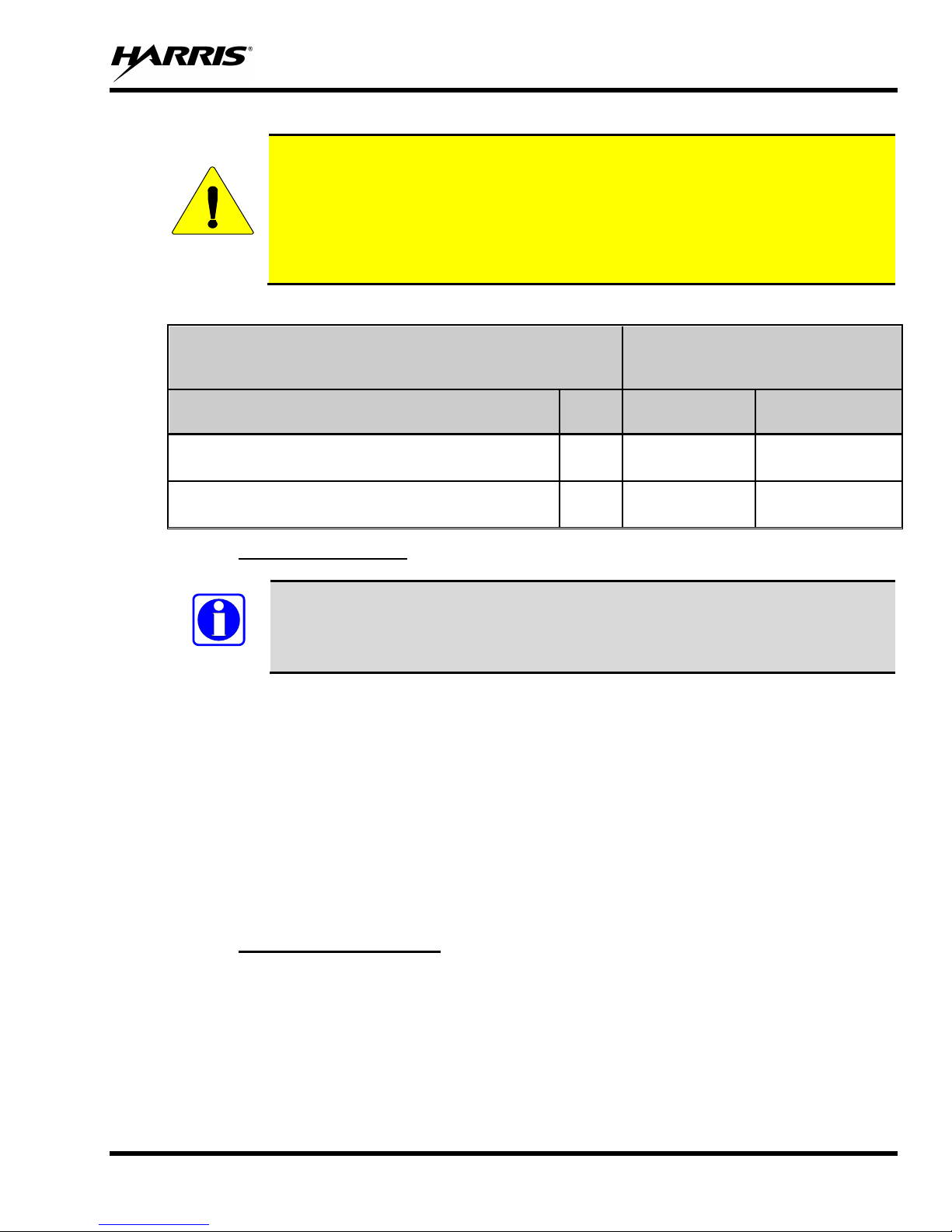
Table 1-2: MPE Minimum Distance Calculation for Nomadic Client Installations
4.9 GHz CLIENT WITH 0.5 WATT OUTPUT IN NOMADIC OPERATION
(MOUNTED IN A VEHICLE) USING THE SPECIFIED ANTENNA AND
MOUNTS
ANTENNA & MOUNT
Antenna: MAXRAD (B)MEFC49005HF (5.5 dBi gai n)
Mount: MAXRAD MHFML195C (Permanent)
Antenna: MAXRAD (B)MEFC49005HF (5.5 dBi gai n)
Mount: MAXRAD GMHFML195C (Magnetic)
(Watts)
< 3.0 20 cm 20 cm
< 3.0 20 cm 20 cm
ERP
RECOMMENDED MINIMUM LATERAL
DISTANCE FROM TRANSMITTING ANTENNA
CONTROLLED UNCONTROLLED
1.4.1 Nomadic Antennas
This device must not be co-located or operated in conjunction with any other antenna or
transmitter.
Install the radio’s antenna (refer to Table 1-2 for applicable antenna part numbers) in the center of the
vehicle’s roof. These nomadic antenna installation guidelines are limited to metal body motor vehicles or
vehicles with appropriate ground planes. The antenna installation should additionally be in accordance
with the following:
• The requirements of the antenna manufacturer/supplier included with the antenna.
• Installation instructions in this manual, including any minimum antenna cable lengths.
• The installation manual providing specific information of how to install the antennas to facilitate
recommended operating distances to all potentially exposed persons.
• Use only the Harris approved/supplied antenna(s) or approved replacement antenna. Unauthorized
antennas, modifications, or attachments could damage the radio and may violate FCC regulations.
1.4.2 Approved Accessories
This radio has been tested and meets the FCC RF guidelines when used with the Harris accessories
supplied or designated for use with this product. Use of other accessori es may not ensure compliance
with the FCC’s RF exposure guidelin es, and may violate FCC regulations.
For a list of Harris approved accessorie s refer to the product manuals, the Products and Services Catalog,
or contact Harris at 1-800-528-7711.
13
Page 15

MM-018965-001
WARNING
1.4.3 Occupational Safety Guidelines and Safet y Traini ng Information
To ensure bodily exposure to RF electromagnetic energy is within the FCC allowable limits for
occupational use. Always adhere to the following basic guidelines:
1. The radio should only be used for necessary work-related communications.
2. The radio should only be used by authorized and trained personnel. It should never be operated by
children.
3. Do not attempt any unauthorized modification to the radio. Changes or modifications to the radio
may cause harmful interference and/or cause it to exceed FCC RF exposure limits. Only qualified
personnel should service the radio.
4. Always use Harris authorized accessories (antennas, cont r ol heads, speakers/mics, etc.). Use of
unauthorized accessories can cause the FCC RF exposure compliance requirements to be exceeded.
The information listed above provides the user with information needed to make him or her aware of a RF
exposure, and what to do to assure that this radio operates within the FCC exposure limits of this radio.
1.4.4 Common Hazards
The operator of any mobile radio should b e aware of certain hazards common to
the operation of vehicular radio transmissions. Possible hazards include but are
not limited to:
• Explosive Atmosph eres — Just as it is dangerous to fuel a vehicle whi le its motor running, be sure
to turn the radio OFF while fueling the vehicle. If the radio is mounted in the trunk of the vehicle,
DO NOT transport containers of fuel in the trunk.
Areas with potentially explosive atmosphere are often, but not always, clearly marked. Turn the radio
OFF when in any area with a poten tially explosiv e atmosphere. It is rare, but not impossible that the
radio or its accessories could generate sp ar ks.
• Interference To Vehicular Elect ronic Systems — Electronic fuel injectio n systems, electro nic anti-
skid braking systems, electronic cruise control systems, etc., are typical of the types of electronic
devices that can malfunction due to the lack of protection from radio frequency (RF) energy present
when transmitting. If the vehicle contains such equ ipment, consult th e dealer for the make of veh icle
and enlist his aid in determining if such electronic circuits perform normally when the radio is
transmitting.
• Electric Blasti ng Caps — To prevent accidental detonatio n of electric blasting caps, DO NOT use
two-way radios within 1000 feet (305 meters) of blasting operations. Always obey the “Turn Off
Two-Way Radios” (or equivalent) signs posted wh ere electric blasting caps are being used. (OSHA
Standard: 1926.900).
• Radio Frequency Energy — To prevent burns or related physical injury from radio frequency
energy, do not operate the transmitter when any one outside of t he vehicle is within the minimum safe
distance from the antenna as specified in Table 1-1. Refer to Section 1.2 for additional information.
• Vehicles Powered By Liquefied Petroleum (LP) Gas — Radio in stallation in vehicles powered by
liquefied petroleum gas, where the LP gas container is located in the trunk or other sealed-off space
within the interior of the vehicle, must conform to the National Fire Protection Association standard
NFPA 58. This requires:
14
Page 16

MM-018965-001
CAUTION
The space containing the radio equipment must be isolated by a seal from the space containing
the LP gas container and its fittings.
Outside filling connections must be used for the LP gas container.
The LP gas container space shall be vented to the outside of the vehicle.
• Vehicles Equipped with Airbags — For driver and passenger safety, avoid mounting the radio or
any other component above or near airbag deployment areas. In addition to driver-side and
passenger-side front-impact airbags, so me vehicles may also be equipped with side-impact airbags.
For occupant safety, verify the location of all airbags within the vehicle before installing the radio
equipment.
1.4.5 Operating Rules and Regulations
Two-way FM radio systems must be operated in accordance with the rules a nd regulations of the local,
regional, or national government.
In the United States, the mobile radio must be operated in accordance with the rules an d regu lati on s of the
Federal Communications Commission (FCC). Operators of two-way radio equipment must be thoroughly
familiar with the rules that apply to the particular type of radio operation. Following these rules helps
eliminate confusion, assures the most efficient use of the existing radio channels, and results in a
smoothly functioning radio network.
Under U.S. law, operation of an unlicensed radio transmitter within the jurisdiction of
the United States may be punishable by a fine of up to $10,000, imprisonment for up to
two (2) years, or both.
When using a two-way radio, remember these rules:
• It is a violati on of FCC rules to interrupt any distress or emergency message. The radi o operates in
much the same way as a telepho ne “party line.” Ther efore, always li sten to make sure th e channel is
clear before transmitting. Emergency calls have priority over all other messages. If someone is
sending an emergency message – such as reporting a fire or asking for help in an accident, do not
transmit unl ess assistance can be offered.
• The use of profane or obscene language is prohibited by Federal law.
• It is against the law to send false call letters or false distress or emergency messages. The FCC
requires keeping conversations brief and confines them to business. To save time, use coded
messages whenever possible.
• Using the radio to send personal messages (except in an emergency) is a violation of FCC rules. Send
only essential messages.
• It is against Federal law to repeat or otherwise make known anything overheard on the radio.
Conversations between others sharing the channel must be regarded as confidential.
• The FCC requi res self-identification at certain specific times by means of call lett ers. Ref er to the
rules that apply to the particular type of operation for the proper procedure.
• No changes or adjustments shall be made to the equipment except by an authorized or certified
electronics technician.
15
Page 17

MM-018965-001
NOTE
In areas where transmission or reception is poor, communication improvement may
sometimes be obtained by moving a few yards in another direction, or moving to a higher
1.4.6 Mobile Operating Tips
The following conditions tend to reduce the effective range of two-way radios and should be avoided
whenever possible:
• Operating the radio in areas of low terrain, or while under power lines or bridges.
• Obstructions such as mountains and buildings.
elevation.
16
Page 18

MM-018965-001
2 INTRODUCTION
2.1 ABOUT THIS MANUAL
This manual is written for the co mmunications professional responsible for installing and maintaining the
VIDA Broadband Subscriber Station (Client) equipment installed as part of a VIDA Broadband 4.9 GHz
Broadband Network.
This manual provides an overview of the VIDA Broadband Client equipment used in the VIDA network.
Equipment specifications and instructions are discussed for installing VIDA Broadband Clients and
auxiliary equipment in various mobile and fixed applications.
2.2 REFERENCE MANUALS
It may be necessary to consult one or more of the following manuals when installing, operating, or
maintaining a VIDA Broadband Network.
Table 2-1: Related Documentation
DOCUMENTATION MANUAL
NUMBER
VIDA Broadband BAS/UAS User’s Manual MM-011540-001
RNM/CNM User’s Manual MM1000018633
VIDA Broadband System Manual MM-011541-001
VIDA Broadband Base Station Product Manual MM-009804 -001
VIDA Broadband Installation and Configuration Manual MM-014720-001
VIDA Broadband B510 Base Station Product Manual MM-016895 -001
VIDA Broadband MultiLink Station Product Manual MM-013752-001
VIDA Broadband Network Services Installation and Conf iguration Manual MM-014640-001
VIDA Broadband Basic Network Applications Programming Guide MM-014641-001
VIDA Broadband Systems Troubleshooting Guide MM-014642-001
VIDA Broadband Systems RF Planning Guide MM-015601-001
17
Page 19

MM-018965-001
2.3 GLOSSARY OF TERMS
The following Table is a list of terms used in this manual.
Table 2-2: Glossary of Terms
TERM DEFINITION
AES Advanced Encryption Standard
RSA Rivest, Shamir, and Adleman (creators of RSA Encryption format)
DES Digital Encryption Standard
DHCP Dynamic Host Configuration Protocol
EDACS Enhanced Digital Access Communicati ons S ystem
GPS Global Positioning Satellite
IEEE Institute of Electrical & Electronics Engineers
LMR Land Mobile Radio
MIB Management Information Base
QoS Quality of Service
SNMP Simple Network Management Protocol
TAC Technical Assistance Center
TFTP Trivial File Transfer Protocol
UAS Unified Administration System
UGS Unsolicited Grant Services
VIDA Voice, Interoperability, Data, and Access
WAN Wide Area Network
18
Page 20

MM-018965-001
3 DESCRIPTION
The 4.9 GHz VIDA Broadband Client is part of Harris’ VIDA Broadband network. The VIDA
Broadband Client may be installed in fixed or nomadic applications and is designed to operate using AC
or DC input voltage and communicate through a 100Base-TX Ethernet data port.
Figure 3-1: VIDA Broadband Client
3.1 SUBSCRIBER STATION CONFIGURATIONS
The 4.9 GHz VIDA Broadband Client is shown in Figure 3-1. The Client is housed in a ruggedized
enclosure suitable for nomadic or outdoor installations. The NEMA 4 housing satisfies IP66
requirements for outdoor deployments. The Client i s designed for multiple mounting configurations to
allow nomadic or fixed structure mounting.
The Client is available for fixed or nomadic applications and is approved for 5 or 10 MHz channel
bandwidth. The Client is designed to operate on 11 to 30 Vdc or 24 Vac and use a 100Base-TX Ethernet
data port configuration. However, a DC supply is recommended in all applications for cleaner and lowernoise power.
3.2 VIDA BROADBAND SYSTEM OVERVIEW
VIDA Broadband provides integrated public safety grade wireless broadband video and data services for
mission-critical applications. VIDA Broadband combines the security of the licensed 4.9 GHz public
safety frequency band with the robust 802.16 communications industry standard to create a true public
safety broadband network. With this state-of-the-art network, public safety customers can implement
applications such as streaming video, web applications, economical licensed LMR backhaul, and other
19
Page 21

MM-018965-001
bandwidth intensive applications. Since the network provides guaranteed Quality of Service (QoS), it is
especially suited for applications such as video surveillance, perimeter control, and mobile command.
VIDA Broadband is integrated with the VIDA network allowing seamless sharing of network resources,
including hardware network management and administration.
Figure 3-2: VIDA Broadband Network
The basic architecture of the 4.9 GHz VIDA Broadband network is a point-to-multipoint network. A
system consists of one or more base station(s) and at least one or more clients per base station as shown in
Figure 3-2. There are two configurations of client devi ces; fixed and nomadic. Fixed client devices ar e
usually mounted outdoors with directional antennas and have a range of up to 10 miles. Nomadic clients
are vehicle mounted and use an omnidirectional antenna. The range of a nomadic client to base station is
typically a few hundred meters.
The VIDA Broadband Base Station implements the 802.16e-2005 OFDM protocol to deliver an over-theair throughput from 3 to 19 Mbps (for 5 MHz channel) and 3 to 38 Mbps (for 10 MHz channel). Al l
communication over the wireless channel is scheduled by the base station, with contention slots provided
20
Page 22

MM-018965-001
for the VIDA Broadband Client to request bandwidth. This coordinated scheduling feature of the
protocol provides significant advantages such as:
• Minimizes cont ention between clients.
• Maximizes channel utilization.
• Maximizes ability to coordinate frequency usage among users.
• Enables guaranteed bandwidth services for critical appl ications.
21
Page 23

MM-018965-001
NOTE
Save the shipping cartons and packing materials in case the equipment needs to be
CAUTION
damaged, loose, or missing parts. Examine the RF connector(s), circular power
unauthorized attempts to repair or modify this equipment will void the warranty and
4 UNPACKING AND CHECKING EQUIPMENT
Before unpacking, installing or operating the VIDA Broadband equipment, read this section of the manual
thoroughly. It contains detailed unpacking and handling instructions, and safety precautions to protect
users and equipment.
4.1 UNPACKING EQUIPMENT
The VIDA B roadband equipment may be shipped in separate transit packages. The associated cabling
and accessories for each unit, if any, may also be shipped in separate containers.
When unpacking the equipment, check the contents against the packing list. Contact your Harris VIDA
Broadband equipment representative and the carrier if any discrepancies are noted.
shipped back to the Harris for service.
4.2 INSPECTING AND INVENTORYING EQUIPMENT
Carefully unpack the equipment and examine each item. If there i s any damage to the equipmen t, contact
the carrier immediately and have th eir representativ e verify the damage. If yo u fail to report the shippin g
damages immediately, you may forfeit any claim against the carrier.
After removal from the carton, examine the VIDA Broadband equipment for broken,
connector and ground lug for cracks, bent or damaged threads, or damage to any paint or
seals. If any are noted, contact t he Harris Customer Resource Cen ter immediately. Any
could create a safety hazard.
4.3 ITEMS INCLUDED
The following items are included in the Client package:
• VIDA Broadband Client (Part # 14000-1000-01)
• Mounting Bracket (Part # 14000-0067-01)
• Mating Power Plug (Part # CN-014934)
• Mating Network Plug (Part # J68-0021-001)
• Strain Relief Fitting (Part # E40-0021-001)
• Mounting Hard war e Kit includes four each –8-32 x 3/8” SS Screw wi th washer (Part # H21-
0001-206)
22
Page 24

MM-018965-001
CAUTION
5 PLANNING A FIXED STATION INSTALLATION
5.1 GENERAL
Careful planning a preparation of any installation will always benefit the end result. Please refer to the
VIDA Broadband Installation Manual, MM-014720-001 for detailed planning and installation
instructions.
1. Always read and follow all installation inst ructions, local and national building and electrical codes,
and general safety rules.
2. Before beginning the installation, collect information from the Site Deployment Order (SDO) specific
to the site access such as:
• Permission to access t he site.
• Important contact names and telephone numbers.
• Location of and directions to the site.
• Keys and/or lock combinations to access the site and equipment shelter (if any), or points of
contact to obtain them.
• Site entry alarm system pass-codes and/or disable keys.
• Information about work practices needed to work safely at the site.
3. Other important information that may or may not be included on the SDO includes:
• Type of mounting—metal pole, wooden pole, tower base, ext er ior wall, etc.
• Drawing or description of each site showing how the equipment is to be installed.
• Applicable inspections completed (pole installation, electrical, local build code, etc.).
• Installer must b e awar e of other transmitters and receivers on site that could cause interference to,
or be interfered with, by the broadband equipment. Strong signals from, or to, co-located
equipment may inflict permanent damage t o either device.
VIDA Broadband equipment has a maximum allowed input power of 0 dBm in the 4.9 to
4.99 GHz band. Although other frequencies may have a higher threshold, any signal, at
any frequency, above 0 dBm presented to the Broadband equipment should be cleared by
the factory prior to installation.
4. We recommend pre-staging the equipment to become familiar with the specific hardware and cabling,
tooling, and supplies that are needed to complete the installation.
5.2 SITE EVALUATION
Before installing the VIDA Broadband Client, the System Engineer and Installer should plan the site
installation. Since higher RF frequencies do not readily pass through trees or buildings, consideration
should be given to the following:
• Ensure there are no obstructions (such as buildings or trees) in the radio path between base station
and client units.
23
Page 25

MM-018965-001
• Ensure that any future building construction or tree growth will not obstruct the radio path.
• Ensure there is suff icient clearance around the Fresnel Zone so there is minimal interference from
obstacles along the radio propagation path.
• Ensure the installation adheres to any local and national building codes and permits.
• Ensure sufficient electrical power is available at the install ation site.
• When using directional antennas, align the antenna to maximize the Received Signal Strength
Indication (RSSI) from the base station.
• Ensure the area around an omnidirectional antenna is clear (at l east 30 inches) so as not to distort
the RF pattern.
• Locate the client away from any sources of interference that could degrade the performance of the
equipment. Consult the RF Planning Guide, MM-015601-001 for additiona l inf or m a t ion.
• Ensure the base station and clients are within each other’s maximum RF coverage range.
• Ensure maximum standard Cat-5 cable length connecting the client to the Ethernet LAN is 100
meters (328 ft.).
5.3 ELECTRICAL POWER
The input voltage source required depends on the model being installed. For example, clients use either
11 to 30 Vdc or 24 Vac +/- 10%.
The VM-WM4900-CL001 client supports power over Ethernet (IEEE 802.3-2005 compliant).
Careful consideration should be given regarding the voltage drop across the selected power cabling to
maintain the input power requirements. If a backup power source is desired, it must be provided by an
external backup power source.
DC Power Source Options
We recommend using power supplies that are FCC Part 15 Class A or B compliant. Using power
supplies that are not compliant could be in violation of FCC Regulations. It is the installer’s
responsibility to ensure the installation meets FCC Regulations.
5.4 SITE GROUNDING
Installers should review the recommended grounding procedures in the Site Grounding and Lightning
Protection Guidelines Manual, AE/LZT 123 4618/1 and ensure a suitable gro und is installed between th e
station ground lug and earth ground. Grounding must also be in compliance with any local and national
electrical codes.
24
Page 26

MM-018965-001
5.5 SURGE PROTECTION
When installing a VIDA Broadband Base Station, MultiLink Station, or Subscriber Station you should
always install external surge protectors to protect the system components from lightning or transient
damage. Table 5-1 lists surge protectors that have been tested in VIDA Broadband systems and are
available from Harris. Detailed descriptions of these devices can be found in the VIDA Broadband
Installation Manual, MM-014720-001.
Table 5-1: Surge Protection Options
PART NUMBER DESCRIPTION
PT-016508-001 RF Port Surge Protector, Coax, Type N, 4.9 GHz.
PT-016508-002 GPS Port Surge Protector, Coax, TNC.
PT-016508-003 Cat5e, RJ-45, Data Port Surge Protector.
PT-016508-004 Surge Protector, DC, Wire, 27 Vdc
PT-016508-005 Surge Protector, DC, Wire, 54 Vdc
PT-016508-006 Surge Protector, AC/DC, Wire, 24 Vac/ 30 Vdc
PT-016508-007 Surge Protector, Coax, BNC, CCTV, and PTZ Data
PT-016508-008 Surge Protector, Coax, BNC, CCTV
PT-016508-009 Surge Protector, AC, wire, 120 Vac
5.6 ANTENNA OPTIONS
The VIDA Broadband Client allows users to choose many different antenna types to meet their
application requirements. For fixed installations, a directional antenna can significantly extend the
effective range of the Client. For example, a high gain directional antenna may improve signal quality
over a long distance while antennas with less gain or omnidirectional may perform better in densely
patterned city regions.
Three basic methods exist for mounting the base station antenna used with a Client. Two of the three
methods mount the antenna directly on the Client and the third requires a separate mounting location and
hardware. The three methods include the following:
• Direct or remote mounting of an omnidirectional antenna on the subscriber station
• Direct or remote mounting of a directional antenna on the front face of the subscriber station, or
• Direct or remote mounting of an antenna through the connection of an RF cable to the subscriber
station.
The VIDA Broadband Subscriber Stations allow users to choose from variety of antenna types and
installation configurations.
25
Page 27

MM-018965-001
NOTE
VIDA Broadband equipment is designed to use directional antennas with an antenna
5.6.1 Antenna Requirements
There are several basic “types” of antennas. Each type has certain advantages and disadvantages for
particular applications in microwave and broadband wireless networks. Antennas and any associated
cabling which connects the antenna to the Broadband equipment comprise an “Antenna System.” In this
Antenna System all cable loss is subtracted fro m the antenna gain, the result being the Effective Antenna
System gain. Generally, the antenna system used with a VIDA Broadband device must meet the
following requirements:
Omnidirectional Antenna: Vertical or Horizontal Polarization
9 dBi Effective Maximum System Gain
Directional Antenna System: Linear Vertical or Horizontal
26 dBi Effective Maximum System Gain
(Reduction of Transmitter Power is required if the Effective Maximum
Antenna System Gain is greater than 26 dBi for 5 MHz operation or
29 dBi for 10 MHz operation.)
System antenna gain is defined as the antenna gain minus any cable or other losses between the base
station antenna port and the antenna.
system gain up to 26 dBi in a point-to-point or point-to-multipoint configuration.
In 5 MHz applications, the Transmitter Output Power must be reduced if the Effective
Antenna System Gain is greater than 26 dBi. The power reduction needs to be at least
equal to or greater than the amount the antenna system gain exceeds 26 dBi.
In 10 MHz applications, customers may u se an Effective Maximum Antenn a System Gain
up to 29 dBi before a power reduction is required. This is because of the Broadband
equipment’s self imposed 27 dBm maximum power; verses a permitted power of 30 dBm.
5.6.2 Antenna Types
The following paragraphs describe th e d ifferent t yp es of ant ennas t hat can be us ed with VIDA Br oadb and
devices. Table 5-2 contains a list of approved antennas. Detailed antenna descriptions ca n be found in
the VIDA Broadband Installation Manual, MM-014720-001.
Omnidirectional Antennas
An omnidirectio nal antenna is a verti cal antenna. A vertical antenn a’s radiation pattern or signal rad iates
in all directions, losing power as the distance increases. Their radiation patterns are weaker directly
above or below the vertical plane. An omnidirectional antenna also picks up signals from all directions.
Grid Parabolic Antennas
The Grid parabolic antenna is a directional antenna that greatly reduces wind loading on a tower or other
mounting structures. Grid antennas have a lower front-to-back ratio than solid parabolic antennas. They
are also limited to a single pol arization. They ar e ideal in applica tions where the b est performance is no t
required and tower and wind loading are the main concern.
26
Page 28

MM-018965-001
Standard Parabolic Antennas
Standard parabolic antennas consist of a parabolic shaped reflector spun from a sheet of aluminum. Th e
parabolic shape focuses energy at t he feed point of the antenna. The parabolic antennas ha ve a narrow
focused beam of energy and relatively high gain compared to many other types of antennas. These
antennas will have a mounting system to attach the antenna to a pipe or tower leg.
High Performance Antennas
High Performance antennas are for med of aluminum, which is spun to preci se tolerances. Then a shroud
is also fabricated of aluminum and fitted with a planar radome to protect the feed and provide for a
significant reduction in side lobes. Ofte n manufacturers will u se absorb er material to i mprove the pattern
performance of the side lobes and front-to-back ratio.
Sector Antennas
Sector antennas are designed to provide segmented RF coverage over a selected (sector) area; sector
antennas deliver a wider beamwidth than point-to-point parabolic antennas. Antenna configurations can
consist of flat panel micro strip and slot radiati ng designs, as well as traditio nal parabolic configuration s.
Some common horizontal beamwidths used include 60, 90, 120, and 180 degrees.
Flat Panel Antennas
Flat panel antennas are designed for point-to-point and point-to-multi point applications. Typically, flat
panel antennas are designed to be li ghtweight, easy to install, aligned and durable for years of reliable
service. These antennas are ideal for concealment in many architectural environments. In addition to
pole mounting, the approved panel antenna can be mounted directly to the VIDA Broadband client.
Table 5-2: Antenna Options
Part Number Description
AN-013386-001 Antenna, Dish, 2 ft, 26.6 dBi, Type N Connector
AN-013386-002 Antenna, 90 degree Sector Panel, 16 dBi, Vertical polarization, Type N Connector
AN-013386-003 Antenna, Sector, 90 degree, 16 dBi, Horizontal, Type N Connector
AN-013386-004 Antenna, 60 degree Sector Panel, 17 dBi, Vertical polarization, Type N Connector
AN-013386-005 Antenna, Sector, 60 degree, 17 dBi, Horizontal, Type N Connector
AN-013386-006 Antenna, Grid, 2 ft, 26.4 dBi, Type N Connector
AN-013386-007 Antenna, Dish, 1 ft, 21.2 dBi, Type N Connector
AN-013386-008 Antenna, 10.5 degree Sector Panel, 1 ft, 21 dBi, Type N Connector
AN-013386-009 Antenna, Omnidirectional, 8 dBi, 16 degree, Type N Connector
AN-013386-010 Antenna, Dish, 2 ft, 6 degree, 27.7 dBi, Type N Connector
AN-013386-011 Antenna, Nomadic, Omnidirectional, Vertical polarization, 18 degree, 5.5 dBi, Ty pe N
Connector
AN-013386-012 Antenna, Omnidirectional, 8 degree, 9 dBi, Type N Connector
AN-013386-013 Antenna, Panel, 9 degree, 15 x 13 in., 20 dBi, Type N Connector
AN-013386-014 Antenna, 4.9 -5.85 GHz, 12 dBi, 180 Degree Sector Panel with type N Connector.
AN-013386-015 Antenna, 4.94-4.99 GHz, 15 dBi, 120 Degree Sector Panel with type N Connector.
27
Page 29

MM-018965-001
5.7 CLIENT MOUNTING
The VIDA Broadband Client is designed for pole or structure mounting. Pole mounting a Client may
include mounting the unit onto a horizontally suspended light post or side arm, or a vertical telephone
pole, mast pipe or tower leg. Mounting on a structure requires using an optional mounting plate.
Each subscriber station package includes a mounting bracket (14000-0067-01) and necessary hardware
for attaching the brackets to the units. The mounting brackets accommodate pole diameters of 1½ inches
and larger.
The subscriber station (client) can al so be mounted to a flat surface, su ch as a wall, directly or usi ng the
mounting bracket, shown in Figure 6-1.
Installers should refer to the VIDA Broadband Installation Manual, MM-014720-001 for detailed
installation instructions.
28
Page 30

MM-018965-001
WARNING
WARNING
WARNING
6 PLANNING A NOMADIC CLIENT INSTALLATION
This section provides general information regarding installation of the VIDA Broadband Client in
nomadic station configurations. For best results, the client should be installed by one of the many Harris
Authorized Service Centers located throug hout the United States. Their experienced service personnel
can provide a proper radio installation and make any final adjustments that may be needed.
Before starting the installation, plan carefully to ensure the installation meets the following requirements:
• Safe for the operat or and passengers.
• Away from airbag deployment area.
• Convenient for the operator to use.
• Neat, safe and clean.
• Protected from water damage.
• Easy to service.
• Cable connect ions are accessible.
• Out of the way of auto mechanics.
• Out of the way of passengers.
Vehicular Electronics - Electronic fuel injection systems, electronic a nti-skid braking
systems, electronic cruise control systems, etc., are typical of the types of electronic
devices which may be prone to malfunction due to the lack of protection from radio
frequency energy present when a radio is transmitting. If the vehicle contains such
equipment, consult the dealer to determine if such electronic equipment will perform
normally when the radio is transmitting.
Air Bags – For driver and passenger safety, avoid mounting the radio above or near
airbag deployment areas. Note that vehicles may contain front driver and passenger
side airbags as well as side airbags. For occupant safety, verify the location of all
airbags before installing radio equipment.
For passenger safety, mount the radio securely so that the unit will not break loose in
the event of a collision. This is especially important in station wagons, vans, and
similar type installations where a loose radio could be extremely dangerous to the
vehicle occupants.
When determining a mounting location for the client and associated peripherals, avoid high traffic
environments within the passenger compartment, trunk, or other compartment where feet, tools or other
objects may accidentally damage cable connecti ons. The client and other peripherals should be mounted
such that connectors and other fragi le components face away from high traffic areas, yet accessi ble for
servicing.
Also, careful attention must be given to ventilation and heat dissipation. The client should be mounted
with the heat sink fins vertically positioned an d ample air space around the unit.
29
Page 31

MM-018965-001
WARNING
6.1 RECOMMENDED KITS AND ACCESSORIES
We recommend using the following parts and accessories during installation of the client in a nomadic
configuration.
6.1.1 Mounting Bracket
The mounting bracket 14000-0067-01, shown in Figure 6-1, attaches to the bottom of the client and
provides easy installation of the client in a variety of app licatio ns. Attach the brack et to t he clien t using
the hardware provided.
Figure 6-1: Mounting Bracket
6.1.2 DC Power Cable Kit
The 4.9 GHz client may be install ed ONLY in vehi cles where th e negative battery p ost
is connected to the chassis of the vehicle (NEGATIVE GROUND ONLY).
The Fuse Distribution Rail Kit FS23057 provides the necessary hardware to wire up the Standard client to
a vehicle’s power system. This kit provides an ATC st yle fused common buss lead that is designed to
connect to the vehicle’s battery. The fused buss lead provides power to a Fuse Distribution Rail
assembly. This assembly may be mounted nearby the client and, if necessary, be expanded to power
multiple hardware components.
30
Page 32

MM-018965-001
Table 6-1: Fuse Distribution Rail Kit
KIT NUMBER QTY/DESCRIPTION PICTORIAL
FS23057
FS23058
Kit, Fuse Distribution Rail. Includes:
(1) Fuse Distribution Rail Assembly
(1) In-Line ATC Fuse Holder
(1) 15-Amp ATC Fuse
(1) 30-Amp ATC Fuse
20 Feet of 10-AWG Red Wi re
1 Foot of 10-AWG Blac k Wire
(1) Moisture-Resistant Butt Splice
(2) 3/8-Inch Ring Terminals.
Kit, Fuse Distribution Accessory.
Includes:
(1) Fuse Block
(1) Protective Marker
(1) Fuse Block Jumper
(1) 5-Amp ATC Fuse
(1) 15-Amp ATC Fuse
31
Page 33

MM-018965-001
CAUTION
damaging vital parts (fuel tank, transmission housing, etc.) of the
vehicle when drilling mounting holes. Always check to see how far the mounting
CAUTION
holes must be drilled, remove all metal shavings from drilling holes before
6.2 NOMADIC STATION ANTENNA OPTIONS
The recommended nomadic antenna model is the AN-013386-011. Electrically, the antenna requi res no
ground plane to meet VSWR performance specifications. However, it may be necessary to use this
antenna with a ground plane to meet MPE requirements. Low loss high frequency permanent and
magnetic mount cable kits, listed in Table 6-2, are also available.
Table 6-2: Nomadic Antenna and Mounts
PART NUMBER DESCRIPTION PICTORIAL
AN-013386-011
Antenna, collinear, elevated
feed,
MAXRAD:
5.5 dBi, no ground plane.
MEFC49005HF
MAXRAD:
MHFML195C
MAXRAD:
GMHFML195C
Permanent mount, 17 ft. Cable,
TNC male (loose).
Magnetic Mount, 17 ft. Cable,
TNC male (attached).
6.3 INSTALLING THE NOMADIC CLIENT
Please refer to the installation instructions contained in the VIDA Broadband Installation Manual, MM014720-001. This manual provides detailed instructions for installing and configuring a nomadic client.
Be careful to avoid
screws will extend below the mounting surface before installing.
If pilot
installing screws.
32
Page 34

MM-018965-001
1
2
PWR(Return)
PWR+
(11-30 Vdc)
Hot (16-26 Vac)
Neutral
1
2
7 SUBSCRIBER STATION CONNECTIONS
7.1 POWER CONNECTIONS
Power is supplied to the client through a 2-pin connector. A #12-16 Socket Multi-Con-X mating
connector kit, CN-014934 is supplied with the unit. A pre-made 2/12 AWG Power Cable assembly, CA014984-XXXXX or CA-014988-XXXXX, is availab le in various l engths. Refer to t he VIDA Broadband
Installation Manual, MM-014720-001 for details.
7.1.1 Subscriber Station DC Connections
Table 7-1: Client DC Power Connector
CONNECTION PIN POWER CONNECTOR
PWR+ (+11 to +30 Vdc) 1
PWR- (Return) 2
7.1.2 Subscriber Station AC Connections
T he AC supply must be isolated fr om AC mains; the use of an isolating step-down
transformer is necessa r y. T he AC supply must not have a gr ound path; ground
should be supplied through a separ ate wire to the gr ounding stud. F ai lur e to
observe this warning may r esult in electrical shock or damage to equipment.
Table 7-2: Client AC Power Connector
CONNECTION PIN CLIENT AC POWER CONNECTOR
HOT (16 to 26 Vac) 1
33
Page 35

MM-018965-001
Network Port
Power
Antenna
CAUTION
Figure 7-1: VIDA Broadband Client Interface Diagram
7.2 NETWORK/DATA CONNECTIONS
Network connections are made using a standard Ethernet RJ-45 protocol connection. All DATA
connectors are industrial grade, rugged, UV rated, weatherproof, dustproof and made for use in extreme
electrical and climatic conditions. Each connector meets the IP67 industrial standard for weatherproof
and dustproof electrical connections.
When installing cables, ensure they are n ot under any stress, a service loop is maintai ned,
and the cables are restrained according industry best practices.
To connect the Data cable:
1. Select proper length Ethernet cable. Instructions f or selecting and fabricating Ethernet cabl es are
provided in the VIDA Broadband Installation Manual, MM-014720-001.
34
Page 36

MM-018965-001
NOTE
WARNING
NOTE
2. Connect one end of the cable to the LAN connection.
3. Mate the other end of the Data cable to the station data connector by visually aligning the connector
key and firmly push and turn the outer locking ring clockwise until it clicks.
4. Be sure to install a dust cap on any ports not being used.
5. For Cat5e copper Ethernet cables, install a grounding kit within six inches of the unit and then every
75 feet. Refer to the Site Grounding and Lightning Protection Guidelines Manual,
AE/LZT 123 4618/1 for additional details on proper grounding techniques.
The Ethernet cable should be grounded at the unit and then every 75 feet until terminated
at the surge suppressor. Refer to the VIDA Broadband Installation Manual,
MM-014720-001 for grounding kit recommendations.
7.3 GROUNDING STUDS
A grounding connection is provided on the client. For safety purposes, earth ground and lightning
protection connections should be made as required by local ordinances and the Site Grounding and
Lightning Protection Guidelines Manual, AE/LZT 123 4618/1.
7.4 ANTENNA CONNECTIONS
See Section 1.3 for further information regarding Maximum Permissible Exposure
(MPE) limits of RF radiation set by the FCC.
There are three basic methods for mounting a fixed station antenna. These methods include the
following:
• Direct or remote mounting of an omnidirectional antenna on the subscriber station
• Direct or remote mounting of a directional antenna on the front face of the subscriber station, or
• Direct or remote mounting of an antenna through the connection of an RF cable to the subscriber
station.
The RF cable connecting the subscriber station to the antenna should be kept as short as
possible. The cable should be constructed from a high quality heliax cable such as Andrew
LDF4-50A or equivalent.
If the distance between the radio equipment an d the antenna exceeds 30 feet, use a larger
low loss cable such as Andrew LDF5-50A or equivalent.
The 1/2" LDF 4-50A cable offers approximately 5.5 dB of loss per 100 feet and LDF 550A cable offers approximately 3.2 dB of loss per 100 feet.
The losses are in addition to any connector losses that may occur.
35
Page 37

MM-018965-001
7.4.1 Installing an Omnidirectional Antenna
An omnidirectional antenna may be mounted directly to the Client using the following procedure:
1. Connect an N-type male to male RF adapter (not included) to the omnidirectional antenna. Hand-
tighten the connector.
2. For Copper Clients, external lightning protection is required to provide maximum protection to the
site. Connect the optional lightning suppressor to the antenna assembly as shown in Figure 7-2.
A list of approved surge protection devices can be found in the VIDA Broadband Installation Manual,
MM-014720-001.
3. Connect the completed antenna assembly to the Client antenna connector.
Figure 7-2: VIDA Broadband Client Antenna with External Lightning Protection
7.4.2 Installing a Directional Antenna
A directional antenna can be mounted directly on the unit using the optional universal mounting bracket
kit. After the universal mounting bracket is attached, it can be adjusted to point the forward beam pattern
of the antenna in the direction needed for network connectivity. Refer to the VIDA Broadband
Installation Manual, MM-014720-001 for alignment instructions.
Four mounting holes are provided for mounting an antenna to the front cover housing of the subscriber
stations. These mounting holes are spaced at a 1.772" x 5.118" (45 mm × 130 mm) rectangular pattern
tapped to accept 1/4-20 UNC-2B hardware with a minimum hole depth of 0.31".
A low loss RF cable (not included) is needed to connect between the unit’s antenna connector and the
directional antenna. The RF cable and connectors must be capable of passing frequencies up to 5.2 GHz
with minimal loss.
36
Page 38

MM-018965-001
7.4.3 Remotely Mounting an Antenna
When installing an antenna remotely, always observe best practices and the antenna manufacturer’s
recommendations.
Refer to the VIDA Broadband Installation Manual, MM-014720-001 for installation instructions.
37
Page 39

MM-018965-001
NOTE
VIDA Broadband Systems
8 TROUBLESHOOTING AND SERVICING
There are no user serviceable components within the VIDA Broadband radio equipment
assemblies. These assemblies contain ESD sensitive components and should only be
serviced by Harris qualified personnel.
8.1 TROUBLESHOOTING
If a unit is suspected to be faulty or need servi ce and repair, perform the following checks:
1. Visually inspect the installation for obvious defects such as worn, weathered, or frayed cabling.
2. Verify that the unit is receiving sufficient voltage and current to the power input connector.
3. Replace any defective antenna or power source co mponents as required, and return any inoperable
Clients to the manufacturer for repairs.
Detailed troubleshooting information is available in the
Troubleshooting Guide, MM-014642-001.
8.2 TUNING AND ALIGNMENT
Every VIDA Broad band Client is fully aligned, including TX Frequency and RF Power Output, before
shipment to ensure compliance with various regulatory requirements and product performance. No
further tuning or alignment is required by the customer or installer during the installation process. Basic
control of the Client, including RF power output and channel assignment, is accomplished by the UAS
during site configuration. Refer to the VIDA Broadband Installation Manual, MM-014720-001 for
configuration and alignment instructions.
8.3 SERVICING
The Client is not a field repairable unit. If a unit is suspected to need servicing or re-alignment, then the
unit should be removed from service and returned to Harris for repairs. Periodic checks o f frequency and
modulation bandwidth should be performed during routine preventative maintenance checks.
38
Page 40

MM-018965-001
9 CUSTOMER SERVICE
9.1.1 Technical Support
The Technical Assistance Center (TAC) resources are available to help you with overall system
operation, maintenance, upgrades, and product support. TAC is your point of contact when you need
technical questions answered.
Product specialists, with detailed knowledge of product operation, maintenance, and repair, provide
technical support via a toll-free telephone number (in North America). Support is also available through
mail, fax, and e-mail.
For more information about technical assistance services, contact your sales representative, or call the
Technical Assistance Center directly at:
North America: 1-800-528-7711
International: 1-434-385-2400
FAX: 1-434-455-6712
E-mail:
PSPC_tac@harris.com
9.1.2 Customer Resource Center
If any part of the system equipment is damaged on arrival, contact the shipper to conduct an inspection
and prepare a damage report. Save the shipping container and all packing materials until the inspection
and the damage report are completed. In addition, contact the Customer Resource Center to make
arrangements for replacement equipment. Do not return any part of the shipment until you receive
detailed instructions from a Harris representative.
Contact the Customer Resource Center at:
North America:
Phone Number: 1-800-368-3277 (toll free)
Fax Number: 1-800-833-7592 (toll free)
E-mail:
International:
Phone Number: 1-434-455-6403
Fax Number: 1-434-455-6676
E-mail:
PSPC_CustomerFocus@harris.com
PSPC_InternationalCustomerFocus@harris.com
39
Page 41

MM-018965-001
Model Number:
Physical Characteristics:
Electrical Power:
Power over Ethernet, +24 Vdc (nominal) or 24 Vac
Environmental Specifications:
System Interfaces:
Data Plane:
100Base-TX
10 SPECIFICATIONS
10.1 GENERAL SPECIFICATIONS
VM-WM4900-CL001
Power Consumption: 6 Watts typical
Size (H x W x D): 8.2 × 4.9 × 1.6 in (20.9 × 12.4 × 4.1 cm)
Weight: 1.6 lbs (0.7 kg) (less mounting hardware)
Operating Temperature: -22°F to +140°F (-30°C to +60°C)
Storage Temperature: -40°F to +185°F (-40°C to +85°C)
Environmental (Enclosure): NEMA4
Altitude: 15,000 ft. (operational)
Management: 100Base-TX, 100Base-FX, or over the air
4.9 GHz RF: Type-N(f) connector
40
Page 42

MM-018965-001
Security Features:
Network Features:
PHY Characteristics:
MAC Characteristics:
10.2 DATA SPECIFICATIONS
Authentication: X.509 Digital Certificate
Authorization: RSA Public Key Encryption
Encryption: AES 128 bit
Management: SNMP
Convergence: IPv4
Configuration: DHCP, TFTP
PHY: OFDM 256 FFT
IEEE 802.3/Ethernet
Channel Bandwidth: 5 or 10 MHz
Modulation Rates: BPSK, QPSK (1/2, 3/4), 16QAM (1/2, 3/4),
64QAM (1/2, 3/4)
Duplexing: Time Division Duplexing (TDD)
Frame Durations: 5 msec, 10 msec
CP: 1/32, 1/16, 1/8, 1/4
Throughput: 1-19 Mbps for 5 MHz Channel
2-38 Mbps for 10 MHz Channel
Duplexing: Time Division Duplexing (TDD)
Service Classes Supported: Real-Time Polling Service (rtPS)
Non-Real-Time Polling Service (nrtPS)
Unsolicited Grant Service (UGS)
Best Efforts (BE)
10.3 TRANSMITTER SPECIFICATIONS
Frequency: 4.905-4.995 GHz
Channel Bandwidth: 5 or 10 MHz
41
Page 43

MM-018965-001
RF Power Output: 27 dBm maximum
Output Power Control: 50 dB
FCC ID: BV8WM4900CL
Industry Canada: 3670A-WM4900CL
Spectrum Mask: FCC Mask M (90.210)
10.4 RECEIVER SPECIFICATIONS
Frequency Band: 4.905-4.995 GHz
Channel Bandwidth: 5 or 10 MHz
Sensitivity at BER 10
E-6
:
BPSK -1/2: -96 dBm
QPSK -3/4: -89 dBm
16-QAM – 3/4: -83 dBm
Max RX Input Power: -30 dBm
Max/RX Input Power (no damage): 0 dBm
42
Page 44

MM-018965-001
WARRANTY
Please register this product within 10 days of purchas e. Registration validat es the warranty coverag e, and enables Harris t o
contact you in case of any safety notif i c ations issued for this product.
Registration can be made on-line at
the following:
U.S. & Canada:
Phone Number: 1-800-368-3277, Option 4 (toll free)
Fax Number: 1-434-455-6821
E-mail:
mailto:WarrantyClaims@Harris.com
International:
Phone Number: 1-434-455-6403
Fax Number: 1-434-455-6676
E-mail:
mailto:WarrantyClaims@Harris.com
A. Harris Corpora tion, a D ela ware Cor porati on, t hrough its RF Communicatio ns Divis ion (hereinafter "Seller") warr ants t o the
original purchaser for use (hereinafter "Buyer") that Equipm ent manufactured by or for the Sel ler shall be free from defect s
in material and workmanship, and shall conform to it s published specifi cations. With respec t to all non-Sell er Equipment,
Seller gives no warranty, and only the warrant y, if an y, given b y the manuf acturer s hall appl y. Rech argeab le batter ies are
excluded from this warranty but are warranted under a separate Rechargeable Battery Warranty (ECR-7048).
B. Seller’s obligat ions set forth in Paragraph C below shall apply on ly to failures to meet the above warranties occurrin g
within the following periods of t ime from date of sale to the Buyer and ar e conditioned on Buyer’s gi ving written notice t o
Seller within thirty (30) days of such occurrence:
1. for fuses and non-rechargeable batteries, operable on arrival only.
2. for parts and accessories (except as noted in B.1), ninety (90) days.
3. for P7300, P7200, P7100
(including V-TAC), M7100
4. for Unity
®
XG-100P, three (3) years.
5. for all other equipment of Seller’s m anufacture, one (1) year.
C. If any Equipment fails t o meet the foregoing warranties, Seller shall corr ect the failure at its option (i) by repairing any
defective or damaged part or parts thereof, (ii) by making available at Seller’s factory any necessary repaired or
replacement parts, or (iii) b y replacing the faile d Equipment with equival ent new or refurbished Eq uipment. Any repaired
or replacement part furnished hereunder shall be warranted for the r emainder of the warranty period of t he Equipment i n
which it is installed. Wher e such failure cannot be cor rected by Seller’s reasonable effor ts, the parties will negotiate an
equitable adjustment in price. Lab or to perform warrant y service will be prov ided at no charge during t he warranty perio d
only for the Equipment covered under Paragraph B.3 and B.4. To be eligible for no-charge labor, service must be
performed at Seller’s factory, by an Authorized Service Center (ASC) or other S ervicer approved for these purposes either
at its place of business during norma l business hours, for mobile or personal equipmen t, or at the Buyer’s location, for
fixed location equipment. Serv ice on f ixed l ocation equipme nt more th an thirt y (30) mi les fr om the Serv ice Cent er or oth er
approved Servicer’s place of business will include a charge for transportation.
D. Sell er’s obligations under Paragra ph C shall not apply to any Equipment , or part thereof, which (i) has been mod ified or
otherwise altered other than pursuant to Seller’s written instructions or written approval or, (ii) is normally c onsumed in
operation or, (iii) has a normal life inherently shorter than the warrant y periods specified in Paragraph B, or (iv) is not
properly stored, installed, used, maintained or repaired, or, (v) has been subjected to any other kind of misuse or
detrimental exposure, or has been involved in an accident.
E. The preceding paragraphs set forth the exclusive remedies for claims based upon defects in or nonconformity of the
Equipment, whether the claim is in contract, warranty, tort (including n egligence), st rict liabilit y or other wise, and however
instituted. Upon the expiration of the warranty period, all such liability shall terminate. The foregoing warranties are
exclusive and in lieu of all other warranties, whether oral, written, expressed, implied or statutory. NO IMPLIED OR
STATUTORY WARRANTIES OF MERCHANTABILITY OR FITNESS FOR PARTICULAR PURPOSE SHALL APPLY. IN
NO EVENT SHALL THE SELLER BE LIABLE FOR ANY INCIDENTAL, CONSEQUENTIAL, SPECIAL, INDIRECT OR
EXEMPLARY DAMAGES.
Harris Corporation Harris Corporation
RF Communications Division RF Communications Division
221 Jefferson Ridge Parkway 1680 University Avenue
Lynchburg, VA 24501 Rochester, NY 14610
1-585-244-5830
www.pspc.harris.com/CustomerService or by contacting Harris Warr anty Administration at
IP
IP
, M5300 and M3300 radios, two (2) years, effective 10/01/2007.
, P5400, P5300, P5200, P5100, P3300, M7300, M7200
This warranty applies only within t he United States.
ECR-7047L
43
Page 45

7711
Public Safety and Professional Communications | www.pspc.harris.com
221 Jefferson Ridge Parkway | Lynchburg, VA USA 24501 | 1-800-528-
 Loading...