

HARRIS VIDA-BB-CL Users Manual

Rhein Tech Laboratories, Inc. Client: M/A-COM, Inc.
360 Herndon Parkway ID’s: BV8VIDA-BB-CL/3670A-VIDABBCL
Suite 1400 Model: VIDA Broadband High Power Client
Herndon, VA 20170 Standards: FCC Pt 90/IC RSS-111
http://www.rheintech.com
RTL Report #: 2008221
Appendix C: Manual
Please refer to the following document.
27 of 29

Installation and Configuration Manual
MM-014720-001
Rev. A, Feb/09
VIDA Broadband Equipment

MM-014720-001, Rev. A
MANUAL REVISION HISTORY
REV DATE REASON FOR CHANGE
- Jul/08 Initial release.
A Feb/09 Added the MultiLink, B510 BS information, approved antenna options, and instructions
for using the base station Web page.
Tyco Electronics Technical Publications would particularly appreciate feedback on any errors found in this document and
suggestions on how the document could be improved. Submit your comments and suggestions to:
Tyco Electronics Wireless Systems fax your comments to: 1-434-455-6851
Technical Publications or
221 Jefferson Ridge Parkway e-mail us at: techpubs@tycoelectronics.com
Lynchburg, VA 24501
CREDITS
Andrew is a registered trademark of CommScope, Inc.
IndigoVision is a trademark of IndigoVision Group plc.
Windows is a registered trademark of Microsoft Corporation.
Conxall and Multi-Con-X are registered trademarks of Conxall Inc.
Band-it is a registered trademark of BAND-IT-IDEX, Inc., a unit of IDEX Corporation.
All other brand and product names are trademarks, registered trademarks, or service marks of their respective holders.
NOTICE!
The technology embodied in this product is protected by various intellectual property rights including patent rights,
copyrights, and trade secrets of Tyco Electronics Corporation and its suppliers. All Software provided is licensed not sold
and any user of this software and/or technology must execute and comply with the Software License Agreement provided by
Tyco Electronics, governing the use and restrictions on same. User is expressly prohibited from attempting to decompile,
reverse engineer, or disassemble any object code provided, or in any other way convert such object code into humanreadable form. User agrees to comply with all restrictions set forth in the license agreement and to use software only for the
purposes provided.
This product conforms to the European Union WEEE Directive 2002/96/EC. Do not dispose of this product
in a public landfill. Take it to a recycling center at the end of its life.
The software contained in this device is copyrighted by M/A-COM, Inc. Unpublished rights are reserved under the
copyright laws of the United States.
This manual covers M/A-COM, Inc., products manufactured and sold by M/A-COM, Inc.
Repairs to this equipment should be made only by an authorized service technician or facility designated by the supplier.
Any repairs, alterations or substitutions of recommended parts made by the user to this equipment not approved by the
manufacturer could void the user's authority to operate the equipment in addition to the manufacturer's warranty.
This manual is published by M/A-COM, Inc., without any warranty. Improvements and changes to this manual necessitated by typographical errors,
inaccuracies of current information, or improvements to programs and/or equipment, may be made by M/A-COM, Inc., at any time and without notice.
Such changes will be incorporated into new editions of this manual. No part of this manual may be reproduced or transmitted in any form or by any means,
electronic or mechanical, including photocopying and recording, for any purpose, without the express written permission of M/A-COM, Inc.
Copyright© 2008-2009 M/A-COM, Inc. All rights reserved.
2

MM-014720-001, Rev. A
TABLE OF CONTENTS
Page
1. PREFACE ....................................................................................................................................... 9
1.1 ABOUT THIS MANUAL......................................................................................................................... 9
1.2 REFERENCE MANUALS ....................................................................................................................... 9
1.3 CONVENTIONS AND SAFETY SYMBOLS ....................................................................................... 10
1.4 CUSTOMER SERVICE.......................................................................................................................... 11
1.4.1 Technical Assistance................................................................................................................. 11
1.4.2 Customer Resource Center........................................................................................................ 11
1.5 TERMS AND ABBREVIATIONS......................................................................................................... 12
1.6 SOFTWARE COMPATIBILITY ........................................................................................................... 13
2. INTRODUCTION............................................................................................................................ 15
3. SYSTEM DESCRIPTION............................................................................................................... 17
3.1 BASE STATION..................................................................................................................................... 17
3.2 SUBSCRIBER STATION (CLIENT)..................................................................................................... 19
3.3 MULTILINK STATION......................................................................................................................... 20
3.4 NETWORKING EQUIPMENT.............................................................................................................. 21
3.5 MANAGEMENT EQUIPMENT ............................................................................................................ 21
3.5.1 Unified Administration System................................................................................................. 21
3.5.2 Regional Network Manager ...................................................................................................... 22
4. PLANNING A FIXED STATION INSTALLATION................................................................... 23
4.1 SITE EVALUATION.............................................................................................................................. 23
4.2 ELECTRICAL POWER.......................................................................................................................... 24
4.3 SITE GROUNDING ............................................................................................................................... 24
4.4 SURGE PROTECTION.......................................................................................................................... 25
4.5 ANTENNA SELECTION....................................................................................................................... 25
4.5.1 Antenna Requirements.............................................................................................................. 25
4.5.2 Antenna Types .......................................................................................................................... 26
4.6 INSTALLATION EXAMPLES.............................................................................................................. 27
4.6.1 Sample Base Station Installation............................................................................................... 28
4.6.2 Sample Subscriber Station Installation...................................................................................... 29
5. PRE-STAGING EQUIPMENT....................................................................................................... 30
5.1 BASE STATION CONFIGURATION................................................................................................... 30
5.1.1 BS Configuration ...................................................................................................................... 31
5.1.2 Booting the Base Station........................................................................................................... 36
5.1.3 IP Address Testing .................................................................................................................... 37
5.2 SUBSCRIBER STATION CONFIGURATION..................................................................................... 38
5.2.1 IP Address Assignment............................................................................................................. 38
5.2.2 IP Address Testing .................................................................................................................... 38
5.2.3 Default IP Address.................................................................................................................... 38
3

MM-014720-001, Rev. A
TABLE OF CONTENTS
Page
5.2.4 Subscriber Station RF Frequency Assignment.......................................................................... 39
5.3 NETWORK SERVICES CONFIGURATION........................................................................................ 39
5.3.1 DHCP Configuration................................................................................................................. 39
5.3.2 NTP Configuration.................................................................................................................... 39
6. INSTALLING A FIXED STATION............................................................................................... 40
6.1 TOOLS AND TEST EQUIPMENT REQUIRED ................................................................................... 41
6.2 CUSTOMER SUPPLIED MATERIALS ................................................................................................ 41
6.3 MOUNTING THE STATION FOR FIXED OPERATION.................................................................... 41
6.3.1 Attaching the Mounting Brackets.............................................................................................. 42
6.3.2 Attaching the Unit to a Pole ...................................................................................................... 43
6.3.3 Optional Mounting .................................................................................................................... 43
6.4 CONNECTING SUBSCRIBER STATION POWER............................................................................. 44
6.4.1 Subscriber Station DC Connections ..........................................................................................44
6.4.2 Subscriber Station AC Connections ..........................................................................................44
6.5 CONNECTING BASE STATION AND MULTILINK STATION POWER......................................... 45
6.5.1 Base Station AC Connections ...................................................................................................45
6.5.2 Base Station and MultiLink Station DC Connections ............................................................... 45
6.5.3 Attaching Power Cables ............................................................................................................ 46
6.6 NETWORK/DATA CONNECTIONS.................................................................................................... 46
6.7 GROUNDING STUDS ...........................................................................................................................47
6.8 ANTENNA INSTALLATION................................................................................................................ 47
6.8.1 Mounting an Antenna Directly to the Antenna Port.................................................................. 48
6.8.2 Mounting a Directional Antenna to the Case ............................................................................ 48
6.8.3 Remotely Mounting an Antenna ............................................................................................... 50
6.9 GPS ANTENNA INSTALLATION........................................................................................................ 51
7. INSTALLING A NOMADIC CLIENT.......................................................................................... 52
7.1 PLANNING THE INSTALLATION...................................................................................................... 52
7.1.1 Tools Required .......................................................................................................................... 53
7.1.2 Recommended Kits and Accessories......................................................................................... 53
7.2 INSTALLING THE NOMADIC CLIENT.............................................................................................. 56
7.3 POWER AND DATA CABLE INSTALLATION.................................................................................. 56
7.3.1 Installing the Main Power Cable ............................................................................................... 57
7.3.2 Grounding Studs........................................................................................................................ 61
7.3.3 Network/Data Connection......................................................................................................... 61
8. SYSTEM VERIFICATION............................................................................................................. 62
8.1 VERIFY BASE STATION CONNECTIONS......................................................................................... 62
8.2 VERIFY SUBSCRIBER CONNECTIONS ............................................................................................62
4
8.3 VERIFY ANTENNA ALIGNMENT...................................................................................................... 63
8.4 VERIFY LINK PERFORMANCE.......................................................................................................... 66
8.4.1 Link Verification ....................................................................................................................... 66
8.4.2 Link Performance...................................................................................................................... 67

MM-014720-001, Rev. A
TABLE OF CONTENTS
Page
8.4.3 GPS Synchronization ................................................................................................................ 68
8.5 VERIFY SUBSCRIBER STATION SIGNAL STRENGTHS................................................................ 69
8.5.1 Check Downlink SS Signal Levels ........................................................................................... 69
8.5.2 Check Uplink SS Signal Levels ................................................................................................ 70
8.5.3 Check Device Connectivity....................................................................................................... 72
APPENDIX A BASE STATION EMBEDDED WEB SERVER .................................................... 73
A.1 SETTING UP THE BROWSER ............................................................................................................. 73
A.2 ACCESSING THE BASE STATION EMBEDDED WEB SERVER.................................................... 76
APPENDIX B SUBSCRIBER STATION WEB PAGE .................................................................. 79
B.1 SETTING UP THE BROWSER ............................................................................................................. 79
B.2 ACCESSING THE SS WEB PAGE ....................................................................................................... 79
B.3 SYSTEM PAGE...................................................................................................................................... 81
B.4 SIGNAL PARAMETERS PAGE............................................................................................................ 82
B.5 ADDRESSES PAGE............................................................................................................................... 84
B.6 LOG PAGE ............................................................................................................................................. 86
B.7 ADVANCED PAGE ............................................................................................................................... 87
B.8 DEFINING FREQUENCY CHANNELS ............................................................................................... 93
B.9 DEFINING ASSOCIATED BASE STATIONS ..................................................................................... 96
B.10 VIEWING CODE BANKS..................................................................................................................... 98
B.11 VIEWING DETAILED LOGS ............................................................................................................... 99
B.12 DISPLAY CONNECTIONS LIST........................................................................................................ 100
B.13 CHANGING ADVANCED PAGE USER NAME............................................................................... 101
B.14 CHANGING ADVANCED PAGE PASSWORD ................................................................................ 102
B.15 SETTING THE MAXIMUM TX POWER........................................................................................... 103
B.16 IP MODE SETTINGS........................................................................................................................... 104
B.17 RESET TO DEFAULT ......................................................................................................................... 105
B.18 CLEAR LOG......................................................................................................................................... 106
B.19 EXTERNAL UNIT SETTINGS............................................................................................................ 107
B.20 RESTARTING THE UNIT................................................................................................................... 108
APPENDIX C INSTALLATION OPTIONS AND ACCESSORIES........................................... 109
C.1 SURGE PROTECTION OPTIONS ...................................................................................................... 109
C.2 ANTENNA OPTIONS.......................................................................................................................... 112
C.3 MISCELLANEOUS EQUIPMENT OPTIONS.................................................................................... 115
APPENDIX D INSTALLATION CABLE ASSEMBLIES ........................................................... 117
D.1 POWER CABLES................................................................................................................................. 117
D.2 COPPER ETHERNET CABLE ............................................................................................................ 120
D.3 FIBER OPTIC CABLE......................................................................................................................... 133
APPENDIX E SPECIFICATIONS ................................................................................................. 137
E.1 SUBSCRIBER STATION .................................................................................................................... 137
E.2 BASE STATION................................................................................................................................... 140
E.3 MULTILINK STATION AND B510 BASE STATION ...................................................................... 143
5

MM-014720-001, Rev. A
LIST OF FIGURES
Page
Figure 2-1: VIDA Broadband Network...............................................................................................................15
Figure 3-1: VIDA Broadband Base Station (BS-009214 model shown).............................................................18
Figure 3-2: VIDA Broadband Client ...................................................................................................................19
Figure 3-3: VIDA Broadband MultiLink Station ................................................................................................20
Figure 3-4: Example of UAS Subscriber Stations Screen ...................................................................................22
Figure 4-1: Sample Fiber Base Station Installation .............................................................................................28
Figure 4-2: Sample Fiber Subscriber Station Installation....................................................................................29
Figure 6-1: Side Bar Mounting Example (VIDA Broadband Base Station shown) ............................................41
Figure 6-2: Vertical Pole Mounting Example (VIDA Broadband Base Station shown) .....................................42
Figure 6-3: Installing Mounting Brackets (VIDA Broadband Client shown)......................................................43
Figure 6-4: VIDA Broadband Client Antenna with External Lightning Protection .............................................48
Figure 6-5: Mounting a Directional Antenna to a unit (VIDA Broadband Base Station shown) ........................49
Figure 6-6: Pole Mounted Omni Antenna Example ............................................................................................50
Figure 6-7: Pole Mounted Directional Antenna Example ...................................................................................50
Figure 6-8: MAMROS0023 GPS Antenna Kit....................................................................................................51
Figure 6-9: GPS Antenna Mounting Example.....................................................................................................51
Figure 7-1: Nomadic Mounting Bracket (FM-010668) .......................................................................................53
Figure 7-2: Assembling DC Power Connector....................................................................................................60
Figure 8-1: RSS Indicator EA-015564 ................................................................................................................64
Figure 8-2: Network Status Showing BS Status and Connected Subscriber Stations..........................................66
Figure 8-3: Network Status Showing Subscriber Station Details ........................................................................67
Figure 8-4: Link Monitor Showing UL and DL Link Performance.....................................................................68
Figure 8-5: SS Web Page – Signal Parameters Page...........................................................................................69
Figure 8-6: BS Web Page – Network Status........................................................................................................71
Figure 8-7: BS Web Page – Link Monitor...........................................................................................................71
Figure A-1: BS Web Page – Home Page.............................................................................................................76
Figure A-2: BS Web Page – Subscriber Station Details......................................................................................77
Figure A-3: BS Web Page – Subscriber Station Not Communicating.................................................................77
Figure A-4: BS Web Page – Version Page..........................................................................................................78
Figure A-5: BS Web Page – Link Monitor..........................................................................................................78
Figure B-1: SS Web Page - Menu Bar.................................................................................................................80
Figure B-2: SS Web Page – System Page............................................................................................................81
Figure B-3: Signal Parameters Page....................................................................................................................82
Figure B-4: Address Parameters Page .................................................................................................................84
Figure B-5: Log Page ..........................................................................................................................................86
Figure B-6: Advance Page Login ........................................................................................................................88
Figure B-7: Advanced Page – Main Menu..........................................................................................................89
Figure B-8: Advanced Page - Software Download Window..............................................................................90
Figure B-9: Advanced Page – Channel Table Settings........................................................................................93
Figure B-10: Advanced Page – 5 MHz Channel Table Settings..........................................................................94
Figure B-11: Advanced Page – 5 MHz Channel Table Shown ...........................................................................95
Figure B-12: Advanced Page – Base Station ID Settings....................................................................................97
Figure B-13: Advanced Page – Code Banks List ................................................................................................98
Figure B-14: Advanced Page – Detailed Log......................................................................................................99
Figure B-15: Advanced Page – Connections List..............................................................................................100
Figure B-16: Advanced Page – Change User Name..........................................................................................101
Figure B-17: Advanced Page – Change Password ............................................................................................102
Figure B-18: Advanced Page – Maximum TX Power Setting...........................................................................103
Figure B-19: Advanced Page – IP Mode Settings .............................................................................................104
Figure B-20: Advanced Page – External Unit Settings......................................................................................107
Figure C-1: Grounding Kit ................................................................................................................................115
6

MM-014720-001, Rev. A
LIST OF FIGURES
Page
Figure C-2: Grounding Kit Installation ............................................................................................................. 116
Figure D-1: Ethernet Cable Construction.......................................................................................................... 120
Figure D-2: Tyco/Electronics Industrial Circular Ethernet Connector Plug Kit (1738607-1)........................... 122
Figure D-3: Cable Preparation...........................................................................................................................122
Figure D-4: Cable Preparation Continued......................................................................................................... 123
Figure D-5: Cable Preparation Continued......................................................................................................... 124
Figure D-6: Termination Requirements ............................................................................................................ 125
Figure D-7: Assembly Detail ............................................................................................................................126
Figure D-8: Tyco Electronics 336462-1 Cat 5e (EMT) Plug Connector Assembly.......................................... 127
Figure D-9: Cable Preparation – Strip and Fold Shield..................................................................................... 128
Figure D-10: Cable Positioning - Untwist Pairs................................................................................................ 129
Figure D-11: Cable Positioning, Trim Wires .................................................................................................... 129
Figure D-12: Cable Positioning, Insert Wire Holder......................................................................................... 130
Figure D-13: Cable Positioning, Finish Trim....................................................................................................130
Figure D-14: Cable Positioning, Insert Wire Holder......................................................................................... 130
Figure D-15: Cable Positioning, Latch Wire Holder in Housing ...................................................................... 131
Figure D-16: Connector Termination, Position Plug Shield..............................................................................131
Figure D-17: Connector Termination, Trim Excess Foil...................................................................................132
Figure D-18: Connector Termination, Slide on Boot Cover ............................................................................. 132
Figure D-19: XLC-MM 19" Rack Mount Panel, Part Number FM-016476 .....................................................135
Figure D-20: Industrialized Fiber Receptacle, Part Number 1828619-1........................................................... 135
7

MM-014720-001, Rev. A
LIST OF TABLES
Page
Table 1-1: Related Documentation........................................................................................................................9
Table 1-2: Abbreviations .....................................................................................................................................12
Table 1-3: Current Software Releases .................................................................................................................13
Table 1-4: VIDA Broadband Software Compatibility Chart ...............................................................................13
Table 4-1: Surge Protection Options ...................................................................................................................25
Table 4-2: Antenna Options.................................................................................................................................27
Table 5-1: Available Frequencies........................................................................................................................32
Table 5-2: RF Attenuation vs. TX Power............................................................................................................33
Table 6-1: Client DC Power Connector...............................................................................................................44
Table 6-2: Client AC Power Connector...............................................................................................................44
Table 6-3: Base Station AC Power Connector ....................................................................................................45
Table 6-4: Base Station and MultiLink Station DC Power Connector ................................................................45
Table 7-1: Fuse Distribution Rail Kit ..................................................................................................................54
Table 7-2: Nomadic Antenna and Mounts...........................................................................................................55
Table 8-1: RSSI Relative Power Indications .......................................................................................................65
Table B-1: SS Web Page Menu Bar Description.................................................................................................80
Table B-2: System Page Parameters....................................................................................................................81
Table B-3: Link Status Parameters......................................................................................................................82
Table B-4: Downlink Parameters ........................................................................................................................83
Table B-5: Uplink Parameters .............................................................................................................................84
Table B-6: Address Parameters ...........................................................................................................................85
Table B-7: MAC Table Parameters .....................................................................................................................85
Table B-8: Log Page Parameters .........................................................................................................................86
Table B-9: Advanced Page Menu........................................................................................................................87
Table B-10: Detail Log Parameters .....................................................................................................................99
Table B-11: Connections List Parameters .........................................................................................................100
Table C-1: Recommended Fixed Antennas.......................................................................................................113
Table D-1: Copper Indoor/Outdoor Cat5e Shielded Cable (Bulk) ....................................................................121
Table D-2: Outdoor Fiber Optic Cable Assemblies...........................................................................................134
Table D-3: Indoor Fiber Optic Cable Assemblies .............................................................................................136
8

1. PREFACE
1.1 ABOUT THIS MANUAL
The manual provides information for installing and configuring VIDA Broadband equipment as a system.
This manual is written for the communications professional responsible for planning, installing, and
implementing the VIDA Broadband Network.
1.2 REFERENCE MANUALS
It may be necessary to consult one or more of the following manuals when installing, operating, or
maintaining a VIDA Broadband Network.
Table 1-1: Related Documentation
Documentation Manual Number
VIDA Broadband BAS/UAS User’s Manual MM-011540-001
RNM/CNM User’s Manual MM1000018633
MM-014720-001, Rev. A
VIDA Broadband System Manual MM-011541-001
VIDA Broadband Base Station Product Manual MM-009804 -001
VIDA Broadband Client Product Manual MM-010539-001
VIDA Broadband B510 Base Station Product Manual MM-016895 -001
VIDA Broadband MultiLink Station Product Manual MM-013752-001
VIDA Broadband Network Services Installation and Configuration Manual MM-014640-001
VIDA Broadband Basic Network Applications Programming Guide MM-014641-001
VIDA Broadband Systems Troubleshooting Guide MM-014642-001
VIDA Broadband Systems RF Planning Guide MM-015601-001
9
MM-014720-001, Rev. A
1.3 CONVENTIONS AND SAFETY SYMBOLS
The following conventions may be used in this manual to alert the user to general safety precautions that
must be observed during all phases of operation, service, and repair of this product. Failure to comply
with these precautions or with specific warnings elsewhere in this manual violates safety standards of
design, manufacture, and intended use of the product. Tyco Electronics assumes no liability for the
customer's failure to comply with these standards.
The WARNING symbol calls attention to a procedure, practice, or the like,
which, if not correctly performed or adhered to, could result in personal injury.
Do not proceed beyond a WARNING symbol until the conditions identified are
fully understood or met.
The CAUTION symbol calls attention to an operating procedure, practice, or the like,
which, if not performed correctly or adhered to, could result in a risk of danger,
CAUTION
damage to the equipment, or severely degrade the equipment performance.
The NOTE symbol calls attention to supplemental information, which may improve
system performance or clarify a process or procedure.
The ESD symbol calls attention to procedures, practices, or the like, which could
expose equipment to the effects of Electro-Static Discharge. Proper precautions must
be taken to prevent ESD when handling circuit modules.
The electrical hazard symbol is a WARNING indicating there may be an
electrical shock hazard present.
10

1.4 CUSTOMER SERVICE
1.4.1 Technical Assistance
The Technical Assistance Center's (TAC) resources are available to help with overall system operation,
maintenance, upgrades, and product support. TAC is the point of contact when answers are needed to
technical questions.
Product specialists, with detailed knowledge of product operation, maintenance, and repair provide
technical support via a toll-free (in North America) telephone number. Support is also available through
mail, fax, and e-mail.
For more information about technical assistance services, contact your sales representative, or contact the
Technical Assistance Center directly at:
North America: 1-800-528-7711
International: 1-434-385-2400
Fax Number: 1-434-455-6712
MM-014720-001, Rev. A
E-mail: tac@tycoelectronics.com
1.4.2 Customer Resource Center
If any part of the system equipment is damaged on arrival, contact the shipper to conduct an inspection
and prepare a damage report. Save the shipping container and all packing materials until the inspection
and the damage report are completed. In addition, contact the Customer Resource Center to make
arrangements for replacement equipment. Do not return any part of the shipment until you receive
detailed instructions from a Tyco Electronics representative.
Contact the Customer Resource Center at:
North America:
Phone Number: 1-800-368-3277 (toll free)
Fax Number: 1-800-833-7592 (toll free)
E-mail: CustomerFocus@tycoelectronics.com
International:
Phone Number: 1-434-455-6403
Fax Number: 1-434-455-6676
E-mail: InternationalCustomerFocus@tycoelectronics.com
11

MM-014720-001, Rev. A
1.5 TERMS AND ABBREVIATIONS
Table 1-2: Abbreviations
Term Definition
AES Advanced Encryption Standard
BAS Broadband Administration Server
BE Best Efforts
BS Base Station
CID Connection Identifier
CR Classifier Rule
DES Data Encryption Standard
DHCP Dynamic Host Configuration Protocol
EDACS Enhanced Digital Access Communications System
GPS Global Positioning System
IEEE Institute of Electrical & Electronics Engineers
JDBC Java Database Connectivity
JSP Java Server Page
LMR Land Mobile Radio
MAC Media Access Control
MIB Management Information Base
OFDM Orthogonal Frequency Division Multiplexing
QoS Quality of Service
RSS Received Signal Strength
SF Service Flow
SNMP Simple Network Management Protocol
SS Subscriber Station (Client)
TAC Technical Assistance Center
TFTP Trivial File Transfer Protocol
UAS Unified Administration System
12
UGS Unsolicited Grant Services
VIDA Voice, Interoperability, Data, and Access
WAN Wide Area Network

1.6 SOFTWARE COMPATIBILITY
Table 1-3: Current Software Releases
Media Part Number Version
Base Station Media Kit SK-014991-001 Version R3B
Subscriber Station Media Kit SK-016517-001 Version R7F
Table 1-4: VIDA Broadband Software Compatibility Chart
MM-014720-001, Rev. A
Base Station
(BS)
BS ver. 1.1.0 Compatible
BS ver. 1.1.2 Compatible
BS ver. R2A
BS ver. R2B
BS ver. R3A
BS ver. R3B
Ver. 3.0.9 Ver. 4.3.1 Ver. 4.3.2
Do Not Use
Do Not Use
Do Not Use
Do Not Use
Base Station
(BS)
BS ver. 1.1.0 Compatible Compatible Compatible
BS ver. 1.1.2 Compatible Compatible Compatible
BS ver. R2A Compatible Compatible Compatible
BS ver. R2B Compatible Compatible Compatible Compatible
BS ver. R3A Compatible Compatible Compatible Compatible
Ver. 0.194.0.0 Ver. 5.0.23 Ver. 6.6.1.0 Ver. 7.5.7.0
Unified Administrator System (UAS)
Do Not Use
Do Not Use
Compatible Compatible
Compatible Compatible
Compatible Compatible
Compatible Compatible
Do Not Use
Do Not Use
Subscriber Station (SS)
Do Not Use
Do Not Use
Do Not Use
BS ver. R3B Compatible Compatible Compatible Compatible
Notes:
1. Only the versions listed have been authorized for use in the field.
2. All UAS versions are compatible with all SS versions.
3. SS ver. 7.5.7.0 is incompatible with all BS versions prior to R2B.
4. All BS versions starting with R2A and later require UAS version R4x or later.
13

MM-014720-001, Rev. A
This page intentionally left blank.
14
2. INTRODUCTION
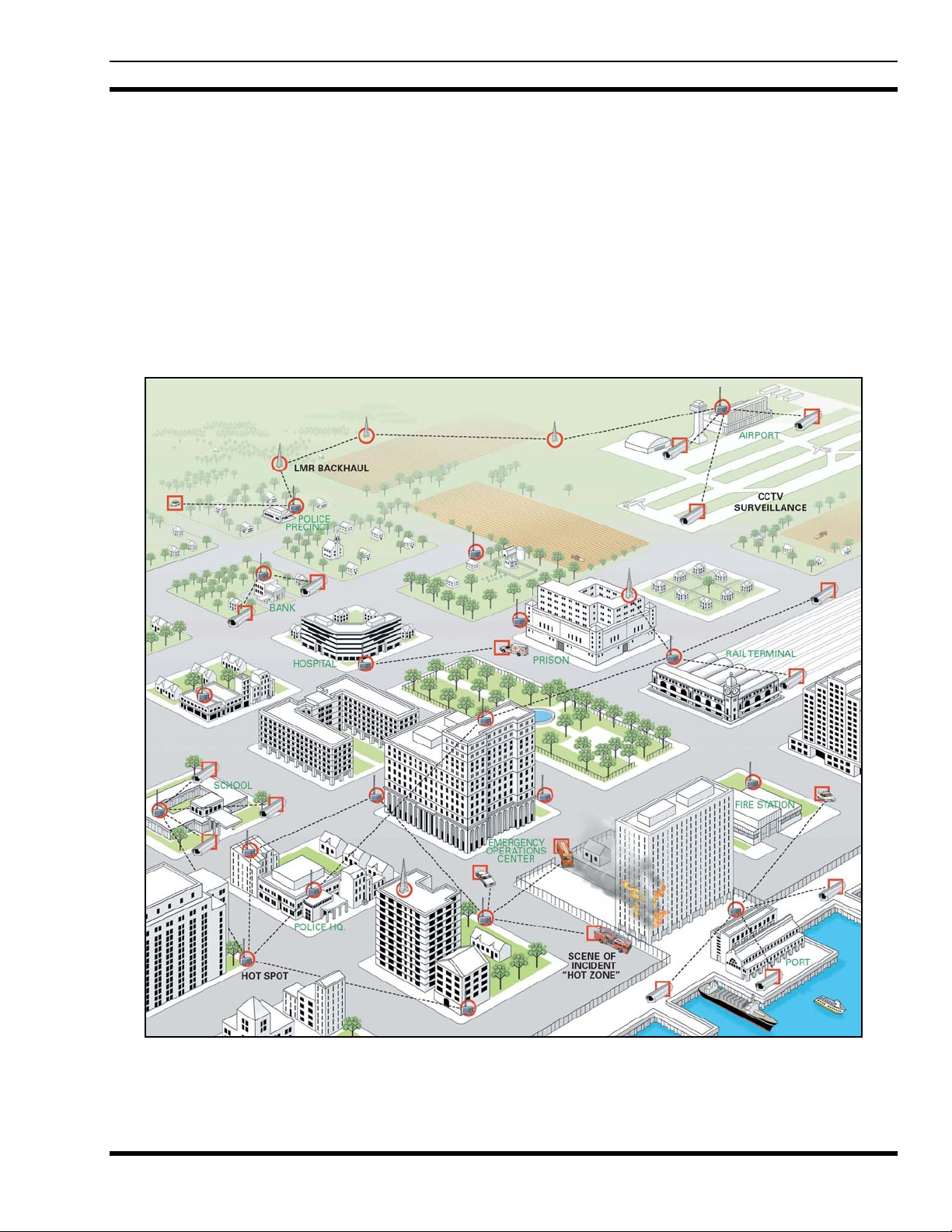
VIDA Broadband provides integrated public safety grade wireless broadband video and data services for
mission-critical applications. VIDA Broadband combines the security of the licensed 4.9 GHz public
safety frequency band with the robust 802.16 communications industry standard to create a true public
safety broadband network. With this state-of-the-art network, public safety customers can implement
applications such as streaming video, web applications, economical licensed LMR backhaul, and other
bandwidth intensive applications. Since the network provides guaranteed Quality of Service (QoS), it is
especially suited for applications such as video surveillance, perimeter control, and mobile command.
VIDA Broadband is integrated with the VIDA network allowing seamless sharing of network resources,
including hardware network management and administration.
MM-014720-001, Rev. A
Figure 2-1: VIDA Broadband Network
15

MM-014720-001, Rev. A
The basic architecture of the 4.9 GHz VIDA Broadband network is a point-to-multipoint network. A
system consists of one or more base station(s) and at least one or more clients per base station as shown in
Figure 2-1. There are two configurations of client
usually mounted outdoors with directional antennas and have a range of up to 10 miles. Nomadic clients
are vehicle mounted and use an omnidirectional antenna. The range of a nomadic client to base station is
typically a few hundred meters.
The VIDA Broadband Base Station implements the 802.16e-2005 OFDM protocol to deliver an over-theair throughput from 3 to 19 Mbps (for 5 MHz channel) and 38 Mbps (for 10 MHz channel). All
communication over the wireless channel is scheduled by the base station, with contention slots provided
for the VIDA Broadband Client to request bandwidth. This coordinated scheduling feature of the
protocol provides significant advantages such as:
• Minimizes contention between clients.
• Maximizes channel utilization.
• Maximizes ability to coordinate frequency usage among users.
• Enables guaranteed bandwidth services for critical applications.
devices; fixed and nomadic. Fixed client devices are
16

3. SYSTEM DESCRIPTION
VIDA Broadband provides a secure, mission critical grade point-multipoint wireless IP networking
solution. This system can be seen as providing a wireless extension of customers IP networks and can
support a wide variety of fixed and nomadic network applications such as IP surveillance video, secure
broadband backhaul, and nomadic network access. The base stations and clients in the VIDA Broadband
Network use IPC IP66-rated enclosures for operation in challenging environmental conditions, and the
UAS software is the same as that in use by numerous federal and public safety systems across North
America.
Both the VIDA Broadband Base Station and client are designed for easy mounting on a variety of outdoor
structures including light poles and telephone poles. The VIDA Broadband client can also be vehicle
mounted for nomadic applications using an optional vehicle mounting kit.
The VIDA Broadband system comprises the following:
• Base Station Equipment (BS): VIDA Broadband Base Stations provide the coordinating point
in a point-multipoint network, transferring data between an IP network and remote subscriber
stations as well as managing the subscriber stations on the network.
• Subscriber Station (SS): VIDA Broadband Client used to transfer data from a fixed or nomadic
location to the base station.
MM-014720-001, Rev. A
• MultiLink Station Equipment: VIDA Broadband MultiLink Stations provide full capacity
network extension, transferring data between an IP network and remote subscriber stations, with
no loss of capacity.
• Networking Equipment: Standard Switches and Routers supporting connections to the
backbone or Intranet.
• Management Systems: UAS Management, RNM system monitoring, and other Operation
Support Systems.
3.1 BASE STATION
The VIDA Broadband Base Station operates on a selected channel from eighteen possible 5 MHz
channels (10 Public Safety and 8 Federal) or nine possible 10 MHz channels (5 Public Safety and 4
Federal) of the IEEE 802.16e-OFDM profile in the 4.90 to 4.99 GHz communications band. The base
station transmits up to 27 dBm power and satisfies the high-power FCC mask. The Base Station is DC
powered and has the option of operating with either Copper Ethernet 100Base-TX or Fiber 100Base-FX.
The base stations are available in four configurations:
• MAVM-VMXBA (BS-009214-001) - AC powered with copper Ethernet (5 MHz)
• MAVM-VMXBC (BS-009214-003) - DC powered with copper Ethernet (w/surge protection)
(5MHz)
• MAVM-VMXBD (BS-009214-002) - DC powered with Fiber Optic Ethernet (w/surge
protection) (5MHz)
• MAVM-MBASE (BS-014648-004) - DC powered with Copper Ethernet and Fiber Optic ports
(5MHz/10MHz)
17
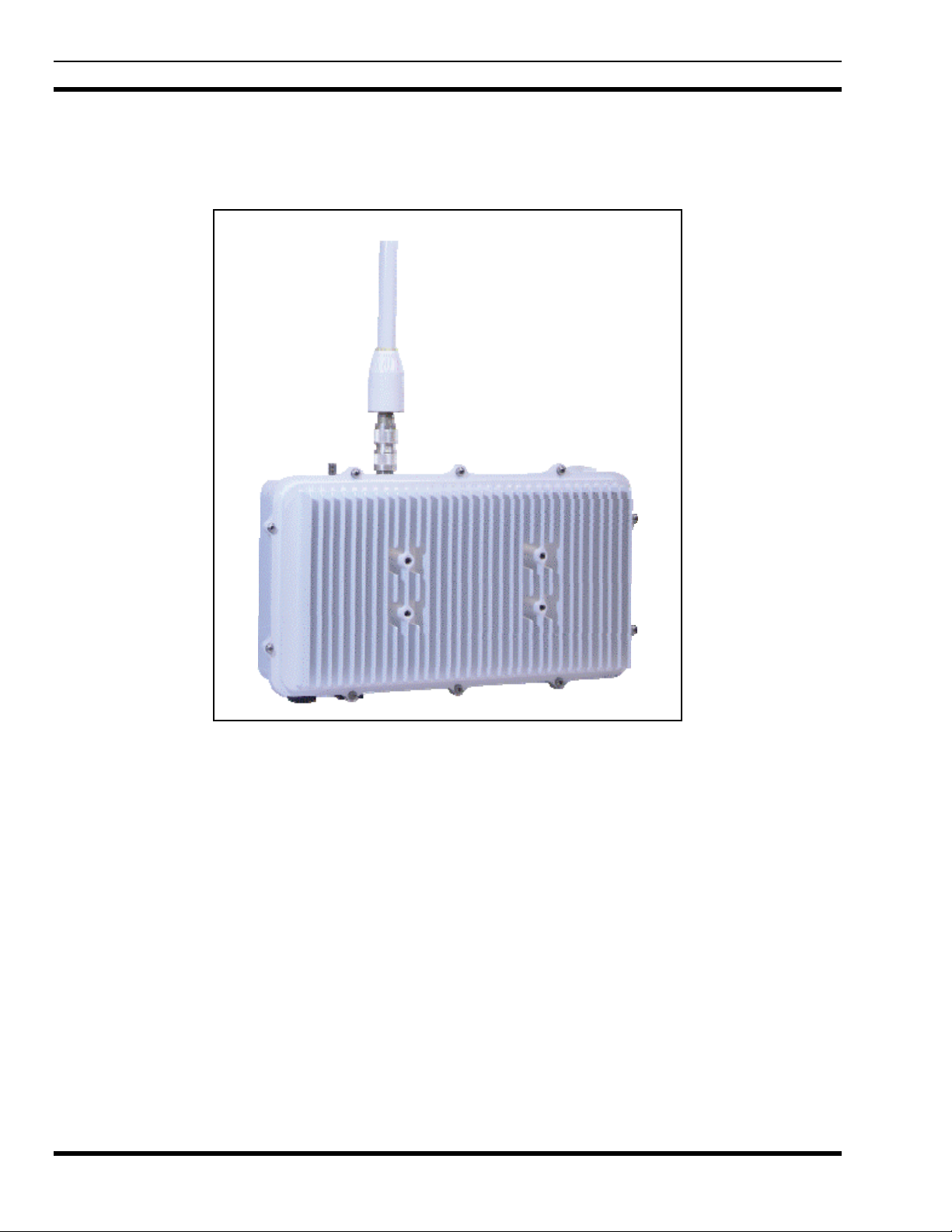
MM-014720-001, Rev. A
The AC model requires 110 Vac and uses a 100Base-TX Ethernet based data port configuration. The DC
models require +24 Vdc. The DC models have built-in surge protection and use either a 100Base-TX
Ethernet based data port configuration or a 100Base-FX Fiber Optic data port configuration. The
MAVM-MBASE model has both 100Base-TX and 100Base-FX ports.
18
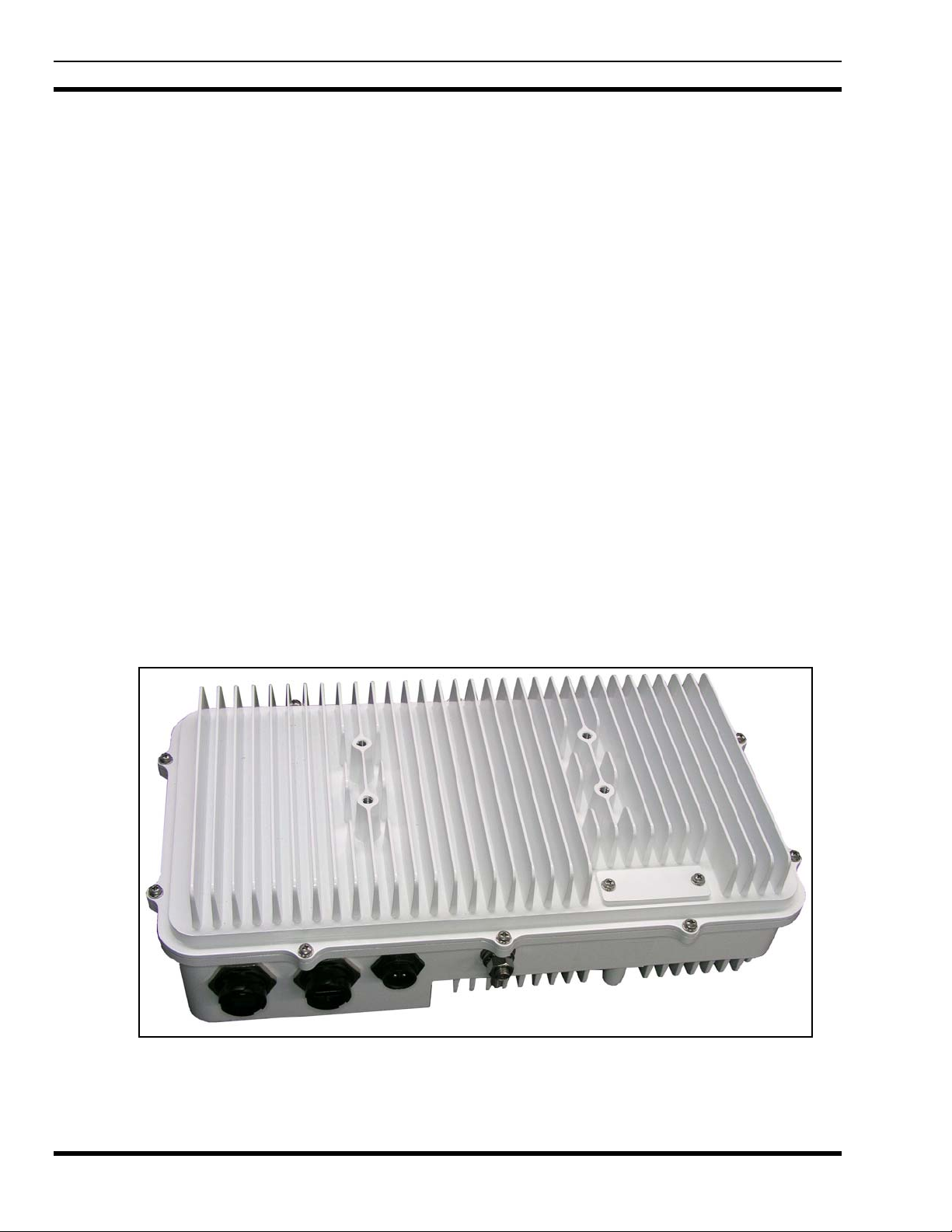
Figure 3-1: VIDA Broadband Base Station (BS-009214 model shown)
The VIDA Broadband Base Station is housed in a steel NEMA 4 enclosure that satisfies IP66
requirements for outdoor deployments. To provide for flexible RF deployment configurations, the base
station provides three antenna mounting options:
• Direct mounting of an omnidirectional antenna on the base station
• Direct mounting of a directional antenna on the front face of the base station, or
• Remote mounting of an antenna through the connection of an RF cable to the base station.
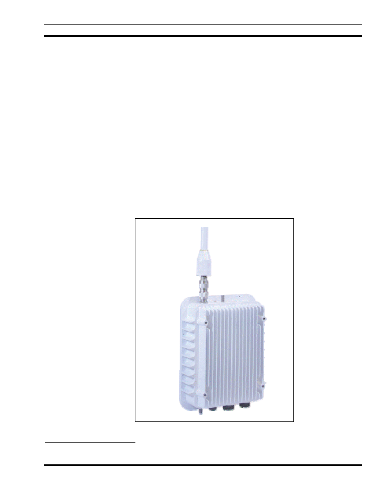
3.2 SUBSCRIBER STATION (CLIENT)
The VIDA Broadband Subscriber Station (SS), shown in Figure 3-2, is part of the VIDA Broadband
network. Subscriber stations, also referred to as clients, are available in five configurations:
• MAVM-VMCLL (BS-010700-001) - 4.9 GHz, 0.1W, Copper Ethernet
• MAVM-VMXCH (BS-010700-002) - 4.9 GHz, 0.5W, AC/DC, Copper Ethernet
• MAVM-VMCHN (BS-010700-002)
• MAVM-VMCHH (BS-010700-003) - 4.9 GHz, 0.5W, DC, Fiber (w/surge protection)
• MAVM-VMCLH (BS-010700-004) - 4.9 GHz, 0.1W, DC, Fiber (w/surge protection)
The high power (0.5 Watt) copper model is available as a fixed or nomadic application. The low power
(0.1 Watt) copper model is typically installed in fixed locations only. Both the high and low power
copper models are designed to operate on AC or DC voltage and use an Ethernet based data port
configuration.
The High and Low Power Standard models require 11 to 30 Vdc or 16 to 26 Vac. A DC supply is
recommended in all applications for cleaner and lower-noise power; however, an AC supply may be used.
The fiber models have built-in lightning protection, are powered by DC voltage only, and use a 100BaseFX Fiber Optic data port configuration.
1
- Nomadic 4.9 GHz, 0.5W, DC, Copper Ethernet
MM-014720-001, Rev. A
Figure 3-2: VIDA Broadband Client
1
High Power Copper Client supplied with nomadic installation kit.
19
MM-014720-001, Rev. A
The VIDA Broadband Client is housed in a steel NEMA 4 enclosure that satisfies IP66 requirements for
outdoor deployments. To provide for flexible RF deployment configurations, the client has three antenna
mounting options:
• Direct mounting of an omnidirectional antenna on the base station
• Direct mounting of a directional antenna on the front face of the base station, or
• Remote mounting of an antenna through the connection of an RF cable to the base station.
The VIDA Broadband Client provides public safety grade wireless connectivity for the 4.9 GHz VIDA
Broadband network. The VIDA Broadband Client provides public safety grade end-point connectivity for
the 4.9 GHz VIDA Broadband network.
3.3 MULTILINK STATION
The VIDA Broadband MultiLink Station’s base and subscriber functionality operate on separate single
channels selected from the eighteen possible 5 MHz channels (10 Public Safety and 8 Federal) or nine
possible 10 MHz channels (5 Public Safety and 4 Federal) of the IEEE 802.16e-OFDM profile in the 4.90
to 4.99 GHz communications band. The MultiLink Station transmits up to 27 dBm power out each
antenna port and both satisfy the high power FCC mask. The MultiLink Station is DC powered and has
the option of operating with either Copper Ethernet 100Base-TX and/or Fiber 100Base-FX. The
MultiLink Station merges the features of a base station with a fully functional subscriber with the same
outline and similar weight as a base station-only device. The base station and subscriber functions share
the 100- Base-TX Ethernet and 100-Base-FX fiber optic data ports through the internal Ethernet switch.
The MultiLink Station is ideal for full capacity network extension
The MultiLink Station, shown in Figure 3-3, is identified as follows:
• MAVM-MLINK (BS-014648-003) – M
Figure 3-3: VIDA Broadband MultiLink Station
ultiLink Station with Built-in Subscriber Station
20

The VIDA Broadband MultiLink Station is housed in a steel NEMA 4 enclosure that satisfies IP66
requirements for outdoor deployments. To provide for flexible RF deployment configurations, the base
station and built-in subscriber station can use a combination of antenna mounting options, including:
• Direct or remote mounting of an omnidirectional antenna on the base station or subscriber station
• Direct or remote mounting of a directional antenna on the front face of the MultiLink station for
either the base station or subscriber station, or
• Direct or remote mounting of an antenna through the connection of an RF cable to the base
station or subscriber station.
3.4 NETWORKING EQUIPMENT
The base station equipment is connected to the IP backbone through standard data communication and
telecommunication equipment. The 100Base-TX or 100Base-FX fiber ports of the base station can be
connected directly to a multi-port router or an Ethernet switch.
The point-to-point link from the base station to the backbone can be either wired or wireless. Data to the
Internet is routed to the backbone through standard routers.
The subscriber stations may also use their 100Base-TX or 100Base-FX fiber ports to connect directly to a
multi-port router or an Ethernet switch. Use of routers and switches depends on the site configuration
(point-to-point, multi-hop, backhaul, etc.) and associated equipment (cameras, cell site, etc.).
MM-014720-001, Rev. A
3.5 MANAGEMENT EQUIPMENT
Provisioning of the VIDA Broadband system is accomplished using the Unified Administration System
(UAS) installed on the Broadband Administration Server (BAS) or as part of the Regional VIDA
Manager (RVM) installed on a Sun Server.
For provisioning of a VIDA Broadband standalone system, the BAS is available in one of three
configurations. The BAS Laptop Server (CM-014992-003) configuration is useful when initial system
configuration is all that is required. For installations that may require frequent system changes or
adjustments, it is recommended to use the BAS Rack-mount Server (CM-014992-001) or the BAS Tower
Server (CM-014992-002).
For VIDA Broadband systems which are integrated with a radio communication system (P25, OpenSky,
etc.), the RVM UAS is required to configure/manage the broadband equipment from a centralized server.
3.5.1 Unified Administration System
The Unified Administration System (UAS) is the centralized access point from which the VIDA
Broadband network is provisioned. The network administrator uses the UAS to configure and provision
base stations, clients, service flows, and classifier rules to enable enforced QoS across the network.
Because VIDA Broadband uses the WiMAX scheduled protocol, the base stations are able to enforce
these rules over all traffic to provide guaranteed QoS. In addition, the network administrator can set up
and change mission-critical parameters (priorities, etc.) in real time to maximize performance during
specific incidents.
21
MM-014720-001, Rev. A
3.5.2 Regional Network Manager
The Regional Network Manager (RNM), part of the Regional VIDA Manager (RVM) on a Sun Unix
Server, provides system status, fault, and performance data. In addition, the RNM monitors system
activity in real time and logs all significant events.
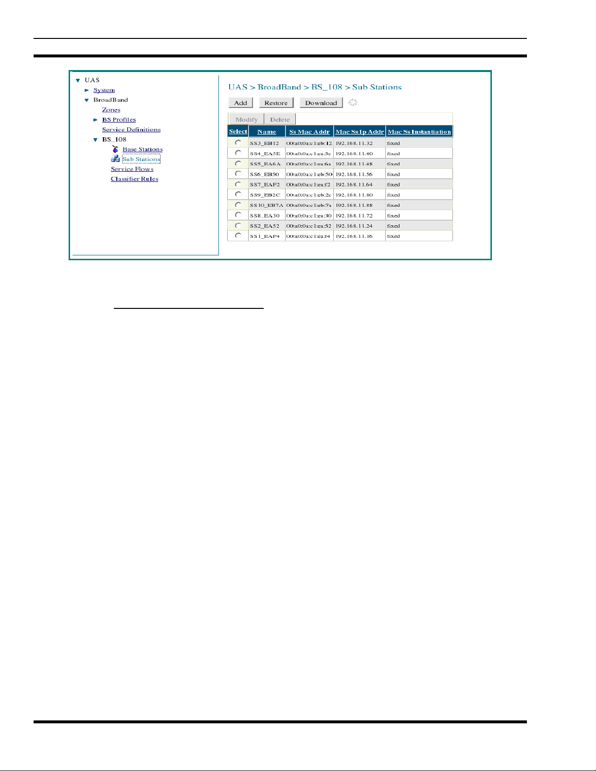
Figure 3-4: Example of UAS Subscriber Stations Screen
The RNM is a collection of applications and administrative programs that permit the user to view and
monitor the VIDA Broadband network components from a centralized access point. The RNM uses a
graphically oriented interface that creates a visual representation of the network.
A major feature of the RNM is the graphical visualizations of the VIDA Broadband network. For
example, the Network Viewer and Object List applications offer different representations of the
managed objects within the network (such as base stations, clients, routers, etc.). The Network Viewer
illustrates the hierarchical relationships, while the Object List allows you to specify powerful filtering
clauses. In both applications, the current status of each object is conveyed using descriptive color-coding.
The RNM also displays fault and performance information, allowing you to locate trouble spots in the
system and fix them quickly. It can also be set up to emit an audible alert when problems occur, thus
making it possible to quickly and effectively recover from problem situations.
22

MM-014720-001, Rev. A
4. PLANNING A FIXED STATION INSTALLATION
Careful planning and preparation of any installation will always benefit the end result. Follow these
simple recommendations when planning your installation:
1. Always read and follow all installation instructions, local and national building and electrical codes,
and general safety rules.
2. Before beginning the installation, collect information from the Site Deployment Order (SDO) specific
to the site access such as:
• Permission to access the site.
• Important contact names and telephone numbers.
• Location of and directions to the site.
• Keys and/or lock combinations to access the site and equipment shelter (if any), or points of
contact to obtain them.
• Site entry alarm system pass-codes and/or disable keys.
• Information about work practices needed to work safely at the site.
3. Other important information that may or may not be included on the SDO includes:
• Type of mounting—metal pole, wooden pole, tower base, exterior wall, etc.
• Drawing or description of each site showing how the equipment is to be installed.
• Applicable inspections completed (pole installation, electrical, local build code, etc.).
• Installer must be aware of other transmitters and receivers on site that could cause interference to,
or be interfered with by, the broadband equipment. Strong signals from, or to, co-located
equipment may inflict permanent damage to either device.
VIDA Broadband equipment has a maximum allowed input power of 0 dBm in the 4.9
to 4.99 GHz band. Although other frequencies may have a higher threshold, any
signal, at any frequency, above 0 dBm presented to the Broadband equipment should
be cleared by the factory prior to installation.
4. We recommend pre-staging the equipment to become familiar with the specific hardware and cabling,
tooling, and supplies that are needed to complete the installation.
4.1 SITE EVALUATION
Before installing the VIDA Broadband Client, the System Engineer and Installer should plan the site
installation. Since higher RF frequencies do not readily pass through trees or buildings, consideration
should be given to the following:
• Ensure there are no obstructions (such as buildings or trees) in the radio path between base station
and client units.
• Ensure that any future building construction or tree growth will not obstruct the radio path.
23
 Loading...