

Page 1
VCA/VDA/VEA6800+
Analog Video Distribution Amplifiers
Installation and Operation Manual
Edition D
175-000181-00
Page 2

Page 3

Preliminary—Contents are proprietary and confidential. Do not photocopy or distribute.
VCA 6800+
VDA6800+
VEA6800+
Analog Video Distribution
Amplifier
Installation and Operation
Manual
Edition D
July 2007
Page 4

Preliminary—Contents are proprietary and confidential. Do not photocopy or distribute.
Copyright Information
Copyright 2007 Harris Corporation, 1025 West NASA Boulevard,
Melbourne, Florida 32919-0001 U.S.A. All rights reserved. This
publication supersedes all previous releases. Printed in Canada.
This product and related documentation are protected by copyright and
are distributed under licenses restricting their use, copying, distribution,
and decompilation. No part of this product or related documentation
may be reproduced in any form by any means without prior written
authorization of Harris Corporation and its licensors, if any.
This publication could include technical inaccuracies or typographical
errors. Changes are periodically added to the information herein; these
changes will be incorporated into new editions of the publication.
Harris Corporation may make improvements and/or changes in the
product(s) and/or the program(s) described in this publication at any
time.
Warranty Information
The Limited Warranty Policy provides a complete description of your
warranty coverage, limitations, and exclusions, as well as procedures
for obtaining warranty service. To view the complete warranty, visit our
website.
Page 5

Preliminary—Contents are proprietary and confidential. Do not photocopy or distribute.
Contents
Preface
Manual Information .............................................................................. vii
Purpose ........................................................................................... vii
Audience ........................................................................................ vii
Revision History ............................................................................ vii
Writing Conventions ..................................................................... viii
Obtaining Documents ................................................................... viii
Unpac king / Ship ping Inf ormation .......... .......... .......... ......... .......... ......... ix
Safety Standards and Compliances ..........................................................x
Safety Terms and Symbols ...............................................................x
Restriction on Hazardous Substances (RoHS) Directive ................ xi
Waste from Electrical and Electronic Equipment
(WEEE) Directive .......................................................................... xii
Chapter 1: Introduction
Overview ...................................................................................................1
Product Description ..................................................................................2
Typical Broadcast and Production Applications ..............................2
Main Features ...................................................................................2
Module Descriptions ................................................................................5
Front Module ....................................................................................5
Back Modules ...................................................................................9
Block Diagrams ......................................................................................11
Chapter 2: Installation and Configuration
Overview .................................................................................................13
Maximum 6800+ Frame Power Ratings ................................................14
VCA / VDA / VEA6800+ Installation and Operation Manual v
Page 6

Preliminary—Contents are proprietary and confidential. Do not photocopy or distribute.
Contents
Unpacking the Module .......................................................................... 15
Preparing the Product for Installation ............................................ 15
Checking the Packing List ............................................................. 15
Setting Jumpers and Adjustable Components ....................................... 17
VCA6800+ ..................................................................................... 17
VDA6800+ .................................................................................... 20
VEA6800+ ..................................................................................... 22
Installing 6800+ Modules ..................................................................... 24
Required Frames and Back Connector Types ................................ 24
Installing VCA/VDA/VEA6800+ Modules .................................. 24
Removing VCA/VDA/VEA6800+ Modules ................................. 24
Making Connections ...................................................................... 24
Chapter 3: Specifications
Overview ................................................................................................ 25
Inputs ..................................................................................................... 26
Outputs .................................................................................................. 28
Performance .......................................................................................... 29
Propagation Delay ................................................................................. 32
Temperature ........................................................................................... 32
Index
Keywords .............................................................................................. 33
vi VCA / VDA / VEA6800+ Installation and Operation Manual
Page 7
Preliminary—Contents are proprietary and confidential. Do not photocopy or distribute.
Preface
Manual Information
Purpose
This manual details the features, installation procedures, operational
procedures, and specifications of the VCA / VDA / VEA6800+ analog
video distribution amplifiers.
Audience
This manual is written for engineers, technicians and operators
responsible for the installation, setup, and / or operation of the
VCA / VDA / VEA6800+ analog video distribution amplifiers.
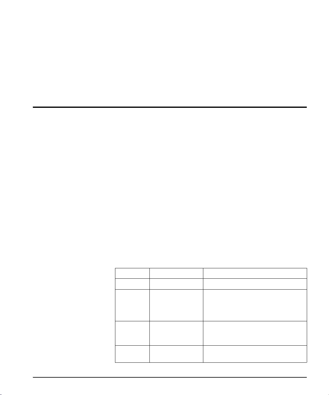
Revision History
Table P-1. Manual Revision History
Edition Date Revision History
A December 2003 Initial release
B June 2004
C August 2005
D July 2007
VCA / VDA / VEA6800+ Installation and Operation Manual vii
• Added information about maximum
6800+ frame power ratings
• Added information concerning
looping input termination
• Added list of equalization cable types
for VEA6800+
• Added index
• Updated input specifications
• Updated frame power ratings
Page 8
Preliminary—Contents are proprietary and confidential. Do not photocopy or distribute.
Preface
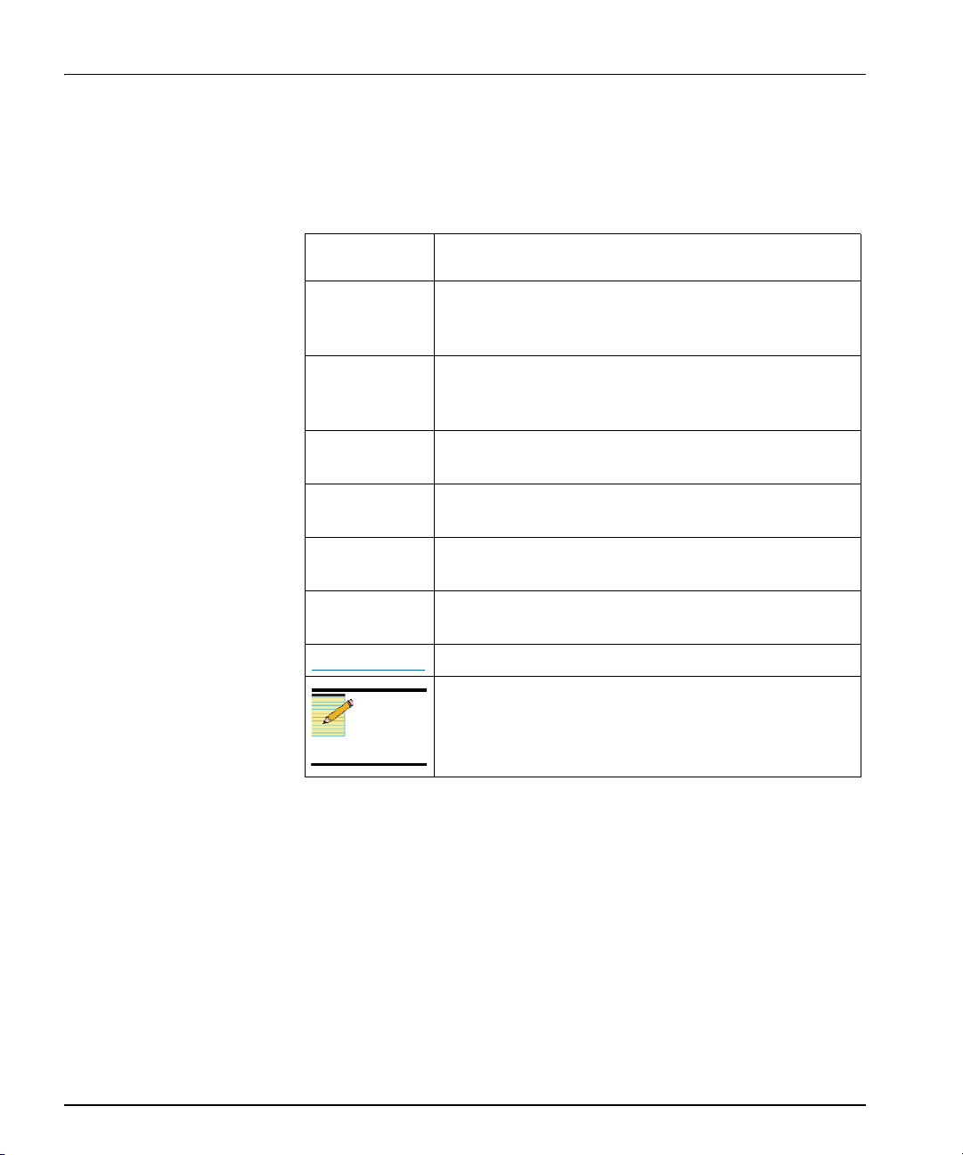
Writing Conventions
To enhance your understanding, the authors of this manual have
adhered to the following text conventions:
Table P-2. Manual Style and Writing Conventions
Term or
Convention
Bold Indicates dialog boxes, property sheets, fields, buttons,
Italics Indicates email addresses, the names of books or
CAPS Indicates a specific key on the keyboard, such as ENTER,
Description
check boxes, list boxes, combo boxes, menus, submenus,
windows, lists, and selection names.
publications, and the first instances of new terms and
specialized words that need emphasis.
TAB, CTRL, ALT, or DELETE.
Code Indicates variables or command-line entries, such as a
DOS entry or something you type into a field.
> Indicates the direction of navigation through a hierarchy
of menus and windows.
hyperlink Indicates a jump to another location within the electronic
document or elsewhere
Internet address
Note
Indicates a jump to a Web site or URL
Indicates important information that helps to avoid and
troubleshoot problems.
Obtaining Documents
Technical documents can be viewed or downloaded from our website.
Alternatively, contact your Customer Service representative to request a
document.
viii VCA / V DA / VEA 6800 + Installation and Operation Manual
Page 9

Preliminary—Contents are proprietary and confidential. Do not photocopy or distribute.
Preface
Unpacking / Shipping Information
This product was carefully inspected, tested, and calibrated before
shipment to ensure years of stable and trouble free service.
1. Check equipment for any visible damage that may have occurred
during transit.
2. Confirm that you have received all items listed on the packing list.
3. Contact your dealer if any item on the packing list is missing.
4. Contact the carrier if any item is damaged.
5. Remove all packaging material from the product and its associated
components before you install the unit.
Keep at least one set of original packaging, in the event that you need to
return a product for servicing. If the original packaging is not available,
you can purchase replacement packaging at a modest cost or supply
your own packaging as long as it meets the following criteria:
• Withstands the weight of the product
• Holds the product rigid within the packaging
• Leaves at least two inches of space between the product and the
container
• Protects the corners of the product
Ship products back to us for servicing prepaid and, if possible, in the
original packaging material. If the product is still within the warranty
period, we will return the product prepaid after servicing.
VCA / VDA / VEA6800+ Installation and Operation Manual ix
Page 10
Preliminary—Contents are proprietary and confidential. Do not photocopy or distribute.
Preface
Safety Standards and Compliances
See the 6800+ Safety Instructions and Standards Manual to find the
safety standards and compliances for this 6800+ series product. A
safety manual is shipped with every FR6802+ Frame Installation and
Operation Manual and can be downloaded from our website.
Alternatively, contact your Customer Service representative for a copy
of this safety manual.
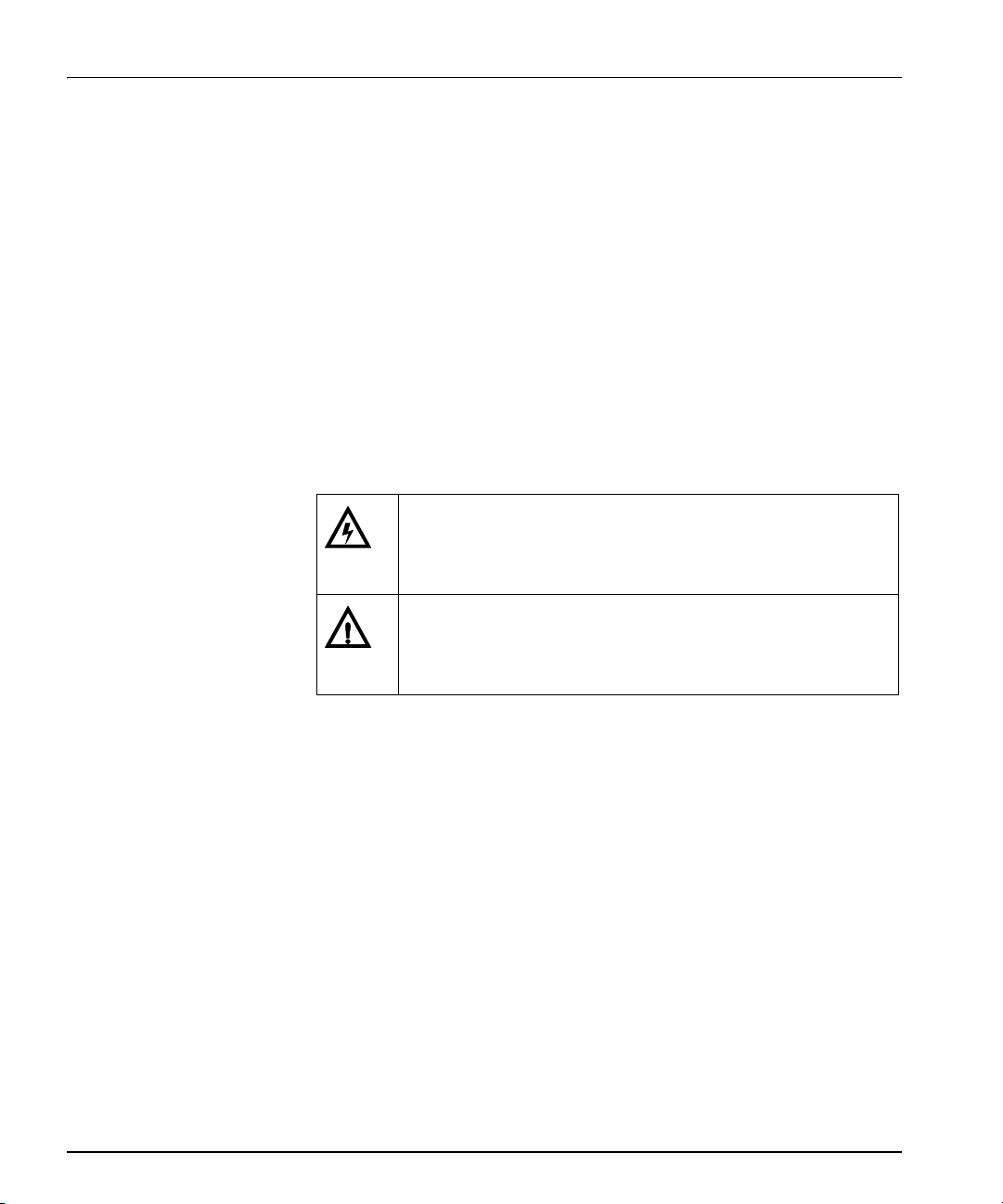
Safety Terms and Symbols
This product manual uses the following safety terms and symbols to
identify certain conditions or practices. See the 6800+ Safety
Instructions and Standards Manual for more information.
Table P-3. Safety Terms and Symbols
WARNING: Identifies conditions or practices that can result in
personal injury or loss of life—high voltage is present.
Uninsulated dangerous voltage within the product’s enclosure
may be sufficient to constitute a risk of electric shock to persons.
CAUTION: Identifies conditions or practices that can result in
damage to the equipment or other property. Important operating
and maintenance (servicing) instructions are included in the
literature accompanying the product.
x VCA / VDA / VEA6800+ Installation and Operation Manual
Page 11

Preliminary—Contents are proprietary and confidential. Do not photocopy or distribute.
Preface
Restriction on Hazardous Substances (RoHS) Directive
Directive 2002/95/EC—commonly known as the European Union (EU)
Restriction on Hazardous Substances (RoHS)—sets limits on the use of
certain substances found in electrical and electronic equipment. The
intent of this legislation is to reduce the amount of hazardous chemicals
that may leach out of landfill sites or otherwise contaminate the
environment during end-of-life recycling. The Directive, which took
effect on July 1, 2006, refers to the following hazardous substances:
• Lead (Pb)
• Mercury (Hg)
• Cadmium (Cd)
• Hexavalent Chromium (Cr-V1)
• Polybrominated Biphenyls (PBB)
• Polybrominated Diphenyl Ethers (PBDE)
According to this EU Directive, all products sold in the European Union
will be fully RoHS-compliant and “lead-free.” (See our website for
more information on dates and deadlines for compliance.) Spare parts
supplied for the repair and upgrade of equipment sold before
July 1, 2006 are exempt from the legislation. Equipment that complies
with the EU directive will be marked with a RoHS-compliant emblem,
as shown in Figure P-1.
Figure P-1. RoHS Compliance Emblem
VCA / VDA / VEA6800+ Installation and Operation Manual xi
Page 12
Preliminary—Contents are proprietary and confidential. Do not photocopy or distribute.
Preface
Waste from Electrical and Electronic Equipment (WEEE) Directive
The European Union (EU) Directive 2002/96/EC on Waste from
Electrical and Electronic Equipment (WEEE) deals with the collection,
treatment, recovery, and recycling of electrical and electronic waste
products. The objective of the WEEE Directive is to assign the
responsibility for the disposal of associated hazardous waste to either
the producers or users of these products. As of August 13, 2005,
producers or users are required to recycle electrical and electronic
equipment at end of its useful life, and may not dispose of the
equipment in landfills or by using other unapproved methods. (Some
EU member states may have different deadlines.)
In accordance with this EU Directive, companies selling electric or
electronic devices in the EU will affix labels indicating that such products must be properly recycled. (See our website for more information
on dates and deadlines for compliance.) Contact your local sales representative for information on returning these products for recycling.
Equipment that complies with the EU directive will be marked with a
WEEE-compliant emblem, as shown in Figure P-2.
Figure P-2. WEEE Compliance Emblem
xii VCA / VDA / VEA6800+ Installation and Operation Manual
Page 13

Preliminary—Contents are proprietary and confidential. Do not photocopy or distribute.
Chapter 1
Introduction
Overview
This chapter introduces the VCA / VDA / VEA6800+, and includes the
following topics:
The following topics are described in this chapter:
• “Block Diagrams” on page 11
• “Main Features” on page 2
• “Module Descriptions” on page 5
• “Product Description” on page 2
VCA / VDA / VEA6800+ Installation and Operation Manual 1
Page 14

Preliminary—Contents are proprietary and confidential. Do not photocopy or distribute.
Chapter 1: Introduction
Product Description
The VCA / VDA / VEA6800+ is an analog video distribution amplifier
set in the new 6800+ family.
These DAs feature high video performance, low cost, and remote
control.
Typical Broadcast and Production Applications
The VCA / VDA / VEA6800+ distribution amplifier can be used in
broadcast, cable, production, educational, and auditorium applications
where a low cost method of distributing analog video signals is
required.
Main Features
VCA6800+
The VCA6800+ is an analog video clamping and equalizing
distribution amplifier. Other VCA6800+ features include the following:
• One differential input
• Eight outputs with dual slots back module, four outputs with single
slot back module when installed in FR6802+X(F) frames; eight
outputs when installed in FR6802+DM(F) frames
• AC and DC input coupling selectable
• Looping and internal terminating selectable with dual slot back
module, internal terminating with single slot back module with
FR6802+X(F) frames; looping or internal terminating selectable
with FR6802+DM(F) frames (see Figure 2-2 on page 18 for
instructions on setting this jumper)
• ± 3 dB gain adjustable range
• >50 MHz bandwidth
• Continuous cable equalizing up to 984 ft (300 m) Belden 8281
cable, or equivalent
• Back porch clamp with selectable soft, hard and non-clamp modes
Gain and EQ setting components are installed on a removable
submodule; in the event of failure on the DA module, a replacement
can be quickly inserted with the original submodule to keep the
previous setting
2 VCA / VDA / VEA6800+ Installation and Operation Manual
Page 15

Preliminary—Contents are proprietary and confidential. Do not photocopy or distribute.
Chapter 1: Introduction
• Module presence reporting via +Pilot Lite control system
• Hot swappable
VDA6800+
The VDA6800+ is a high performance, cost efficient, general purpose
analog video distribution amplifier. Composite and component analog
NTSC, PAL, SECAM signals (with sync or without sync), subcarrier,
and coaxial version AES digital audio signals can be amplified with the
VDA6800+ in FR6802+ series frames. Other VDA6800+ features
include the following:
• One differential input
• Eight outputs with dual slots back module, four outputs with single
slot back module when installed in FR6802+X(F) frames; eight
outputs when installed in FR6802+DM(F) frames
• DC input coupling
• Looping and internal terminating selectable with dual slot back
module, internal terminating with single slot back module with
FR6802+X(F) frames; looping or internal terminating selectable
with FR6802+DM(F) frames (see Figure 2-7 on page 21 for
instructions on setting this jumper)
• ± 3dB gain adjustable range
• > 50 MHz bandwidth
• Module presence reporting via +Pilot Lite control system
• Hot swappable
VEA6800+
The VEA6800+ is a high performance analog video equalizing
distribution amplifier. Composite and component analog NTSC, PAL,
SECAM signals, with or without sync, and subcarrier signal can be
amplified with VEA6800+ in FR6802+ series frames. Other
VEA6800+ features include the following:
• One differential input
• Eight outputs with dual slots back module, four outputs with single
slot back module when installed in FR6802+X(F) frames; eight
outputs when installed in FR6802+DM(F) frames
• DC input coupling
VCA / VDA / VEA6800+ Installation and Operation Manual 3
Page 16

Preliminary—Contents are proprietary and confidential. Do not photocopy or distribute.
Chapter 1: Introduction
• Looping and internal terminating selectable with dual slot back
module, internal terminating with single slot back module with
FR6802+X(F) frames; looping or internal terminating selectable
with FR6802+DM(F) frames (see Figure 2-10 on page 22 for
instructions on setting this jumper)
• ± 3 dB gain adjustable range
• > 50 MHz bandwidth
• Continuous cable equalizing up to 984 ft (300 m) Belden 8281
cable, or equivalent
• Gain and EQ setting components are installed on a removable
submodule; in the event of failure on the DA module, a replacement
DA module can be quickly inserted with the original submodule to
keep the previous setting
• Optional equalizers for different cable types
• Module presence reporting via +Pilot Lite control system
• Hot swappable
4 VCA / VDA / VEA6800+ Installation and Operation Manual
Page 17

Preliminary—Contents are proprietary and confidential. Do not photocopy or distribute.
Chapter 1: Introduction
Module Descriptions
Front Module
VCA6800+
Figure 1-1 is a generic top-front view of a typical VCA6800+ front
module. See Figure 2-1 on page 17 for jumper and adjustment
locations.
Figure 1-1. Typical VCA6800+ Front Module
VDA6800+
Figure 1-2 is a generic top-front view of a typical VDA6800+ front
module. See Figure 2-6 on page 20 for jumper and adjustment
locations.
Figure 1-2. Typical VDA6 80 0+ Front Module
VCA / VDA / VEA6800+ Installation and Operation Manual 5
Page 18

Preliminary—Contents are proprietary and confidential. Do not photocopy or distribute.
Chapter 1: Introduction
VEA6800+
Figure 1-3 is a generic top-front view of a typical VEA6800+ front
module. See Figure 2-9 on page 22 for jumper and adjustment
locations.
Figure 1-3. Typical VEA6800+ Front Module
The VEA6800+ can compensate for various cable types using different
equalization network submodules installed in the main module.The
following modules are available:
Table 1-1. Product Equalization Cable Types
Product Equalization Cable Type
VEA6800+(S,D) Equalizing video distribution amplifier for 1000 ft
(300 m) Belden 8281 cable
VEA6800+(S,D)-1 Equalizing video distribution amplifier for 650 ft
(200 m) Belden 8241 cable
VEA6800+(S,D)-2 Equalizing video distribution amplifier for 800 ft
(250 m) Belden 1505A cable
VEA6800+(S,D)-3 Equalizing video distribution amplifier for 1000 ft
(300 m) Belden 1694A cable
VEA6800+(S,D)-4 Equalizing video distribution amplifier for 650 ft
(200 m) PSF 1/3 cable
6 VCA / VDA / VEA6800+ Installation and Operation Manual
Page 19

Preliminary—Contents are proprietary and confidential. Do not photocopy or distribute.
Chapter 1: Introduction
LEDs, Switches, and Jumpers
Table 1-2 briefly describes generic 6800+ LEDs, switches, and
jumpers. See Chapter 2: “Installation and Configuration” for more
information on specific VCA / VDA / VEA6800+ module controls,
LEDs, and jumpers.
Table 1-2. Generic 6800+ Module Features
Feature Description
Module status
LEDs
Control LEDs Various lighting combinations of these control LEDs
Monitoring
LEDs
Local/remote
control jumper
Various color and lighting combinations of these LEDs
indicate the module state. See Table 1-3 for more
information.
(sometimes referred to as “Bank Select LEDs”) indicate
the currently selected bank. (This item not available on
the VCA / VDA / VEA6800+)
Each 6800+ module has a number of LEDs assigned to
indicate varying states/functions.
• Local: Locks out external control panels and allows
card-edge control only; limits the functionality of
remote software applications to monitoring
• Remote: Allows remote or local (card-edge)
configuration, operation, and monitoring of the
VCA / VDA / VEA6800+
Each 6800+ module has a number of LEDs assigned to indicated
varying states/functions. These functions are listed in Table 1-3.
Table 1-3. VCA / VDA / VEA6800+ Module-Specific Status LEDs
Condition Color Function
All OK
No Errors
Green No error, everything working well
No lock Red Signal not present or cannot be locked
Biphase
coding error
Parity error Amber AES stream’s parity not set as specified
CRC error Amber CRC value calculated for incoming data
VCA / VDA / VEA6800+ Installation and Operation Manual 7
Amber Biphase coding of incoming data incorrect
does not match the CRC byte of channel
status word
Page 20

Preliminary—Contents are proprietary and confidential. Do not photocopy or distribute.
Chapter 1: Introduction
Table 1-3. VCA / VDA / VEA6800+ Module-Specific Status LEDs
Condition Color Function
Confidence
flag error
Amber Received data eye opening less than half a
bit period, indicating a possible lack of
signal strength or high jitter; also may mean
that insufficient EQ applied
Validity error Amber AES stream’s validity bit is high (incoming
data not suitable for conversion to an analog
audio signal)
Alarm Amber External alarm contact closure asserted; card
reporting an alarm
Frame status* Red Frame alarm
Green All OK, no frame alarm
* If the frame status LED is not lit, the module may not be operational.
8 VCA / VDA / VEA6800+ Installation and Operation Manual
Page 21

Preliminary—Contents are proprietary and confidential. Do not photocopy or distribute.
Chapter 1: Introduction
Back Modules
FR6802+ Frame Back Module
Figure 1-4 shows the single-width back connector module and
Figure 1-5 shows the double-slot back connector module used by the
VCA / VDA / VEA6800+ when installed in an FR6802+ frame.
Figure 1-4. Single-Width Back Modules for FR6802+ Frame
Figure 1-5. Double-Width Back Module for FR6802+ Frame
VCA / VDA / VEA6800+ Installation and Operation Manual 9
Page 22

Preliminary—Contents are proprietary and confidential. Do not photocopy or distribute.
Chapter 1: Introduction
Signal Input/Output Connections for FR6802+DM Frames
Figure 1-6 shows the signal input/output connections used by the
Note
In a DM frame, you can create
looping inputs by adding a
T-connector on the input
connection and changing the
input termination mode jumper
setting to external termination.
(The internal termination setting
is used for non-looping inputs.)
VCA / VDA / VEA6800+ when installed in an FR6802+DM frame.
Figure 1-6. Double-Width Back Module for FR6802+DM Frames
6800/ 7000 Series Frame Back Module (Overlay)
Figure 1-7 shows the double-slot back connector overlay used by a
Note
Remote monitoring for the
VCA / VDA / VEA6800+
module is not available if it is
installed in a 6800/7000 series
frame.
VCA / VDA / VEA6800+ module when installed in a 6800 / 7000 series
frame.
Figure 1-7. Back Connector for 6800 / 7000 Series Frame
10 VCA / VDA / VEA6800+ Installation and Operation Manual
Page 23

Preliminary—Contents are proprietary and confidential. Do not photocopy or distribute.
Chapter 1: Introduction
Block Diagrams
AC
Input
Te rm ination
select
DC
AC
DC
differential
amplifier
Cable equalizer
Gain
EQ
Clamp
Clamp mode
select
Output
driver
Figure 1-8. VCA6800+ Block Diagram
Figure 1-9. VDA6800+ Block Diagram
No clamp
Soft clamp
Hard clamp
VCA / VDA / VEA6800+ Installation and Operation Manual 11
Page 24

Preliminary—Contents are proprietary and confidential. Do not photocopy or distribute.
Chapter 1: Introduction
Figure 1-10. VEA6800+ Block Diagram
12 VCA / VDA / VEA6800+ Installation and Operation Manual
Page 25

Preliminary—Contents are proprietary and confidential. Do not photocopy or distribute.
Chapter 2
Installation and Configuration
Overview
This chapter describes the VCA / VDA / VEA6800+ installation process,
Caution
Before installing this product,
read the 6800+ Series Safety
Instructions and Standards
manual shipped with every
FR6802+ Frame Installation
and Operation Manual, or
downloadable from our website.
This safety manual contains
important information about the
safe installation and operation
of 6800+ series products.
Before installing this product,
see “Unpacking the Module” on
page 15.
including the following topics:
• “Maximum 6800+ Frame Power Ratings” on page 14
• “Unpacking the Module” on page 15
• “Setting Jumpers and Adjustable Components” on page 17
• “Installing 6800+ Modules” on page 24
• “Making Connections” on page 24
See the FR6802+ Frame Installation and Operation Manual for
information about installing and operating an FR6802+ frame and its
components.
This chapter also describes how to operate the VCA / VDA / VEA6800+
for use with local controls only. See the following documents for
information on how to operate this product remotely:
• +Pilot Lite User Manual for serial control interface
• CCS™ Navigator™, Pilot™, CoPilot™, or RCP-CCS-1U Remote
Control Panel Installation and Operation Manual for Ethernet
control interface
VCA/VDA/VEA6800+ Installation and Operation Manual 13
Page 26

Preliminary—Contents are propriet ary and confidential. Do not photocopy or distribute.
Chapter 2: Installation and Configuration
Maximum 6800+ Frame Power Ratings
Table 2-1 describes the maximum allowable power ratings for 6800+
frames.Note the given maximums before installing a ny 6800+ modules
in your frame.
VCA/VDA/VEA6800+ modules can be installed in FR6802+ frames
and 6000/7000 series frames.
Table 2-1. Maximum Power Ratings for 6800+ Frames
6800+ Frame Type
FR6802+XF
(frame with AC power
supply)
FR6802+XF48
(frame with DC power
supply)
Max. Frame
Power
Dissipation
120 W 20 6 W
105 W 20 5.25 W
Number of
Usable Slots
Max. Power
Dissipation Per
Slot
14 VCA/VDA/VEA6800+ Installation and Operation Manual
Page 27

Preliminary—Contents are proprietary and confidential. Do not photocopy or distribute.
Chapter 2: Installation and Configuration
Unpacking the Module
Preparing the Product for Installation
Before you install the VCA/VDA/VEA6800+, perform the following:
Note
Contact your customer service
representative if parts are
missing or damaged.
Checking the Packing List
• Check the equipment for any visible damage that may have
occurred during transit.
• Confirm receipt of all items on the packing list. See “Checking the
Packing List” for more information.
• Remove the anti-static shipping pouch, if present, and all other
packaging material.
• Retain the original packaging materials for possible re-use.
See “Unpacking / Shipping Information” on page ix for information
about returning a product for servicing.
Table 2-2. VCA/VDA/VEA6800+ Packing List
Ordered Product Content Description
VCA6800+
VCA6800+
VCA6800+S
VCA6800+D
VCA6800+SR
VCA6800+DR
VDA6800+
VDA6800+
• One VCA6800+ front module
•One V CA / VDA / VEA6800+ Installation and
Operation Manual
• One VCA6800+ front module
• One standard single-slot back connector
•One V CA / VDA / VEA6800+ Installation and
Operation Manual
• One VCA6800+ front module
• One standard double-slot back connector
•One V CA / VDA / VEA6800+ Installation and
Operation Manual
• One standard single-slot back connector
• One standard double-slot back connector
• One VDA6800+ front module
•One V CA / VDA / VEA6800+ Installation and
Operation Manual
VCA/VDA/VEA6800+ Installation and Operation Manual 15
Page 28

Preliminary—Contents are proprietary and confidential. Do not photocopy or distribute.
Chapter 2: Installation and Configuration
Table 2-2. VCA/VDA/VEA6800+ Packing List (Continued)
Ordered Product Content Description
VDA6800+S
VDA6800+D
• One VDA6800+ front module
• One standard single-slot back connector
•One V CA / VDA / VEA6800+ Installation and
Operation Manual
• One VDA6800+ front module
• One standard double-slot back connector
•One V CA / VDA / VEA6800+ Installation and
Operation Manual
VDA6800+SR
VDA6800+DR
VEA6800+
VEA6800+
VEA6800+S
VEA6800+D
VEA6800+SR
VEA6800+DR
• One standard single-slot back connector
• One standard double-slot back connector
• One VEA6800+ front module
•One V CA / VDA / VEA6800+ Installation and
Operation Manual
• One VEA6800+ front module
• One standard single-slot back connector
•One V CA / VDA / VEA6800+ Installation and
Operation Manual
• One VEA6800+ front module
• One standard double-slot back connector
•One V CA / VDA / VEA6800+ Installation and
Operation Manual
• One standard single-slot back connector
• One standard double-slot back connector
16 VCA/VDA/VEA6800+ Installation and Operation Manual
Page 29

Preliminary—Contents are proprietary and confidential. Do not photocopy or distribute.
Chapter 2: Installation and Configuration
Setting Jumpers and Adjustable Components
VCA6800+
The VCA6800+ module has four jumpers, which are used to select the
following modes:
• One jumper for looping or internal input termination
• Two jumpers for AC or DC coupling mode
• One jumper for soft-, hard-, or no-clamping mode
The VCA6800+ module also has adjustable potentiometers (“pots”) for
Gain and EQ modes.
Figure 2-1. Location of the VCA6800+ Jumper Blocks and Adjustable Pots
VCA/VDA/VEA6800+ Installation and Operation Manual 17
Page 30

Preliminary—Contents are proprietary and confidential. Do not photocopy or distribute.
AC mode
C mode
Chapter 2: Installation and Configuration
Setting the Input Terminating Jumper
Follow this procedure to set the jumper for looping or internal input
Note
In a DM frame, you can create
looping inputs by adding a
T-connector on the input
connection and changing the
input termination mode jumper
setting to external termination.
(The internal termination setting
is used for non-looping inputs.)
For BMFL modules, the input
termination jumper default
mode is for external
termination. This is the setting
you will need if you are using a
looping input.
termination:
1. Locate the jumper block on the module. Figure 2-1 on page 17
shows the location of this jumper block.
2. Place the jumper on the pin that corresponds to looping or internal
input termination. See Figure 2-2.
Figure 2-2. VCA6800+ Input Terminating Jumper Block Pin
Placement
Setting the Coupling Mode
Follow this procedure to set the jumper for AC or DC coupling mode:
1. Locate the jumper block on the module. Figure 2-1 on page 17
shows the location of this jumper block.
2. Place the jumper on the pin that corresponds to AC or DC coupling
mode. See Figure 2-3.
AC
DC
AC
DC
AC
DC
AC
DC
D
Figure 2-3. VCA6800+ Coupling Mode Jumper Block Pin
Placement
18 VCA/VDA/VEA6800+ Installation and Operation Manual
Page 31

Preliminary—Contents are proprietary and confidential. Do not photocopy or distribute.
p
ode
Chapter 2: Installation and Configuration
Setting the Clamping Mode
Follow this procedure to set the jumper for soft-, hard- or no-clamping
mode:
1. Locate the jumper block on the module. Figure 2-1 on page 17
shows the location of this jumper block.
2. Place the jumper on the pin that corresponds to soft-, hard- or
no-clamping mode. See Figure 2-4.
Adjusting Potentiometers
No clamp
Hard clamp
Soft clamp
No clamp
mode
No clamp
Hard clamp
Soft clamp
Hard clamp
mode
No clamp
Hard clamp
Soft clamp
Soft clam
m
Figure 2-4. VCA6800+ Clamping Mode Jumper Block Pin
Placement
The VCA6800+ module has two separate, adjustable potentiometers
(“pots”) for gain and EQ mode adjustment. Figure 2-1 on page 17
shows the location of these pots.
A multi-turn pot allows you to adjust gain for a range of –3 dB to +3
dB. See Figure 2-5 on page 20.
• To increase the gain, turn the pot clockwise.
• To decrease the gain, turn the pot counterclockwise.
A second multi-turn EQ pot allows you to adjust cable equalization. See
Figure 2-5 on page 20.
• To obtain more equalization, turn the pot clockwise.
• For less equalization, turn the pot counterclockwise.
VCA/VDA/VEA6800+ Installation and Operation Manual 19
Page 32

Preliminary—Contents are proprietary and confidential. Do not photocopy or distribute.
ease
ease
Chapter 2: Installation and Configuration
VCA6800+
VDA6800+
Gain pot
Decr
Incr
Figure 2-5. VCA6800+ Gain and EQ Mode Potentiometer
Adjustment
A single-turn pot allows fine adjustment of the CMR. A separate
single-turn pot controls the response, while a variable capacitor controls
EQ response. The adjustments have been set in the manufacturing
facility; readjusting is not recommended without precision test
equipment.
The VDA6800+ module has one jumper, which is used to select the
looping or internal input termination. The VDA6800+ module also has
an adjustable pot for gain mode.
Input termination
jumper
Figure 2-6. Location of the VDA6800+ Jumper Block and Adjustable Pot
20 VCA/VDA/VEA6800+ Installation and Operation Manual
Page 33

Preliminary—Contents are proprietary and confidential. Do not photocopy or distribute.
ease
ease
Chapter 2: Installation and Configuration
Setting the Input Terminating Jumper
Follow this procedure to set the jumper for looping or internal input
Note
In a DM frame, you can create
looping inputs by adding a
T-connector on the input
connection and changing the
input termination mode jumper
setting to external termination.
(The internal termination setting
is used for non-looping inputs.)
For BMFL modules, the input
termination jumper default
mode is for external
termination. This is the setting
you will need if you are using a
looping input.
termination:
1. Locate the jumper block on the module. Figure 2-6 on page 20
shows the location of this jumper block.
2. Place the jumper on the pin that corresponds to looping or internal
input termination. See Figure 2-7.
Figure 2-7. VDA6800+ Input Terminating Jumper Block Pin
Placement
Adjusting Potentiometers
The VDA6800+ module has one adjustable pot for gain mode.
Figure 2-6 on page 20 shows the location of this pot. This multi-turn pot
allows you to adjust gain for a range of –3 dB to +3 dB. See Figure 2-8.
• To increase the gain, turn the pot clockwise.
• To decrease the gain, turn the pot counterclockwise.
VDA6800+
Decr
Incr
Figure 2-8. VDA6800+ Gain Mode Potentiometer Adjustment
A single-turn pot allows fine adjustment; an additional single-turn pot
controls response. The adjustments have been set in the
manufacturing facility; readjusting is not recommended without
precision test equipment.
VCA/VDA/VEA6800+ Installation and Operation Manual 21
Page 34

Preliminary—Contents are proprietary and confidential. Do not photocopy or distribute.
Chapter 2: Installation and Configuration
VEA6800+
The VEA6800+ module has one jumper, which is used to select the
looping or internal input terminating.
The VEA6800+ module also has adjustable pots for gain and EQ
modes.
Gain pot EQ pot
Input termination
jumper
Figure 2-9. Location of the VEA6800+ Jumper Blocks and Adjustable Pots
Setting the Input Terminating Jumper
Follow this procedure to set the jumper for looping or internal input
Note
In a DM frame, you can create
looping inputs by adding a
T-connector on the input
connection and changing the
input termination mode jumper
setting to external termination.
(The internal termination setting
is used for non-looping inputs.)
For BMFL modules, the input
termination jumper default
mode is for external
termination. This is the setting
you will need if you are using a
looping input.
termination:
1. Locate the jumper block on the module. Figure 2-9 shows the
location of this jumper block.
2. Place the jumper on the pin that corresponds to looping or internal
input termination. See Figure 2-10.
Figure 2-10. VEA6800+ Input Terminating Jumper Block Pin
Placement
22 VCA/VDA/VEA6800+ Installation and Operation Manual
Page 35

Preliminary—Contents are proprietary and confidential. Do not photocopy or distribute.
ease
ease
Chapter 2: Installation and Configuration
Adjusting Potentiometers
The VEA6800+ module has two separate, adjustable potentiometers
(“pots”) for gain and EQ mode adjustment. Figure 2-9 on page 22
shows the location of these pots.
A multi-turn pot allows you to adjust gain for a range of –3 dB to +3
dB. See Figure 2-11.
• To increase the gain, turn the pot clockwise.
• To decrease the gain, turn the pot counterclockwise.
A second multi-turn EQ pot allows you to adjust cable equalization. See
Figure 2-11.
• To increase equalization, turn the pot clockwise.
• To decrease equalization, turn the pot counterclockwise.
VEA6800+
Decr
Incr
Figure 2-11. VEA6800+ Gain and EQ Mode Potentiometer
Adjustment
A single-turn pot allows fine adjustment of the CMR. A separate
single-turn pot controls response; an additional variable capacitor
controls EQ response. The adjustments have been set in the
manufacturing facility; readjusting is not recommended without
precision test equipment.
VCA/VDA/VEA6800+ Installation and Operation Manual 23
Page 36

Preliminary—Contents are proprietary and confidential. Do not photocopy or distribute.
Chapter 2: Installation and Configuration
Installing 6800+ Modules
Required Frames and Back Connector Types
The VCA/VDA/VEA6800+ modules have single- and double-width
back connectors that can be installed in an FR6802+X(F) or a 6800/
7000 series frame.
• See the FR6802+ Frame Installation and Operation Manual for
details on installing back connectors in an FR6802+ frame.
• See the 6800 Series Frames and Power Supply Installation and
Operation Manual for details on installing back connectors in a
6800/7000 series frame.
Installing VCA/VDA/VEA6800+ Modules
These modules require no specialized installation procedures.
• See the FR6802+ Frame Installation and Operation Manual for
information about installing and operating an FR6802+ frame and
its components.
• See the 6800 Series Frames and Power Supply Installation and
Operation Manual for information about installing and operating a
6800/7000 series frame.
Removing VCA/VDA/VEA6800+ Modules
These modules require no specialized removal procedures.
• See the FR6802+ Frame Installation and Operation Manual for
information about removing components in an FR6802+ frame.
• See the 6800 Series Frames and Power Supply Installation and
Operation Manual for information about removing components in a
6800/7000 series frame.
Making Connections
Once you have installed your VCA/VDA/VEA6800+ modules, you can
connect them to the appropriate input and outputs.
24 VCA/VDA/VEA6800+ Installation and Operation Manual
Page 37

Preliminary—Contents are proprietary and confidential. Do not photocopy or distribute.
Chapter 3
Specifications
Overview
The following specification tables appear in this chapter:
• “Inputs” on page 26 through page 27
• “Outputs” on page 28
• “Performance” on page 29 through page 31
• “Propagation Delay” on page 32
• “Temperature” on page 32
Specifications and designs are subject to change without notice.
VCA / VDA / VEA6800+ Installation and Operation Manual 25
Page 38

Preliminary—Contents are proprietary and confidential. Do not photocopy or distribute.
Chapter 3: Specifications
Inputs
Table 3-1. VCA6800+ Input Specifications
Item Specification
Number of inputs 1
Video input level 1Vp-p nominal
Maximum input level 2.5 Vp-p centered at 0 V
Input impedance 75Ω looping or internal terminating
selectable
Coupling AC- and DC-selectable
Input return loss > 45 dB to 5 MHz
> 40 dB to 10 MHz
CMRR > 65 dB to 1 kHz
Table 3-2. VDA6800+ Input Specifications
Item Specification
Number of inputs 1
Video input level 1Vp-p nominal
Maximum input level 2.5 Vp-p centered at 0 V
Input impedance 75Ω looping or internal terminating
selectable
Coupling DC
Input return loss > 45 dB to 5 MHz
> 40 dB to 10 MHz
CMRR > 65 dB to 1 kHz
26 VCA / VDA / VEA6800+ Installation and Operation Manual
Page 39

Preliminary—Contents are proprietary and confidential. Do not photocopy or distribute.
Chapter 3: Specifications
Table 3-3. VEA6800+ Input Specifications
Item Specification
Number of inputs 1
Video input level 1Vp-p nominal
Maximum input level 2.5 Vp-p centered at 0 V
Input impedance 75Ω looping or internal terminating
selectable
Coupling DC
Input return loss > 45 dB to 5 MHz
> 40 dB to 10 MHz
CMRR > 65 dB to 1 kHz
VCA / VDA / VEA6800+ Installation and Operation Manual 27
Page 40

Preliminary—Contents are proprietary and confidential. Do not photocopy or distribute.
Chapter 3: Specifications
Outputs
Table 3-4. VCA6800+ Output Specifications
Item Specification
Number of outputs 4 or 8
Output impedance 75Ω
Output return loss > 45 dB to 5 MHz
> 40 dB to 10 MHz
Output isolation > 40 dB @ 10 MHz
Response variation < 0.1 dB @ 10 MHz
Phase match ± 0.2°
Table 3-5. VDA6800+ Output Specifications
Item Specification
Number of outputs 4 or 8
Output impedance 75Ω
Output return loss > 45 dB to 5 MHz
> 40 dB to 10 MHz
Output isolation > 40 dB @ 10 MHz
Response variation < 0.1 dB @ 10 MHz
Phase match ± 0.2°
Table 3-6. VEA6800+ Output Specifications
Item Specification
Number of outputs 4 or 8
Output impedance 75Ω
Output return loss > 45 dB to 5 MHz
> 40 dB to 10 MHz
Output isolation > 40 dB @ 10 MHz
Response variation < 0.1 dB @ 10 MHz
Phase match ± 0.2°
28 VCA / VDA / VEA6800+ Installation and Operation Manual
Page 41

Preliminary—Contents are proprietary and confidential. Do not photocopy or distribute.
Chapter 3: Specifications
Performance
Table 3-7. VCA6800+ Performance Specifications
Item Specification
Gain range – 3 dB to + 3 dB
Frequency response < ± 0.05 dB DC–10 MHz
< ± 0.2 dB to 20 MHz
–3 dB > 50 MHz
Line tilt < 0.20% DC coupling
Field tilt < 0.20% DC coupling
Differential gain < 0.15%
Differential phase < 0.15°
DC offset < 25 mV
Max. cable length of EQ 0–300 m Belden 8281 cable
Max. cable length for optional EQ 0–200 m Belden 8241 cable
0–250 m Belden 1505A cable
0–300 m Belden 1694A cable
0–200 m PSF 1/3 cable
0–250 m Nokia 0.6/2.8 cable
0–250 m VPM2000 cable
EQ response < ± 0.05 dB to 5 MHz
< ± 0.15 dB to 10 MHz
Clamp level < ± 25 mV
Clamp APL effect < ± 5 mV
Clamp delay 3 lines for hard clamp
7 lines for soft clamp
S/N ratio > 70 dB by VM700
Power dissipation < 2 W
VCA / VDA / VEA6800+ Installation and Operation Manual 29
Page 42

Preliminary—Contents are proprietary and confidential. Do not photocopy or distribute.
Chapter 3: Specifications
Table 3-8. VDA6800+ Performance Specifications
Item Specification
Gain range – 3 dB to + 3 dB
Frequency response < ± 0.05 dB DC–10 MHz
< ± 0.2 dB to 20 MHz
–3 dB > 50 MHz
Line tilt < 0.20% DC coupling
Field tilt < 0.20% DC coupling
Differential gain < 0.15%
Differential phase < 0.15°
DC offset < 25 mV
S/N ratio > 70 dB by VM700
Power dissipation < 2 W
30 VCA / VDA / VEA6800+ Installation and Operation Manual
Page 43

Preliminary—Contents are proprietary and confidential. Do not photocopy or distribute.
Chapter 3: Specifications
Table 3-9. VEA6800+ Performance Specifications
Item Specification
Gain range – 3 dB to + 3 dB
Frequency response < ± 0.05 dB DC–10 MHz
< ± 0.2 dB to 20 MHz
–3 dB > 50 MHz
Line tilt < 0.20% DC coupling
Field tilt < 0.20% DC coupling
Differential gain < 0.15%
Differential phase < 0.15°
DC offset < 25 mV
Max. cable length of EQ 0–300 m Belden 8281 cable
Max. cable length for optional EQ 0–200 m Belden 8241 cable
0–250 m Belden 1505A cable
0–300 m Belden 1694A cable
0–200 m PSF 1/3 cable
0–250 m Nokia 0.6/2.8 cable
0–250 m VPM2000 cable
EQ response < ± 0.05 dB to 5 MHz
< ± 0.15 dB to 10 MHz
S/N ratio > 70 dB by VM700
Power dissipation < 2 W
VCA / VDA / VEA6800+ Installation and Operation Manual 31
Page 44

Preliminary—Contents are proprietary and confidential. Do not photocopy or distribute.
Chapter 3: Specifications
Propagation Delay
Table 3-10. Propagation Delay Specifications
Item Specification
VCA6800+ 15 ± 1.0 ns
VDA6800+ 14 ± 1.0 ns
VEA6800+ 15 ± 1.0 ns
Temperature
Tab l e 3-11. Temperature Specifications
Item Specification
Performance temperature 41°–104° F (5°–40° C)
Operating temperature 32°–122° F (0°–50° C)
32 VCA / VDA / VEA6800+ Installation and Operation Manual
Page 45

Keywords
A-H
Adjustable components 17–23
Adjusting potentiometers
VCA6800+ 19–20
VDA6800+ 21
VEA6800+ 23
Applications 2
Back modules 9–10, 24
Block diagrams
VCA6800+ 11
VDA6800+ 11
VEA6800+ 12
Cable types 6
Clamping mode 19
Coupling mode 18
Descriptions
modules
back module 9–10
front module 5–8
product 2–4
Directives
Restriction on Hazardous Substances xi
Waste from Electrical and Electronic Equipment
xii
Features
VCA6800+ 2–3
VDA6800+ 3
VEA6800+ 3–4
Front modules 5–8
Index
jumpers 7
LEDs 7
switches 7
VCA6800+ 5
VDA6800+ 5
VEA6800+ 6
I-Q
Input specifications
VCA6800+ 26
VDA6800+ 26
VEA6800+ 27
Input terminating jumper
VCA6800+ 18
VDA6800+ 21
VEA6800+ 22
Installation and configuration
adjustable components 17–23
back connector types 24
installing modules 24
jumpers 17–23
packing list
VCA6800+ 15
VDA6800+ 15–16
VEA6800+ 16
power ratings 14
preparing module for installation 15
removing modules 24
required frames 24
unpacking modules 15
VCA / VDA / VEA6800+ Installation and Operation Manual 33
Page 46

Index
Introduction
applications 2
block diagrams 11–12
VCA6800+ 11
VDA6800+ 11
VEA6800+ 12
descriptions
modules 5–8
product 2–4
features
VCA6800+ 2–3
VDA6800+ 3
VEA6800+ 3–4
Jumpers, setting 17–23
Manual
revision history vii
Manual information vii–viii
Modules
back modules 9–10, 24
front modules 5–8
jumpers 7
LEDs 7
switches 7
VCA6800+ 5
VDA6800+ 5
VEA6800+ 6
installing modules 24
removing modules 24
unpacking modules ix
Operating temperature 32
Output specifications
VCA6800+ 28
VDA6800+ 28
VEA6800+ 28
Packing list
VCA6800+ 15
VDA6800+ 15–16
VEA6800+ 16
Performance specifications
VCA6800+ 29
VDA6800+ 30
VEA6800+ 31
Performance temperature 32
Potentiometers
VCA6800+ 19–20
VDA6800
VEA6800+ 23
Power ratings 14
Preparing for installation 15
Product description 2–4
Product equalization cable types 6
+ 21
R-Z
Removing modules 24
Restriction on Hazardous Substances (RoHS)
directive xi
Safety
compliances x
RoHS directive xi
standards x
symbols x
terms x
WEEE directive xii
Setting
adjustable components 17–23
jumpers 17–23
Shipping information ix
Specifications
input
VCA6800+ 26
VDA6800+ 26
VEA6800+ 27
output
VCA6800+ 28
VDA6800+ 28
VEA6800+ 28
performance
VCA6800+ 29
VDA6800+ 30
VEA6800+ 31
temperature 32
Temperature specifications 32
Unpacking modules ix, 15
VCA6800+
adjusting potentiometers 19–20
block diagram 11
clamping mode 19
coupling mode 18
features 2–3
input terminating jumper 18
34 VCA / VDA / VEA6800+ Installation and Operation Manual
Page 47

Index
packing list 15
setting adjustable components 17–20
setting jumpers 17–20
specifications
input 26
output 28
performance 29
VDA6800+
adjusting potentiometers 21
block diagram 11
features 3
input terminating jumper 21
packing list 15–16
specifications
input 26
output 28
performance 30
VEA6800+
adjusting potentiometers 23
block diagram 12
cable types 6
features 3–4
input terminating jumper 22
packing list 16
specifications
input 27
output 28
performance 31
Waste from Electrical and Electronic Equipment
(WEEE) directive xii
VCA / VDA / VEA6800+ Installation and Operation Manual 35
Page 48

Index
36 VCA / VDA / VEA6800+ Installation and Operation Manual
 Loading...