

Page 1
Operator Manual
TVS-D 660 LC-Display
Version 2.1
Print: November 2004
071571441 ( BN_5714E )
Page 2

Contents
Introduction 1-1
General notes ..........................1-2
Technical modifications ................................1-2
Copyright .......................................1-2
Version-History ....................................1-2
Explanation of warning and note symbols ............1-2
Information on How to Use This Manual .............1-3
Service Center ..........................1-4
Menu Operation 2-5
Menu Tree ............................2-6
HOME Menu
.............................2-7
SIGNAL PROCESSING Menu ............................2-9
BTSC SOUND UNIT MENU.............................2-10
Sound Unit Menu / BTSC GAIN ...........................2-10
Sound Unit Menu / MODULATOR .........................2-10
Sound Unit Menu / PRECORRECTION.......................2-11
AUDIO SOUND UNIT MENU (FM MONO) .....................2-12
Sound Unit Menu / SWITCH ............................2-12
Sound Unit Menu / AF GAIN ............................2-12
Sound Unit Menu / PREEMPHASIS ........................2-13
Sound Unit Menu / MODULATOR .........................2-13
Sound Unit Menu / PRECORRECT. ........................2-13
DUAL SOUND UNIT MENU.............................2-14
Sound Unit Menu / Switch..............................2-14
Sound Unit Menu / AF Gain .............................2-15
Sound Unit Menu / Preemphasis ..........................2-15
Sound Unit Menu / Coder Control ..........................2-15
Sound Unit Menu / Modulator ............................2-15
Sound Unit Menu / Precorrection ..........................2-16
NICAM SOUND UNIT MENU ............................2-17
Sound Unit Menu / NICAM Gain ..........................2-17
Sound Unit Menu / NICAM Encoder ........................2-18
Sound Unit Menu / Modulator ............................2-18
Sound Unit Menu / AF Gain .............................2-18
Sound Unit Menu / Preemphasis ..........................2-19
Operator manual
0 - 1 TVS-D 660 LC-Display
Contents
Page 3

Sound Unit Menu / Modulator ............................2-19
Sound Unit Menu / Precorrection ..........................2-19
VISION UNIT Menu .................................2-20
VISION UNIT Menu / SWITCH ...........................2-21
VISION UNIT Menu / VF GAIN ...........................2-22
VISION UNIT Menu / CLAMPING..........................2-22
VISION UNIT Menu / PRECORRECTION (group delay) ..............2-23
VISION UNIT Menu / PRECORRECTION (linear) .................2-23
VISION UNIT Menu / PRECORRECTION (non-linear) ...............2-25
REF / LO UNIT Menu ................................2-26
With GPS ......................................2-26
Without GPS.....................................2-26
REF / LO UNIT Menu / GENERAL .........................2-27
REF/LO UNIT Menu / FAB .............................2-27
REF/LO UNIT Menu / SWITCH ...........................2-27
REF/LO UNIT Menu / 2nd SWITCH.........................2-28
REF/LO UNIT Menu / PLL..............................2-28
REF/LO UNIT Menu / DSM .............................2-28
REF/LO UNIT Menu / PRECORRECTION .....................2-28
REF/LO unit / UP-CONVERTER ..........................2-29
RF-Menu ......................................2-30
With RCU ......................................2-30
RF-UNIT Menu / GENERAL.............................2-30
RF-UNIT Menu / UP-CONVERTER .........................2-31
RF-UNIT Menu / BROADBAND AMPLIFIER ....................2-31
RF-UNIT Menu / PA or Amplifier ..........................2-31
RF-UNIT Menu / OUTPUT FILTER .........................2-31
RF-UNIT Menu / DIRECTIONAL COUPLER OR BBV ...............2-31
RF-UNIT Menu / DIRECTIONAL COUPLER 1 ...................2-32
RF-UNIT Menu / DIRECTIONAL COUPLER 2 ...................2-32
HISTORY Menu ...................................2-33
PREFERENCES Menu ...............................2-33
AMPL. Menu.....................................2-34
INSTAL. Menu....................................2-35
MISCELLANEOUS Menu ..............................2-37
MISCELLANEOUS Menu / ABOUT .........................2-37
MISCELLANEOUS Menu / DATE/TIME ......................2-37
MISCELLANEOUS Menu / SUPPLY VOLTAGES/CURRENTS ..........2-37
MISCELLANEOUS Menu / MODULE TEMPERATURES..............2-38
MISCELLANEOUS Menu / SPARE OPERATIONS.................2-38
MISCELLANEOUS Menu / SYSTEM DATA ....................2-39
MISCELLANEOUS Menu / OPERATION LOG ...................2-39
MISCELLANEOUS Menu / UNITS .........................2-40
Operator manual
TVS-D 660 LC-Display 0 - 2
Contents
Page 4

MISCELLANEOUS Menu / DATA INTERFACE...................2-40
MISCELLANEOUS Menu / DATA INTERFACE ...................2-40
MISCELLANEOUS Menu / SETUP MODEM ....................2-42
Appendix 3-1
Errors, warnings and other information .............3-2
Errors .........................................3-2
Warnings .......................................3-4
Information ......................................3-5
Operator manual
0 - 3 TVS-D 660 LC-Display
Contents
Page 5

Introduction
Operator manual
TVS-D 660 LC-Display 1 - 1
Introduction
Page 6
General notes
Technical modifications
The information in this manual is subject to change at any time and without notice.
Copyright
This manual contains information protected by copyright. All rights reserved. No part of
this manual may be photocopied, otherwise reproduced or translated into another
language without the prior written consent of Harris.
ATTENTION: Take this manual with you whenever you are going to perform any
maintenance work.
Version-History
Version Issue DCN Remarks
1.0 February 2004
2002242
First release
2.0 August 2004 2002242 Second release
2.1 November 2004 2004109 Partly revised release
Explanation of warning and note symbols
WARNING: Indicates that ignorance or bad neglicence of the cautionary
measures listed may result in personal injury or equipment damage.
ATTENTION: Indicates that ignorance or bad neglicence of the cautionary
measures listed may result in equipment damage.
NOTE: Useful tips and information on practical application.
Operator manual
1 - 2 TVS-D 660 LC-Display
Introduction
Page 7

Information on How to Use This Manual
This operator manual and the operating manual TVS-D 660 should be used side by
side, as the information in both manuals is interdependent.
NOTE: All necessary settings for the specific transmitter position have
already been entered in the factory. There is no need for any
re-adjustment!
Operator manual
TVS-D 660 LC-Display 1 - 3
Introduction
Page 8

Service Center
Harris Broadcast Systems Europe Tel. +43-(0)5522/9011 2285
Customer Care Center E-fax: 001 321 674 - 2591
Oberer Paspelsweg 6-8 Email: support.europe@harris.com.
A-6830 RANKWEIL-BREDERIS
Operator manual
1 - 4 TVS-D 660 LC-Display
Introduction
Page 9

Menu Operation
Operator manual
TVS-D 660 LC-Display 2 - 5
Menu Operation
Page 10
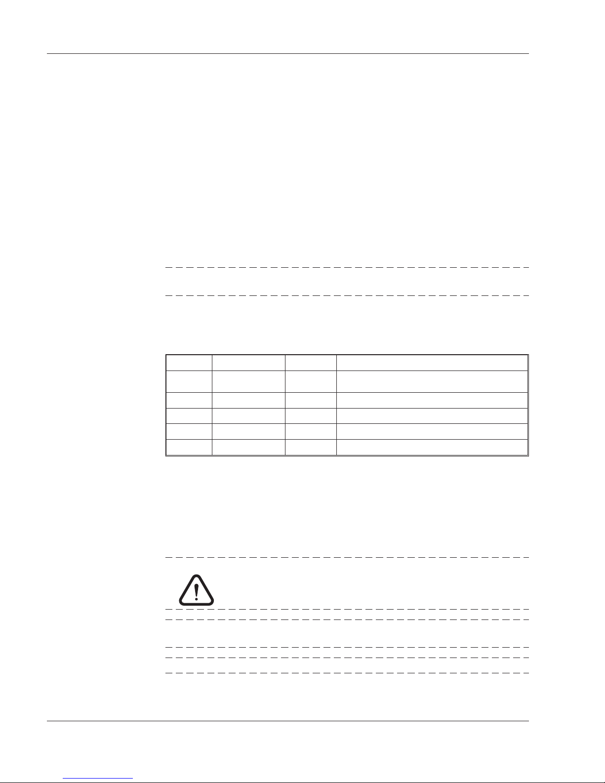
Menu Tree
Operator manual
2 - 6 TVS-D 660 LC-Display
Menu Operation
Page 11

HOME Menu
The sub-menus are all accessible via keys.
In the HOME MENU the following parameters are permanently displayed:
Parameter Remark
L, R, M, A*, B* Indication of the operation mode toggels
between L (local) , R (remote), M
(monitoring), A* (active devices) and B*
(backup devices).
ERROR/ WARNING/ INFO Indication of present errors / warnings/
additional information
* only in a spare sytem
Three operation modes are available to meet different user requirements:
In the LOCAL operation mode remote control is completeley disabled (no remote control
- signalling depends on the local setting).
In the REMOTE operation mode (so in A and B ) local indication, but no local control is
possible.
In the MONITORING mode local control is possible only after entering the password
(local password-protected mode).
Use the remote switch on the front-panel to switch between local and remote operation
mode.
Move the cursor to SIGNALING IF LOCAL to switch the remote signalling for local
operations on or off.
NOTE: Only visible if the remote interface is selected in the installation
menu
Change to the ACCESS submenu in the MISCELLANEOUS menu to activate/deactivate
the MONITORING mode.
The active operation mode is indicated by the LC-display, which will change from L
(local / local with signalling “loc sig”) to R (remote) or M (monitoring).
Operator manual
TVS-D 660 LC-Display 2 - 7
Menu Operation
Page 12

Move the cursor to ERROR / WARNING or INFO to view a record of errors, warnings
and other information. The record contains information about the module or unit the
messages are originating from, the type of information (E/W/I) and plain-text messages.
Max. 7 entries are listed in the record. The indication (e.g. WARNING) on the LCD
refers to the message type with the highest priority - errors rank above warnings and
other information.
Operator manual
2 - 8 TVS-D 660 LC-Display
Menu Operation
Page 13
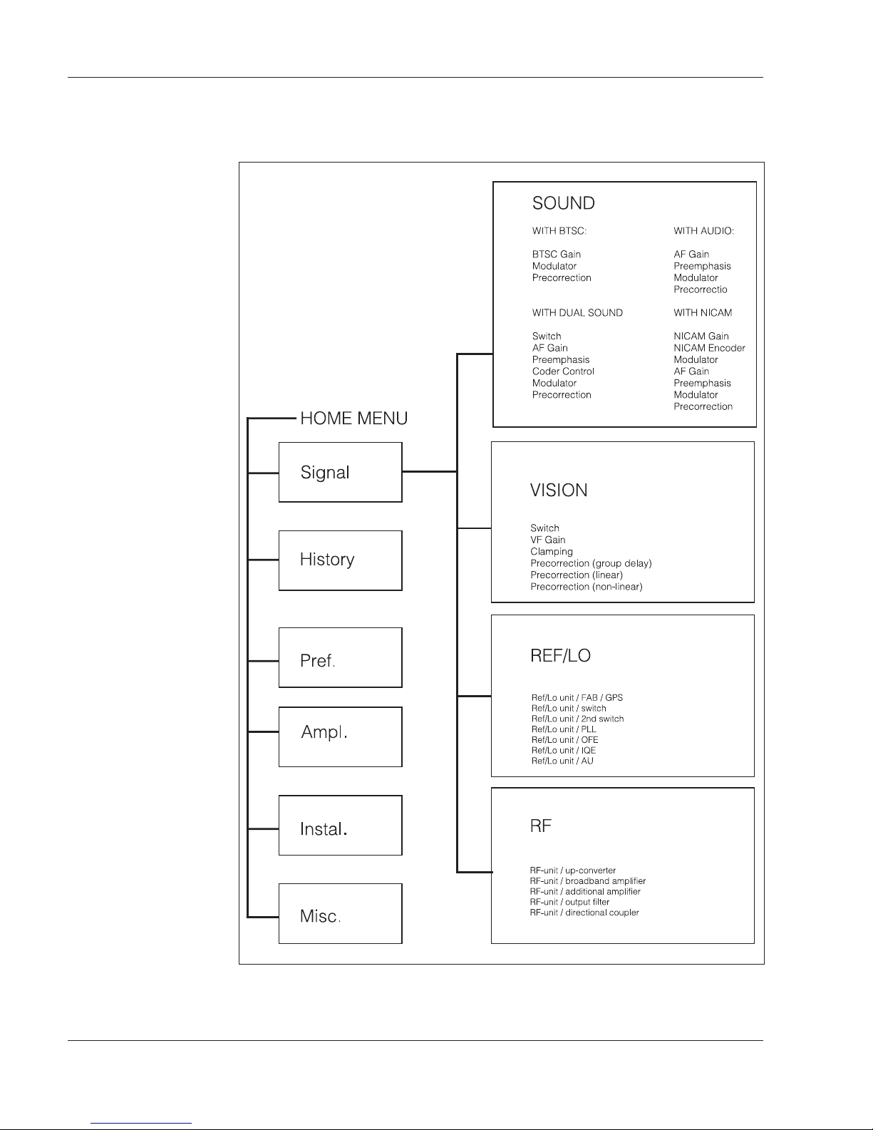
SIGNAL PROCESSING Menu
In the SIGNAL PROCESSING menu the following parameters are permanently
displayed:
Parameter Remark
VF-IN Indication of the VF input level
INPUT Indication of the availability of the input
signal (Smiley / Weepy) and the input
source (MAIN / AUX)
REF. FREQ. Indication of the reference signal for the
OCXO (10MHz oscillator)
(1pps, 100kHz, 500kHz,1MHz, 2,048MHz,
5MHz, 10MHz oscillator)
FREQ. Indication of the RF vision carrier
frequency
RATED RF LEVEL Indication of the rated RF output level
RF-OUT Indication of the deviation from the rated
RF-level in dB
Operator manual
TVS-D 660 LC-Display 2 - 9
Menu Operation
Page 14
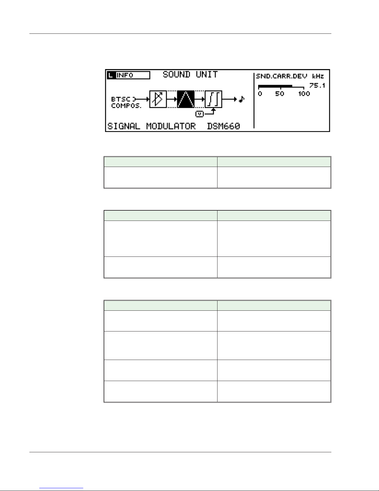
BTSC SOUND UNIT Menu
In the SOUND UNIT menu the following parameter is permanently displayed:
Parameter Remark
SND.CARR. DEV.
Indication of the sound carrier deviation
in kHz (The nominal deviation is 75 kHz).
Sound Unit Menu / BTSC GAIN
Parameter Remark
BTSC COMPOSITE INPUT GAIN
Sets the gain of the BTSC composite
input. The range is -9.9 to +6 dB. This
directly affects the sound carrier
deviation.
DETECTOR DECAY
Defines the speed at which the indication
bar returns to the zero position(fast/slow).
Sound Unit Menu / MODULATOR
Parameter Remark
SOUND CARRIER
Selection for the BTSC sound carrier
(OFF / ON)
SOUND CARRIER LEVEL
Adjustment of the BTSC sound carrier
level in dB - relative to peak sync of the
vision carrier range.
DEVIATION LIMITER
Selection for the deviation limiter - the
deviation limit is at 120 kHz (OFF / ON)
LIMITER ACTIVE
Indication whether the deviation limiter
has responded or not (YES / NO)
Operator manual
2 - 10 TVS-D 660 LC-Display
Menu Operation
Page 15

Sound Unit Menu / PRECORRECTION
Parameter Remark
VISION-SOUND CROSSMOD, /
CORRECTOR
Selection for the vision-sound
crossmodulation corrector (OFF / ON) reduces distortions and is defined with
the settings below.
DELAY FACTOR
Defines the delay factor for the
vision-sound crossmodulation correction
GAIN FACTOR
Defines the gain factor for the
vision-sound crossmodulation correction
Operator manual
TVS-D 660 LC-Display 2 - 11
Menu Operation
Page 16
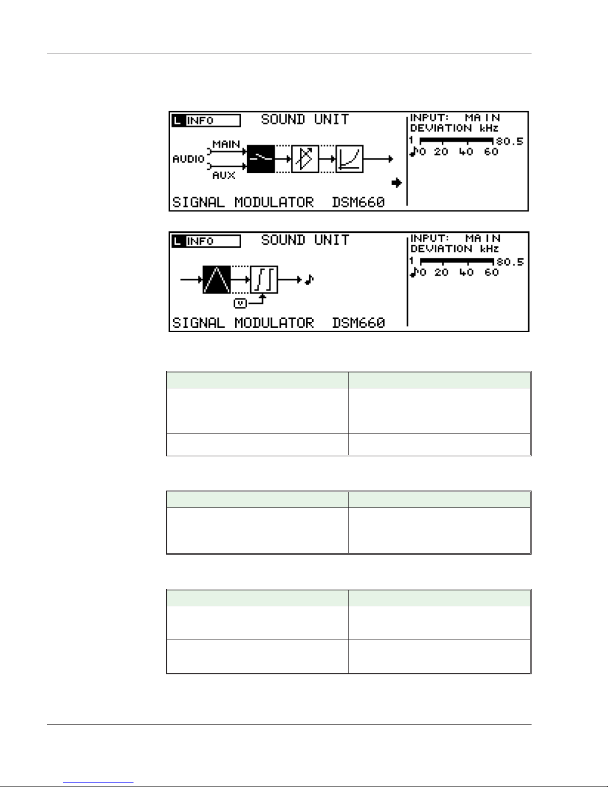
AUDIO SOUND UNIT Menu (FM MONO)
In the SOUND UNIT menu the following parameters are permanently displayed:
Parameter Remark
INPUT
In this specific audio mode two different
inputs are available (MAIN / AUX) on the
front-panel
DEVIATION
Indication of the deviation in kHz
Sound Unit Menu / SWITCH
Parameter Remark
THE AF SOURCE SELECTION
FOLLOWS VIDEO
Depending on the video setting, the
transmitter switches from MAIN sound to
AUX sound and vice versa.
Sound Unit Menu / AF GAIN
Parameter Remark
AF GAIN SND1
Setting of the AF gain for the sound input
in the range of -9.9 ...+6dB
DETECTOR DECAY
Defines the speed at which the indication
bar returns to the zero position(fast/slow).
Operator manual
2 - 12 TVS-D 660 LC-Display
Menu Operation
Page 17

Operator manual
TVS-D 660 LC-Display 2 - 13
Menu Operation
CONTROL TONE DETECTOR
Activation of the control tone detector at
22.5 kHz (ON/OFF) - for standard I only.
CONTROL TONE PRESENT
Indication of the presence of the control
tone (Smiley / Weepy) - detector has
responded or not.
Sound Unit Menu / PREEMPHASIS
Parameter Remark
PREEMPHASIS
Selection among three values for the
audio preemphasis: OFF,
50 ms, and 75 ms
Sound Unit Menu / MODULATOR
Parameter Remark
SOUND CARRIER 1 Selection for sound carrier 1 (ON / OFF)
SND. CARRIER LEVEL Indication of the sound carrier level in dB
- relative to the peak sync of the vision
carrier
DEVIATION LIMITER (softkey) Selection for the DEVIATION LIMITER
(OFF/60/90/120 kHz) / Indication of the
LIMITER 1 ACTIVE: YES / NO (shows
the status of limiter 1).
Sound Unit Menu / PRECORRECT.
Parameter Remark
VISION-SOUND CROSSMOD. /
CORRECTOR
Selection (OFF / ON)
DELAY FACTOR
Defines the delay factor for the
vision-sound crossmodulation correction
GAIN FACTOR
Defines the gain factor for the
vision-sound crossmodulation correction
Page 18

DUAL SOUND UNIT Menu
In the SOUND UNIT menu the following parameter is permanently displayed:
Parameter Remark
INPUT
In this specific audio mode two different
inputs are available (MAIN / AUX) on the
front-panel
DEVIATION
Indication of the deviation in kHz
CODER
Shows the actual coding mode
DATALINE
Shows if there is information about the
sound standard in the dataline (Smiley /
Weepy)
TTX
Shows if there is information about the
sound standard in the teletext (Smiley /
Weepy)
Sound Unit Menu / Switch
Parameter Remark
THE AF SOURCE SELECTION
FOLLOWS VIDEO
Depending on the videosetting, the
transmitter switches from MAIN sound to
AUX sound and vice versa.
Operator manual
2 - 14 TVS-D 660 LC-Display
Menu Operation
Page 19

Sound Unit Menu / AF Gain
Parameter Remark
AF GAIN SND1
Setting of the AF gain for the sound 1
input in the range of -9.9 ...+6dB
AF GAIN SND2
Setting of the AF gain for the sound 2
input in the range of -9.9 ...+6dB
DETECTOR DECAY
Defines the speed at which the indication
bar returns to the zero position(fast/slow).
Sound Unit Menu / Preemphasis
Parameter Remark
PREEMPHASIS
Selection among three values for the
audio preemphasis: OFF,
50 ms, and 75 ms
Sound Unit Menu / Coder Control
Parameter Remark
CTRL - MODE
Selection of the control mode (AUTO /
MAN)
HIGH PRIORITY
Selection of the most prioritiest mode of
coding (DATA / TXT)
MANUAL CODING
Selectioning the kind of the outcoming
signal ( MONO / DUAL / STEREO )
ACTUAL CTRL SOURCE
Indicates the present control source
(MANUAL / DATALINE / TTX (teletext))
Sound Unit Menu / Modulator
Parameter Remark
SOUND CARRIER 1
Selection for sound carrier 1 (ON / OFF)
(sound carrier 5.5 MHz relative to the
vision carrier)
SOUND CARRIER 2
Selection for sound carrier 2 (ON / OFF)
(sound carrier 5.742 MHz relative to the
vision carrier)
SND. CARRIER 1 LEVEL
Indication of the sound carrier 1 level in
dB - relative to the peak sync of the
vision carrier
Operator manual
TVS-D 660 LC-Display 2 - 15
Menu Operation
Page 20

SND. CARRIER 2 LEVEL
Indication of the sound carrier 2 level in
dB - relative to the peak sync of the
vision carrier
PILOT
Selection for the pilot (ON / OFF)
DEVIATION LIMITER (softkey)
Selection for the DEVIATION LIMITER
(OFF/60/90/120 kHz) Indication of the
LIMITER 1 ACTIVE: YES / NO (shows
the status of limiter 1) and incation of
LIMITER 2 ACTIVE: YES / NO
Sound Unit Menu / Precorrection
Parameter Remark
VISION-SOUND CROSSMOD. /
CORRECTOR
Selection (OFF / ON)
DELAY FACTOR
Defines the delay factor for the
vision-sound crossmodulation correction
GAIN FACTOR
Defines the gain factor for the
vision-sound crossmodulation correction
Operator manual
2 - 16 TVS-D 660 LC-Display
Menu Operation
Page 21

NICAM SOUND UNIT Menu
In the SOUND UNIT menu the following parameter is permanently displayed:
Parameter Remark
LEVEL
Indication of the M1/L and the M2/R level
CODER
Shows the actual coding mode
DATALINE
Shows if there is information about the
sound standard in the dataline (Smiley /
Weepy)
TTX
Shows if there is information about the
sound standard in the teletext (Smiley /
Weepy)
Sound Unit Menu / NICAM Gain
Parameter Remark
NICAM GAIN SND1
Setting of the NICAM gain for the sound
1 input in the range of -9.9 ...+6dB
M1 / L LEVEL
setting the level of the M1 / L Level in
dBu ( 0 dBu entspricht 0.775 VRMS )
NICAM GAIN SND2
Setting of the NICAM gain for the sound
2 input in the range of -9.9 ...+6dB
Operator manual
TVS-D 660 LC-Display 2 - 17
Menu Operation
Page 22

M2 / R LEVEL
setting the level of the M2 / R Level in
dBu ( 0 dBu entspricht 0.775 VRMS )
DETECTOR DECAY
Defines the speed at which the indication
bar returns to the zero position(fast/slow).
PREEMPHASIS
Setting the NICAM preemphasis
according to ITV - T Rec. J.17 (ON/OFF)
Sound Unit Menu / NICAM Encoder
Parameter Remark
CTRL - MODE
Selection of the control mode (AUTO /
MAN)
HIGH PRIORITY
Selection of the most prioritiest mode of
coding (DATA / TXT)
MANUEL CODING
Selectioning the kind of the outcoming
signal ( MONO / DUAL / STEREO )
ACTUAL CTRL SOURCE Indicates the actual control source
RESERVE FLAG
Switches the Reserve Sound Switching
Flag in th NICAM coder ( ON / OFF )
Sound Unit Menu / Modulator
Parameter Remark
SOUND CARRIER 1 Selection for NICAM sound 1 (ON / OFF)
SND. CARRIER LEVEL Indication of the NICAM sound carrier
level (-30,0dB ... -18,0dB) - relative to the
peak sync of the vision carrier
DEVIATION LIMITER (softkey) Selection for the DEVIATION LIMITER
(OFF/60/90/120 kHz) / Indication of the
LIMITER 1 ACTIVE: YES / NO (shows
the status of limiter 1).
Sound Unit Menu / AF Gain
Parameter Remark
AF GAIN SND1
Setting of the AF gain for the sound input
in the range of -9.9 ...+6dB
DETECTOR DECAY
Defines the speed at which the indication
bar returns to the zero position(fast/slow).
Operator manual
2 - 18 TVS-D 660 LC-Display
Menu Operation
Page 23

Sound Unit Menu / Preemphasis
Parameter Remark
PREEMPHASIS
Selection among three values for the
audio preemphasis: OFF,
50 ms, and 75 ms
Sound Unit Menu / Modulator
Parameter Remark
SOUND CARRIER 2 Selection for sound carrier 1 (ON / OFF)
SND. CARRIER 2 LEVEL Indication of the sound carrier level
(-10,0dB...-15dB) -relative to the peak
sync of the vision carrier
DEVIATION LIMITER (softkey) Selection for the DEVIATION LIMITER
(OFF/60/90/120 kHz) / Indication of the
LIMITER 1 ACTIVE: YES / NO (shows
the status of limiter 1).
Sound Unit Menu / Precorrection
Parameter Remark
VISION-SOUND CROSSMOD. /
CORRECTOR
Selection (OFF / ON)
DELAY FACTOR
Defines the delay factor for the
vision-sound crossmodulation correction
GAIN FACTOR
Defines the gain factor for the
vision-sound crossmodulation correction
Operator manual
TVS-D 660 LC-Display 2 - 19
Menu Operation
Page 24

VISION UNIT Menu
In the VISION UNIT menu the following parameters are permanently displayed:
Parameter Remark
INPUT
Indication of the Main / Aux video input
on the rear-panel / terminal board
VF SIG.
Indication of the availability of the VF
signal (Smiley / Weepy)
INPUT DEV.
Deviation in dB from the nominal level
(there are different criteria for the level
control - see VF gain control mode)
WHITE
Indication of the white level in mV
SYN. LEV.
Indication of the sync level in mV
RES. CAR.
Indication of the residual carrier in %
VF
Indication of the VF control mode
(manual gain control MGC, automatic
gain control AGC)
Operator manual
2 - 20 TVS-D 660 LC-Display
Menu Operation
Page 25

VISION UNIT Menu / SWITCH
Parameter Remark
INPUT SWITCHING MODE
Input selection (MAIN / AUX / AUTO)
PRESELECTED INPUT
Preselected input selection (MAIN / AUX)
NOTE: If a a reset is performed and the
transmitter runs in the input switching
mode AUTO and MAIN or AUX is selected
as standard input, the preselected input
will be used first.
SWITCH-OVER HANDLING (softkey)
WAIT FOR SWITCH-OVER (in s):
Defines how long the transmitter is
waiting after a signal loss, before the
switch-over takes place.
MAX. SWITCH COUNTER: Defines how
many switch-overs are allowed.
ACT. WAIT FOR SWITCH-OVER: Elapsed
time
ACT. SWITCH COUNTER: Number of
performed automatic switchings
CLEAR ACTUALS: Pressing the button
will clear the present values.
Operator manual
TVS-D 660 LC-Display 2 - 21
Menu Operation
Page 26

VISION UNIT Menu / VF GAIN
Parameter Remark
CONTROL MODE
Selection of the VF gain control mode
(SYNC / WHITEALL / TESTLINE /
MANUAL)
ON GAIN CONTROL FAIL
Selection for the gain control fail
handling:
AUTO - in case the control mode fails to
work properly the transmitter tries to
recover the signal by modifying the gain.
MANUAL - There is a plausibility check
for the white/sync ratio. The white/sync
values are adapted as needed to regain
a useful signal. If however the control
fails, the transmitter switches to the
manual mode in the end.
MANUAL GAIN
Setting of the manual gain in dB
(-3.0dB...+6.0dB)
VISION MODULATION
Switch for the vision modulation
(ON/OFF)
RESIDUAL CARRIER
Setting of the residual carrier in %
relative to peak sync level for the nominal
input
TESTLINES (softkey)
Only visible if TESTLINE is set in
CONTROL MODE (above). Permits to
define the testlines in field 1 and 2 in a
sub-menu.
VISION UNIT Menu / CLAMPING
Parameter Remark
WHITE LIMITER
Switch for the white limiter (OFF / ON)
THRESHOLD % P-SYNC
Setting of the white limiter threshold
(relative to peak sync of the
vision-carrier)
WHITE LIMITER ACTIVE
Indication of the activity of the white
limiter (YES / NO)
SYNC REGENERATION
Switch for the sync regeneration (OFF /
ON)
Operator manual
2 - 22 TVS-D 660 LC-Display
Menu Operation
Page 27

VISION UNIT Menu / PRECORRECTION (group delay)
Parameter Remark
REC. GROUP DELAY PREC.
Selection for the receiver group delay
precorrection (OFF / ON)
VISION UNIT Menu / PRECORRECTION (linear)
Parameter Remark
LINEAR PRECORRECTION /
FREQUENCY SLOPE
Serves to correct the frequency response
in the RF-path; can be set in the range of
± 1.5 dB / 8 MHz
AMPLITUDE COMP.
The amplitude compensation can be set
in the range of 0,0...1,0 dB only for IQE ³
version 2.20
LINEAR PRECORRECTION /
GROUPDELAY COMP.
Selection of the filter type (See plots 1-4
below) - for group delay compensation.
LINEAR PRECORRECTION / CHR. LUM.
DELAY
Setting of the chroma luminance delay in
the range of -16 … + 15.5 ns
Operator manual
TVS-D 660 LC-Display 2 - 23
Menu Operation
Figure: Linear Precorrection with Filter
Type 1
Figure: Linear Precorrection with Filter
Type 2
Page 28

Operator manual
2 - 24 TVS-D 660 LC-Display
Menu Operation
Figure: Linear Precorrection with
FilterType 4
Figure: Linear Precorrection with
FilterType 3
Page 29

VISION UNIT Menu / PRECORRECTION (non-linear)
Parameter Remark
Precorrection
Switch for the precorrection (OFF / ON)
SCALE CALIBRATION
Setting of the scale calibration dB
AM-AM
Setting of the AM to AM precorrection
values in the range of ±3dB
AM-PM
Setting of the AM to PM precorrection
values in the range of ±18°
PRESETS
For restoring default or saved values
(overriding manual settings)Selection
load, save, clear presets
Operator manual
TVS-D 660 LC-Display 2 - 25
Menu Operation
Page 30

REF / LO UNIT Menu
With GPS
Without GPS
Operator manual
2 - 26 TVS-D 660 LC-Display
Menu Operation
Page 31

REF / LO UNIT Menu / GENERAL
In the REF/LO unit the following parameters are permanently displayed:
Parameter Remark
TUNING OCXO Indication of the tuning voltage from the
OCXO (+/-)
TUNING OUTPUT VCO Indication of the output VCO tuning
OCXO LOCK Indication of the OCXO locking (Smiley /
Weepy)
OUT. LOCK Indication of the output PLL locking
(Smiley / Weepy)
In the REF/LO unit the following parameters can be defined and checked:
REF/LO UNIT Menu / FAB
Only accessible, if the GPS option is mounted
Parameter Remark
GPS SIGNAL 1 PPS Indication of the availability of the 1 pps
GPS signal (Smiley / Weepy)
GPS STATUS Indication of the GPS status (e.g.
SEARCH)
USED SATELLITES Indication of the number of used satellites
VISIBLE SATELLITES Indication of the number of visible
satellites
ANT. DELAY COMP. Input of the antenna delay compensation
SAT MEASUREMENTS (soft-key) Indication of SAT measurements (click
ENTER to view C/N, Azimuth and
elevation data for satellite 1 to 5)
REF/LO UNIT Menu / SWITCH
Only accessible, if the GPS option is mounted
Parameter Remark
SWITCHING MODE Switching mode selection (AUTO / 1 PPS
EXT / 1 PPS GPS)
HIGH PRIORITY High priority selection (1 PPS EXT / 1
PPS GPS)
1PPS EXT Indication of the 1 pps external signal
(Smiley / Weepy)
1 PPS GPS Indication of the availability of the 1 pps
GPS signal (Smiley / Weepy)
ACT. PPS SOURCE Indication of the used pps source
Operator manual
TVS-D 660 LC-Display 2 - 27
Menu Operation
Page 32

REF/LO UNIT Menu / 2nd SWITCH
Parameter Remark
SWITCHING MODE Switching mode selection (AUTO / 1 PPS
/ REF)
HIGH PRIORITY High priority selection (1 PPS / REF)
SELECT REF. Reference signal selection (100 kHz, 500
kHz, 1 MHz, 2,048 MHz, 5MHz, 10MHz)
REF. SIGNAL Indication of the availability of the
reference signal (Smiley / Weepy)
ACT. OCXO CTRL Indication of the present OCXO control
signal (e.g. 1 PPS)
REF/LO UNIT Menu / PLL
Parameter Remark
1 PPS Processing Indication of the 1 pps processing (Smiley
/ Weepy)
MODE OCXO OCXO mode selection (AUTO / MANUAL)
MANUAL TUNING Input of manual tuning (0 - 99,9 %)
RF OFF IF CTRL FAIL Selection (yes / no)
GUARD INTERVAL Input of the guard interval (5 - 50%)
REF/LO UNIT Menu / DSM
Parameter Remark
CLOCK FROM IQE Indication (Smiley / Weepy)
REF/LO UNIT Menu / PRECORRECTION
Parameter Remark
CLOCK FROM FAB Indication (Smiley / Weepy)
: Operator manual
2 - 28 TVS-D 660 LC-Display
Menu Operation
Page 33

REF/LO unit / UP-CONVERTER
Parameter Remark
VISION CARRIER FREQ Input of the center frequency
(470 - 862 MHz for Band IV/V)
(174 - 230 MHz for Band III)
COARSE OFFSET Input of the coarse offset
(-249 kHz - 249 kHz)
FINE OFFSET Input of the fine offset
(-999 - 999 Hz)
Operator manual
TVS-D 660 LC-Display 2 - 29
Menu Operation
Page 34

RF-Menu
6 HU - 200 mW
With RCU
RF-UNIT Menu / GENERAL
In the RF-menu the following parameters are permanently displayed:
Parameter Remark
RF-OUTPUT Indication of the deviation from
the rated RF-level
REFL. Indication of the reflection in dB
BBV Indication of the gain control (MGC /
AGC)
AMP MODE Indication of the amplifier mode (ON /
OFF)
Operator manual
2 - 30 TVS-D 660 LC-Display
Menu Operation
Page 35

AMP STATE Indication of the amplifier state (ON /
OFF)
In the RF unit the following parameters can be defined and checked:
RF-UNIT Menu / UP-CONVERTER
Parameter Remark
VISION CARRIER FREQ. Indication of the adjusted frequency
CARRIER OFFSET Indication of the adjusted offset
RF-UNIT Menu / BROADBAND AMPLIFIER
Parameter Remark
GAIN CONTROL Selection of the gain control (AUTO /
MANUAL)
MANUAL GAIN Input of the manual gain (0,0 - 25,000 dB)
DEVIATION FROM NOMINAL GAIN Indication of the deviation from nominal
gain
NOTE: This menu entry is not present, if
a RCU 8600 is installed. In this case the
menu entry “DEVIATION FROM
OPTIMAL PA GAIN” appears. This entry
refers to the deviation (in dB) between the
current gain level of amplifier´s AGC and
its optimal gain level. Adjust the exciter
output level to achieve a minimum
deviation. Afterwards press “SET GAIN
TO NOMINAL” and, if desired, switch
GAIN CONTROL to AUTO. If a WEEPY is
visible, there is no nominal point set for
the current configuration. Press “SET
GAIN TO NOMINAL” to set a nominal
point, and the WEEPY will vanish.
SET GAIN TO NOM. PERFORM key for setting gain to nominal
value
NOTE: This key is for compensating
output deviations (e.g. due to ageing or
manual adjustment.
RF-UNIT Menu / PA or Amplifier
Parameter Remark
NOMINAL OUT. POWER Indication of the nominal output power
RACKPHASE RCU x Input of the signal phase for the amplifier
racks (±40°). Only for RCU-systems.
RF-UNIT Menu / OUTPUT FILTER
Parameter Remark
VISION CARRIER FREQUENCY Indication of the adjusted frequency
Operator manual
TVS-D 660 LC-Display 2 - 31
Menu Operation
Page 36

RF-UNIT Menu / DIRECTIONAL COUPLER OR BBV
Parameter Remark
INC RATED RF OUT Input of the incident rated RF-output
signal (type power -10 ... +3)
INC CALIBR. VALUE Input of the incident calibration value (-5 -
5 dB)
NOTE: If the indicated output level does
not match the measured output level on
the RF-output of the DTV-transmitter, the
calibration factor can be added to the
indicated value (for the first start-up this
has already been done in the factory).
INC WARNING THRES. Input of the incident warning threshold (-5
... -0,5 dB)
INC. ALARM THRESH. Input of the incident alarm threshold (-8 ...
-3 dB))
REFL. CALIBR. VALUE Input of the reflection calibration value (-5
... 5 dB), not visible for 6 HU BBV
REFL. ALARM THRESH. Input of the reflection alarm threshold (-24
.... -13 dB), not visible for 6 HU BBV
RF-UNIT Menu / DIRECTIONAL COUPLER 1
(Only with RCU)
Parameter Remark
INC / REFL POWER Indication of incident and reflected power
for amplifier racks
RF-UNIT Menu / DIRECTIONAL COUPLER 2
(Only with RCU)
Parameter Remark
INC RATED RF OUT Input of the incident rated RF-output
signal (type power -10 ... +3)
INC CALIBR. VALUE Input of the incident calibration value (-5 -
5 dB)
INC WARNING THRES. Input of the incident warning threshold (-5
... -0,5 dB)
INC. ALARM THRESH. Input of the incident alarm threshold (-8 ...
-3 dB)
REFL. CALIBR. VALUE Input of the reflection calibration value (-5
... 5 dB), not visible for 6 HU BBV
REFL. ALARM THRESH. Input of the reflection alarm threshold (-24
.... -13 dB), not visible for 6 HU BBV
Operator manual
2 - 32 TVS-D 660 LC-Display
Menu Operation
Page 37

HISTORY Menu
The HISTORY menu permits to view and check messages from the transmitter system.
Parameter Remark
BEGIN ... END Error message with date/time information.
Each line contains max. 40 characters.
Max. three lines are assigned to a single
error. Up to 70 errors can be displayed in
the log.
CLEAR Pressing the CLEAR key will delete the
entries of the history.
PREFERENCES
Menu
The PREFERENCES menu is meant for storing and loading preferences.
Parameter Remark
LOAD This key permits to re-load settings that
were saved before.
SAVE All settings of the installation can be
saved.
Operator manual
TVS-D 660 LC-Display 2 - 33
Menu Operation
Page 38

AMPL. Menu
The AMPLIFIER menu serves to control crucial settings for the amplifier.
Parameter Remark
AMPLIFIER MODE Selection of the amplifier mode (auto / on
/ off / service)
- AUTO: amplifier is on if input signal is
present / standard operation
- OFF: amplifier is off
- ON: amplifier is on, if there is no error
- SERVICE: amplifier is on (reserved for
trained staff)
AMPLIFIER STATE Indication of operating state of the
amplifier (on / off)
POWER-OFF DELAY TIME Input of the delay time in s. When the
input signal is missing, the power
amplifier is switched off according to the
set delay time (in the AUTO-mode)
ACTUAL DELAY TIME Indication of the delay time elapsed so far
in s
REFLECTION HANDLING
- RED. TO POWER-OFF
- POW. OFF TO RETRY ON
- MAX. REFL. COUNTER
- CLEAR TIME FOR COUNTER
- CLEAR ACTUALS
Press the ENTER key to open the
reflection handling menu (defines how the
transmitter reacts to reflections) - see the
operating manual of the transmitter,
section "Maintenance/Reflection
handling", for further information.
WARNING HANDLING
- RED. TO POWER OFF
- POWER OFF TO RETRY ON
- MAX. WARNING COUNTER
- CLR. TIME FOR COUNTER
- CLEAR ACTUALS
Press the ENTER key to open the
warning handling menu. In the warning
handling menu the response of the
TV-transmitter to incoming warnings of
additional amplifiers can be defined.
Operator manual
2 - 34 TVS-D 660 LC-Display
Menu Operation
Page 39

INSTAL. Menu
The INSTALLATION menu serves the purpose of specifying basic transmitter settings.
Parameter Remark
STANDARD Selection of the transmission standard
(B/G, M, D/K, I, N, K1)
OUTPUT BAND Selection of the output band (Band III or
Band IV/V)
NOMINAL POWER EXT. Adjustment of the nominal output power
BIV/V: 200 mW / 500 mW
BIII: 200mW 6 HU
If an external amplifier is present, "Exciter
Power" is indicated instead of nominal
out. power.
REMOTE CONTROL Selection of the remote interface
- no interface
- relay (only without com-unit)
- relay + RS232 (only with com-unit)
- relay + RS485 (only with com-unit)
ADDITIONAL AMPL.:
- ADDITIONAL AMPLIFIER / CTRL:
Selection of the control interface for the
additional amplifier (ABSENT /
PARALLEL / RS 485 / RCU 8600)
NOMINAL POWER EXT. Input of the nominal output power (47 ...
80 dBm) or setup the power class of RS
485 amplifiers. This entry is not visible if
ADD. AMP. CTRL is set to ABSENT.
DETECTOR FACTOR (4V) Input of the detector factor (47 ... 80
dBm). This entry is not visible if ADD
AMPL CTRL is set to PARALLEL.
NUMBER OF RACKS Number of amplifier racks (only with RCU)
AGC AT Selection of the point where the output
power is controlled (output / exciter)
BACKPORCH SYNC DELAY Input of the backporch synchronization
delay in ns
Operator manual
TVS-D 660 LC-Display 2 - 35
Menu Operation
Page 40

GPS RECEIVER Setting for the GPS receiver (enable /
disable)
SOUND SYSTEM Selection of the sound standard (AUDIO /
BTSC / DUAL / NICAM)
BLOWER CONTROL Selection of the blower control (present /
absent)
INTEGRATED UPS Selection of the UPS (absent / present)
COM UNIT Selection of the communication unit
(present / absent)
Operator manual
2 - 36 TVS-D 660 LC-Display
Menu Operation
Page 41

MISCELLANEOUS Menu
MISCELLANEOUS Menu / ABOUT
This menu contains important information about the installed software versions for use
by our service center. Some error types require to send this information to the service
center.
MISCELLANEOUS Menu / DATE/TIME
This menu permits to view, check and set the present time in the format yy:mm:dd and
hh:mm:ss for insertion into the error history. If the COM-Unit is mounted and the SNTP
option is on, this menu has no effect.
MISCELLANEOUS Menu / SUPPLY VOLTAGES/CURRENTS
This menu contains information about the input voltage, the supply voltages +5V, +12V,
-12V, amplifier 1 supply voltage, amplifier 2 supply voltage, amplifier current 1 ... 4 as
well as information about the acceptable ranges.
Operator manual
TVS-D 660 LC-Display 2 - 37
Menu Operation
Page 42

MISCELLANEOUS Menu / MODULE TEMPERATURES
The MODULE TEMPERATURES sub-menu serves the purpose of indicating the
module temperature in the power supply IF-unit, IF-precorrection, frequency processing
(FAB), broadband amplifier 1 … 4.
MISCELLANEOUS Menu / SPARE OPERATIONS (ONLY FOR SPARE SYSTEMS)
SWITCHOVER EVENTS: Set the events and the delay time for a swichover,
Operator manual
2 - 38 TVS-D 660 LC-Display
Menu Operation
Page 43

N+1 SETTINGS: Serves to save / load the settings for the N+1 system. Refers to the
calibration of the low-power stages A1 … A8. For more information about the
change-over handling see the TCM 8600 operating manual.
MISCELLANEOUS Menu / SYSTEM DATA
The SYSTEM DATA sub-menu shows the CPU cycle time in ms, the CPU operation
time in h, the power amplifier operation time in h and the left EEPROM write-cycles
in %.
MISCELLANEOUS Menu / OPERATION LOG
The operation log window contains information about specific events with date / time
information.
The COLD RESET button restores the default settings - readjustment of the equipment
is necessary. The COM RESET button causes the COM unit to restart.
Operator manual
TVS-D 660 LC-Display 2 - 39
Menu Operation
Page 44

MISCELLANEOUS Menu / UNITS
The UNIT sub-menu serves to view / set the measuring units to dBm, W or kW.
MISCELLANEOUS Menu / DATA INTERFACE
This menu permits to enter communication parameters for the remote control interfaces
on the front-panel (FRONT-INTERFACE CPU) and the rear-panel of the device (I/O
INTERFACE). If the COM 660 interface is present (see INSTALLATION menu), it is
possible to define various parameters for the ethernet interface here. If, however, the
COM 660 Unit is absent, it is possible to enter parameters for the RS232 interface and
the modem operation (Modem Setup, Modem Initialise or Modem Test).
MISCELLANEOUS Menu / DATA INTERFACE (with COM-Unit)
Operator manual
2 - 40 TVS-D 660 LC-Display
Menu Operation
Page 45

Parameter Remark
NETWORK INTERFACE (softkey) COM network parameter
IP addr.
Netmask
Gateway
DHCP ON / OFF
Device ID 1...255
PARALLEL INTERFACE
(OFF/ SIGNAL = Relay ON / CONTROL.
Relay and digital inputs ON)
BITBUS INTERFACE
OFF.......... Bitbus is off
SIGNAL...only GET COMMANDS
CONTROL......GET and SET
COMMANDS
Slave addr. of LPS
Bitbus Baudrate of LPS
Operator manual
TVS-D 660 LC-Display 2 - 41
Menu Operation
Page 46

MISCELLANEOUS Menu / SETUP MODEM ( without COM unit )
The SETUP MODEM sub-menu permits to enter basic settings like an initialisation string
for the modem configuration.
Parameter Remark
STATION Enter the station name
DIAL ON Specifies the event (NO DIALING / SUM
ERROR / SIGNAL ERRORS)
INITSTR Initialisation string
PREFIX “ATD”
PINCODE Setting the pincode for the GSM card
TEL.NR. 1: Setting the phone number for phone 1
TYP 1: Selection of the message type (ASCII /
SMS)
TEL.NR. 2: Enter the phone number for phone 2
TYP 2: Selection of the message type (ASCII /
SMS)
Operator manual
2 - 42 TVS-D 660 LC-Display
Menu Operation
Page 47

Appendix
Operator manual
TVS-D 660 LC-Display 3 - 1
Appendix
Page 48

Errors, warnings and other information
Errors
Message Meaning Solution
10MHZ OSCILLATOR
MISSING
Sub-assy is missing or
faulty.
Insert or change the
sub-assy in the FAB.
10 MHZ OSCILLATOR
THERMOSTAT
The sub-assy “10 MHz
oscillator” in the module “IF
unit” is faulty.
Change the sub-assy “10
MHz oscillator” and order a
new module (see the
operating manual “DTV 660
transmitter” for the ordering
number of the module).
10 MHZ OSCILLATOR
UNLOCKED
10 MHz oscillator unlocked. Change the sub-assy 10
MHz oscillator in the
module FAB.
10 MHZ REF.
FREQUENCY MISSING
The reference frequency for
the up-converter is missing.
Check the cabling, the
up-converter and the FAB.
ADDITIONAL AMPL. Error message from
external amplifier.
Check the amplifier.
AMPLIFIER CURRENT Power consumption of the
amplifier module is out of
the allowed range.
Check fuses of the
amplifier.
Check transistors and
change them.
Change the amplifier.
BLOWER VOLTAGE Blower switched off
because fault is present.
Supply voltage failure
Check the module power
amplifier
(DC/DC-converter).
BLOWER SYSTEM Fault in the power amplifier
blower system
Check RCU messages for
details
COOLING SYSTEM Fault in the liquid cooling of
the power amplifier system
Check RCU messages for
details
COMMUNICATION
DISTURBED
Communication between
monitoring program / COM
unit and CPU failed.
Switch on the mains.
Check the connections or
check the COM unit.
COMPAT. NUMBER NOT
MATCHING
Old version of the
monitoring program.
Module hardware / software
is of a higher version than
the CPU software.
EEPROM ACCESS Error in the CPU EEPROM. Change the module CPU.
FPGA ERROR FPGA module does not
work.
Restart the transmitter /
change the module.
FREQUENCY
PROCESSING
There is a problem in the
IQE.
Check the cabling on the
rear-panel OR change the
module.
HARDWARE ERROR Problem in module UPS,
IQE, AU or DSM.
Change the module.
INTERFACE DATA
CHECKSUM
Checksum (Communication
CPU -RCU)
The COM660 database is
corrupted. Please store the
settings for the interface
again.
IIC-BUS BLOCKED I2C-bus error - a module
cannot be accessed.
Pull out one module after
the other (except the CPU
and the POWER SUPPLY)
and check when the
message disappears -
change the faulty module.
Operator manual
3 - 2 TVS-D 660 LC-Display
Appendix
Page 49

MAINS FAILURE Failure of the power
amplifier system
Check RCU messages for
details.
MODULE MISSING Module is missing OR
Module is faulty.
Order the missing module.
Exchange the faulty
module.
NEED A NEW CPU
SOFTWARE
CPU software does not
match LCD version.
Update the CPU software.
NEED A NEW LCD
SOFTWARE
LCD software version does
not match CPU version
Update the LCD software.
NOT RUNNING The blower is faulty. Check the blower and, if
necessary, replace it.
OFF -ERROR STILL
PRESENT
Blower is switched off. Check the blower. If
necessary, change it.
OFF BECAUSE MODULE
TEMP. HIGH
The blower is faulty or the
ambient temperature is too
high.
Contact one of our service
centers and order a new
blower (see the operating
manual “DTV 660
transmitter” for the ordering
number of the blower.
OPERATING VOLTAGE
OUT OF RANGE
Operating voltage of the
transmitter is out of the
allowed range.
Check the mains voltage,
the transformator voltage
and check the module
POWER SUPPLY.
OUTPUT VCO UNLOCKED Output frequency out of the
allowed range.
Tune AU to the right
frequency..
POWER SUPPLY OFF Over-temperature SVG. —REFLECTION LEVEL
ABOVE LIMIT
Reflection level is too high
compared to the adjusted
threshold.
See description of reflection
handling in the transmitter
operating manual.
RF OFF. - REFLECTION
COUNTER
The reflection counter has
reached the maximum
value.
See description of reflection
handling.
RF OFF. - REFLECTION
LEVEL
Output power was switched
off because of exceeding
the limit for the reflection
value.
See description of reflection
handling in the transmitter
operating manual.
RF OFF - WARNING
COUNTER
The max. number of
reduction / switch-off cycles
was reached due to
exceeding the reflection
level
Go to the menu
“AMPLIFIER UNIT” to get
more information about
resuming operation.
RF OFF - WARNING STILL
PRESENT
The external warning is still
present
Go to the menu
“AMPLIFIER UNIT” to get
more information about
resuming operation.
RF OFF - OCXO
BACKUPTIME
The RF signal is switched
off because the hold time of
the OCXO without the
frequency locking is
exceeded.
Check the frequency
locking.
RF OFF - OCXO GUARD
INTERVAL
The RF signal is switched
off because the frequency
is out of the guard interval
(the OCXO control
frequency is out of range)
Check the frequency
locking.
RF OUTP.LEV.<
ALARMTHRES.
RF output level is below the
adjusted alarm threshold.
Check the RF-path.
Operator manual
TVS-D 660 LC-Display 3 - 3
Appendix
Page 50

SIGNAL PROCESSING There is a problem in the
IQE
Check the cabling on the
rear-panel OR change the
module.
STORAGE BATTERY
FAILURE
The storage battery is faulty
(UPS).
Change the battery.
SUPPLY VOLT. (S) OUT
OF RANGE
Output voltages +5V, +/- 12
V of the module POWER
SUPPLY are out of the
allowed range
Check the module POWER
SUPPLY.
Check the power
consumption of other
modules.
SUPPLY VOLTAGE OUT
OF RANGE
Power supply fault of the
amplifiers.
Change the amplifier.
TRANSIST.BIAS
CURRENT
Transistor bias current fault. Check fuses of the
high-power amplifier.
Check the transistors and
change them.
Change the high-power
amplifier.
WRONG MODULE TYPE A module is incompatible. Check the settings for the
module and equipment
types.
Change the module.
Warnings
Message Meaning Solution
10MHZ
OSC.TEMPERATURE
WRONG
The temperature of the 10
MHz oscillator of the
module FAB is wrong.
The thermostat may be
faulty
Change the sub-assy of the
frequency processing.
10 MHZ OSC. TUNING
NEAR LIMIT
Tuning voltage of the 10
MHz oscillator is near the
limit.
Change the sub-assy 10
MHz oscillator in the
module FAB.
1 PPS OF INTERNAL GPS
MISSING
The 1 PPS signal is absent. Check the GPS reception.
ABNORMAL OPERATION Abnormal operation in one of the processing units (RF,
AUDIO, VIDEO, REF/LO because:
- The transmitter runs in test mode.
- The IF-precorrector was set to OFF, the reference
frequence is selected manually, the output to MGC in
the RF-unit.
- The amplifier was set to ON / OFF / SERVICE.
CONTROL TONE MISSING There is no control tone. Check the input signal.
DEVICE UNLOCKED PA is set to OFF. Set switch from PA to ON.
ENVIR. TEMPERATURE
TOO HIGH
Ambient temperature is too
high
Check if the vents are not
blocked.
ENVIR. TEMPERATURE
TOO LOW
Ambient temperature is too low.
EXTERNAL 1PPS SIGNAL
MISSING
.... Check the connections.
EXTERNAL REFERENCE
FREQUENCY MISSING
.... Check the connections.
GAIN AT MAXIMUM ! The output gain is at the maximum.
GAIN AT MINIMUM ! The output gain is at the minimum.
LOW BATTERY Battery fault. Change the battery of the
CPU.
Operator manual
3 - 4 TVS-D 660 LC-Display
Appendix
Page 51

MAINS(1) FAILURE Indicates a mains break-down (mains 1)
MAINS(2) FAILURE Indicates a mains break-down (mains 2)
MUTING ACTIVATED Output of OFE is muted.
OCXO - BACKUPTIME
REACHED
Frequency out of guard interval because OCXO control
frequency is missing.
OCXO CTRL FREQUENCY
MISSING
1 pps and external reference frequency missing.
OCXO GUARD INTERVAL
PASSED
OCXO is now out of the
guard interval
OUTPUT FORCED MGC
SELECTED
Configuration was changed.
Reflection / Amplifier fault.
Check the antenna /
module. Change the gain.
OUTPUT OSC. TUNING
NEAR LIMIT
—- Tune the AU.
OVERTEMPERATURE Amplifier temperature is too
high
Check if the vents are not
blocked.
PA AGC DEVIATION There is a power amplifier
automatic gain control
deviation .
Optimise the power of the
broadband amplifier till the
deviation is “0”.
POLY FUSE RESPONDED A short-circuit may be
present.
Switch installation off and
on again.
POWER RED. - WARNING
INDICATED
An external warning was
detected.
See warning handling in the
transmitter operating
manual
POWER REDUCED. REFL. LEVEL
Reflection level too high power was reduced.
See reflection handling in
the transmitter operating
manual.
RF OUT. LEVEL <
WARNING THRES.
The amplification was not
properly adjusted.
Increase the amplification in
the menu “OUTPUT UNIT”,
until the RF output level is
above the adjusted
threshold.
RF-BLOCKING ACTIVE Signal line connected to
ground - no output power.
Check the installation.
SAFETYLOOP OPEN Safety loop interrupted - no
output power.
Check the connector on the
rack door.
SOC BLANKINGLOOP
ACTIVE
STORAGE BATTERY LOW The storage battery level is
low.
This message may appear
in the event of a mains
break-down. After 2
minutes the transmitter will
be shut down.
TESTMODE ACTIVE OFE is running in testmode Set Testmode OFF
Information
Message Meaning
1 PPS of internal GPS missing 1 PPS signal absent
10 MHZ OSC. TEMPERATURE LOW 10 MHz oscillator is heating up.
AMPL. MODE SERVICE SELECTED —AMPLIFIER MODE OFF SELECTED —AMPL. MODE ON SELECTED —COLD RESET DONE A cold reset was performed.
Operator manual
TVS-D 660 LC-Display 3 - 5
Appendix
Page 52

EEPROM WRITE CYCLES EXPIRED The maximal number of EEPROM
write-cycles was exceeded.
ERROR HISTORY FULL The max. number of entries in the
ERROR HISTORY was exceeded.
MAIN INPUT SIGNAL MISSING The input signal is missing or faulty.
NON-STANDARD PREEMPHASIS A non-default preemphasis is used with a
specific standard.
OCXO CTRL SET TO MANUAL The oscillator was tuned manually.
OCXO TEACH-IN IN PROGRESS Oscillator not yet in guard interval.
PERFORMING RESET Reset active.
RECEIVER GROUP DELAY OFF --RF OFF - SYSTEM PROTECTION Automatic RF blocking for system
protection.
TCM CTRL: LPS IN PASSIVE MODE The switch-over control switches the
low-power stage in the passive mode.
SELECTED TESTLINE(S) MISSING Check the testline settings.
STATION IN LOCAL CTRL. MODE You are in the local control mode
(read-only).
STATION IN MONITROING MODE You are in the monitoring mode.
STORAGE BATTERY CHARGING The UPS battery is being charged now.
SWITCH OVER CONTROLL
CONNECTED
The Switchover Control (SOC) is
connected to the LPS
WHITELIMITER OFF The white limiter has been turned off.
Check the settings in the vision menu.
WHITE LIMITER RESPONDING The white limiter has responded.
Operator manual
3 - 6 TVS-D 660 LC-Display
Appendix
 Loading...