

Page 1

TS®17 Portable Test Telephone
Description and Use
SPECIFICATIONS:
PHYSICAL
Length: 6¾ inches (17.1 cm)
Width: 2-3/8 inches (5.1 cm)
Height: 2½ inches (6.3 cm)
Storage Temperature: -20°C to +60°C
Operational Temperature: -5°C to +40°C
ELECTRICAL
Loop Limit: 2.4 kOhms at 48 Vdc
15mA minimum loop current)
Monitor Impedance:
6K Ohms, typical at 1 kHz
Off-Hook DC Resistance: 150 ohms typical
Rotary Dial (Pulse) Output:
Pulsing Rate: 10 pps ±1pps
Break/Make Ratio: 60/40 ±3%
Interdigit Interval: >300 ms
Leakage During Break: >50 kOhms
DTMF (Tone) Output:
Tone Frequency Error: ±1.5% (maximum)
Level Per Tone Pair: +1 dBm maximum,
High vs. Low Tone Difference:
2dB ±2dB
Telecom Electrical Safety Classification: TNV-3
Ordering Information:
Part Number Description
17800-500 TS17 Butt Set,
17800-000 TS17 Butt Set
IMPORTANT SAFETY PRECAUTION
Good safety practices prohibit the
■
connection of the TS17 Test Telephone and
similar test telephones to 115/230 Volts AC
commercial electrical power. If the TS17 Test
Telephone is connected to commercial power,
all warranties are immediately voided.
■ Not for Outdoor Use!
■ Legal Requirements may exist regarding
permission to connect equipment to a Telecom
network operated by a public network operator.
with Alligator
Clip Line Cord and
Belt Clip
(no line cord or belt clip)
FEATURES
The TS17 Portable Test Telephone
employs the latest technology in integrated
circuit design to provide:
■ Talk and Monitor Modes.
■ Tone (DTMF) and Pulse Signaling.
■ Continuous Polarity Indication.
■ Audible Ringer.
■ Listening for noise.
■ High Impedance Monitor Mode.
■ Field Replaceable Line Cord and
Belt Clip on some models.
This portable test telephone, often called
a "butt-in”, is a self-contained, line
powered (no battery required), portable
handset used by installers, repair
technicians, and other authorized
personnel for testing and temporary
communications on metallic voice type
telephone lines.
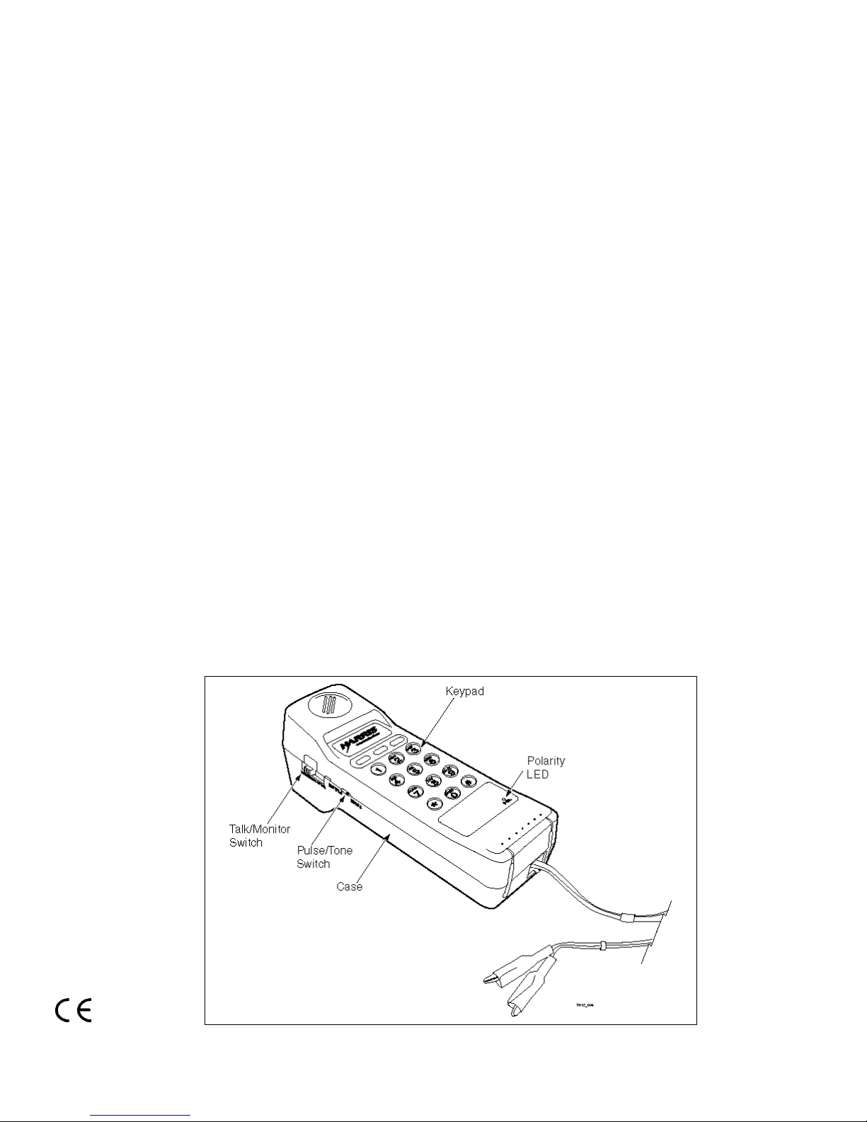
CONTROLS AND INDICATORS
TALK/MONITOR Mode. The test
telephone has a two-position slide switch
located on the side of the handgrip near
the receiver. The switch is labeled TALK/
MONITOR.
In the MONITOR position, the TS17 is
on-hook with a 6K Ohms impedance
audio coupling to the telephone line. This
allows for telephone line monitoring
without disrupting conversations, or
network signaling. In this position, the
TS17 also places an audible ringer
across the line.
In the TALK position, the TS17 is off-hook
and may be used for dialing and talking.
In this mode, the TS17 performs as an
ordinary telephone.
Audible Ringer. The TS17 Test
Telephone has an audible ringer to
indicate incoming calls when the test
telephone is in the MONITOR mode.
PULSE/TONE Switch. This two-position
slide switch, labeled PULSE/TONE, is
located on the side of the handgrip, just
below the receiver. The switch selects the
dialing type: TONE for DTMF dialing or
PULSE for pulse dialing.
Note: The TS17 is not polarity sensitive
and will function normally regardless of
telephone line polarity.
Polarity. The red LED, located below the
keypad area, will light up when the red
test lead is connected to a more positive
voltage than the black test lead.
Keypad. All 12 dialing keys will send
DTMF tones. Ten of the 12 keys send dial
pulses. Asterisk (❋) and pound (#) will not
send dial pulses. If the asterisk (❋) key is
pressed when the unit is in PULSE mode,
the dialing mode will be changed to tone
dialing.
OPERATION
Monitoring. Move the TALK/MONITOR
switch to MONITOR and connect the test
leads to the telephone line under test.
Monitoring may now be done without
disrupting traffic. Typical monitoring
applications include:
■ Verifying that the line under test is idle
before going off-hook.
■ Hunting for trace tones.
■ Listening for noise.
If the telephone lines under test include
data lines, it is best to use the MONITOR
mode when hunting for trace tones to
reduce the possibility of interrupting a data
service.
Polarity Check. Move the TALK/
MONITOR switch to TALK. The red LED
will not light if the red test lead is
connected to the ring (negative) side of the
line and the black test lead is connected to
the tip (positive) side of the line. The red
LED will light if the test leads are reversed;
that is, with the red test lead connected to
the tip (positive) side and with the black
test lead connected to the ring (negative)
side.
Dialing
1. Move the TALK/MONITOR switch to
the MONITOR position.
2. Move the PULSE/TONE switch to
either PULSE or TONE depending on
the type of signaling required.
3. Connect the line cord clips to the
telephone line and verify that the
telephone line is idle.
4. Move the TALK/MONITOR switch to
the TALK position. Listen for dial tone
(when furnished).
0II-727109-001, Issue 3, 2/00 1 Printed in Taiwan
Page 2
5. Enter the desired number to be
called on the keypad. If the test
telephone is in the TONE mode, the
tones associated with each digit will
be generated as each respective
button is pressed. If the test
telephone is in the PULSE mode, the
digits will be pulsed out at the correct
rate as the keys are pressed.
6. To end the call, return the TALK/
MONITOR switch to the MONITOR
position.
MAINTENANCE
Belt Clip Replacement. The belt clip
may be easily replaced in the field
without opening up the Portable Test
Telephone. The ordering number for the
replacement clip is P1780002. To replace
the belt clip, follow the instructions that
comes with the belt clip.
Line Cord Replacement. The line cord
may be replaced in the field. The ordering
number for the line cord is P1780001. To
replace the line cord, unplug the RJ11
jack from the end of the TS17 Test
Telephone and replace the cord with a
new one.
Warranty. Harris Corporation agrees to
warranty its products are free from defects in
material and workmanship for the following
periods:
■ Butt Sets and Test Telephones – 90
days from date of purchase.
■ Line Cords and Accessories – 90 days
from date of purchase.
This warranty constitutes the sole and
exclusive warranty for products sold by
Harris Corporation and is in lieu of any other
warranty, express, implied, or statutory,
including the warranty of merchantability and
fitness for a particular purpose. In no event
shall Harris be liable for any special,
incidental, indirect, or consequential
damages arising out of the use of any
product or from any other cause.
This warranty shall not apply to product
mishandling, abuse, misuse, negligence, or
accident, nor to products which have been
modified, altered, or repaired by personnel
not authorized by Harris.
Non-Warranty. Out-of-warranty
maintenance, service, or repair of products is
available from the Harris Corporation on a
time and materials basis. In addition,
Harris offers for sale some replacement
components. Harris Corporation
recommends that out-of-warranty service
and repair of electronic products be
completed at its Harris Communications
Products Division facility or authorized
representative. Contact Harris Repairs for
the location of the Harris authorized repair
facility nearest you.
Return or Repair of Equipment. The
return of any products for credit, other than
for warranty service, is done at the sole
discretion of Harris Corporation. Before
any product is returned, including for
warranty service, a Return Authorization
(“RA”) number must be obtained from the
Customer Service Department by calling
1-800-437-2266. If the RA number is not
clearly marked on the shipping label, the
package will not be accepted by Harris. All
authorized returns must be shipped, with
shipping charges prepaid, f.o.b.
destination, and addressed as follows:
Harris Communications Products Division
809 Calle Plano
Camarillo, California 93012-8516
United States of America
Attn.: Customer Support, RA# xxxxx
0II-727109-001, Issue 3, 2/00 2 Printed in Taiwan
 Loading...