

Page 1
Page 2

14221-1850-2000
2
MANUAL REVISION HISTORY
REV.
DATE
REASON FOR CHANGE
-
Sep/18
Initial release.
ACKNOWLEDGEMENT
This device is made under license under one or more of the following US patents: 4,590,473; 4,636,791; 5,148,482; 5,185,796; 5,271,017;
5,377,229; 4,716,407; 4,972,460; 5,502,767; 5,146,497; 5,164,986; 5,185,795; 5,226,084; 5,247,579; 5,491,772; 5,517,511; 5,630,011;
5,649,050; 5,701,390; 5,715,365; 5,754,974; 5,826,222; 5,870,405; 6,161,089; and 6,199,037 B1. DVSI claims certain rights, including
patent rights under aforementioned U.S. patents, and under other U.S. and foreign patents and patents pending. Any use of this software or
technology requires a separate written license from DVSI.
The Advanced Multi-Band Excitation implementation 2 (AMBE+2) voice coding Technology embodied in this product is protected by
intellectual property rights including patent rights, copyrights and trade secrets of Digital Voice Systems, Inc. This voice coding Technology
is licensed solely for use within this Communications Equipment. The user of this Technology is explicitly prohibited from attempting to
extract, remove, decompile, reverse engineer, or disassemble the Object Code, or in any other way convert the Object Code into a humanreadable form. U.S. Patent Nos. #5,870,405, #5,826,222, #5,754,974, #5,701,390, #5,715,365, #5,649,050, #5,630,011, #5,581,656,
#5,517,511, #5,491,772, #5,247,579, #5,226,084 and #5,195,166.
CREDITS
Harris, VIDA, NetworkFirst, and OpenSky are registered trademarks of Harris Corporation. TECHNOLOGY TO CONNECT, INFORM
AND PROTECT is a trademark of Harris Corporation.
Bluetooth is a registered trademark of Bluetooth SIG, Inc.
Motorola is a registered trademark of Motorola, Inc.
AMBE is a registered trademark and IMBE, AMBE+, and AMBE+2 are trademarks of Digital Voice Systems, Inc.
Wi-Fi is a registered trademark of Wi-Fi Alliance.
All brand and product names are trademarks, registered trademarks, or service marks of their respective holders.
NOTICE!
The material contained herein is subject to U.S. export approval. No export or re-export is permitted without written approval from the U.S.
Government. Rated: EAR99; in accordance with U.S. Dept. of Commerce regulations 15CFR774, Export Administration Regulations.
Information and descriptions contained herein are the property of Harris Corporation. Such information and descriptions may not be copied
or reproduced by any means, or disseminated or distributed without the express prior written permission of Harris Corporation, PSPC
Business, 221 Jefferson Ridge Parkway, Lynchburg, VA 24501.
Repairs to this equipment should be made only by an authorized service technician or facility designated by the supplier. Any repairs,
alterations or substitutions of recommended parts made by the user to this equipment not approved by the manufacturer could void the user's
authority to operate the equipment in addition to the manufacturer's warranty.
This product conforms to the European Union WEEE Directive 2012/19/EU. Do not dispose of this product in a public
landfill. Take it to a recycling center at the end of its life.
Harris products comply with the Restriction of the Use of Certain Hazardous Substances in Electrical and Electronic
Equipment (RoHS) Directive.
This manual is published by Harris Corporation without any warranty. Improvements and changes to this manual necessitated by typographical errors,
inaccuracies of current information, or improvements to programs and/or equipment, may be made by Harris Corporation at any time and without notice.
Such changes will be incorporated into new editions of this manual. No part of this manual may be reproduced or transmitted in any form or by any means,
electronic or mechanical, including photocopying and recording, for any purpose, without the express written permission of Harris Corporation.
Copyright © 2018 Harris Corporation.
Page 3

14221-1850-2000
3
TABLE OF CONTENTS
Section Page
1. REGULATORY AND SAFETY INFORMATION ............................................................................ 7
1.1 SAFETY SYMBOL CONVENTIONS ........................................................................................ 7
1.2 RF ENERGY EXPOSURE AWARENESS AND CONTROL INFORMATION FOR FCC
OCCUPATIONAL USE REQUIREMENTS .............................................................................. 7
1.2.1 Federal Communications Commission Regulations ....................................................... 8
1.3 COMPLIANCE WITH RF EXPOSURE STANDARDS ............................................................ 8
1.3.1 Mobile Antennas ............................................................................................................. 9
1.3.2 Approved Accessories ................................................................................................... 10
1.3.3 Contact Information ...................................................................................................... 10
1.4 REGULATORY APPROVALS ................................................................................................. 11
1.4.1 Applicable Type Acceptance/Certification Numbers .................................................... 11
1.4.2 FCC Part 15 ................................................................................................................... 11
1.4.3 Industry Canada ............................................................................................................. 11
1.5 OCCUPATIONAL SAFETY GUIDELINES AND SAFETY TRAINING INFORMATION . 11
1.6 COMMON HAZARDS .............................................................................................................. 12
1.7 SAFE DRIVING RECOMMENDATIONS ............................................................................... 13
1.8 OPERATING RULES AND REGULATIONS ......................................................................... 13
1.9 OPERATING TIPS .................................................................................................................... 14
2. RENSEIGNEMENTS SUR LA RÉGLEMENTATION ET SÉCURITÉ ....................................... 15
2.1 CONVENTIONS SUR LES SYMBOLES DE SÉCURITÉ ...................................................... 15
2.2 RENSEIGNEMENTS SUR UNE EXPOSITION À L’ÉNERGIE DES RF .............................. 15
2.2.1 Renseignements Sur Le Contrôle Et La Sensibilisation À L’énergie Des RF Pour Les
Exigences D’une Utilisation Professionnelle De La FCC ............................................. 15
2.2.2 Règlements de la Federal Communications Commission (« Commission fédérale des
communications » aux États-Unis)................................................................................ 16
2.3 CONFORMITÉ AUX NORMES D’EXPOSITION AUX RF................................................... 17
2.3.1 Antennes Mobiles .......................................................................................................... 19
2.3.2 Accessoires Approuvés ................................................................................................. 19
2.3.3 Coordonnées .................................................................................................................. 19
2.4 INTERFÉRENCE DES RADIOFRÉQUENCES....................................................................... 20
2.4.1 Partie 15 de la FCC ....................................................................................................... 20
2.4.2 Industrie Canada ............................................................................................................ 20
2.5 RENSEIGNEMENTS SUR LA FORMATION SUR LA SANTÉ ET LA SÉCURITÉ AU
TRAVAIL .................................................................................................................................. 20
3. INTRODUCTION ................................................................................................................................ 21
3.1 DESCRIPTION .......................................................................................................................... 21
3.1.1 Vehicle Communications Hub (VCH) .......................................................................... 21
3.1.2 XL Control Head ........................................................................................................... 21
3.2 CLEANING ............................................................................................................................... 22
3.3 OPTIONS AND ACCESSORIES .............................................................................................. 23
3.4 RELATED PUBLICATIONS .................................................................................................... 24
4. BASIC OPERATION........................................................................................................................... 25
4.1 RADIO CONTROLS ................................................................................................................. 25
4.2 BEFORE FIRST USE ................................................................................................................ 26
4.3 POWER ON AND SET VOLUME ........................................................................................... 26
4.4 USER LOGIN (VIDA PROVISIONING) ................................................................................. 27
4.5 RADIO DISPLAYS ................................................................................................................... 27
Page 4

14221-1850-2000
4
TABLE OF CONTENTS
Section Page
4.6 STATUS MESSSAGES ............................................................................................................. 29
4.7 PREDEFINED MENU LAYOUTS ........................................................................................... 29
4.8 MENU ........................................................................................................................................ 31
4.9 ALERT TONES ......................................................................................................................... 34
4.10 SELECT ZONE/SYSTEM ......................................................................................................... 35
4.11 SELECT GROUP/CHANNEL ................................................................................................... 36
4.12 GROUP CALLS ......................................................................................................................... 36
4.12.1 Transmit a Group Call ................................................................................................... 36
4.12.2 Receive a Group Call .................................................................................................... 37
4.13 INDIVIDUAL CALLS ............................................................................................................... 38
4.13.1 Transmit an Individual Call ........................................................................................... 38
4.13.2 Receiving an Individual Call ......................................................................................... 38
4.14 USER PROFILES ...................................................................................................................... 39
4.15 NOISE CANCELLATION ........................................................................................................ 40
4.15.1 Enable Noise Cancellation ............................................................................................ 40
4.15.2 Using Noise Cancellation .............................................................................................. 41
4.15.3 The Effect of Distance from the Microphone ................................................................ 41
4.15.4 Primary versus Secondary Microphone......................................................................... 41
4.16 VOICE ANNUNCIATION ........................................................................................................ 41
4.17 ENABLE/DISABLE ENCRYPTION ........................................................................................ 42
4.18 CHANNEL GUARD (ANALOG CONVENTIONAL ONLY) ................................................. 42
4.19 USE TALKAROUND TO BYPASS REPEATER (ANALOG AND P25 CONVENTIONAL
ONLY) ....................................................................................................................................... 43
4.20 CALL ALERT (PAGE) .............................................................................................................. 45
4.20.1 Send Alert ...................................................................................................................... 45
4.20.2 Receive Alert ................................................................................................................. 45
4.21 TELEPHONE INTERCONNECT ............................................................................................. 45
4.22 DTMF ......................................................................................................................................... 46
4.23 AUDIO PLAYBACK ................................................................................................................. 46
4.24 START SCAN ............................................................................................................................ 47
4.25 STOP SCAN .............................................................................................................................. 48
4.26 MONITOR AND SQUELCH TYPES (CONVENTIONAL ONLY) ........................................ 49
4.27 NUISANCE DELETE ................................................................................................................ 50
4.28 FAILSOFT (P25 TRUNKED) ................................................................................................... 51
4.29 EMERGENCY OPERATION.................................................................................................... 51
4.29.1 Declaring an Emergency Call ........................................................................................ 51
4.29.2 Receiving an Emergency Call ....................................................................................... 52
4.29.3 Stealth Emergency ......................................................................................................... 52
4.30 MDC-1200 (ANALOG CONVENTIONAL ONLY)................................................................. 52
4.30.1 Normal PTT Operation .................................................................................................. 52
4.30.2 MDC PTT ID Receive Handling ................................................................................... 53
4.30.3 Emergency Declaration ................................................................................................. 53
5. ADVANCED OPERATIONS .............................................................................................................. 54
5.1 VIEW/CHANGE PERSONALITIES ........................................................................................ 54
5.1.1 View Personalities ......................................................................................................... 54
5.1.2 Change Active Personality ............................................................................................ 54
5.2 SITUATIONAL AWARENESS (SA) – P25 CONVENTIONAL ONLY................................. 56
5.3 USER-DEFINED ZONES/SYSTEMS ...................................................................................... 57
Page 5

14221-1850-2000
5
TABLE OF CONTENTS
Section Page
5.3.1 Command Tactical Zone ............................................................................................... 57
5.3.2 Mixed System Zone ...................................................................................................... 58
5.4 CH INFO MENU ....................................................................................................................... 59
5.5 AUDIO SETTINGS ................................................................................................................... 59
5.6 DISPLAY SETTINGS ............................................................................................................... 60
5.7 GPS SETTINGS ......................................................................................................................... 61
5.8 POSITION INFO ....................................................................................................................... 61
5.9 BLUETOOTH ............................................................................................................................ 62
5.9.1 Enable Bluetooth ........................................................................................................... 62
5.9.2 Pair Devices................................................................................................................... 62
5.10 CLOCK SETTINGS .................................................................................................................. 64
5.11 SELECT LANGUAGE .............................................................................................................. 64
5.12 SET UP SCAN ........................................................................................................................... 65
5.12.1 Default, Priority 1, and Priority 2 Channels .................................................................. 65
5.12.2 Trunked/Conventional Scanning ................................................................................... 66
5.12.3 Vote Scan (Analog and P25 Conventional Only).......................................................... 66
5.12.4 Edit Scan List ................................................................................................................ 66
5.12.5 Set or Remove Priority 1 and Priority 2 Channels ........................................................ 68
5.12.6 Custom Scan Lists ......................................................................................................... 68
5.12.7 Wide Area System Scan (P25 Trunked) ........................................................................ 71
5.12.8 Site Lock ....................................................................................................................... 71
5.13 RADIO STATUS ....................................................................................................................... 72
5.14 RADIO MESSAGE .................................................................................................................... 72
5.15 RADIO TEXTLINK................................................................................................................... 73
5.15.1 Radio TextLink Messages ............................................................................................. 73
5.15.2 Radio TextLink Forms .................................................................................................. 74
5.15.3 View Received Messages .............................................................................................. 74
5.16 FAULTS/ALERTS ..................................................................................................................... 75
5.17 TONE ENCODE ........................................................................................................................ 76
5.18 ENCRYPTION ........................................................................................................................... 76
5.18.1 Create and Load Keys ................................................................................................... 76
5.18.2 Zeroize Keys from Radio .............................................................................................. 76
5.18.3 Protected Keys............................................................................................................... 77
5.18.4 Global Encryption ......................................................................................................... 77
5.18.5 Select Keyset ................................................................................................................. 78
5.18.6 View Key List ............................................................................................................... 78
5.18.7 Delete Individual Keys .................................................................................................. 79
5.18.8 OTAR Configuration ..................................................................................................... 79
5.19 P25 CONVENTIONAL FALLBACK ....................................................................................... 80
6. PROGRAMMING................................................................................................................................ 81
6.1 PROGRAMMING VIA RPM2 .................................................................................................. 81
6.2 EDIT CHANNEL (ANALOG AND P25 CONVENTIONAL ONLY) ..................................... 81
6.3 OTAP ......................................................................................................................................... 83
6.4 PROGRAMMABLE BUTTONS ............................................................................................... 83
6.5 PROGRAMMABLE ICONS ..................................................................................................... 84
7. REFERENCE ....................................................................................................................................... 86
7.1 MARINE FREQUENCIES ........................................................................................................ 86
Page 6

14221-1850-2000
6
TABLE OF CONTENTS
Section Page
7.2 NARROWBANDING ................................................................................................................ 91
8. GLOSSARY .......................................................................................................................................... 92
9. BASIC TROUBLESHOOTING.......................................................................................................... 95
9.1 ERROR MESSAGES ................................................................................................................. 95
9.2 OTAR ERRORS/INFORMATION............................................................................................ 96
10. TECHNICAL ASSISTANCE .............................................................................................................. 97
11. WARRANTY ........................................................................................................................................ 97
LIST OF FIGURES
Page
Figure 3-1: Vehicle Communications Hub (VCH) ........................................................................................ 21
Figure 3-2: XL Control Head ........................................................................................................................ 21
Figure 4-1: Radio Controls ............................................................................................................................ 25
Figure 4-2: Sample Idle Front Display .......................................................................................................... 27
LIST OF TABLES
Page
Table 1-1: Recommended Minimum Safe Lateral Distance from a Transmitting Antenna Connected to an XL
Mobile Radio ................................................................................................................................................... 9
Tableau 2-1: Distance latérale sécuritaire minimale recommandée d’une antenne de transmission branchée sur
une radio mobile XL ...................................................................................................................................... 18
Table 4-1: Radio Controls, Indicators, and Connectors ................................................................................. 25
Table 4-2: Radio Icons .................................................................................................................................. 28
Table 4-3: Status Messages ........................................................................................................................... 29
Table 4-4: Predefined Menu Layouts ............................................................................................................ 29
Table 4-5: Menu Navigation ......................................................................................................................... 32
Table 4-6: Alert Tones ................................................................................................................................... 34
Table 6-1: Valid Frequency Ranges .............................................................................................................. 83
Table 6-2: Programmable Button Options ..................................................................................................... 83
Table 7-1: Marine Frequencies ...................................................................................................................... 86
Table 9-1: Displayed Error Messages, Reasons, and Resolutions ................................................................ 95
Harris Corporation, Public Safety and Professional Communications (PSPC) Business continually evaluates its technical publications for
completeness, technical accuracy, and organization. You can assist in this process by submitting your comments and suggestions to the
following:
Harris Corporation fax your comments to: 1-434-455-6851
PSPC Business or
Technical Publications e-mail us at: PSPC_TechPubs@harris.com
221 Jefferson Ridge Parkway
Lynchburg, VA 24501
Page 7

14221-1850-2000
7
1. REGULATORY AND SAFETY INFORMATION
1.1 SAFETY SYMBOL CONVENTIONS
The following conventions are used in this manual to alert the user to general safety precautions that must
be observed during all phases of operation, installation, service, and repair of this product. Failure to comply
with these precautions or with specific warnings elsewhere violates safety standards of design, manufacture,
and intended use of the product. Harris assumes no liability for the customer's failure to comply with these
standards.
The WARNING symbol calls attention to a procedure, practice, or the like, which, if not
correctly performed or adhered to, could result in personal injury. Do not proceed beyond
a WARNING symbol until the conditions identified are fully understood or met.
The CAUTION symbol calls attention to an operating procedure, practice, or the like, which, if
not performed correctly or adhered to, could result in damage to the equipment or severely
degrade equipment performance.
The NOTE symbol calls attention to supplemental information, which may improve system
performance or clarify a process or procedure.
1.2 RF ENERGY EXPOSURE AWARENESS AND CONTROL
INFORMATION FOR FCC OCCUPATIONAL USE REQUIREMENTS
Before using the two-way mobile radio, review the following important RF energy awareness and
control information and operational instructions. Comply with this information and instructions to
ensure compliance with RF exposure guidelines.
This radio is intended for use in occupational/controlled conditions, where users have full
knowledge of their exposure and can exercise control over their exposure to remain below
RF exposure limits. This radio is NOT authorized for general population, consumer, or
any other use.
Changes or modifications not expressly approved by Harris could void the user's authority to
operate the equipment.
NOTE
Page 8

14221-1850-2000
8
This two-way radio uses electromagnetic energy in the radio frequency (RF) spectrum to provide
communications between two or more users over a distance. It uses RF energy or radio waves to send and
receive calls. RF energy is one form of electromagnetic energy. Other forms include, but are not limited to,
electric power, sunlight, and x-rays. RF energy, however, should not be confused with these other forms of
electromagnetic energy, which, when used improperly, can cause biological damage. Very high levels of
x-rays, for example, can damage tissues and genetic material.
Experts in science, engineering, medicine, health, and industry work with organizations to develop
standards for exposure to RF energy. These standards provide recommended levels of RF exposure for both
workers and the general public. These recommended RF exposure levels include substantial margins of
protection. All two-way radios marketed in North America are designed, manufactured, and tested to ensure
they meet government-established RF exposure levels. In addition, manufacturers also recommend specific
operating instructions to users of two-way radios. These instructions are important because they inform
users about RF energy exposure and provide simple procedures on how to control it. Refer to the following
websites for more information on what RF energy exposure is and how to control exposure to assure
compliance with established RF exposure limits:
http://www.fcc.gov/oet/rfsafety/rf-faqs.html
http://www.osha.gov./SLTC/radiofrequencyradiation/index.html
1.2.1 Federal Communications Commission Regulations
Before it was marketed in the United States, the XL Series mobile radio was tested to ensure compliance
with FCC RF energy exposure limits for two-way mobile radios. When two-way radios are used as a
consequence of employment, the FCC requires users to be fully aware of and able to control their exposure
to meet occupational requirements. Exposure awareness can be facilitated using a label directing users to
specific user awareness information. The radio has an RF exposure product label. Also, this manual includes
information and operating instructions required to control RF exposure and to satisfy compliance
requirements.
1.3 COMPLIANCE WITH RF EXPOSURE STANDARDS
The XL Series mobile radio is designed and tested to comply with a number of national and international
standards and guidelines regarding human exposure to RF electromagnetic energy. This radio complies
with the IEEE and ICNIRP exposure limits for occupational/controlled RF exposure environment at dutycycle times of up to 50% (50% transmit, 50% receive), and it is authorized by the FCC for occupational
use. In terms of measuring RF energy for compliance with the FCC exposure guidelines, the radio’s antenna
radiates measurable RF energy only while it is transmitting (talking), not when it is receiving (listening),
or in a standby mode.
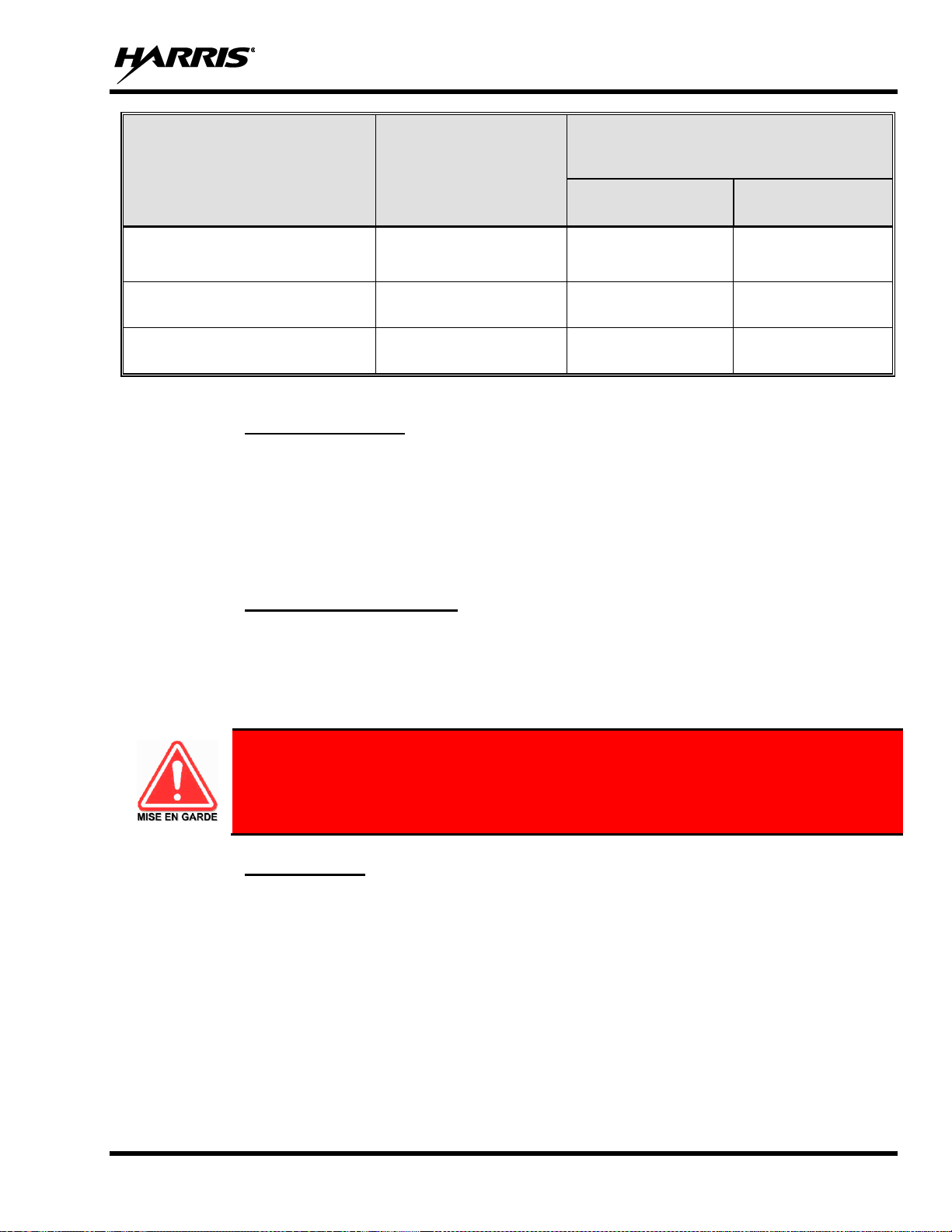
Table 1-1 lists the recommended minimum safe lateral distances for a controlled environment
and for unaware bystanders in an uncontrolled environment, from transmitting antennas (i.e.,
monopoles over a ground plane, or dipoles) at rated radio power for mobile radios installed in
a vehicle. Transmit only when unaware bystanders are at least the uncontrolled recommended
minimum safe lateral distance away from the transmitting antenna.
Page 9
14221-1850-2000
9
The XL Series mobile radio complies with the following RF energy exposure standards and guidelines:
• United States Federal Communications Commission (FCC), Code of Federal Regulations; 47 CFR § 2
sub-part J.
• American National Standards Institute (ANSI)/Institute of Electrical and Electronic Engineers (IEEE)
C95.1-2005.
• Institute of Electrical and Electronic Engineers (IEEE) C95.1-2005.
• IC Standard RSS-102, Issue 5, 2015: Spectrum Management and Telecommunications Radio Standards
Specification. Radio Frequency (RF) Exposure Compliance of Radiocommunication Apparatus (All
Frequency Bands).
Based on the highest radiated RF power and the highest antenna gain in antennas to be used with the XL
Series mobile radio, the distances listed are considered as safe distances for controlled and uncontrolled
environments with the XL Series mobile radio transmitting at a maximum 50% duty cycle.
1.3.1 Mobile Antennas
The antenna(s) for the radio must be installed in accordance with the antenna installation procedures
presented in the radio’s Installation Manual. Installation guidelines presented in the Installation Manual
are limited to metal-body motor vehicles or vehicles with appropriate ground planes.
Use only approved/supplied antenna(s) or an approved replacement antenna. Unauthorized antennas,
modifications, or attachments can cause the FCC RF exposure limits to be exceeded.
Table 1-1: Recommended Minimum Safe Lateral Distance from a
Transmitting Antenna Connected to an XL Mobile Radio
ANTENNA
PART NUMBERS
RF BAND
RECOMMENDED MINIMUM LATERAL
HUMAN BODY DISTANCE FROM
TRANSMITTING ANTENNA
CONTROLLED
ENVIRONMENT
UNCONTROLLED
ENVIRONMENT
12099-0370-01 (mount) with
12099-0300-01 (element)
700/800 MHz
7.9 inches
(20 centimeters)
19.7 inches
(50 centimeters)
AN-125001-002 (mount) with
12099-0310-01 (element)
700/800 MHz
7.9 inches
(20 centimeters)
19.7 inches
(50 centimeters)
AN-125001-004 (mount) with
12099-0310-01 (element)
700/800 MHz
7.9 inches
(20 centimeters)
19.7 inches
(50 centimeters)
AN-125001-006 (mount) with
12099-0310-01 (element)
700/800 MHz
7.9 inches
(20 centimeters)
19.7 inches
(50 centimeters)
AN-125001-008 (mount) with
12099-0310-01 (element)
700/800 MHz
7.9 inches
(20 centimeters)
19.7 inches
(50 centimeters)
12099-0370-01 (mount) with
12099-0310-01 (element)
700/800 MHz
7.9 inches
(20 centimeters)
19.7 inches
(50 centimeters)
AN-125001-002 (mount) with
AN-225001-001 (element)
700/800 MHz
7.9 inches
(20 centimeters)
19.7 inches
(50 centimeters)
AN-125001-004 (mount) with
AN-225001-001 (element)
700/800 MHz
7.9 inches
(20 centimeters)
19.7 inches
(50 centimeters)
Page 10

14221-1850-2000
10
ANTENNA
PART NUMBERS
RF BAND
RECOMMENDED MINIMUM LATERAL
HUMAN BODY DISTANCE FROM
TRANSMITTING ANTENNA
CONTROLLED
ENVIRONMENT
UNCONTROLLED
ENVIRONMENT
AN-125001-006 (mount) with
AN-225001-001 (element)
700/800 MHz
7.9 inches
(20 centimeters)
19.7 inches
(50 centimeters)
AN-125001-008 (mount) with
AN-225001-001 (element)
700/800 MHz
7.9 inches
(20 centimeters)
19.7 inches
(50 centimeters)
12099-0370-01 (mount) with
AN-225001-001 (element)
700/800 MHz
7.9 inches
(20 centimeters)
19.7 inches
(50 centimeters)
AN-125001-002 (mount) with
AN-225005-001 (element)
900 MHz
7.9 inches
(20 centimeters)
19.7 inches
(50 centimeters)
AN-125001-004 (mount) with
AN-225005-001 (element)
900 MHz
7.9 inches
(20 centimeters)
19.7 inches
(50 centimeters)
AN-125001-006 (mount) with
AN-225005-001 (element)
900 MHz
7.9 inches
(20 centimeters)
19.7 inches
(50 centimeters)
AN-125001-008 (mount) with
AN-225005-001 (element)
900 MHz
7.9 inches
(20 centimeters)
19.7 inches
(50 centimeters)
12099-0370-01 (mount) with
AN-225005-001 (element)
900 MHz
7.9 inches
(20 centimeters)
19.7 inches
(50 centimeters)
AN-125001-002 (mount) with
12099-0380-01 (element)
900 MHz
7.9 inches
(20 centimeters)
19.7 inches
(50 centimeters)
AN-125001-004 (mount) with
12099-0380-01 (element)
900 MHz
7.9 inches
(20 centimeters)
19.7 inches
(50 centimeters)
AN-125001-006 (mount) with
12099-0380-01 (element)
900 MHz
7.9 inches
(20 centimeters)
19.7 inches
(50 centimeters)
AN-125001-008 (mount) with
12099-0380-01 (element)
900 MHz
7.9 inches
(20 centimeters)
19.7 inches
(50 centimeters)
12099-0370-01 (mount) with
12099-0380-01 (element)
900 MHz
7.9 inches
(20 centimeters)
19.7 inches
(50 centimeters)
1.3.2 Approved Accessories
The radio has been tested and meets FCC RF guidelines when used with accessories supplied or designated
for use with it. Use of other accessories may not ensure compliance with the FCC’s RF exposure guidelines,
and may violate FCC regulations. For a list of approved accessories, refer to the radio’s Installation Manual
and/or the Products and Services Catalog.
1.3.3 Contact Information
For additional information on RF exposure and other information, contact Harris using one of the contact
links listed in Section 10.
Page 11

14221-1850-2000
11
1.4 REGULATORY APPROVALS
1.4.1 Applicable Type Acceptance/Certification Numbers
FCC Type Acceptance:
XL-185M: OWDTR-0160-E
Applicable FCC Rules: Part 15, FCC (ISED), Part 90 (RS-119)
Industry Canada Certification:
XL-185M: 3636B-0160
Applicable Industry Canada Rules: 24D (RSS-119), 15.247 (RSS-247), 15.407 (RSS-247),
15B (ICES-003 Issue 6)
1.4.2 FCC Part 15
This device complies with Part 15 of the FCC Rules. Operation is subject to the following two conditions:
1. This device may not cause harmful interference, and
2. This device must accept any interference received, including interference that may cause undesired
operation.
1.4.3 Industry Canada
This device complies with Industry Canada license-exempt RSS standard(s). Operation is subject to the
following two conditions: (1) this device may not cause interference, and (2) this device must accept any
interference, including interference that may cause undesired operation of the device.
Le présent appareil est conforme aux CNR d'Industrie Canada applicables aux appareils radio exempts de
licence. L'exploitation est autorisée aux deux conditions suivantes : (1) l'appareil ne doit pas produire de
brouillage, et (2) l'utilisateur de l'appareil doit accepter tout brouillage radioélectrique subi, même si le
brouillage est susceptible d'en compromettre le fonctionnement.
1.5 OCCUPATIONAL SAFETY GUIDELINES AND SAFETY TRAINING
INFORMATION
To ensure bodily exposure to RF electromagnetic energy is within the FCC allowable limits for
occupational use. Always adhere to the following basic guidelines:
• The push-to-talk button should only be depressed when intending to send a voice message.
• The radio should only be used for necessary work-related communications.
• The radio should only be used by authorized and trained personnel. It should never be operated by
children.
• Do not attempt any unauthorized modification to the radio. Changes or modifications to the radio may
cause harmful interference and/or cause it to exceed FCC RF exposure limits. Only qualified personnel
should service the radio.
• Always use only authorized accessories (antennas, control heads, speakers/mics, etc.). Use of
unauthorized accessories can cause the FCC RF exposure compliance requirements to be exceeded.
The information listed above provides the user with information needed to make him or her aware of a RF
exposure, and what to do to assure that this radio operates within the FCC exposure limits of this radio.
Page 12

14221-1850-2000
12
1.6 COMMON HAZARDS
The operator of any mobile radio should be aware of certain hazards common to the
operation of vehicular radio transmissions. Possible hazards include but are not limited to
the following:
• Explosive Atmospheres - Just as it is dangerous to fuel a vehicle while its engine is running, be sure
to turn the radio OFF while fueling the vehicle. If the radio is mounted in the trunk of the vehicle, DO
NOT carry containers of fuel in the trunk.
Areas with potentially explosive atmosphere are often, but not always, clearly marked. Turn the radio
OFF when in any area with a potentially explosive atmosphere. It is rare, but not impossible that the
radio or its accessories could generate sparks.
• Interference To Vehicular Electronic Systems - Electronic fuel injection systems, electronic anti-
skid braking systems, electronic cruise control systems, etc., are typical of the types of electronic
devices that can malfunction due to the lack of protection from radio frequency (RF) energy present
when transmitting. If the vehicle contains such equipment, consult the dealer for the make of vehicle
and enlist his aid in determining if such electronic circuits perform normally when the radio is
transmitting.
• Electric Blasting Caps - To prevent accidental detonation of electric blasting caps, DO NOT use two-
way radios within 1000 feet (305 meters) of blasting operations. Always obey the “Turn Off TwoWay Radios” (or equivalent) signs posted where electric blasting caps are being used. (OSHA
Standard: 1926.900).
• Radio Frequency Energy - To prevent burns or related physical injury from radio frequency energy,
do not operate the transmitter when anyone outside of the vehicle is within the minimum safe distance
from the antenna as specified in Table 1-1. Refer to Section 1.2 for additional information.
• Vehicles Powered by Liquefied Petroleum (LP) Gas - Radio installation in vehicles powered by
liquefied petroleum gas, where the LP gas container is in the trunk or other sealed-off space within the
interior of the vehicle, must conform to the National Fire Protection Association standard NFPA 58.
This requires:
➢ The space containing the radio equipment must be isolated by a seal from the space containing
the LP gas container and its fittings.
➢ Outside filling connections must be used for the LP gas container.
➢ The LP gas container space shall be vented to the outside of the vehicle.
• Vehicles Equipped with Airbags - For driver and passenger safety, avoid mounting the radio’s control
head (or any other component) above or near airbag deployment areas. In addition to driver-side and
passenger-side front-impact airbags, some vehicles may also be equipped with side-impact airbags. For
occupant safety, verify the location of all airbags within the vehicle before installing the radio
equipment.
Page 13

14221-1850-2000
13
1.7 SAFE DRIVING RECOMMENDATIONS
The American Automobile Association (AAA) advocates the following key safe driving recommendations:
• Read the literature on the safe operation of the radio.
• Keep both hands on the steering wheel and the microphone in its hanger whenever the vehicle is in motion.
• Place calls only when the vehicle is stopped.
• When talking from a moving vehicle is unavoidable, drive in the slower lane. Keep conversations brief.
• If a conversation requires taking notes or complex thought, stop the vehicle in a safe place and continue
the call.
• Whenever using a mobile radio, exercise caution.
1.8 OPERATING RULES AND REGULATIONS
Two-way radio systems must be operated in accordance with the rules and regulations of the local, regional,
or national government.
In the United States, the XL mobile radio must be operated in accordance with the rules and regulations of
the Federal Communications Commission (FCC). Operators of two-way radio equipment must be
thoroughly familiar with the rules that apply to the particular type of radio operation. Following these rules
helps eliminate confusion, assures the most efficient use of the existing radio channels, and results in a
smoothly functioning radio network.
When using a two-way radio, remember these rules:
• It is a violation of FCC rules to interrupt any distress or emergency message. The radio operates in
much the same way as a telephone “party line.” Therefore, always listen to make sure the channel is
clear before transmitting. Emergency calls have priority over all other messages. If someone is sending
an emergency message – such as reporting a fire or asking for help in an accident, do not transmit unless
assistance can be offered.
• The use of profane or obscene language is prohibited by Federal law.
• It is against the law to send false call letters or false distress or emergency messages. The FCC requires
keeping conversations brief and confined to business. Use coded messages whenever possible to save
time.
• Using the radio to send personal messages (except in an emergency) is a violation of FCC rules. Send
only essential messages.
• It is against Federal law to repeat or otherwise make known anything overheard on the radio.
Conversations between others sharing the channel must be regarded as confidential.
• The FCC requires self-identification at certain specific times by means of call letters. Refer to the rules
that apply to the particular type of operation for the proper procedure.
• No changes or adjustments shall be made to the equipment except by an authorized or certified
electronics technician.
Page 14
14221-1850-2000
14
Under U.S. law, operation of an unlicensed radio transmitter within the jurisdiction of the
United States may be punishable by a fine of up to $10,000, imprisonment for up to two (2)
years, or both.
1.9 OPERATING TIPS
The following conditions tend to reduce the effective range of two-way radios and should be avoided
whenever possible:
• Operating the radio in areas of low terrain, or while under power lines or bridges.
• Obstructions such as mountains and buildings.
In areas where transmission or reception is poor, communication improvement may sometimes
be obtained by moving a few yards in another direction, or moving to a higher elevation.
NOTE
Page 15
14221-1850-2000
15
2. RENSEIGNEMENTS SUR LA RÉGLEMENTATION ET
SÉCURITÉ
2.1 CONVENTIONS SUR LES SYMBOLES DE SÉCURITÉ
Les conventions suivantes sont utilisées dans le présent manuel pour avertir l’utilisateur des précautions
générales de sécurité qui doivent être observées pendant toutes les phases d’opération, d’entretien et de
réparation de ce produit. Le non-r.espect de ces précautions ou d’avertissements précisés ailleurs enfreint
les normes de sécurité de la conception, de la fabrication et de l’utilisation prévue du produit. Harris
n’assume aucune responsabilité pour le non-respect de ces normes par le client.
Le symbole MISE EN GARDE attire l’attention sur une procédure ou une pratique qui, si
elle n’est pas correctement effectuée ou observée, pourrait entraîner une blessure
personnelle. Ne pas poursuivre au-delà d’un symbole de MISE EN GARDE avant que les
conditions identifiées soient complètement comprises ou satisfaites.
Le symbole AVERTISSEMENT attire l’attention sur une procédure ou une pratique
opérationnelle qui, si elle n’est pas correctement effectuée ou observée, pourrait entraîner un bris
d’équipement ou une importante baisse de rendement de l’équipement.
Le symbole REMARQUE attire l’attention sur des renseignements supplémentaires qui peuvent
améliorer le rendement du système ou clarifier un processus ou une procédure.
2.2 RENSEIGNEMENTS SUR UNE EXPOSITION À L’ÉNERGIE DES RF
2.2.1 Renseignements Sur Le Contrôle Et La Sensibilisation À L’énergie Des
RF Pour Les Exigences D’une Utilisation Professionnelle De La FCC
Avant d’utiliser les radios mobiles bidirectionnelles, passez en revue les renseignements et les
instructions opérationnelles importants suivants sur le contrôle et la sensibilisation à l’énergie des
RF. Se conformer à ces renseignements et instructions pour assurer la conformité aux directives
d’exposition aux RF.
Cette radio est destinée à être utilisée dans des conditions professionnelles/
contrôlées, où les utilisateurs ont une pleine connaissance de leur exposition et peuvent
exercer un contrôle sur leur exposition pour rester sous les limites d’exposition aux RF.
Cette radio N’est PAS autorisée pour la population générale, les consommateurs ou toute
autre utilisation.
Page 16

14221-1850-2000
16
Des changements ou modifications non expressément approuvés par Harris pourraient
annuler le droit d’utilisation de l’équipement pour l’utilisateur.
Cette radio bidirectionnelle utilise une énergie électromagnétique dans le spectre des radiofréquences (RF)
pour permettre une communication à distance entre deux utilisateurs ou plus. Elle utilise l’énergie des RF
ou les ondes radio pour envoyer et recevoir des appels. L’énergie des RF est une forme d’énergie
électromagnétique. D’autres formes comprennent, entre autres, l’énergie électrique, la lumière du soleil et
les rayons X. Toutefois, l’énergie des RF ne doit pas être confondue avec ces autres formes d’énergie
électromagnétique qui, lorsque mal utilisées, peuvent causer des dommages biologiques. Par exemple, des
niveaux très élevés de rayons X peuvent endommager les tissus et le matériel génétique.
Des experts en science, en ingénierie, en médecine, en santé et de l’industrie travaillent avec des organismes
pour établir des normes pour l’exposition à l’énergie des RF. Ces normes procurent des niveaux
recommandés d’exposition aux RF autant aux travailleurs qu’au grand public. Ces niveaux d’exposition
aux RF recommandés comprennent d’importantes marges de protection. Toutes les radios bidirectionnelles
commercialisées en Amérique du Nord sont conçues, fabriquées et testées pour s’assurer qu’elles satisfont
les niveaux d’exposition aux RF établis par le gouvernement. Les fabricants recommandent également des
consignes d’utilisation particulières aux utilisateurs de radios bidirectionnelles. Ces instructions sont
importantes, car elles informent les utilisateurs sur l’exposition à l’énergie des RF et donnent des procédures
simples sur la manière de contrôler cette exposition. Consultez les sites Web suivants (en anglais) pour de
plus amples renseignements sur ce qu’est l’exposition à l’énergie des RF et comment contrôler l’exposition
pour assurer la conformité aux limites d’exposition établies :
http://www.fcc.gov/oet/rfsafety/rf-faqs.html
http://www.osha.gov./SLTC/radiofrequencyradiation/index.html
2.2.2 Règlements de la Federal Communications Commission (« Commission
fédérale des communications » aux États-Unis)
Avant d’être mise sur le marché aux États-Unis, la radio mobile bidirectionnelle XL a été testée pour
s’assurer de sa conformité aux limites d’exposition à l’énergie des RF de la FCC pour les radios mobiles
bidirectionnelles. Lorsque les radios bidirectionnelles sont utilisées à la suite d’une embauche, la FCC
demande aux utilisateurs de bien connaître et de pouvoir contrôler leur exposition pour satisfaire les
exigences professionnelles. La sensibilisation à l’exposition peut être facilitée par l’utilisation d’une
étiquette qui dirige les utilisateurs vers des renseignements particuliers sur la sensibilisation de l’utilisateur.
La radio possède une étiquette de produit sur l’exposition aux RF. De plus, le Manuel sur la sécurité du
produit et le présent Manuel de l’opérateur comprennent des renseignements et les consignes d’utilisation
nécessaires pour contrôler l’exposition aux RF et pour satisfaire les exigences de conformité.
d’utilisation nécessaires pour contrôler l’exposition aux RF et pour satisfaire les exigences de conformité.
Page 17

14221-1850-2000
17
2.3 CONFORMITÉ AUX NORMES D’EXPOSITION AUX RF
La radio mobile bidirectionnelle XL est conçue et testée pour être conforme à un certain nombre de normes
et directives nationales et internationales quant à l’exposition humaine à l’énergie électromagnétique des
RF. Cette radio est conforme aux limites d’exposition de l’IEEE et de la Commission internationale de
protection contre les rayonnements non ionisants pour un environnement professionnel/contrôlé
d’exposition aux RF à des périodes de cycle de service allant jusqu’à 50 % (50 % de transmission, 50 % de
réception) et elle est autorisée par la FCC pour une utilisation professionnelle. Sur le plan de la mesure de
l’énergie des RF pour la conformité aux directives d’exposition de la FCC, l’antenne de la radio irradie une
énergie des RF mesurable seulement lorsqu’elle transmet (parler), et non lorsqu’elle reçoit (écouter) ou en
mode d’attente.
Tableau 2-1 indiquent les distances latérales sécuritaires minimales recommandées pour un
environnement contrôlé et pour les spectateurs ignorants dans un environnement non contrôlé,
d’antennes de transmission (c.-à-d., des monopôles sur un plan de sol, ou des dipôles) à une
puissance de radio évaluée pour les radios mobiles installées dans un véhicule. Ils ne transmettent
que lorsque les spectateurs ignorants sont au moins à la distance latérale sécuritaire minimale
recommandée non contrôlée de l’antenne de transmission.
La radio mobile bidirectionnelle XL est conforme aux normes et directives d’exposition à l’énergie des RF
suivantes :
• Federal Communications Commission (FCC) américaine, le Code of Federal Regulations; 47 CFR § 2
sous-partie J.
• American National Standards Institute (ANSI)/Institute of Electrical and Electronic Engineers (IEEE)
C95.1-2005.
• Institute of Electrical and Electronic Engineers (IEEE) C95.1-2005.
• IC Standard RSS-102, numéro 5, 2015: Spectrum Management and Telecommunications Radio
Standards Specification. Radiofrequency Exposure Compliance of Radiocommunication Apparatus
(All Frequency Bands).
Basées sur la puissance des RF irradiées la plus élevée et le gain d’antenne le plus élevé dans les antennes
à utiliser avec le radio mobile bidirectionnelle XL, les distances indiquées dans les Tableau 2-1 sont
considérées comme des distances sécuritaires pour des environnements contrôlés et non contrôlés avec la
radio mobile XL qui transmet à un cycle de service maximal de 50 % :
Page 18

14221-1850-2000
18
Tableau 2-1: Distance latérale sécuritaire minimale recommandée d’une antenne de transmission branchée
sur une radio mobile XL
NUMÉRO DE PIÈCE DE
L’ÉLÉMENT DE L’ANTENNE
DESCRIPTION DE
L’ANTENNE
DISTANCE MINIMALE RECOMMANDÉE
DE L’ANTENNE DE TRANSMISSION
POUR LE CORPS HUMAIN
ENVIRONNEMENT
CONTRÔLÉ
ENVIRONNEMENT
NON CONTRÔLÉ
12099-0370-01 (monture) avec
12099-0300-01 (élément)
700/800 MHz
20 centimeters
(7.9 po)
50 centimeters
(19.7 po)
AN-125001-002 (monture) avec
12099-0310-01 (élément)
700/800 MHz
20 centimeters
(7.9 po)
50 centimeters
(19.7 po)
AN-125001-004 (monture) avec
12099-0310-01 (élément)
700/800 MHz
20 centimeters
(7.9 po)
50 centimeters
(19.7 po)
AN-125001-006 (monture) avec
12099-0310-01 (élément)
700/800 MHz
20 centimeters
(7.9 po)
50 centimeters
(19.7 po)
AN-125001-008 (monture) avec
12099-0310-01 (élément)
700/800 MHz
20 centimeters
(7.9 po)
50 centimeters
(19.7 po)
12099-0370-01 (monture) avec
12099-0310-01 (élément)
700/800 MHz
20 centimeters
(7.9 po)
50 centimeters
(19.7 po)
AN-125001-002 (monture) avec
AN-225001-001 (élément)
700/800 MHz
20 centimeters
(7.9 po)
50 centimeters
(19.7 po)
AN-125001-004 (monture) avec
AN-225001-001 (élément)
700/800 MHz
20 centimeters
(7.9 po)
50 centimeters
(19.7 po)
AN-125001-006 (monture) avec
AN-225001-001 (élément)
700/800 MHz
20 centimeters
(7.9 po)
50 centimeters
(19.7 po)
AN-125001-008 (monture) avec
AN-225001-001 (élément)
700/800 MHz
20 centimeters
(7.9 po)
50 centimeters
(19.7 po)
12099-0370-01 (monture) avec
AN-225001-001 (élément)
700/800 MHz
20 centimeters
(7.9 po)
50 centimeters
(19.7 po)
AN-125001-002 (monture) avec
AN-225005-001 (élément)
900 MHz
20 centimeters
(7.9 po)
50 centimeters
(19.7 po)
AN-125001-004 (monture) avec
AN-225005-001 (élément)
900 MHz
20 centimeters
(7.9 po)
50 centimeters
(19.7 po)
AN-125001-006 (monture) avec
AN-225005-001 (élément)
900 MHz
20 centimeters
(7.9 po)
50 centimeters
(19.7 po)
AN-125001-008 (monture) avec
AN-225005-001 (élément)
900 MHz
20 centimeters
(7.9 po)
50 centimeters
(19.7 po)
12099-0370-01 (monture) avec
AN-225005-001 (élément)
900 MHz
20 centimeters
(7.9 po)
50 centimeters
(19.7 po)
AN-125001-002 (monture) avec
12099-0380-01 (élément)
900 MHz
20 centimeters
(7.9 po)
50 centimeters
(19.7 po)
AN-125001-004 (monture) avec
12099-0380-01 (élément)
900 MHz
20 centimeters
(7.9 po)
50 centimeters
(19.7 po)
Page 19
14221-1850-2000
19
NUMÉRO DE PIÈCE DE
L’ÉLÉMENT DE L’ANTENNE
DESCRIPTION DE
L’ANTENNE
DISTANCE MINIMALE RECOMMANDÉE
DE L’ANTENNE DE TRANSMISSION
POUR LE CORPS HUMAIN
ENVIRONNEMENT
CONTRÔLÉ
ENVIRONNEMENT
NON CONTRÔLÉ
AN-125001-006 (monture) avec
12099-0380-01 (élément)
900 MHz
20 centimeters
(7.9 po)
50 centimeters
(19.7 po)
AN-125001-008 (monture) avec
12099-0380-01 (élément)
900 MHz
20 centimeters
(7.9 po)
50 centimeters
(19.7 po)
12099-0370-01 (monture) avec
12099-0380-01 (élément)
900 MHz
20 centimeters
(7.9 po)
50 centimeters
(19.7 po)
2.3.1 Antennes Mobiles
Les antennes pour la radio doivent être installées conformément aux procédures présentées dans le Manuel
sur la sécurité du produit et dans le Manuel d’installation. L’installation est limitée à un ou des véhicules
motorisés en métal avec des plans au sol appropriés.
Utilisez uniquement les antennes approuvées/fournies ou une antenne de remplacement approuvée. Des
antennes, des modifications ou des accessoires non autorisés peuvent causer un dépassement des limites
d’exposition aux RF de la FCC.
2.3.2 Accessoires Approuvés
La radio a été testée et satisfait les directives de RF de la FCC lorsqu’elle est utilisée avec les accessoires
fournis ou conçus pour être utilisés avec elle. L’utilisation d’autres accessoires peut ne pas garantir la
conformité aux directives d’exposition de la FCC et peut enfreindre la réglementation de la FCC. Pour une
liste d’accessoires approuvés, consultez le Manuel d’installation ou le Catalogue de produits et services de
Harris.
Utilisez toujours des accessoires autorisés Harris (antennes, haut-parleurs/micros, etc.).
L’utilisation d’accessoires non autorisés peut entraîner un dépassement des exigences de
conformité pour une exposition aux RF professionnelle ou contrôlée de la FCC.
2.3.3 Coordonnées
Pour de plus amples renseignements sur l’exposition aux RF ou d’autres renseignements, contactez Harris
en utilisant l’un des liens apparaissant à la Section 10.
Page 20

14221-1850-2000
20
2.4 INTERFÉRENCE DES RADIOFRÉQUENCES
2.4.1 Partie 15 de la FCC
Cet appareil est conforme à la Partie 15 de la réglementation de la FCC. Le fonctionnement est soumis aux
deux conditions suivantes :
1. Cet appareil ne doit pas causer une interférence nuisible; et
2. Cet appareil doit accepter toute interférence reçue, y compris une interférence qui peut causer un
fonctionnement non souhaité.
2.4.2 Industrie Canada
Cet appareil est conforme aux normes RSS exemptées de licence d’Industrie Canada. Le fonctionnement
est soumis aux deux conditions suivantes : (1) cet appareil ne doit pas causer d’interférence et (2) cet
appareil doit accepter toute interférence, y compris une interférence qui peut causer un fonctionnement non
souhaité de l’appareil.
2.5 RENSEIGNEMENTS SUR LA FORMATION SUR LA SANTÉ ET LA
SÉCURITÉ AU TRAVAIL
S’assurer que l’exposition physique à l’énergie électromagnétique des RF se situe dans les limites
acceptables de la FCC pour l’utilisation professionnelle. Toujours se conformer aux directives de base
suivantes :
• Le bouton de microphone doit être abaissé seulement lorsque l’on souhaite envoyer un message vocal.
• La radio doit être utilisée seulement pour les communications nécessaires liées au travail.
• La radio doit être utilisée seulement par du personnel autorisé et formé. Elle ne doit jamais être utilisée
par des enfants.
• Ne tentez pas d’apporter une modification non autorisée à la radio. Des changements ou des
modifications à la radio peuvent causer une interférence nocive ou entraîner un dépassement des limites
d’exposition aux RF de la FCC. Seul le personnel qualifié doit utiliser la radio.
• Utilisez toujours seulement des accessoires autorisés (antennes, haut-parleurs/micros, etc.).
L’utilisation d’accessoires non autorisés peut entraîner un dépassement des exigences de conformité
pour une exposition aux RF de la FCC.
Les renseignements donnés ci-dessus donnent à l’utilisateur les renseignements nécessaires pour le
sensibiliser à l’exposition aux RF et sur ce qu’il faut faire pour s’assurer que cette radio fonctionne dans les
limites d’exposition de la FCC de cette radio.
Page 21
14221-1850-2000
21
3. INTRODUCTION
3.1 DESCRIPTION
The XL Series mobile radio provides the advanced connectivity that first responders require while
addressing evolving voice and data communications. It meets MIL-STD-810G for durability. XL Mobile
radios support P25 Trunking, P25 Conventional, and analog conventional.
The XL Mobile is a P25 converged, multiband Land Mobile Radio with an option to include LTE capability.
Designed for anyone who needs to communicate with multiple agencies or across multiple bands, the XL
Mobile delivers mission-critical connectivity.
For options and accessories, refer to Section 3.3. Additional accessories may have been added since
publication of this manual; contact Harris for more information.
The XL Mobile installation includes a control head and the Vehicle Communications Hub (VCH), which
are described in the following sections.
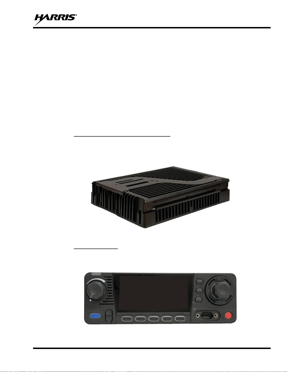
3.1.1 Vehicle Communications Hub (VCH)
The XL Vehicle Communications Hub (VCH) is the main LMR radio unit in a vehicular (mobile) radio
system. A major feature of the VCH design is the use of IP networks for tethering multiple radio control
heads. With respect to the audio systems, this feature allows the VCH to support approximately eight IP
devices as audio sources and destinations.
Figure 3-1: Vehicle Communications Hub (VCH)
3.1.2 XL Control Head
The XL Mobile supports the addition of an XL control head to the VCH in a front mount or remote mount
configuration. In the front mount configuration, the VCH and control head are physically mounted together,
while in the remote mount configuration, the control head is located in a separate location.
Figure 3-2: XL Control Head
Page 22

14221-1850-2000
22
The XL Control Head is a networked device that uses a wired Ethernet connection to provide remote control
of the VCH. It includes a color LCD graphical user interface and physical knobs and buttons to allow a user
to view status and control other devices. The control head also provides multiple audio interfaces to capture
and play real-time audio.
The XL Control Head’s mission-critical design provides a tactile interface optimized for tactile operation.
Controls and display are laid out to give instant access to primary use cases.
Standard Control Head Features include:
• Wi-Fi (802.11B, G, N)
• Bluetooth 4.0
• Built-in Speaker
• Hi-visibility Color Display
3.2 CLEANING
Keep the exterior of the radio equipment clean. This includes the radio, control head, microphone, and
speaker. Periodically clean them using either the Light-duty cleaning procedure or in extreme cases the
Heavy-duty cleaning procedure as described in the maintenance manual.
Page 23
14221-1850-2000
23
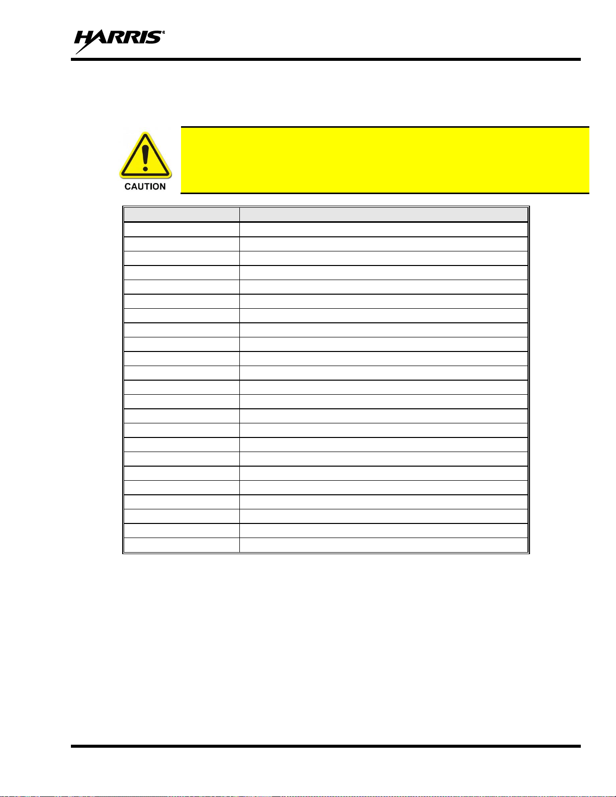
3.3 OPTIONS AND ACCESSORIES
Only use Harris approved accessories. Refer to Harris’ Product and Services catalog for the complete list
of options and accessories available.
Always use the correct options and accessories for the radio.
PART NUMBER
DESCRIPTION
XM-AN7G
USB Mobile Mic
XMAN6H
Remote Speaker
AN-125001-002
Analog Deskmic
AN-125001-004
CH mounting kit
AN-125001-006
VCH mounting kit
12099-0300-01
Antenna, Flex, Heavy-Duty, 136-870 MHz
12099-0310-01
Antenna, Element, Multiband, 136-870 MHz, 0 dB
AN-125001-002
Antenna, Base, Standard Roof Mount Low Loss
AN-125001-004
Antenna, Base, Thick Roof Mount Low Loss
AN-125001-006
Antenna, Base, Standard Roof Mount Low Loss GPS
AN-125001-008
Antenna, Base, Magnetic Mount Low Loss
12099-0370-01
Mount, NMO Antenna, Magnetic, Heavy-Duty
AN-225001-001
Antenna, Element, 700/800 3dB
AN-225005-001
Antenna, Element, 900, 3 dB
AN-025187-001
Antenna, GPS, Roof Mount
AN-025187-003
Antenna, GPS, Magnet Mount
AN-125001-006
Antenna, Base, Standard Roof Mount Low Loss GPS
12099-0380-01
Antenna 3 dB 700/800/900 MHz, 12099-0380-01
14002-0174-50
Squid cable (HD44)
14050-6300-01
Ethernet Cable, overmold, 45 cm
14050-6300-02
Ethernet Cable, overmold, 9 m
CA-012616-001
DC power cables (CH)
CA-012365-001
DC power cables (VCH)
Page 24

14221-1850-2000
24
3.4 RELATED PUBLICATIONS
The following publications contain additional information about the radio and related products:
MANUAL NUMBER
DESCRIPTION
14221-1850-2010
XL Mobile Product Safety Manual
14221-1850-1000
XL Mobile Quick Guide
14221-1850-4000
XL Mobile Installation Manual
14221-1850-5000
XL Mobile Maintenance Manual
14221-1800-8000
XLP Software Release Notes
MM1000019423
Key Manager and Key Admin Overview and Operation Manual
MM1000019424
Key Manager and Key Loader Overview and Operation Manual
14221-7200-6110
Voice Annunciation Feature Manual
14221-2100-3000
Advanced Access Control/Radio Personality Manager Overview Manual
14221-1100-8170
Radio Personality Manager 2 (RPM2) Software Release Notes
14221-1100-2060
RPM2 User’s Manual
14221-7200-6130
BeOn Configuration and Use Feature Manual
14221-7200-6140
Noise Cancellation Feature Manual
14221-1800-4000
Nano SIM Card Install/Replacement Accessory Kit Installation Manual
The product safety manual and the quick guide are included with the radio equipment package when the
radio ships from the factory. All publications listed above are available at www.pspc.harris.com via an
Information Center login and Tech-Link.
Page 25
14221-1850-2000
25
4. BASIC OPERATION
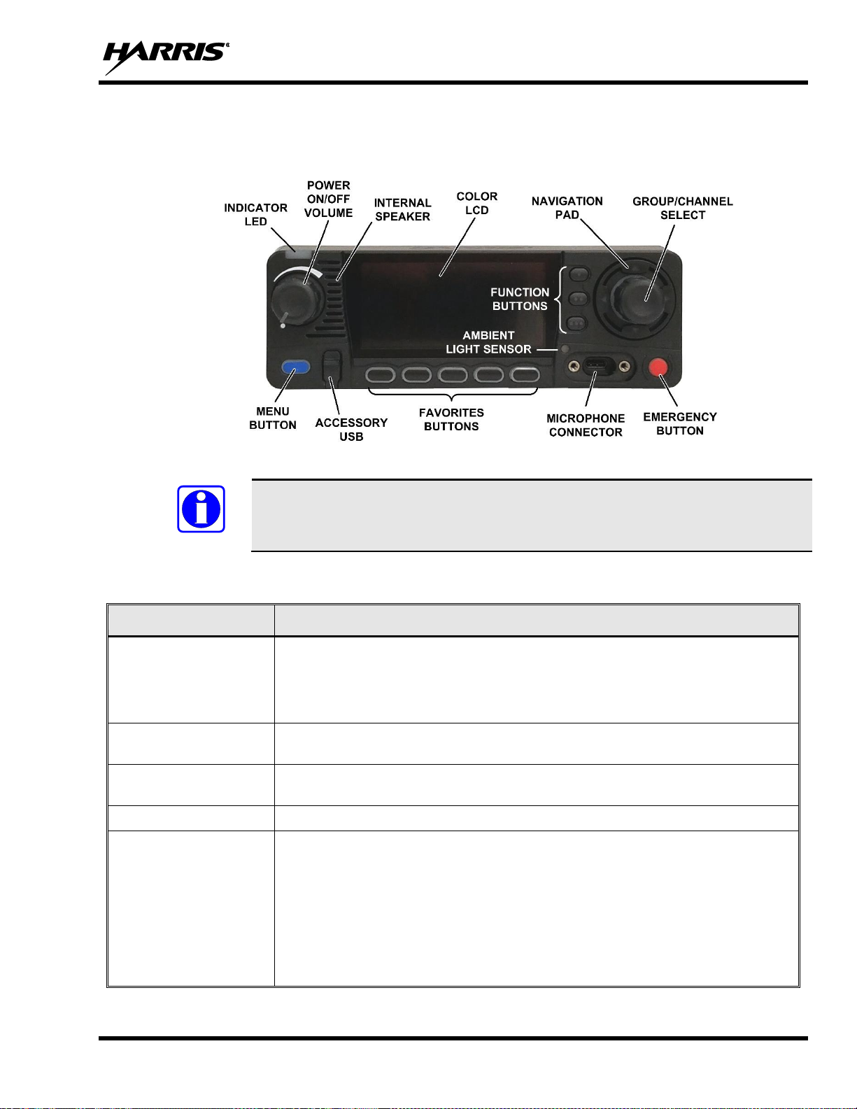
4.1 RADIO CONTROLS
Figure 4-1: Radio Controls
Table 4-1 describes the default functions of buttons, knobs, and controls. Some can be
programmed for different functions; see Section 6.4 for more information.
Table 4-1: Radio Controls, Indicators, and Connectors
CONTROL/INDICATOR
FUNCTION
Power On/Off
Volume Control
Turn knob clockwise to power on the radio and increase volume.
Turn counter-clockwise to decrease volume and power off the radio. Minimum
volume levels can be programmed into the radio to prevent missed calls due to a
low volume setting.
Group/Channel
Selection
Selects the available groups or channels.
Microphone
Connector
Connection for hand-held microphones.
Emergency Button
Declares an emergency.
Navigation Pad
Navigates menu items.
In addition:
• Press the left navigation button while on the idle display to access Channel
Information.
• Press the down navigation button while on the idle display to display the
functions assigned to programmable buttons.
• Press the up navigation button to display Missed Call info.
• Press the right navigation button to end or reject an I-Call.
NOTE
Page 26
14221-1850-2000
26
CONTROL/INDICATOR
FUNCTION
Menu Button
From the Main Display, press this button to access the menu. Press this button
while in a menu to return to the idle screen.
USB Connector
Connection for USB accessory (e.g., Programming Cable or USB accessory).
Function Buttons
Programmable dynamic keys that have their function labeled on the radio display
beside each button.
Favorites Buttons
User-programmable dynamic keys that can be assigned to a favorite Group or
Channel. Alternatively, the button may have a function assigned to it. The label
appears on the radio display above each button.
Indicator LED
Indicates radio status:
• Red = actively transmitting.
• Green = actively receiving.
• Orange = actively transmitting encrypted.
4.2 BEFORE FIRST USE
Make sure the XL Mobile has:
• Personality and radio programmed using RPM2
• Encryption keys loaded if using encrypted channels
• Personality activated
4.3 POWER ON AND SET VOLUME
The power switch and volume control are the same knob on the radio (see Figure 4-1). Turn the
Power/Volume Knob clockwise to power on radio and increase the volume.
A minimum volume level can be programmed into the radio to prevent missed calls due to
a low volume setting.
NOTE
Page 27
14221-1850-2000
27
4.4 USER LOGIN (VIDA PROVISIONING)
VIDA Provisioning provides the capability to provision the VIDA User Personality configured in the UAS
to VIDA units operating on P25 networks via a User Login. Each personality can contain up to 16 profiles
and each profile can contain up to sixteen Talk Groups.
User Login enables multiple radio users to pick a radio from a fleet pool and enter unique credentials to log
into the P25 system as themselves. Upon successful login, the Alias associated with the radio user is
displayed at various end points in the P25 system.
A user can login on up to three (3) devices simultaneously. For example, if the “same user” is logged into
a portable radio and mobile radio, the P25 system can differentiate the subscribers while transparently
displaying the alias to other users.
Login can be initiated by a menu option, a button programmed for user login, or by selecting a P25 system
that requires login. To login manually:
1. From the UTILITY radio menu, select USER LOGIN, or press the button programmed for User
Login.
2. Enter the System ID, User ID, and Password, as required.
3. Select Login.
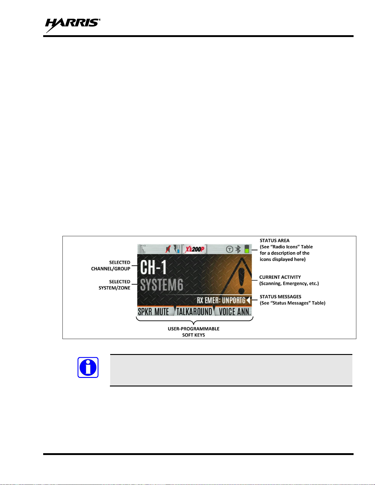
4.5 RADIO DISPLAYS
Figure 4-2 shows a sample front display while on the idle screen. The idle screen appears after power up
or after exiting from the menus.
Figure 4-2: Sample Idle Front Display
The radio can be programmed to display the User ID on the System line of the display.
NOTE
Page 28
14221-1850-2000
28
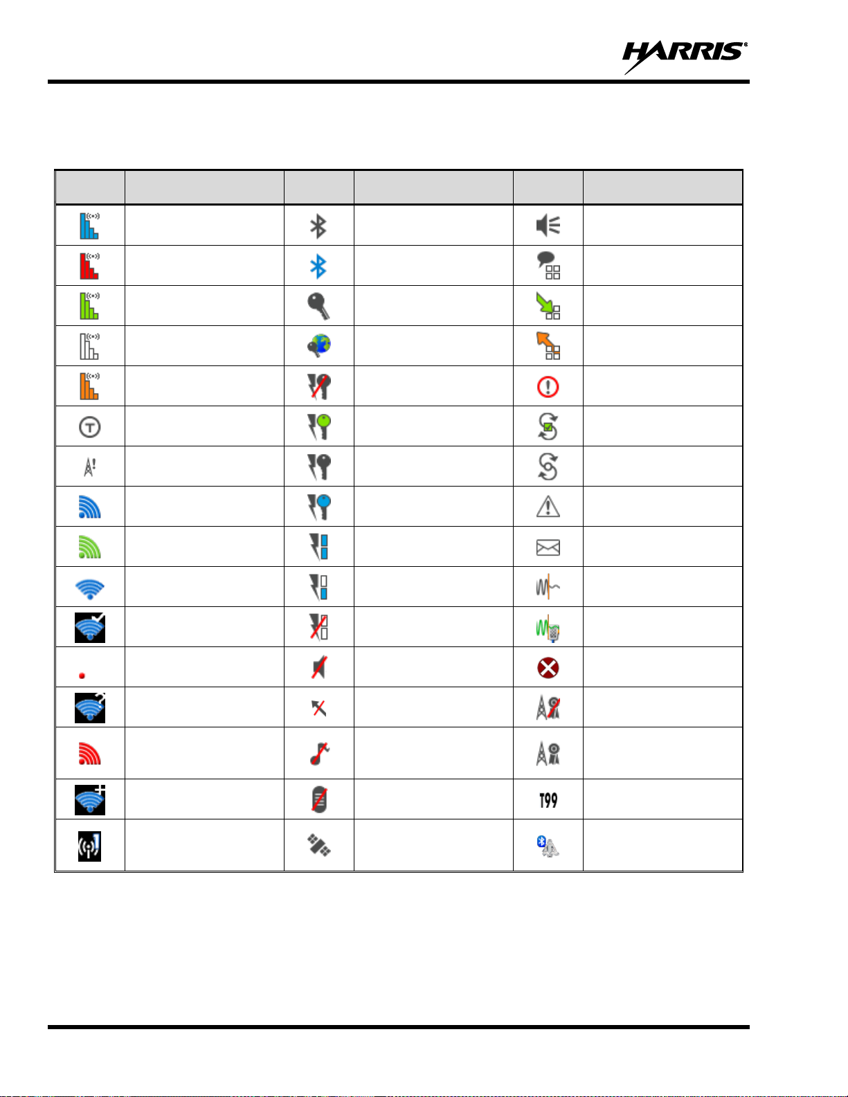
Table 4-2 describes some of the icons that may be displayed by the radio. The radio menu also contains an
icon glossary in the Utility Menu (see Section 4.7). Icons and their location can be customized using RPM2.
Table 4-2: Radio Icons
ICON
DESCRIPTION
ICON
DESCRIPTION
ICON
DESCRIPTION
(Blue)
Trunked Signal Strength
Bluetooth Enabled
Monitor On
(Red)
TX Power
(Blue)
Bluetooth Connected
VDOC
(Green)
Receive Signal Strength
Encryption Enabled
Receiving Data
(No Color)
Channel Idle
Global Encryption
Transmitting Data
(Orange)
Transmitting Encrypted
OTAR Disabled
Alert(s) Present
Talkaround Enabled
OTAR Registered
Vote Scanning
Failsoft
OTAR Registering
Scanning Enabled
LTE – Registered
Foreign Network
OTAR Rekeying
Emergency
LTE – Registered Home
Transmit Power Level
High
RX Mail
Wi-Fi Signal
Strength Indicator
Transmit Power Level
Low
Noise Cancellation
Enabled
Wi-Fi Network
Currently Connected
RX Only
Fire Speaker Mic
Attached
LTE – No Signal
Speaker Muted
Nuisance Channel
Wi-Fi Network in
Process of Connecting
TX Disabled
Conventional Site
Unregistered
LTE – Denied or
Unknown
Registration Status
Tones Disabled
Conventional Site
Registered
Add New Wi-Fi Client
PTT Disabled
Type 99 Enabled
Wi-Fi Clients Connected
GPS Tracking
A wearable Bluetooth
device is attached
(e.g., SCBA)
Page 29
14221-1850-2000
29
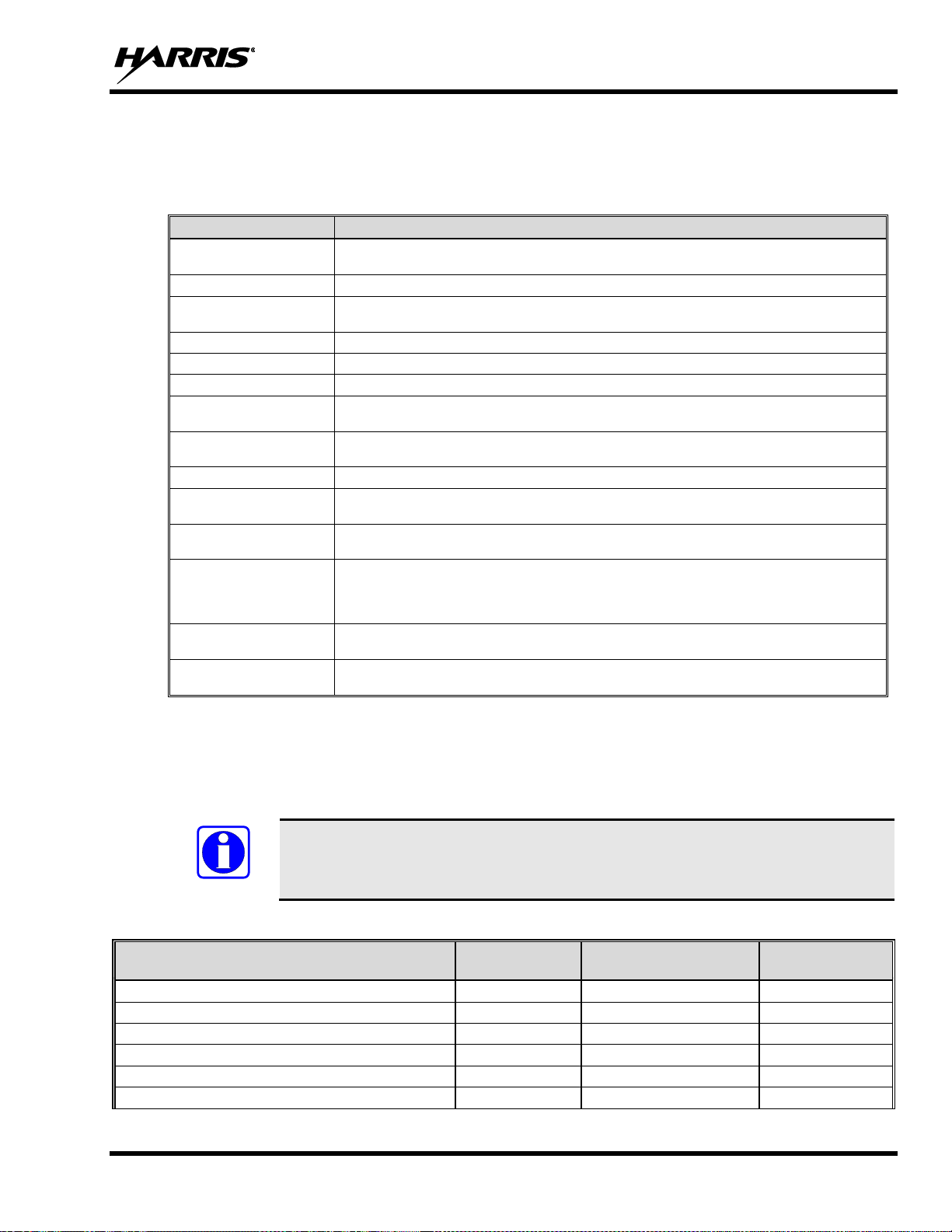
4.6 STATUS MESSSAGES
The radio may display various radio Status Messages during operation. These messages are described in
Table 4-3.
Table 4-3: Status Messages
MESSAGE
DESCRIPTION
PTT DENIED
P25 Trunked and EDACS - The radio or talkgroup is not authorized to operate on the selected
system and/or talkgroup.
CALL QUEUED
P25 Trunked and EDACS - The system has placed the call in a request queue.
SYSTEM BUSY
P25 Trunked and EDACS - The system is busy, no channels are currently available, the queue is
full, or an individual call is being attempted to a radio that is currently transmitting.
SCANNING
The radio is scanning.
TX EMERGENCY
An emergency call is being transmitted.
RX EMERGENCY
An emergency call is being received. The radio displays the unit name or unit ID.
WIDE AREA SCAN
P25 Trunked and EDACS - The radio has entered the Wide Area Scan mode to search for a new
system.
INVALID TALKGROUP
P25 Trunked and EDACS - The current talkgroup is not valid for the current system. This could
happen if the site denies registration due to an unrecognized talkgroup ID.
INVALID UNIT
P25 Trunked and EDACS - The current unit is not valid for the current system.
REGISTERING
P25 Trunked only - Displayed when the radio is performing a registration/affiliation on a P25
trunking site.
CTRL CHANNEL SCAN
P25 Trunked and EDACS - The control channel is lost and the radio has entered the Control
Channel Scan mode to search for the control channel (usually out of range indication).
BAND SCANNING
P25 Trunked - Only displayed if the system is configured for "EnhancedCC" mode of operation.
When the radio cannot find a Control Channel in either the trunked frequency set or the list of
discovered adjacencies, the radio can perform a full spectrum frequency scan to find a new
Control Channel.
MISSED CALL
P25 Modes and EDACS - Another user has tried to call or page this radio. The user can view
who the caller was by pressing the up navigation button.
OTAR REKEY
COMPLETE
OTAR Rekey operation completed successfully.
4.7 PREDEFINED MENU LAYOUTS
Depending on radio programming, some menu options described in this manual may not be available. The
radio supports three predefined menu layouts: Full, Custom, and Restricted. Table 4-4 details what is
available in each layout:
The Custom predefined menu layout allows the administrator to customize the list of
menu items that are available to the radio user. Table 4-4 lists the default settings.
Table 4-4: Predefined Menu Layouts
MENU
FULL
CUSTOM
(Default Settings)
RESTRICTED
Call Menu
Yes
Yes
Yes
Exit Emergency
Yes
Yes
Yes
Talkaround
Yes
Yes
Yes
Individual Call
Yes
Yes
Yes
Change Talkgroup
Yes
Yes
Yes
Call Alert/Page
Yes
Yes
Yes
NOTE
Page 30

14221-1850-2000
30
MENU
FULL
CUSTOM
(Default Settings)
RESTRICTED
Channel Guard
Yes
Yes
Yes
Audio Playback
Yes
Yes
No
Tone Encode
Yes
Yes
Yes
T99
Yes
Yes
Yes
Scan Menu
Yes
Yes
Yes
Enable/Disable Scan
Yes
Yes
Yes
View Scan List
Yes
Yes
No
Edit Zone Scan List
Yes
No
No
View Custom Channels
Yes
Yes
No
Edit Custom Scan List
Yes
No
No
Custom Scan
Yes
Yes
No
Site Roam
Yes
Yes
No
Site Alias
Yes
Yes
No
Security Menu
Yes
Yes
Yes
Encryption Enable
Yes
Yes
Yes
Zeroize
Yes
No
No
Global CKR Enable
Yes
No
No
GCKR Key Select
Yes
No
No
Active Key Set
Yes
Yes
Yes
Key List
Yes
Yes
No
OTAR Enable
Yes
Yes
No
OTAR Rekey
Yes
Yes
Yes
Message Menu
Yes
Yes
Yes
Radio Status
Yes
Yes
No
Radio Message
Yes
Yes
No
Textlink Messages
Yes
Yes
No
Textlink Forms
Yes
Yes
No
Textlink Mailbox
Yes
Yes
No
Faults
Yes
Yes
Yes
Audio Settings
Yes
No
No
Display Settings
Yes
Yes
Yes
Bluetooth Settings
Yes
Yes
No
Clock Settings
Yes
Yes
No
Program Menu
Yes
Yes
No
Activate Plan
Yes
Yes
No
Activate Profile
Yes
Yes
No
GPS Settings
Yes
No
No
Maintenance Menu
Yes
Yes
Yes
Radio Info
Yes
Yes
No
TCXO Tuning
Yes
No
No
P25 Tests
Yes
No
No
RSSI Display
Yes
Yes
Yes
Phase II Display
Yes
Yes
No
Feature Info
Yes
Yes
No
Change Language
Yes
No
No
Page 31

14221-1850-2000
31
MENU
FULL
CUSTOM
(Default Settings)
RESTRICTED
Change PIN
Yes
Yes
Yes
WiFi Access Point
Yes
Yes
Yes
WiFi Client
Yes
Yes
No
Install GPP Software x
Yes
Yes
Yes
Icon Glossary
Yes
Yes
Yes
Zone
Yes
Yes
No
LTE
Yes
Yes
No
4.8 MENU
Press the Menu/Select button while on the idle display to access the menu. Press the left or right navigation
buttons to scroll through the top-level menus, and press the up or down navigation buttons to scroll through
the sub-menus. Refer to Figure 4-1 for button location. While in a menu, press the Menu/Select button to
choose, activate, or toggle the selected item; similar to an enter key. Table 4-5 provides a high-level
overview of the menu layout.
Depending on radio programming, some menu options described in Table 4-5 may not be available. Three
predefined menu options are available: Full, Custom, and Restricted. Refer to the RPM2 online help for
what menu items are visible for each selection.
Page 32

14221-1850-2000
32
Table 4-5: Menu Navigation
MENUS
DESCRIPTION
CALL MENU:
EXIT EMERGENCY MODE
Exits emergency. See Section 4.28 for more information.
TALKAROUND MODE
Enable/disable talkaround. See Section 4.19 for more information.
TONE ENCODE
Analog conventional only - Transmits a programmed tone sequence on the current
radio system and channel. See Section 5.17 for more information.
INDIVIDUAL CALL
Allows you to select an individual for an individual call. See Section 4.13 for more
information.
PHONE CALL
Allows the user to initiate a telephone interconnect call. See Section 4.21 for more
information.
CHANGE TLKGRP
Change the selected talkgroup. See Section 4.12.
CALL ALERT
Select a group for Call Alert transmission. See Section 4.20.
CHANNEL GUARD
Select the Transmit and/or Receive Channel Guard tone. See Section 4.18.
AUDIO PLAYBACK
Replays the last recorded call. See Section 4.23 for more information.
SCAN MENU:
START SCAN/STOP SCAN
Start or stop scan operation. See Sections 4.24 and 4.25.
SCAN LISTS
View/Edit available scan lists. See Section 5.12.
ASSIGNED CUSTOM LIST
Create, View, and Edit Custom Scan Lists. See Section 5.12.6.
SITE ROAMING
Enable/Disable Wide Area System Scan. See Section 5.12.7.
SITE ALIAS
Select an available site from this list to lock the radio to; i.e., prevent the radio from
roaming. This is also known as Site Lock. See Section 5.12.8 for more
information.
SECURITY MENU:
ZEROIZE KEYS
Removes all encryption keys from the radio. See Section 5.18.2.
ENCRYPTION
Enable/Disable encryption. See Section 4.17.
GLOBAL ENCRYPTION
Enable/Disable Global Encryption. See Section 5.18.4.
GLOBAL KEY
Select the Global Key. Only available if Global Encryption is Enabled. See Section
5.18.4.
ACTIVE KEYSET
Select the Active Keyset. See Section 5.18.5.
KEY LIST
View available key lists. See Section 5.18.6.
OTAR
Enable/disable Over-the-Air Rekeying (OTAR). See Section 5.18.7.
OTAR REKEY
Request that the KMF updates the keys in the radio. See Section 5.18.7.
MESSAGES MENU:
RADIO STATUS
Used to send a status condition to the site without making a voice call. See
Section 5.12.8.
RADIO MESSAGE
Used to send a message to the site without making a voice call. See Section 5.14.
TEXTLINK MESSAGES
Allows the user to send a Radio TextLink message. See Section 5.15.
TEXTLINK FORMS
Allows the user to send a Radio TextLink form. See Section 5.15.
TEXTLINK MAILBOX
Contains received Radio TextLink messages. See Section 5.15.
FAULTS/ALERTS
Displays radio faults and alerts. See Section 5.16.
UTILITY MENU:
AUDIO SETTINGS:
• MASTER
Allows the user to enable or disable the master volume control. When enabled, it
allows remote control heads to control the volume of the speaker attached to the
back of the radio. When disabled, the volume knob on a remote mount control
head only controls the volume of the speaker attached to the control head.
• SPEAKER
Mute or unmute the speaker audio.
• NOISE CANCELLATION
Enable or disable Noise Cancellation. See Section 4.15.
• PTT
Enable or disable Push-To-Talk (PTT). Disable PTT to prevent accidental keying,
such as when radio is in the holster or you are getting into a car.
Page 33

14221-1850-2000
33
MENUS
DESCRIPTION
• TONES
Enable or disable radio side tones.
• KEYPAD TONES
Enable or disable tones that sound when the radio’s keypad buttons are pressed.
DISPLAY SETTINGS:
• COLOR SCHEME
Press the Menu/Select button to toggle the front and top display’s COLOR
SCHEME for optimum visibility in day or night conditions (NORMAL or
INVERTED).
• FRONT BACKLIGHT
Press the Menu/Select button to toggle the front display backlighting between
ON/OFF/MOMENTARY/MOMENTARY (OFF).
• FRONT BRIGHTNESS
Press the left or right navigation buttons to dim or brighten the display.
• FRONT TIMEOUT
When the FRONT BACKLIGHT setting is MOMENTARY, this value specifies how
long the radio needs to be inactive before the front display’s backlight turns off.
Press the left or right navigation buttons to change the time in 0.5 second
increments.
• FRONT DISPLAY OFF
Turns the front display off completely. Press the Menu/Select button to turn the
front display back on.
• DAY/NIGHT
Toggles between the Day and Night display modes.
• LEDs
Toggle indicator LEDs ON or OFF.
BLUETOOTH:
• ENABLED (YES/NO)
Enable/disable Bluetooth. See Section 5.9 for more information.
• DISCOVERABLE (YES/NO)
• VOLUME CONTROL (YES/NO)
If YES, the radio knob can be used to adjust Bluetooth speaker volume (if the
Bluetooth device supports it).
• BLUETOOTH SPEAKER
Mute/Unmute Bluetooth Speaker.
• EXTERNAL SPEAKER
Mute/Unmute External Speaker.
• PAIRING MGMT
Pair Bluetooth devices with the radio. See Section 5.9 for more information.
CLOCK SETTINGS:
• TIME FORMAT
Select 12 or 24-hour time display format.
• TIME ZONE
Set time zone relative to Universal Time Coordinated (UTC).
GPS SETTINGS:
• GPS (ENABLED/DISABLED)
Enable/disable GPS.
• POSITION INFO
Displays GPS, Latitude, Longitude, and Altitude information. From this menu, click
NEXT to access SA INFO (see Section 5.2).
• ANGULAR UNITS
Set unit of measurement of displayed angular units: CARDINAL, DEGREES, or
MILS.
• LINEAR UNITS
Set unit of measurement of displayed linear units: STATUTE, METRIC, or
NAUTICAL.
• POSITION FORMAT
Set format of displayed position information: Latitude/Longitude Decimal Degrees
(LAT LONG DD), Latitude/Longitude Degrees Minutes Seconds (LAT/LONG
DMS), LAT/LONG DM, Military Grid Reference System (MGRS), or Universal
Transverse Mercator (UTM).
• SITUATION AWARENESS
INFORMATION
• SITUATION AWARENESS
NETWORKING
When Enabled, the radio sends GPS data to a Harris-supplied PC client using
RNDIS networking.
PROGRAM:
• ACTIVATE PLAN
View/Activate a personality. See Section 5.1.
• PROFILES
Change current profile. See Section 4.14.
MAINTENANCE:
• RADIO INFO
Displays radio information, i.e., ESN, software revisions, and firmware revisions.
• TESTS
Allows service personnel to run radio tests.
• PH2 LC DISPLAY
For field service use only.
Page 34

14221-1850-2000
34
MENUS
DESCRIPTION
• DISPLAY RSSI
When enabled, RSSI is displayed on the RSSI screen and in the bottom of the idle
display. -130 dBm is displayed when there is no received signal.
• TCXO TUNING
For field service personnel only. Improper adjustment will result in loss of
communications.
• FEATURE INFO
Displays what features are enabled on your radio.
WIFI CLIENT:
Displays the list of available Wi-Fi clients and the status of Wi-Fi Connection (a
question mark indicates the Wi-Fi network is in the process of connecting; a check
mark indicates the Wi-Fi Network is connected).
• POWER ON
Turn Wi-Fi on/off.
• ADD NEW
Displays the list of Trusted Wi-Fi Networks and is populated when Wi-Fi is
powered on. You can view, add, modify, and remove a Wi-Fi Network.
WIFI ACCESS POINT:
• POWER
Power Wi-Fi On/Off.
• CLIENT COUNT
When the radio is configured as a Wi-Fi access point, displays the number of
connected clients.
ICON GLOSSARY
Defines icons displayed by the radio.
USER LOGIN
Allows the user to enter a User ID and or Password to log into the P25 system
(see Section 4.4).
INSTALL GPP SOFTWARE:
Select a GPP package to install.
CHANGE LANGUAGE
Press the up or down navigation buttons until the desired language is highlighted
and then press Menu/Select button.
CHANGE PIN
Allows you to change your PIN.
ZONE MENU:
View or change zones/systems (see Sections 4.10 and 5.3.1).
4.9 ALERT TONES
The radio provides audible Alert Tones or “beeps” to indicate various operating conditions. Some of the
most common tones are described in Table 4-6.
Table 4-6: Alert Tones
TONE
DESCRIPTION
SOUND/DURATION
Ready to Talk Tone
Unencrypted (Analog FM
or P25 digital)
After a PTT is pressed, this is an audible indication (tone) for
you to begin speaking into the microphone.
1000 Hz tone for 25 ms
Ready to Talk Tone
Encrypted P25 digital
After a PTT is pressed, this is an audible indication (tone) for
you to begin speaking into the microphone.
1200 Hz tone for 25 ms
PTT Denied
PTT not possible. Momentary tone is present:
• Receive only
• Key not found
• PTT button disabled
• Emergency button disabled
• Emergency not supported for current channel
• Clear transmit denied
• Trunking Channel unavailable
544 Hz tone for 75 ms
Maximum transmit duration
expires
Maximum transmit duration is exceeded.
5 beeps of 2400 Hz tone and
then a 544 Hz tone for as long
as PTT is pressed
Page 35

14221-1850-2000
35
TONE
DESCRIPTION
SOUND/DURATION
Emergency Call Received
Radio is receiving an emergency call or priority call.
600 Hz tone for 250 ms and
1800 Hz tone for 250 ms
Out of Range
Radio fails to find a local control channel.
Programmable via RPM2:
• Disabled (no tone)
• Slow (tone every 15s)
• Medium (tone every 10s)
• Fast (tone every 5s)
• Tones is 544 Hz tone for
75 ms
4.10 SELECT ZONE/SYSTEM
A System is a group of channels or talkgroups that share a common set of parameters as programmed using
RPM2. For example, a Trunking system defines the parameters needed to communicate on an infrastructure
by agency or geographical region, such as WACN, System ID, Talkgroups, etc. A conventional system
defines the channel set used and any specific signaling attributes (See RPM2 for more information on
System attributes). Systems are designated by the XX icon in the Zone/System menu.
A Zone is an OPTIONAL container that can hold channels or talkgroups from a variety of systems (see
Section 5.3.2). In other words, each member of a Zone belongs to an underlying system. (See RPM2 for
more information on Zone attributes). Zones are always listed first in the Zone/System menu and are
designated by the icon. A button on the control head can be programmed to scroll through available
zones/systems (see Section 6.4).
Or
To select a zone/system via the menu:
1. Press the Menu/Select button to access the menus.
2. Use the left or right navigation buttons to display the ZONE menu. The currently selected zone/system
will be highlighted. A personality can have up to 512 systems and up to 50 Zones, independent of
banks or channels.
3. Use the up or down navigation buttons to highlight the desired zone/system. The and buttons
may be held to scroll repetitively, and the menu will wrap to allow quick access to a zone/system,
4. Press the VIEW ZONE soft key to view channels in the zone/system, or select the desired zone/system
using the Menu/Select button.
Page 36

14221-1850-2000
36
4.11 SELECT GROUP/CHANNEL
The radio can be programmed with 1,250 talkgroups or 1000 channels per personality. Use the
Group/Channel knob to select groups/channels.
Direct Channel Entry
A button on the control head can be programmed for Direct Channel Entry, which allows the user to enter
the talkgroup/channel number directly from the keypad.
The radio can be programmed for one of the following Direct Channel Entry options:
• When a Zone is selected on the radio, Direct Channel Entry performs a lookup using the currently
selected system’s group list
Or
• When a Zone is selected on the radio, Direct Channel Entry performs a lookup using the currently
selected Zone’s system/group list.
4.12 GROUP CALLS
4.12.1 Transmit a Group Call
A talkgroup is a group of radios that you want to have private conversations with. These groups can be
divided into areas such as state, region, county, or large special events.
Turn the Channel/Group knob to select the desired group (see Figure 4-1). Press PTT to transmit.
Or
A button on the control head can be programmed for DIRECT CHANNEL ENTRY to allow the user to
enter the talkgroup/channel number. Press PTT to transmit.
Or
To transmit a group call:
1. In P25 Conventional, the talkgroup for the selected channel may be overridden as follows: Press the
Menu/Select button to access the main menu.
2. Press the left or right navigation buttons to display the CALL menu.
3. Press the up or down navigation buttons to highlight CHANGE TLKGRP and press the Menu/Select
button.
4. Press the up or down navigation buttons to highlight and the desired talkgroup and press the
Menu/Select button. After selecting the new talkgroup, the radio returns to the main screen.
Page 37

14221-1850-2000
37
5. Press the PTT button to transmit.
4.12.2 Receive a Group Call
When receiving a group call, the status area of the idle display toggles between the Unit Name and the
Group Name of the transmitting radio. Note that if either of those names is not programmed the
corresponding ID number is displayed.
Page 38

14221-1850-2000
38
4.13 INDIVIDUAL CALLS
An individual call is used to make a call to one radio as opposed to a group of radios.
4.13.1 Transmit an Individual Call
1. Press Menu/Select button to access the main menu.
2. Press the left or right navigation buttons to display the CALL menu.
3. Press the up or down navigation buttons to highlight INDIVIDUAL CALL and press the Menu/Select
button.
4. Use the up or down navigation buttons to highlight the unit to call and press the Menu/Select button,
or select KEYPAD to enter the Unit ID.
5. Press PTT to make the call. When transmitting an Individual Call, the radio displays the called radio’s
name or Unit ID. If the radio is programmed for Acknowledged Individual Call, the radio displays
“CALL QUEUED” until the callee answers or rejects the call.
6. After the callee answers, press PTT to respond.
7. Press to end the call.
How long the radio remains in Individual Call mode with no activity is programmable.
4.13.2 Receiving an Individual Call
1. When receiving an Individual Call, the radio displays the calling radio’s name or Unit ID. The radio
will also display “Press to END.”
2. Press PTT to respond or to END/REJECT the call. How long the radio remains in the Individual
Call mode with no activity is programmable.
Page 39

14221-1850-2000
39
3. The radio rings and indicates a missed call if you do not respond. The ring sounds until you press PTT,
view the missed call menu (), change channel/group/system, or power cycle the radio.
4. On the missed call screen, press the DISMISS soft key to clear the entry.
4.14 USER PROFILES
XL-series radios support User Profiles. A User Profile is a grouping of preset configurations that allow the
user to change radio operation based on the current activity/scenario. For example, the radio can be
programmed with profiles named Noisy, Fire, etc., and the radio user can switch profiles on the radio
depending on the environment they are entering. User Profile selection persists across system/group
changes and power cycles. Up to 10 profiles can be programmed to the radio. When you activate a new
personality, the selected Profile changes to None.
A "Covert" Profile is installed on the radio by default. This profile cannot be modified or deleted. The
following attributes apply when the Covert profile is active:
• The speaker is enabled.
• All tones are disabled.
• Keypad tones are disabled.
• Voice Annunciation is disabled.
• The backlight is disabled.
• The indicator LED is disabled.
• All other attributes remain at their current value.
To change the currently selected Profile:
1. Press the Menu/Select button to access the menu.
2. Press the left or right navigation buttons until the UTILITY menu is displayed.
3. Press the up or down navigation buttons to highlight PROGRAM and press the Menu/Select button.
4. Press the left or right navigation buttons until the PROFILES menu is displayed.
5. Press the up or down navigation buttons to select the desired Profile and press the Menu/Select button.
Page 40

14221-1850-2000
40
A profile change persists across system/channel changes and power cycles.
A button on the control head can be used to toggle profiles. See Section 6.4.
4.15 NOISE CANCELLATION
XL Mobile radios feature Harris’ proprietary noise suppression capability to provide clear and crisp voice
quality in high-noise environments. This can be used in any mode, including analog and digital
communications.
The standard mic has two microphones; one located at the top (primary) and one on the bottom (secondary).
When noise cancellation is enabled, voice is picked up by the upper microphone, and noise is picked up
from the bottom microphone.
In the case where noise cancellation is enabled and the bottom (secondary) microphone is blocked, the radio
operates as though noise cancellation is turned off.
4.15.1 Enable Noise Cancellation
To enable Noise Cancellation:
1. Press the Menu/Select button to access the menu.
2. Press the left or right navigation buttons until the UTILITY menu is displayed.
3. Press the up or down navigation buttons to highlight AUDIO SETTINGS and press the Menu/Select
button.
4. Press the up or down navigation buttons to highlight NOISE CANCELLATION. Toggle Noise
Cancellation ENABLED/DISABLED using the Menu/Select button.
Refer to Section 5.5 for more information on the Audio Settings menu.
NOTE
Page 41

14221-1850-2000
41
4.15.2 Using Noise Cancellation
When using the noise cancellation feature, observe the following:
• Verify NOISE CANCELLATION is enabled (see Section 4.15.1).
• Talk within two (2) inches of the primary microphone.
• Ensure the primary and secondary microphones are not covered. See Section 4.15.4 for more
information on the primary and secondary microphones.
• Speak clearly, loudly, and with authority.
• If necessary, it is o.k. to yell into the radio. The radio can handle loud input levels.
4.15.3 The Effect of Distance from the Microphone
Unlike a normal microphone system, noise cancellation makes the level of your voice diminish quickly as
you move away from the radio. The radio starts to see your voice as surrounding noise. Therefore, noise
cancellation requires that you hold the radio close.
4.15.4 Primary versus Secondary Microphone
The voice microphone is located on top front face of the mic and the noise microphone is on the lower rear
side. Every effort should be made to not obstruct either element during radio transmissions.
4.16 VOICE ANNUNCIATION
When enabled via programming, Voice Annunciation provides audible feedback for various radio
operations. The radio can be programmed to play an audio message for any or all the following. This
message can be a pre-recorded (canned) message or a user-recorded message.
• Zone changes
• Channel changes
• System changes
• Encryption On/Off
• Noise Cancellation On/Off
• Scan On/Off
• Talkaround On/Off
• Monitor Mode On/Off
For more information on configuring the radio for Voice Annunciation, refer to the Voice Annunciation
Feature manual 14221-7200-6110.
Page 42

14221-1850-2000
42
4.17 ENABLE/DISABLE ENCRYPTION
A button on the control head can be programmed to enable/disable encryption.
See Section 6.4 for the various options that can be programmed to the control head
buttons.
Or
Turn encryption on or off via the Security Menu:
1. Press the Menu/Select button to access the menus.
2. Use the left or right navigation buttons button to highlight and select the SECURITY menu.
3. Use the up or down navigation buttons button to highlight ENCRYPTION. Toggle encryption
enabled/disabled using the Menu/Select button. This option is grayed out if Encryption Mode in the
radio’s personality is programmed “Forced On.”
• If a channel is programmed to be encrypted, an optional key icon appears on the main display when
encryption is enabled. The system must also be programmed for encryption.
• When encryption is enabled and you use any channel not configured for encryption, the radio allows
PTT. The signal is transmitted unencrypted.
• Systems configured for Global Encryption (enabled in the Security menu) can display an optional
Global Encryption icon in addition to or instead of a key icon (Section 5.18.3).
4.18 CHANNEL GUARD (ANALOG CONVENTIONAL ONLY)
Channel Guard is Harris’s trademark for CTCSS (tone squelch) and CDCSS (digital tone squelch).
The Channel Guard menu is only accessible if the System is setup for CG SEL in the
radio’s personality.
To select the Channel Guard tone:
1. Press Menu/Select button to access the main menu.
2. Use the left or right navigation buttons to display the CALL menu.
3. Use the up or down navigation buttons to highlight CHANNEL GUARD and press the Menu/Select
button.
NOTE
NOTE
Page 43

14221-1850-2000
43
4. Use the up or down navigation buttons to highlight RECEIVE GUARD or TRANSMIT GUARD and
press the Menu/Select button.
5. Use the up or down navigation buttons to highlight the desired option from the list and select using the
Menu/Select button.
6. The Channel Guard frequency is displayed on the main display.
The Channel Info screen and Channel Edit screen will change depending on this selection. See Sections
5.4 and 6.2 for more information.
A button on the control head can be programmed for Channel Guard Override (see
Section 6.4).
4.19 USE TALKAROUND TO BYPASS REPEATER (ANALOG AND P25
CONVENTIONAL ONLY)
You can bypass the repeater system to communicate directly with other radios on your current channel’s
receive frequency. This is useful if you are out of range of a repeater or if a repeater is busy. You will need
to be in range of the other radio.
Talkaround is not supported on 700 MHz.
Talkaround can be enabled/disabled on a per-channel basis. When talkaround is
disabled, the icon is shown on the front and top display. If talkaround is disabled for
a channel (via the RPM2 personality), and the user tries to enable talkaround via the
menus or knobs while on that channel, the radio emits a “boop” deny tone. Additionally,
if talkaround is disabled on a channel, the talkaround programmable button becomes
inoperable and the radio boops.
To enable talkaround:
1. Press Menu/Select button to access the main menu.
2. Press the left or right navigation buttons to display the CALL menu.
3. Press the up or down navigation buttons to highlight TALKAROUND MODE.
NOTE
NOTE
NOTE
Page 44

14221-1850-2000
44
4. Press the Menu/Select button to toggle TALKAROUND MODE to ENABLED.
5. The optional talkaround icon appears. Calls are now made on the receive frequency until you disable
talkaround mode via the CALL menu. Power cycling the radio does not disable talkaround.
Or
A button on the control head can be programmed to toggle talkaround enable/disabled. See Section 6.4 for
the various options that can be programmed to the control head buttons.
If the talkaround Indication feature is enabled using RPM2, the radio will play a unique grant tone when a
call is placed on a simplex channel or when talkaround has been enabled on a duplex channel. This feature
applies to both Analog and P25 Conventional systems. It optionally allows the radio to also play the same
tone when it receives a call while operating in simplex or talkaround. If configured, the radio plays the
tone at the selected volume level.
The tone will not play on systems configured with MDC.
Talkaround Indication can be specified for each individual Analog and P25 Conventional system configured
in personality. The following options can be selected, and apply only when the radio is on a simplex
channel or when talkaround has been enabled by the user:
• Disabled: (This is the default option.) When this option is selected, the radio plays the standard grant
tone when a call is placed. The radio does not play a tone when a call is received.
• Transmit Only: When this option is selected, the radio plays a different “talkaround” grant tone when
a call is placed. The radio does not play a tone when a call is received.
• Transmit and Receive: When this option is selected, the radio plays a different “talkaround” grant tone
when a call is placed, and at the beginning of a received call.
In the radio personality, the “Alert Tone” parameter needs to be enabled for each channel
on the Conventional Frequency Set. The “Ready to Talk Tone” parameter must also be
enabled for the Talk Around Indication tone to be played when the radio is keyed.
NOTE
NOTE
Page 45

14221-1850-2000
45
4.20 CALL ALERT (PAGE)
4.20.1 Send Alert
To send an alert:
1. Press the Menu/Select button to access the main menu.
2. Press the left or right navigation buttons to display the CALL menu.
3. Press the up or down navigation buttons to highlight CALL ALERT and press the Menu/Select button.
4. Press the up or down navigation buttons to highlight the desired unit from the list and press the
Menu/Select button, or select KEYPAD to enter the Unit ID.
5. Press PTT to send the page.
4.20.2 Receive Alert
1. When receiving a Call Alert, the radio displays the calling radio’s name or Unit ID.
2. The radio rings and indicates a missed call. The ring sounds continuously until you press PTT, press
the CLR MISSED softkey, change group/system, or power cycle the radio.
4.21 TELEPHONE INTERCONNECT
1. Press the Menu/Select button to access the main menu.
2. Press the left or right navigation buttons to display the CALL menu.
3. Press the up or down navigation buttons to highlight PHONE CALL and press the Menu/Select button.
4. Select an entry from the list of pre-programmed entries, or click DIRECT DIAL to enter the number
directly. Direct Dial entries can have up to 31 characters (0-9, *, #, or a space; the space correlates to a
pause.) Select OPTIONS to view details about the highlighted pre-programmed entry. The radio
supports up to 255 pre-programmed entries.
Page 46

14221-1850-2000
46
5. Press PTT to initiate the phone call. Press the right navigation button to end the call.
The radio does not permit telephone interconnect calls during an emergency. While in a phone call, the
radio ignores all types of calls EXCEPT a System All Call. If the radio receives a System All Call while
in a phone call, it immediately drops the phone call and accepts the All Call.
4.22 DTMF
XL Mobile Radios support the transmission of DTMF tones corresponding to the numbers/characters on
the keypad. To overdial numbers/characters, press and hold the PTT button, and then press the
corresponding keys one at a time on the keypad. Valid keys for DTMF tones are: 1, 2, 3, 4, 5, 6, 7, 8, 9, *,
0, and #.
For conventional or P25 Conventional systems, DTMF tones only play if the current
system is programmed for DTMF (part of general System configuration). DTMF tones
are always enabled for P25 Trunking systems.
4.23 AUDIO PLAYBACK
The Audio Playback feature allows the user to playback a previously received call. Recordings are stored
in the radio’s RAM and are not persistent across power cycles. The radio stores the last five (5) recorded
calls up to one (1) minute each.
A button on the control head can be programmed to replay the last recorded call. To playback the last
received call from a button:
1. Press the button programmed for audio playback. The last call received before the button was pressed
is played each time the button is pressed.
2. Additional incoming calls will be recorded in the background, but pressing the button continues to
replay the captured call until reset.
3. To reset the feature and allow a new call to be captured, press and hold the button until you hear a two-
tone chirp. At this point, the button can be used to capture a new incoming call.
You can also playback one of the last five calls received via the menu.
To playback a previously received call from the menu:
1. Press the Menu/Select button.
2. Press the left or right navigation buttons to display the CALL menu.
3. Press the up or down navigation buttons to highlight AUDIO PLAYBACK and press the Menu/Select
button.
NOTE
Page 47

14221-1850-2000
47
4. Select the desired call from the list (the most recent call is at the top of the list) and press the select
button. The selected call will be played.
• If a button is also programmed for Audio Playback, pressing the button replays the call that selected
in the menu. The feature must be reset as above to use the button to capture a new call.
• If a button is not programmed for Audio Playback, then you must navigate back to the menu to
play the call again.
Any incoming call that occurs during playback preempts the playback.
4.24 START SCAN
This procedure assumes that the scan list has been added and the radio is not in active scan. Refer to Section
5.11 for scan setup or Section 4.25 for stopping scan. Refer to Section 5.12.1.1, Section 5.12.1.2, and
Section 5.12.1.3 for home and priority channel descriptions.
To start scan:
1. Press the Menu/Select button to access the main menu.
2. Press the left or right navigation buttons to display the SCAN menu.
3. Press the up or down navigation buttons to highlight START SCAN and press the Menu/Select button.
START SCAN text changes to STOP SCAN.
4. Press the BACK soft key to exit the scan menu.
5. The scan icon is displayed on the idle display when scanning is enabled.
Or
To start scan:
1. Press the Menu/Select button to access the main menu.
2. Press the left or right navigation buttons to display the SCAN menu.
3. Press the up or down navigation buttons to highlight SCAN LISTS and press the Menu/Select button.
NOTE
Page 48

14221-1850-2000
48
4. Press the up or down navigation buttons to highlight the desired SCAN LIST and press the START
SCAN soft key.
Or
A button on the control head can be programmed to start/stop scan.
See Section 6.4 for the various options that can be programmed to the control head
buttons.
4.25 STOP SCAN
1. Press the Menu/Select button to access the main menu.
2. Press the left or right navigation buttons to display the SCAN menu.
3. Press the up or down navigation buttons to highlight STOP SCAN and press the Menu/Select button.
4. Press the BACK soft key to exit the scan menu.
Or
1. Press the Menu/Select button to access the main menu.
2. Press the left or right navigation buttons to display the SCAN menu.
3. Press the up or down navigation buttons to highlight SCAN LISTS and press the Menu/Select button.
4. Press the STOP SCAN soft key.
NOTE
Page 49

14221-1850-2000
49
Or
A button on the control head can be programmed to start/stop scan.
If button is programmed for start/stop scan, the menu for starting and stopping scan is
disabled.
See Section 6.4 for the various options that can be programmed to the control head
buttons.
4.26 MONITOR AND SQUELCH TYPES (CONVENTIONAL ONLY)
The monitor function allows you to temporarily turn off selected squelch to monitor for traffic that may not
normally break squelch. The type of squelch used depends on an analog or digital channel. A button on the
control head can be programmed to start or stop Monitor (see Section 6.4 for the various options that can
be programmed to the control head buttons.).
For analog channels, there is:
• Noise squelch - any received signal breaks squelch.
• Continuous Tone Coded Squelch (CTCSS) - squelch is selective based on tone code.
• Continuous Digital Coded Squelch (CDCSS) - squelch is selective based on digital code.
For digital channels, there is:
• Monitor squelch - any received digital signal breaks squelch.
• Normal squelch - Received Network Access Code (NAC) must be correct to break squelch.
• Selective squelch - Received NAC and talkgroup Identification (ID) or unit ID must be correct to break
squelch.
During encrypted operations, the radio only unmutes when receiving with the same key.
NOTE
NOTE
NOTE
Page 50

14221-1850-2000
50
4.27 NUISANCE DELETE
A channel can temporarily be deleted from the scan list. The selected channel, priority 1, and priority 2
channels cannot be nuisance deleted. A button on the control head can be programmed for nuisance delete
(see Section 6.4 for the various options that can be programmed to the control head buttons).
Nuisance delete can only be performed on the active scan list.
To perform a nuisance delete from the menu:
1. Press the Menu/Select button to access the main menu.
2. Press the left or right navigation buttons to display the SCAN menu.
3. Press the up or down navigation buttons to highlight SCAN LISTS and press the Menu/Select button.
4. Press the up or down navigation buttons to highlight the scan list and press the Menu/Select button.
When scanning is started, indicates the active scan list; when scanning is stopped, indicates the
active scan list.
5. Press the up or down navigation buttons to highlight the desired channel.
6. Press the OPTIONS soft key.
7. Press the up or down navigation buttons to highlight NUISANCE and press the Menu/Select button.
NOTE
Page 51

14221-1850-2000
51
8. The icon appears next to the channel and it will not be scanned.
9. Highlight the channel, press the OPTIONS soft key, and select ADD BACK to add channel back to
scan list. If you do not add the channel back to the list, the channel will return to the scan list when you
cycle radio power or activate a personality.
10. Press the BACK soft key to exit the channel list.
11. Press the BACK soft key to exit the scan list display.
4.28 FAILSOFT (P25 TRUNKED)
When the site-link to the VNIC is down, the site is operating in Failsoft mode. Radios operating on that
site can still communicate with each other, but not with the rest of the system. The radio provides a visual
indicator ( icon) on the display and plays a tone for a configured interval to indicate that the site is in
Failsoft. This tone interval range is 0 to 120 seconds. This tone is not played during incoming voice or PTT.
4.29 EMERGENCY OPERATION
The radio can be programmed to enable emergency mode. Unit name displays on dispatcher console if an
emergency signal is received from another radio on a digital channel.
4.29.1 Declaring an Emergency Call
To declare an emergency:
1. Press and hold the emergency button on the control head. The length of time you need to hold the button
is configured using RPM2.
2. The emergency icon is displayed on the idle display.
• For digital channels, the radio transmits the talkgroup or radio ID to the dispatch console and
receiving radio.
• The radio can be programmed to have a dedicated emergency channel, which can be activated from
analog or digital channels.
• The radio can also be programmed to send an Emergency Alarm in addition to or in place of the
emergency call (P25 modes).
Page 52

14221-1850-2000
52
The radio goes through transmit and receive cycles if so configured. Speak into the microphone while
the radio is transmitting or press PTT to talk.
3. To exit emergency, power cycle the radio or select EXIT EMERGENCY from the CALL menu.
If enabled via programming, you can clear an emergency by pressing the button programmed for the
Monitor/Clear function and then the emergency button.
4.29.2 Receiving an Emergency Call
When receiving an Emergency Call, an alert beep sounds (if tones are enabled) and an emergency indication
is displayed. The unit ID and/or unit name of the unit in emergency is displayed. While the emergency
display is active, press PTT to respond to the emergency caller.
4.29.3 Stealth Emergency
The radio can be programmed with the following emergency behavior:
• No audio indications when declaring an emergency.
Or
• No visual indications when declaring an emergency.
Or
• No audio and no visual indications when declaring an emergency.
During stealth mode, the radio will not receive any type of call. Once the user presses the PTT button, the
radio display and audio return to normal.
4.30 MDC-1200 (ANALOG CONVENTIONAL ONLY)
MDC-1200 is a legacy in-band signaling protocol that provides the radio with the ability to transmit and
receive a unique PTT ID. This PTT ID can be decoded by receiving radios and displayed as a hexadecimal
number or an alias string. In addition, MDC-1200 provides radios with the ability to transmit emergency
status to a console. Refer to the MDC-1200 Feature Manual, 14221-7200-6000, for complete instructions
on configuring and using this feature.
4.30.1 Normal PTT Operation
If MDC signaling on PTT press is enabled using RPM2, the radio transmits an MDC PTT ID message when
PTT is pressed. If the Sidetone option is enabled using RPM2, the radio plays a Ready-to-Talk (RTT) tone
after the MDC pre-signaling has been transmitted.
If MDC signaling on PTT release is enabled (using RPM2), the radio transmits post-call MDC signaling
when PTT is released.
• IF STE is enabled (using RPM2), the MDC post-call signaling is transmitted after STE is sent on PTT
release only.
• MDC post-call signaling is also sent when there is a radio unkey due to Carrier Control Timeout (CCT).
Normal CCT alert tones occur prior to unkey.
Page 53

14221-1850-2000
53
4.30.2 MDC PTT ID Receive Handling
When the radio receives an MDC PTT ID, it searches the MDC ID Alias List for an alias associated with
the ID. If one is found, it displays the alias. If none is found, the radio displays the ID in hexadecimal.
4.30.3 Emergency Declaration
Emergency declaration is accomplished by the radio generating an MDC Emergency PTT message. An
Emergency is considered acknowledged when the radio receives an “Ack To Emergency” PTT message
with an ID which matches its own ID. If Emergency Audio is enabled and the PTT Sidetone option is
enabled, the radio plays the Ready-to-Talk tone after the MDC Emergency PTT signaling is transmitted.
• If an MDC Alert on ACK is enabled, the radio plays an ACK tone when the MDC emergency is
acknowledged.
• If audio tones are enabled, the radio plays an ACK tone if the emergency is not acknowledged within
the programmed number of retries.
Page 54

14221-1850-2000
54
5. ADVANCED OPERATIONS
5.1 VIEW/CHANGE PERSONALITIES
Personalities contain radio programming information such as frequencies, channels, stations, and talk
groups. Up to ten different personalities can be stored in the radio, but only one can be active at a time.
5.1.1 View Personalities
1. At main display, press the Menu/Select button to access the main menu.
2. Press the left or right navigation buttons to display the UTILITY menu.
3. Press the up or down navigation buttons to highlight PROGRAM and press the Menu/Select button.
An arrow indicates the currently active personality.
4. Press the OPTIONS soft key.
5. Select VIEW PLAN INFO to view.
6. The radio displays the plan’s filename. Personality information appears if populated using RPM2.
5.1.2 Change Active Personality
To change the active personality:
1. At main display, press the Menu/Select button to access the main menu.
2. Press the left or right navigation buttons to display the UTILITY menu.
3. Press the up or down navigation buttons to highlight PROGRAM and press the Menu/Select button.
Page 55

14221-1850-2000
55
4. Press the up or down navigation buttons to highlight the desired personality and press the Menu/Select
button. indicates the currently active personality.
5. Press the YES soft key to confirm personality activation. If the personality has a power-up PIN, you
are prompted to enter the PIN before activation continues.
6. The IN PROGRESS screen is displayed while plan activation is in progress.
7. If personality is activated, the radio displays PLAN COMPLETE followed by the name of the
personality. Press the OK soft key.
• You cannot activate a personality when the radio is transmitting an emergency.
• A FAILED message may be displayed for errors such as invalid syntax in the fill or some other
invalid parameter.
Page 56

14221-1850-2000
56
5.2 SITUATIONAL AWARENESS (SA) – P25 CONVENTIONAL ONLY
Situational Awareness is a feature in which the radio receives SA position from other units configured to
send the SA packets. The SA display shows the positions of the other radios (units) relative to the radio. To
make use of SA, all radios need to have a uniquely programmed Unit ID.
To display Situational Awareness Info:
1. Press the Menu/Select button to access the main menu.
2. Press the left or right navigation buttons to display the UTILITY menu.
3. Press the up or down navigation buttons to select GPS and press the Menu/Select button.
4. Press the up or down navigation buttons to select POSITION INFO and press the Menu/Select button.
5. Press the NEXT soft key.
6. Press the left or right navigation buttons to view the location of each unit. The color of each unit
indicates its status as follows. Only one status can be shown at a time and are listed in priority order:
• Grey – Unselected, no status
• Red – Unselected, In Emergency
• Blue - Unselected, Scanning
• Green – Selected, no status
• Green/Red – Selected, In Emergency
• Green/Blue – Selected, Scanning
7. GPS of this radio is shown by the center dot as follows:
• Green – Tracking
• Orange – Last known position
• Red – Searching
8. Press the up or down navigation buttons to zoom the display distance of current unit.
Page 57

14221-1850-2000
57
9. Press the OPTIONS soft key. From here, select UNIT INFO to display details about the selected unit,
select REFRESH to update information, or select EXIT.
5.3 USER-DEFINED ZONES/SYSTEMS
5.3.1 Command Tactical Zone
A Command Tactical Zone is defined at the radio.
A Command Tactical Zone is reset when a Personality is activated.
To create a Command Tactical Zone:
1. Press the Menu/Select button to access the main menu.
2. Press the left or right navigation buttons to display the ZONE menu.
3. Press the up or down navigation buttons to highlight <USER-DEFINED> and press the VIEW ZONE
soft key.
4. Press the OPTIONS soft key.
5. Press the up or down navigation buttons to select EDIT ZONE to create a zone, or RENAME ZONE
to rename the Command Tactical Zone (up to 16 characters are allowed).
6. Press the left or right navigation buttons to scroll through existing systems. Press the up or down
navigation buttons to highlight desired channel/group.
7. Press the Menu/Select button to add or remove channel/group.
NOTE
Page 58

14221-1850-2000
58
8. After adding all desired channels/groups, press the BACK soft key.
9. Activate the Command Tactical Zone by selecting the SET ACTIVE soft key on the USER DEFINED
screen, or by pressing the Menu/Select button when <USER DEFINED> is highlighted on the Zone
menu.
10. After a creating a Command Tactical Zone, select OPTIONS to edit the Command Tactical Zone,
delete channels/groups, clear the zone, and rename the zone.
5.3.2 Mixed System Zone
Mixed System Zones are defined using RPM2 and cannot be edited on the radio. If a Mixed System Zone
is not configured using RPM2, it will not appear on the radio. Up to 250 Mixed System Zones can be
defined. You can view details about each channel/group. A user programmable button can be defined to
scroll through just the mixed system zones.
To view Mixed System Zones:
1. Press the Menu/Select button to access the main menu.
2. Press the left or right navigation buttons to display the ZONE menu.
3. Press the up or down navigation buttons to highlight the desired zone (Note: Zones are indicated by
the icon) and select VIEW ZONE to view the groups/channels in the zone list.
Page 59

14221-1850-2000
59
5.4 CH INFO MENU
The Channel Information (CH INFO) menu displays information about the currently selected channel. The
information displayed varies between conventional and trunked systems.
To display channel information:
1. Press while on the idle display.
2. Press the up or down navigation buttons to scroll through the programmed channel settings.
CONVENTIONAL OR P25 CHANNELS ONLY:
3. Press the EDIT soft key.
4. Enter the password. You may now select and change the values of the displayed channel parameters.
The password remains active until power cycle. Refer to Section 6.2 for more information.
5.5 AUDIO SETTINGS
From this menu, you can set audio settings such as speaker mute, noise cancellation, PTT, and tones.
1. Press the Menu/Select button to access the main menu.
2. Press the left or right navigation buttons to display the UTILITY menu.
3. Press the up or down navigation buttons highlight AUDIO SETTINGS and press the Menu/Select
button.
4. Press the up or down navigation buttons to scroll through available audio settings. Press the
Select/Menu button to change settings as desired:
• SPEAKER - Mute or Unmute the speaker audio.
• NOISE CANCELLATION - Enable or disable noise cancellation. Noise cancellation reduces
background noise during transmit.
• PTT - Enable or disable Push-To-Talk (PTT). Disable PTT to prevent accidental keying, such as
when the radio is in a holster or you are getting into a car.
• TONES - Enable or disable alert tones (see Table 4-6).
• KEYPAD TONES - Enable or disable keypad tones. When enabled, the radio plays a tone when
a button on the keypad is pressed.
Page 60

14221-1850-2000
60
5. Press the BACK soft key to exit menu.
5.6 DISPLAY SETTINGS
To change display settings:
1. Press the Menu/Select button to access the main menu.
2. Press the left or right navigation buttons to display the UTILITY Menu.
3. Press the up or down navigation buttons to highlight DISPLAY SETTINGS and press the Menu/Select
button.
4. Press the up or down navigation buttons and the Select/Menu button to change settings as desired:
• COLOR SCHEME - Change the color scheme of the top and front displays for optimum viewing
in day/night conditions.
• BACKLIGHT - Turn front display backlight on, off, momentary, or momentary (off). Momentary
(off) is similar to momentary, but the backlight turns off completely and only comes on when the
center navigation button is pressed.
• BRIGHTNESS - Set brightness level of front display. A level of 0 has same effect as turning off
backlight.
• TIMEOUT - Specify how long the radio needs to be inactive before the front display’s backlight
turns off.
• INDICATOR LED - Toggle the indicator LED ON/OFF.
5. Press the BACK soft key to exit the menu.
Page 61

14221-1850-2000
61
5.7 GPS SETTINGS
The GPS SETTINGS menu item only appears if enabled using RPM2 and the feature
is installed.
To access GPS settings:
1. Press the Menu/Select button to access the main menu.
2. Press the left or right navigation buttons to display the UTILITY menu.
3. Press the up or down navigation buttons to highlight GPS and press the Menu/Select button.
4. Use the up or down navigation buttons and the Select/Menu button to change settings as desired:
• GPS - Enable or disable internal GPS.
• POSITION INFO - See Section 5.8.
• LINEAR UNITS - Set unit of measurement of displayed linear units: STATUTE, METRIC, or
NAUTICAL.
• ANGULAR UNITS - Set unit of measurement of displayed angular units: CARDINAL,
DEGREES, or MILS.
• POSITION FORMAT- Set format of displayed position information: Latitude/Longitude
Decimal Degrees (LAT LONG DD), Latitude/Longitude Degrees Minutes Seconds (LAT/LONG
DMS), LAT/LONG DM, Military Grid Reference System (MGRS), or Universal Transverse
Mercator (UTM).
5. Press the BACK soft key to exit the menu.
5.8 POSITION INFO
The Position Info screen displays the radio user’s location information. GPS must be enabled in the GPS
Settings (see Section 5.7).
To display position info:
1. Press the Menu/Select button to access the main menu.
2. Press the left or right navigation buttons to display the UTILITY menu.
3. Press the up or down navigation buttons to highlight POSITION INFO and press the Menu/Select
button.
NOTE
Page 62

14221-1850-2000
62
4. Press the up or down navigation buttons to scroll through available location information.
5.9 BLUETOOTH
The BLUETOOTH menu item only appears if enabled using RPM2 and if the feature is
installed.
5.9.1 Enable Bluetooth
To enable Bluetooth:
1. Press the Menu/Select button to access the main menu.
2. Press the left or right navigation buttons to display the UTILITY menu.
3. Press the up or down navigation buttons to highlight BLUETOOTH and press the Menu/Select button.
4. Press the up or down navigation buttons to highlight ENABLED and press the Menu/Select button to
toggle YES/NO.
Or
A button on the control head can be programmed to enable/disable Bluetooth.
5.9.2 Pair Devices
To pair devices:
1. Press the Menu/Select button to access the main menu.
2. Press the left or right navigation buttons to display the UTILITY menu.
NOTE
Page 63

14221-1850-2000
63
3. Press the up or down navigation buttons to highlight BLUETOOTH and press the Menu/Select button.
4. Press the up or down navigation buttons to highlight PAIRING MGMT and press the Menu/Select
button.
5. Make sure device being paired is powered on and has discovery mode enabled to pair with the radio.
If no devices are found and Bluetooth is enabled, only the ADD NEW soft key is available. If devices
are paired, the OPTIONS soft key appears.
6. Press the ADD NEW soft key to select a device to pair.
7. A list of available Bluetooth devices appears.
8. Press the REFRESH soft key to refresh the device list if the desired device does not appear.
9. Press the up or down navigation buttons highlight the desired device and press the PAIR softkey.
10. Pairing progress is displayed.
• For Bluetooth 2.0 devices, a pin code screen appears.
Enter the pin code and select OK.
• For Bluetooth 2.1 devices, a PASSKEY accept/deny screen appears. Select ACCEPT.
Accept the passkey on the Bluetooth 2.1 device as well.
11. A PAIRING COMPLETE message appears when pairing is complete. Select OK. The paired device
is then displayed in the PAIRED DEVICES list.
Page 64

14221-1850-2000
64
5.10 CLOCK SETTINGS
To view/change clock settings:
1. Press the Menu/Select button to access the main menu.
2. Press the left or right navigation buttons to display the UTILITY menu.
3. Press the up or down navigation buttons to highlight CLOCK SETTINGS and press the Menu/Select
button.
4. Use the up or down navigation buttons and Menu/Select button to change settings as desired:
• TIME FORMAT- Set 12 or 24-hour time display format.
• TIME ZONE - Set time zone relative to Universal Time Coordinated (UTC).
5. Press the BACK soft key to exit.
5.11 SELECT LANGUAGE
To change the language displayed by the radio:
1. Press the Menu/Select button to access the main menu.
2. Press the left or right navigation buttons to display the UTILITY menu.
3. Press the up or down navigation buttons to highlight CHANGE LANGUAGE and press the
Menu/Select button.
4. Press the up or down navigation buttons to highlight the desired language and press the Menu/Select
button.
Page 65

14221-1850-2000
65
5.12 SET UP SCAN
These procedures are used to set up the scan list, home channels, and priority channels.
To access the scan lists:
1. Press the Menu/Select button to access the main menu.
2. Press the left or right navigation buttons to display the SCAN menu.
3. Press the up or down navigation buttons to highlight SCAN LISTS and press the Menu/Select button.
Refer to the following sections.
When using Preemptive Priority Scan, the frequencies in the list need to be unique.
5.12.1 Default, Priority 1, and Priority 2 Channels
5.12.1.1 Default Channel
This is the currently selected channel and is the channel you transmit on by default when you press PTT
while the radio is actively scanning and is not responding to a just received call. Responding to a call the
radio just received while scanning is called hang time. If hang time is set to 0 using RPM2, the radio always
transmits on the default channel in scan.
5.12.1.2 Priority 1 Channel
This channel will be scanned more often than other channels in the list and will be scanned in between
every other channel in the scan list. An example scan sequence would be P1 (priority 1), C2, P1, C3, P1,
C4, etc. In addition, the priority channel will be scanned even while actively receiving on a non-priority
channel. For example, if the radio is actively receiving on C3 and activity is detected on P1, the radio will
drop C3 and switch to P1.
5.12.1.3 Priority 2 Channel
This channel will also be scanned more often than others. An example scan sequence would be P1, C2, P1,
C3, P1, C4, P2, C5, P1, C6, P1, C7, P1, C8, P2, C9 etc. In addition, this channel will be scanned even while
actively receiving on a non-priority channel. For example, if the radio is actively receiving on C3 and
activity is detected on P2, the radio will drop C3 and switch to P2. Additionally, activity on P1 can also
preempt P2, but P2 cannot preempt P1.
NOTE
Page 66

14221-1850-2000
66
5.12.2 Trunked/Conventional Scanning
Trunked/conventional scanning adds the ability to scan multiple conventional and P25 conventional
channels while still maintaining trunked radio operation. The radio can scan a conventional scan list while
still receiving a trunked control channel and receiving trunked calls. Selection of which conventional scan
list is associated with a given trunked system is done using RPM2 and cannot be changed on the
radio. However, a user with access to the necessary menu layout (see Section 4.7) can edit the scan list
members (both trunked groups and conventional channels on the selected Conventional Priority
System). As the number of conventional channels being scanned increases, the time between scanning each
channel increases (roughly 250 milliseconds per channel), with the consequent increase in the number of
calls that will late-enter. To avoid missing calls, it is recommended to keep the number of conventional
channels being scanned to eight (8) or fewer.
The trunking site must have roaming set to Enhanced CC.
5.12.3 Vote Scan (Analog and P25 Conventional Only)
If vote scan is enabled via RPM2, the radio automatically selects the strongest signal ensuring that the best
audio quality is delivered to the user. If vote scan is enabled, the radio is always scanning. You cannot stop
scanning, start normal scanning, or monitor the channel. The scanning icon on the idle screen indicates that
the radio is vote scanning versus, regular scanning.
If talkaround is enabled, Vote Scan is disabled until talkaround is disabled again.
5.12.4 Edit Scan List
Depending on the scan list options selected via RPM2, you may be able to add or remove channels/groups
from the scan list.
To edit the scan list:
1. Press the Menu/Select button.
2. Press the left or right navigation buttons to display the SCAN menu.
3. Press the up or down navigation buttons to select SCAN LISTS.
NOTE
NOTE
Page 67

14221-1850-2000
67
4. Press the up or down navigation buttons to highlight the scan list and press the Menu/Select button.
5. Press the up or down navigation buttons to highlight channel/group.
6. Select OPTIONS.
7. Press the up or down navigation buttons to select ADD CHAN/DELETE CHAN, SET PRI1, SET PRI2,
REMOVE PRI, or NUISANCE/ADD BACK.
When a channel is not grayed out in the list, DELETE CHAN appears. When a channel/group is grayed
out (not in list), ADD CHAN appears.
8. Press the Menu/Select button to toggle selection.
Page 68

14221-1850-2000
68
5.12.5 Set or Remove Priority 1 and Priority 2 Channels
Priority channels are scanned more often than non-priority channels. Note that P1 and P2 can only be set if
configured as “Keypad” and the scan list is not set to “Fixed” using RPM2.
To set or remove priority 1 and priority 2 channels:
1. Press the Menu/Select button.
2. Press the left or right navigation buttons to display the SCAN menu.
3. Press the up or down navigation buttons to highlight SCAN LISTS and press the Menu/Select button.
4. Press the up or down navigation buttons to highlight the desired scan list and press the Menu/Select
button.
5. Press the up or down navigation buttons to highlight the desired channel/group.
6. Select OPTIONS.
7. Press the up or down navigation buttons to highlight SET PRI1 or SET PRI2 and press the Menu/Select
button. A Priority 1 channel appears with a P1 and a Priority 2 channel appears with a P2.
8. Select REMOVE PRI to remove priority.
5.12.6 Custom Scan Lists
The Mixed Zone Scan (MZS) feature gives the user the capability to scan based on a custom scan list that
is assigned at the system level. The Custom Scan (CS) list can contain System and Channel/Group
configurations across P25 Trunked, P25 Conventional, and Analog Systems. When a Custom Scan List is
assigned to a P25T system, the radio can scan P25T, P25C and Analog systems. When assigned to a P25C
or Analog system, the radio only scans conventional channels. MZS also gives the user the capability to
scan beyond the selected system group set.
• P25T Scan
When a custom scan list is assigned to a P25T system, the user can scan P25T, P25C, and Analog
groups/channels. All P25T systems must have the same WACN, System ID, and Unit ID to be added
to the custom scan list. If P25C and/or analog channels are added to the custom scan list, the radio will
scan them using the Trunked/Conventional scan feature described in section 5.12.2, and will override
any other conventional scan list that may have been programmed using RPM2.
Page 69

14221-1850-2000
69
• P25C and Analog Scan
When a custom scan list is assigned to a P25C or Analog System, the user can scan P25C and Analog
channels. P25T systems are ignored.
Custom scan list can be created using RPM or at the radio. The radio supports up to 10 Custom Scan lists,
with up to 100 channels/groups in each.
Page 70

14221-1850-2000
70
5.12.6.1 Create Custom Scan List
To create a custom scan list at the radio:
1. Press the Menu/Select button.
2. Press the left or right navigation buttons to display the SCAN menu.
3. Press the up or down navigation buttons to highlight ASSIGNED CUSTOM LIST and press the
Menu/Select button.
4. Press the OPTIONS softkey.
5. Select ADD SCAN LIST.
6. Press the up or down navigation buttons to highlight the newly added scan list and press the
VIEW/EDIT soft key.
7. Press the left or right navigation buttons to display the desired system.
8. Press the up or down navigation buttons to highlight the desired group/channel and press the OPTIONS
softkey. From here, you can add/delete channels from the scan list, and set/remove Priority 1 and
Priority 2 channels.
Page 71

14221-1850-2000
71
When a custom scan list is selected, that list is scanned any time scanning is enabled for
any Trunked, conventional, or P25 Conventional system. To scan only the channels
assigned to a system, custom scanning must be turned off.
5.12.7 Wide Area System Scan (P25 Trunked)
Wide Area System Scan (WASCAN) causes the radio to roam across mobile systems when the currently
selected system's control channel is lost. The radio will scan the control channels of other systems.
To enable/disable Wide Area System Scan:
1. Press the Menu/Select button to access the main menu.
2. Press the left or right navigation buttons to display the SCAN menu.
3. Press the up or down navigation buttons to highlight SITE ROAMING and press the Menu/Select
button to toggle Wide Area System Scan ENABLED/DISABLED.
4. Select BACK to exit the scan menu.
5.12.8 Site Lock
The Site Lock feature provides a list of available, adjacent sites that the user can lock the radio to. This
restricts the radio from roaming between sites. Up to 512 sites can be programmed to the radio.
Site Lock is only supported on P25 Trunked Systems with Enhanced CC Scan enabled.
A button on the control head can be programmed to access the Site Alias list (see Section
6.4).
1. Press the Menu/Select button to access the main menu.
2. Press the left or right navigation buttons to display the SCAN menu.
3. Press the up or down navigation buttons to highlight SITE ALIAS.
4. Press the Menu/Select button to display the list of available sites. If a Site Alias is programmed for the
available site(s), it is displayed here. Otherwise, the system name is displayed.
NOTE
NOTE
Page 72

14221-1850-2000
72
5. From the OPTIONS menu, select LOCK SITE or SWITCH SITE.
5.13 RADIO STATUS
The status feature allows the radio user to send a status condition to the site without making a voice call.
There can be up to 10 status conditions programmed into the radio. For each status defined, there is an ID
and an alphanumeric name. The ID is sent to the site and the alphanumeric name appears on the radio
display when the ID corresponds with the information programmed at the site.
A button on the control head can be programmed to send a radio status (see Section 6.4).
To send a radio status:
1. Press the Menu/Select button to access the main menu.
2. Press the left or right navigation buttons to display the MESSAGES menu.
3. Press the up or down navigation buttons to highlight RADIO STATUS and press the Menu/Select
button.
4. Use the up or down navigation buttons and the Menu/Select button to highlight and select desired status.
5.14 RADIO MESSAGE
The message feature is used to send a message to the site without making a voice call. There can be up to
10 messages programmed into the radio. For each message defined, there is an ID and an alphanumeric
name. The ID is sent to the site and the alphanumeric name appears on the radio display when the ID
corresponds with the information programmed at the site.
A button on the control head can be programmed to send a radio message (see Section
6.4).
To send a radio message:
1. Press the Menu/Select button to access the main menu.
NOTE
NOTE
Page 73

14221-1850-2000
73
2. Press the left or right navigation buttons to display the MESSAGES menu.
3. Press the up or down navigation buttons to highlight RADIO MESSAGE and press the Menu/Select
button.
4. Use the up or down navigation buttons and the Menu/Select button to highlight and select the desired
message.
5.15 RADIO TEXTLINK
Radio TextLink provides short text messaging functionality for radios. Due to the difficulty of entering text
messages on a radio, predefined "canned" messages and predefined replies can be stored in the radio. To
facilitate sending messages where information must be provided at send time, text message forms can also
be stored in the radio. A form can contain up to four (4) text prompts, for which the operator enters
alphanumeric values before sending the message.
5.15.1 Radio TextLink Messages
To send a canned Radio TextLink message:
1. Press the Menu/Select button to access the main menu.
2. Press the left or right navigation buttons to display the MESSAGES menu.
3. Press the up or down navigation buttons to highlight TEXTLINK MESSAGES and press the
Menu/Select button.
4. Press the left or right navigation buttons to display the desired message.
• Press the Menu/Select button to send the message.
• Select CHG CALLEE to change the destination for the message.
• Select TOD QUERY to get the time of day.
Page 74

14221-1850-2000
74
5.15.2 Radio TextLink Forms
Form messages are displayed and stored in the radio as a message in which each field to be filled is indicated
by a question mark (?) followed by one or more asterisks (*). The number of asterisks indicates the
maximum number of alphanumeric characters allowed for that field.
To send a Radio TextLink form:
1. Press the Menu/Select button to access the main menu.
2. Press the left or right navigation buttons to display the MESSAGES menu.
3. Press the up or down navigation buttons to highlight TEXTLINK FORMS and press the Menu/Select
button.
4. Press the left or right navigation buttons to display the desired message and press the Menu/Select
button.
5. Enter text into blank field(s) (up to eight alphanumeric characters) and press the NEXT soft key.
6. Select SEND to send the message. Select CHG CALLEE to change the destination for the message.
Select TOD QUERY to get the time of day.
5.15.3 View Received Messages
When the icon appears on the idle display, there are Radio TextLink messages waiting to be read.
To view received Radio TextLink messages:
1. Press the Menu/Select button to access the main menu.
2. Press the left or right navigation buttons to display the MESSAGES menu.
3. Press the up or down navigation buttons to highlight TEXTLINK MAILBOX and press the
Menu/Select button. From the mailbox, select OPTIONS to delete messages, view details of messages,
and reply to messages.
Page 75

14221-1850-2000
75
5.16 FAULTS/ALERTS
is displayed on the idle display when there is a fault.
To view and clear faults/alerts:
1. Press the Menu/Select button to access the main menu.
2. Press the left or right navigation buttons to display the MESSAGES menu.
3. Press the up or down navigation buttons to highlight FAULTS/ALERTS and press the Menu/Select
button.
4. Fault messages are displayed. Press the up or down navigation buttons to highlight the desired fault.
Press the OPTIONS soft key delete faults. Press the DETAILS soft key to view details for the
highlighted fault.
Possible faults include:
• EEPROM FAULT - Contact Harris.
• RF FAULT - Contact Harris.
• OVERCURRENT - Check antenna and antenna connection. Try replacing antenna.
• INVALID SYSTEM - Feature not installed.
• CHANNEL FAULT - Channel frequency programmed is not valid for this radio.
5. If you view but do not delete the fault, the alert icon goes away on the idle display.
Contact Harris for assistance with diagnosing a fault.
Page 76

14221-1850-2000
76
5.17 TONE ENCODE
Tone Encode is a generic tone encoding scheme for call identification when transmitting on a conventional
system. It supports generic user-definable tone encode (up to 15 tones), Type 99 (up to 2 tones) and 5/1
Tone (up to 5 tones) encoding formats.
Tone encoding schemes are used to transmit calls to one or more target radios that have been programmed
with the correct tone decode sequence. When the receiving radio detects its tone decode sequence, it
unmutes on the call.
To select a Tone Encode option:
1. Press the Menu/Select button to access the main menu.
2. Press the left or right navigation buttons to display the CALL menu.
3. Press the up or down navigation buttons to highlight TONE ENCODE and press the Menu/Select
button.
4. Select the desired Tone Encode option from the list.
5.18 ENCRYPTION
5.18.1 Create and Load Keys
Refer to the following documentation for advanced programming and setup instructions:
• Harris OTAR Overview Manual - MM-008069-001
• Network Key Manager Installation and Configuration Manual - MM-008070-001
• Harris UAS Key Management Application Manual - MM-008068-001
• Harris Key Manager Key Admin Overview and Operation Manual - MM1000019423
• Harris Key Manager Key Loader Overview and Operation Manual - MM1000019424
• Motorola® KVL 3000 Plus Key Variable Loader (KVL) User's Guide
• Motorola KVL 4000 Key Variable Loader (KVL) User's Guide
5.18.2 Zeroize Keys from Radio
It may be necessary to remove keys because of compromise or expiration.
To zeroize keys from the radio:
1. Press the Menu/Select button to access the main menu.
Page 77

14221-1850-2000
77
2. Press the left or right navigation buttons to display the SECURITY menu.
3. Press the up or down navigation buttons highlight ZEROIZE KEYS and press the Menu/Select button.
4. Press the YES softkey to remove the keys. This will also remove the keysets.
5.18.3 Protected Keys
The Protected Keys feature transfers P25 Voice Keys, from Harris Key Loader to the radio, that have been
wrapped (AES) or encrypted (DES) with Key Protection Keys (KPKs). KPKs are nothing more than
unprotected Key Encryption Keys (KEKs). The KPKs need to be loaded into the radio before the Protected
Keys are loaded. Once loaded into the radio, the KPKs are used to unwrap (AES) or decrypt (DES) the
Protected Keys.
5.18.4 Global Encryption
Global Encryption can be enabled when encryption keys are loaded on the radio and the selected
Zone/System is encrypted. When Global Encryption is enabled on the radio, a Global Key is used for all
encrypted transmissions until:
• Global Encryption is disabled.
• A new personality is activated.
• The active keyset is changed.
• The system is changed.
Global Encryption behavior is available on all channels that support encrypted communications.
To enable Global Encryption and/or change Global Encryption Key:
1. Press the Menu/Select button to access the main menu.
2. Press the left or right navigation buttons to display the SECURITY menu.
3. Press the up or down navigation buttons to highlight GLOBAL ENCRYPTION. Press the
Menu/Select button.
4. Press the up or down navigation buttons to highlight the desired Global Key and press the Menu/Select
button to enable Global Encryption.
Page 78

14221-1850-2000
78
5. To change the selected global key, press the up or down navigation buttons to highlight GLOBAL
KEY on the SECURITY menu. Press the Menu/Select key.
6. Press the up or down navigation buttons to highlight the global key and press the Menu/Select button.
7. RPM2 allows Key Numbers to be given Key Names.
8. The optional global key icon is displayed on the main display.
5.18.5 Select Keyset
To select a keyset:
1. Press the Menu/Select button to access the main menu.
2. Press the left or right navigation buttons to display the SECURITY menu.
3. Press the up or down navigation buttons to select ACTIVE KEYSET. Press the Menu/Select button
to toggle to the inactive keyset.
5.18.6 View Key List
To view the key list:
6. Press the Menu/Select button to access the main menu.
7. Press the left or right navigation buttons to display the SECURITY menu.
8. Press the up or down navigation buttons to select KEY LIST and press the Menu/Select button.
Page 79

14221-1850-2000
79
9. The available key lists are displayed.
5.18.7 Delete Individual Keys
To delete individual keys from a keyset:
1. Press the Menu/Select button to access the main menu.
2. Press the left or right navigation buttons to display the SECURITY menu.
3. Press the up or down navigation buttons to select KEY LIST and press the Menu/Select button.
4. The available key lists are displayed.
5. Select the desired keyset and press the Menu/Select button to display the individual keys. Highlight the
desired key and press the Delete softkey.
5.18.8 OTAR Configuration
OTAR is the over-the-air-rekeying from a KMF and must be enabled for the digital only channel using
RPM2. For OTAR operation, the appropriate KEKs must be loaded into the radio using the Harris Key
Loader or a KVL device.
The KMF Configuration must include the RSI of the KMF and the appropriate Message Number Period.
To enable OTAR and request rekey:
1. Press the Menu/Select button to access the main menu.
2. Press the left or right navigation buttons to display the SECURITY menu.
3. Press the up or down navigation buttons to highlight OTAR and press the Menu/Select button to toggle
ENABLED/DISABLED.
Page 80

14221-1850-2000
80
4. Press the up or down navigation buttons to select OTAR REKEY and press the Menu/Select button to
request that the KMF updates the keys in the radio. OTAR REKEY is only enabled if the radio has
successfully registered for data operations. If enabled via programming, the radio plays an audible
confirmation tone to indicate successful OTAR rekey.
5.19 P25 CONVENTIONAL FALLBACK
When P25 Conventional Fallback is enabled, a P25 trunking site responds to failures by allowing one or
more channels to operate as conventional repeaters. Terminals which are properly configured can then
communicate using the conventional P25 channel(s).
The radio provides an audible and visual indication when operating in P25 Conventional Fallback.
Page 81

14221-1850-2000
81
6. PROGRAMMING
This section provides information on front panel programming. Programming can also be accomplished by
creating a plan using a computer with RPM2 installed.
6.1 PROGRAMMING VIA RPM2
Radio Personality Manager (RPM2) is used for the bulk of programming the radio. With RPM2, you can
fully program the radio using cable 12082-0410-A1.
Ensure that the radio is turned off before connecting the programming cable. After the
cable is connected, then power on the radio.
6.2 EDIT CHANNEL (ANALOG AND P25 CONVENTIONAL ONLY)
Channels can be edited from the Channel Information (CH INFO) menu display. Most of the displayed
channel parameters can be modified here. Channel edits persist across a power cycle. Loading a personality
clears any channel edits. Available parameters vary depending on whether the channel is a P25 or analog
channel.
To edit a channel:
1. From the main display, press to access the CH INFO screen.
2. Press the up or down navigation buttons to scroll through the programmed channel settings.
3. Press the EDIT soft key.
Only authorized users should attempt channel editing.
4. Enter the password programmed via RPM2. You do not have to re-enter the password until you power
cycle the radio.
5. Press the ENTER soft key.
6. Highlight and select the parameter to edit. For P25 channels, modify remaining channel settings:
• CHANNEL NAME - The Channel Name cannot be changed from this screen; RPM2 is required
to change the Channel Name.
NOTE
Page 82

14221-1850-2000
82
• RX FREQUENCY - Receive frequency. Note that if the new frequency is invalid, the display
reverts to the old frequency (Table 6-1).
• TX FREQUENCY - Transmit frequency.
• TX POWER - Transmit power. Toggle between LOW and HIGH.
• TALKGROUP - Select a talkgroup for the channel. Talkgroup name cannot be set here.
• RX NAC - Network Access Code (NAC) radio uses for Normal squelch in receive.
• TX NAC - NAC radio transmits to break Normal squelch on receiving radio.
• P25 SQUELCH - Select type the radio uses in receive. Select NORMAL, SELECTIVE, or
MONITOR.
• RX CHAN GUARD – Squelch type radio uses in receive. Select Noise, CTCSS, or CDCSS. For
a digital channel, the RX CHAN GUARD is used to receive from a Conventional analog channel
that is on the same frequency and uses the selected Channel Guard.
➢ RX CODE - Code radio looks to unmute the speaker on the receiving radio when CDCSS
squelch is used in conventional mode.
➢ RX TONE - Tone radio looks to unmute the speaker on the receiving radio when CTCSS
squelch is used in conventional mode.
7. For analog channel, modify remaining channel settings:
• CHANNEL NAME - The Channel Name cannot be changed from this screen; RPM2 is required
to change the Channel Name.
• TX FREQUENCY - Transmit frequency.
• TX POWER - Transmit power. Toggle between HIGH and LOW.
• RX CHAN GUARD - Squelch type radio uses in receive. Select Noise, CTCSS, or CDCSS.
➢ RX TONE - Tone radio uses to break selective squelch on receiving radio. This is available
when RX squelch is set to CTCSS.
➢ RX CODE - Code radio uses to break selective squelch on receiving radio. This is available
when RX squelch is set to CDCSS.
RX CHAN GUARD is not available on this screen if it was enabled from the CALL
menu as per Section 4.18.
• TX CHAN GUARD - Squelch type radio uses in transmit. Select None, CTCSS, or CDCSS.
➢ TX TONE - Tone sent by transmitting radio to allow receiving radio to unmute when CTCSS
squelch is used in conventional mode.
➢ TX CODE - Code sent by transmitting radio to allow receiving radio to unmute when CDCSS
squelch is used in conventional mode.
TX CHAN GUARD is not available on this screen if it was enabled from the CALL
menu as per Section 4.18.
NOTE
NOTE
Page 83

14221-1850-2000
83
8. An asterisk is displayed in front of the CHANNEL label on the main display when a channel has been
edited. The asterisk is NOT shown for TX Power or Talkgroup changes.
When the only item edited is the TX or RX CHAN GUARD values, and then CHAN
GUARD edit is Disabled, the asterisk goes away and the channel is no longer
considered edited. This is the only editable item for which this is true.
Table 6-1: Valid Frequency Ranges
INTERNATIONAL
(NON-REBANDED)
FCC (US)
(REBANDED)
763 - 776 MHz
769 - 775 MHz
793 - 806 MHz
799 - 805 MHz
806 - 825 MHz
806 - 816 MHz
851 - 870 MHz
851 - 861 MHz
896 - 902 MHz
896 - 901 MHz
935 - 944 MHz
935 - 944 MHz
6.3 OTAP
The radio supports Over-the-Air-Programming (OTAP) via ProFile Manager. RPM2 creates, modifies and
stores personality information while ProFile Manager delivers the personality over the network to the
desired radios. ProFile Manager also contains the ability to read personality information over-the-air and
save the files, so that RPM2 can modify the information if necessary.
You can interrupt the programming process, if necessary, by depressing the Push-to-Talk (PTT) button or
declaring an emergency. Once a radio personality update is successfully completed, the radio automatically
resets itself, switches to the new personality, and returns to normal operation. For more information on
using ProFile Manager, refer to software release notes AE/LZT 123 3263/1.
6.4 PROGRAMMABLE BUTTONS
Press the down navigation button while on the main display to view the functions assigned to the
programmable buttons. The programmable buttons are programmed using RPM2. A delay of 0 to 10
seconds can be defined using RPM2 for the programmable buttons. Table 6-2 lists and describes the
functions that can be programmed to the buttons:
Table 6-2: Programmable Button Options
FUNCTION
DESCRIPTION
No Operation
Adjust Squelch
Allows the user to adjust the analog squelch level.
Audio Playback
Accesses the AUDIO PLAYBACK menu. See Section 4.23.
Channel Guard Override
Allow user to pick a different Channel Guard setting for the current channel.
Channel/Group Bank
Select
Select the channel/group bank. If your system has more than 64 channels, this allows
you to select a channel group with channels 65 to 127, 128 to 191, etc.
Drop Call
Drop or terminate any group call that the radio receives.
Backlight
Toggles the display’s backlight On/Off/Momentary.
GPS SA Info
Display GPS Situational Awareness (SA) screen.
Home
Goes to home channel.
NOTE
Page 84

14221-1850-2000
84
FUNCTION
DESCRIPTION
Individual Call
Initiate an Individual Call.
Lock Keypad
Locks the programmable function keys and navigation keys.
Monitor Toggle
Toggles Monitor On/Off.
Monitor/Clear
Temporarily turn off selected squelch to monitor for traffic that may not normally break
squelch. Also, press this button followed by the emergency button to clear an
emergency.
Nuisance Delete
Performs a Nuisance Delete. See Section 4.27 for more information.
Numeric Channel Entry
Allows number channel entry.
OTAR Rekey
Initiate an OTAR rekey. See Section 5.18.7.
Profile Toggle
Toggles between the currently active profile (if one has been selected) and no profile.
Scan Enable
Enable/disable scan.
Secure Enable Toggle
Toggles Encryption Mode On/Off. See Sections 4.17 and 5.18 for information on
Encryption.
Send Message
Sends a preconfigured message. See Section 5.14 for more information.
Send Status
Sends a preconfigured status. See Section 5.13 for more information.
Site Alias
Accesses the Site Alias list. See Section 5.12.8 for more information.
Site Roaming
Enable/disable Site roaming. Site Roaming allows the radio to roam to another site.
Speaker Mute Toggle
Toggles Speaker Muted/Unmuted.
System Down
Scrolls down through the list of available systems, stopping when the end of the list is
reached.
System Down Wrap
Scrolls down through the list of available systems, wrapping to the top when the
bottom of the list is reached.
System Up
Scrolls up through the list of available systems, stopping at the top of the list.
System Up Wrap
Scrolls up through the list of available systems, wrapping to the end when the
beginning of the list is reached.
Talkaround
Toggles talkaround On/Off. See Section 4.19.
TX Power High/Low
Toggle TX Power between LOW and HIGH.
Voice Announce
Enable/disable Voice Annunciation. See Section 4.16.
Zone Down
Scrolls down through the list of available mixed system zones, stopping when the end
of the list is reached. If no mixed system zones are defined, or there is only one, the
user will hear a deny tone when the button is pressed.
Zone Down Wrap
Scrolls down through the list of available mixed system zones, wrapping to the top
when the bottom of the list is reached. If no mixed system zones are defined, or there
is only one, the user will hear a deny tone when the button is pressed.
Zone Up
Scrolls up through the list of available mixed system zones, stopping at the top of the
list. If no mixed system zones are defined, or there is only one, the user will hear a
deny tone when the button is pressed.
Zone Up Wrap
Scrolls up through the list of available mixed system zones, wrapping to the end when
the beginning of the list is reached. If no mixed system zones are defined, or there is
only one, the user will hear a deny tone when the button is pressed.
6.5 PROGRAMMABLE ICONS
The display has space for up to 16 configurable icons, which can be programmed to display any of the
following:
• Blank
• Signal Strength
Page 85

14221-1850-2000
85
• Bluetooth enabled
• Encryption enabled
• Global Encryption
• Talkaround enabled
• TX Disabled
• Tones Disabled
• PTT Disabled
• Speaker Muted
• Monitor
• OTAR Status (Disabled, Registering, Registered, Rekeying)
• TX Power level (Low/High/RX Only)
• GPS Status
• VDOC
• Failsoft
• GPS Antenna Detached
• LTE Signal Status
• Data Status (TX/RX)
• Alert(s)
• RX Mail
• Noise Cancellation Enabled
• Type 99 Enabled
• Conventional Site Status (Unregistered/Registered)
• WIFI AP
• WIFI
Page 86

14221-1850-2000
86
7. REFERENCE
7.1 MARINE FREQUENCIES
Refer to Table 7-1: Marine Frequencies for a list of maritime frequencies per United States Coast Guard
(USCG), National Oceanic and Atmospheric Administration (NOAA), and Canadian Department Fisheries
and Oceans, August 2009:
• United States (US)
• International (Intl)
• Canada (CA)
Table 7-1: Marine Frequencies
US
CH.
INTL
CH.
CA
CH.
SHIP
(MHZ)
SHORE
(MHZ)
CHANNEL USAGE
1 1
T: 156.05
R: 160.65
T: 160.65
R: 156.05
International: Public Correspondence, Port Operations
1a
T/R:
156.05
T/R:
156.05
US: Port Operations and Commercial, Vessel Traffic Service (VTS). New
Orleans/Lower Mississippi area.
2 2
T: 156.10
R: 160.70
T: 160.70
R: 156.10
International: Public Correspondence, Port Operations
3 3
T: 156.15
R: 160.75
T: 160.75
R: 156.15
International: Public Correspondence, Port Operations
4
T: 156.20
R: 160.80
T: 160.80
R: 156.20
International: Public Correspondence, Port Operations
4a
T/R:
156.20
T/R:
156.20
Canada: Department Fisheries Ocean (DFO)/Canadian Coast Guard only in
British Columbia coast area. Commercial fishing in east coast area
5
T: 156.25
R: 160.85
T: 160.85
R: 156.25
International: Public Correspondence, Port Operations
5a 5a
T/R:
156.25
T/R:
156.25
US: Port Operations or VTS in Houston, New Orleans and Seattle areas.
6 6 6
T/R:
156.30
T/R:
156.30
US: Intership Safety
International: Intership
Canada: May be used for search and rescue communications between
ships and aircraft.
7
T: 156.35
R: 160.95
T: 160.95
R: 156.35
International: Public Correspondence, Port Operations
7a 7a
T/R:
156.35
T/R:
156.35
US: Commercial
8 8 8
T/R:
156.40
T/R:
156.40
US: Commercial (Intership only)
International: Intership
Canada: Also assigned for intership in the Lake Winnipeg area.
9 9 9
T/R:
156.45
T/R:
156.45
US: Boater Calling. Commercial and Non-Commercial.
International: Intership, Port Operations
Canada: Commercial - British Columbia coast area.
May be used to communicate with aircraft and helicopters in predominantly
maritime support operations.
Page 87

14221-1850-2000
87
US
CH.
INTL
CH.
CA
CH.
SHIP
(MHZ)
SHORE
(MHZ)
CHANNEL USAGE
10
10
10
T/R:
156.50
T/R:
156.50
US: Commercial
International: Intership, Port Operations
Canada: Commercial - British Columbia coast area.
May also be used for communications with aircraft engaged in coordinated
search and rescue and antipollution operations.
11
11
11
T/R:
156.55
T/R:
156.55
US: Commercial. VTS in selected areas.
International: Port Operations
Canada: VTS - British Columbia coast area.
Also used for pilotage purposes.
12
12
12
T/R:
156.60
T/R:
156.60
US: Port Operations. VTS in selected areas.
International: Port Operations
Canada: VTS - British Columbia coast area.
Also used for pilotage purposes.
13
13
13
T/R:
156.65
T/R:
156.65
US: Intership Navigation Safety (Bridge-to-bridge). Ships >20m length
maintain a listening watch on this channel in US waters.
International: Intership, Port Operations
Canada: VTS - British Columbia coast area.
Also used for pilotage purposes.
14
14
14
T/R:
156.70
T/R:
156.70
US: Port Operations. VTS in selected areas.
International: Port Operations
Canada: VTS - British Columbia coast area.
Also used for pilotage purposes.
15
15
15
T/R:
156.75
T/R:
156.75
US: Environmental (Receive only). Used by Class C Emergency PositionIndicating Radio Beacons (EPIRBs).
International: Intership, Port Operations
Canada: Port operations and Ship Movement - British Columbia coast area.
All operations limited to 1-watt maximum power. May also be used for onboard communications.
16
16
16
T/R:
156.80
T/R:
156.80
US: International Distress, Safety and Calling. Ships required to carry radio,
US Coast Guard (USCG), and most coast stations maintain a listening
watch on this channel.
International: International Distress, Safety and Calling
Canada: International Distress, Safety and Calling
17
17
17
T/R:
156.85
T/R:
156.85
US: State Control
International: Intership, Port Operations
Canada: Port operations and Ship Movement - British Columbia coast area.
All operations limited to 1 watt maximum power. May also be used for onboard communications.
18
T: 156.90
R: 161.50
T: 161.50
R: 156.90
International: Public Correspondence, Port Operations
18a 18a
T/R:
156.90
T/R:
156.90
US: Commercial
Canada: Towing - British Columbia coast area.
19
T: 156.95
R: 161.55*
T: 161.55*
R: 156.95
International: Public Correspondence, Port Operations
19a 19a
T/R:
156.95
T/R:
156.95
US: Commercial
Canada: DFO/Canadian Coast Guard. Pacific Pilots - British Columbia
coast area.
20
20
20
T: 157.00
R: 161.60
T: 161.60
R: 157.00
US: Port Operations (Duplex)
International: Public Correspondence, Port Operations
Canada: Port operations only with 1 watt maximum power.
Page 88

14221-1850-2000
88
US
CH.
INTL
CH.
CA
CH.
SHIP
(MHZ)
SHORE
(MHZ)
CHANNEL USAGE
20a
T/R:
157.00
T/R:
157.00
US: Port Operations
21
T: 157.05
R: 161.65*
T: 161.65*
R: 157.05
International: Public Correspondence, Port Operations
21a 21a
T/R:
157.05
T/R:
157.05
US: US Coast Guard only
Canada: DFO/Canadian Coast Guard only.
21b
- -
T/R:
161.65
22
T: 157.10
R: 161.70
T: 161.70
R: 157.10
International: Public Correspondence, Port Operations
22a 22a
T/R:
157.10
T/R:
157.10
US: Coast Guard Liaison and Maritime Safety Information Broadcasts.
Broadcasts announced on channel 16.
Canada: For communications between Canadian Coast Guard and nonCanadian Coast Guard stations only.
23
23
T: 157.15
R: 161.75
T: 161.75
R: 157.15
International: Public Correspondence, Port Operations
23a
T/R:
157.15
T/R:
157.15
US: US Coast Guard only
23b
- -
T/R:
161.75
Canada: Continuous Marine Broadcast (CMB) service.
24
24
24
T: 157.20
R: 161.80
T: 161.80
R: 157.20
US: Public Correspondence (Marine Operator)
International: Public Correspondence, Port Operations
25
25
25
T: 157.25
R: 161.85
T: 161.85
R: 157.25
US: Public Correspondence (Marine Operator)
International: Public Correspondence, Port Operations
Canada: Also assigned for operations in the Lake Winnipeg area.
25b
T/R:
161.85
26
26
26
T: 157.30
R: 161.90
T: 161.90
R: 157.30
US: Public Correspondence (Marine Operator)
International: Public Correspondence, Port Operations
27
27
27
T: 157.35
R: 161.95
T: 161.95
R: 157.35
US: Public Correspondence (Marine Operator)
International: Public Correspondence, Port Operations
28
28
28
T: 157.40
R: 162.00
T: 162.00
R: 157.40
US: Public Correspondence (Marine Operator)
International: Public Correspondence, Port Operations
28b
- -
T/R:
162.00
Canada: Continuous Marine Broadcast (CMB) service.
60
60
T: 156.025
R: 160.625
T: 160.625
R: 156.025
International: Public Correspondence, Port Operations
61
T: 156.075
R: 160.675
T: 160.675
R: 156.075
International: Public Correspondence, Port Operations
61a 61a
T/R:
156.075
T/R:
156.075
Canada: DFO/Canadian Coast Guard only in British Columbia coast area.
62
T: 156.125
R: 160.725
T: 160.725
R: 156.125
International: Public Correspondence, Port Operations
62a
T/R:
156.125
T/R:
156.125
Canada: DFO/Canadian Coast Guard only in British Columbia coast area.
Page 89

14221-1850-2000
89
US
CH.
INTL
CH.
CA
CH.
SHIP
(MHZ)
SHORE
(MHZ)
CHANNEL USAGE
63
T: 156.175
R: 160.775
T: 160.775
R: 156.175
International: Public Correspondence, Port Operations
63a 63a
T/R:
156.175
T/R:
156.175
US: Port Operations and Commercial, VTS. New Orleans/Lower Mississippi
area.
Canada: Tow Boats - British Columbia coast area.
64
64
T: 156.225
R: 160.825
T: 160.825
R: 156.225
International: Public Correspondence, Port Operations
64a 64a
T/R:
156.225
T/R:
156.225
Canada: Commercial fishing only.
65
T: 156.275
R: 160.875
T: 160.875
R: 156.225
International: Public Correspondence, Port Operations
65a 65a
T/R:
156.275
T/R:
156.275
US: Port Operations
Canada: Search and rescue and antipollution operations on the Great
Lakes. Towing on the Pacific Coast. Port operations only in the
St. Lawrence River areas with 1 watt maximum power. Intership in inland
Manitoba, Saskatchewan, and Alberta areas.
66
T: 156.325
R: 160.925
T: 160.925
R: 156.325
International: Public Correspondence, Port Operations
66a 66a
T/R:
156.325
T/R:
156.325
US: Port Operations
Canada: Port operations only in the St. Lawrence River/Great Lakes areas
with 1 watt maximum power. 1 watt marina channel - British Columbia coast
area.
67
67
67
T/R:
156.375
T/R:
156.375
US: Commercial. Used for Bridge-to-bridge communications in lower Miss.
River. Intership only.
International: Intership, Port Operations
Canada: May also be used for communications with aircraft engaged in
coordinated search and rescue and antipollution operations. Commercial
fishing only in east coast and inland Manitoba, Saskatchewan, and Alberta
areas. Pleasure craft - British Columbia coast area.
68
68
68
T/R:
156.425
T/R:
156.425
US: Non-Commercial
International: Port Operations
Canada: For marinas, yacht clubs and pleasure craft.
69
69
69
T/R:
156.475
T/R:
156.475
US: Non-Commercial
International: Intership, Port Operations
Canada: Commercial fishing only - east coast area.
Pleasure craft - British Columbia coast area.
70
70
70
T/R:
156.525
T/R:
156.525
US: Digital Selective Calling (voice communications not allowed)
International: Digital selective calling for distress, safety and calling
Canada: Digital selective calling for distress, safety and calling
71
71
71
T/R:
156.575
T/R:
156.575
US: Non-Commercial
International: Port Operations
Canada: Ship Movement - British Columbia coast area. Marinas and yacht
clubs - east coast and on Lake Winnipeg.
72
72
72
T/R:
156.625
T/R:
156.625
US: Non-Commercial (Intership only)
International: Intership
Canada: May be used to communicate with aircraft and helicopters in
predominantly maritime support operations.
Pleasure craft - British Columbia coast area
Page 90

14221-1850-2000
90
US
CH.
INTL
CH.
CA
CH.
SHIP
(MHZ)
SHORE
(MHZ)
CHANNEL USAGE
73
73
73
T/R:
156.675
T/R:
156.675
US: Port Operations
International: Intership, Port Operations
Canada: May also be used for communications with aircraft engaged in
coordinated search and rescue and antipollution operations. Commercial
fishing only in east coast and inland Manitoba, Saskatchewan, and Alberta
areas.
74
74
74
T/R:
156.725
T/R:
156.725
US: Port Operations
International: Port Operations
Canada: VTS and Ship Movement British Columbia coast area.
75
75
75
T/R:
156.775
T/R:
156.775
International: Port Operations
Canada: Simplex port operation, ship movement and navigation related
communication only.
1 watt maximum.
76
76
76
T/R:
156.825
T/R:
156.825
International: Port Operations
Canada: Simplex port operation, ship movement and navigation related
communication only.
1 watt maximum.
77
77
77
T/R:
156.875
T/R:
156.875
US: Port Operations (Intership only)
International: Intership
Canada: Pilotage - British Columbia coast area; 25 watts. Port operations
only in the St. Lawrence River/Great Lakes areas with 1 watt maximum
power.
78
T: 156.925
R: 161.525
T: 161.525
R: 156.925
International: Public Correspondence, Port Operations
78a 78a
T/R:
156.925
T/R:
156.925
US: Non-Commercial
Canada: Fishing Industry - British Columbia coast area.
79
T: 156.975
R: 161.575
T: 161.575
R: 156.975
International: Public Correspondence, Port Operations
79a 79a
T/R:
156.975
T/R:
156.975
US: Commercial. Non-Commercial in Great Lakes only
Canada: Fishing Industry - British Columbia coast area.
80
T: 157.025
R: 161.625
T: 161.625
R: 157.025
International: Public Correspondence, Port Operations
80a 80a
T/R:
157.025
T/R:
157.025
US: Commercial. Non-Commercial in Great Lakes only
Canada: Fishing Industry - British Columbia coast area.
81
T: 157.075
R: 161.675
T: 161.675
R: 157.075
International: Public Correspondence, Port Operations
81a 81a
T/R:
157.075
T/R:
157.075
US: US Government only - Environmental protection operations
Canada: DFO/Canadian Coast Guard use only.
82
T: 157.125
R: 161.725
T: 161.725
R: 157.125
International: Public Correspondence, Port Operations
82a 82a
T/R:
157.125
T/R:
157.125
US: US. Government only
Canada: DFO/Canadian Coast Guard use only.
83
T: 157.175
R: 161.775
T: 161.775
R: 157.175
International: Public Correspondence, Port Operations
83a 83a
T/R:
157.175
T/R:
157.175
US: US Coast Guard only
Canada: DFO/Canadian Coast Guard and other Government agencies.
83b
- -
T/R:
161.775
Page 91

14221-1850-2000
91
US
CH.
INTL
CH.
CA
CH.
SHIP
(MHZ)
SHORE
(MHZ)
CHANNEL USAGE
84
84
84
T: 157.225
R: 161.825
T: 161.825
R: 157.225
US: Public Correspondence (Marine Operator)
International: Public Correspondence, Port Operations
85
85
85
T: 157.275
R: 161.875
T: 161.875
R: 157.275
US: Public Correspondence (Marine Operator)
International: Public Correspondence, Port Operations
86
86
86
T: 157.325
R: 161.925
T: 161.925
R: 157.325
US: Public Correspondence (Marine Operator)
International: Public Correspondence, Port Operations
87
87
87
T: 157.375
R: 161.975
T: 161.975
R: 157.375
US: Automatic Identification System duplex repeater
International: Port Operations
Canada: Port operation and ship movement - east coast area.
Pleasure craft - British Columbia coast area.
87a
T/R:
157.375
T/R:
157.375
US: Public Correspondence (Marine Operator)
87b
T/R:
161.975
T/R:
161.975
Canada: Automatic Ship Identification and Surveillance System.
88
88
T: 157.425
R: 162.025
T: 162.025
R: 157.425
US: Commercial, Intership only.
International: Port Operations
Canada: Port operation and ship movement - British Columbia coast area.
88a
T/R:
157.425
T/R:
157.425
US: Commercial, Intership only.
Canada: Automatic Ship Identification and Surveillance System.
88b
T/R:
162.025
T/R:
162.025
WX1
WX1
R: 162.55
WX2
WX2
R: 162.4
WX3
WX3
R: 162.475
WX4 R: 162.425
WX5 R: 162.45
WX6 R: 162.5
WX7 R: 162.525
7.2 NARROWBANDING
The FCC has mandated that all public safety radios manufactured after January 1, 2013 comply with
narrowbanding restrictions. Radios manufactured after the above date will comply with these restrictions.
Existing radio personalities that contain frequencies that violate these FCC rules will cause an invalid
channel error indication on the radio display. The user will need to change the radio personality to comply
with the new rules. Note that there are multiple exceptions to the narrowbanding mandate, including the
Marine Frequencies listed in Section 7.1.
Page 92

14221-1850-2000
92
8. GLOSSARY
-A-
AES Advanced Encryption Standard
AES-256 Advanced Encryption Standard, 256-bit
AMBE+2 Advanced Multi-Band Excitation implementation 2
ANSI American National Standards Institute
ASCII American Standard Code for Information Interchange
-B-
-C-
C Celsius
CA Canada
CDCSS Continuous Digital Coded Squelch System
CH INFO Channel Information
CKR Common Key References
CMB Continuous Marine Broadcast
CTCSS Continuous Tone Coded Squelch System
-D-
DES Digital Encryption Standard
DES-OFB Digital Encryption Standard Output Feedback
DFO Department Fisheries Ocean
DMS Degrees Minutes Seconds
-E-
EPIRB Emergency Position-Indicating Radio Beacons
-F-
F Fahrenheit
FCC Federal Communications Commission
FM Frequency Modulation
-G-
GHz Giga (109) Hertz
GEOTRANS Geographic Translator
GPS Global Positioning System
-H-
Hz Hertz
HKL Harris Key Loader
-I-
ID Identification
IEEE Institute of Electrical & Electronics Engineers
INTL International
-J-
Page 93

14221-1850-2000
93
-K-
KEK Key Encryption Key
kHz kilo (103) Hertz
KID Key Identification
KMF Key Management Facility
KMS Key Management System
KS Key Set
KVL Key Variable Loader (Motorola KVL Device)
-L-
LAT/LONG DMS Latitude/Longitude Degrees Minutes Seconds
LAT LONG DD Latitude/Longitude Decimal Degrees
LED Light Emitting Diode
Li-ION Lithium-ION
-M-
MHz Megahertz
mm Millimeter
MR Mobile Radio
ms milli (10-3) seconds
-N-
NAC Network Access Code
Ni-MH Nickel Metal Hydride
NOAA National Oceanic and Atmospheric Administration
-O-
OET Office of Engineering and Technology
OTAR Over-The-Air Rekey
-P-
P25 Project 25
POS Position
PRI Priority (Channel)
PTT Push-to-Talk
-Q-
-R-
RF Radio Frequency
RPM2 Radio Personality Manager 2
RSI Radio Set Identifier
RSM Remote Speaker Microphone
RX Receive
-S-
SA Situational Awareness
SMA Subminiature Version A
-T-
TIA Telecommunications Industry Association
Page 94

14221-1850-2000
94
TX Transmit
-U-
UHF Ultra High Frequency
UKEK Unique Key Encryption Key
US United States
USCG United States Coast Guard
UTC Universal Time Coordinated
UTM Universal Transverse Mercator
-V-
VDC Volts, Direct Current
VHF Very High Frequency
VIDA Voice Interoperability Data Access
VTS Vessel Traffic Service
-W-
WEEE Waste from Electric and Electronic Equipment
-X-
-Y-
-Z-
Page 95

14221-1850-2000
95
9. BASIC TROUBLESHOOTING
When installing XLP R2A and later, if the upgrade is interrupted by a power cycle, the radio displays .
This indicates a partial install occurred and a reinstall is required. The radio should be connected via USB
and the software should be installed again.
For radios with XLP R3A and later, if is displayed, the radio has lost its factory information and needs
to be returned for updating.
9.1 ERROR MESSAGES
This section provides a list of error messages, as well as possible causes and solutions.
Table 9-1: Displayed Error Messages, Reasons, and Resolutions
SCREEN/
MENU
DISPLAYED
ERROR MESSAGE
REASON
RESOLUTION
Top-Level
Screen
INVALID KEYSTORE
ZEROIZE NEEDED
Corrupt key database or
incorrect database
configuration.
Zeroize database.
Bluetooth
Pairing
Screen
PAIRING FAILED
Bluetooth pairing failed.
Ensure device is discoverable and attempt
to re-pair the device.
Channel Edit
Screen
EDIT FAILED
Unable to modify P25
Channel.
Power cycle and try again--contact Harris if
problem persists.
Channel Edit
Screen
INVALID RX FREQUENCY
Entered Rx frequency is
invalid.
Ensure frequency follows band spacing
rules.
Channel Edit
Screen
INVALID TX FREQUENCY
Entered Tx frequency is
invalid.
Ensure frequency follows band spacing
rules.
Install
Operations
INSTALL FAILED
Error during install process.
Transfer file again and reattempt install.
Contact Harris if problem persists.
Install
Operations
INSTALL FAILED
Extraction of compressed file
failed.
Transfer file again and reattempt install.
Contact Harris if problem persists.
Install
Operations
INSTALL FAILED
Removal of existing SW
failed.
Attempt install again and contact Harris if
problem persists.
Mission Plan
In Progress
Screen
Mission plan activation failed.
Use RPM2 to ensure plan validity. Contact
Harris if failures persist.
Security Menu
ZEROIZE FAILED
Radio could not zeroize.
Radio problem—power cycle and contact
Harris if problem persists.
Security Menu
NO KEYS TO ZEROIZE
Key database empty.
Nothing to zeroize.
Utilities
Menu
INCORRECT PASSWORD
Maintenance password
invalid.
Enter valid maintenance password.
Channel Info
Screen
INCORRECT PASSWORD
Channel edit password
invalid.
Enter valid channel edit password.
Page 96

14221-1850-2000
96
9.2 OTAR ERRORS/INFORMATION
WORKAROUNDS:
1. Zeroize.
2. Load proper KEK from the Harris Key Loader or Motorola KVL.
IF RADIO INDICATES:
1. INVALID KEYSTORE ZEROIZE NEEDED - This occurs if the radio’s keys were loaded by the Harris
Key Loader followed by an attempt to load UKEKs with the Key Loader or keys with the Motorola
KVL.
- Fix by performing workaround 1, followed by 2.
2. NO UKEK – Displayed during a zeroize performed from the radio or a zeroize initiated from the KMF.
- Fix by performing workaround 2.
3. Zeroize Complete – KMF has zeroized the radio.
- Fix by performing workaround 2.
4. Disabled OTAR Icon (red slash) – OTAR is disabled while in scan, talkaround, emergency, and
monitor.
- Fix by disabling these features. Icon will be corrected (no red slash).
5. Gray OTAR Icon (no red slash) – OTAR has not registered with tower (Conventional or Trunked
system).
- Fix by verifying proper frequencies.
- If the radio is turned to the OTAR channel out of range of a conventional tower, and then comes in
range after 3 minutes, fix by issuing an OTAR. Rekey, leaving and re-enter the OTAR channel.
6. Green OTAR Icon – OTAR is registered, all is well.
- If update fails, verify you are in range of the tower and the KEK is correct.
7. Blue OTAR Icon – OTAR is attempting to rekey.
- If rekey fails, verify you are in range of the tower and the KEK is correct.
Page 97

14221-1850-2000
97
10. TECHNICAL ASSISTANCE
The Technical Assistance Center's (TAC) resources are available to help with overall system operation,
maintenance, upgrades and product support. TAC is the point of contact when answers are needed to
technical questions.
Product specialists, with detailed knowledge of product operation, maintenance and repair provide technical
support via a toll-free (in North America) telephone number. Support is also available through mail, fax
and e-mail.
For more information about technical assistance services, contact your sales representative, or contact the
Technical Assistance Center directly:
North America: 1-800-528-7711
International: 1-434-385-2400
Fax: 1-434-455-6712
E-mail: PSPC_tac@harris.com
11. WARRANTY
Please register this product within 10 days of purchase. Registration validates the warranty coverage, and
enables Harris to contact you in case of any safety notifications issued for this product.
Registration can be made on-line at the Customer Care center webpage:
https://www.harris.com//solution/pspc-customer-service
While on the webpage, please review the applicable product warranty literature.
Page 98

 Loading...