

Page 1
14221-1800-2000, Rev. G
6. ADVANCED OPERATIONS
6.1 VIEW/CHANGE PERSONALITIES
Personalities contain radio programming information such as frequencies, channels, stations, and talk
groups. Up to 10 different personalities can be stored in the radio, but only one can be activated at a time.
6.1.1 View Personalities
1. At main display, press the Menu/Selec t bu tton to access the main menu.
2. Press the left or right navigation buttons to display the UTILITY menu.
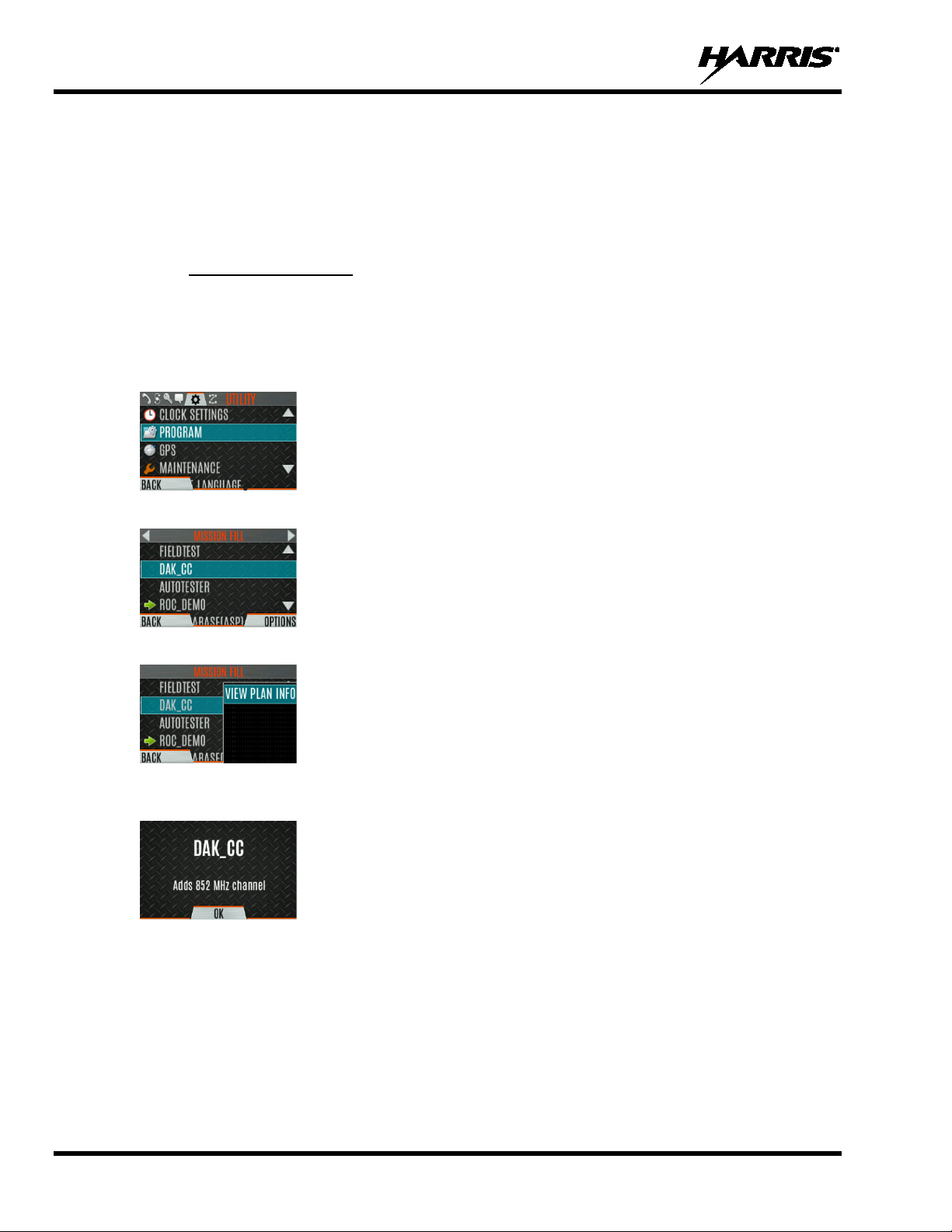
3. Press the up or down navigation buttons to highlight PROGRAM and press the Menu/Select button.
An arrow indicates the currently active personality.
4. Press the OPTIONS soft key.
5. Select VIEW PLAN INFO to view.
6. The radio displays the plan’s filename. Personality information appears if the field was filled out
using RPM2.
68
Page 2
14221-1800-2000, Rev. G
6.1.2 Change Active Personality
To change the active personality:
1. At main display, press the Menu/Selec t bu tton to access the main menu.
2. Press the left or right navigation buttons to display the UTILITY menu.
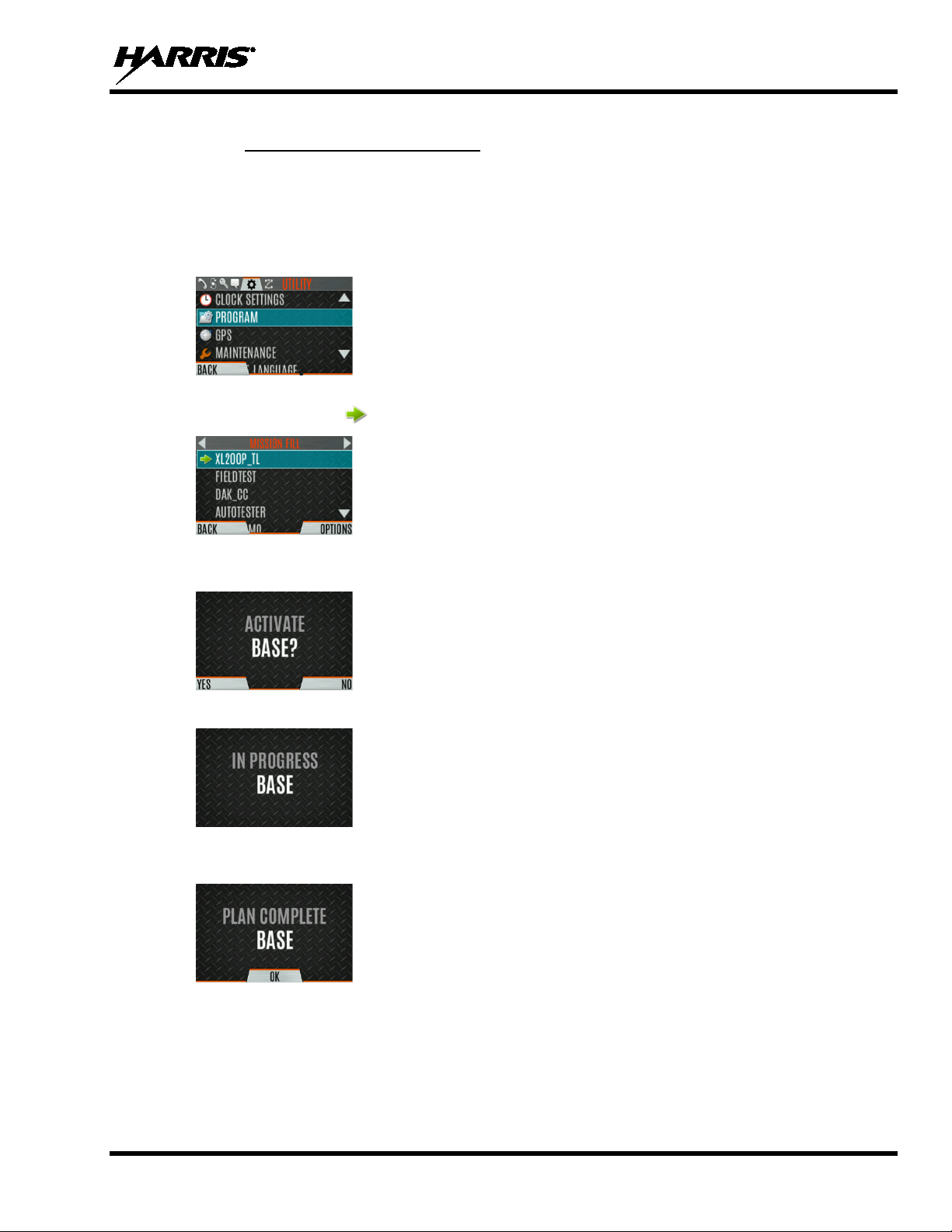
3. Press the up or down navigation buttons to highlight PROGRAM and press the Menu/Select button.
4. Press the up or down navigation buttons to highlight the desired personality and press the
Menu/Select button. indicates the currently active personality.
5. Press the YES soft key to confirm personality activation. If the personality has a power-up PIN, you
are prompted to enter the PIN before activation continues.
6. The IN PROGRESS screen is displayed while plan activation is in progress.
7. If personality is activated, the radio displays PLAN COMPLETE followed by the name of the
personality. Press the OK soft key.
• You cannot activate a personality when the radio is transmitting an emergency.
• A FAILED message may be displayed for errors such as invalid syntax in the fill or some other
invalid parameter.
69
Page 3
14221-1800-2000, Rev. G
6.2 SITUATIONAL AWARENESS (SA) – P 2 5 CO NV E NTIONAL ONLY
Situational Awareness is a feature in which the radio receives SA position from other units configured to
send the SA packets. The SA display shows the positions of the other radios (units) relative to the radio.
To make use of SA, all radios need to have a uniquely programmed Unit ID.
To display Situational Awareness Info:
1. Press the Menu/Select button to access the main menu.
2. Press the left or right navigation buttons to display the UTILITY menu.
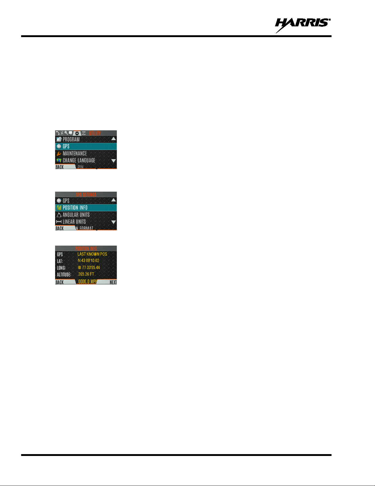
3. Press the up or down navigation buttons to select GPS and press the Menu/Select button.
4. Press the up or down navigation buttons to select POSITION INFO and press the Menu/Select
button.
5. Press the NEXT soft key.
6. Press the left or right navigation buttons to view the location of each unit. The color of each unit
indicates its status as follows. Only one status can be shown at a time and are listed in priority order:
• Grey – Unselected, no status
• Red – Unselected, In Emergency
• Orange – Unselected, Low Battery
• Blue - Unselected, Scanning
• Green – Selected, no status
• Green/Red – Selected, In Emergency
• Green/Orange – Selected, Low Battery
• Green/Blue – Selected, Scanning
7. GPS of this radio is shown by the center dot as follows:
• Green – Tracking
• Orange – Last known position
• Red – Searching
70
8. Press the up or down navigation buttons to zoom the display distance of current unit.
Page 4
14221-1800-2000, Rev. G
NOTE
9. Press the OPTIONS soft key. From here, select UNIT INFO to display details about the selected
unit, select REFRESH to update information, or select EXIT.
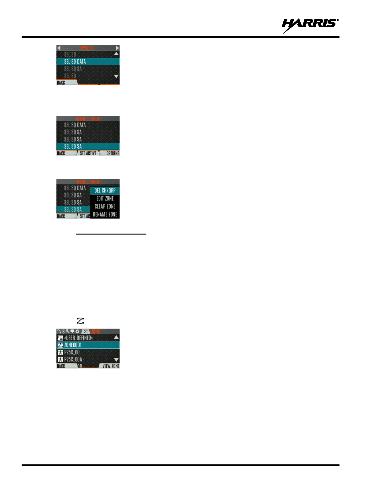
6.3 USER-DEFINED ZONES/SYSTEMS
6.3.1 Command Tactical Zone
A Command Tactical Zone is defined at the radio.
A Command Tactical Zone is reset when a Personality is activated.
To create a Command Tactical Zone:
1. Press the Menu/Select button to access the main menu.
2. Press the left or right navigation buttons to display the ZONE menu.
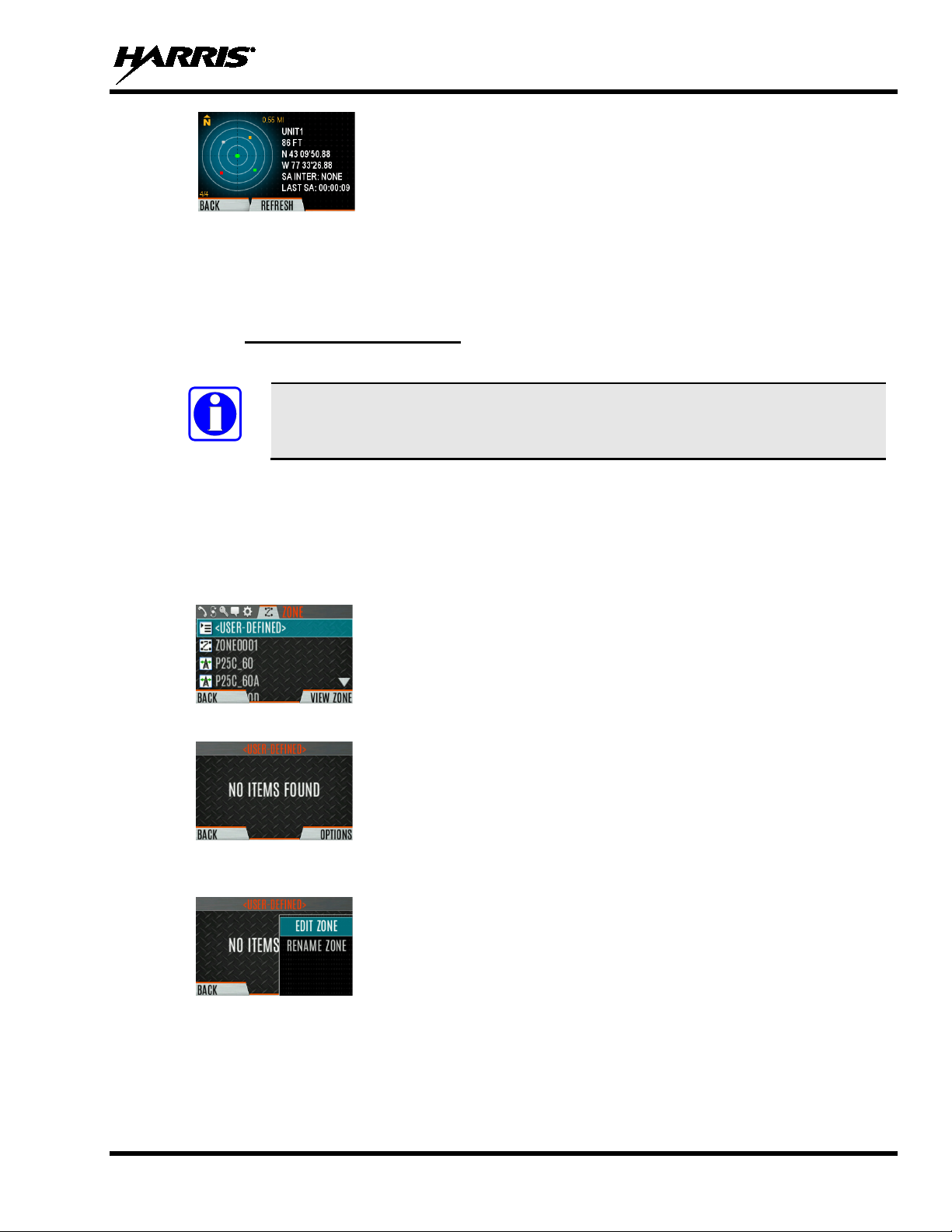
3. Press the up or down navigation buttons to highlight <USER-DEFINED> and press the VIEW
ZONE soft key.
4. Press the OPTIONS soft key.
5. Press the up or down navigation buttons to select EDIT ZONE to create a zone, or RENAME
ZONE to rename the Command Tactical Zone (up to 16 characters are allowed).
6. Press the left or right navigation buttons to scroll through existing systems. Press the up or down
navigation buttons to highlight desired channel/g roup.
7. Press the Menu/Select button to add or remove channel/group.
8. After adding all desired channels/groups, press the BACK soft key.
71
Page 5
14221-1800-2000, Rev. G
9. Activate the Command Tactical Zone by selecting the SET ACTIVE soft key on the USER
DEFINED screen, or by pressing the Menu/Select button when <USER DEFINED> is highlighted
on the Zone menu.
10. Aft er a creating a Command Tactical Zone, select OPTIONS to edit the Command Tactical Zone,
delete channels/groups, clear the zone, and rename the zone.
6.3.2 Mixed System Zone
Mixed System Zones are defined using RPM2 and cannot be edited on the radio. If a Mixed System Zone
is not configured using RPM2, it will not appear on the radio. Up to 50 Mixed System Zones can be
defined. You can view details about each channel/group. A user programmable button can be defined to
scroll through just the mixed system zones.
To view Mixed System Zones:
1. Press the Menu/Select button to access the main menu.
2. Press the left or right navigation buttons to display the ZONE menu.
3. Press the up or down navigation buttons to highlight the desired zone (Note: Zones are indicated
by the icon) and select VIEW ZONE to view the groups/channels in the zone list.
72
Page 6

14221-1800-2000, Rev. G
6.4 CH INFO MENU
The Channel Information (CH INFO) menu displays information about the currently selected channel.
The information displayed varies between conventional and trunked systems.
To display channel information:
1. Press while on the idle display.
2. Press the up or down navigation buttons to scroll through the programmed channel settings.
CONVENTIONAL OR P25 CHANNELS ONLY:
3. Press the EDIT soft key.
4. Enter the password. You may now select and change the values of the displayed channel parameters.
The password remains active until power cycle. Refer to Section 7.2 for more information.
6.5 AUDIO SETTINGS
From this menu, you can set audio settings such as speaker mute, noise cancellation, PTT, and tones.
1. Press the Menu/Select button to access the main menu.
2. Press the left or right navigation buttons to display the UTILITY menu.
3. Press the up or down navigation buttons highlight AUDIO SETTINGS and press the Menu/Select
button.
4. Press the up or down navigation buttons to scroll through available audio settings. Press the
Select/Menu button to change settings as desired:
• SPEAKER - Mute or Unmute the speaker audio.
• NOISE CANCELLATION - Enable or disable noise cancellation. Noise cancellation reduces
background noise during transmit.
• PTT - Enabl e or disable Push-To-Talk (PTT). Disable PTT to prevent accidental keying, such as
when the radio is in a holster or you are getting into a car.
• TONES - Enable or disable alert tones (see Table 5-6).
73
Page 7
14221-1800-2000, Rev. G
• KEYPAD TONES - Enable or disable keypad tones. When enabled, the radio plays a tone when
a button on the keypad is pressed.
5. Press the BACK soft key to exit menu.
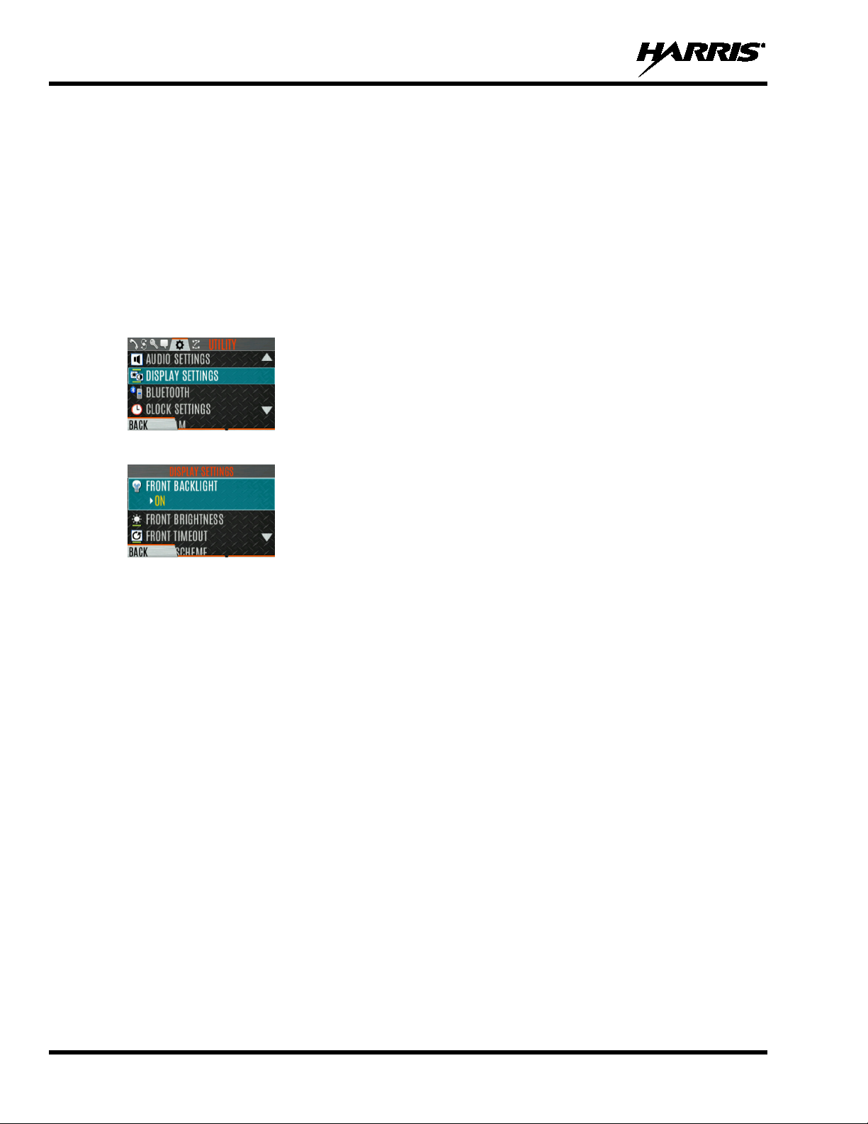
6.6 DISPLAY SETTINGS
To change display settings:
1. Press the Menu/Select button to access the main menu.
2. Press the left or right navigation buttons to display the UTILITY Menu.
3. Press the up or down navigation buttons to highlight DISPLAY SETTINGS and press the
Menu/Select button.
4. Press the up or down navigation buttons and the Select/Menu button to change settings as desired:
• COLOR SCHEME - Change the color scheme of the top and front dis plays for op ti mum vie win g
in day/night conditions.
• FRONT BACKLIGHT - Turn front display backlight on, off, momentary, or momentary (off).
Momentary (off) is similar to momentary, but the backlight turns off completely and only comes
on when the center navigation button is pressed.
• FRONT BRIGHTNESS - Set brightness level of front display. A level of 0 has same effect as
turning off backlight.
• FRONT TIMEOUT - Specify how long the radio needs to be inactive before the front display’s
backlight turns off.
• TOP BACKLIGHT - Specify how long the top display’s backlight will remain lit:
MOMENTARY, ON, or OFF.
• TOP BRIGHTNESS - Set the brightness level of the top display. A level of 0 turns off top display
and indicator (TX/RX) LED.
• TOP TIMEOUT - Specify how long the radio needs to be inactive before the top display’s
backlight turns off.
• TOP ORIENTATION - Set orientation of top display to be viewed from radio: FRONT, BACK,
or AUTO.
When AUTO is selected, the radio changes the top display to be viewed from back if an external
microphone or speaker is attached. Otherwise, the display can be viewed from the front.
74
• INDICATOR LED - Toggle the indicator LED ON/OFF.
Page 8

14221-1800-2000, Rev. G
5. Press the BACK soft key to exit the menu.
75
Page 9
14221-1800-2000, Rev. G
NOTE
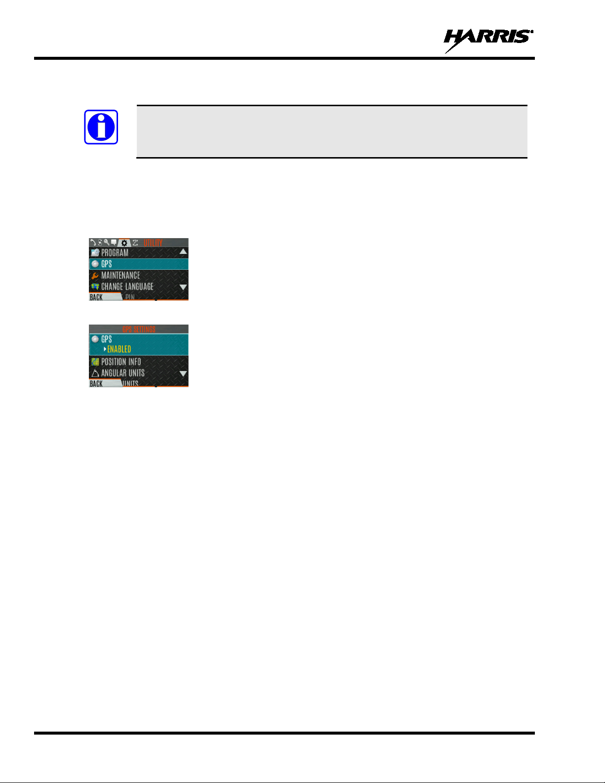
6.7 GPS SETTINGS
The GP S SETTINGS menu it em only appears if enabled using RPM2 and the feature
is installed.
To access GPS settings:
1. Press the Menu/Select button to access the main menu.
2. Press the left or right navigation buttons to display the UTILITY menu.
3. Press the up or down navigation buttons to highlight GPS and press the Menu/Select button.
4. Use the up or down navigation buttons and the Select/Menu button to change settings as desired:
• GPS - Enable or disable internal GPS.
• POSITION INFO - See Section 6.8.
• LINEAR UNITS - Set unit of measurement of displayed linear units: STATUTE, METRIC, or
NAUTICAL.
• ANGULAR UNITS - Set unit of measurement of displayed angular units: CARDINAL,
DEGREES, or MILS.
• POSITION FORMAT- Set format of displayed position information: Latitude/Longitude
Decimal Degrees (LAT LONG DD), Latitude/Longitude Degrees Minutes Seconds (LAT/LONG
DMS), LAT/LONG DM, Military Grid Reference System (MGRS), or Universal Transverse
Mercator (UTM).
5. Press the BACK soft key to exit the menu.
6.8 POSITION INFO
The Position Info screen displays the radio user’s location information. GPS must be enabled in the GPS
Settings (see Section 6.7).
To display position info:
1. Press the Menu/Select button to access the main menu.
2. Press the left or right navigation buttons to display the UTILITY menu.
3. Press the up or down navigation buttons to highlight POSITION INFO and press the Menu/Select
button.
76
Page 10
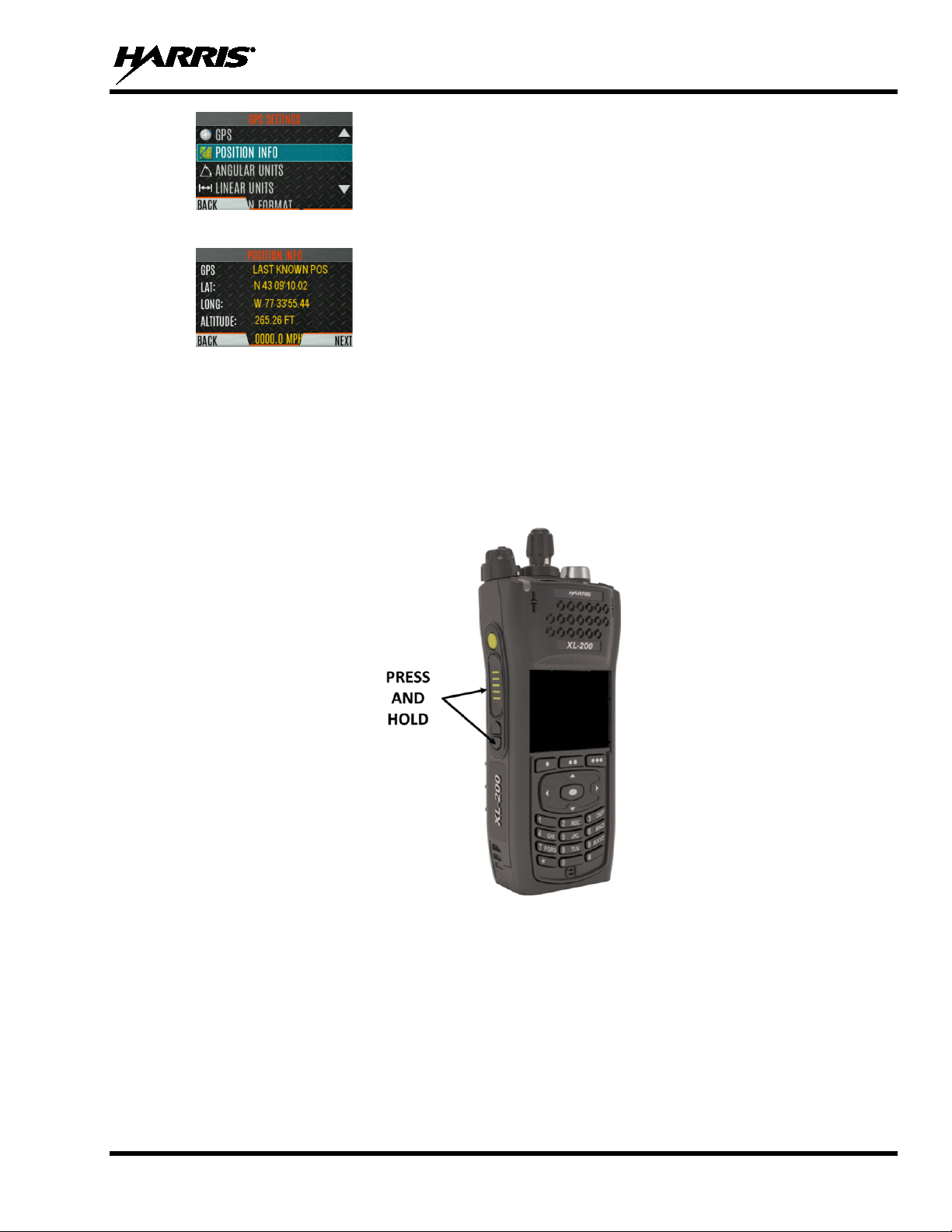
4. Press the up or down navigation buttons to scroll throu g h available location inform ation.
6.9 WI-FI
The XL-Portable supports programming via Wi-Fi. Refer to Appendix A for information on configuring
Wi-Fi.
To enable Wi-Fi programming mode on the radio:
1. Ensure the radio is powered off.
2. Press and hold the bottom side button and PTT button (see Figure 4-1).
14221-1800-2000, Rev. G
Figure 6-1: Enabling Wi-Fi
3. Power on the radio.
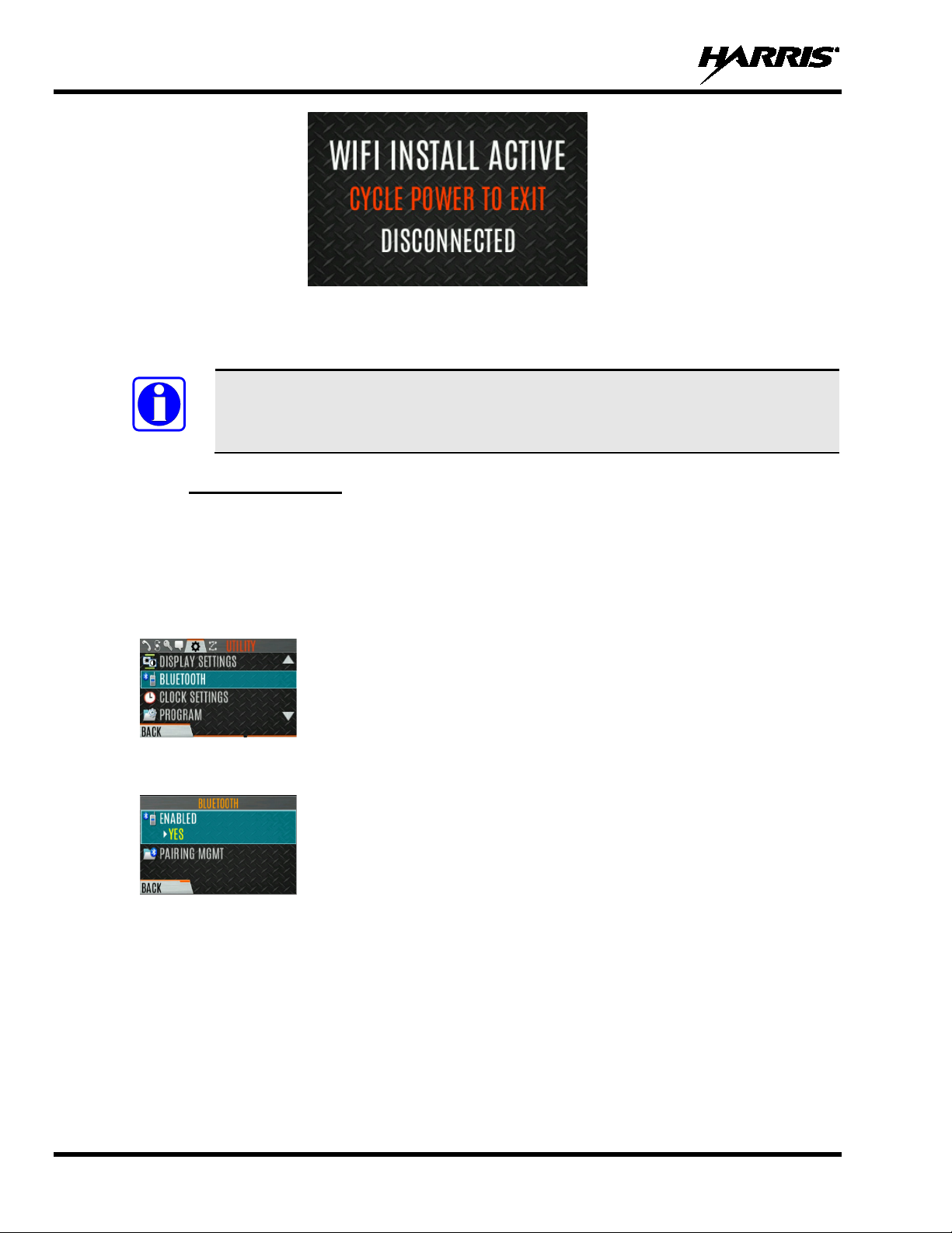
4. The WIFI INSTALL ACTIVE screen is displayed (Figure 6-2). The radio displays
DISCONNECTED if not connected to a wireless network, or CONNECTED if connected to a
wireless network.
77
Page 11
14221-1800-2000, Rev. G
NOTE
Figure 6-2: Wi-Fi Install Active
6.10 BLUETOOTH
The BLUETOOTH menu item only appears if enabled using RPM2 and if the feature is
installed.
6.10.1 Enable Bluetooth
To enable Bluetooth:
1. Press the Menu/Select button to access the main menu.
2. Press the left or right navigation buttons to display the UTILITY menu.
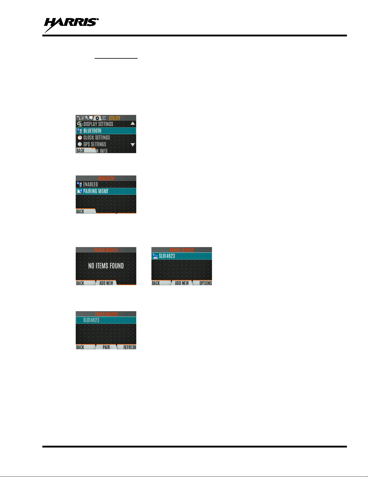
3. Press the up or down navigation buttons to highlight BLUETOOTH and press the Menu/Select
button.
4. Press the up or down navigation buttons to high li ght ENABLED and press the Menu/Select button to
toggle YES/NO.
78
Page 12
14221-1800-2000, Rev. G
6.10.2 Pair Devices
To pair devices:
1. Press the Menu/Select button to access the main menu.
2. Press the left or right navigation buttons to display the UTILITY menu.
3. Press the up or down navigation buttons to highlight BLUETOOTH and press the Menu/Select
button.
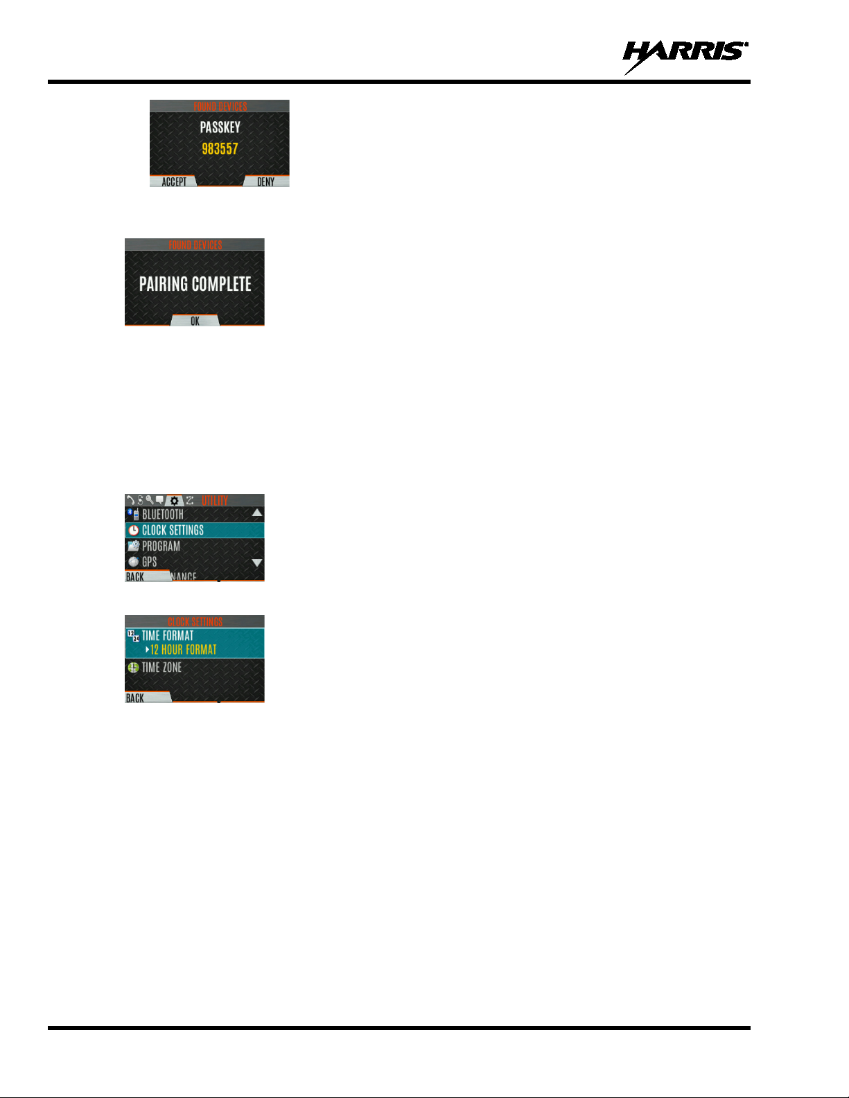
4. Press the up or down navigation buttons to highlight PAIRING MGMT and press the Menu/Select
button.
5. Make sure device being paired is powered on and has discovery mode enabled to pair w ith the radio.
If no devices are found and Bluetooth is enabled, only the ADD NEW soft key is available. If devices
are paired, the OPTIONS soft key appears.
6. Press the ADD NEW soft key to select a device to pair.
7. A list of available Bluetooth devices appears.
8. Press the REFRESH soft key to refresh the device list if the desired device does no t appea r.
9. Press the up or down navigation buttons highlight the d esired device and press the PAIR softkey.
10. Pairing progress is displayed.
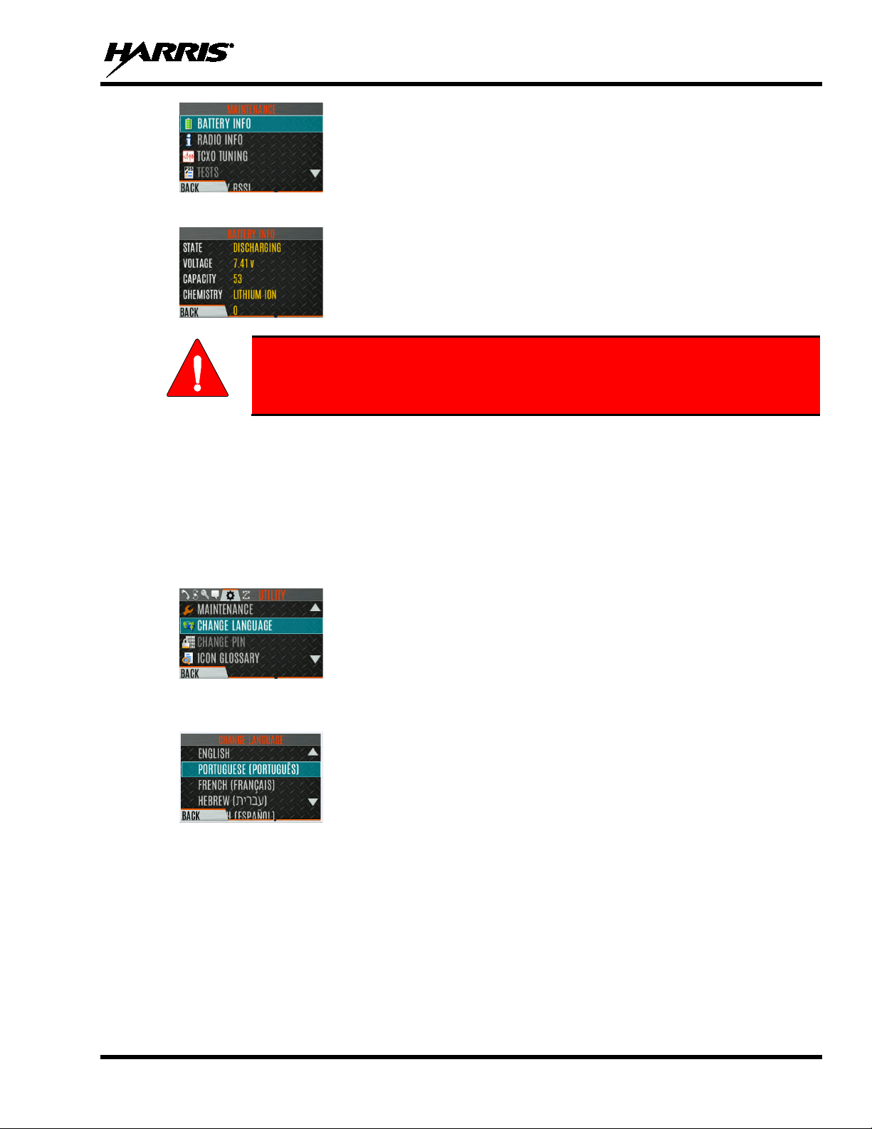
• For Bluetooth 2.0 devices, a pin code screen appears.
Enter the pin code and select OK.
• For Bluetooth 2.1 devices, a PASSKEY accept/deny screen appears. Select ACCEPT.
Accept the passkey on the Bluetooth 2.1 device as well.
79
Page 13
14221-1800-2000, Rev. G
11. A PAIRING COMPLETE message appears when pairing is complete. Select OK. The paired
device is then displayed in the PAIRED DEVICES list.
6.11 CLOCK SETTINGS
To view/change clock settings:
1. Press the Menu/Select button to access the main menu.
2. Press the left or right navigation buttons to display the UTILITY menu.
3. Press the up or down navigation buttons to highlight CLOCK SETTINGS and press the Menu/Select
button.
4. Use the up or down navigation buttons and Menu/Select button to change settings as desired:
• TIME FORMAT- Set 12 or 24-hour time display format.
• TIME ZONE - Set time zone relative to Universal Time Coordinated (UTC).
5. Press the BACK soft key to exit.
6.12 BATTERY INFO
To display battery information:
1. Press the Menu/Select button to access the main menu.
2. Press the left or right navigation buttons to display the UTILITY menu.
3. Press the up or down navigation buttons to highlight MAINTENANCE and press the Menu/Select
button.
4. Press the up or down navigation buttons to highlight BATTERY INFO and press the Menu/Select
button.
80
Page 14
14221-1800-2000, Rev. G
Use only Harris approved batteries. Injury could occur from using incorrect
WARNING
5. Battery information is displayed (state, voltage, capacity, and chemistry).
battery.
6.13 SELECT LANGUAGE
To change the language displayed by the radio:
1. Press the Menu/Select button to access the main menu.
2. Press the left or right navigation buttons to display the UTILITY menu.
3. Press the up or down navigation buttons to highlight CHANGE LANGUAGE and press the
Menu/Select button.
4. Press the up or down navigation buttons to hi ghlight the desired language and press the Menu/Select
button.
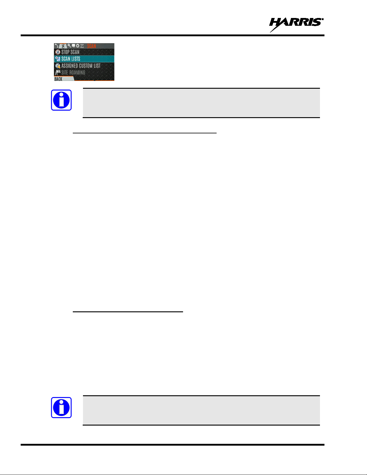
6.14 SET UP SCAN
These procedures are used to set up the scan list, home channels, and priority channels.
To access the scan lists:
1. Press the Menu/Select button to access the main menu.
2. Press the left or right navigation buttons to display the SCAN menu.
3. Press the up or down navigation buttons to highlight SCAN LISTS and press the Menu/Select button.
Refer to the following sections.
81
Page 15
14221-1800-2000, Rev. G
NOTE
NOTE
When using Preemptive Priority Scan, the frequencies in the list need to be unique.
6.14.1 Default, Priority 1, and Priority 2 Channels
6.14.1.1 Default Channel
This is the currently selected channel and is the channel you transmit on by default when you press PTT
while the radio is actively scanning and is not responding to a just received call. Responding to a call the
radio just received while scanning is called hang time. If hang time is set to 0 using RPM2, the r adio
always transmits on the default channel in scan.
6.14.1.2 Priority 1 Channel
This channel will be scanned more often than other channels in the list and will be scanned in between
every other channel in the scan list. An example scan sequence would be P1 (priority 1), C2, P1, C3, P1,
C4, etc. In addition, the priority channel will be scanned even while actively receiving on a non-priority
channel. For example, if the radio is actively receiving on C3 and activity is detected on P1, the radio will
drop C3 and switch to P1.
6.14.1.3 Priority 2 Channel
This channel will also be scanned more often than others. An example scan sequence would be P1, C2,
P1, C3, P1, C4, P2, C5, P1, C6, P1, C7, P1, C8, P2, C9 etc. In addition, this channel will be scanned even
while actively receiving on a non-priority channel. For example, if t he radio is actively r eceiving o n C3
and activity is detected on P2, the radio will drop C3 and switch to P2. Additionally, activity on P1 can
also preempt P2, but P2 cannot preempt P1.
6.14.2 Trunked/Conventional Scanning
Trunked/conventional scanning adds the ability to scan multiple conventional and P25 conventional
channels while still maintaining trunked radio operation. The radio can scan a conventional scan list while
still receiving a trunked control channel and receiving trunked calls. Selection of which conventional
scan list is associated with a given trunked system is done using RPM2 a nd cannot be changed on the
radio. However, a user with access to the necessary menu layout (see Section 5.8) can edit the scan list
members (both trunked groups and conventional channels on the selected Conventional Priority
System). As the number of conventional channels being scanned increases, the time between scanning
each channel increases (roughly 250 milliseconds per channel), with the consequent increase in the
number of calls that will late-enter. To avoid missing calls, it is recommended to keep the number of
conventional channels being scanned to eight (8) or fewer.
The trunking site must have roaming set to Enhanced CC.
82
Page 16

14221-1800-2000, Rev. G
NOTE
6.14.3 Vote Scan (Analog and P25 Conventional Only)
If vote scan is enabled via RPM2, the radio automatically selects the strongest signal ensuring that the
best audio quality is delivered to the user. If vote scan is enabled, the radio is always scanning. You
cannot stop scanning, start normal scanning, or monitor the channel. The scanning icon on the idle screen
indicates that the radio is vote scanning versus, regular scanning.
If Talkaround is enabled, Vote Scan is dis ab le d un t il Talk around is disabled again.
6.14.4 Edit Scan List
Depending on the scan list options selected via RPM2, you may be able to add or remove channels/groups
from the scan list.
To edit the scan list:
1. Press the Menu/Select button.
2. Press the left or right navigation buttons to display the SCAN menu.
3. Press the up or down navigation buttons to select SCAN LISTS.
4. Press the up or down navigation buttons to highlight the scan list and press the Menu/Select button.
5. Press the up or down navigation buttons to highlight channel/group.
6. Select OPTIONS.
7. Press the up or down navigation buttons to select ADD CHAN/DELETE CHAN, SET PRI1, SET
PRI2, REMOVE PRI, or NUISANCE/ADD BACK.
83
Page 17
14221-1800-2000, Rev. G
When a channel is not grayed out in the list, DELETE CHAN appears. When a channel/group is
grayed out (not in list), ADD CHAN appears.
8. Press the Menu/Select button to toggle selection.
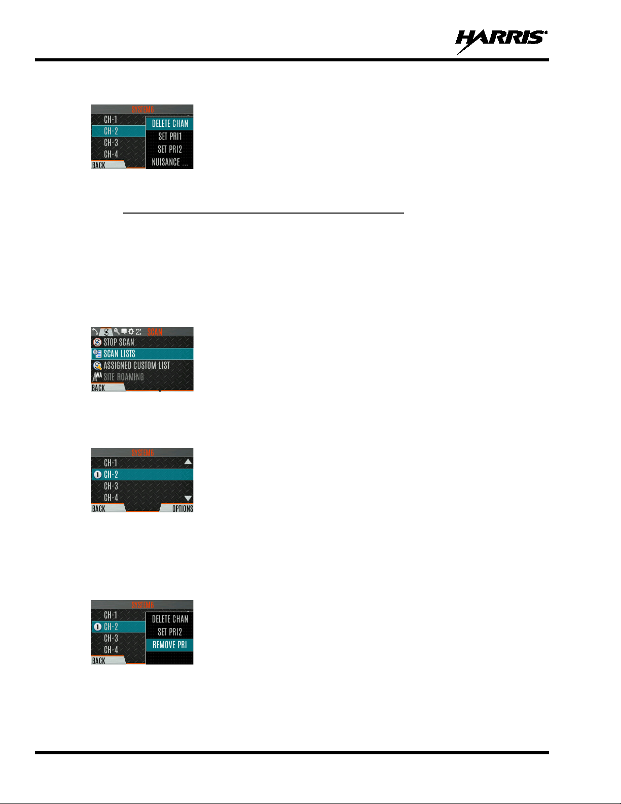
6.14.5 Set or Remove Priority 1 and Priority 2 Channels
Priority channels are scanned more often than non-priority channels. Note that P1 and P2 can only be set
if configured as “Keypad” and the scan list is not set to “Fixed” using RPM2.
To set or remove priority 1 and priority 2 channels:
1. Press the Menu/Select button.
2. Press the left or right navigation buttons to display the SCAN menu.
3. Press the up or down navigation buttons to highlight SCAN LISTS and press the Menu/Select button.
4. Press the up or down navigation buttons to highlight the desired scan list and press the Menu/Select
button.
5. Press the up or down navigation buttons to highlight the desired channel/group.
6. Select OPTIONS.
7. Press the up or down navigation buttons to highlight SET PRI1 or SET PRI2 and press the
Menu/Select button. A Priority 1 channel appears with a P1 and a Priority 2 channel appears with a
P2.
8. Select REMOVE PRI to remove priority.
84
Page 18

14221-1800-2000, Rev. G
6.14.6 Custom Scan Lists
The Mixed Zone Scan (MZS) feature gives the user the capability to scan based on a custom scan list that
is assigned at the system level. The Custom Scan (CS) list can contain System and Channel/Group
configurations across P25 Trunked, P25 Conventional, and Analog Systems. When a Custom Scan List is
assigned to a P25T system, the radio can scan P25T, P25C and Analog systems. When assigned to a
P25C or Analog system, the radio only scans conventional channels. MZS also gives the user the
capability to scan beyond the selected system group set.
• P25T Scan
When a custom scan list is assigned to a P25T system, the user can scan P25T, P25C, and Analog
groups/channels. All P25T systems must have the same WACN, System ID, and Unit ID to be added
to the custom scan list. If P25C and/or analog channels are added to the custom scan list, the radio
will scan them using the Trunked/Conventional scan feature described in section 6.14.2, and will
override any other conventional scan list that may have been programmed using RPM2.
• P25C and Analog Scan
When a custom scan lists is assigned to a P25C or Analog System, the user can scan P25C and
Analog channels. P25T systems are ignored.
Custom scan list can be created using RPM or at the radio. The radio supports up to 10 Custom Scan lists,
with up to 100 channels/groups in each.
85
Page 19

14221-1800-2000, Rev. G
6.14.6.1 Create Custom Scan List
To create a custom scan list at the radio:
1. Press the Menu/Select button.
2. Press the left or right navigation buttons to display the SCAN menu.
3. Press the up or down navigation buttons to highlight ASSIGNED CUSTOM LIST and press the
Menu/Select button.
4. Press the OPTIONS softkey.
5. Select ADD SCAN LIST.
6. Press the up or down navigation buttons to highlight the newly added scan list and press the
VIEW/EDIT soft key.
7. Press the left or right navigation buttons to display the desired sy stem .
8. Press the up or down navigation buttons to highlight the desired group/channel and press the
OPTIONS softkey. From here, you can add/delete channels from the scan list, and set/remove
Priority 1 and Priority 2 channels.
86
Page 20

14221-1800-2000, Rev. G
NOTE
NOTE
When a custom scan list is selected, that list is scanned any time scanning is enabled
for any Trunked, conventional, or P25 Conventional system. To scan only the channels
assigned to a system, custom scanning must be turned off.
6.14.7 Wide Area System Scan (P25 Trunked and EDA CS)
Wide Area System Scan (WASCAN) causes the radio to roam across mobile systems when the currently
selected system's control channel is lost. The radio will scan the control channels of other systems.
To enable/disable Wide Area System Scan:
1. Press the Menu/Select button to access the main menu.
2. Press the left or right navigation buttons to display the SCAN menu.
3. Press the up or down navigation buttons to highlight SITE ROAMING and press the Menu/Select
button to toggle Wide Area System Scan ENABLED/DISABLED.
4. Select BACK to exit the scan menu.
6.14.8 Site Lock
The Site Lo c k fe at u re allows the user to select a site from a Site Alias list to lock to; i.e., prevent the radio
from roaming. Up to 512 sites can be programmed to the radio.
1. Press the Menu/Select button to access the main menu.
2. Press the left or right navigation buttons to display the SCAN menu.
3. Press the up or down navigation buttons to highlight SITE ALIAS and pr ess the Menu/Select button
to display the list of available sites.
4. Press the up or down navigation buttons to highlight the desired site alias and press the Menu/Select
button to lock to this site.
6.15 RADIO STATUS
The status feature allows the radio user to send a status condition to the site without making a voice call.
There can be up to 10 status conditions programmed into the radio. For each status defined, there is an ID
and an alphanumeric name. The ID is sent to the site and the alphanumeric name appears on the radio
display when the ID corresponds with the information programmed at the site.
A button on the radio can be programmed to send a radio status (see Section 7.4).
To send a radio status:
1. Press the Menu/Select button to access the main menu.
2. Press the left or right navigation buttons to display the MESSAGES menu.
87
Page 21

14221-1800-2000, Rev. G
NOTE
3. Press the up or down navigation buttons t o highlight RADIO STAT US and press the Menu/Select
button.
4. Use the up or down navigation buttons and the Menu/Select button to highlight and select desired
status.
6.16 RADIO MESSAGE
The message feature is used to send a message to the site without making a voice call. There can be up to
10 messages programmed i nto the radio. For each message defined, there is an ID and an alphanumeric
name. The ID is sent to the site and the alphanumeric name appears on the radio display when the ID
corresponds with the information programmed at the site.
A button on the radio can be programmed to send a radio message (see Section 7.4).
To send a radio message:
1. Press the Menu/Select button to access the main menu.
2. Press the left or right navigation buttons to display the MESSAGES menu.
3. Press the up or down navigation buttons to highlight RADIO MESSAGE and press the Menu/Select
button.
4. Use the up or down navigation buttons and the Menu/Select button to highlight and select the desired
message.
88
Page 22

14221-1800-2000, Rev. G
6.17 RADIO TEXTLINK
Radio TextLink provides short text messaging functionality for radios. Due to the difficulty of entering
text messages on a radio, predefined "canned" messages and predefined replies can be stored in the radio.
To facilitate sending messages where informat ion must be provided at send time, text message forms can
also be stored in the radio. A form can contain up to four (4) text prompts, for which the operator enters
alphanumeric values before sending the message.
89
Page 23

14221-1800-2000, Rev. G
6.17.1 Radio TextLink Messages
To send a canned Radio TextLink messag e:
1. Press the Menu/Select button to access the main menu.
2. Press the left or right navigation buttons to display the MESSAGES menu.
3. Press the up or down navigation buttons to highlight TEXTLINK MESSAGES and press the
Menu/Select button.
4. Press the left or right navigation buttons to display the desired message.
• Press the Menu/Select button to send the messag e.
• Select CHG CALLEE to change the destination for the message.
• Select TOD QUERY to get the time of day.
6.17.2 Radio TextLink Forms
Form messages are displayed and stored in the radio as a message in which each field to be filled is
indicated by a question mark (?) followed by one or more asterisks (*). The number of asterisks indicates
the maximum number of alphanumeric characters allowed for that field.
To send a Radio TextLink form:
1. Press the Menu/Select button to access the main menu.
2. Press the left or right navigation buttons to display the MESSAGES menu.
3. Press the up or down navigation buttons to highlight TEXTLINK FORMS and press the
Menu/Select button.
4. Press the left or right navigation buttons to displ ay the desired message and press the Menu/Select
button.
5. Enter text into blank field(s) (up to eight alphanumeric characters) and press the NEXT soft key.
90
Page 24

14221-1800-2000, Rev. G
6. Select SEND t o send the message. Select CHG CALLEE to change the destination for the message.
Select TOD QUERY to get the time of day.
6.17.3 View Received Messages
When the icon appears on the idle display , there are Radio TextLink messages waiting to be read.
To view received Radio TextLink messages:
1. Press the Menu/Select button to access the main menu.
2. Press the left or right navigation buttons to display the MESSAGES menu.
3. Press the up or down navigation buttons to highlight TEXTLINK MAILBOX and press the
Menu/Select button. From the mailbox, select OPTIONS to delete messages, view details of
messages, and reply to messages.
6.18 FAULTS/ALERTS
is displayed on the idle display when there is a fault.
To view and clear faults/alerts:
1. Press the Menu/Select button to access the main menu.
2. Press the left or right navigation buttons to display the MESSAGES menu.
3. Press the up or down navigation buttons to highlight FAULTS/ALERTS and press the Menu/Select
button.
4. Fault messages are displayed. Press the up or down navigation buttons to highlight the desired fault.
Press the OPTIONS soft key delete faults. Press the DETAILS soft key to view details for the
highlighted fault.
91
Page 25

14221-1800-2000, Rev. G
Possible faults include:
• BATTERY FAULT- Replace battery.
• EEPROM FAULT - Contact Harris.
• RF FAULT - Contact Harris.
• OVERCURRENT - Check antenna and antenna connection. Try replacing antenna.
• INVALID SYSTEM - Feature not installed.
• CHANNEL FAULT - Channel frequency programmed is not valid for this radio.
5. If you view but do not delete the fault, the alert icon goes away on the idle display.
Contact Harris for assistance with diagnosing a fault.
6.19 TONE ENCODE
Tone Encode is a generic tone encoding scheme for call identification when transmitting on a
conventional system. It supports generic user-definable tone encode (up to 15 tones), Type 99 (up to 2
tones) and 5/1 Tone (up to 5 tones) encoding formats.
Tone encoding schemes are used to transmit calls to one or more target radios that have been programmed
with the correct tone decode sequence. When the receiving radio detects its tone decode sequence, it
unmutes on the call.
To select a Tone Encode option:
1. Press the Menu/Select button to access the main menu.
2. Press the left or right navigation buttons to display the CALL menu.
3. Press the up or down navigation buttons to highlight TONE ENCODE and press the Menu/Select
button.
4. Select the desired Tone Encode option from the list.
92
Page 26

14221-1800-2000, Rev. G
6.20 ENCRYPTION
6.20.1 Create and Load Keys
Refer to the following documentation for advanced programming and setup instructions:
• Harris OTAR Overview Manual - MM-008069-001
• Network Key Manager Installation and Configuration Manual - MM-008070-001
• Harris UAS Key Management Application Manual - MM-008068-001
• Harris Key Manager Key Admin Overview and Operation Manual - MM1000019423
• Harris Key Manager Key Loader Overview and Operation Manual - MM1000019424
®
• Motorola
• Motorola KVL 4000 Key Variable Loader (KVL) User's Guide
6.20.2 Zeroize Keys from Radio
It may be necessary to remove keys because of compromise or expiration.
To zeroize keys from the radio:
KVL 3000 Plus Key Variable Loader (KVL) User's Guide
1. Press the Menu/Select button to access the main menu.
2. Press the left or right navigation buttons to display the SECURITY menu.
3. Press the up or down navigation buttons highlight ZEROIZE KEYS and press the Menu/Select
button.
4. Press the YES softkey to remove the keys. This will also remove the keysets.
6.20.3 Protected Keys
The Prot ected Keys feature transfers P25 Voice Keys, from Harris Key Loader to the radio, that have
been wrapped (AES) or encrypted (DES) with Key Protection Keys (KPKs). KPKs are nothing more than
unprotected Key Encryption Keys (KEKs). The KPKs need to be loaded into the radio before the
Protected Keys are loaded. Once loaded into the radio, the KPKs are used to unwrap (AES ) or decrypt
(DES) the Protected Keys.
93
Page 27

14221-1800-2000, Rev. G
6.20.4 Global Encryption
Global Encryption can be enabled when encryption keys are loaded on the radio and the selected
Zone/System is encrypted. When Glo bal Enc rypt ion is enabled on the radio, a Global Key is used for all
encrypted transmissions until:
• Global Encryption is disabled.
• A new personality is activated.
• The active keyset is changed.
• The system is changed.
Global Encryption behavior is available on all channels that support encrypted communications.
To enable Global Encryption and/or change Global Encryption Key:
1. Press the Menu/Select button to access the main menu.
2. Press the left or right navigation buttons to display the SECURITY menu.
3. Press the up or down navigation buttons to highlight GLOBAL ENCRYPTION. Press the
Menu/Select button.
4. Press the up or down navigation buttons to highlight the desired Global Key and press the
Menu/Select button to enable Global Encryption.
5. To change the selected global key, press the up or down navigation b uttons to highlight GLOBAL
KEY on the SECURITY menu. Press the Menu/Select key.
6. Press the up or down navigation buttons to highlight the global key and press the Menu/Se lect button.
7. RPM2 allows Key Numbers to be given Key Names.
94
8. The optional global key icon is displayed on the main display.
Page 28

14221-1800-2000, Rev. G
6.20.5 Select Keyset
To select a keyset:
1. Press the Menu/Select button to access the main menu.
2. Press the left or right navigation buttons to display the SECURITY menu.
3. Press the up or down navigation buttons to select ACTIVE KEYSET. Press the Menu/Select button
to toggle to the inactive keyset.
6.20.6 View Key List
To view the key list:
1. Press the Menu/Select button to access the main menu.
2. Press the left or right navigation buttons to display the SECURITY menu.
3. Press the up or down navigation buttons to select KEY LIST and press the Menu/Select button.
4. The available key lists are displayed.
6.20.7 Delete Individual Keys
To delete indiv idu al keys from a keyset:
1. Press the Menu/Select button to access the main menu.
2. Press the left or right navigation buttons to display the SECURITY menu.
3. Press the up or down navigation buttons to select KEY LIST and press the Menu/Select button.
4. The available key lists are displayed.
95
Page 29

14221-1800-2000, Rev. G
5. Select the desired keyset and press the Menu/Select button to display the individual keys. Highlight
the desired key and press the Delete softkey.
6.20.8 OTAR Configuration
OTAR is t he over-the-air-rekeying from a KMF and must be enabled for the digita l only chan nel using
RPM2. For OTAR operation, the appropriate KEKs must be loaded into the radio using the Harris Key
Loader or a KVL device.
The KMF Configuration must include the RSI of the KMF and the appropriate Message Number Period.
To enable OTAR and request rekey:
1. Press the Menu/Select button to access the main menu.
2. Press the left or right navigation buttons to display the SECURITY menu.
3. Press the up or down navigation buttons to highlight OTAR and press the Menu/Select button to
toggle ENABLED/DISABLED.
4. Press the up or down navigation buttons to select OTAR REKEY and press the Menu/Select button to
request that the KMF updates the keys in the radio. OTAR REKEY is only enabled if the radio has
successfully registered for data operations. If enabled via programming, the radio plays an audible
confirmation tone to indicate successful OTAR rekey.
6.21 SITE ALIAS AND SITE LOCK (P25 TRUNKED ONLY)
96
The Site Alias feature allows the user to view the site name of the current site that the radio is on. The
Site Lock feature provides a list of available, adjacent sites that the user can lock the radio to. The Site
Lock feature restricts the radio from roaming between sites.
Page 30

14221-1800-2000, Rev. G
Ensure that the radio is turned off before connecting the programmi ng cable. After the
CAUTION
NOTE
CAUTION
7. PROGRAMMING
This section provides information on front panel programming. Programmi ng can also be accomplished
by creating a plan using a computer with RPM2 installed.
7.1 PROGRAMMING VIA RPM2
Radio Personality Manager (RPM2) is used for the bulk of programming the radio. With RPM2, you can
fully program the XL-Portable using cable 12082-0410-A1.
Removing power during radio programming, or programming the radio with low battery
power could corrupt installation of firmware.
cable is connected, then power on the radio.
7.2 EDIT CHANNEL (ANALOG AND P25 CONVENTIONAL ONLY)
Channels can be edited from the Channel Information (CH INFO) menu display. Most of the displayed
channel parameters can be modified here. Channel edits persist across a power cycle. Loading a
personality clears any channel edits. Available parameters vary depending on whether the channel is a
P25 or analog channel.
To edit a channel:
1. From the main display, press to access the CH INFO screen.
2. Press the up or down navigation buttons to scroll through the programmed channel settings.
3. Press the EDIT soft key.
Only authorized users should attempt channel editing.
4. Enter the password programmed via RPM2. You do not have to re-enter the password until you
power cycle the radio.
5. Press the ENTER soft key.
97
Page 31

14221-1800-2000, Rev. G
is not available on this screen if it was enabled from the
NOTE
6. Highlight and select the parameter to edit. For P25 channels, modify remaining channel settings:
• CHANNEL NAME - T he Channel Name cannot be changed from this screen; RPM2 is required
to change the Channel Name.
• RX FREQUENCY - Receive frequency. Note that if the new frequency is invalid, the display
reverts to the old frequency (Table 7-1).
• TX FREQUENCY - Transmit frequency.
• TX POWER - Transmit power. Toggle between LOW and HIGH.
• TALKGROUP - Select a talkgroup for the channel. Talkgroup name cannot be set here.
• RX NAC - Network Access Code (NAC) radio uses for Normal squelch in receive.
• TX NAC - NAC radio transmits to break Normal squelch on receiving radio.
• P25 SQUELCH - Select type the radio uses in receive. Select NORMAL, SELECTIVE, or
MONITOR.
• RX CHAN GUARD – Squelch type radio uses in receive. Select Noise, CTCSS, or CDCSS. For
a digital channel, the RX CHAN GUARD is used to receive from a Conventional analog channel
that is on the same frequency and uses the selected Channel Guard.
RX CODE - Code radio looks to unmute the speaker on the receiving radio when CDCSS
squelch is used in conventional mode.
RX TONE - Tone radio looks to unmute the speaker on the receiving radio when CTCSS
squelch is used in conventional mode.
7. For analog channel, modify remaining channel settings:
• CHANNEL NAME - T he Channel Name cannot be changed from this screen; RPM2 is required
to change the Channel Name.
• TX FREQUENCY - Transmit frequency.
• TX POWER - Transmit power. Toggle between HIGH and LOW.
• RX CHAN GUARD - Squelch type radio uses in receive. Select Noise, CTCSS, or CDCSS.
RX TONE - Tone radio uses to break selective squelch on receiving radio. This is available
when RX squelch is set to CTCSS.
RX CODE - Code radio uses to break selective squelch on receiving radio. This is available
when RX squelch is set to CDCSS.
RX CHAN GUARD
CALL menu as per Section 5.22.
• TX CHAN GUARD - Squelch type radio uses in transmit. Select None, CTCSS, or CDCSS.
98
Page 32

14221-1800-2000, Rev. G
is not available on this screen if it was enabled from the
the asterisk goes away and the channel is no longer
NOTE
NOTE
TX TONE - Tone sent by transmitting radio to allow receiving radio to unmute when CTCSS
squelch is used in conventional mode.
TX CODE - Code sent by transmitting radio to allow receiving radio to unmute when CDCSS
squelch is used in conventional mode.
TX CHAN GUARD
CALL menu as per Section 5.22.
8. An asterisk is displayed in front of the CHANNEL label on the main display when a channel has been
edited. The asterisk is NOT shown for TX Power or Talkgroup changes.
When the only item edited is the TX or RX CHAN GUARD valu es, and then CHAN
GUARD edit is Disabled,
considered edited. This is the only editable item for which this is true.
Table 7-1: Valid Frequency Ranges
INTERNATIONAL
(NON-REBANDED)
136 - 174 MHz
378 - 522 MHz
763 - 776 MHz 768 - 776 MHz 6250 kHz
793 - 806 MHz
806 - 825 MHz
851 - 870 MHz
US
(REBANDED)
136 - 174 MHz 2500, 5000, or 6250 Hz
378-522 MHz 2500, 5000, or 6250 Hz
798 - 806 MHz 6250 kHz
806 -8 16 MHz 6250 kHz
851 - 861 MHz 6250 kHz
FREQUENCY RESOLUTION
7.3 OTAP
The radio supports Over-the-Air-Programming (OTAP) via ProFile Manager. RPM2 c reates, modifies
and stores personality information while ProFile Manager delivers the personality over the network to the
desired radios. ProFile Manager also contains the ability to read personality information over-the-air and
save the files, so that RPM2 can modify the information if necessary.
You can interrupt the programming process, if necessary, by depressing the Push-to-Talk (PTT) b utt on o r
declaring an emergency. Once a radio personality update is successfully completed, the radio
automatically resets itself, switches to the new personality, and returns to normal operation. For more
information on using ProFile Manager, refer to software release notes AE/LZT 123 3263/1.
7.4 PROGRAMMABLE BUTTONS AND SWITCHES
7.4.1 Programmable Buttons
Press while on the main display to view the functions assigned to the programmable buttons. The
programmable buttons are programmed using RPM2. A delay of 0 to 10 seconds can be defined using
RPM2 for the programmable buttons. Table 7-2 lists and describes the functions that can be programmed
to the buttons:
99
Page 33

14221-1800-2000, Rev. G
Table 7-2: Programmable Button Options
FUNCTION DESCRIPTION
No Operation
Monitor Toggle Toggles Monitor On/Off.
Monitor/Clear Temporarily turn off selected squelch to monitor for traffic that may not normally break
squelch. Also, press this button followed by the emergency button to clear an emergency.
Audio Playback Accesses the AUDIO PLAYBACK menu. See Section 5.27.
Lock Keypad Locks the DTMF keypad, programmable function keys and navigation keys.
Nuisance Delete Performs a Nuisance Delete. See Section 5.31 for more information.
System Up Scrolls up through the list of available systems, stopping at the top of the list.
System Down Scrolls down through the list of available systems, stopping when the end of the list is
reached.
System Up Wrap Scrolls up through the list of available systems, wrapping to the end when the beginning of
the list is reached.
System Down Wrap Scrolls down through the list of available systems, wrapping to the top when the bottom of
the list is reached.
Zone Up Scrolls up through the list of available mixed s ystem zones, stopping at the top of the list. If
no mixed system zones are defined, or there is only one, the user will hear a deny tone
when the button is pressed.
Zone Down Scrolls down through the list of available mixed system zones, stopping when the end of the
list is reached. If no mixed system zones are defined, or there is only one, the user will hear
a deny tone when the button is pressed.
Zone Up Wrap Scrolls up through the list of available mixed s ystem zones, wrapping to the end when the
beginning of the list is reached. If no mixed system zones are defined, or there is only one,
the user will hear a deny tone when the button is pressed.
Zone Down Wrap Scrolls down through the list of available mixed system zones, wrapping to the top when the
bottom of the list is reached. If no mixed system zones are defined, or there is only one, the
user will hear a deny tone when the button is pressed.
Channel/Group Bank
Select
Drop Call Drop or terminate any group call that the radio receives.
Send Status Sends a preconfigured status. See Sectio n 6.14.8 f or more in f ormat ion .
Send Message Sends a preconfigured message. See Section 6.16 for more information.
TX Power High/Low Toggle TX Power between LOW and HIGH.
Scan Enable Enable/disable scan.
Secure Enable Toggle Toggles Encryption Mode On/Off. See Sections 5.20 and 6.20 for information on
Home Goes to home channel.
Adjust Squelch Allows the user to adjust the analog squelch level.
Front Backlight Toggles front display’s backlight On/Off/Momentary.
Top Orient Toggles Top Display Front/Back.
Top Backlight Toggles the top display’s backlight On/Off/Momentary.
Flashlight Mode Press and hold to turn on the front and top display backlights. Release the button to turn off
Speaker Mute Toggle Toggles Speaker Muted/Unmuted.
Talkaround Toggles Talkaround On/Off. See Section 5.23.
Voice Announce Enable/disable Voice Annunciation. See Section 5.19
Select the channel/group bank. If your system has more than 64 channels, this allows you to
select a channel group with channels 65 to 127, 128 to 191, etc.
Encryption.
both displays.
100
Page 34

14221-1800-2000, Rev. G
FUNCTION
DESCRIPTION
FUNCTION
DESCRIPTION
Channel Guard
Override
Individual Call Initiate an Individual Call.
OTAR Rekey Initiate an OTAR rekey. See Section 6.20.7.
GPS SA Info Display GPS Situational Awareness (SA) screen.
Site Roaming Enable/disable Site roaming. Site Roaming allows the radio to roam to another site.
Profile Toggle Toggles between the currently active profile (if one has been selected) and no profile.
Numeric Channel
Entry
Allow user to pick a different Channel Guard setting for the current channel.
Allows number channel entry.
7.4.2 Programmable A/B (Ø/O) Switch
The programmable A/B switch can be programmed for multiple functions, including:
Table 7-3: Programmable Ø/O Switch Options
FUNCTION DESCRIPTION
Clear/Secure Enable/disable encryption.
Scan Turn scan operation on/off.
Talkaround Enable/disable talkaround.
Keypad Lock/Unlock Locks/unlocks the keypad.
TX Enable/Disable Enables/Disables transmit.
7.4.3 Programmable A/B/C/D Switch
Sections 7.4.3.1 and 7.4.3.2 describe the various functions that can be programmed to the A/B/C/D
switch.
7.4.3.1 Single-Instance Features
Single-instance features can only be assigned to one switch position at a time. If one of these features is
programmed to the A/B/C/D switch, other means of accessing that feature are disabled (i.e., two-position
switch, programmable buttons, call menu, etc.).
Table 7-4: Single-Instance Features
No Function No function programmed to switch.
Talkaround See Section 5.23.
Scan Enables scanning.
Sets transmission power level to High.
• Changing to a Tx Power High position overrides the current personality or user setting
TX Power High
TX Power Low
for TX Power.
• Changing from a Tx Power High position restores the personality-configured Tx Power
Level.
Sets transmission power level to Low.
• Changing to a Tx Power Low position overrides the current personality or user setting
for TX Power.
• Changing from a Tx Power Low position restores the personality-configured Tx Power
Level.
101
Page 35

14221-1800-2000, Rev. G
FUNCTION
DESCRIPTION
FUNCTION
DESCRIPTION
Keypad Lock Locks DTMF, programmable, and navigation soft key s.
When set, prevents the radio software from responding to the following physical inputs on
the radio:
• Volume Knob Change (power off is not prevented)
• 2-Position Switch
Radio Lock
Channel Bank
• Channel Knob
• Side User-Programmable Buttons and Keypad (DTMF, programmable, and
navigation/soft keys)
NOTE: Exception is the emergency button and if any key is programmed for Monitor/Clear, i t
can be used with the emergency button to clear emergency, if so programmed.
Selects channels 1-16 in position A; 17-32 in position B; 33-48 in position C; and 49-64 in
position D.
If Channel Bank is selected for any single position, all 4 positions (A, B, C, and D) will be set
to Channel Bank.
7.4.3.2 Indexed Features
These features can be assigned to any number of positions if each index value selected for it is unique
across multiple assignments of the same feature; for example, you cannot assign a Zone with a particular
index (e.g., “ZONE A”) to both positions A and B.
Zone Selection
System S election
Table 7-5: Indexed Features
Sets to the Zone index value.
• When setting the A/B/C/D switch to an indexed zone assigned position, the radio sets,
but does not “hold,” that zone. This has the resulting effects:
This sets the channel knob to be zone-based system/channel selection just like
selecting a zone from the main “Zone” menu or ramping up/down using the side
user-programmable buttons.
If a user then changes to a different system or zone via another method (menu,
button, etc.), it will override the Zone selection switch sett ing accordingly and not
require it to remain in the zone where the switch assignment is set.
• When changin g away from a Zone assigned position, no actions/changes will be taken
by the radio.
Sets to the System index value.
• When setting the A/B / C/D switch to an indexed System assigned position, the radio
sets, but does not “hold,” that System. This has the resulting effects:
This sets the channel knob to be system-based chan nel selection, just like
selecting a system from the main “Zone” menu or ramping up/down using the side
user-programmable buttons.
If a user then changes to a different system or zone via another method (menu,
button, etc.), it will override the System selection switch sett ing accordingly and not
require it to remain in the system where the switch assignment is set.
• When changin g away from a System assigned position, no actions/changes will be
taken by the radio.
7.5 PROGRAMMABLE ICONS
7.5.1 Top display
The top display has space for up to seven configurable icons, which can be programmed to display any of
the following:
102
Page 36

14221-1800-2000, Rev. G
• Blank
• Signal Strength
• Battery Status
• Bluetooth enabled
• Encryption enabled
• Scan/Vote Scan enabled
• Talkaround enabled
• Emergency mode active
The radio can be programmed to ch ange the color of the top displa y backlight rel ative to the cur rently
selected channel/group. The backlight remains the color programmed for the currently selected
channel/group except during an emergency, in which case the color changes to orange.
7.5.2 Front display
The front display has space for up to 10 configurable icons, which can be programmed to display any of
the following:
• Blank
• Signal Strength
• Battery Status
• Bluetooth enabled
• Encryption enabled
• Global Encryption
• Talkaround enabled
• TX Disabled
• Tones Disabled
• PTT Disabled
• Speaker Muted
• Monitor
• OTAR Status (Disabled, Registering, Registered, Rekeying)
• TX Power level (Low/High/RX Only)
• GPS Status
• VDOC
• Failsoft
• Data Status (TX/RX)
• Alert(s)
• RX Mail
• Noise Cancellation Enabled
103
Page 37

14221-1800-2000, Rev. G
• Type 99 Enabled
• Conventional Site Status (Unregistered/Registered)
104
Page 38

14221-1800-2000, Rev. G
US
CH.
INTL
CH.
CA
CH.
SHIP
(MHZ)
SHORE
(MHZ)
T: 156.05
R: 160.65
T: 160.65
R: 156.05
International: Public Correspondence, Port Operations
T/R:
156.05
T/R:
156.05
US: Port Operations and Commercial, Vessel Traffic Service (VTS). New
Orleans/Lower Mississippi area.
T: 156.10
R: 160.70
T: 160.70
R: 156.10
International: Public Correspondence, Port Operations
T: 156.15
R: 160.75
T: 160.75
R: 156.15
International: Public Correspondence, Port Operations
T: 156.20
R: 160.80
T: 160.80
R: 156.20
International: Public Correspondence, Port Operations
T/R:
156.20
T/R:
156.20
Canada: Department Fisheries Ocean (DFO)/Canadian Coast Guard only in
British Columbia coast area. Commercial fishing in east coast area
T: 156.25
R: 160.85
T: 160.85
R: 156.25
International: Public Correspondence, Port Operations
T/R:
156.25
T/R:
156.25
US: Port Operations or VTS in Houston, New Orleans and Seattle areas.
T/R:
T/R:
US: Intership Safety
and aircraft.
T: 156.35
R: 160.95
T: 160.95
R: 156.35
International: Public Correspondence, Port Operations
T/R:
156.35
T/R:
156.35
US: Commercial
T/R:
T/R:
US: Commercial (Intership only)
Canada: Also assigned for intership in the Lake Winnipeg are a.
T/R:
T/R:
US: Boater Calling. Commercial and Non-Commercial.
maritime support operations.
8. REFERENCE
8.1 MARINE FREQUENCIES
Refer to Table 8-1: Marine Frequencies for a list of maritime frequencies per United States Coast Guard
(USCG), National Oceanic and Atmospheric Administration (NOAA), and Canadian Department
Fisheries and Oceans, August 2009:
• United States (US)
• International (Intl)
• Canada (CA)
Table 8-1: Marine Frequencies
1 1
1a
2 2
CHANNEL USAGE
3 3
4
4a
5
5a 5a
6 6 6
7
7a 7a
8 8 8
9 9 9
156.30
156.40
156.45
156.30
156.40
156.45
International: Intership
Canada: May be used for search and rescue communications between ships
International: Intership
International: Intership, Port Operations
Canada: Commercial - Brit ish C olum bia coast ar ea.
May be used to communicate with aircraft and helicopters in predominantly
105
Page 39

14221-1800-2000, Rev. G
US
CH.
INTL
CH.
CA
CH.
SHIP
(MHZ)
SHORE
(MHZ)
T/R:
T/R:
US: Commercial
search and rescue and antipollution operations.
T/R:
T/R:
US: Commercial. VTS in selected areas.
Also used for pilotage purposes.
T/R:
T/R:
US: Port Operations. VTS in selected areas.
Also used for pilotage purposes.
T/R:
T/R:
US: Intership Navigation Safety (Bridge-to-bridge). Ships >20m length
Also used for pilotage purposes.
T/R:
T/R:
US: Port Operations. VTS in selected areas.
Also used for pilotage purposes.
T/R:
T/R:
US: Environmental (Receive only). Used by Class C Emergency Position-
board communications.
T/R:
T/R:
US: International Distress, Safety and Calling. Ships required to carry radio,
Canada: International Distress, Safety and Calling
T/R:
T/R:
US: State Control
board communications.
T: 156.90
R: 161.50
T: 161.50
R: 156.90
International: Public Correspondence, Port Operations
T/R:
156.90
T/R:
156.90
US: Commercial
Canada: Towing - British Columbia coast area.
T: 156.95
R: 161.55*
T: 161.55*
R: 156.95
International: Public Correspondence, Port Operations
T/R:
T/R:
US: Commercial
area.
T: 157.00
T: 161.60
US: Port Operations (Duplex)
Canada: Port operations only with 1 watt maximum power.
CHANNEL USAGE
10 10 10
11 11 11
12 12 12
13 13 13
14 14 14
15 15 15
156.50
156.55
156.60
156.65
156.70
156.75
156.50
156.55
156.60
156.65
156.70
156.75
International: Intership, Port Operations
Canada: Commercial - Brit ish C olum bia coast ar ea.
May also be used for communications with aircraft engaged in coordinated
International: Port Operations
Canada: VTS - British Columbia coast area.
International: Port Operations
Canada: VTS - British Columbia coast area.
maintain a listening watch on this channel in US waters.
International: Intership, Port Operations
Canada: VTS - British Columbia coast area.
International: Port Operations
Canada: VTS - British Columbia coast area.
Indicating Radio Beacons (EPIRBs).
International: Intership, Port Operations
Canada: Port operations and Ship Movement - British Columbia coast area.
All operations limited to 1-watt maximum power. May also be used for on-
16 16 16
17 17 17
18
18a 18a
19
19a 19a
20 20 20
156.80
156.85
156.95
R: 161.60
156.80
156.85
156.95
R: 157.00
US Coast Guard (USCG), and most coast stations maintain a listening watch
on this channel.
International: International Distress, Safety and Calling
International: Intership, Port Operations
Canada: Port operations and Ship Movement - British Columbia coast area.
All operations limited to 1 watt maximum power. May also be used for on-
Canada: DFO/Canadian Coast Guard. Pacific Pilots - British Columbia coa st
International: Public Correspondence, Port Operations
106
Page 40

US
CH.
INTL
CH.
CA
CH.
SHIP
(MHZ)
SHORE
(MHZ)
20a
T/R:
157.00
T/R:
157.00
US: Port Operations
T: 157.05
R: 161.65*
T: 161.65*
R: 157.05
International: Public Correspondence, Port Operations
T/R:
157.05
T/R:
157.05
US: US Coast Guard only
Canada: DFO/Canadian Coast Guard only.
- -
T/R:
161.65
T: 157.10
R: 161.70
T: 161.70
R: 157.10
International: Public Correspondence, Port Operations
T/R:
T/R:
US: Coast Guard Liaison and Maritime Safety Information Broadcasts.
Canadian Coast Guard stations only.
T: 157.15
R: 161.75
T: 161.75
R: 157.15
International: Public Correspondence, Port Operations
T/R:
157.15
T/R:
157.15
US: US Coast Guard only
- -
T/R:
161.75
Canada: Continuous Marine Broadcast (CMB) service.
T: 157.20
R: 161.80
T: 161.80
R: 157.20
US: Public Correspondence (Marine Operator)
International: Public Correspondence, Port Operations
T: 157.25
T: 161.85
US: Public Correspondence (Marine Operator)
Canada: Also assigned for operations in the Lake Winnipeg area.
T/R:
161.85
T: 157.30
R: 161.90
T: 161.90
R: 157.30
US: Public Correspondence (Marine Operator)
International: Public Correspondence, Port Operations
T: 157.35
R: 161.95
T: 161.95
R: 157.35
US: Public Correspondence (Marine Operator)
International: Public Correspondence, Port Operations
T: 157.40
R: 162.00
T: 162.00
R: 157.40
US: Public Correspondence (Marine Operator)
International: Public Correspondence, Port Operations
- -
T/R:
162.00
Canada: Continuous Marine Broadcast (CMB) service.
T: 156.025
R: 160.625
T: 160.625
R: 156.025
International: Public Correspondence, Port Operations
T: 156.075
R: 160.675
T: 160.675
R: 156.075
International: Public Correspondence, Port Operations
T/R:
156.075
T/R:
156.075
Canada: DFO/Canadian Coast Guard only in British Columbia coast area.
T: 156.125
R: 160.725
T: 160.725
R: 156.125
International: Public Correspondence, Port Operations
T/R:
156.125
T/R:
156.125
Canada: DFO/Canadian Coast Guard only in British Columbia coast area.
21
21a 21a
21b
22
14221-1800-2000, Rev. G
CHANNEL USAGE
22a 22a
23 23
23a
23b
24 24 24
25 25 25
25b
26 26 26
27 27 27
28 28 28
157.10
R: 161.85
157.10
R: 157.25
Broadcasts announced on channel 16.
Canada: For communications between Canadian Coast Guard and non-
International: Public Correspondence, Port Operations
28b
60 60
61
61a 61a
62
62a
107
Page 41

14221-1800-2000, Rev. G
US
CH.
INTL
CH.
CA
CH.
SHIP
(MHZ)
SHORE
(MHZ)
T: 156.175
R: 160.775
T: 160.775
R: 156.175
International: Public Correspondence, Port Operations
T/R:
T/R:
US: Port Operations and Commercial, VTS. New Orleans/Lower Mississippi
Canada: Tow Boats - Briti sh Colum bia co ast area.
T: 156.225
R: 160.825
T: 160.825
R: 156.225
International: Public Correspondence, Port Operations
T/R:
156.225
T/R:
156.225
Canada: Commercial fishing only.
T: 156.275
R: 160.875
T: 160.875
R: 156.225
International: Public Correspondence, Port Operations
T/R:
T/R:
US: Port Operations
Saskatchewan, and Alberta areas.
T: 156.325
R: 160.925
T: 160.925
R: 156.325
International: Public Correspondence, Port Operations
T/R:
T/R:
US: Port Operations
area.
T/R:
T/R:
US: Commercial. Used for Bridge-to-bridge communications in lower Miss.
areas. Pleasure craft - Br it i sh Colum bia coa st area.
T/R:
T/R:
US: Non-Commercial
Canada: For marinas, yacht clubs and pleasur e craft.
T/R:
T/R:
US: Non-Commercial
Pleasure craft - British Columbia coast area.
T/R:
T/R:
US: Digital Selective Calling (voice communications not allowed)
Canada: Digital selective calling for distress, safety and calling
T/R:
T/R:
US: Non-Commercial
clubs - east coast and on Lake Winnipeg.
T/R:
T/R:
US: Non-Commercial (Intership only)
Pleasure craft - British Columbia coast area
CHANNEL USAGE
63
63a 63a
64 64
64a 64a
65
65a 65a
66
66a 66a
67 67 67
156.175
156.275
156.325
156.375
156.175
156.275
156.325
156.375
area.
Canada: Search and rescue and antipollution operations on the Great Lakes.
Towing on the Pacific Coast. Port operations only in the St. Lawrence River
areas with 1 watt maximum power. Intership in inland Manitoba,
Canada: Port operations only in the St. Lawrence River/Great Lakes areas
with 1 watt maximum power. 1 watt marina channel - British Columbia coast
River. Intership only.
International: Intership, Port Operations
Canada: May also be used for communications with aircraft engaged in
coordinated search and rescue and antipol lut ion oper a tio ns. C ommer ci al
fishing only in east coast and inland Manitoba, Saskatchewan, and Alberta
68 68 68
69 69 69
70 70 70
71 71 71
72 72 72
108
156.425
156.475
156.525
156.575
156.625
156.425
156.475
156.525
156.575
156.625
International: Port Operations
International: Intership, Port Operations
Canada: Commercial fishing only - east coast area.
International: Digital select iv e call ing for distr es s, safety and call ing
International: Port Operations
Canada: Ship Movement - British Columbia coast area. Marinas and yacht
International: Intership
Canada: May be used to communicate with aircraft and helicopters in
predominantly maritime support operations.
Page 42

14221-1800-2000, Rev. G
US
CH.
INTL
CH.
CA
CH.
SHIP
(MHZ)
SHORE
(MHZ)
T/R:
T/R:
US: Port Operations
areas.
T/R:
T/R:
US: Port Operations
Canada: VTS and Ship Movement British Columbia coast area.
T/R:
T/R:
International: Port Operations
1 watt maximum.
T/R:
T/R:
International: Port Operations
1 watt maximum.
T/R:
T/R:
US: Port Operations (Intership only)
in the St. Lawrence River/Great Lakes areas with 1 watt maximum power.
T: 156.925
R: 161.525
T: 161.525
R: 156.925
International: Public Correspondence, Port Operations
T/R:
156.925
T/R:
156.925
US: Non-Commercial
Canada: Fishing Industry - British Columbia coast area.
T: 156.975
R: 161.575
T: 161.575
R: 156.975
International: Public Correspondence, Port Operations
T/R:
156.975
T/R:
156.975
US: Commercial. Non-Commercial in G reat Lakes only
Canada: Fishing Industry - British Columbia coast area.
T: 157.025
R: 161.625
T: 161.625
R: 157.025
International: Public Correspondence, Port Operations
T/R:
157.025
T/R:
157.025
US: Commercial. Non-Commercial in G reat Lakes only
Canada: Fishing Industry - British Columbia coast area.
T: 157.075
R: 161.675
T: 161.675
R: 157.075
International: Public Correspondence, Port Operations
T/R:
157.075
T/R:
157.075
US: US Government only - Env ironme ntal prot e cti on opera t i ons
Canada: DFO/Canadian Coast Guard use only.
T: 157.125
R: 161.725
T: 161.725
R: 157.125
International: Public Correspondence, Port Operations
T/R:
157.125
T/R:
157.125
US: US. Government only
Canada: DFO/Canadian Coast Guard use only.
T: 157.175
R: 161.775
T: 161.775
R: 157.175
International: Public Correspondence, Port Operations
T/R:
157.175
T/R:
157.175
US: US Coast Guard only
Canada: DFO/Canadian Coast Guard and other Gov ern ment agencies.
- -
T/R:
161.775
CHANNEL USAGE
73 73 73
74 74 74
75 75 75
76 76 76
77 77 77
78
78a 78a
156.675
156.725
156.775
156.825
156.875
156.675
156.725
156.775
156.825
156.875
International: Intership, Port Operations
Canada: May also be used for communications with aircraft engaged in
coordinated search and rescue and antipol lut ion oper a tio ns. C ommer ci al
fishing only in east coast and inland Manitoba, Saskatchewan, and Alberta
International: Port Operations
Canada: Simplex port operation, ship movement and navigation related
communication only.
Canada: Simplex port operation, ship movement and navigation related
communication only.
International: Intership
Canada: Pilotage - British Columbia coast area; 25 watts. Port operations only
79
79a 79a
80
80a 80a
81
81a 81a
82
82a 82a
83
83a 83a
83b
109
Page 43

14221-1800-2000, Rev. G
US
CH.
INTL
CH.
CA
CH.
SHIP
(MHZ)
SHORE
(MHZ)
T: 157.225
R: 161.825
T: 161.825
R: 157.225
US: Public Correspondence (Marine Operator)
International: Public Correspondence, Port Operations
T: 157.275
R: 161.875
T: 161.875
R: 157.275
US: Public Correspondence (Marine Operator)
International: Public Correspondence, Port Operations
T: 157.325
R: 161.925
T: 161.925
R: 157.325
US: Public Correspondence (Marine Operator)
International: Public Correspondence, Port Operations
T: 157.375
T: 161.975
US: Automatic Identification System duplex repeater
Pleasure craft - British Columbia coast area.
T/R:
157.375
T/R:
157.375
US: Public Correspondence (Marine Operator)
T/R:
161.975
T/R:
161.975
Canada: Automatic Ship Identification and Surveillance System.
T: 157.425
T: 162.025
US: Commercial, Intership only.
Canada: Port operation and ship movement - British Columbia coast area.
T/R:
157.425
T/R:
157.425
US: Commercial, Intership only.
Canada: Automatic Ship Identification and Surveillance System.
T/R:
162.025
T/R:
162.025
WX1
WX1
R: 162.55
WX2
WX2
R: 162.4
WX3
WX3
R: 162.475
WX4 R: 162.425
WX5 R: 162.45
WX6 R: 162.5
WX7 R: 162.525
CHANNEL USAGE
84 84 84
85 85 85
86 86 86
87 87 87
87a
87b
88 88
88a
88b
R: 161.975
R: 162.025
R: 157.375
R: 157.425
International: Port Operations
Canada: Port operation and ship movement - east coa st area .
International: Port Operations
8.2 NARROWBANDING
The FCC has mandated that all public safety radios manufactured after January 1, 2013 comply with
narrowbanding restrictions. Radios manufactured after the above date will comply with these restrictions.
Existing radio personalities that contain frequencies that violate these FCC rules will cause an invalid
channel error indication on the radio display. The user will need to change the radio personality to comply
with the new rules. Note that there are multiple exceptions to the narrowbanding mandate, including the
Marine Frequencies listed in Section 8.1.
110
Page 44

14221-1800-2000, Rev. G
9. GLOSSARY
AES Advanced Encryption Standard
AES-256 Advanced Encryption Standard, 256-bit
AMBE+2 Advanced Multi-Band Excitation implementation 2
ANSI American National Standards Institute
ASCII American Standard Code for Information Interchange
C Celsius
CA Canada
CDCSS Continuous Digital Coded Squelch System
CH INFO Channel Information
CKR Common Key References
CMB Continuous Marine Broadcast
CTCSS Continuous Tone Coded Squelch System
-A-
-B-
-C-
-D-
DES Digital Encryption Standard
DES-OFB Digital Encryption Standard Output Feedback
DFO Department Fisheries Ocean
DMS Degrees Minutes Seconds
-E-
EPIRB Emergency Position-Indicating Radio Beacons
-F-
F Fahrenheit
FCC Federal Communications Commission
FM Frequency Modulation
-G-
GHz Giga (10
GEOTRANS Geographic Translator
GPS Global Positioning System
Hz Hertz
HKL Harris Key Loader
ID Identification
IEEE Institute of Electrical & Electronics Engineers
INTL International
9
) Hertz
-H-
-I-
-J-
111
Page 45

14221-1800-2000, Rev. G
-K-
KEK Key Encryption Key
kHz kilo (10
3
) Hertz
KID Key Identification
KMF Key Management Facility
KMS Key Management System
KS Key Set
KVL Key Variable Loader (Motorola KVL Device)
-L-
LAT/LONG DMS Latitude/Longitude Degrees Minutes Seconds
LAT LONG DD Latitude/Longitude Decimal Degrees
LED Light Emitting Diode
Li-ION Lithium-ION
-M-
MHz Megahertz
mm Millimeter
MR Mobile Radio
ms milli (10
-3
) seconds
-N-
NAC Network Access Code
Ni-MH Nickel Metal Hydride
NOAA National Oceanic and Atmospheric Administration
-O-
OET Office of Engineering and Technology
OTAR Over-The-Air Rekey
-P-
P25 Project 25
POS Position
PRI Priority (Channel)
PTT Push-to-Talk
-Q-
-R-
RF Radio Frequency
RPM2 Radio Personality Manager 2
RSI Radio Set Identifier
RSM Remote Speaker Microphone
RX Receive
-S-
SA Situational Awareness
SMA Subminiature Version A
-T-
112
TIA Telecommunications Industry Association
Page 46

14221-1800-2000, Rev. G
TX Transmit
-U-
UHF Ultra High Frequency
UKEK Unique Key Encryption Key
US United States
USCG United States Coast Guard
UTC Universa l Time Coordinated
UTM Universal Transverse Mercator
-V-
VDC Volts, Direct Current
VHF Very High Frequency
VIDA Voice Interoperability Data Access
VTS Vessel Traffic Service
-W-
WEEE Waste from Electric and Electronic Equipment
-X-
-Y-
-Z-
113
Page 47

14221-1800-2000, Rev. G
Ensure device is discoverable and attempt
contact Harris
Ensure frequency follows band spacing
Ensure frequency follows band spacing
Transfer file again and reattempt install.
Transfer file again and reattempt install.
Attempt install again and contact Harris if
to ensure plan validity.
power cycle and contact
10. BASIC TROUBLESHOOTING
When upgrading from XLP R1A/C to R1D/E, the radio displays . XLP R1D installs an image that can
install future software releases and is required prior to upgrading to R2. Do not power cycle when this
screen is displayed on the radio or R1D must be reinstalled prior to upgrading to R2.
When installing XLP R2A and later, if the upgrade is interrupted by a power c ycle, the radio displays .
This indicates a partial install occurred and a reinstall is required. The radio should be connected via USB
and the software should be installed again.
For radios with XLP R3A and later, if is displayed, the radio has lost its factory information and needs
to be returned for updating.
10.1 ERROR MESSAGES
This section provides a list of error messages, as well as possible causes and solutions.
Table 10-1: Displayed Error Messages, Reasons, and Resolutions
SCREEN/
MENU
Top-Level
Screen
Bluetooth
Pairing
Screen
Channel Edit
Screen
Channel Edit
Screen
Channel Edit
Screen
Install
Operations
Install
Operations
Install
Operations
Mission Plan
In Progress
Screen
Security Menu
Security Menu
Utilities
Menu
Channel Info
Screen
DISPLAYED
ERROR MESSAGE
INVALID KEYSTORE
ZEROIZE NEEDED
PAIRING FAILED
EDIT FAILED
INVALID RX FREQUENCY
INVALID TX FREQUENCY
INSTALL FAILED
INSTALL FAILED
INSTALL FAILED
ZEROIZE FAILED
NO KEYS TO ZEROIZE
INCORRECT PASSWORD
INCORRECT PASSWORD
REASON RESOLUTION
Corrupt key database or
incorrect database
configuration.
Bluetooth pairing failed.
Unable to modify P25
Channel.
Entered Rx frequency is
invalid.
Entered Tx frequency is
invalid.
Error during install process.
Extraction of compressed file
failed.
Removal of existing SW
failed.
Mission plan activation failed.
Radio could not zeroize.
Key database empty. Nothing to zeroize.
Maintenance password
invalid.
Channel edit password
invalid.
Zeroize database.
to re-pair the device.
Power cycle and try again-if problem persists.
rules.
rules.
Contact Harris if problem persists.
Contact Harris if problem persists.
problem persists.
Use RPM2
Contact Harris if failures persist.
Radio problem—
Harris if problem persists.
Enter valid maintenance password.
Enter valid channel edit password.
114
Page 48

14221-1800-2000, Rev. G
10.2 OTAR ERRORS/INFORMATION
WORKAROUNDS:
1. Zeroize.
2. Load proper KEK from the Harris Key Loader or Motorola KVL.
IF RADIO INDICATES:
1. INVALID KEYSTORE ZEROIZE NEEDED - This occurs if the radio’s keys were loaded by the
Harris Key Loader followed by an attempt to load UKEKs with the Key Loader or keys with the
Motorola KVL.
- Fix by performing workaround 1, followed by 2.
2. NO UKEK – Displayed during a zeroize performed from the radio or a zeroize initiated from the
KMF.
- Fix by performing workaround 2.
3. Zeroize Complete – KMF has zeroized the radio.
- Fix by performing workaround 2.
4. Disabled OTAR Icon (red slash) – OTAR is disabled while in scan, talkaround, emergency, and
monitor.
- Fix by disabling these features. Icon will be corrected (no red slash).
5. Gray OTAR Icon (no red slash) – OTAR has not registered with tower (Conventional or Trunked
system).
- Fix by verifying proper frequencies.
- If the radio is turned to the OTAR channel out of range of a conventional tower, and then comes
in range after 3 minutes, fix by issuing an OTAR. Rekey, leaving and re-enter the OTAR channel.
6. Green OTAR Icon – OTAR is registered, all is well.
- If update fails, verify you are in range of the tower and the KEK is correct.
7. Blue OTAR Icon – OTAR is attempting to rekey.
- If rekey fails, verify you are in range of the tower and the KEK is correct.
115
Page 49

14221-1800-2000, Rev. G
11. TECHNICAL A SSISTANCE
The Technical Assistance Center's (TAC) resources are available to help with overall system operation,
maintenance, upgrades and product support. TAC is the point of contact when answers are needed to
technical questions.
Product specialists, with detailed knowledge of product operation, maintenance and repair provide
technical support via a toll-free (in North America) telephone number. Support is also available through
mail, fax and e-mail.
For more information about technical assistance services, contact your sales representative, or contact the
Technical Assistance Center directly:
North America: 1-800-528-7711
International: 1-434-385-2400
Fax: 1-434-455-6712
E-mail: PSPC_tac@harris.com
12. WARRANTY
Please register this product within 10 days of purchase. Registration validates the warranty coverage, and
enables Harris to contact you in case of any safety notifications issued for this product.
Registration can be made on-line at the Customer Care center webpage:
https://www.harris.com//solution/pspc-customer-service
While on the webpage, please review the applicable battery and/or product warranty literature.
116
Page 50

14221-1800-2000, Rev. G
g and programming radios connected to
suggested that a single Access Point
ur IT
Fi network, your wireless router must be
CAUTION
NOTE
NOTE
APPENDIX A WI-FI PROGRAMMING
Due to numerous issues with discoverin
Enterprise Wireless networks, it is strongly
Wireless network be used for programming radios with RPM2. See Section A.7 for
more information.
These instructions assume the user has a basic familiarity with Wireless (Wi-Fi)
networks, their configuration, and how to connect devices. If you are unfamiliar with the
terms and/or procedures mentioned in these instructions, please contact yo
department for help before attempting to configure Wi-Fi programming.
For radios to be discoverable on the Wiconfigured to allow Multicast (mDNS). This varies by router manufacturer; refer to your
router’s documentation for specific settings needed to enable Multicast (mDNS).
A.1 OVERVIEW
Perform the following to program a radio over Wi-Fi. For first time setup, see Section A.8.1.
1. Configure the Access Point (Section A.2).
2. Configure the personality (Section A.3).
3. Configure the RPM2 application (Section A.4).
4. Put the radio in Wi-Fi Programming Mode (Section A.5).
5. Discovery and programming in the RPM2 application (Section A.6).
6. Support for Enterprise Wireless Networks (Section A.7).
7. Helpful Hints (Section A.8).
117
Page 51

14221-1800-2000, Rev. G
A.2 CONFIGURE THE ACCESS POINT
• Setup an Access Point (wireless router) as follows. The bold values provided below are the default
values in the personality.
Wireless Networking Name (SSID): harrisradios
Shared Key (Network Password): password
Wireless Au then t ica tion /Se curi ty Mode (Enc ry ptio n T y pe): WPA
and WPA2-PSK are the available Encryption Types in the RPM2 application
WPA
• Ensure that the Access Point has Multicast (mDNS) enabled. See the second note at the top of
Appendix A for more informa tion. The following are examples of how to allow Multicast (mDNS)
message to be relayed and not filtered out on two different routers.
In the Buffalo Rou ter (A C 1750), it is in Advanced settings Wireless Multicast Control.
Check the Enable checkbox beside “Snooping.”
In the Linksys router (WRT54GS), it is located under the Security Tab. Uncheck “Filter
Multicast” to prevent the Multica st (m D NS) messag es from being filtered out.
A.3 CONFIGURE THE PERSONALITY
For a radio to be programmed over Wi-Fi, the active personality on the radio must be configured for
connecting with the values that were set in Section A.2. The following steps detail how to configure an
existing radio personality.
1. In the personality, navigate to Options Network Configuration.
Figure A-1: Options Network Configuration
2. Under the Wi-Fi Configuration section, set the Encryption Type, Network (SSID), and Network
Password.
118
Figure A-2: Wi-Fi Configuration
3. Under Network Service Configuration, the default values can remain the same. If the wireless
network is managed by another department, please coordinate with them to get it setup correctly.
Page 52

14221-1800-2000, Rev. G
The Network Discovery Configuration Service Name is a Unique name used by RPM2 and
radios to communicate with each other. There is m ore information abo u t this in Section
Figure A-3: Service Name
4. After the personality is configured and saved, write it to the radio over USB and then activate it.
A.4 CONFIGURE THE RPM2 APPLICATION
To ensure that RPM2 can discover radios over Wi-Fi, ensure that the Enable Wi -Fi checkbox is checked
on the RPM2 Preferences screen as shown in Figure A-4. This checkbox is unchecked by default.
A.8.2.
Figure A-4: Enable Wi-Fi in RPM2
Also, as shown in Figure A-4, the Service Name must be updated to reference the value in the active
personalities for the radios you need to discover. See #3 in Section A.3 and Section A.8.2 for more
information.
For default operation using the network as described in Section A.2, no other conf i gu r a t ion of the r ad i o or
RPM2 is required.
119
Page 53

14221-1800-2000, Rev. G
A.5 PUT THE R ADIO IN WI -FI PROGRAMMING MODE
To put the radio in Wi-Fi programming mode:
1. Turn the radio off and remove the USB cable (optional).
2. Press and hold the bottom side and PTT buttons.
3. Power on the radio while continuing to hold the buttons.
4. Release the buttons when the WIFI INSTALL ACTIVE screen appears on the radio.
5. Initially, the radio displays DISCONNECTED. When the IP address is displayed, the radio is
available to be programmed.
Figure A-5: Enable Wi-Fi Programming Mode on Radio
A.6 DISCOVERY AND PROGRAMMING IN THE RPM2 APPLICATION
1. Start RPM2.
2. Disconnect the radio from the programming cable.
3. Select the Radio ta b (Figure A-6) and click the Wi-Fi connection button as shown in Figure A-6.
120
Page 54

14221-1800-2000, Rev. G
Fi, the currently active personality MUST have the correct
re, care must be taken that all personalities on a given
Fi parameters for the desired network. Otherwise,
MULTIPLE RADIOS
(UP TO 16)
Read Multiple Personalities
Yes
No
Write Single Personality
Yes
Yes
Write Multiple Personalities
No
No
Load Single Code File
Yes
Yes
Load Multiple Code Files
Yes
Yes
Voice Annunciation
No
No
Feature Data
No
No
Radio Name
Yes
No
Install Splash Screen
Yes
Yes
NOTE
NOTE
Figure A-6: RPM2 Radio Tab: Wi-Fi
4. When the Wi-Fi connection button is pressed, a “Discovering Wi-Fi Radios” message is displayed for
several seconds and the radios connected to that access point with that Service Name populate the
connection list.
To connect over WiWi-Fi parameters. Therefo
radio have the correct Wiactivation of another personality on the radio will result in the inability to establish a
Wi-Fi connection.
5. Select a radio or radios and perform the desired action. Only Read Personality, Write Personality,
and Load Code are supported over Wi-Fi. See the table below for the supported combinations.
Table 12-1: Wi-Fi Feature Support
SINGLE RADIO
Read Single Personality Yes No
6. In the Status Panel, all Wi-Fi related actions will have the prefix of “WIFI.”
To help in displaying the radios, the “Connection” and “IP Address” columns are sortable.
If the Access Point is not configured to the default values from Section A.2 and the active
personality in the radio is removed, the radio loses connection to the Access Point and must
be connected over USB to write/activate a personality to reconnect to the A cce ss Point.
A.7 RPM2 WI-FI SUP PORT FO R E NTE RP RISE NETWORKS.
Enterprise Networks have certain limitations when it comes to Discovering/Programming Radios in
RPM2. There is a 4500 second (75 minute) caching affect inherent to implementation with the Cisco
121
®
Page 55

14221-1800-2000, Rev. G
Wi-Fi solution that utilizes the Access Point (AP)/Wireless LAN Controller (WLC) components. Radios
remain ‘seen’ in RPM2 even after the radio leaves Wi-Fi or is turned off. It is cached in RPM2 for 4500
seconds. This issue has only been observed with the Cisco AP and WLC solution; however, other
enterprise wireless solutions may observe this caching affect. Operation with a lower tiered Wi-Fi router
that does not operate with a WLC will likely not observe this behavior.
Please see Release Notes for Media Kit SK-019007-001 version R7A06 for more information.
A.8 HELPFUL HI NTS
A.8.1 Initial Setup and Configuration
Since radio discovery is dependent on if Multicast (mDNS) messages are being received by RPM2, it is
best to keep things as simple as possible. Here are the suggested steps if this is being setup and configured
for the first time.
1. Configure the Access Point with the default personality values provided in Section A.2.
2. Create a basic personality with a single system, set and channel, write it to the radio and activate it
over USB.
3. Complete Sections A.4 through A.6.
If th e radio was not discovered in RPM2 but an IP address is displayed on the radio screen as seen in
Figure A-5, this may mean that the Multicast (mDNS) messages are not making it through the Access
Point. Consult the Access Point’s manual and make sure that those messages are not being filtered out.
A.8.2 Grouping Radios by Service Name
One benefit of using a unique Service Name is that it allows the user to create logical groupings of radios
to reduce the number of radios discovered in RPM2 and help reduce the overhead of keeping track of
which radios have been configured.
For example, if there are 100 radios in Wi-Fi programming mode (see Section A.5) with the
same Service Name, all 100 radios are displayed in the Radio tab after discovery has been
completed. This makes it difficult to select and program multiple radios simultaneously.
However, if the Service Name in the active personality on 16 of the radios are set to something
unique like “fire1” and the RPM2 application Service Name ( see S ection A.4) is also updated to
“fire1,” only t hose radios with a Service Name of “fire1” are discovered and displayed in the
Radio tab.
122
Page 56

14221-1800-2000, Rev. G
This page intentionally left blank.
123
Page 57

About Harris Corporation
challenges by providing solutions that connect,
The company is organized into three business
segments: Communication Systems, Space and
Intelligence Systems and Electronic Systems. Learn
Harris Corporation is a leading technology innovator,
solving customers’ toughest mission-critical
inform and protect. Harris supports government and
commercial customers in more than 100 countries
and has approximately $6 billion in annual revenue.
more at harris.com.
FLORIDA NEW YORK VIRGINIA BRAZIL UNITED KINGDOM UAE SINGAPORE
 Loading...