

HARRIS TR-0152-E, TR-0153-E, TR-0151-E, TR-0154-E User Manual
Operator’s Manual
14221-1800-2000
Rev. G, July 2017
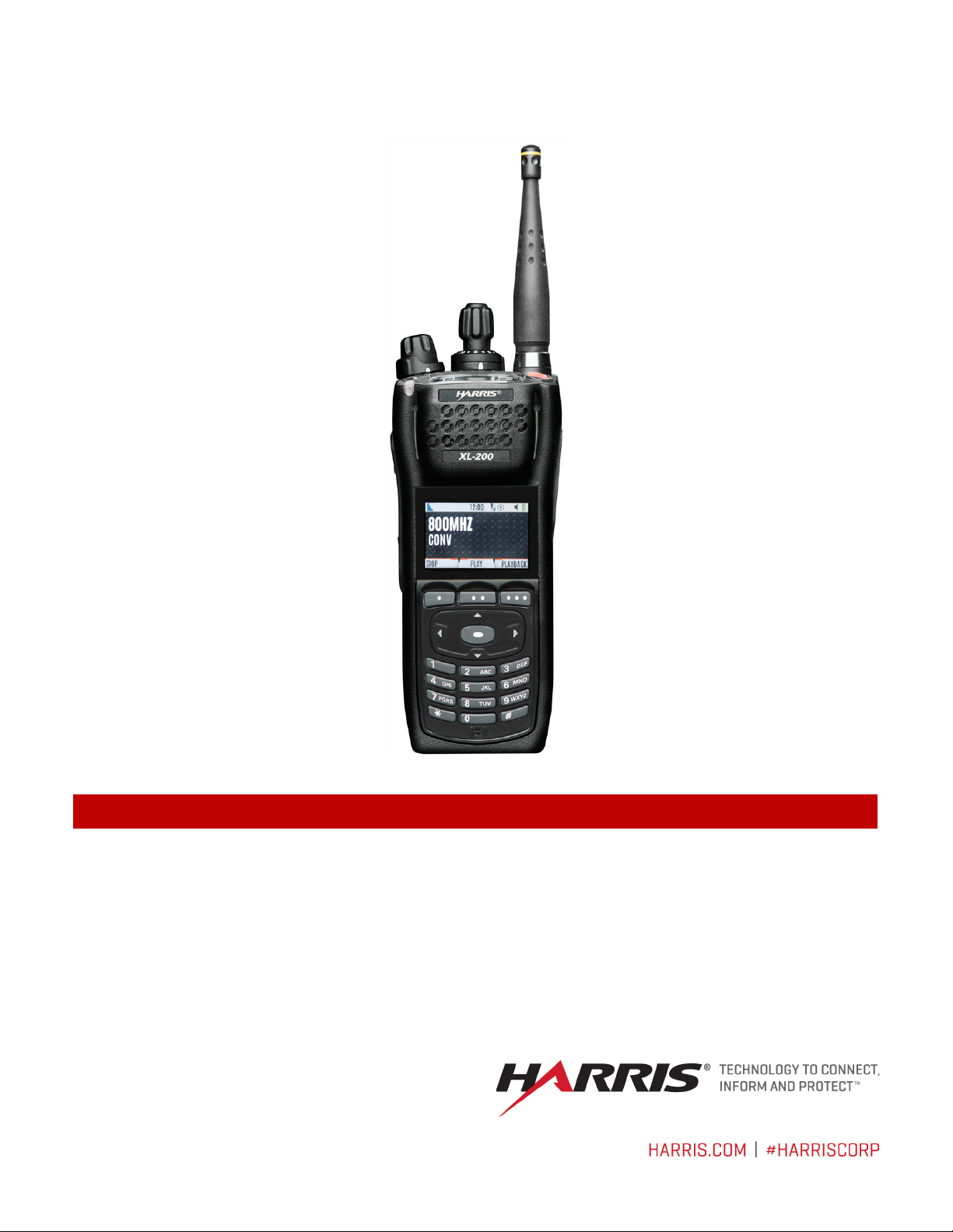
XL-200P Full-Spectrum Multiband
XL-185P Single Band
Portable Radios
14221-1800-2000, Rev. G
REV.
DATE
REASON FOR CHANGE
-
Sep/15
Initial release.
A
Sep/15
Added Section 3.
B
Nov/15
Added CE information.
Updated Declaration of Conformity. Added EU regulatory approval information (standards) and
EU RF exposure information.
Updated Table 1-1 and Tableau 2-1. Updated for XLP R2A. Added note to Section 4.3.1
regarding charging the battery before first use. Updated Appendix A. Updated Section 4.3.3.
Updated Sections 1.2, 4.1, 4.6, 5.8, 5.12, 10, included XLP R3A features, and added Sections
4.3.4, 5.35, and 5.6.
F
Apr/17
Updated to add XLP R4A features.
G
Jul/17
Added XL-185P, XLP R5A features, and C1D1 information.
MANUAL REVISION HISTORY
C Jan/16
D Jul/16
E Jan/17
ACKNOWLEDGEMENT
This product was developed using GEOTRANS, a product of the National Geospatial Intelligence Agency and U.S. Army Engineering
Research and Development C enter. Use of this software does not indicat e endorsement or approval of the product by the Secret ary of
Defense or the National Geospatial Intelligence Agency.
This device made under license under one or more of the following US patents: 4,590,473; 4,636,791; 5,148,482; 5,185,796; 5,271,017;
5,377,229; 4,71 6, 4 07; 4,972,460; 5,5 02,767; 5,146,6 97 ; 5,164,986; 5,185,795.
The Advanced Multi-Band Excitation implementation 2 (AMBE+2) voice coding Technology embodied in this product is protected by
intellectual property rights including patent rights, copyrights and trade secrets of Digital Voice Systems, Inc. This voice coding
Technology is licensed solely for use within this Communications Equipment. The user of this Technology is explicitly prohibited from
attempting to extract, re move, decompile, revers e engineer, o r disassemble the Ob ject Code, or in any other way convert the Object Code
into a human-readable form. U.S. Patent Nos. #5,870,405, #5,826,222, #5,754,974, #5,701,390, #5,715,365, #5,649,050, #5,630,011,
#5,581,656, #5, 517,511, #5,49 1,7 72, #5 ,247,579, #5,2 26, 084 and #5,195,16 6.
CREDITS
Harris, Unity, VIDA, EDACS, NetworkFirst, and OpenSky are registered trademarks of Harris Corporation. TECHNOLOGY TO
CONNECT, INFORM AND PROTECT is a trademark of Harris Corp orati on .
Bluetooth is a registered trademark of Bluetooth SIG, Inc.
Motorola is a registered trademark of Motorola, Inc.
AMBE is a registered trademark and IMBE, AMBE+, and AMBE+2 are trademarks of Digital Voice Systems, Inc.
Wi-Fi is a registered trademark of
All brand and product names are trademarks, register ed trademarks, or service marks of their respect ive holders.
The material contained herein is subject to U.S. export approval. No export or re-export is permitted without written approval from the U.S.
Government. Rated: EAR99; in accordance with U.S. Dept. of Commerce regulations 15CFR774, Export Administration Regulations.
Information and descriptions contained herein are the property of Harris Corporation. Such information and descriptions may not be copied
or reproduced by any means, or disseminated or distributed without the express prior written permission of Harris Corporation, PSPC
Business, 221 Jefferson Ridge Parkway, Lynchburg, VA 24501.
Repairs to this equipment should be made only by an authorized service technician or facility designated by the supplier. Any repairs,
alterations or substitutions of recommended parts made by the user to this equipment not approved by the manufacturer could void the
user's authority to operate the equipment in addition to the manufacturer's warranty.
Wi-Fi Alliance.
NOTICE!
This product conforms to the European Union WEEE Directive 2012/19/EU. Do not dispose of this product in a public
landfill. Take it to a recycling center at the end of its life.
Harris products comply with the Restriction of the Use of Certain Hazardous Substances in Electrical and Electronic
Equipment (RoHS) Directive.
This manual is published by Harris Corporation without any warranty. Improvements and changes to this manual necessitated by typographical errors,
inaccuracies of current information, or improvements to programs and/or equipment, may be made by Harris Corporation at any time and without notice.
Such changes will be incorporated into new editi ons of this manual. No part of this manual may be reproduced or transmitted in any form or by any means,
electronic or mechanical, including photocopying and recording, for any purpose, without the express written permission of Harris Corporation.
Copyright © 2015-2017 Harris Corporation.
2
14221-1800-2000, Rev. G
This device is a RF transceiver intended for land mobile radio applications. The device may have use restrictions, which requir e that the
national authority be contacted for any system licensing requirements, frequency use, allowable power level, etc.
3
14221-1800-2000, Rev. G
4

14221-1800-2000, Rev. G
DECLARATION OF CONFORMITY
Česky [Czech]
Harris Corporation tímto prohlašuje, že tento XL-200P je ve shodě se základními požadavky a
dalšími příslušnými ustanoveními směrnice 1999/5/ES.
væsentlige krav og øvrige relevante krav i direktiv 1999/5/EF.
Hiermit erklärt
dass sich das Gerät XL-200P in Übereinstimmung mit den
1999/5/EG befindet.
põhinõuetele ja nimetatud direktiivist tulenevatele teistele asjakohastele sätetele.
Hereby,
, declares that this
is in compliance with the essential
requirements and other relevant provisions of Directive 1999/5/EC.
Español
[Spanish]
Por medio de la presente Harris Corporation declara que el XL-200P cumple con los requisitos
esenciales y cualesquiera otras disposiciones aplicables o exigibles de la Directiva 1999/5/CE.
Ελληνική
[Greek]
ΜΕ ΤΗΝ ΠΑΡΟΥΣΑ Harris Corporation ΔΗΛΩΝΕΙ ΟΤΙ XL-200P ΣΥΜΜΟΡΦΩΝΕΤΑΙ ΠΡΟΣ ΤΙΣ
ΟΥΣΙΩΔΕΙΣ ΑΠΑΙΤΗΣΕΙΣ ΚΑΙ ΤΙΣ ΛΟΙΠΕΣ ΣΧΕΤΙΚΕΣ ΔΙΑΤΑΞΕΙΣ ΤΗΣ ΟΔΗΓΙΑΣ 1999/5/ΕΚ.
Français
[French]
Par la présente Harris Corporation déclare que l'appareil XL-200P est conforme aux exigences
essentielles et aux autres dispositions pertinentes de la directive 1999/5/CE.
essenziali ed alle altre disposizioni pertinenti stabilite dalla direttiva 1999/5/CE.
Latviski
[Latvian]
Ar šo Harris Corporation deklarē, XG 25P UHF-L (378-470 MHz), 7/800 (764-870MHz) atbilst
Direktīvas 1999/5/EK būtiskajām prasībām un citiem ar to saistītajiem noteikumiem.
Lietuvių
[Lithuanian]
Šiuo Harris Corporation deklaruoja, kad šis XL-200P atitinka esminius reikalavimus ir kitas
1999/5/EB Direktyvos nuostatas.
[Dutch]
essentiële eisen en de andere relevante bepalingen van richtlijn 1999/5/EG.
Malti [Maltese]
Hawnhekk, Harris Corporation, jiddikjara li dan XL-200P jikkonforma mal-ħtiġijiet essenzjali u ma
provvedimenti oħrajn relevanti li hemm fid-Dirrettiva 1999/5/EC.
Magyar
[Hungarian]
Alulírott, Harris Corporation nyilatkozom, hogy a XL-200P megfelel a vonatkozó alapvetõ
követelményeknek és az 1999/5/EC irányelv egyéb elõírásain ak.
Polski [Polish]
Niniejszym Harris Corporation oświadcza, że XL-200P jest zgodny z zasadniczymi wymogami
oraz pozostałymi stosownymi postanowieniami Dyrektywy 1999/5/EC.
[Portuguese]
outras disposições da Directiva 1999/5/CE.
[Slovenian]
izjavlja, da je ta
v skladu z bistvenimi zahtevami in ostalimi
relevantnimi določili direktive 1999/5/ES.
Slovensky
[Slovak]
Harris Corporation týmto vyhlasuje, že XL-200P spĺňa základné požiadavky a všetky príslušné
ustanovenia Smernice 1999/5/ES.
Suomi [Finnish]
Harris Corporation vakuuttaa täten että XL-200P tyyppinen laite on direktiivin 1999/5/EY
oleellisten vaatimusten ja sitä koskevien direktiivin muiden ehtojen mukainen.
[Swedish]
väsentliga egenskapskrav och övriga relevanta bestämmelser som framgår av direktiv 1999/5/EG.
[Icelandic]
kröfur, sem gerðar eru í tilskipun 1999/5/EC.
Norsk
[Norwegian]
Harris Corporation erklærer herved at utstyret XL-200P er i samsvar med de grunnleggende krav
og øvrige relevante krav i direktiv 1999/5/EF.
Dansk [Danish] Undertegnede Harris Corporation erklærer herved, at følgende uds tyr XL-200P overholder de
Deutsch
[German]
Eesti [Estonian]
English
Italiano [Italian] Con la presente Harris Corporation dichiara che questo XL-200P è conforme ai requisiti
Nederlands
grundlegenden Anforderungen und den übrigen einschlägigen Bestimmungen der Richtlinie
Käesolevaga kinnitab Harris Corporation seadme XL-200P
Hierbij verklaart Harris Corporation dat het toestel XL-200P in overeenstemming is met de
Harris Corporation,
Harris Corporation
vastavust direktiivi 1999/5/EÜ
XL-200P
Português
Slovensko
Svenska
Íslenska
Harris Corporation declara que este XL-200P está conforme com os requisitos essenciais e
Harris Corporation
Härmed intygar Harris Corporation att denna XL-200P står I överensstämmelse med de
Hér með lýsir Harris Corporation yfir því að XL-200P er í samræmi við grunnkröfur og aðrar
XL-200P
5

14221-1800-2000, Rev. G
Section Page
5.5.1 Top Display ................................................................................................................... 37
TABLE OF CONTENTS
1. REGULATORY AND SAFETY INFORMATION ........................................................................... 11
1.1 SAFETY CONVENTIONS ........................................................................................................ 11
1.2 SAFETY TRAINING INFORMATION .................................................................................... 11
1.2.1 RF Exposure Guidelines ................................................................................................ 12
1.2.2 Electromagnetic Interference/Compatibility .................................................................. 13
1.3 REGULATORY APPROVALS ................................................................................................. 14
1.3.1 Part 15 ............................................................................................................................ 14
1.3.2 Industry Canada ............................................................................................................. 14
1.4 OPERATING TIPS .................................................................................................................... 14
1.4.1 Efficient Radio Operation .............................................................................................. 14
1.4.2 Antenna Care and Replacement ..................................................................................... 14
1.4.3 Electronic Devices ......................................................................................................... 15
1.4.4 Aircraft ........................................................................................................................... 15
1.4.5 Electric Blasting Caps .................................................................................................... 15
1.4.6 Potentially Explosive Atmospheres ............................................................................... 15
2. RENSEIGNEMENTS SUR LA RÉGLEMENTATION ET SÉCURITÉ ....................................... 16
2.1 CONVENTIONS SUR LES SYMBOLES DE SÉCURITÉ ...................................................... 16
2.2 RENSEIGNEMENTS SUR LA FORMATION SUR LA SÉCURITÉ ...................................... 16
2.2.1 Directives sur l’exposition aux RF ................................................................................ 17
2.2.2 Interférence/Compatibilité Électr omagnétiqu e .............................................................. 18
2.3 INTERFÉRENCE DES RADIOFRÉQUENCES ....................................................................... 18
2.3.1 Partie 15 de la FCC ........................................................................................................ 18
2.3.2 Industrie Canada ............................................................................................................ 18
2.4 CONSEILS D’UTILISATION ................................................................................................... 18
2.4.1 Utilisation Efficace de la Radio ..................................................................................... 18
3. HAZARDOUS LOCATIONS .............................................................................................................. 21
3.1 CLASS 1, DIVISION 2 OPTION ............................................................................................... 21
3.2 CLASS 1, DIVISION 1 OPTION ............................................................................................... 22
4. INTRODUCTION ................................................................................................................................ 25
4.1 DESCRIPTION .......................................................................................................................... 25
4.2 STORAGE GUIDELINES ......................................................................................................... 25
4.3 BASIC SETUP ........................................................................................................................... 26
4.3.1 Assemble the Radio ....................................................................................................... 26
4.3.2 Removing the Battery .................................................................................................... 27
4.3.3 Removing the Optional Belt Clip or D-Post .................................................................. 27
4.3.4 Install the SIM Card ....................................................................................................... 28
4.4 UNIVERSAL DEVICE CONNECTOR ..................................................................................... 29
4.5 CLEANING ................................................................................................................................ 29
4.6 OPTIONS AND ACCESSORIES .............................................................................................. 30
4.7 RELATED PUBLICATIONS .................................................................................................... 33
5. BASIC OPERATION ........................................................................................................................... 34
5.1 RADIO CONTROLS .................................................................................................................. 34
5.2 SOFT DTMF KEYPAD ............................................................................................................. 36
5.3 BEFORE FIRST USE ................................................................................................................. 36
5.4 POWER ON AND SET VOLUME ............................................................................................ 37
5.5 RADIO DISPLAYS .................................................................................................................... 37
6

14221-1800-2000, Rev. G
Section Page
5.5.2 Front Display ................................................................................................................. 38
5.34 MDC-1200 (ANALOG CONVENTIONAL ONLY) ................................................................. 66
TABLE OF CONTENTS
5.6 MANDOWN............................................................................................................................... 40
5.7 STATUS MESSSAGES ............................................................................................................. 40
5.8 PREDEFINED MENU LAYOUTS............................................................................................ 41
5.9 MENU ........................................................................................................................................ 42
5.10 ALERT TONES.......................................................................................................................... 45
5.11 SELECT ZONE/SYSTEM ......................................................................................................... 46
5.12 SELECT GROUP/CHANNEL AND BANK ............................................................................. 47
5.13 LOCK/UNLOCK KEYPAD....................................................................................................... 47
5.14 GROUP CALLS ......................................................................................................................... 48
5.14.1 Transmit a Group Call ................................................................................................... 48
5.14.2 Receive a Group Call ..................................................................................................... 48
5.15 INDIVIDUAL CALLS ............................................................................................................... 49
5.15.1 Transmit an Individual Call ........................................................................................... 49
5.15.2 Receiving an Individual Call ......................................................................................... 49
5.16 USER PROFILES ....................................................................................................................... 50
5.17 NOISE CANCELLATION ......................................................................................................... 51
5.17.1 Enable Noise Cancellation ............................................................................................. 51
5.17.2 Using Noise Cancellation .............................................................................................. 52
5.17.3 The Effect of Distance from the Microphone ................................................................ 52
5.17.4 Primary versus Secondary Microphone ......................................................................... 52
5.17.5 When using an SCBA Mask .......................................................................................... 52
5.18 PTT OPTIONS ........................................................................................................................... 53
5.19 VOICE ANNUNCIATION ........................................................................................................ 53
5.20 ENABLE/DISABLE ENCRYPTION ........................................................................................ 54
5.21 TRANSMIT ENABLE/DISABLE ............................................................................................. 54
5.22 CHANNEL GUARD (ANALOG CONVENTIONAL ONLY) ................................................. 55
5.23 USE TALKAROUND TO BYPASS REPEATER (ANALOG AND P25 CONVENTIONAL
ONLY) ........................................................................................................................................ 56
5.24 TYPE 99 OPERATION .............................................................................................................. 57
5.24.1 Enable /Di sab le Type 99 ................................................................................................. 57
5.24.2 Disable After PTT.......................................................................................................... 58
5.24.3 Auto Reset ..................................................................................................................... 58
5.25 CALL ALERT (PAGE) .............................................................................................................. 58
5.25.1 Send Alert ...................................................................................................................... 58
5.25.2 Receive Alert ................................................................................................................. 58
5.26 DTMF ......................................................................................................................................... 58
5.27 AUDIO PLAYBACK ................................................................................................................. 59
5.28 START SCAN ............................................................................................................................ 60
5.29 STOP SCAN ............................................................................................................................... 61
5.30 MONITOR AND SQUELCH TYPES (CONVENTIONAL ONLY) ........................................ 62
5.31 NUISANCE DELETE ................................................................................................................ 63
5.32 CONVENTIONAL FAILSOFT (EDACS ONLY) .................................................................... 64
5.33 EMERGENCY OPERATION .................................................................................................... 65
5.33.1 Declaring an Emergency Call ........................................................................................ 65
5.33.2 Receiving an Emergency Call ....................................................................................... 65
5.33.3 Stealth Emergency ......................................................................................................... 66
7

14221-1800-2000, Rev. G
Section Page
5.34.1 Normal PTT Operation .................................................................................................. 66
6.20.7 Delete I ndiv idual Key s .................................................................................................. 95
TABLE OF CONTENTS
5.34.2 MDC PTT ID Receive Handling ................................................................................... 66
5.34.3 Emergency Declaration ................................................................................................. 66
5.35 BEON OPERATION .................................................................................................................. 67
6. ADVANCED OPERATIONS .............................................................................................................. 68
6.1 VIEW/CHANGE PERSONALITIES ......................................................................................... 68
6.2 SITUATIONAL AWARENESS (SA) – P25 CONVENTIONAL ONLY ................................. 70
6.3 USER-DEFINED ZONES/SYSTEMS ....................................................................................... 71
6.4 CH INFO MENU ........................................................................................................................ 73
6.5 AUDIO SETTINGS .................................................................................................................... 73
6.6 DISPLAY SETTINGS ................................................................................................................ 74
6.7 GPS SETTINGS ......................................................................................................................... 76
6.8 POSITION INFO ........................................................................................................................ 76
6.9 WI-FI .......................................................................................................................................... 77
6.10 BLUETOOTH ............................................................................................................................ 78
6.11 CLOCK SETTINGS ................................................................................................................... 80
6.12 BATTERY INFO ........................................................................................................................ 80
6.13 SELECT LANGUAGE............................................................................................................... 81
6.14 SET UP SCAN ........................................................................................................................... 81
6.15 RADIO STATUS ........................................................................................................................ 87
6.16 RADIO MESSAGE .................................................................................................................... 88
6.17 RADIO TEXTLINK ................................................................................................................... 89
6.18 FAULTS/ALERTS ..................................................................................................................... 91
6.19 TONE ENCODE ........................................................................................................................ 92
6.20 ENCRYPTION ........................................................................................................................... 93
6.1.1 View Personalities ......................................................................................................... 68
6.1.2 Change Active Personality ............................................................................................ 69
6.3.1 Command Tactical Zone ................................................................................................ 71
6.3.2 Mixed System Zone ....................................................................................................... 72
6.10.1 Enable Bluetooth ........................................................................................................... 78
6.10.2 Pair Devices ................................................................................................................... 79
6.14.1 Default, Priority 1, and Priority 2 Channels .................................................................. 82
6.14.2 Trunked/Conventional Scanning ................................................................................... 82
6.14.3 Vote Scan (Analog and P25 Conventional Only) .......................................................... 83
6.14.4 Edit Scan List ................................................................................................................. 83
6.14.5 Set or Remove Priority 1 and Priority 2 Channels ......................................................... 84
6.14.6 Custom Scan Lists ......................................................................................................... 85
6.14.7 Wide Area System Scan (P25 Trunked and EDACS) ................................................... 87
6.17.1 Radio TextLink Messages ............................................................................................. 90
6.17.2 Radio TextLink Form s ................................................................................................... 90
6.17.3 View Received Messages .............................................................................................. 91
6.20.1 Create and Load Keys .................................................................................................... 93
6.20.2 Zeroize Keys from Radio ............................................................................................... 93
6.20.3 Protect ed Key s ............................................................................................................... 93
6.20.4 Global Encryption .......................................................................................................... 94
6.20.5 Select Key se t ................................................................................................................. 95
6.20.6 View Key List ................................................................................................................ 95
8

14221-1800-2000, Rev. G
Section Page
6.20.8 OTAR Configuration ..................................................................................................... 96
LIST OF FIGURES
Page
Figure 4-1: Radio Assembly .......................................................................................................................... 26
TABLE OF CONTENTS
6.21 SITE ALIAS AND SITE LOCK (P25 TRUNKED ONLY) ...................................................... 96
7. PROGRAMMING ................................................................................................................................ 97
7.1 PROGRAMMING VIA RPM2 .................................................................................................. 97
7.2 EDIT CHANNEL (ANALOG AND P25 CONVENTIONAL ONLY) ..................................... 97
7.3 OTAP .......................................................................................................................................... 99
7.4 PROGRAMMABLE BUTTONS AND SWITCHES ................................................................. 99
7.4.1 Programmable Buttons .................................................................................................. 99
7.4.2 Programmable A/B (Ø/O) Switch ............................................................................... 101
7.4.3 Programmable A/B/C/D Switch .................................................................................. 101
7.5 PROGRAMMABLE ICONS .................................................................................................... 102
7.5.1 Top display .................................................................................................................. 102
7.5.2 Front display ................................................................................................................ 103
8. REFERENCE ...................................................................................................................................... 105
8.1 MARINE FREQUENCIES ...................................................................................................... 105
8.2 NARROWBANDING .............................................................................................................. 110
9. GLOSSARY ........................................................................................................................................ 111
10. BASIC TROUBLESHOOTING ........................................................................................................ 114
10.1 ERROR MESSAGES ............................................................................................................... 114
10.2 OTAR ERRORS/INFORMATION .......................................................................................... 115
11. TECHNICAL ASSISTANCE ............................................................................................................ 116
12. WARRANTY ...................................................................................................................................... 116
APPENDIX A WI-FI PROGRAMMING ......................................................................................... 117
Figure 4-2: Remove the Battery ..................................................................................................................... 27
Figure 4-3: Remove Belt Clip ........................................................................................................................ 27
Figure 4-4: SIM Card Installation .................................................................................................................. 28
Figure 4-5: Universal Device Connector ....................................................................................................... 29
Figure 5-1: Radio Controls ............................................................................................................................ 34
Figure 5-2: Using the Soft DTMF Keypad .................................................................................................... 36
Figure 5-3: Top Display ................................................................................................................................. 37
Figure 5-4: Sample Idle Front Display .......................................................................................................... 38
Figure 5-5: Using Noise Cancellation ............................................................................................................ 52
Figure 6-1: Enabling Wi-Fi ............................................................................................................................ 77
Figure 6-2: Wi-Fi Install Active ..................................................................................................................... 78
Figure A-1: Options Network Configuration .......................................................................................... 118
Figure A-2: Wi-Fi Configuration ................................................................................................................. 118
Figure A-3: Service Name ........................................................................................................................... 119
Figure A-4: Enable Wi-Fi in RPM2 ............................................................................................................. 119
Figure A-5: Enable Wi-Fi Programming Mode on Radio ........................................................................... 120
Figure A-6: RPM2 Radio Tab: Wi-Fi .......................................................................................................... 121
9

14221-1800-2000, Rev. G
LIST OF TABLES
Page
Table 1-1: RF Exposure Compliance Tested Distances (Worst Case Scenario) ............................................ 12
Table 1-2: Simultaneous Transmission Scenarios ......................................................................................... 13
Tableau 2-1 : Distances de test de conformité des expositions aux RF (pire des scénarios) ......................... 17
Table 4-1: Options and Accessories ............................................................................................................... 30
Table 5-1: Radio Controls, Indicators, and Connectors ................................................................................. 34
Table 5-2: Radio Icons ................................................................................................................................... 38
Table 5-3: Status Messages ............................................................................................................................ 40
Table 5-4: Predefined Menu Layouts ............................................................................................................. 41
Table 5-5: Menu Navigation ......................................................................................................................... 42
Table 5-6: Alert Tones ................................................................................................................................... 45
Table 7-1: Valid Frequency Ranges ............................................................................................................... 99
Table 7-2: Programmable Button Options ................................................................................................... 100
Table 7-3: Programmable Ø/O Switch Options ........................................................................................... 101
Table 7-4: Single-Instance Features ............................................................................................................. 101
Table 7-5: Indexed Features ......................................................................................................................... 102
Table 8-1: Marine Frequencies .................................................................................................................... 105
Table 10-1: Displayed Error Messages, Reasons, and Resolutions ............................................................ 114
Table 12-1: Wi-Fi Feature Support .............................................................................................................. 121
Harris Corporation, Public Safety and Professional Communications (PSPC) Business continually evaluates its techn ical publications for
completeness, technical accuracy, and organization. You can assist in this process by submitting your comments and suggestions to the
following:
Harris Corporation fax your comments to: 1-434-455-6851
PSPC Business or
Technical Publications e-mail us at: PSPC_TechPubs@harris.com
221 Jefferson Ridge Parkway
Lynchburg, VA 24501
10
14221-1800-2000, Rev. G
The WARNING symbol calls attention to a procedure, practice, or the like, which, if
not correctly performed or adhered to, could result in personal injury. Do not
proceed beyond a WARNING symbol until the conditions identified are fully
understood or met.
The Harris XL-200P/XL-185P portable radio generates RF electromagnetic energy
ed only during the course of employment by
individuals aware of the hazards and the ways to minimize such hazards. This
radio is NOT intended for use by the “General Population” in an uncontrolled
environment.
WARNING
CAUTION
NOTE
WARNING
1. REGULATORY AND SAFETY INFORMATIO N
1.1 SAFETY CONVENTIONS
The following conventions are used throughout this manual to alert the user to general safety precautions
that must be observed during all phases of operation, service, and repair of this product. Failure to comply
with these precautions or with specific warning elsewhere in this manual violates safety standards of
design, manufacture, and intended use of the product. Harris assumes no liability for the customer’s
failure to comply with these standards.
The CAUTION symbol calls attention to an operating procedure, practice, or the like,
which, if not performed correctly or adhered to, could result in damage to the equipment
or severely degrade the equipment performance.
The NOTE symbol calls attention to supplemental information, which may improve
system performance or clarify a process or procedure.
1.2 SAFETY TRAINING INFORMATION
during transmit mode. This radio is designed for and classified as “Occupational
Use Only,” meaning it must be us
The XL-200P/XL-185P portable radio has been tested and complies with the FCC RF exposure limits for
“Occupational Use Only.” In addition, this Harris radio complies with the following Standards and
Guidelines with regard to RF energy and electromagnetic energy levels and evaluation of such levels for
exposure to humans:
• FCC KDB Publication 447498 General RF Exposure Guidance
• American National Standards Institute (C95.1 – 1992
Respect to Human Exposure to Radio Frequency Electromagnetic Fields, 3 kHz to 300 GHz.
• American National Standards Institute (C95.3 – 1992), IEEE Recommended Practice for the
Measurement of Potentially Hazardous Electromagnetic Fields – RF and Microwave.
1
), IEEE Standard for Safety Levels with
• IC Standard RSS-102. Radiofrequency Exposure Compliance of Radiocommunication Apparatus
(All Frequency Bands).
• European Council Directive 89/391/EEC.
1
Tested to ANSI C95.1-1992 in compliance with 47 CFR 2.1093. Meets or exceeds safety requirements of ANSI C95.1-2005.
11

14221-1800-2000, Rev. G
CAUTION
1.2.1 RF Exposure Guidelines
To ensure that exposure to RF electromagnetic energy is within the EU/AU/FCC/IC
allowable limits for occupational use, always adhere to the following guidelines:
• DO NOT operate the radio without a proper antenna attached, as this may damage the radio and may
also cause the FCC RF exposure limits to be exceeded. A proper antenna is the antenna supplied with
this radio by Harris or an antenna specifically authorized by Harris for use with this radio. (Refer to
Table 4-1.)
• DO NOT transmit for more than 50% of total radio use time (“50% duty cycle”). Transmitting more
than 50% of the time can cause FCC RF exposure compliance requirements to be exceeded. The radio
is transmitting when the “TX” indicator appears in the display. The radio will transmit by pressing the
“PTT” (Push-To-Talk) button.
• ALWAYS transmit using low power when possible. In addition to conserving battery charge, low
power can reduce RF exposure.
• ALWAYS use Harris authorized accessories (antennas, batteries, belt clips, speaker/mics, etc.). Use
of unauthorized accessories may cause the FCC Occupational/Controlled Exposure RF compliance
requirements to be exceeded. (Refer to Table 1-1.)
• As noted in Table 1-1, ALWAYS keep the housing of the transmitter AT LEAST 0.47 inches (1.2
cm) from the body and at least 0.98 in (2.5 cm) from the face when transmitting to ensure
EU/AU/FCC/IC RF exposure compliance requirements are not exceeded. However, to provide the
best sound quality to the recipients of your transmission, Harris recommends you hold the
microphone at least 2 in (5 cm) from mouth, and slightly off to one side.
• Refer to Standard EN 62311:2008.
Table 1-1: RF Exposure Compliance Tested Distances (Worst Case Scenario)
RADIO FREQUENCY Body2 Face
VHF
(136 - 174 MHz)
UHF
(378 - 522 MHz)
700/800 MHz
(768 - 776 MHz)
(798 - 806 MHz)
(806 - 824 MHz)
(851 - 870 MHz)
900 MHz
(935-944 MHz)
(896-902 MHz)
2400 MHz
(2412 - 2472 MHz)
5 GHz
(5.18 - 5.825 GHz)
0.47 in (1.2 cm) 0.98 in (2.5 cm)
0.47 in (1.2 cm) 0.98 in (2.5 cm)
0.47 in (1.2 cm) 0.98 in (2.5 cm)
0.47 in (1.2 cm) 0.98 in (2.5 cm)
0.47 in (1.2 cm) 0.98 in (2.5 cm)
0.47 in (1.2 cm) 0.98 in (2.5 cm)
2
12
This is worst case based on the thinnest body mount accessory (belt clip).

14221-1800-2000, Rev. G
YES
YES
YES
YES
YES
YES
YES
YES
YES
YES
YES
YES
YES
YES
YES
YES
YES
YES
YES
YES
YES
YES
YES
YES
YES
YES
YES
YES
YES
YES
NOTE
NOTE
NOTE
SAR Evaluation: 1g averaged, 50% PTT Duty Factor, Occupational/Controlled Exposure.
This device contains multiple transmitters that may operate simultaneously, see Table 1-2 Simultaneous
Transmission Scenarios for the capable transmit configurations.
Table 1-2: Simultaneous Transmission Scenarios
NO. CAPABLE TRANSMIT CONFIGURATION HEAD
1 LTE B13/14/4 + VHF
2 LTE B13/14/4 + UHF
3 LTE B14 + 800 MHz
4 LTE B13/14/4 + Bluetooth
5 LTE B13/14/4 + 2.4 GHz WLAN
6 LTE B13/14/4 + 5 GHz WLAN
7 LTE B13/14/4 + VHF + Bluetooth
8 LTE B13/14/4 + UHF + Bluetooth
9 LTE B14 + 800 MHz + Bluetooth
10 LTE B13/14/4 + VHF + WLAN
11 LTE B13/14/4 + UHF + WLAN
12 LTE B14 + 800 MHz + WLAN
13 LTE B13/14/4 + 900 MHz (XL-185P Only)
14 LTE B13/14/4 + 900 MHz + Bluetooth
15 LTE B13/14/4 + 900 MHz + WLAN
LTE B13/14/4 + 700 MHz simultan eous tr ansmission is not supported by this device.
LTE B13/4 + 800 MHz simultaneous transmission is not supported by
BODY-WORN
ACCESSORY
LTE is not supported by the XL Portable with the C1D1 option.
The information in this section provides the information needed to make the user aware of RF exposure,
and what to do to assure that this radio operates within the FCC RF exposure limits.
1.2.2 Electromagnetic Interference/Compatibility
During transmissions, this Harris radio generates RF energy that can possibly cause interference with
other devices or systems. To avoid such interference, turn off the radio in areas where signs are posted to
do so. DO NOT operate the transmitter in areas that are sensitive to electromagnetic radiation such as
hospitals, aircraft, and blasting sites.
13
14221-1800-2000, Rev. G
Do not use the portable radio with a damaged or missing antenna. A minor burn
may result if a damaged antenna comes into contact with the skin. Replace a
damaged antenna immediately. Operating a portable radio with the antenna missing
WARNING
WARNING
1.3 REGULATORY APPROVALS
Changes or modifications not expressly approved by the manufacturer could void the user’s authority to
operate the equipment.
1.3.1 Part 15
This device complies with Part 15 of the FCC Rules. Operation is subject to the following two conditions:
1. This device may not cause harmful interference, and
2. This device must accept any interference received, including interference that may cause undesired
operation.
1.3.2 Industry Canada
This device complies with Industry Canada license-exempt RSS standard(s). Operation is subject to the
following two conditions: (1) this device may not cause interference, and (2) this device must accept any
interference, including interference that may cause undesired operation of the device.
1.4 OPERATING TIPS
Antenna location and condition are important when operating a portable radio. Operating the radio in
low-lying areas or terrain, under power lines or bridges, inside of a vehicle, or in a metal framed building
can severely reduce the range of the unit. Mountains can also reduce the range of the unit.
In areas where transmission or reception is poor, some improvement may be obtained by ensuring that the
antenna is vertical. Moving a few yards in another direction or moving to a higher elevation may also
improve communications. Vehicular operation can be aided with the use of an externally mounted
antenna.
Battery condition is another important factor in the trouble-free operation of a portable radio. Always
properly charge the battery.
1.4.1 Efficient Radio Operation
Keep the antenna in a vertical position when receiving or transmitting a message.
Do NOT hold onto the antenna when the radio is powered on!
1.4.2 Antenna Care and Replacement
could cause personal injury, damage the radio, and may violate FCC regulations.
14
14221-1800-2000, Rev. G
Use only the supplied or approved antenna. Unauthorized antennas, modifications, or
RF energy from portable radios may affect some electronic equipment. Most modern
Areas with potentially explosive atmospheres are often, but not always, clearly
CAUTION
CAUTION
WARNING
WARNING
WARNING
attachments could cause damage to the radio unit and may violate FCC regulations. (Refer
to Table 4-1.)
1.4.3 Electronic Devices
electronic equipment in cars, hospitals, homes, etc. is shielded from RF energy. However,
in areas in which you are instructed to turn off two-way radio equipment, always observe
the rules. If in doubt, turn it off!
1.4.4 Aircraft
• Always turn off a portable radio before boarding any aircraft!
• Use it on the ground only with crew permission.
• DO NOT use while in-flight!!
1.4.5 Electric Blasting Caps
To prevent accidental detonation of electric blasting caps, DO NOT use two-way
radios within 1000 feet of blasting operations. Always obey the "Turn Off Two-Way
Radios" signs posted where electric blasting caps are being used (OSHA Standard:
1926.900).
1.4.6 Potentially Explosive Atmospheres
marked. These may be fueling areas, such as gas stations, fuel or chemical transfer
or storage facilities, and areas where the air contains chemicals or particles, such as
grain, dust, or metal powders.
Sparks in such areas could cause an explosion or fire resulting in bodily injury or
even death.
Turn off two-way radios when in any area with a potentially explosive atmosphere. It
is rare, but not impossible that a radio or its accessories could generate sparks.
15
14221-1800-2000, Rev. G
Le symbole MISE EN GARDE attire l’attention sur une procédure ou une
qui, si elle n’est pas correctement effectuée ou observée, pourrait
MISE EN GARDE avant que les conditions identifiées soient complètement
opérationnelle qui, si elle n’est pas correctement effectuée ou observée, pourrait
t de l’énergie
MISE EN GARDE
AVERTISSEMENT
REMARQUE
MISE EN GARDE
2. RENSEIGNEMENTS SUR LA RÉGLEMENTATI O N ET
SÉCURITÉ
2.1 CONVENTIONS SUR LES SYMBOLES DE SÉCURI TÉ
Les conventions suivantes sont utilisées dans le présent manuel pour avertir l’utilisateur des précautions générales de
sécurité qui doivent être observées pendant toutes les phases d’opération, d’entretien et de réparation de ce produit.
Le non-respect de ces précautions ou d’avertissements précisés ailleurs enfreint les normes de sécurité de la
conception, de la fabrication et de l’utilisation prévue du produit. Harris n’assume aucune responsabilité pour le
non-respect de ces normes par le client.
pratique
entraîner une blessure personnelle. Ne pas poursuivre au-delà d’un symbole de
comprises ou satisfaites.
Le symbole AVERTISSEMENT attire l’attention sur une procédure ou une pratique
entraîner un bris d’équipement ou une importante baisse de rendement de l’équipement.
Le symbole REMARQUE attire l’attention sur des renseignements supplémentaires qui
peuvent améliorer le rendement du système ou clarifier un processus ou une procédure.
2.2 RENSEIGNEMENTS SUR LA FORM ATIO N S UR LA SÉCURITÉ
La radio portative Harris XL-200P/XL-185P produi
électromagnétique des RF lorsqu’en mode de transmission. Cette radio est conçue
et classée pour une « Utilisation professionnelle seulement », ce qui signifie qu’elle
ne doit être utilisée que dans le cadre d’un emploi par des individus conscient s des
risques et des moyens de limiter ceux-ci. Cette radio N’EST PAS conçue pour une
utilisation par la « Population générale » dans un environnement non contrôlé.
La radio portative XL-200P/XL-185P a été testée et est conforme aux limites d’exposition aux RF de la
FCC pour une « Utilisation professionnelle seulement ». De plus, cette radio Harris est conforme aux
normes et directives suivantes quant à l’énergie des RF et aux niveaux d’énergie électromagnétique, ainsi
qu’à l’évaluation de ces niveaux pour l’exposition aux humains:
• FCC KDB 447498
• American National Standards Institute (C95.1 – 1992), norme de l’IEEE sur les niveaux sécuritaires
d’exposition humaine aux champs électromagnétiques des radiofréquences, 3 kHz à 300 GHz.
• American National Standards Institute (C95.3 – 1992), pratique recommandée par l’IEEE pour la
mesure des champs électromagnétiques potentiellement dangereux – RF et micro-ondes.
16

14221-1800-2000, Rev. G
AVERTISSEMENT
2.2.1 Directives sur l’exposition aux RF
Pour s’assurer que l’exposition à l’énergie électromagnétique des RF se situe dans les
limites acceptables de la FCC pour l’utilisation professionnelle, respectez toujours les
directives suivantes :
• N’utilisez PAS la radio sans qu’une antenne appropriée y soit connectée, car ceci peut endommager la
radio et également causer un dépassement des limites d’exposition aux RF de la FCC. Une antenne
appropriée est celle fournie par Harris avec cette radio, ou une antenne spécifiquement autorisée par
Harris pour être utilisée avec cette radio. (Reportez-vous à Tableau 2-1.)
• Ne transmettez PAS pendant plus de 50 % de la durée d’utilisation totale de la radio (« cycle de
service de 50 % »). La transmission pendant plus de 50 % du temps peut causer un dépassement des
exigences de conformité de la FCC en matière d’exposition aux RF. La radio transmet lorsque
l’indicateur « TX » apparaît sur l’affichage. La radio transmet lorsqu’on appuie sur le bouton « PTT »
(bouton de microphone).
• Transmettez TOUJOURS en basse puissance lorsque possible. En plus de préserver la charge de la
pile, une faible puissance réduit l’exposition aux RF.
• Utilisez TOUJOURS des accessoires autorisés Harris (antennes, piles, pinces de ceinture, haut-
parleurs/micros, etc.). L’utilisation d’accessoires non autorisés peut entraîner un dépassement des
exigences de conformité pour une exposition aux RF professionnelle ou contrôlée de la FCC.
(Reportez-vous à Table 4-1.)
• Tel qu’indiqué dans Tableau 2-1, conservez TOUJOURS l’appareil et son antenne à AU MOINS
1,2 cm du corps, et à au moins 2,5 cm du visage pendant la transmission, pour vous assurer de ne pas
dépasser les exigences de conformité de la FCC en matière d’exposition aux RF. Cependant, pour
offrir la meilleure qualité sonore aux auditeurs de votre transmission, Harris recommande de tenir le
microphone à au moins 5 cm (2 po) de votre bouche et légèrement déplacé sur un côté.
Tableau 2-1 : Distances de test de conformité des expositions aux RF (pire des scénarios)
RADIOFRÉQUENCES
VHF
(136 - 174 MHz)
UHF
(378 - 522 MHz)
700/800 MHz
(768 - 776 MHz)
(798 - 806 MHz)
(806 - 824 MHz)
(851 - 870 MHz)
900 MHz
(935-944 MHz)
(896-902 MHz)
2400 MHz
(2412 - 2472 MHz)
Corps3 Visage
1,2 cm 2,5 cm
1,2 cm 2,5 cm
1,2 cm 2,5 cm
1,2 cm 2,5 cm
1,2 cm 2,5 cm
3
Ce est le pire des cas basée sur le corps plus mince monter accessoire (clip ceinture).
17

14221-1800-2000, Rev. G
RADIOFRÉQUENCES
Corps3
Visage
5 GHz
(5.18 - 5.825 GHz)
1,2 cm 2,5 cm
Dans cette section figurent les renseignements nécessaires pour sensibiliser l’utilisateur à l’exposition aux
RF et sur ce qu’il faut faire pour s’assurer que cette radio fonctionne dans les limites d’exposition aux RF
de la FCC.
2.2.2 Interférence/Compatibilité Électromagnétique
Pendant les transmissions, cette radio Harris produit de l’énergie des RF qui peut causer de l’interférence
avec d’autres appareils ou systèmes. Pour éviter de telles interférences, fermez la radio dans les zones où
il est indiqué de le faire. N’utilisez PAS le transmetteur dans des zones sensibles aux radiations
électromagnétiques, com me les hôp itaux , les av ions et les sites de détonat ion.
2.3 INTERFÉRENCE DES RADIOFRÉQUENCES
2.3.1 Partie 15 de la FCC
Cet appareil est conforme à la Partie 15 de la réglementation de la FCC. Le fonctionnement est soumis
aux deux conditions suivantes :
1. Cet appareil ne doit pas causer une interférence nuisible; et
2. Cet appareil doit accepter toute interférence reçue, y compris une interférence qui peut causer un
fonctionnement non souhaité.
2.3.2 Industrie Canada
Le présent appareil est conforme aux CNR d'Industrie Canada applicables aux appareils radio exempts de
licence. L'exploitation est autorisée aux deux conditions suivantes : (1) l'appareil ne doit pas produire de
brouillage, et (2) l'utilisateur de l'appareil doit accepter tout brouillage radioélectrique subi, même si le
brouillage est susceptible d'en com p rom ettre le fonc tionnement.
2.4 CONSEILS D’UTILIS ATION
L’emplacement et l’état de l’antenne sont importants pour l’utilisation d’une radio portative. L’utilisation
de la radio dans des zones de faible élévation, sous des lignes électriques ou des ponts, à l’intérieur d’un
véhicule ou dans un immeuble à ossature métallique, peut réduire la portée de l’appareil de manière
considérable. Les montagnes peuvent également réduire la portée de l’unité.
Dans les zones où la transmission ou la réception est insatisfaisante, certaines améliorations peuvent être
obtenues en s’assurant que l’antenne est verticale. Se déplacer de quelques mètres dans une autre
direction ou à un emplacement plus élevé peut également améliorer les communications. L’utilisation
d’une antenne fixée à l’extérieur peut faciliter le fonctionnement dans un véhicule.
L’état de la pile est un autre facteur important d’une utilisation sans tracas d’une radio portative. Chargez
toujours correctement la pile.
2.4.1 Utilisation Efficace de la Radio
Gardez l’antenne dans une position verticale pendant la réception ou la transmission d’un message.
18
14221-1800-2000, Rev. G
N’utilisez pas la radio portative si son antenne est endommagée ou absente. Une
légère peut se produire au contact d’une antenne endommagée avec la
peau. Remplacez immédiatement une antenne endommagée. L’utilisation d’une
radio portative alors que l’antenne est absente peut causer des blessures,
modifications ou des ajouts à une antenne peuvent endommager la radio et enfreindre la
L’énergie des RF provenant de radios portatives peut affecter certains appareils
électroniques. La majorité de l’équipement électronique moderne dans les voitures, les
où l’on vous demande de fermer l’équipement de radio bidirectionnelle, respectez toujours
MISE EN GARDE
MISE EN GARDE
AVERTISSEMENT
AVERTISSEMENT
MISE EN GARDE
MISE EN GARDE
Ne tenez PAS l’antenne lorsque la radio est allumée!
2.4.1.1 Entretien Et Remplacement De L’antenne
brûlure
endommager la radio et pourrait enfreindre la réglementation de la FCC.
Utilisez seulement l’antenne fournie ou une antenne approuvée. Des antennes non autorisées, des
réglementation de la FCC. (Reportez-vous à Table 4-1.)
2.4.1.2 Appareils Électroniques
hôpitaux, les maisons, etc. est blindé contre l’énergie des RF. Cependant, dans les zones
les règles. En cas de doute, éteignez-le!
2.4.1.3 Avion
• Éteignez toujours une radio portative avant d’embarquer à bord d’un avion!
• Ne l’utilisez au sol qu’avec la permission de l’équipage.
• NE l’utilisez PAS durant le vol!
2.4.1.4 Détonateurs Électriques
Pour prévenir la détonation accidentelle des détonateurs électriques, n’utilisez PAS
de radios bidirectionnelles à moins de 305 m (1 000 pi) des opérations de détonation.
Respectez toujours les indications « Éteindre les radios bidirectionnelles » situées là
où des détonateurs électriques sont utilisés. (Norme OSHA : 1926.900)
19

14221-1800-2000, Rev. G
en carburant, comme les postes d’essence, les installations de stockage ou de
ansfert de carburant ou de produits chimiques, ainsi que les zones dont l’air
Éteignez les radios bidirectionnelles dans toute zone ayant une atmosphère
potentiellement explosive. Il est rare, mais pas impossible qu’une radio ou ses
MISE EN GARDE
2.4.1.5 Atmosphère Potentiellement Explosive
Les zones ayant une atmosphère potentiellement explosive sont souvent, mais pas
toujours, identifiées clairement comme telles. Il peut s’agir de zones d’alimentation
tr
contient des produits chimiques ou des particules, comme des grains, de la poussière
ou des poudres métalliques.
Des étincelles dans de telles zones peuvent provoquer une explosion ou un incendie,
causant ainsi des blessures ou même la mort.
accessoires produisent des étincelles.
20
14221-1800-2000, Rev. G
EXPLOSION HAZARD – REPLACE BATTERY PACK ONLY IN AN AREA
PART NO.
LES BATTERIES DOIVENT
SEULEMENT, ET SEULEMENT AVEC UNE BATTERIE HARRIS PORTANT
LE NUMÉRO DE PIÈCE 14035-4010-01.
EXPLOSION HAZARD – Substitution of any component m ay impair suitability for
Une substitution de toute
composante pourrait compromettre la convenance pour la Classe I, Division 2.
mum battery charging current of
01 only. Use of another battery may present a risk of fire or
ended coil antenna and
carrying case option, only the following Harris accessories may be used with this
PART NUMBER
DESCRIPTION
12082-0600-01
Speaker Microphone
12082-0600-02
Speaker Microphone, Emergency Button
12082-0650-01
Microphone, Palm,2 Wire, Black
12082-0650-02
Microphone, Palm, 2 Wire, Beige
12082-0650-03
Microphone, Mini-Lapel,3 Wire, Black
12082-0650-04
Microphone, Mini-Lapel,3 Wire, Beige
12082-0650-05
Earphone Kit, Black
12082-0650-06
Earphone Kit, Beige
WARNING
WARNING
WARNING
WARNING
WARNING
3. HAZARDOUS LOCATIONS
3.1 CLASS 1, DIVISION 2 OPTION
Radios ordered with the Class 1, Division 2 option are suitable for use in Class 1, Division 2, Groups A,
B, C, and D or non-hazardous (unclassified) locations only.
Les radios commandées avec l’option Classe 1, Division 2 sont adéquates pour utilisation en Classe 1,
Division 2, Groupes A, B, C et D, ou en lieux non-hasardeux (non-classifiés) seulement
KNOWN TO BE NON-HAZARDOUS, AND ONLY WITH HARRIS
14035-4010-01.
AVERTISSEMENT – RISQUE D’EXPLOSION –
ÊTRE REMPLACÉES DANS UNE ZONE RECONNUE NON-HASARDEUSE
Class I, Division 2.
AVERTISSEMENT – RISQUE D’EXPLOSION –
EXPLOSION HAZARD – Do not exceed maxi
5.250 A or maximum charging voltage of 12.0 V DC at any time.
CAUTION - The battery used in this device may present a risk of fire or explosion
when heated above 100°C (212°F) or incinerated. Replace battery with Harris Part
No. 14035-4010explosion.
Battery replacement instructions: Remove battery by 1) depressi ng batt ery l atch es the n 2) remove battery
from radio chassis. Install replacement battery by inserting battery in radio chassis opening and
depressing battery into chassis until both battery latches are engaged. Dispose of used battery promptly.
Keep away from children. Do not disassemble and do not dispose of in fire.
EXPLOSION HAZARD – In addition to any simple single-
radio:
21
 Loading...