

Page 1

Maintenance Manual
MM101418V1 R1A
®
MASTR
E-Net
Base Station
Application/Assembly Diagrams
TABLE OF CONTENTS
Title
T/R SHELF............................................................... LBI-38637
SYSTEM MODULE................................................. LBI-39176
POWER MODULE .................................................. LBI-38752
Publication
Page 2

TABLE OF CONTENTS
TABLE OF CONTENTS
Page
INTRODUCTION ................................................................................................................................................................. 3
APPLICATIONS ................................................................................................................................................................... 3
APPLICATION/ASSEMBLY DIAGRAMS
SINGLE STATION 69 IN CABINET WITH SITE PRO/SIM AA38-HRB 104 26 (SHEET 1)..................................... 5
MULTI-STATION 83 IN CABINET OR 86 IN OPEN RACK WITH SITE PRO/SIM
AA38-HRB 104 26 (SHEET 2)............................................................................................................................... 6
MULTI-STATION 69 IN/ 83 IN CABINET OR 86 IN OPEN RACK WITH SITE PRO ASSEMBLED
AA38-HRB 104 26 (SHEET 3)............................................................................................................................... 7
CABINET/RACK HARDWARE..................................................................................................................................... 8
ETHERNET HUB AA51-HRB 10426............................................................................................................................. 9
SITE SENTRY ASSEMBLY AA52-HRB 104 26........................................................................................................ 10
SIM SHELF AA53-HRB 104 26.................................................................................................................................... 11
MODEM/SITE SENTRY POWER SUPPLY SHELF AA54-HRB 104 26…………………………………… .......….12
GETC/SITE PRO SHELF AA55-HRB 104 26............................................................................................................. 13
STATION POWER SUPPLY AA56-HRB 104 26....................................................................................................... 14
MASTR III Tx P.A. AA57-HRB 104 26....................................................................................................................... 15
RF CONNECTIONS DIAGRAM FOR R.F. STATIONS CABINET/RACK ID38-HRB 104 26 (SHEET 1)............. 17
POWER CONNECTIONS DIAGRAM FOR R.F. STATIONS AND EQUIPMENT CABINET/RACK
ID38-HRB 104 26 (SHEET 2) .............................................................................................................................. 18
DATA CONNECTIONS DIAGRAM FOR R.F. STATIONS AND SIM/SITE SENTRY/SURE CALL
EQUIPMENT CABINET/RACK ID 38-HRB 104 26 (SHEET 3) ...................................................................... 19
DATA CONNECTIONS DIAGRAM FOR R.F. STATIONS ONLY CABINET/RACK ID
38-HRB 104 26 (SHEET4).................................................................................................................................... 20
ORION TU SHELF ASSEMBLY AD-SXK 107 3828................................................................................................. 21
MASTR III T.R. SHELF AA02-HRB 104 26............................................................................................................... 22
CONTROL EXTENDER BOARD 188D5338G1.......................................................................................................... 23
RF EXTENDER BOARD 188D5338G2........................................................................................................................ 23
GROUNDING STRAP INSTALLATION INSTRUCTIONS .......................................................................................24
CABINET GROUNDING……....………………………………………………………………………………………25
SITEPRO GROUNDING INSTALLATION INSTRUCTIONS ................................................................................... 26
19B801454P16 & P17.................................................................................................................................................... 27
19B801454P17 & P18.................................................................................................................................................... 27
19B801454P19 & P20.................................................................................................................................................... 27
19B801454P24 ............................................................................................................................................................... 27
CONTROL CABLE ASSEMBLY (PART OF POWER AMPLIFIER) 19B8017397P1............................................... 27
POWER CABLE (PART OF POWER AMPLIFIER) 19B801937P1............................................................................ 28
19B235871P1 ................................................................................................................................................................. 28
344A3052P1................................................................................................................................................................... 28
PARTS LIST........................................................................................................................................................................ 29
SAFETY NOTES
• The means of disconnecting power from a station cabinet is the cabinet power supply plug.
• When conducting repair/maintenance, disconnect the cabinet power supply plug from the AC source.
• In European applications, equipment must be installed in a closed cabinet.
• Only replace components with components specified by M/A-COM Private Radio Systems.
This manual is published by
typographical errors, inaccuracies of current information, or improvements to programs and/or equipment, may be made by
Systems, Inc
reproduced or transmitted in any form or by any means, electronic or mechanical, including photocopying and recording, for any purpose, without the
express written permission of
Copyright 1992-2002, M/A-COM Pr ivate Ra dio Syst ems, Inc . All rights reserved.
., at any time and without notice. Such changes will be incorporated into new editions of this manual. No part of this manual may be
M/A-COM Private Radio Systems, Inc
M/A-COM Private Radio Systems, Inc
., without any warranty. Improvements and changes to this manual necessitated by
M/A-COM Private Radio
.
2 MM101418V1 R1A
Page 3

INTRODUCTION
This manual contains information for the MASTR® E-Net Base Station, including
application information, cable diagrams and parts list for the cabinet hardware. For
additional information refer to the following manuals:
INTRODUCTION & APPLICATIONS
MANUAL
NUMBER
LBI-38636 Installation
MM101453V1 Installation
LBI-38754 VHF RF Package Information on the VHF equipment.
LBI-38675 UHF RF Package Information on the UHF equipment.
LBI-39025 800 MHz RF
LBI-38983 Antenna System
LBI-38812
MM101271V1 Site Pro Information on Site Pro equipment
MM101343V1 Site Pro
LBI-38625
LBI-38805 RF Test Fixture Information on the RF Test Fixture
TITLE COMMENTS
How to install including Interconnection
Diagrams.
Installation and configuration of MASTR
E-Net Trunked Repeater Site
Information on the 800 MHz equipment.
Package
Information on typical antenna system
installations.
EDACS Interface
Panels
Charger/Emergency
power
Information on the panel used in EDACS
applications.
Information on Site Pro equipment
installation.
Information on the batter charger and
emergency power equipment.
APPLICATIONS
OPTION
NUMBER
SXRB1J AA02 HRB 10426 Installation of T/R Shelf for MASTR III
SXSU3D 19D902845P7 Installation of SOR (Squelch Operated
SXMIL3S 19D902845P10 Installation of MASTR III auxiliary
SXVV1N
SXVV1M
SXVV1S
SXVW1J
MM101418V1 R1A 3
APPLICATION
ASSEMBLY
19D902845P12 Installation of E/D Module (non-1027
DESCRIPTION
Station.
Relay) Kit.
Receiver in a 69" Cabinet
version) in a 69" Indoor Cabinet (Aegis
Remote/Remote/Repeat MASTR III).
Page 4

APPLICATIONS
OPTION
NUMBER
SXVG3C
SXVG3D
APPLICATION
DESCRIPTION
ASSEMBLY
19D902845P13 Installation of E/D module (1027
version) in a 69" Indoor Cabinet
(Remote E/D & Remote/Repeat).
SXDE5B 19D902845P14 Installation of Transmit Data Board.
SXVT1L 19D902845P26 Modem Voting Installation.
SXCP5T 19D902845P27 CNI Installation.
SXFN1A 2-Speed Fan (110 VAC).
SXFA1L 2-Speed Fan (230 VAC).
19D902845P18 MASTR III Reference
Oscillator/Distribution Amplifier.
4 MM101418V1 R1A
Page 5
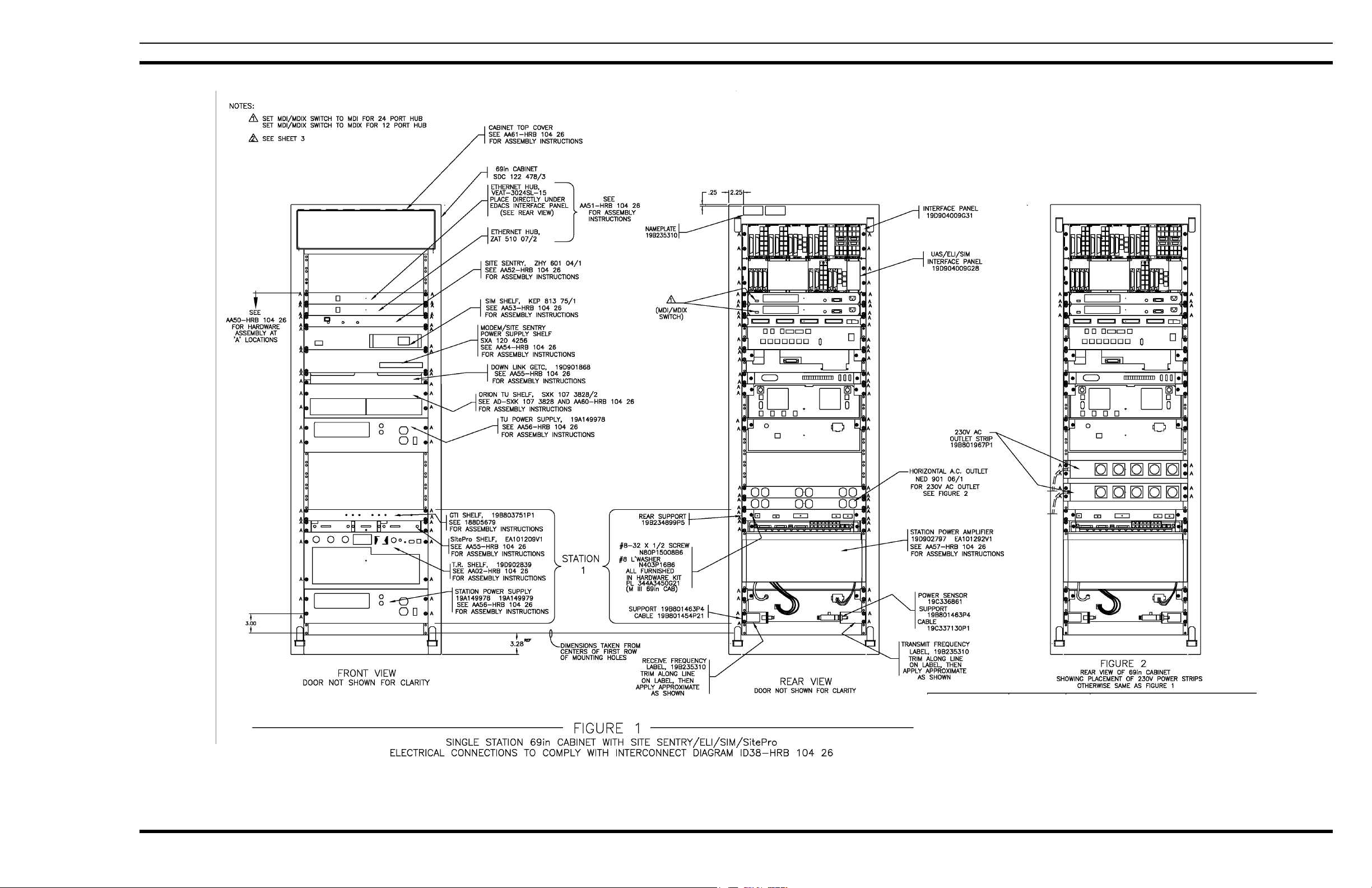
APPLICATION/ASSEMBLY DIAGRAMS
SINGLE STATION 69 IN CABINET WITH SITE PRO/SIM
AA38-HRB 104 26 Rev. B
Sheet 1 of 3
MM101418V1 R1A 5
Page 6

APPLICATION/ASSEMBLY DIAGRAMS
MULTI-STATION 83IN CABINET OR 86IN OPEN RACK WITH SITE PRO/SIM
AA38-HRB 104 26 Rev. B
Sheet 2 0f 3
6 MM101418V1 R1A
Page 7
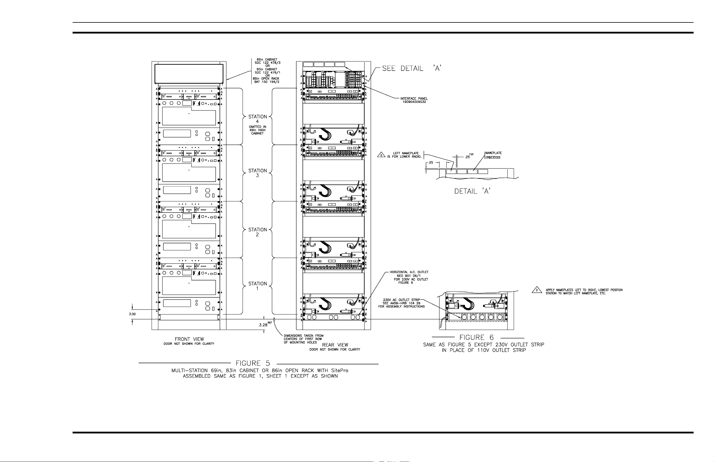
APPLICATION/ASSEMBLY DIAGRAMS
MULTI-STATION 69IN, 83IN CABINET OR 86IN OPEN RACK WITH SITE PRO ASSEMBLED
AA38-HRB 104 26 Rev. B
Sheet 3 of 3
MM101418V1 R1A 7
Page 8
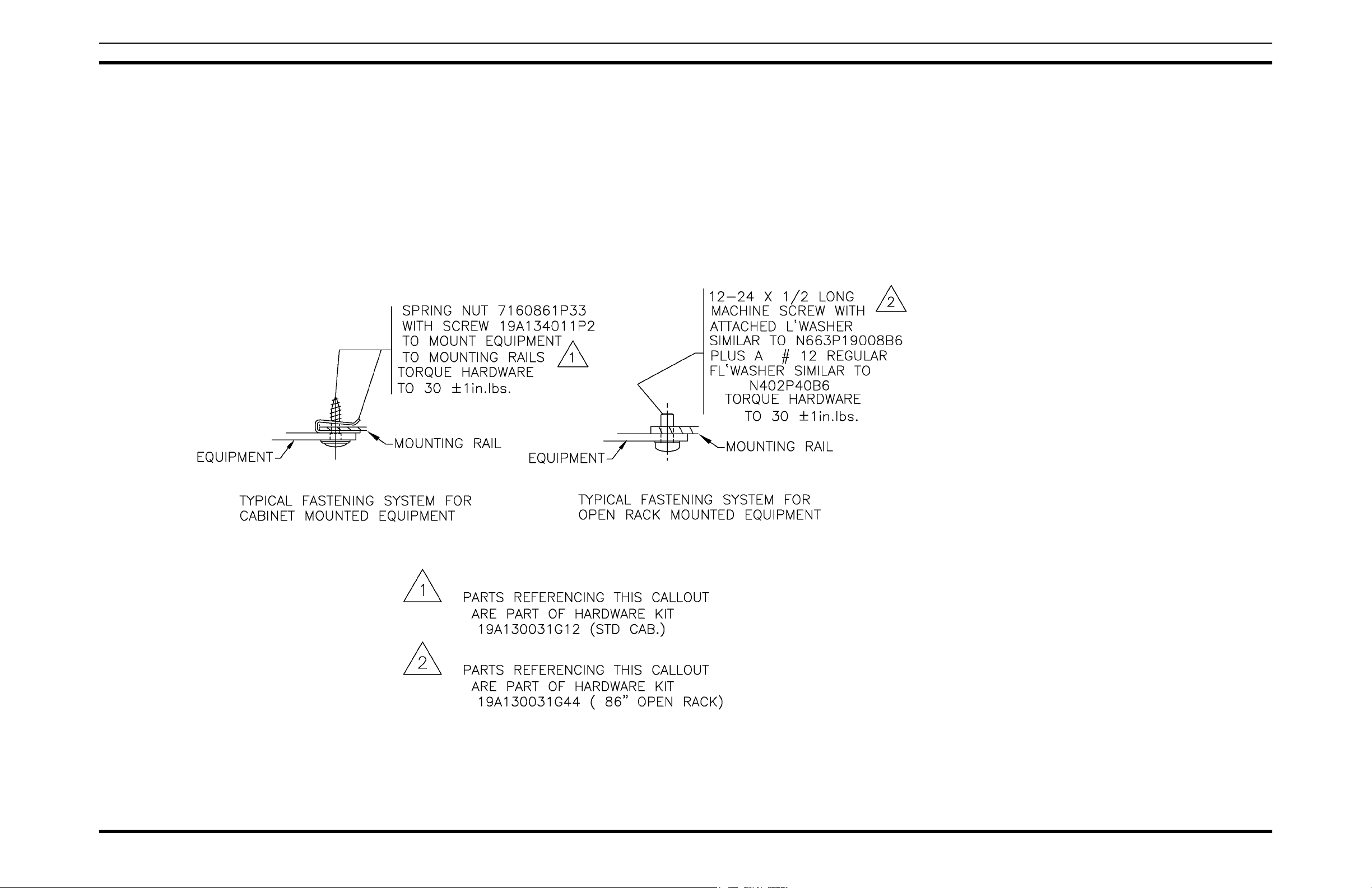
APPLICATION/ASSEMBLY DIAGRAMS
CABINET/RACK HARDWARE
AA50-HRB 104 26
8 MM101418V1 R1A
Page 9
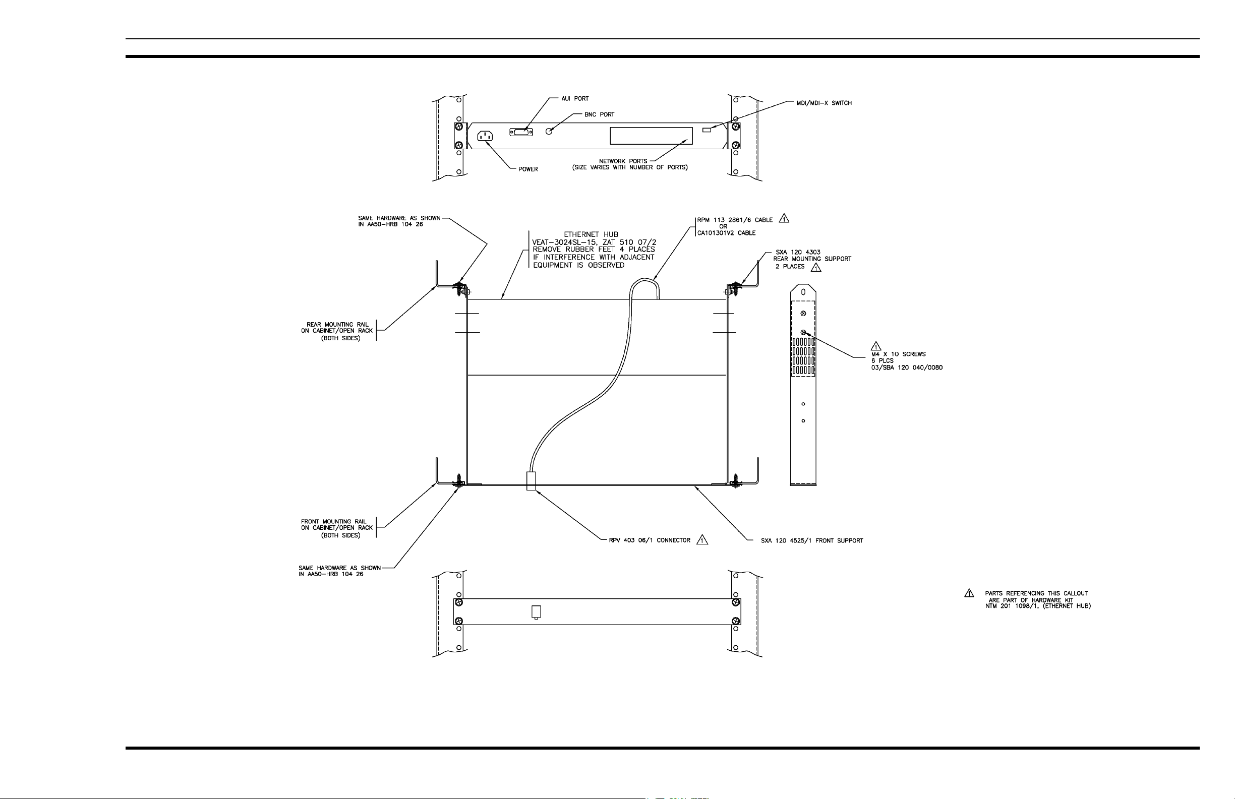
APPLICATION/ASSEMBLY DIAGRAMS
ETHERNET HUB
AA51-HRB 104 26 Rev. C
MM101418V1R1A 9
Page 10

APPLICATION/ASSEMBLY DIAGRAMS
SITE SENTRY ASSEMBLY
AA52-HRB 104 26
10 MM101418V1 R1A
Page 11

APPLICATION/ASSEMBLY DIAGRAMS
SIM SHELF
AA53-HRB 104 26
MM101418V1R1A 11
Page 12

APPLICATION/ASSEMBLY DIAGRAMS
MODEM/SITE SENTRY
POWER SUPPLY SHELF
AA54-HRB 104 26
12 MM101418V1 R1A
Page 13

APPLICATION/ASSEMBLY DIAGRAMS
GETC/SITE PRO SHELF
AA55-HRB 104 26 Rev. B
MM101418V1 R1A 13
Page 14

APPLICATION/ASSEMBLY DIAGRAMS
STATION POWER SUPPLY
AA56-HRB 104 26
14 MM101418V1 R1A
Page 15

APPLICATION/ASSEMBLY DIAGRAMS
MASTR lll Tx P.A
AA57-HRB 104 26 Rev B
Sheet 1 of 2
MM101418V1 R1A 15
.
Page 16

APPLICATION/ASSEMBLY DIAGRAMS
MASTR lll Tx P.A.
AA57-HRB 104 26 Rev. B
Sheet 2 of 2
16 MM101418V1 R1A
Page 17

APPLICATION/ASSEMBLY DIAGRAMS
R.F. CONNECTIONS DIAGRAM FOR R.F. STATIONS CABINET/RACK
ID38-HRB 104 26 Rev C
Sheet 1 of 4
MM101418V1 R1A 17
Page 18

APPLICATION/ASSEMBLY DIAGRAMS
POWER CONNECTION DIAGRAM FOR
R.F. STATIONS AND EQUIPMENT CABINET/RACK
ID 38-HRB 104 26 Rev. C
Sheet 2 of 4
18 MM101418V1 R1A
Page 19

APPLICATION/ASSEMBLY DIAGRAMS
DATA CONNECTIONS DIAGRAM
FOR R.F.STATIONS AND SIM/SITE SENTRY/SURE CALL EQUIPMENT CABINET/RACK
ID38-HRB 104 26 Rev C
Sheet 3 of 4
MM101418V1 R1A 19
Page 20

APPLICATION/ASSEMBLY DIAGRAMS
DATA CONNECTIONS DIAGRAM FOR R.F.STATIONS ONLY
CABINET/RACK
ID38-HRB 10426 Rev C
Sheet 4 of 4
20 MM101418V1 R1A
Page 21

APPLICATION/ASSEMBLY DIAGRAMS
ORION TU SHELF ASSEMBLY
AD-SXK 107 3828 Rev. E
MM101418V1 R1A 21
Page 22

APPLICATION/ASSEMBLY DIAGRAMS
MASTR III T.R. SHELF
AA02-HRB 104 26
22 MM101418V1 R1A
Page 23

APPLICATION/ASSEMBLY DIAGRAMS
CONTROL EXTENDER BOARD 188D5338G1
RF EXTENDER BOARD 188D5338G2
(188D5338, Sh. 1, Rev. 2)
MM101418V1 R1A 23
Page 24

APPLICATION/ASSEMBLY DIAGRAMS
The MASTR III 800 MHz T/R shelf is mounted in the station cabinet using Isolator Kit 350A1350G1, which provides
rubber isolators, needed at 800 MHz to dampen vibrations. This kit also provides grounding strap SXA 104 7504/1.
This grounding strap is used with the lower isolator on the right rail only. As shown above, this strap (Item 8) slips
over each end of the isolator studs with the loop oriented toward the outside cabinet wall.
GROUNDING STRAP INSTALLATION INSTRUCTIONS
(19B803970, Rev. 3)
24 MM101418V1 R1A
Page 25

APPLICATION/ASSEMBLY DIAGRAMS
CABINET GROUNDING
(19C852352, Rev. 2)
MM101418V1 R1A 25
Page 26

APPLICATION/ASSEMBLY DIAGRAMS
SITEPRO GROUNDING INSTALLATION INSTRUCTIONS
(19C852320, Rev. 1)
26 MM101418V1 R1A
Page 27

19B801454P16 & P17
(19B801454, Sh. 10, Rev. 27)
APPLICATION/ASSEMBLY DIAGRAMS
19B801454P43
(19B801454, Sh. 23, Rev. 27)
19B801454P17 & P18
(19B801454, Sh. 11, Rev. 27)
19B801454P19 & P20
(19B801454, Sh. 12, Rev. 27)
CONTROL CABLE ASSEMBLY (PART OF POWER AMPLIFIER)
19B801454P24
19B801739P1
(19B801454, Sh. 15, Rev. 27)
MM101418V1 R1A 27
Page 28

APPLICATION/ASSEMBLY DIAGRAMS
POWER CABLE (PART OF POWER AMPLIFIER)
19B801937P1
(19B801937, Sh. 1, Rev. 2)
344A3052P1
(344A3052, Sh. 1, Rev. 2)
19B235871P1
(19B237871, Sh. 1, Rev. 2)
28 MM101418V1 R1A
Page 29

PARTS LIST
MASTR E-NET
SYMBOL PART NO. DESCRIPTION
- - - - - - - - - 69" CABINET - - - - - - -
SDC 122 478/3 69-inch Cabinet.
19D417623G4 Grill, Label.
19B226318P2 Plate.
19B801476P1 Cover.
19B801476P2 Cover.
19B209539P1 Lock, rim.
19B209539P2 Lock, rim.
19B209539P3 Key, lock, rim.
344A3450G21 Hardware Kit.
5490407P29 Grommet.
19C320895G12 Fan 120 VAC.
19C320895G15 Fan 230 VAC.
- - - - - - 83" CABINET - - - - - - -
SDC 122 476/1 83-inch Cabinet.
19A130031G12 Hardware Kit.
19C337428G1 Door.
19C337428G2 Door.
19B801476P1 Cover.
19B801476P2 Cover.
19B209539P2 Lock, rim.
19B209239P2 Lock, rim.
19B209539P3 Key, lock, rim.
19B226318P2 Plate.
344A2450P21 Hardware Kit.
19C320895G12 Fan 120 VAC.
19C320895G15 Fan 230 VAC.
- - - - - - CABLES - - - - - - -
19B235871P1 Power Cable: Station Power Supply (J801) to T/R
19B801454P17 RF Cable: Low Pass Filter (J1) to Power Amplifier
19B801454P20 RF Cable: T/R Shelf (J2) to Duplexer Shelf (J2)
19B801454P19 RF Cable: T/R Shelf (J2) to Antenna Switch (J2).
19B801454P16 RF Cable: T/R Shelf (J1) to Power Amplifier (J101).
19B801454P43
Shelf (A2-P102).
(J104). Replaced by 19B801454P43.
(Used when Duplexer is installed).
RF Cable: Low Pass Filter (J1) to Power Amplifier
(J104).
PARTS LIST
*COMPONENTS ADDED, DELETED OR CHANGED BY PRODUCTION CHANGES
MM101418V1 R1A 29
Page 30

M/A-COM Wireless Systems
3315 Old Forest Road
Lynchburg, Virginia 24501
(Outside USA, 434-385-2400) Toll Free 800-528-7711
www.macom-wireless.com Printed in U.S.A.
 Loading...