


Rhein Tech Laboratories Client: M/A COM, Inc.
360 Herndon Parkway Model: M7100
Suite 1400 Standards: FCC Part 90/IC RSS-119
Herndon, VA 20170 Report Number: 2003146
http://www.rheintech.com
Date: March 8, 2004
IP
UHF-L Mobile Radio
APPENDIX I: MANUALS
Please refer to the following pages for user and installation manuals.
54 of 78

Operator’s Manual
MM102341V1
Rev. Cp1, Mar-04
M7100IP Series
Mobile Radio

MANUAL REVISION HISTORY
REVISION DATE REASON FOR CHANGE
A February 2004 Initial release.
B March 2004 Add MPE and FCC information for VHF M7100IP radio.
C March 2004 Append MPE and FCC information for UHF-L M7100IP radio.
SUPPLEMENTARY INFORMATION:
At this time, the M7100IP mobile radio may not be operated while in a desktop station in the European Community since it does not
meet immunity requirements when operated in this mode. The M7100
applications.
ACKNOWLEDGEMENTS
This device is made under license under one or more of the following US patents: 4,590,473; 4,636,791; 5,148,482; 5,185,796;
5,271,017; 5,377,229; 4,716,407; 5,502,767; 5,146,497; 5,164,986; 5,185,795.
The voice coding technology embodied in this product is protected by intellectual property rights including patent rights, copyrights,
and trade secrets of Digital Voice Systems, Inc. The user of this technology is explicitly prohibited from attempting to decompile,
reverse engineer, or disassemble the Object Code, or in any other way convert the Object Code into human-readable form.
EDACS is a registered trademark and ProGrammer, SCAT, Failsoft, ProSound, ProScan, Aegis, ProFile, ProVoice, and G-STAR are
trademarks of M/A-COM, Inc.
IMBE is a registered trademark of Digital Voice Systems, Inc.
All other brand and product names are trademarks, registered trademarks, or service marks of their respective holders.
NOTICE!
IP
mobile radio can be used in both trunked and conventional
This manual covers M/A-COM products manufactured and sold by M/A-COM, Inc.
Repairs to this equipment should be made only by an authorized service technician or facility designated by the supplier. Any repairs,
alterations or substitution of recommended parts made by the user to this equipment not approved by the manufacturer could void the
user’s authority to operate the equipment in addition to the manufacturer’s warranty.
The software contained in this device is copyrighted by M/A-COM, Inc. Unpublished rights are reserved under the copyright laws of
the United States.
This manual is published by M/A-COM, Inc., without any warranty. Improvements and changes to this manual necessitated by
typographical errors, inaccuracies of current information, or improvements to programs and/or equipment, may be made by M/A-
COM, Inc., at any time and without notice. Such changes will be incorporated into new editions of this manual. No part of this manual
may be reproduced or transmitted in any form or by any means, electronic or mechanical, including photocopying and recording, for
any purpose, without the express written permission of M/A-COM, Inc.
Copyright© 2004 M/A-COM, Inc. All rights reserved.
2

TABLE OF CONTENTS
Page
1 SAFETY SYMBOL CONVENTIONS.......................................................................................... 5
2 RF ENERGY EXPOSURE INFORMATION.............................................................................. 6
2.1 RF ENERGY EXPOSURE INFORMATION............................................................ 6
2.2 COMPLIANCE WITH RF EXPOSURE STANDARDS........................................... 6
3 OPERATION SAFETY RECOMMENDATIONS......................................................................9
3.1 TRANSMITTER HAZARDS..................................................................................... 9
3.2 SAFE DRIVING RECOMMENDATIONS ...............................................................9
4 OPERATING RULES AND REGULATIONS.......................................................................... 10
4.1 OPERATING TIPS................................................................................................... 10
5 INTRODUCTION ........................................................................................................................11
6 USER INTERFACE..................................................................................................................... 12
7 CONTROLS.................................................................................................................................. 13
7.1 POWER ON-OFF VOLUME KNOB....................................................................... 13
7.2 SYSTEM/GROUP CHANNEL KNOB.................................................................... 13
7.3 RAMP CONTROL ................................................................................................... 13
7.4 SCAN ON/OFF......................................................................................................... 13
7.5 SCAN ADD/DELETE.............................................................................................. 14
7.6 INDICATORS.......................................................................................................... 14
7.7 KEYPAD.................................................................................................................. 14
8 DISPLAY 18
8.1 RADIO STATUS ICONS......................................................................................... 18
8.2 MESSAGES.............................................................................................................. 19
9 ALERT TONES............................................................................................................................22
9.1 CALL ORIGINATE ................................................................................................. 22
9.2 AUTOKEY (TRUNKED MODE ONLY)................................................................ 22
9.3 CALL QUEUED (TRUNKED MODE ONLY).......................................................22
9.4 SYSTEM BUSY (TRUNKED MODE ONLY)........................................................ 22
9.5 CALL DENIED (TRUNKED MODE ONLY)......................................................... 22
9.6 CARRIER CONTROL TIMER................................................................................ 22
9.7 KEY PRESS ALERT................................................................................................ 22
9.8 DUAL CONTROL SWITCHING............................................................................ 22
10 OPERATION................................................................................................................................ 23
10.1 TURNING THE RADIO ON ................................................................................... 23
10.2 SELECTION MODE RULES................................................................................... 23
10.3 DIRECT ACCESS.................................................................................................... 24
10.4 MENU....................................................................................................................... 24
10.5 FEATURE ENCRYPTION DISPLAY..................................................................... 28
10.6 SYSTEM/GROUP/CHANNEL SELECTION .........................................................29
11 TRUNKED MODE OPERATION.............................................................................................. 31
11.1 RECEIVING A CALL..............................................................................................31
11.2 SENDING A CALL.................................................................................................. 31
3

TABLE OF CONTENTS
Page
11.3 CONVENTIONAL FAILSOFT................................................................................31
11.4 EMERGENCY OPERATION ..................................................................................32
11.5 SYSTEM SCAN OPERATION................................................................................32
11.6 GROUP SCAN OPERATION..................................................................................34
11.7 INDIVIDUAL CALLS .............................................................................................36
11.8 SCAT OPERATION.................................................................................................37
11.9 TELEPHONE INTERCONNECT CALLS...............................................................38
11.10 MOBILE DATA .......................................................................................................39
11.11 STATUS/MESSAGE OPERATION.........................................................................42
11.12 EDACS CONVENTIONAL P1 SCAN ....................................................................43
11.13 DYNAMIC REGROUP OPERATION.....................................................................43
12 CONVENTIONAL MODE OPERATION.................................................................................44
12.1 RECEIVING A CALL..............................................................................................44
12.2 SENDING A CALL..................................................................................................44
12.3 EMERGENCY OPERATION ..................................................................................44
12.4 SCANNING CONVENTIONAL CHANNELS........................................................45
12.5 TURNING SCAN ON ..............................................................................................46
12.6 TURNING SCAN OFF.............................................................................................47
12.7 SQUELCH ADJUST.................................................................................................47
12.8 TYPE 99 DECODE (CONVENTIONAL ONLY)....................................................48
12.9 DIRECT MODE OPERATION (CONVENTIONAL ONLY).................................49
13 PROJECT 25 (P25) CONVENTIONAL OPERATION............................................................50
13.1 GROUP CALLS IN P25 MODE...............................................................................50
13.2 INDIVIDUAL CALLS IN P25 MODE ....................................................................50
13.3 EMERGENCY GROUP CALLS IN P25 MODE.....................................................51
14 TRUNKED OR CONVENTIONAL MODE OPERATION .....................................................52
14.1 SIREN/LIGHT OPERATION...................................................................................52
14.2 DIGITAL VOICE OPERATION..............................................................................52
14.3 DUAL CONTROL OPERATION ............................................................................57
14.4 MULTIPLE RADIO OPERATION..........................................................................58
14.5 MACRO KEY OPERATION ...................................................................................59
14.6 INTERCONNECT CALL (SYSTEM MODEL ONLY) ..........................................60
14.7 KEYPAD REMAPPING...........................................................................................60
GLOSSARY .........................................................................................................................................62
RADIO SETUP....................................................................................................................................64
WARRANTY .......................................................................................................................................66
4
1 SAFETY SYMBOL CONVENTIONS
The following conventions are used throughout this manual to alert the user to general safety precautions
that must be observed during all phases of operation, service, and repair of this product. Failure to comply
with these precautions or with specific warnings elsewhere in this manual violates safety standards of
design, manufacture, and intended use of the product. M/A-COM, Inc. assumes no liability for the
customer’s failure to comply with these standards.
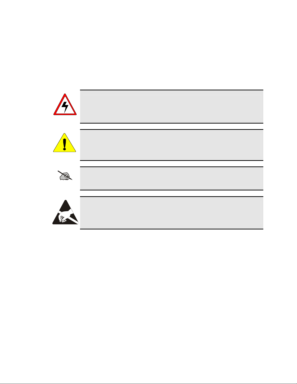
The WARNING symbol calls attention to a procedure, practice, or the like, which, if not
correctly performed or adhered to, could result in personal injury. Do not proceed beyond
WARNING
CAUTION
NOTE
a WARNING symbol until the conditions identified are fully understood or met.
The CAUTION symbol calls attention to an operating procedure, practice, or the like,
which, if not performed correctly or adhered to, could result in damage to the equipment or
severely degrade the equipment performance.
The NOTE symbol calls attention to supplemental information, which may improve
system performance or clarify a process or procedure.
The ESD symbol calls attention to procedures, practices, or the like, which could expose
equipment to the effects of Electro-Static Discharge. Proper precautions must be taken to
prevent ESD when handling circuit modules.
5

2 RF ENERGY EXPOSURE INFORMATION
2.1 RF ENERGY EXPOSURE AWARENESS, CONTROL
INFORMATION, AND OPERATION INSTRUCTIONS FOR
FCC OCCUPATIONAL USE REQUIREMENTS
Before using your mobile two-way radio, read this important RF energy awareness and control
information and operational instructions to ensure compliance with the FCC’s RF exposure
guidelines.
This radio is intended for use in occupational/controlled conditions, where users have full
knowledge of their exposure and can exercise control over their exposure to meet FCC
NOTE
This two-way radio uses electromagnetic energy in the radio frequency (RF) spectrum to provide
communications between two or more users over a distance. It uses RF energy or radio waves to send and
receive calls. RF energy is one form of electromagnetic energy. Other forms include, but are not limited
to, electric power, sunlight, and x-rays. RF energy, however, should not be confused with these other
forms of electromagnetic energy, which, when used improperly, can cause biological damage. Very high
levels of x-rays, for example, can damage tissues and genetic material.
limits. This radio device is NOT authorized for general population, consumer, or any other
use.
Experts in science, engineering, medicine, health, and industry work with organizations to develop
standards for exposure to RF energy. These standards provide recommended levels of RF exposure for
both workers and the general public. These recommended RF exposure levels include substantial margins
of protection. All two-way radios marketed in North America are designed, manufactured, and tested to
ensure they meet government established RF exposure levels. In addition, manufacturers also recommend
specific operating instructions to users of two-way radios. These instructions are important because they
inform users about RF energy exposure and provide simple procedures on how to control it. Please refer to
the following websites for more information on what RF energy exposure is and how to control your
exposure to assure compliance with established RF exposure limits.
http://www.fcc.gov/oet/rfsafety/rf-faqs.html
http://www.osha.gov./SLTC/radiofrequencyradiation/index.html
2.1.1 Federal Communications Commission Regulations
Your M/A-COM, Inc. M7100IP mobile two-way radio is designed and tested to comply with the
FCC RF energy exposure limits for mobile two-way radios before it can be marketed in the United
States. When two-way radios are used as a consequence of employment, the FCC requires users
to be fully aware of and able to control their exposure to meet occupational requirements.
Exposure awareness can be facilitated by the use of a label directing users to specific user
awareness information. Your M/A-COM, Inc. M7100
product label. Also, your M7100
operating instructions required to control your RF exposure and to satisfy compliance
requirements.
IP
Installation and Operator’s Manuals include information and
IP
two-way radio has an RF exposure
2.2 COMPLIANCE WITH RF EXPOSURE STANDARDS
Your M/A-COM, Inc. M7100IP mobile two-way radio is designed and tested to comply with a number of
6
national and international standards and guidelines (listed below) regarding human exposure to RF
electromagnetic energy. This radio complies with the IEEE and ICNIRP exposure limits for
occupational/controlled RF exposure environment at duty factors of up to 50% talk-50% listen and is
authorized by the FCC for occupational use. In terms of measuring RF energy for compliance with the
FCC exposure guidelines, your radio antenna radiates measurable RF energy only while it is transmitting
(talking), not when it is receiving (listening) or in standby mode.
IP
Your M/A-COM, Inc. M7100
mobile two-way radio complies with the following RF energy exposure
standards and guidelines:
• United States Federal Communications Commission (FCC), Code of Federal Regulations; 47 CFR
§§ 2 sub-part J.
• American National Standards Institute (ANSI)/Institute of Electrical and Electronic Engineers
(IEEE) C95.1-1992.
• Institute of Electrical and Electronic Engineers (IEEE) C95.1-1999.
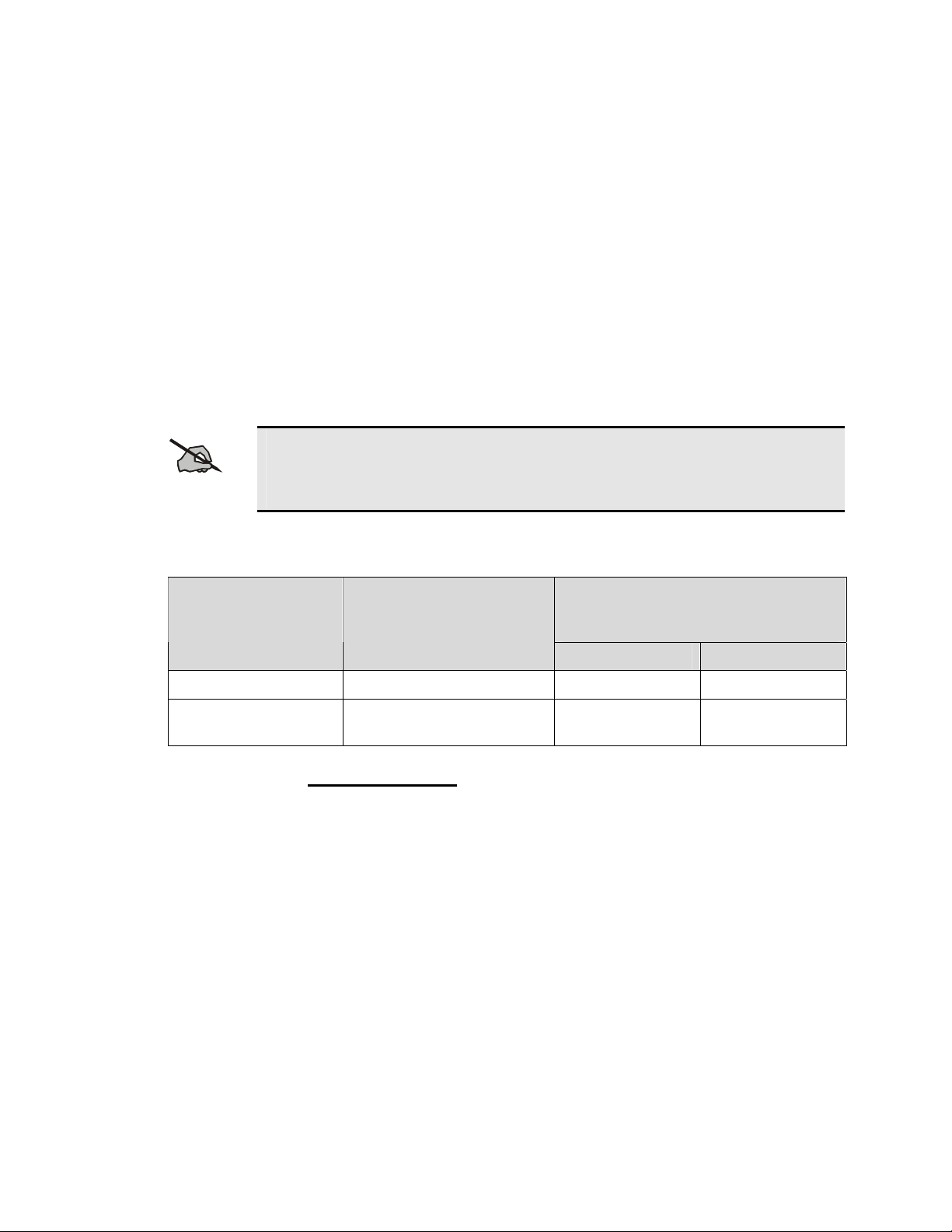
Table 2-1 lists the recommended minimum lateral distance for bystanders in an
uncontrolled and controlled environment, from transmitting types of antennas (i.e.,
NOTE
monopoles over a ground plane, or dipoles) at rated radio power for mobile radios installed
in a vehicle.
Table 2-1: Rated Power and Recommended Minimum Lateral Distance
MOBILE RADIO
FREQUENCY SPLIT
RATED POWER OF
VEHICLE-INSTALLED
MOBILE TWO-WAY
RADIO
RECOMMENDED MINIMUM
LATERAL DISTANCE FROM
TRANSMITTING ANTENNA
Controlled Uncontrolled
VHF 110 Watts 92.87 cm 207.67 cm
UHF–L
(Antenna P/N: AN102800V1)
50 Watts
50.89 cm 113.79 cm
2.2.1 Mobile Antennas
Install the radio’s antenna (M/A-COM part number 19B209568P6 for VHF radios and
AN102800V1 for UHF-L radios) in the center of the vehicle’s roof. These mobile antenna
installation guidelines are limited to metal body motor vehicles or vehicles with appropriate
ground planes. The antenna installation should additionally be in accordance with the following.
1. The requirements of the antenna manufacturer/supplier included with the antenna.
IP
2. Instructions in the M7100
lengths.
3. The installation manual providing specific information of how to install the antennas to
facilitate recommended operating distances to all potentially exposed persons.
Use only the M/A-COM approved/supplied antenna(s) or approved replacement antenna.
Unauthorized antennas, modifications, or attachments could damage the radio and may violate
FCC regulations.
Radio Installation Manual, including minimum antenna cable
7

2.2.2 Approved Accessories
This radio has been tested and meets the FCC RF exposure guidelines when used with the M/ACOM accessories supplied or designated for use with this product. Use of other accessories may
not ensure compliance with the FCC’s RF exposure guidelines, and may violate FCC regulations.
For a list of M/A-COM approved accessories refer to the product manuals, M/A-COM’s Products
and Services Catalog, or contact M/A-COM at 1-800-368-3277.
2.2.3 Contact Information
For additional information on exposure requirements or other information, contact M/A-COM,
Inc. at 1-800-528-7711 or at http://www.macom-wireless.com
.
8

3 OPERATION SAFETY RECOMMENDATIONS
3.1 TRANSMITTER HAZARDS
The operator of any mobile radio should be aware of certain hazards common to the
operation of vehicular radio transmitters. A list of several possible hazards is given:
WARNING
• Explosive Atmospheres – Just as it is dangerous to fuel a vehicle with the motor running, similar
• Interference to Vehicular Electronics Systems – Electronic fuel injection systems, electronic anti-
• Electric Blasting Caps – To prevent accidental detonation of electric blasting caps, DO NOT use
hazards exist when operating a mobile radio. Be sure to turn the radio off while fueling a vehicle. Do
not carry containers of fuel in the trunk of a vehicle if the radio is mounted in the trunk.
Areas with potentially explosive atmosphere are often, but not always, clearly marked. Turn OFF your
radio when in any area with a potentially explosive atmosphere. It is rare, but not impossible that the
radio or its accessories could generate sparks.
skid braking systems, electronic cruise control systems, etc., are typical electronic systems that can
malfunction due to the lack of protection from radio frequency energy present wh en transmitting. If
the vehicle contains such equipment, consult the dealer and enlist their aid in determining the expected
performance of electronic circuits when the radio is transmitting.
two-way radios within 1000 feet of blasting operations. Always obey the “Turn Off Two-Way
Radios” signs posted where electric blasting caps are being used. (OSHA Standard: 1926-900)
• Liquefied Petroleum (LP) Gas Powered Vehicles – Mobile radio installations in vehicles powered
by liquefied petroleum gas with the LP gas container in the trunk or other sealed-off space within the
interior of the vehicle must conform to the National Fire Protection Association standard NFPA 58
requiring:
The LP gas container an d its fittings.
Outside filling connections shall be used for the LP gas container.
The LP gas container shall be vented to the outside of the vehicle.
3.2 SAFE DRIVING RECOMMENDATIONS
(Recommended by AAA)
• Read the literature on the safe op eration of the radio.
• Keep both hands on the steering wheel and the microphone in its hanger whenever the vehicle is in
motion.
• Place calls only when the vehicle is stopped.
• When talking from a moving vehicle is unavoidable, drive in the slower lane. Keep conversations
brief.
• If a conversation requires taking notes or complex thought, stop the vehicle in a safe place and
continue the call.
• Whenever using a mobile radio, exercise caution.
9

4 OPERATING RULES AND REGULATIONS
Two-way FM radio systems must be operated in accordance with the rules and regulations of the local,
regional, or national government.
IP
In the United States, the M7100
regulations of the Federal Communications Commission (FCC). As an operator of two-way radio
equipment, you must be thoroughly familiar with the rules that apply to your particular type of radio
operation. Following these rules helps eliminate confusion , assures the most efficient use of the existing
radio channels, and results in a smoothly functioning radio network.
When using your two-way radio, remember these rules:
• It is a violation of FCC rules to interrupt any distress or emergency message. As your radio operates
in much the same way as a telephone “party line,” always listen to make sure that the channel is clear
before transmitting. Emergency calls have priority over all other messages. If someone is sending an
emergency message – such as reporting a fire or asking for help in an accident – KEEP OFF THE
AIR!
• The use of profane or obscene language is prohibited by Federal law.
• It is against the law to send false call letters or false distress or emergency messages. The FCC
requires that you keep conversations brief and confine them to business. To save time, use coded
messages whenever possible.
Series mobile radio must be operated in accordance with the rules and
• Using your radio to send personal messages (except in an emergency) is a violation of FCC rules. You
may send only those messages that are essential for the operation of your business.
• It is against Federal law to repeat or otherwise make known anything you overhear on your radio.
Conversations between others sharing your channel must be regarded as confidential.
• The FCC requires that you identify yourself at certain specific times by means of your call letters.
Refer to the rules that apply to your particular type of operation for the proper procedure.
• No changes or adjustments shall be made to the equipment except by an authorized or certified
electronics technician.
Under U.S. law, operation of an unlicensed radio transmitter within the jurisdiction of the
United States may be punishable by a fine of up to $10,000, imprisonment for up to two
NOTE
(2) years, or both.
4.1 OPERATING TIPS
The following conditions tend to reduce the effective range of two-way radios and should be avoided
whenever possible:
• Operating the radio in areas of low terrain, or while under power lines or bridges.
• Obstructions such as mountains and buildings.
• In areas where transmission or reception is poor, some improvement can be obtained by moving a few
yards in another direction or moving to a higher elevation.
10

5 INTRODUCTION
This manual describes how to use the M7100IP Series Mobile Radio. The M7100IP is a synthesized,
microprocessor-based, high performance mobile FM radio providing reliable two-way communications in
both the Enhanced Digital Access Communications System (EDACS
conventional communication systems.
In the EDACS or trunked system mode, the user selects a communications system and group. In this mode,
channel selection is transparent to the user and is con trolled via digital communication with the system
controller. This provides advanced programmable features and fast access to communication channels.
In the conventional mode, the user selects a channel and directly communicates on that channel. In this
mode, a system refers to a set of channels. A channel is a transmit/receive radio frequency pair.
The exact operation of the radio will depend on the operating mode, the radio's programming and the
particular radio system. Most features described in this manual can be enabled or disabled through
programming. Consult the system administrator for the particular features that are programmed into the
IP
M7100
.
®
) trunking environment and
11
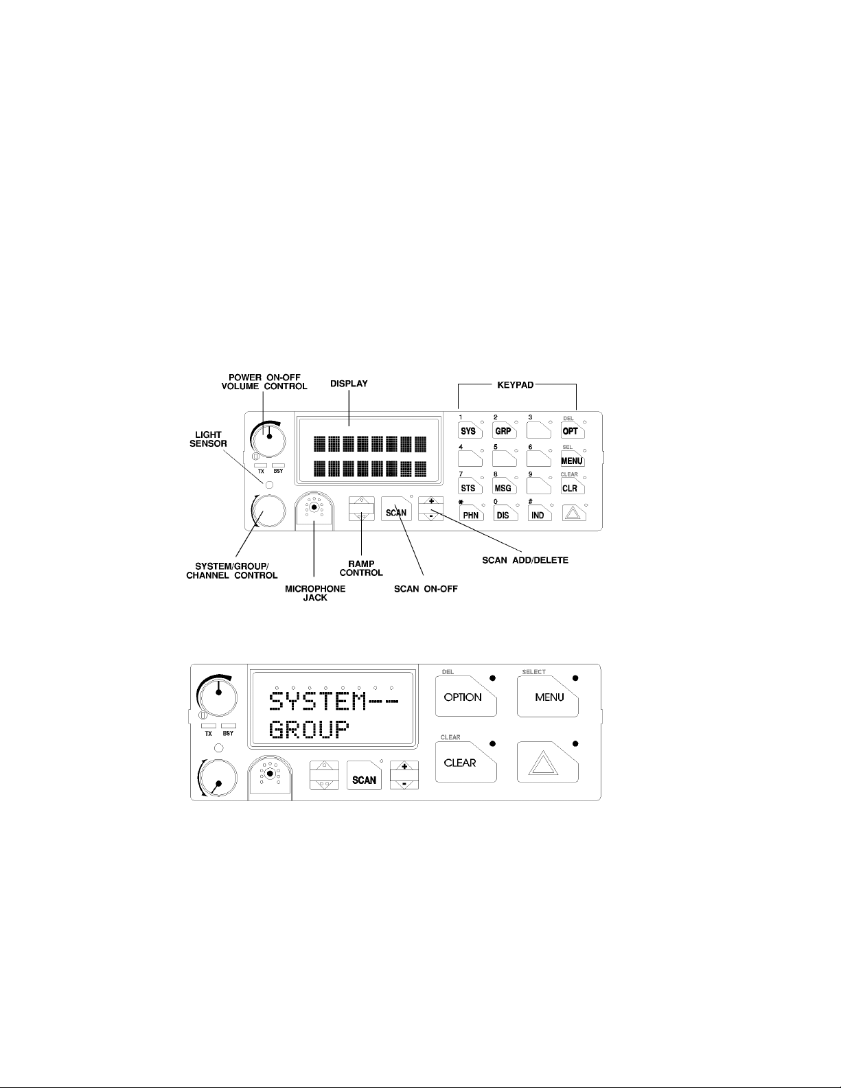
6 USER INTERFACE
The M7100IP operating controls are located on the radio's front panel (see Figure 6-1and Figure 6-2). A
keypad, vacuum florescent display for radio status information and a microphone jack are on the front
panel. The front panel also provides a rotary SYSTEM/GROUP/CHANNEL knob, POWER ON-
OFF/VOLUME control, a ramp up/ramp down control, Scan add/delete control, and a SCAN ON-OFF
control for scan operation.
The keypad is used for manual number entry for individual calls, access to a telephone interconnect system
and activation of various EDACS or conventional features such as menu selection. Each key has an
associated LED for status indication.
The display has two lines with eight alphanumeric-characters used to show the operational mode of the
radio. There is one LED for indicating transmitter ON and one LED to indicate CHANNEL BUSY located
below the POWER ON-OFF/VOLUME Control.
IP
Figure 6-1: M7100
Figure 6-2: M7100
Series Mobile Radio System Model Front Panel
IP
Series Mobile Radio Scan Model Front Panel
12

7 CONTROLS
f
This section describes the buttons, keys and rotary knobs used to control the M7100IP Series Mobile Scan
and System Model radios. All functions and controls of the Scan radio operate the same as the
corresponding functions and controls on the System radio. The Scan radio is equipped with a 4-button
keypad and the System radio is equipped with a 16-button keypad.
Many of the control buttons and keys have or can be programmed to have a primary function and a
secondary function. The SCAN button can be programmed (as a secondary function) to toggle the keypad
keys between their primary function and their secondary function.
7.1 POWER ON-OFF VOLUME KNOB
This rotary knob applies power to the radio and adjusts the receiver volume. Rotating the
control clockwise out of detent applies power to the radio. A single alert tone sounds (i
enabled through programming) to indicate the radio is operational.
Rotating the control clockwise increases the volume level. Minimum volume levels can be programmed
into the radio to prevent missed calls due to a lo w volume setting. While adj usting the volu me, the display
will briefly indicate the volume level (i.e. VOL = 3 1). The volume range is from a minimum level of zero
(displayed as OFF in the display) up to 31, which is the loudest level.
7.2 SYSTEM/GROUP CHANNEL KNOB
This rotary switch selects the systems or groups/channels, depending upon programming.
This 16-position rotary switch has no stop or detent. See SYSTEM/GROUP/CHANNEL
SELECTION section for more details.
7.3 RAMP CONTROL
The primary function of this rocker type button is to scroll through the System list or the
Group/Channel list depending upon programming. The secondary function is to increment or
decrement items within a list (phone list for example). Press
and press
. to scroll in decreasing order. To auto-ramp, press and hold the button.
, to scroll in increasing order
7.4 SCAN ON/OFF
The primary function of this button is to toggle scan operation ON and OFF. When the radio
is scanning, the SCAN LED is on and all groups or channels in the scan list of the currently
selected systems are scanned.
The secondary function of the SCAN button is to toggle the keypad buttons between their primary function
and their secondary function.
13

f
7.5 SCAN ADD/DELETE
This rocker type button is used to display the current SCAN status for a
group/channel and then either add or delete the group/channel from the system scan
list.
7.6 INDICATORS
Transmitter enabled - ON when the radio is transmitting.
BuSY - On indicates a carrier is being received (the channel is busy). Note that i
the selected channel is programmed for Channel Guard (CG), Digital Channel Guard
(DCG) or Type 99 (T99) tone decode op eration, the radio will not un-squelch if a
valid tone or code is not received; the BSY indicator will be on.
IP
Figure 7-1: M7100
System Model Keypad
IP
Figure 7-2: M7100
Scan Model Keypad
7.7 KEYPAD
The keypad is similar to a telephone keypad but with four (4) additional buttons on the side for a total of 16
keys. In addition to numbers (1-9, *, 0 and #), which is a secondary function, most of the keys have or can
be programmed to have a primary function. A symbol or abbreviated word describing its primary function
is labeled on the keycap. Each labeled keycap is associated with a radio feature (or primary function). The
radio must be programmed to operate with the Standard or the Optional keycap configuration.
14
A keylight (LED) is associated with each key or button. This can light when the associated function is
active. In some conditions, the keylight can blink to indicate an action status.
The keypad key functions can be remapped to any of the primary function keys using the PC programming
software. It is suggested that the blank keypad (located at the back of this manual) be completed if the
keypad key functions are changed.
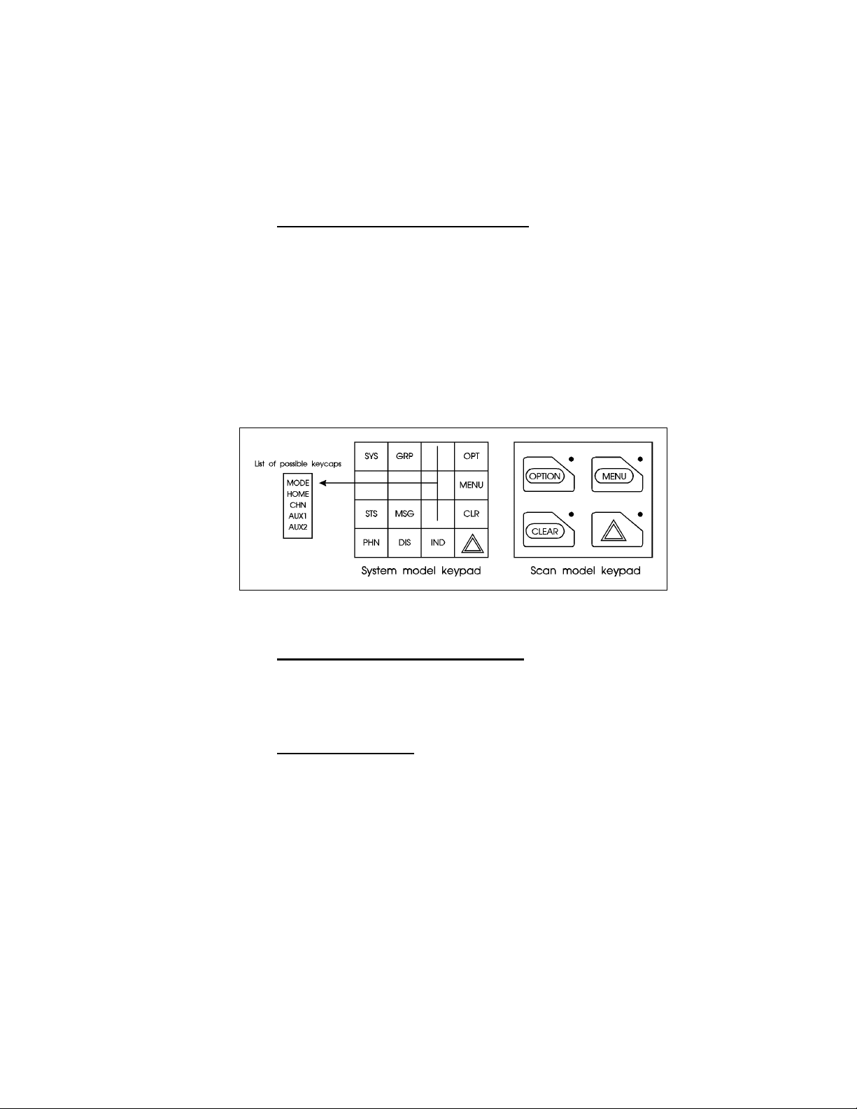
7.7.1 Standard Keycap Configuration
The Standard keycap package for the System radio includes five (5) labeled keycaps (MODE,
HOME, CHN, AUX1 and AUX2) and six (6) blank keycaps, which can be placed on any of the
five key locations (numbers 3-6 and 9) shown in Figure 7-3. The keycap represents the primary
function programmed for that key location. See Secion 7.7.3 for a description of the primary
function associated with these five (5) keycaps.
The standard keycap package for the Scan radio includes five (5) labeled keycaps [MENU,
CLEAR, SELECT, EMERGENCY
which can be placed on any of the four (4) keypad keys. The keycap represents the primary
function programmed for that key location.
E or “E,” and OPTION] and five (5) blank keycaps,
IP
Figure 7-3: Standard M7100
Keycaps Configuration
7.7.2 Optional Keycap Configuration
The optional keycap package for the System radio includes sixty (60) additional keycaps (shown
in Section 7.7.3), which can be placed on any key location desired. Keep in mind, the keycap
represents the primary function programmed for that key location.
7.7.3 Key Descriptions
MODE This key is used to enter the Conventional System selection mode.
HOME This key returns the radio to the Home System/Group where it is programmed.
CHN This key is used to enter the Channel select mode.
AUX1 & 2
S This key is used to enter the System select mode.
g This key is used to enter the Group select mode.
o
or
O
These keys are used to control output 1 or 2. Their definition is PC programmable.
The “OPT” or “OPTION” key is used to toggle a PC programmable feature ON
and OFF.
15

DEL Secondary function - used to delete a digit during numeric entry (see Section
10.2).
M Primary function - accesses the menu list. This is a list of additional features that
are not available directly from the keypad. See Section 10.4 for details.
SELECT Secondary function - activates a selected item within a list. After the menus list is
accessed, select a menu item from the list via RAMP controls,
, or ., and
activate it with this key. Once activated, MENU continues its secondary function
for activating a selected parameter setting until the radio returns to its normal
receive state. This is similar to an enter key.
s The Status key permits the transmission of a pre-programmed status message to
an EDACS site.
n The Message key permits the transmission of a pre-programmed message to an
EDACS site.
c
Serves several purposes depending on the operating mode. In trunked mode, the
CLR button exits the current operation and removes all displays associated with it.
The radio and display then return to the group receive state. In Conventional
mode, pressing this button unmutes the receiver so activity on the selected channel
C
can be monitored. When pressed and held for approximately 3 seconds, this button
toggles conventional channel decoding (Channel Guard, Digital Channel Guard,
T99) ON and OFF if programmed for the selected channel.
p Used to place telephone calls through the radio by selecting the interconnect
special call function. See TELEPHONE INTERCONNECT CALLS for
details.
d Used to adjust the current display intensity and the keypad backlight level.
i Used to call an individual or make an all-call by selecting the individual call
function. See INDIVIDUAL CALLS for details.
E
The Emergency key is used to declare emergencies.
or
ALM This key toggles the external alarm ON/OFF. The external alarm is used to
indicate the radio is receiving an Individual Call. Press the key once to enable
external alarm and press again to disable external alarm.
SG1-SG5 This key corresponds to five (5) pre-programmed System/Groups. Pressing a key
programmed for SG1 would switch the radio to the pre-programmed
System/Group 1. Pressing a key programmed for SG2 would switch the radio to
the pre-programmed System/Group 2, etc.
WAIL, YLP,
RST, SL1SL8
The WAIL and YLP (Yelp) keys are designed to control an optional Siren
package. The SL1-SL8 (Siren/Light) keys are designed to control an optional
Siren/Light package. The RST (Reset) key is used to turn all sirens and lights
OFF.
16
SPK This key function is used to toggle the external speaker ON/OFF.

STO-ST9 The status 0-9 keys are used to send a pre-programmed status message to the
EDACS site.
PVT The PVT key enables or disables Private Mode for the System/Group displayed.
See the Private Operation section.
KEY Displays the Encrypted Keys. This selects the DISP KEY operation from the
menu functions.
G* This key function is used in Conventional Mode to send G-STAR emergency
signaling.
PA This key function enables and disables the Public Address feature.
# DTMF keypad function.
1 thru 9 Keypad numbers.
* DTMF Keypad function.
7.7.4 Primary Functions (Quick Access)
The secondary function of the k button is to toggle the keypad buttons between their primary
function and their secondary function. When the secondary keypad is active, i.e. entering phone
digits for an interconnect call, the k button can be used to toggle the keypad buttons back to
their primary function, perform a task (siren/light enable), and then toggle back to finish entering
the digits for the phone number. PRIMARY is displayed when the k button is used to
toggle the keypad keys back to their primary functions. This provides quick access to the primary
functions of the keypad. This is a programmable feature of the k button only. Careful
consideration should be given to possible operational conflicts before enabling this feature.
Several keys on the Scan version have a secondary function. The m key is the SELECT
secondary function with the C key remaining the same for the secondary function. On the
System version, the o has a secondary function for DELETE, m is SELECT, and c
retains its CLEAR function.
17
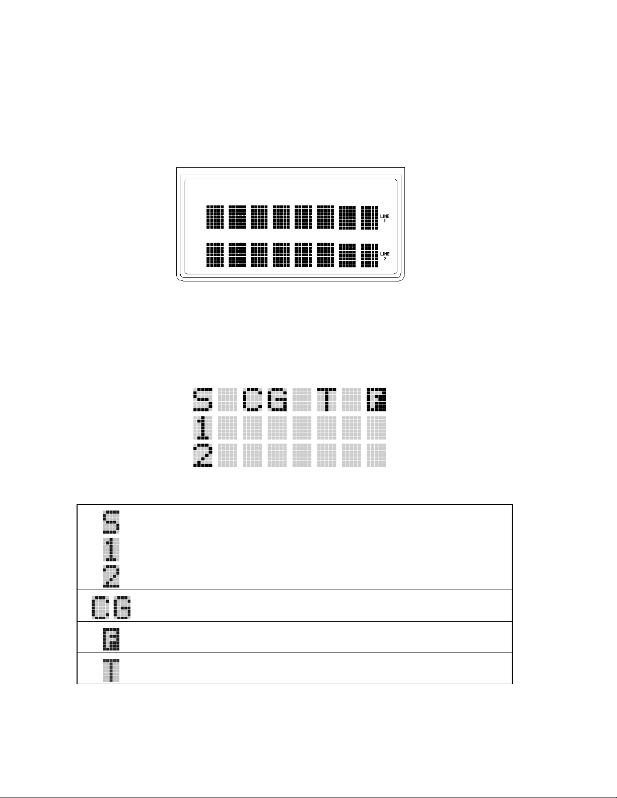
8 DISPLAY
The radio's display is shown in Figure 8-1. The two character lines are used to display system, group and
channel names and also operational messages. Each line contains eight alphanumeric character blocks. See
Figure 6-2 for a typical display.
IP
Figure 8-1: M7100
8.1 RADIO STATUS ICONS
Series Mobile Radio Display
Status icons are indicators that show the various operating characteristics of the radio. The icons appear on
the first line of the display.
• indicates selected group or channel is in scan list.
• indicates selected group or channel is programmed as Priority 1 in scan list.
• indicates selected group or channel is programmed as Priority 2 in scan list.
• indicates conventional channel enabled with Channel Guard function.
• indicates the EDACS system is in Failsoft™ mode (if enabled through
programming).
18
• indicates Type 99 Decode is enabled on a conventional channel.

8.2 MESSAGES
During radio operation, various messages are displayed on either line 1 or line 2. Typical messages include
control channel status information, such as system busy or call denied, or messages associated with the
radio's operation, (i.e. volume adjust). These messages are described as follows:
Table 8-1: Display Messages
MESSAGE NAME DESCRIPTION
QUEUED
SYS BUSY
DENIED
CC SCAN
WA SCAN
TALKARND
*RXEMER*
*TXEMER*
VOL=31
UNKNOWN
TX DATA
RX DATA
DATA OFF
DATA ON
SYSC ON
SYSC OFF
T99 ON
T99 OFF
PA ON
PA OFF
ALRM ON
ALRM OFF
PVT DIS
FRCD PVT
Call Queued Trunked mode only. Indicates the system has placed the call in a request queue.
System Busy Trunked mode only. Indicates the system is busy, no channels are currently
Call Denied Trunked mode only. Indicates the radio is not authorized to operate on the selected
Control Channel Scan Trunked mode only. Indicates the control channel is lost and the radio has entered
Wide Area Scan Trunked mode only. Indicates the control channel is lost and the radio has entered
Talk-around Conventional mode only. Indicates the radio is operating on conventional channels
Receive Emergency Trunked mode only. Indicates an emergency call is being received. This message
Transmit Emergency Trunked mode only. Indicates an emergency call has been transmitted. This
Volume Level Indicates the current volume level. The volume level display ranges from OFF
Caller's ID Not
Received
Transmit Data Trunked mode only. Indicates the radio is transmitting a data call.
Receive Data Trunked mode only. Indicates the radio is receiving a data call. Displayed on line 2.
Data OFF Trunked mode only. Indicates the radio is in the data disabled state. Displayed on
Data ON Trunked mode only. Indicates the radio has been toggled to the data enable state.
System Scan Features
ON
System Scan Features
OFF
Type 99 Decode ON Conventional mode only. Indicates the Type 99 Decode feature is enabled.
Type 99 Decode OFF Conventional mode only. Indicates the Type 99 Decode feature is disabled.
Public Address ON Indicates that the public address function of the radio is enabled.
Public Address OFF Momentary (2 seconds) indicates that public address function of the radio was
External Alarm Enabled Indicates that the external alarm function of the radio is enabled.
External Alarm
Disabled
Private Mode Disabled Indicates that private mode is disabled or no encryption key has been programmed
Forced Private
Operation
available, the queue is full or an individual call is being attempted to a radio that is
currently transmitting.
system.
the Control Channel Scan mode to search for the control channel.
the Wide Area Scan mode to search for a new system (if enabled through
programming).
in talk-around mode (no repeater).
will be flashing on line 2.
message will be flashing on line 2.
(silent) to 31 (loudest).
Indicates that an individual call is being received, but the caller's ID was not
received.
line 1.
Displayed for two seconds on line 1 when toggled to enable state.
Trunked mode only. Indicates the System Scan features are enabled.
Trunked mode only. Indicates the System Scan features are disabled.
disabled.
Momentary (2 seconds) indicates that the external alarm function of the radio was
disabled.
for the selected group/channel or special call.
Indicates that forced private operation has been pre-programmed into r a dio.
19

MESSAGE NAME DESCRIPTION
NO KEY #
BCKL=1-6
GR
ID
WHC=1
PHONE
CONV FS
MENU
SYS=1-64
GRP=1-64
INDV=1-99
PHN=1-99
SEL PHN
SEL INDV
SYS ALL
Ggg-v.vv
*PHONE*
DUAL
NO ENTRY
INV SYS
CHN=1-99
FIX LIST
FIXED P1
Encryption Key Missing Flashing indicator indicates that no encryption key or an incorrect encryption key is
Backlight Indicates the display intensity and keypad backlight level.
Group ID Indicates that the call is a group call and is followed by the GID of the caller
Individual ID Indicates the call is an individual call and the ID number of the caller, example "ID
Who Has Called This display indicates the number from the Who Has Called list. Individual calls
Phone Call Displayed when a phone call is received from the site. It is displayed in line 1 of the
Conventional Failsoft Displayed when a failure of the EDACS system occurs. All communication will be
Displayed when the menu key is pressed and remains displayed in line 1 until a
System = 1 - 64 The system number for the current base station of the system displayed in line 1. It
Group = 1 - 64 The group number of the group displayed in line 2 of display. It is displayed in line
Individual = 1 - 99 Indicates which item in the individual call list is being displayed. It is displayed in
Phone = 1 - 99 Indicates which item in the phone list is being displayed. It is displayed in line 2 of
Select Phone After pressing the PHN key, selecting an entry from the phone list by typing the
Select Individual ID Displayed on line 1 when an entry from the individual ID list is selected after
System All Call Displayed on line 1 to indicate a system all-call has been received (trunked mode
Code Group and
Revision Number
Phone Call Displayed when an initiated phone call is in progress. This is displayed on line 2 of
Dual Control Operation Displayed on an idle control unit when configured as dual control opera tion.
Indicates that there is no data stored in one of the programmable items in either the
Invalid System Displayed when the current system is an invalid type.
Channel = 1 - 99 Displayed on line 1 of the display. This is a conventional channel index displayed
Fixed List The Priority scan list is fixed and cannot be changed using the add or delete keys.
Fixed Priority 1 The Priority 1 scan channel is fixed and cannot be changed using the add or delete
programmed into the radio.
(trunked mode only).
2725" (trunked mode only).
received but not responded to are stored in a Who Has Called list. This list is
accessible by pressing the # key and then the INDV key after the Individual call has
timed out or the Clear button is pressed. This display is on line 2 and the LID of the
caller is displayed on the top line. Currently the list is not implemented and the
display will always be WHC=1.
display. Line 2 of the display will contain the display *INDV* when line 1 contains
this message. The radio interprets a received phone call as an individual call.
in conventional mode (trunked mode only).
menu item is selected.
is displayed in line 2 of the display. Press the system key to obtain this display.
1 of the display. Press the group key to obtain this display. There are up to 48
groups available (i.e. 3 banks of 16). The maximum number of groups programmed
in a radio is determined by the personality.
line 2 of the display. The name or ID of the item in the list is displayed in line 1 of
the display.
the display. Line 1 of the display will be the last 3 characters of the list item
contents.
entry number will display this message on Line 1.
pressing the INDV key. The entry is a number between 1 and 32 inclusive (trunked
mode only).
only).
This is code group and revision number that is displayed in line 2 when the menu
item “REVISION” is selected. The ‘gg’ is the group number of the software. The
first ‘v’ is the hardware version and ‘vv’ is the revision of the software.
the display.
phone list or individual call list. The user programmable items are items 1 through
10 in each list.
when the group key is depressed.
keys.
20

MESSAGE NAME DESCRIPTION
(c) 2004
EM
*INDV*
*GROUP*
SPKR ON
SPKR OFF
BANK=1-8
REGR_0x
KEY LOAD
KEY ZERO
SYS KEY
GRP KEY
CHN KEY
KEY=1-7
PRIMARY
PRS NAME
M/A-COM
Displayed in line 2 when the message ‘M/A-COM’ is displayed in line 1 while
displaying different items under the menu when “REVISION” is selected by the
operator.
Emergency Indicates an emergency has been declared by the LID that follows the display,
“EM.” An example of this is “EM 01201.”
Individual Call Displayed in line 2 of the display when an individual call is in progress (trunked
and T99 modes only).
Group Call Indicates a group call is in progress and is displayed on line 1 of the display
(trunked and T99 modes only).
External Speaker ON Displayed when the external speaker is enabled.
External Speaker OFF Displayed when the external speaker is disabled.
The bank of keys that are going to be loaded when the keyloader loads encryption
keys. This is only valid for radios that support VGS, VGE, or DES encryption. It is
displayed on line 2 of the display when the encryption keyloader is connected.
Dynamic Regroup Indicates which group in the dynamic regroup operation has been enabled, where
“x” is a digit of 1 to 8 (trunked mode only).
Displayed on line 1 of the display when the encryption keyloader is connected.
Displayed on line 2 of the display when the reset and option buttons are pressed
simultaneously for approximately two seconds. The encryption keys are zeroed.
System Key Displayed on line 1 of the display in the display key mode of the menu. It is
followed in the second line with a key number “KEY = <1..7>”.
Group Key Displayed on line 1 of the display in the display key mode of the menu for trunked
systems only. It is followed in the second line with a key number “KEY = <1..7>.”
Channel Key Displayed on line 1 of the display in the display key mode of the menu for
conventional systems only. It is followed in the second line with a key number
“KEY = <1..7>.”
Displayed on line 2 of the display in the display key mode of the menu for
conventional systems when the “SYS KEY” or “CHN KEY” is displayed in line 1
and for trunked systems when the “SYS KEY” or “GRP KEY” is displayed in line
1.
Displayed on line 1 of the display when the primary keys are enabled.
Personality Name Displayed on line 1 of the display under the revision selection of the menu. The
personality name is displayed on line 2 at the same time.
Displayed on line 1 of the display under the revision selection of the menu. The
copyright year is shown in line 2 of display at the same time “(c) 2004.”
21

9 ALERT TONES
The M7100IP Series mobile radio also provides audible alert tones or "beeps" to indicate the various
operating conditions. These alert tones can be enabled or disabled through programming.
9.1 CALL ORIGINATE
A short mid-pitched alert tone sounds after keying the radio (Push-To-Talk button is pressed). This tone
indicates the radio has been assigned a working channel or that the radio is transmitting on a conventional
channel and voice communication can begin immediately. In conventional mode, this tone may be delayed
after the PTT button is pressed due to G-STAR™ signaling (if enabled through programming).
9.2 AUTOKEY (TRUNKED MODE ONLY)
After being placed in a queue or releasing the PTT button prior to a working channel assignment, the site
calls the radio when a channel becomes available. At this point, the radio automatically keys the transmitter
(autokey) for a short period to hold the channel. The radio sounds a mid-pitched tone when it is clear to
talk. Immediately press the PTT button to keep the assigned channel.
9.3 CALL QUEUED (TRUNKED MODE ONLY)
A high-pitched tone after pressing the PTT button indicates the system has placed the call request in the
queue. The receiving unit(s) also hear(s) the tones to indicate they will receive a call shortly. If the PTT
button is released, the radio will autokey whenever a channel becomes available (see Autokey).
9.4 SYSTEM BUSY (TRUNKED MODE ONLY)
Three low-pitched beeps will be heard if the rad io is keyed when the system is busy, if no channels are
available for sending the message, if the call queue is full, or if an individu al call is being attempted to a
radio that is transmitting. Releasing the PTT button and re-keying initiates a new ch annel request.
9.5 CALL DENIED (TRUNKED MODE ONLY)
If the radio is keyed and a low-pitched tone is heard, the radio is not authorized on the system that has been
selected.
9.6 CARRIER CONTROL TIMER
If the programmed time for continuous transmission is exceeded, the radio will issue five short highpitched warning tones followed by a long low-pitched tone. The transmitter will shut down shortly after the
alert, interrupting communications. Release and re-key the PTT button to maintain communications. This
will reset the carrier control timer and turn the transmitter back on.
9.7 KEY PRESS ALERT
A short tone or "beep" will sound to indicate a key has been pressed. A short low-pitched tone indicates no
action was taken because the key is not active in the current mode.
9.8 DUAL CONTROL SWITCHING
When control is switched to a previously idle control unit, two short high-pitched tones will sound at the
control unit where the PTT was pressed (now the active controller).
22

10 OPERATION
The M7100IP Series mobile radio unit can be programmed to operate in a trunked system, a conventional
system, a Project 25 (P25) conventional system, or any combination of the three. Operating features and
functions have been grouped according to the type of system the radio is operating in. This section contains
general operating procedures (e.g., Turning the Radio On). Section 11, TRUNKED MODE
OPERATION, covers those operating procedures that are only used in a trunked system (e.g., Group
Scan). Section 12, CONVENTIONAL MODE OPERATION, covers those operating procedures that are
only used in a conventional system (e.g., Squelch Adjust). Section 13, PROJECT 25 (P25)
CONVENTIONAL OPERATION, covers those operating procedures that are only used in a P25
conventional system. Section 14, TRUNKED OR CONVENTIONAL MODE OPERATION, covers
those operating procedures that can be used in either a trunked or a conventional system (e.g., Multiple
Radio Operation).
10.1 TURNING THE RADIO ON
Rotate the POWER ON-OFF/VOLUME knob clockwise, out of detent to turn the radio on. A short beep
(if enabled through programming) indicates the radio is ready for operation. The display indicates, if
programmed, the last selected system name on line 1 and the last selected group or channel name on line 2.
In the EDACS trunked environment, if communication with the system's control channel cannot be
established, the CC SCAN message will be displayed. This can occur if, for example, the radio is out of
range of the trunking site. It may be necessary to move to another location or select another trunking
system to re-establish the control channel link for trunked mode operations.
10.2 SELECTION MODE RULES
Many operations require selection from a list such as system, group or phone number. This selection
process is handled in the same manner for all lists. The RAMP controls,
DEL button, and the
is used to explain the process:
The hookswitch functions the same as the c key in I-Call, phone call, and menu modes.
NOTE
After entering a selection mode, the following generic display format will appear:
c button are used during the selection process. The following example systems list
SYSTEM
1 NORTH
2 SOUTH
3 EAST
4 WEST
X X X X X X X X
Y Y Y = Z Z Z
, and ., SEL, 0-9, *, #, the
Line 1 shows the currently selected item name (XXXXXXXX) from the list. Line 2 indicates the list
(YYY) that the selection is to be made from and the number of the selected item (ZZZ) within the list. (In
some cases the information on lines 1 and 2 will be exchanged.) Enter the system selection mode by
pressing the
S key. If SYSTEM 2 is the current selection, the display appears as follows:
23

p
S O U T H
S Y S = 2
Line 1 contains the current system name, SOUTH; and line 2, SYS = 2, indicates that selection is from the
system list and it is the second system within the list.
A new system from the list is selected by using the RAMP control,
system number with the numeric keys. The RAMP controls,
and decreasing order. In the previous example, pressing the RAMP control
shown in the next display.
E A S T
S Y S = 3
The radio can be programmed to wrap around from one end of a list to the other end or to stop at the ends.
, or ., scroll through the list in increasing
, or ., or by directly entering the
, selects the EAST system as
10.3 DIRECT ACCESS
To directly access a selection, enter the corresponding number (e.g. 4) followed by SEL to activate the
selection. The entered number is displayed on line 2 as shown below. Line 1 shows the current list being
used for selection.
S E L S Y S
4
If a mistake is made while entering the number, press the DEL button to backspace once and correct the
entry. If an invalid number is entered, a short low-pitched tone sounds when SEL is pressed.
To exit the selection mode, press the c button or wait for the time-out. If the selection mode is cleared
while an entry is pending (i.e., numbers are entered on line 2, but SEL has not been pressed), the entry on
line 2 will be disregarded and the previous selection will remain active. If the time-out activates while an
entry is pending, the entry on line 2 will be selected if it is with in the valid range; if it is out of range, the
entry on line 2 will be disregarded and the previous selection will remain active.
While in system, group or channel selection mode, the radio continues to receive calls
normally and continues scanning, if it is enabled. If a call is received during the selection mode
rocess the radio will return to the normal receive mode display. Continuing with the selection
process will return the display to the same point in the selection process if the selection mode
NOTE
time out has not yet expired. Any press of the PTT button during the selection mode process
will initiate transmission and exit the selection mode.
10.4 MENU
The menu function accesses features that are not available directly from the keypad. The order and specific
number of menu items available is configurable through programming. Upon radio power up, the menu
item at the beginning of the menu list will always be displayed first. Subsequent access to the menu
function will return the last menu item that was shown in the display. To enter th e menu mode, press m.
The RAMP controls, , and ., the SEL and the c buttons are used during the selection process.
All of the selection mode rules previously detailed apply to the menu item selection process with the
exception of direct access. The radio will continue to receive and transmit normally while in the menu
function.
24

A new item is displayed by using the RAMP controls, , and ., to scroll through the list in increasing
and decreasing order. The displayed menu item is made active by pressing SEL.
After entering the menu selection mode, the following generic display format will appear.
M E N U
Y Y Y Y Y Y Y Y
Line 1 indicates the radio is in the menu selection mode. Line 2 indicates the menu item (YYYYYYYY)
that is to be viewed or changed (some menu items provide radio information and do not have changeable
parameters).
An example of the menu item selection process and menu item parameter change is detailed below for the
backlight menu item.
PRESS: m
The menu mode is entered.
PRESS: The RAMP controls, , or ., until the display shows:
M E N U
B C K L G H T
PRESS: SEL
The backlight menu item is activated and the display will be similar to the following:
B C K = X X X
Y Y Y Y Y Y Y Y
Line 1 shows the active menu item and its current parameter setting (XXX). Line 2 shows the currently
selected system or group name (YYYYYYYY).
The menu item's parameter setting shown in the display can now be changed by using the RAMP controls,
, and ., to scroll through the list of parameter values. Once the desired setting is reached press SEL
to store the value and return to the normal display. For menu items that display radio information, pressing
, and . will scroll through a list of informational displays. The menu items are listed in Table 10-1.
25

Table 10-1: Menu Item Information
FEATURE DISPLAY PARAMETER
Backlight Adjust Menu Item:
Radio Revision
Information
PHONE CALL Menu item:
Individual Call
(Trunked Systems
Only)
External Alarm
PUBLIC
ADDRESS
EXTERNAL
SPEAKER
Encryption Key
Loading
Display Current
Encryption
Key(s)
Front Panel
Squelch Adjust
(Conventional
Only)
Scan
Private Mode
Scan Add
Scan Delete
Scan Add/Delete
BCKLIGHT
Once selected:
BCKL=
Menu item:
REVISION
PHN CALL
Once selected: See
Telephone Interconnect
Call Section
Menu Item:
IND CALL
Once Selected: See
Individual Call Section
Menu Item: EXTALARM
Once Selected:
EXTALARM
Menu item:
PUB ADDR
Once selected:
PA ON or
PA OFF
Menu item:
EXT SPKR
Once selected:
SPKR ON or
SPKR OFF
Menu item: KEYLOAD
Once selected:
KEY LOAD BANK = N
Menu item: DISP KEY
Once selected:
SYS KEY, GRP KEY or
CHN KEY and KEY = N
Menu item:
SQUELCH
Once selected:
SQLCH=xx
Menu item: SCAN
Menu Item: PRIVATE
Once selected: PVT or key
light.
Menu item: SCAN ADD
Once selected: Proper scan
icon displayed .
Menu item: SCAN DEL
Once selected: Scan icon
goes out.
Menu item: SCAN A/D
When selected: Toggles
through scan selections
SETTINGS
OFF, 1, 2, 3, 4 Selects the light level for backlighting.
Informational
displays only
(see radio); no user
selectable settings.
Allows access to the Phone Call Feature.
Allows access to the Individual Call Feature.
ON, OFF EXTALARM replaces the system name on the
ON, OFF Public Address is toggled ON and OFF.
ON, OFF External Speaker is toggled ON and OFF.
Up to 8 banks of 7 keys Enables the radio to accept the loading of
Displays current encryption key number.
1-16 Allows setting of squelch.
ON, OFF Toggles scan function ON or OFF.
ON, OFF Toggles private function ON or OFF.
S, 2 or 1 Adds group or channel to scan list.
Deletes group or channel from scan list.
Toggle sequence
S, 2, 1, S, ...
COMMENT
Selects the information display to view.
display as long as the external alarm feature is
enabled.
encryption keys.
Changes present group or channel to next scan
choice in scan list.
26

FEATURE DISPLAY PARAMETER
Home group or
channel selection
System select
External alarm #2
System and group
selection
Mute
Mute #1
Mute #2
Multiple radio
operation
Radio selection
No Data (Trunked
System Only)
EDACS Conventional Priority 1
Scan (Trunked
System Only)
Group selection
(Trunked System
Only)
Status Condition
(Trunked System
Only)
Message
Condition
(Trunked System
Only)
Talkaround
feature
(Conventional
System Only)
Channel selection
(Conventional
System Only)
Feature
Encryption
Display
System Scan
Enable
Type 99 Decode
Enable
Menu item: HOME
Once selected: Home group
or channel displayed.
Menu item: SYS SEL
Once selected: SYS = n
Menu item: EXTALRM2
Menu item: SYSGRP 1
Menu item: SYSGRP 2
Menu item: SYSGRP 3
Menu item: SYSGRP 4
Menu item: SYSGRP 5
Menu item: MUTE
Menu item: MUTE 1
Menu item: MUTE 2
Menu item: RADIO
Menu item: RADIO 1
Menu item: RADIO 2
Menu item: NO DATA
Menu item: ECP1SCAN
Menu item: GRP SEL
Once selected: GRP = n
Menu item: STATUS Once
selected: ST =n
Menu item: MESSAGE
Once selected: MSG =n
Menu item: TALKARND
Once selected:
TALKARND on line 1
Menu item: CHN SEL
Once selected: CHN = n
Menu Item: FEATURES
Once selected:
See Feature Encryption
Display section
Menu Item: SYS SCAN
Once selected: SYSC ON
or SYSC OFF
Menu Item: T99 ENAB
Once selected:
T99 ON or T99 OFF
SETTINGS
Changes to the group or channel defined for
1-64 = (n)umber of desired
system
ON, OFF Toggles external alarm #2 feature ON or OFF.
Changes to the System & Group/Channel
ON, OFF Toggles the mute function ON or OFF to control
ON, OFF Toggles the mute 1 function ON or OFF on radio
ON, OFF Toggles the mute 2 function ON or OFF on radio
ON, OFF Toggles the currently selected radio.
ON, OFF Changes to radio #1.
ON, OFF Changes to radio #2.
ON, OFF Toggles data feature ON or OFF.
ON, OFF Toggles this feature ON or OFF.
1-64 = (n)umber of desired
group
0-9 = (n)umber of preprogrammed status
0-9 = (n)umber of preprogrammed messages
ON, OFF Toggles talkaround ON or OFF. (transmit
1-99 = (n)umber of desired
channel
Informational displays only;
no user selectable settings
ON, OFF System Scan features like ProScan are toggled
ON, OFF Type 99 Decode is toggled ON and OFF.
COMMENT
Home function.
Displays the system selected.
programmed for SYSGRP 1-5.
the audio output from the selected radio.
#1.
#2.
Displays the group selected.
Transmits the pre-programm e d status message.
Transmits the pre-programm e d message.
frequency changed to receive frequency)
Displays the conventional channel selected.
Indicates current features program- med into the
radio as well as certain information required to
add features to the radio (refer to the Table of
Contents for Feature Encryption Display.
ON and OFF.
27
10.5 FEATURE ENCRYPTION DISPLAY
Feature Encryption Display is available through the menu function and, if programmed, appears in the
menu as "FEATURES." This data indicates current features programmed into the radio as well as
information required to add features to the radio. This feature applies to 512K RAM radios only.
Once the feature has been accessed, all normal menu functions work. The user can scroll up or down
through all of the entries.
Feature Encryption Display provides the ability to view, in the o rder displayed, the following:
• Serial number ROM data - serial number of the ROM
• Feature encryption data stream - used to enable features
• Number Fields - defines limits
• Features enabled - displays bit fields of enabled features
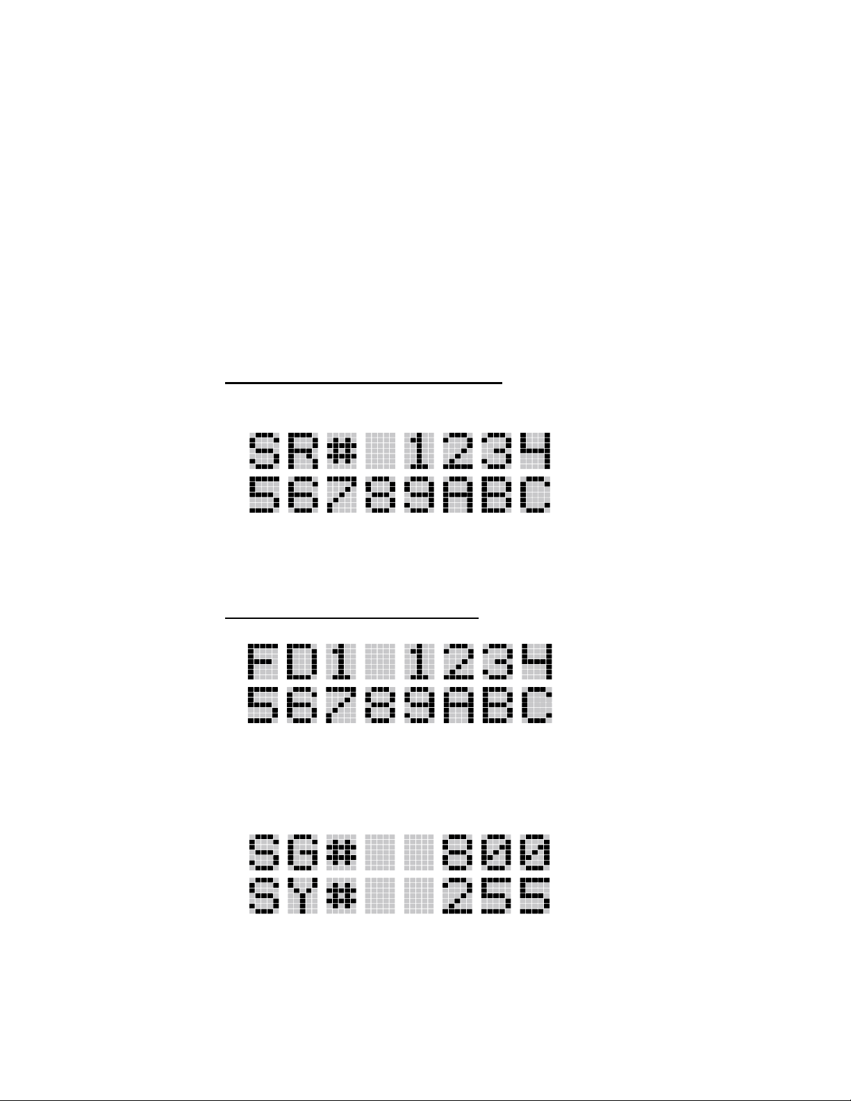
10.5.1 Serial Number ROM (12 Hex Digits)
Example:
When the user wants to enab le a feature in his radio, he will need to call M/A-COM, Inc. They
will ask for the ROM serial number. The serial number shown here is for example only.
10.5.2 Feature Encryption Data Stream
Example:
These data streams define the features the user has enabled in his radio and are required by M/ACOM, Inc. to enable other features. The data streams shown here are for example only. Note:
There are three displays: FD1, FD2, FD3. All three are required.
Number Fields
Example:
28
These number fields show the set limits of the of the user's radio as:
• SG# XXX - Maximum number of system/groups combination available
• SY# XXX - EDACS maximum trunked system limit

• CH# XXX - Maximum number of conventional channels available
The user needs to know the limits of his radio before attempting to enable other features. The
numbers shown here are for example only.
10.5.3 Features Enabled
These numbers indicate which features are enabled.
Example:
Table 10-2 lists possible features available in the user's radio.
Table 10-2: Available Feature Numbers
FEATURE
NUMBER
01 Conventional Priority Scan Standard
04 Group Scan (EDACS only) Standard
05 Priority System Scan (EDACS only) Optional
06 WAscan/ProSound™/ProScan (EDACS only) Optional
07 Dynamic Regroup (EDACS only) Optional
08 EDACS Emergency (EDACS only) Optional
09 Type 99 Encode Standard
10 Conventional Emergency Standard
12 Aegis™ Digital Voice Encryption Optional
14 DES Encryption Optional
16 Mobile Data EDACS – Standard
17 Status/Message (EDACS only) Optional
21 EDACS Security Key (ESK) Optional
22 ProFile™ (EDACS only) Optional
23 Narrowband Standard
POSSIBLE FEATURES STANDARD OR
OPTIONAL
P25 Conventional – Optional
29 ProVoice™ Optional
32 FIPS-140-2 Optional
33 P25 Common Air Interface Optional
34 Direct Frequency Entry Optional
10.6 SYSTEM/GROUP/CHANNEL SELECTION
In the following description of SYSTEM/GROUP/CHANNEL SELECTION, the term group is used for
both group and channel.
29
 Loading...