

HARRIS TR-0020-E Motorcycle install revised
Installation Manual
MM102343V1
Rev. Ap5, Apr-04
M7100IP
Mobile Radio & Control Unit
Motorcycle Installation

REVISION HISTORY
REV DATE SUMMARY OF CHANGES
A Apr. 2004 Initial release
CREDITS
EDACS is a registered trademark and PANTHER, M-PA, M-PD, MTL, TPX, PCS, M-RK,
LPE-200, and Prism are trademarks of M/A-COM, Inc.
Kawasaki is a registered trademark of Kawasaki Motors Corporation, U.S.A.
Harley-Davidson is a registered trademark of Harley-Davidson, Inc.
All other brand and product names are trademarks, registered trademarks, or service marks
of their respective holders.
NOTICE
The voice coding technology embodied in this product is protected by intellectual property
rights including patent rights, copyrights, and trade secrets of Digital Voice Systems, Inc.
The user of this technology is explicitly prohibited from attempting to decompile, reverse
engineer, or disassemble the Object Code, or in any way convert the Object Code into
human-readable form.
NOTICE
Repairs to this equipment should be made only by an authorized service technician or at a facility
designated by the supplier. Any repairs, alterations or substitutions of recommended parts made
by the user to this equipment not approved by the manufacturer could void the user’s authority to
operate the equipment in addition to the manufacturers warranty.
The software contained in this device is copyrighted by M/A-COM, Inc. Unpublished rights are
reserved under the copyright laws of the United States.
This manual is published by M/A-COM, Inc., without any warranty. Improvements and changes
to this manual necessitated by typographical errors, inaccuracies of current information, or
improvements to programs and/or equipment, may be made by M/A-COM, Inc., at any time and
without notice. Such changes will be incorporated into new editions of this manual. No part of this
manual may be reproduced or transmitted in any form or by any means,. electronic or mechanical,
including photocopying and recording, for any purpose, without the express written permission of
M/A-COM, Inc.
Copyright© 2004 M/A-COM, Inc. All rights reserved.
2

TABLE OF CONTENTS
Page
1 SAFETY SYMBOL CONVENTIONS...................................................4
2 RF ENERGY EXPOSURE INFORMATION.......................................5
2.1 RF ENERGY EXPOSURE INFORMATION.......................................5
2.1.1 Federal Communications Commission Regulations................ 6
2.2 COMPLIANCE WITH RF EXPOSURE STANDARDS...................... 6
2.2.1 Mobile Antennas......................................................................7
2.2.2 Approved Accessories............................................................. 8
2.2.3 Contact Information................................................................. 8
3 OPERATION SAFETY RECOMMENDATIONS................................9
3.1 TRANSMITTER HAZARDS............................................................... 9
3.2 SAFE DRIVING RECOMMENDATIONS........................................ 10
4 GENERAL INFORMATION............................................................... 12
4.1 RELATED DOCUMENTATION....................................................... 12
5 OPTIONS AND ACCESSORIES......................................................... 13
5.1 VENDOR DROP SHIP OPTIONS .....................................................15
5.1.1 External Headset Options...................................................... 15
5.2 HARDWARE KITS............................................................................15
5.3 USER SUPPLIED EQUIPMENT.......................................................19
5.4 POWER CONSIDERATIONS............................................................19
5.4.1 RF Power Adjustments..........................................................19
6 INSTALLATION...................................................................................21
6.1 TOOLS REQUIRED........................................................................... 21
6.2 EQUIPMENT INSTALLATION........................................................21
6.2.1 Weather Resistant Case Assembly and Installation...............21
6.2.2 Harley-Davidson Installation................................................. 24
6.3 RADIO MOUNTING BRACKETS....................................................24
7 CONTROL UNIT MOUNTING........................................................... 26
7.1.1 Control Unit And Mic Hanger Installation............................ 27
7.2 SPEAKER MOUNTING..................................................................... 29
7.3 CABLE ROUTING ............................................................................. 29
7.3.1 Power and Control Cables..................................................... 29
7.3.2 Option Cable.......................................................................... 30
7.3.3 Typical Harley-Davidson Installation.................................... 30
7.4 CABLE CONNECTIONS...................................................................33
7.4.1 Power Cable........................................................................... 34
7.4.2 Control Cable......................................................................... 34
7.4.3 Ignition Switch Option ..........................................................34
7.4.4 Accessory Cable.................................................................... 35
7.5 ANTENNA INSTALLATION............................................................35
7.5.1 General ..................................................................................35
7.5.2 Typical Motorcycle Mount Antenna Installation................... 36
8 FINAL CHECKS AND CONNECTIONS............................................37
8.1 HEADSET INSTALLATION (OPTION)...........................................37
8.1.1 Dual Radio Application (Mobile with Portable).................... 37
8.1.2 Headset Operation ................................................................. 41
9 WARRANTY.......................................................................................... 54
3
1 SAFETY SYMBOL CONVENTIONS
The following conventions are used throughout this manual to alert the user to
general safety precautions that must be observed during all phases of
operation, service, and repair of this product. Failure to comply with these
precautions or with specific warnings elsewhere in this manual violates safety
standards of design, manufacture, and intended use of the product. M/ACOM, Inc. assumes no liability for the customer’s failure to comply with
these standards.
The WARNING symbol calls attention to a procedure,
practice, or the like, which, if not correctly performed or
adhered to, could result in personal injury. Do not proceed
WARNING
CAUTION
beyond a WARNING symbol until the conditions identified
are fully understood or met.
The CAUTION symbol calls attention to an operating
procedure, practice, or the like, which, if not performed
correctly or adhered to, could result in damage to the
equipment or severely degrade the equipment performance.
The NOTE symbol calls attention to supplemental
information, which may improve system performance or
NOTE
clarify a process or procedure.
The ESD symbol calls attention to procedures, practices, or
the like, which could expose equipment to the effects of
Electro-Static Discharge. Proper precautions must be taken to
prevent ESD when handling circuit modules.
4
2 RF ENERGY EXPOSURE INFORMATION
2.1 RF ENERGY EXPOSURE AWARENESS,
CONTROL INFORMATION, AND OPERATION
INSTRUCTIONS FOR FCC OCCUPATIONAL USE
REQUIREMENTS
BEFORE USING YOUR MOBILE TWO-WAY RADIO, READ THIS
IMPORTANT RF ENERGY AWARENESS AND CONTROL
INFORMATION AND OPERATIONAL INSTRUCTIONS TO
ENSURE COMPLIANCE WITH THE FCC’S RF EXPOSURE
GUIDELINES.
NOTICE: This radio is intended for use in occupational/controlled
conditions, where users have full knowledge of their exposure and can
exercise control over their exposure to meet FCC limits. This radio
device is NOT authorized for general population, consumer, or any other
use.
Changes or modifications not expressly approved by M/ACOM, Inc. could void the user's authority to operate the
CAUTION
This two-way radio uses electromagnetic energy in the radio frequency (RF)
spectrum to provide communications between two or more users over a
distance. It uses RF energy or radio waves to send and receive calls. RF
energy is one form of electromagnetic energy. Other forms include, but are
not limited to, electric power, sunlight, and x-rays. RF energy, however,
should not be confused with these other forms of electromagnetic energy,
which, when used improperly, can cause biological damage. Very high levels
of x-rays, for example, can damage tissues and genetic material.
Experts in science, engineering, medicine, health, and industry work with
organizations to develop standards for exposure to RF energy. These
standards provide recommended levels of RF exposure for both workers and
the general public. These recommended RF exposure levels include
substantial margins of protection. All two-way radios marketed in North
America are designed, manufactured, and tested to ensure they meet
government established RF exposure levels. In addition, manufacturers also
recommend specific operating instructions to users of two-way radios. These
equipment.
5

instructions are important because they inform users about RF energy
exposure and provide simple procedures on how to control it. Please refer to
the following websites for more information on what RF energy exposure is
and how to control your exposure to assure compliance with established RF
exposure limits.
http://www.fcc.gov/oet/rfsafety/rf-faqs.html
http://www.osha.gov./SLTC/radiofrequencyradiation/index.html
2.1.1 Federal Communications Commission
Regulations
Your M/A-COM, Inc. M7100IP mobile two-way radio is designed and tested
to comply with the FCC RF energy exposure limits for mobile two-way radios
before it can be marketed in the United States. When two-way radios are
used as a consequence of employment, the FCC requires users to be fully
aware of and able to control their exposure to meet occupational
requirements. Exposure awareness can be facilitated by the use of a label
directing users to specific user awareness information. Your M/A-COM, Inc.
IP
M7100
M7100
two-way radio has an RF exposure product label. Also, your
IP
Installation and Operator’s Manuals include information and
operating instructions required to control your RF exposure and to satisfy
compliance requirements.
2.2 COMPLIANCE WITH RF EXPOSURE
STANDARDS
Your M/A-COM, Inc. M7100IP mobile two-way radio is designed and tested
to comply with a number of national and international standards and
guidelines (listed below) regarding human exposure to RF electromagnetic
energy. This radio complies with the IEEE and ICNIRP exposure limits for
occupational/controlled RF exposure environment at duty factors of up to
50% talk-50% listen and is authorized by the FCC for occupational use. In
terms of measuring RF energy for compliance with the FCC exposure
guidelines, your radio antenna radiates measurable RF energy only while it is
transmitting (talking), not when it is receiving (listening) or in standby mode.
IP
Your M/A-COM, Inc. M7100
following RF energy exposure standards and guidelines:
mobile two-way radio complies with the
• United States Federal Communications Commission (FCC), Code of
Federal Regulations; 47 CFR §§ 2 sub-part J.
• American National Standards Institute (ANSI)/Institute of Electrical
and Electronic Engineers (IEEE) C95.1-1992.
• Institute of Electrical and Electronic Engineers (IEEE) C95.1-1999.
6
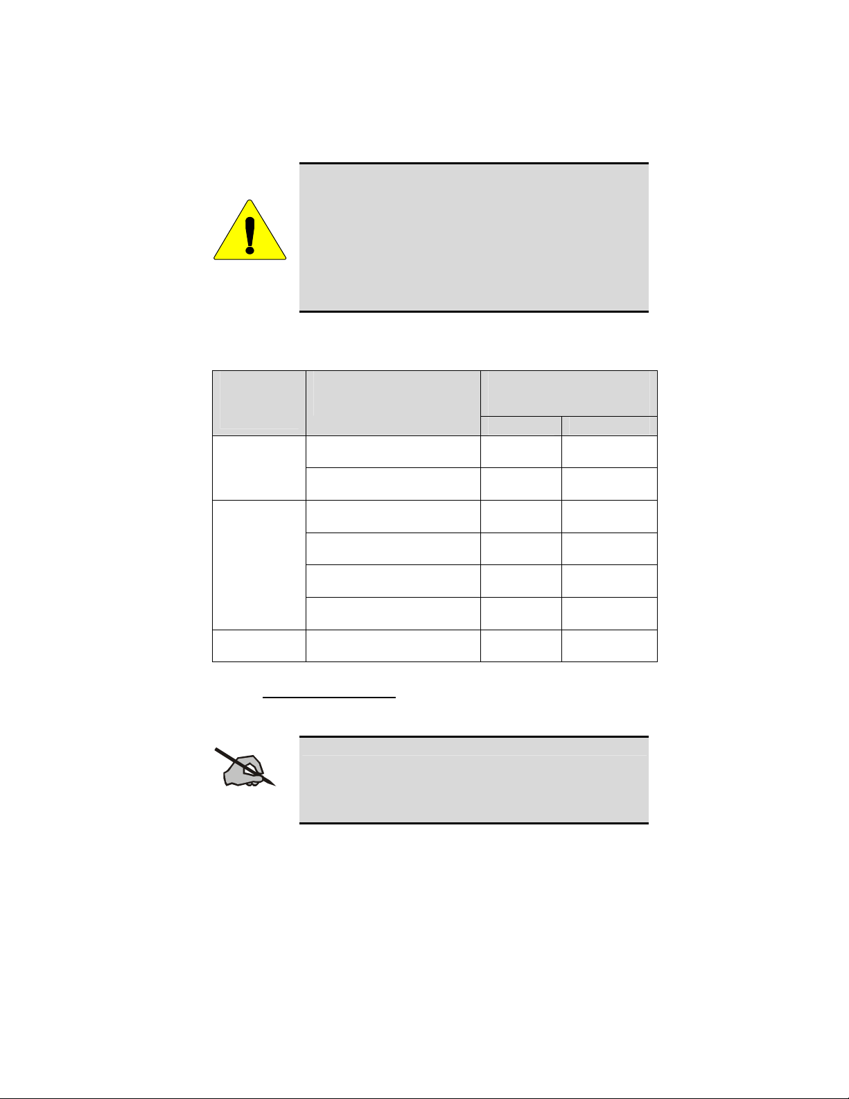
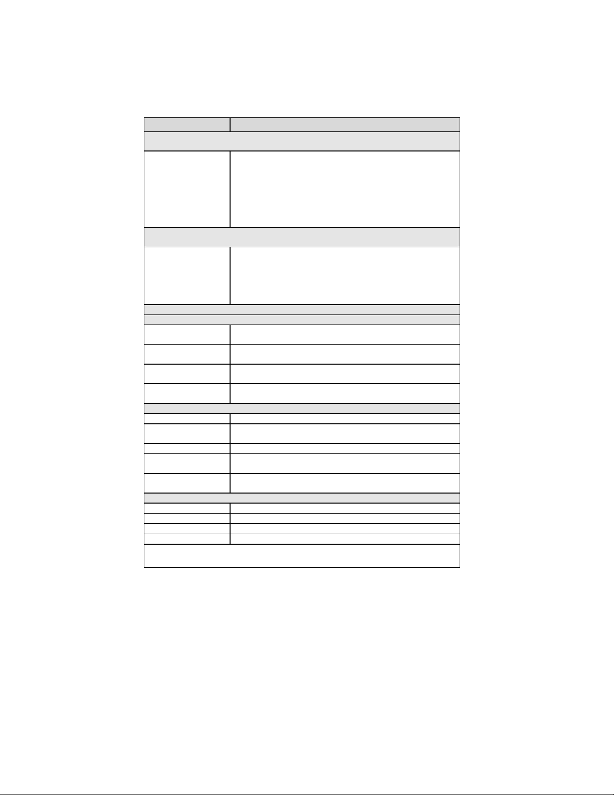
Table 2-1 lists the recommended minimum lateral distance
for a controlled environment and for unaware bystanders in
an uncontrolled environment, from transmitting types of
antennas (i.e., monopoles over a ground plane, or dipoles)
at rated radio power for mobile radios installed on a
CAUTION
motorcycle. Transmit only when unaware bystanders are at
least the uncontrolled recommended minimum lateral
distance away from the transmitting antenna.
Table 2-1: Rated Power and Recommended Minimum Lateral Distance
MOBILE
RADIO
FREQUENCY
SPLIT
UHF-H
800 MHz 35 Watts, (806 MHz, Antenna
RATED POWER OF
MOTORCYCLE-INSTALLED
MOBILE TWO-WAY RADIO
50 Watts, (378 MHz, Antenna
P/N: LE-OM406BKTNC)
50 Watts, (378 MHz, Antenna
P/N: LE-OM420BKTNC)
50 Watts, (450 MHz, Antenna
P/N: LE-OM440BKTNC)
50 Watts, (450 MHz, Antenna
P/N: LE-OM450BKTNC)
50 Watts, (450 MHz, Antenna
P/N: LE-OM470BKTNC)
50 Watts, (450 MHz, Antenna
P/N: LE-OM490BKTNC)
P/N: LE-OM806DBKTNCDS)
2.2.1 Mobile Antennas
This device must not be co-located or operating in
conjunction with any other antenna or transmitter.
NOTE
RECOMMENDED MINIMUM
LATERAL DISTANCE FROM
TRANSMITTING ANTENNA
Controlled Uncontrolled
85.23 cm 190.60 cm UHF–L
85.23 cm 190.60 cm
68.62 cm 153.43 cm
68.62 cm 153.43 cm
68.62 cm 153.43 cm
68.62 cm 153.43 cm
47.90 cm 107.20 cm
Install the radio’s antenna (refer to Table 2-1 for
frequencies and corresponding part numbers of recommended antennas) on
the end of the motorcycle case farthest away from the driver. These mobile
antenna installation guidelines are limited to motorcycles fit with the
motorcycle radio case with integral antenna grounding plane. The antenna
7

installation should additionally be in accordance with the following.
1. The requirements of the antenna manufacturer/supplier included with the
antenna.
2. Instructions in the M7100
Installation Manual, including minimum antenna cable lengths.
IP
Radio and Control Unit Motorcycle
3. The installation manual providing specific information of how to install
the antennas to facilitate recommended operating distances to all
potentially exposed persons.
Use only the M/A-COM approved/supplied antenna(s) or approved
replacement antenna. Unauthorized antennas, modifications, or attachments
could damage the radio and may violate FCC regulations.
2.2.2 Approved Accessories
This radio has been tested and meets the FCC RF guidelines when
used with the M/A-COM accessories supplied or designated for use with this
product. Use of other accessories may not ensure compliance with the FCC’s
RF exposure guidelines, and may violate FCC regulations.
For a list of M/A-COM approved accessories refer to the product manuals,
M/A-COM’s Products and Services Catalog, or contact M/A-COM at 1-800528-7711.
2.2.3 Contact Information
For additional information on exposure requirements or other information,
contact M/A-COM, Inc. at 1-800-528-7711 or at http://www.macom-
wireless.com.
8
3 OPERATION SAFETY RECOMMENDATIONS
3.1 TRANSMITTER HAZARDS
The operator of any mobile radio should be aware of
certain hazards common to the operation of radio
transmitters. A list of several possible hazards is given:
WARNING
• Explosive Atmospheres – Just as it is dangerous to fuel a vehicle with
the motor running, similar hazards exist when operating a mobile radio.
Be sure to turn the radio off while fueling the motorcycle. Do not
transport containers of fuel.
Areas with potentially explosive atmosphere are often, but not
always, clearly marked. Turn OFF your radio when in any area with
a potentially explosive atmosphere. It is rare, but not impossible that
the radio or its accessories could generate sparks.
• Interference to Vehicular Electronics Systems – Electronic fuel
injection systems, electronic anti-skid braking systems, electronic cruise
control systems, etc., are typical electronic systems that may malfunction
due to the lack of protection from radio frequency energy present when
transmitting. If the vehicle contains such equipment, cons ult the dealer
and enlist their aid in determining the expected performance of electronic
circuits when the radio is transmitting.
• Electric Blasting Caps – To prevent accidental detonation of electric
blasting caps, DO NOT use two-way radios within 1000 feet of blasting
operations. Always obey the “Turn Off Two-Way Radios” signs posted
where electric blasting caps are being used. (OSHA Standard: 1926-900)
• Liquefied Petroleum (LP) Gas Powered Vehicles – Mobile radio
installations in vehicles powered by liquefied petroleum gas with the LP
gas container in the trunk or other sealed-off space within the interior of
the vehicle must conform to the National Fire Protection Association
standard NFPA 58 requiring:
The space containing the radio equipment shall be isolated by a seal
from the space containing the LP gas container and its fittings.
Outside filling connections shall be used for the LP gas container.
The LP gas container shall be vented to the outside of the vehicle.
9

3.2 SAFE DRIVING RECOMMENDATIONS
(Recommended by AAA)
• Read the literature on the safe op eration of the radio.
• Use both hands to steer and keep the microphone in its hanger whenever
the vehicle is in motion.
• Place calls only when the vehicle is stopped.
• When talking from a moving vehicle is unavoidable, drive in the slower
lane. Keep conversations brief.
• If a conversation requires taking notes or complex thought, stop the
vehicle in a safe place and continue the call.
• Whenever using a mobile radio, exercise caution.
10
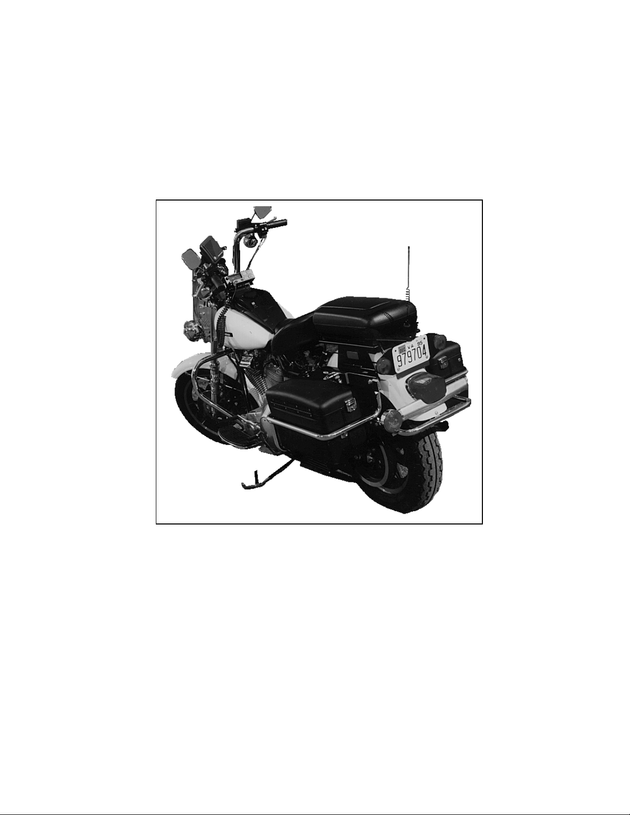
Figure 3-1: Typical M7100IP Motorcycle Installation
11
4 GENERAL INFORMATION
This manual contains instructions for installing the M7100IP mobile radio,
IP
M7100
instructions in this manual are typical installation instructions, and are not
intended to cover all makes and models of motorcycles.
Final installation of the radio equipment is left to the discretion of the radio
installer.
To simplify installation and minimize difficulties, it is suggested that the
installer read the entire manual prior to installation. Figure 3-1 shows a
typical motorcycle installation.
4.1 RELATED DOCUMENTATION
M7100IP Mobile Radio Operator’s Manual,
M7100
M7100
M7100
control unit, and associated hardware on a motorcycle. The
M/A-COM, Inc. does not assume liability for possible
degradation of the radio or motorcycle performance due to
NOTE
mounting procedures.
Scan & System................................................................. MM102341V1
IP
Mobile Radio Installation Manual,
Scan & System................................................................. MM102342V1
IP
Mobile Radio Motorcycle Installation Manual,
(50W TX and Below) ......................................................MM102343V1
IP
Mobile Radio Maintenance Manual
UHF (378-430 MHz and 450-512 MHz).........................MM102346V1
VHF (136-174 MHz).......................................................MM102345V1
800 MHz (806-870 MHz)................................................MM102347V1
12
5 OPTIONS AND ACCESSORIES
Some of the options and accessories applicable to motorcycle installations are
defined below in Table 5-1. NOTE: The M7100
IP
mobile radio, control unit,
accessory kits and microphone are ordered separately and then modified for
motorcycle applications. Applicable hardware is included with each option.
Refer to M/A-COM’s Products and Services Catalog for the full line of
options and accessories.
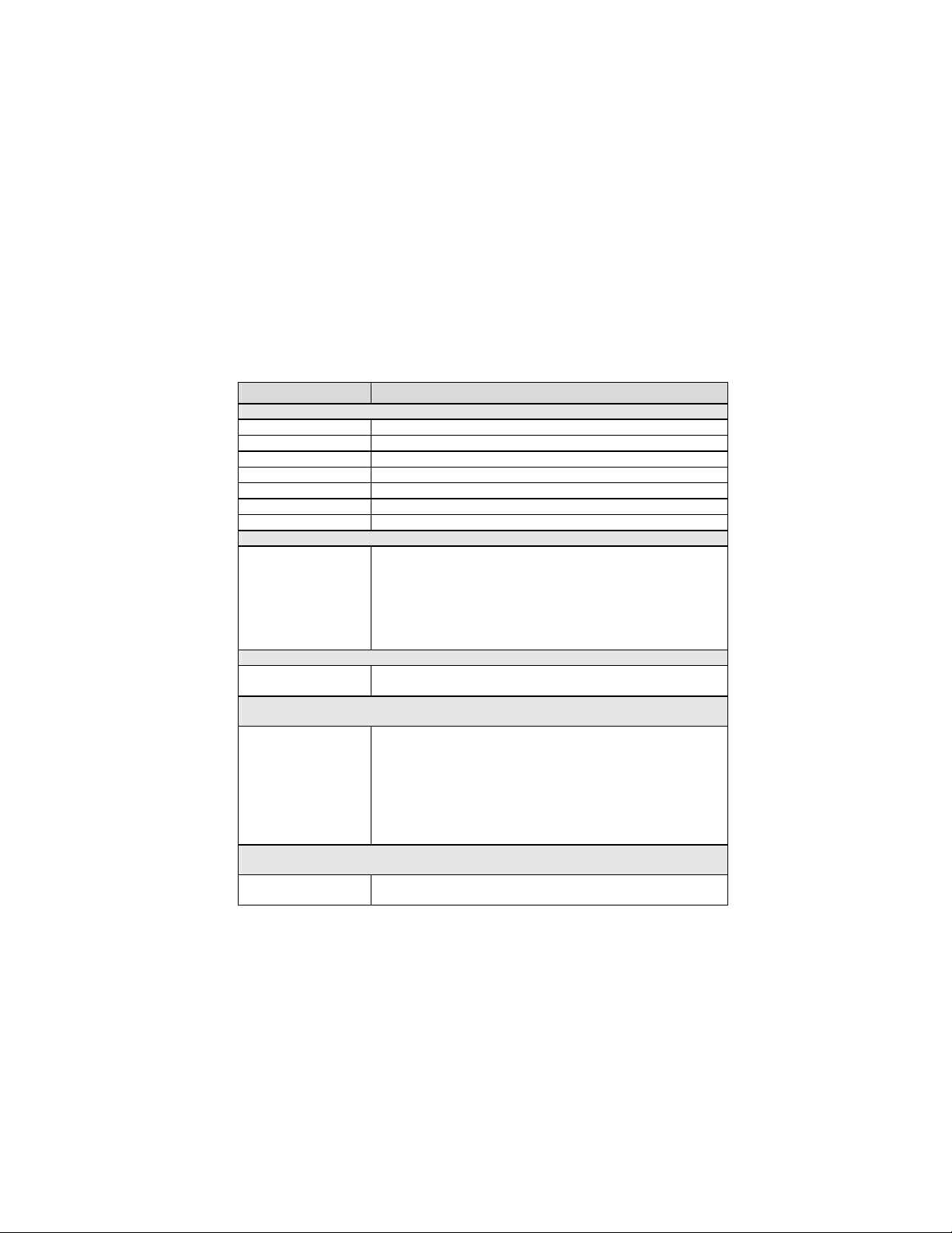
Table 5-1: M7100
OPTION DESCRIPTION
ANTENNAS
LE-OM406BK/TNC Antenna, ¼ Wave, Vertical, TNC, 403-420 MHz
LE-OM420BK/TNC Antenna, ¼ Wave, Vertical, TNC, 420-440 MHz
LE-OM440BK/TNC Antenna, ¼ Wave, Vertical, TNC, 440-450 MHz
LE-OM450BK/TNC Antenna, ¼ Wave, Vertical, TNC, 450-470 MHz
LE-OM470BK/TNC Antenna, ¼ Wave, Vertical, TNC, 470-490 MHz
LE-OM490BK/TNC Antenna, ¼ Wave, Vertical, TNC, 490-512 MHz
LE-OM806DBKTNCDS Whip Antenna, Stranded Coax (800 MHz)
REMOTE MOUNT ACCESSORIES, MOTORCYCLE
MAHG-ZN6D Includes remote mount radio front cover, front cover logo label,
REMOTE MOUNT ACCESSORIES, MOTORCYCLE W/O ACCESSORY CABLE
MAHG-ZN6E Same as MAHG-ZN6D above except omit the motorcycle accessory
HAND HELD CONTROLLER (WITHOUT SIREN) ACCESSORIES, REMOTE MOUNT
MOTORCYCLE
MAHG-ZN6F Includes Hand Held Controller (HHC) with mounting bracket, HHC
HAND HELD CONTROLLER (WITHOUT SIREN) ACCESSORIES, REMOTE MOUNT
MOTORCYCLE WITH NO ACCESSORY CABLE
MAHG-ZN6G Same as MAHG-ZN6F above without the motorcycle accessory
IP
Motorcycle Mounted Option and Accessory Kits
motorcycle accessory cable, motorcycle control cable, motorcycle
power cable, microphone hanger kit, motorcycle radio mounting kit,
motorcycle control unit mounting kit (includes special mic hanger ),
motorcycle radio case, power filter, motorcycle radio case bracket,
antenna mounting bracket, 3 hardware kits, TX power turn down
label, and motorcycle installation manual.
cable.
interface cable, remote radio front cover, front cover logo label,
motorcycle accessory cable, motorcycle control cable, motorcycle
power cable, motorcycle radio mounting kit, mobile speaker,
motorcycle radio case, power filter, motorcycle radio case bracket,
antenna mounting bracket, 3 hardware kits, TX power turn down
label, accessory connector cover, motorcycle installation manual, and
HHC operator and installation manuals.
cable.
13
OPTION DESCRIPTION
HAND HELD CONTROLLER (WITH SIREN) ACCESSORIES, REMOTE MOUNT
MOTORCYCLE
MAHG-ZN6H Includes Hand Held Controller (HHC) with mounting bracket, HHC
interface cable (for siren), remote radio front cover, front cover logo
label, motorcycle accessory cable, motorcycle control cable,
motorcycle power cable, motorcycle radio mounting kit, mobile
speaker, motorcycle radio case, power filter, motorcycle radio case
bracket, antenna mounting bracket, 3 hardware kits, TX power turn
down label, accessory connector cover, motorcycle installation
manual, and HHC operator and installation manuals.
FIELD UPGRADE OPTION: MOTORCYCLE CONVERSION, FIELD UPGRADE, REMOTE MOUNT
RADIO
MAHG-ZN6R Includes motorcycle accessory cable, motorcycle control cable,
motorcycle power cable, motorcycle radio mounting kit, motorcycle
control unit mounting kit (includes special mic hanger), motorc ycle
radio case, power filter, motorcycle radio case bracket, antenna
mounting bracket, 3 hardware kits, and motorcycle installation
manual.
VENDOR DROP SHIP OPTIONS
MOTORCYCLE HEADSET OPTIONS - MOBILE RADIO (REQUIRES EXTENDED OPTION CABLE)
SM-KA-13 Helmet Kit, External mount with Speaker and Noise Canceling
Microphone
SM-KA-23 Helmet Kit, External Mount with Two Speakers and Noise Canceling
Microphone
SM-KA11-FG Half Helmet Kit, Seer 1608, with Speaker and Noise Canceling
Microphone
SM-KA21-FG Half Helmet Kit, Seer 1608, with Two Speakers and Noise Canceling
Microphone
HEADSET KIT INTERFACE CABLE OPTIONS (INTERFACE TO MOTORCYCLE)
SM-MCK-71GT Helmet Kit Interface Cable with Pushbutton PTT (Kawasaki®)
SM-MCK-72GT Helmet Kit Interface Cable with Rocker PTT Switch and Channel
Guard Disable (Kawasaki)
SM-MCH-71GT Helmet Kit Interface Cable with Pushbutton PTT (Harley-Davidson®)
SM-MCH-72GT Helmet Kit Interface Cable with Rocker PTT Switch and Channel
Guard Disable (Harley-Davidson)
SM-MCH-73GT Helmet Kit Interface Cable with Rocker/PTT/PA Switch and Channel
Guard Disable (Harley-Davidson)
HEADSET KIT INTERFACE CABLE OPTIONS (MOBILE/PORTABLE RADIO CONFIGURATION)
SM-25-0694 Extender Cable, Helmet to Harness
SM-CA-3G5 Cable, Belt Box, JAGUAR™ 700P/Pi and P7100IP
SM-CA-3GY Cable, Belt Box, LPE-200™
SM-CA-3GV Cable, Belt Box, M-RK™
Refer to M/A-COM’s Products and Services Catalog for the full line of options and accessories
available for use with the M7100
IP
mobile radio.
14

5.1 VENDOR DROP SHIP OPTIONS
There are external headsets available through M/A-COM vendors (refer to the
Options and Accessories list in Table 5-1).
5.1.1 External Headset Options
There are two different applications for the Headset. One is for use with just
the M7100
radio and a portable radio. See Section 8.1.
IP
mobile radio and the other is for use with the M7100IP mobile
In addition, Belt Box Assembly Interfaces are available for use with the dual
application that allows the headset to be used with the M7100
IP
mobile radio
and a portable radio.
5.2 HARDWARE KITS
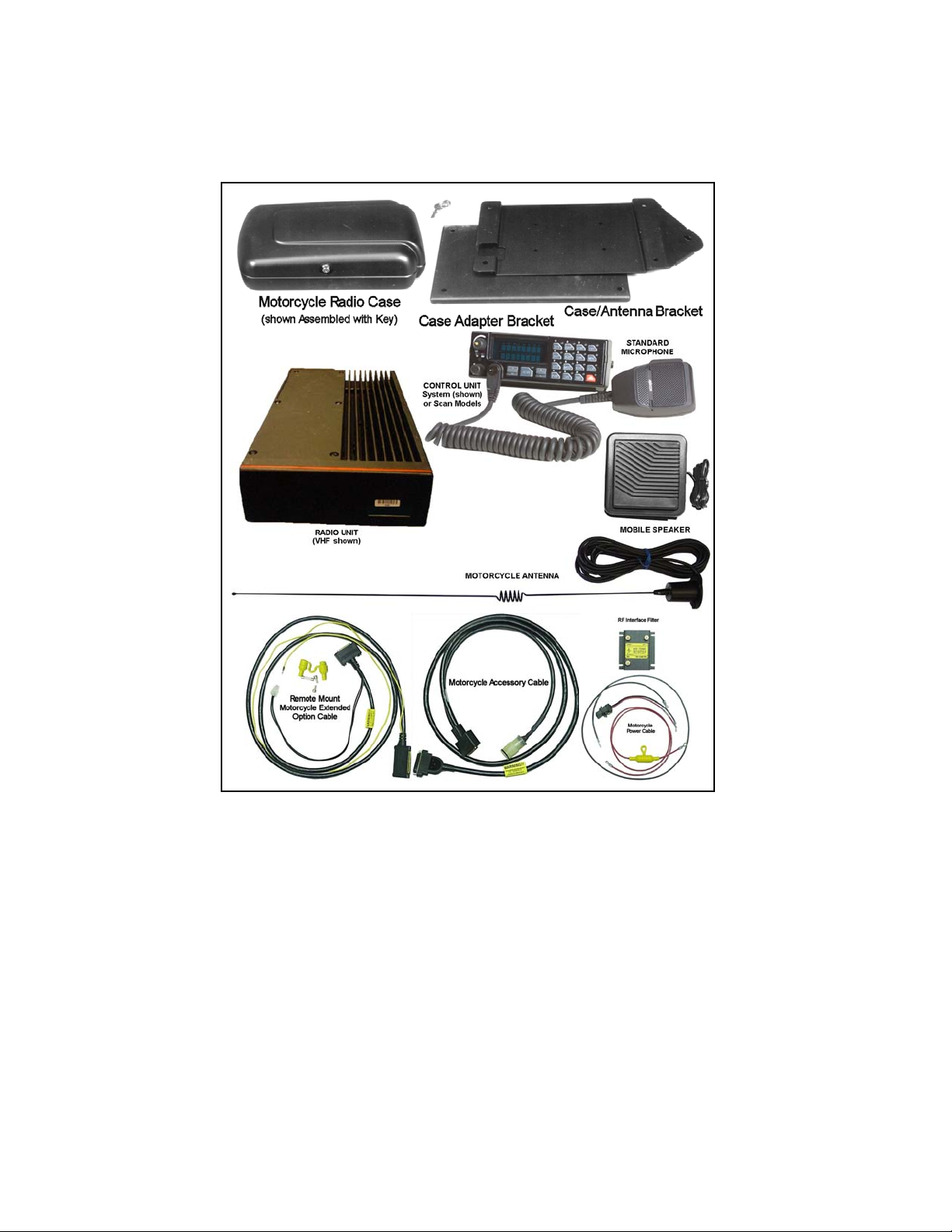
The typical motorcycle mount application requirements are shown in Figure
5-1 (radio, control unit, microphone, and antenna are all ordered separately).
Hardware Kits 350A1396G1-G4 are shown in Figure 5-2 and Figure 5-3.
Hardware kit 350A1396G1 is used to factory-install the radio mounting
bracket and alternator whine reject filter to the weather-resistant case.
Hardware kits, 350A1396G2-G4, are used by the customer in the field to
mount the case and control head to the motorcycle (and may require the
optional Harley-Davidson adapter bracket).
IP
• MIL-STD weather-resistant locking M7100
antenna ground plane
• Motorcycle Case hardware kit
• Motorcycle Radio Mounting bracket and hardware
• Case/Antenna bracket
• Case/Antenna Mount hardware kit
• Control Unit Mount hardware kit
• Case Adapter bracket (for Harley-Davidson motorcycles)
radio case with integral
• Case Adapter Mount hardware kit
• RF Interface filter
• MIL-STD weatherproof speaker
• Radio-to-Control Unit Motorcycle cable
• Motorcycle Accessory cable
• Power/Control cable
15
16
Figure 5-1: Typical Motorcycle Kit
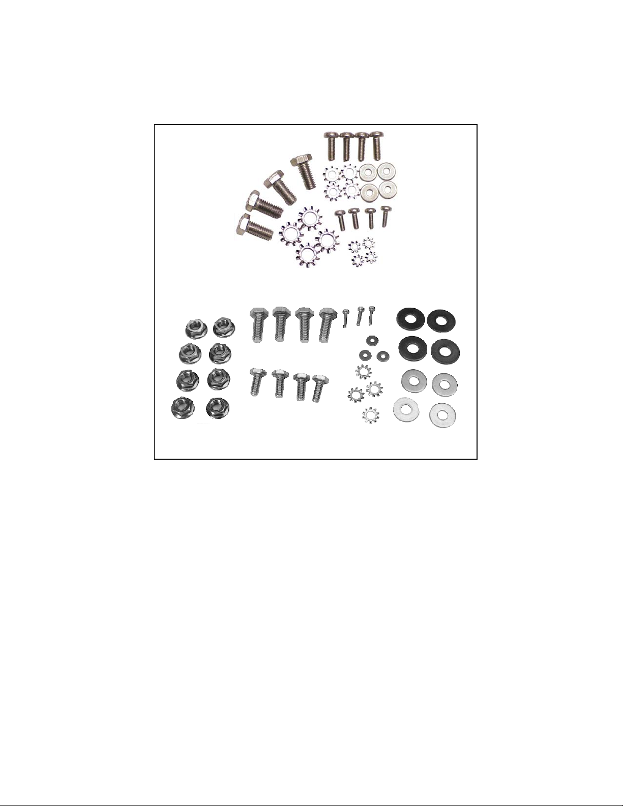
Hardware Application Kit 350A1396G1
Case/Antenna Assembly Hardware Kit 350A1396G2
Figure 5-2: Hardware Installation Kits for Harley-Davidson Motorcycles
17
 Loading...