

HARRIS TR-0017-E Power Supply
Maintenance Manual
LBI-38550D
Site Equipment Power Supply
19A149978P1 - 120 VOLT/60 Hz
19A149978P2 - 230 VOLT/50 Hz
CAUTION
THESE SERVICING INSTRUCTIONS ARE FOR USE BY QUALIFIED
PERSONNEL ONLY. TO AVOID ELECTRIC SHOCK DO NOT PERFORM
ANY SERVICING OTHER THAN THAT CONTAINED IN THE OPERATING
INSTRUCTIONS UNLESS YOU ARE QUALIFIED TO DO SO. REFER ALL
SERVICING TO QUALIFIED SERVICE PERSONNEL.
WARNING: TO PREVENT FIRE OR ELECTRIC SHOCK HAZARD.
DO NOT EXPOSE THIS PRODUCT TO RAIN OR MOISTURE.
CAUTION:
TO PREVENT ELECTRIC SHOCK DO NOT USE THIS (POLARIZED)
PLUG WITH AN EXTENSIO N CORD, RECEPTACLE OR OTHER OUTLET
UNLESS THE BLADES CAN BE FULLY INSERTED TO PREVENT BLADE
EXPOSURE.

LBI-38550D
TABLE OF CONTENTS
SPECIFICATIONS . . . . . . . . . . . . . . . . . . . . . . . . . . . . . . . . . . . . . . . . . . . . . . . . . 3
IMPOR TANT SAFETY INFORMATION . . . . . . . . . . . . . . . . . . . . . . . . . . . . . . . . . . . . . 4
DESCRIPTION . . . . . . . . . . . . . . . . . . . . . . . . . . . . . . . . . . . . . . . . . . . . . . . . . . . 6
CIRCUIT ANALYSIS . . . . . . . . . . . . . . . . . . . . . . . . . . . . . . . . . . . . . . . . . . . . . . . . 6
MAINTENANCE . . . . . . . . . . . . . . . . . . . . . . . . . . . . . . . . . . . . . . . . . . . . . . . . . . 7
OUTLINE DIAGRAM . . . . . . . . . . . . . . . . . . . . . . . . . . . . . . . . . . . . . . . . . . . . . . . 11
ASSEMBLY DIAGRAMS
60 Hz Power Supply . . . . . . . . . . . . . . . . . . . . . . . . . . . . . . . . . . . . . . . . . . . . . 12
50 Hz Power Supply . . . . . . . . . . . . . . . . . . . . . . . . . . . . . . . . . . . . . . . . . . . . . 16
SCHEMATIC DIAGRAMS
60 Hz Power Supply . . . . . . . . . . . . . . . . . . . . . . . . . . . . . . . . . . . . . . . . . . . . . 13
50 Hz Power Supply . . . . . . . . . . . . . . . . . . . . . . . . . . . . . . . . . . . . . . . . . . . . . 17
PART LISTS
60 Hz Power Supply . . . . . . . . . . . . . . . . . . . . . . . . . . . . . . . . . . . . . . . . . . . . . . 15
50 Hz Power Supply . . . . . . . . . . . . . . . . . . . . . . . . . . . . . . . . . . . . . . . . . . . . . 18
Page
SAFETY NOTES
• The means of disconnecting power from a station cabinet is the cabinet power supply plug.
• When conducti ng rep a ir/maintenance, disconnect the cabinet power suppl y plug from the AC sou rce.
• In European applications, equipment must be installed in a closed cabinet.
• Only replace components with components specified by M/A-COM Private Radio Systems.
NOTICE!
Repairs to this equipment should be made only by an authorized service technician or facility designated by the supplier.
Any repairs, alterations or substitution of recommended parts made by the user to this equipment not approved by the
manufacturer could void the user’s authority to operate the equip ment in addition to the manufacturer’s warranty.
NOTICE!
The software contained in this device is copyrighted by M/A-COM Private R a d io Systems, Inc. Unpublished right s are
reserved under the copyright laws of the United States.
This manual is published by M/ A-COM Private Radio Syst ems , I nc ., without any warranty. Improvements and changes t o
this manual necessitated by typographical errors, inaccuracies of current information, or improvements to programs and/or
equipment, may be made by M/A-COM Pri v at e R a dio S yst em s, Inc., at an y time and w ithout notice. Such changes will
be incorporated into new editions of this manual. No part of this manual may be reproduced or transmitted in any form or by
any means, electronic or mechanical, including photocopying and recording, for any purpose, without the express written
permission of M/A-COM Private Radio Systems, Inc.
Copyright© 1990 - 2002 M/A-COM Private Radio Systems, Inc. Al l r ights reserved.
2

SPECIFICATIONS*
OUTPUT VOLTAGE
Transmit and Receive Simultaneously 13.2 Vdc ±0.6 Vdc @ 29 Amp s (F 801 B)
13.2 Vdc ±0.6 Vdc @ 4 A mps (J80 1)
Receive only < 16.0 Vdc @ 3 Amps (J801)
LBI-38550D
Transmit only
(For 225 watt PA option )
INPUT VOLTAGE 121 Vac ±20% (6 0 Hz ve rs i o n)
INPUT FREQUENCY 60 Hz ±2 Hz (60 Hz version)
Note: For every + 1.0% change in the input frequency, the output voltage will not vary more than + 1.6% from the
output voltage measured at the nominal input line frequency.
INPUT LINE SU RGE PROTECTION 150 V rated MOV (60 Hz vers io n)
DUTY CYCLE
For 0-33 Amp o utp ut 100% (Continuous Duty)
OUTPUT VOLTAGE RIPPLE < 100 mV p-p @ 25°C
OUTPUT TRANSIENT RESPONSE
Overshoot
Undershoot
13.2 Vdc ±0.6 Vdc @ 33 Amps (F8 01B)
230 Vac ±15% (50 Hz version)
50 Hz ±2 Hz (50 Hz version)
275 V rated MOV (50 Hz version)
< 200 mV p-p @ -30°C
Not to exceed 18 Volts
Not less than 11 Volts
EFFICIENCY > 70% @ rated TX/RX load current and nominal line volt-
age
FUSE CAPABILITY
Input 10 Amp (60 Hz vers io n)
(2) 5 Amp (50 H z version)
Output 5 Amp (Low Current Port)
40 Amp (High Curre nt P ort)
DIMENSIONS (HxWxD) 5.25" x 19" x 10.35"
WEIGHT 45 lbs.
OPERATING ENVIRONMENT -30°C To +60°C
* These specifications are intended primarily for the use of the service personnel. Refer to the appropriat e Specification
Sheet for the complete specifications.
3

LBI-38550D
IMPORTANT SAFETY INFORMATION
1. SAVE THIS MANUAL - It contains important safety
and operating instructions.
2. Bef ore using the product, please follow and adhere to
all warnings, safety and operating instructions located
on the product and in the manual.
3. DO NOT expose product to rain, snow or other type of
moisture.
4. Care should be taken so objects do not fall or liquids do
not spill into the product.
5. DO NOT expose product to extreme temperatures.
6. DO NOT use auxiliary equipment not recommended or
sold by the manufacturer. To do so may result in a risk
of fire, electric shock or injury to persons.
7. To reduce risk of damage to electrical cord, pull by plug
rather than cor d when disconnecting unit.
8. Make sure the cord is located so it will not be stepped
on, tripped over or otherwise subjected to damage or
stress.
9. An extension cord should not be used unless absolutely
necessary. Use of an improper extension cord could result in a risk of fire and electric shock. If an extension
cord must be used, make sure:
a. That pins on the plug of the extension cord are the
same number, size and shape as those of the plug on
the power supply.
b. That the extension cord is properly wired in good
condition.
c. That the wire size is large enough for AC ampere rat-
ing of unit.
10. DO NOT operate unit with a damage d c ord or plug. Replace the dama ged cord immediat el y.
11. DO NOT operate this product in an explosive atmosphere unless it has been specifically certified for such
operation.
12. To reduce risk of electric shock, unplug unit from outlet
before attem pti n g an y maintenance or c leaning.
13. D O NOT op erate this product with covers or panels removed.This unit does not contain any user serviceable
components.
14. Use only fuses of the correct type, voltage rating and
current rating as speci fied in the parts list. Failure to do
so can result in fire hazard.
15. GROUNDING AND AC POWER CORD CON-
NECTION - To reduce risk of electrical shock us e o nly
a properly grounded outlet. The unit is equipped with
an electric cord having an equipment - grounding conductor an d a grou nd ing plu g. Be sur e th e o utle t i s pr operly installed and grounded in accordance with all local
codes and ordinances.
16. DANGER - Never alter the AC cord or plug. Plug into
an outlet properly wired by a qualified electrician. Improper connection or loss of ground connection can result in risk of an electrical shock.
17. The Model 19A149 978P2 is fo r use on a ci rcui t havin g
a nominal rating of 230 Vac and is factory equipped
with a specifi c electric cord to permit connection to an
acceptable electric circuit. A plug meeting local electrical codes must be supplied by the customer. Make sure
the unit is connected to an outlet having the same configuration as the plug. No adapter should be used with
this unit.
NOTE
A ferroresonant power supply is designed to work specifically at a given frequency. The 60 and 50 Hz supplies should be us ed at their nomina l fr equency ±2 Hz.
4
LBI-38550D
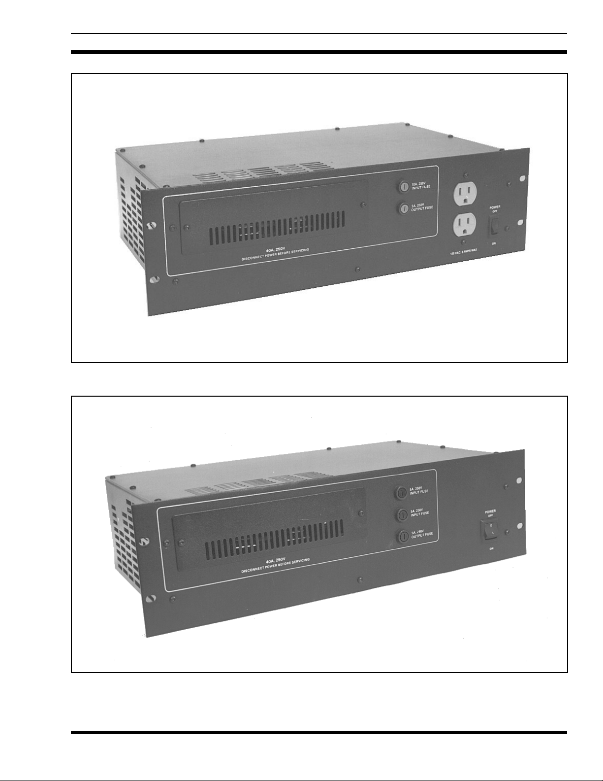
Figure 1 - 60 Hz Power Supply (19A149978P1, Rev. B)
Figure 2 - 50 Hz Power Supply (19A149978P2, Rev. A)
5

LBI-38550D
DESCRIPTION
The M/A-COM MASTR II Site Equipment Power
Supply provides up to 435 watts to power the site equipment receiver, systems circuitry, and transmitter. The power
supply normally will be used to provide power t o a MA S TR
II Site Equipment with a maximum of 29 Amps to the
power amplifier and 4 Amps for the Receiver/systems circuitry. The supply can also optionally be used to po wer a
225 watt power amplifier. In this case the supply is connected only to the power amplifier and will provide a maximum of 33 Amps.
The 60 Hz Model (19A149978P1) operates from a
nominal 121 Vac, 60 Hz source. If a 208/ 2 20 / 24 0 Vac 60 Hz
Source is to be used, an external step-down transformer
(similar to 19C307 14 8P 1 ) mu s t be us ed with the 978P 1 s u pply. The 50 Hz Model (19A149978P2) provides the same
outputs as the ’978P1 supply but operates from a nominal
230 Vac, 50 Hz source. The output voltage will change a
maximum of + 1.6% for each + 1.0% change in the input
line frequency.
NOTE
A ferroresonant power supply is designed to work specifically at a given frequency. The 60 and 50 Hz supplies should be us ed at their nomina l fr equency ±2 Hz.
The power supply’s step-down ferroresonant transformer provides excellent line voltage regulation. For the
rated input line voltage range (±20% for P1 ±15% for P2),
the output voltage will not vary more than 2 %. A ferroresonant power supply provides inherently excellent l ine volt age
surge protection, and reduced parts count for high reliability.
No active semiconductor devices are used which could reduce reliability.
The output voltage will vary depending on the load current that the supply is being asked to source. As the load
current rises, the output voltage will drop. Typically the output voltage will be 13.2 volts for a 33 Amp load, less than
16.0 volts for a 3 Amp load, and less than 16.7 volts for no
load.
The operation and servicing of the power supply are
completely accessible from the front. The ON/OFF switch
and all fuses are located on the front panel. The low profile
slot type fuse holders contain the primary fuse F1 (F1 & F4
for 978P2) and the low current output fuse F3. The high
current output fuse F2 is mounted behind the front panel
fuse cover. The primary fuse F1 (F1 & F4 for 978P2) protects the input wiring to the ferroresonant transformer (10
Amps for P1, 5 Amps each for P2). The output fuses F2 (40
Amps) and F3 (5 Amps) provide external overload protection.
The 60 Hz supply provides a courtesy dual AC receptacle. Th e primary line current fuse ( F1) also provides ov ercurrent protection for the dual receptacle. The 60 Hz supply
draws 5 Amps under nominal conditions and 7 Amps under
all extremes. Thus, the dual courtesy receptacles are rated to
provide a line curr en t o f 3 Amp s .
CIRCUIT ANALYSIS
In the 60 Hz power supply (978P1), the ON/OFF switch
(S1) provides line voltage to the power supply through the
primary line fuse F1. In the Rev. B version, line voltage
flows through F1 to the courtesy receptacles prior to S1.
This allows line voltage to always be available at the receptacles. In previous models (Rev. A and earlier), S1 applies
line voltage to F1 and the courtesy receptacles in turn. Current then flows through the primary of step-down transformer (T1) via the 200°C thermal fuse. The thermal fuse
would only open in the unlikely event that an internal short
would develop in the transformer. The Varistor (VR1 - 150
V rating) provides additional input line voltage suppression.
In the 50 Hz power supply (978P2), the ON/OFF switch
(S1) is a DPST type switching both primary AC lines. In a ddition, both input lines have 5 Amp fuses (F1 and F4). The
Varistor (VR1 - 275 V rating) provides additional input line
voltage suppression. When power is applied, current flows
through the primary of step-down transformer (T1) via the
200°C thermal fuse. As in the 60 Hz model, the thermal fuse
will open if the transformer develops an internal short.
The step-down transformer is a ferroreson an t typ e wh ich
has inherently good input line voltage regulation - eliminating the need for additional high-current regulators. C1
serves as a resonating capacitor across the secondary taps of
the transformer.
The transformer steps the input voltage down to approximately 14 volts (for a 33 Amp load) and 16 volts (for a
3 Amp load). It then applies the stepped-down voltage to the
full wave rectifier circuitry consisting of D1A,B through
D3A,B and the h i gh current filter. The rectifiers are dual diode packages and ar e mo un ted on he at si nk HS1.
The high current filter consists of C2-C7 and L1. It is
designed to reduce the output ripple to less than 100 mV p-p
for any current load up to 33 Amps. It also keeps transient
responses greater than 11 and less than 18 volts. Resistor R1
is a 10 ohm, 50 watt resistor that serves two functions. One,
it acts as a bleeder resistor to discharge the capacitors when
the supply is turned off. Two, it provides a mi nimu m curr ent
6
 Loading...