

HARRIS TR-0013-E User Manual
Operator’s Manual
MM101332V1
Rev. Gp1, Jan-05
P7100IP Series
Portable Radios
REVISION HISTORY
REV DATE DESCRIPTION
R1A Mar 2003 Initial release
R2A Jun 2003 Added UHF—H (4W) and P25 functionality
R3A Feb 2004 Added UHF-L (4W)
D Feb 2004 Added CE Mark and safety symbol conventions
E May 2004 Improved detail in operating instructions
F Nov 2004 Added RU101219V71-V73 information. Updated batter y
G Jan 2005 Add marine channel information and change lapel mic earphone.
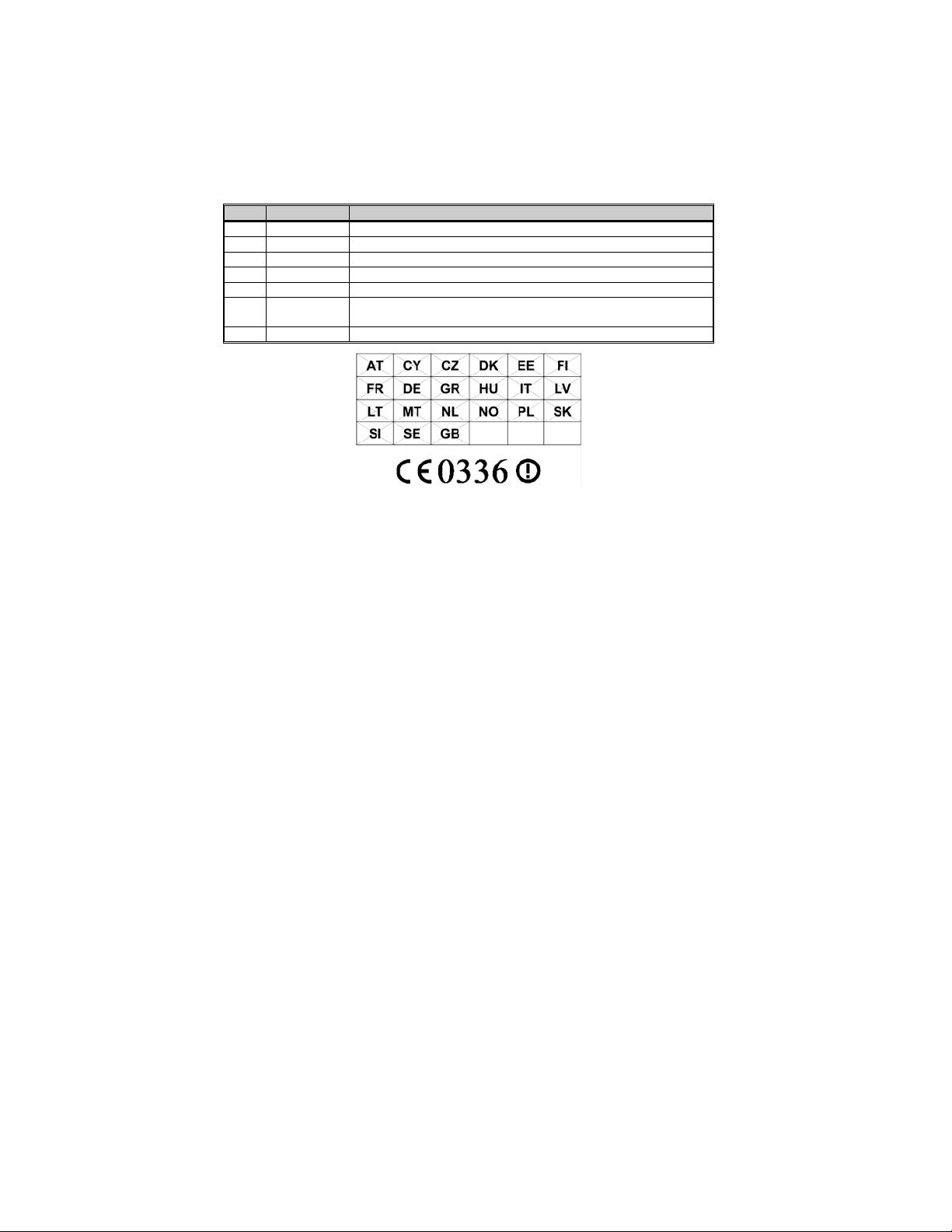
information and CE marking information.
NOTICE!
This device is a RF transceiver intended for land mobile radio applications. The device may have
use restrictions, which require that the national authority be contacted for any system licensing
requirements, frequency use, allowable power level, etc.
M/A-COM Technical Publications would particularly appreciate feedback on any errors found in
this document and suggestions on how the document could be improved. Submit your comments
and suggestions to:
Wireless Systems Business Unit
M/A-COM, Inc.
Technical Publications
221 Jefferson Ridge Parkway
Lynchburg, VA 24501
or
fax your comments to: (434) 455-6851
or
e-mail us at: techpubs@tycoelectronics.com
NOTICE!
The software contained in this device is copyrighted by M/A-COM, Inc. Unpublished rights are
reserved under the copyright laws of the United States.
This device is made under license under one or more of the following U.S. Patents: 4,590,473;
4,636,791; 5,148,482; 5,185,796; 5,271,017; 5,377,229; 4,716,407; 4,972,460; 5,502,767;
5,146,497; 5,164,986; 5,185,795.
The voice coding technology embodied in this product is protected by intellectual property rights
including patent rights, copyrights, and trade secrets of Digital Voice Systems, Inc. The user of
this technology is explicitly prohibited from attempting to decompile, reverse engineer, or
disassemble the Object Code, or in any other way convert the Object Code into human-readable
form.
EDACS is a registered trademark and ProScan, ProSound, and Failsoft are trademarks of M/ACOM, Inc.
All other product and brand names are trademarks, registered trademarks, or service marks of
their respective holders.
This manual is published by M/A-COM, Inc., without any warranty. Improvements and changes to this manual necessitated by
typographical errors, inaccuracies of current information, or improvements to programs and/or equipment, may be made by M/A-
COM, Inc., at any time and without notice. Such changes will be incorporated into new editions of this manual. No part of this
manual may be reproduced or transmitted in any form or by any means, electronic or mechanical, including photocopying and
recording, for any purpose, without the express written permission of M/A-COM, Inc.
Copyright © 2003-2004 M/A-COM, Inc. All rights reserved.
2
3

TABLE OF CONTENTS
Page
SAFETY TRAINING INFORMATION............................................5
SAFETY CONVENTIONS................................................................7
OPERATING TIPS ............................................................................8
MARITIME CHANNELS................................................................10
BATTERY DISPOSAL....................................................................11
INTRODUCTION............................................................................12
OPTIONS AND ACCESSORIES....................................................13
USER INTERFACE.........................................................................15
CONVENTIONAL OPERATION...................................................26
BASIC OPERATION.......................................................................27
TRUNKED OPERATION................................................................38
PROJECT 25 (P25) CONVENTIONAL OPERATION...................54
OPERATION FOLLOWING WATER CONTACT........................57
CHANGING THE BATTERY PACK .............................................58
BATTERY WARRANTY................................................................62
WARRANTY...................................................................................63
4
SAFETY TRAINING INFORMATION
The M/A-COM P7100IP portable radio generates RF
electromagnetic energy during transmit mode. This
radio is designed for and classified as “Occupational
Use Only,” meaning it must be used only during the
course of employment by individuals aware of the
WARNING
The P7100
IP
portable radio has been tested and complies with the FCC RF
exposure limits for “Occupational Use Only.” In addition, this M/A-COM
radio complies with the following Standards and Guidelines with regard to RF
energy and electromagnetic energy levels and evaluation of such levels for
exposure to humans:
• FCC OET Bulletin 65 Edition 97-01 Supplement C, Evaluating
Compliance with FCC Guidelines for Human Exposure to Radio
Frequency Electromagnetic Fields.
• American National Standards Institute (C95.1 – 1992), IEEE Standard for
Safety Levels with Respect to Human Exposure to Radio Frequency
Electromagnetic Fields, 3 kHz to 300 GHz.
• American National Standards Institute (C95.3 – 1992), IEEE
Recommended Practice for the Measurement of Potentially Hazardous
Electromagnetic Fields – RF and Microwave.
hazards and the ways to minimize such hazards. This
radio is NOT intended for use by the “General
Population” in an uncontrolled environment.
RF EXPOSURE GUIDELINES
To ensure that exposure to RF electromagnetic energy is
within the FCC allowable limits for occupational use,
CAUTION
• DO NOT operate the radio without a proper antenna attached, as this may
damage the radio and may also cause the FCC RF exposure limits to be
exceeded. A proper antenna is the antenna supplied with this radio by
M/A-COM or an antenna specifically authorized by M/A-COM for use
with this radio. (Refer to Table 2: Options and Accessories)
• DO NOT transmit for more than 50% of total radio use time (“50% duty
cycle”). Transmitting more than 50% of the time can cause FCC RF
exposure compliance requirements to be exceeded. The radio is
transmitting when the “TX” indicator appears in the display. The radio
will transmit by pressing the “PTT” (Push-To-Talk) button.
always adhere to the following guidelines:
5
• Always transmit using low power (refer to High/Low Power Adju stment
section) when possible. In addition to conserving battery charge, low
power can reduce RF exposure.
• ALWAYS use M/A-COM authorized accessories (antennas, batteries,
belt clips, speaker/mics, etc). Use of unauthorized accessories may cause
the FCC Occupational/Controlled Exposure RF compliance requirements
to be exceeded. (Refer to Table 2: Options and Accessories.)
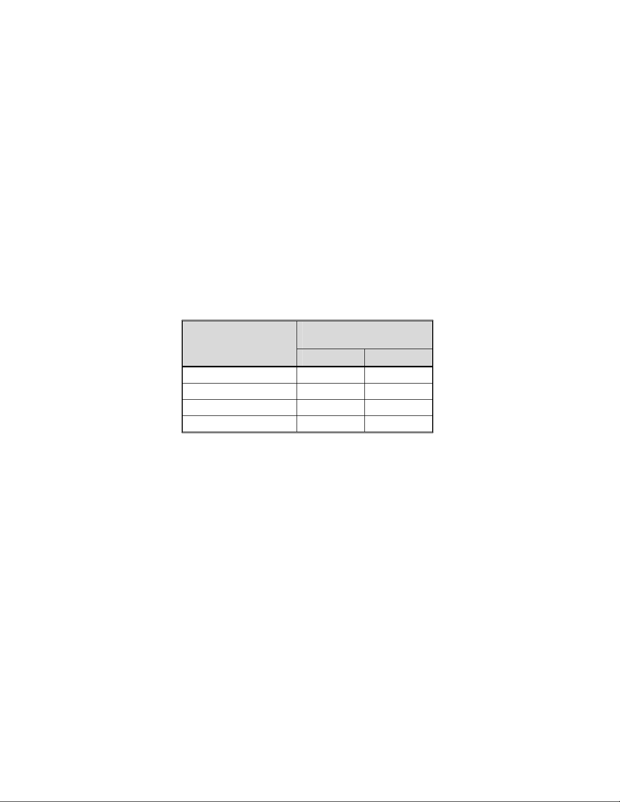
• ALWAYS keep the device and its antenna at least 2 cm (0.8 inches) from
the body and at least 5 cm (2 inches) from the face when transmitting to
ensure FCC RF exposure compliance requirements are not exceeded. This
radio has been tested for RF exposure compliance at the distances listed
in Table 1. However, to provide the recipients of your transmission the
best sound quality, hold the antenna at least 5 cm (2 inches) from mouth,
and slightly off to one side.
Table 1: RF Exposure Compliance Testing Distances
RADIO FREQUENCY
800 MHz 1.1 cm 2.5 cm
VHF (136-174 MHz) 1.1 cm 2.5 cm
UHF-H (450-512 MHz) 1.1 cm 2.5 cm
UHF-L (378-430 MHz) 1.1 cm 2.5 cm
The information in this section provides the information needed to make the
user aware of a RF exposure, and what to do to assure that this radio operates
within the FCC RF exposure limits of this radio.
TESTED DISTANCES
(worst case scenario)
Body Face
ELECTROMAGNETIC INTERFERENCE/COMPATIBILITY
During transmissions, this M/A-COM radio generates RF energy that can
possibly cause interference with other devices or systems. To avoid such
interference, turn off the radio in areas where signs are posted to do so. DO
NOT operate the transmitter in areas that are sensitive to electromagnetic
radiation such as hospitals, aircraft, and blasting sites.
6
SAFETY CONVENTIONS
The following conventions are used throughout this manual to alert the user to
general safety precautions that must be observed during all phases of
operation, service, and repair of this product. Failure to comply with these
precautions or with specific warning elsewhere in this manual violates safety
standards of design, manufacture, and intended use of the product. M/ACOM, Inc. assumes no liability for the customer’s failure to comply with these
standards.
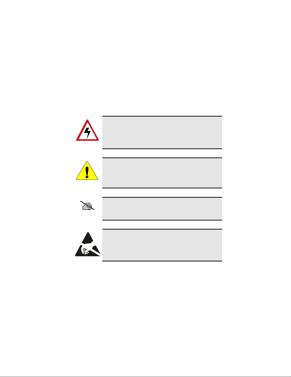
The WARNING symbol calls attention to a procedure,
practice, or the like, which, if not correctly performed or
adhered to, could result in personal injury. Do not proceed
WARNING
beyond a WARNING symbol until the conditions identified
are fully understood or met.
CAUTION
NOTE
The CAUTION symbol calls attention to an operating
procedure, practice, or the like, which, if not performed
correctly or adhered to, could result in damage to the
equipment or severely degrade the equipment performance.
The NOTE symbol calls attention to supplemental
information, which may improve system performance or
clarify a process or procedure.
The ESD symbol calls attention to procedures, practices, or
the like, which could expose equipment to the effects of
Electro-Static Discharge. Proper precautions must be taken
to prevent ESD when handling circuit modules.
7
OPERATING TIPS
Antenna location and condition are important when operating a portable rad io.
Operating the radio in low lying areas or terrain, under power lines or bridges,
inside of a vehicle or in a metal framed building can severely reduce the range
of the unit. Mountains can also reduce the range of the unit.
In areas where transmission or reception is poor, some improvement may be
obtained by ensuring that the antenna is vertical. Moving a few yards in
another direction or moving to a higher elevation may also improve
communications. Vehicular operation can be aided with the use of an
externally mounted antenna.
Battery condition is another important factor in the trouble free operation of a
portable radio. Always properly charge the batteri es.
EFFICIENT RADIO OPERATION
For optimum audio clarity at the receiving radio(s), hold the portable radio
approximately three inches from your mouth and speak into the microphone at
a normal voice level.
Keep the antenna in a vertical position when receiving or transmitting a
message.
Do not hold the antenna when receiving a message and, especially, do not
hold when transmitting a message.
Do NOT hold onto the antenna when transmitting!
WARNING
Antenna Care and Replacement
Always keep the antenna at least 0.8 inches (2 cm.) away from
the body and 2 inches (5 cm.) from the face when transmitting
to ensure FCC RF exposure compliance requirements are not
WARNING
exceeded.
Do not use the portable radio with a damaged or missing
antenna. A minor burn may result if a damaged antenna comes
into contact with the skin. Replace a damaged antenna
immediately. Operating a portable radio with the antenna
WARNING
missing could cause personal injury, damage the radio, and may
violate FCC regulations.
8
Use only the supplied or approved antenna. Unauthorized
antennas, modifications or attachments could cause damage to
the radio unit and may violate FCC regulations. (Refer to Table
WARNING
2: Options and Accessories.)
Electronic Devices
RF energy from portable radios may affect some electronic
equipment. Most modern electronic equipment in cars,
hospitals, homes, etc. are shielded from RF energy. However, in
CAUTION
areas in which you are instructed to turn off two-way radio
equipment, always observe the rules. If in doubt, turn it off!
Aircraft
Always turn off a portable radio before boarding any aircraft!
• Use it on the ground only with crew permission.
WARNING
• DO NOT use while in-flight!!
Electric Blasting Caps
To prevent accidental detonation of electric blasting caps, DO
NOT use two-way radios within 1000 feet of blasting
operations. Always obey the "Turn Off Two-Way Radios"
WARNING
signs posted where electric blasting caps are being used.
(OSHA Standard: 1926.900)
Potentially Explosive Atmospheres
Areas with potentially explosive atmosphere are often, but not
always, clearly marked. These may be fuelling areas, such as
gas stations, fuel or chemical transfer or storage facilities, and
areas where the air contains chemicals or particles, such as
grain, dust, or metal powders.
WARNING
Sparks in such areas could cause an explosion or fire resulting in
bodily injury or even death.
Turn OFF two-way radios when in any area with a potentially
explosive atmosphere. It is rare, but not impossible that a radio
or its accessories could generate sparks.
9

MARITIME CHANNELS
As part of FCC Equipment Authorization Part 80 licensing a maritime
frequency usage plan has been included in this manual for reference.
10

BATTERY DISPOSAL
The P7100IP series portable radios use rechargeable, recyclable Nickel
Cadmium (NiCd) or Nickel Metal Hydride (NiMH) batteries.
NICKEL CADMIUM BATTERY
At the end of its useful life, under various state and local
laws, it may be illegal to dispose of Nickel Cadmium
batteries into the municipal waste stream. Check with local
solid waste officials for recycling options and proper
disposal. Call Toll Free 1-800-8BATTERY for
information and/or procedures for returning rechargeable
batteries in your state.
NICKEL METAL HYDRIDE BATTERY
There are no special requirements concerning the disposal of NiMH batteries.
Batteries can be recycled. Call Toll Free 1-800-8BATTERY for information.
11

INTRODUCTION
This manual describes how to use the P7100IP series portable radio. The
IP
P7100
performance portable FM radios providing reliable two-way communications
in both the Enhanced Digital Access Communications Systems (EDACS
trunking environment and conventional communications systems.
In EDACS (trunked) mode, the user selects a communications system and
group. In this mode, channel selection is transparent to the user and is
controlled via digital communication with the system controller. This
provides advanced programmable features and fast access to communication
channels.
In the conventional mode, the user selects a channel and communicates
directly on that channel. In this mode, a system refers to a set of channels. A
channel is a transmit/receive radio frequency pair.
The exact operation of the radio will depend on the operating mode, the
radio’s programming, and the particular radio system. Most features
described in this manual can be enabled through programming. Consult the
particular features programmed into the P7100
For further detail about features and operation refer to the appropriate
maintenance manual or contact the system administrator.
WATER RESISTANCE
series radios are synthesized, microprocessor-based, high
®
)
IP
.
The P7100IP series portable radios operate reliably even under adverse
conditions. These radios meet MIL-STD-810F specifications for driven rain,
humidity, and salt fog.
12
OPTIONS AND ACCESSORIES
Table 2 lists the Options and Accessories tested for use with the P7100IP series
portable radios. Items for use with a specific band split or part number are
noted.
Refer to the maintenance manual or to M/A-COM’s Products and Services
Catalog for a complete list of options and accessories, including those items
that do not adversely affect the RF energy exposure.
Always use M/A-COM authorized accessories (antennas,
batteries, belt clips, speaker/mics, etc). Use of unauthorized
accessories may cause the FCC Occupational/Controlled
WARNING
CAUTION
Exposure RF compliance requirements to be exceeded. (Refer
to Table 2: Options and Accessories.)
Always use the correct options and accessories (battery, antenna,
speaker/mic, etc.) for the radio. Immersion rated options must
be used with an immersion rated radio. Intrinsically safe
options must be used with intrinsically safe radios. (Refer to
Table 2: Options and Accessories.)
Table 2: Options and Accessories
DESCRIPTION PART NUMBER
ANTENNAS
Antenna (136-151 MHz) KRE 101 1219/1
Antenna (150-162 MHz) KRE 101 1219/2
Antenna (162-174 MHz) KRE 101 1219/3
Antenna (378-403 MHz) KRE 101 1219/9
Antenna (403-430 MHz) KRE 101 1219/10
Antenna (378-430 MHz) KRE 101 1223/10
Antenna, Spring Whip (450-470 MHz) KRE 101 1219/12
Antenna, Spring Whip (470-512 MHz) KRE 101 1219/13
Antenna, Quarter Wave (450-512 MHz) KRE 101 1223/12
Flexible Gain Antenna (800 MHz) KRE 101 1506/1
Whip Antenna (800MHz) KRE 101 1506/2
Whip Antenna (800 MHz) KRE 101 1223/01
BATTERIES (IMMERSION-RATED)
7.5V Nickel Cadmium (NiCd) Battery BKB 191 210/33
7.5V Nickel Metal Hydride (NiMH) Battery BKB 191 210/34
7.5V NiCd Battery-Intrinsically Safe <IS> BKB 191 210/35
7.5V NiMH Battery-Intrinsically Safe <IS> BKB 191 210/36
13

DESCRIPTION PART NUMBER
BATTERIES (WIND DRIVEN RAIN)
7.5V NiCd Battery BKB 191 210/43
7.5V NiMH Battery BKB 191 210/44
MISCELLANEOUS ACCESSORIES
Speaker Mic <IS> KRY 101 1617/183
Speaker Mic Antenna Version Plus <IS> KRY 101 1617/184
Speaker Mic, Charger Compatible <IS> KRY 101 1617/185
Speaker Mic, Ant. Version, Charger Comp. <IS> KRY 101 1617/186
Speaker Mic, Immersible <IS> KRY 101 1617/283
Speaker Mic, Ant. Version, Immersible <IS> KRY 101 1617/284
Speaker Mic, Ant. Version, Immersible, Charger Comp. <IS> KRY 101 1617/287
Speaker Mic, Ruggedized <IS> KRY 101 1617/383
Speaker Mic, Antenna Version, Ruggedized KRY 101 1617/384
Speaker Mic, Ruggedized, Charger Comp., <IS> KRY 101 1617/385
Speaker Mic, Ant. Version, Ruggedized, Charger Comp <IS> KRY 101 1617/387
Metal Belt Clip KRY 101 1647/1
Belt Loop with Swivel KRY 101 1609/1
Swivel (part of KRY 101 1639 and 1648) KRY 101 1608/2
Leather Case (Belt Loop type) KRY 101 1638/1
Leather Case with Swivel & Belt Loop KRY 101 1639/1
Nylon Case (Black) with Swivel & Belt Loop KRY 101 1648/1
Nylon T-Strap KRY 101 1656/1
Earpiece Kit for Speaker Mic <IS> LS103239V1
Nylon Case (Orange) with Belt Loop KRY 101 1649/1
Swivel Mount Clip KRY 101 1608/3
Speaker Mic, Industrial OT-V2-10121
Speaker Mic, Industrial PLUS OT-V2-10122
Ultra-Lite Headset with Inline PTT OT-V4-10314
Liteweight Headset with Single Speaker OT-V4-10315
Over-the-Head Headset OT-V4-10316
Behind-the-Head Headset OT-V4-10317
Ranger Headset OT-V4-10421
Skull Microphone OT-V4-10428
Behind-the-Head Headset OT-V4-10450
Earphone Kit, Black OT-V1-10520
Earphone Kit, Beige OT-V1-10521
Earphone Kit, Black OT-V1-10522
Earphone Kit, Beige OT-V1-10523
3-Wire Mini-Lapel (Beige) OT-V1-10524
3-Wire Mini-Lapel (Black) OT-V1-10525
Throat Microphone OT-V4-10656
14

USER INTERFACE
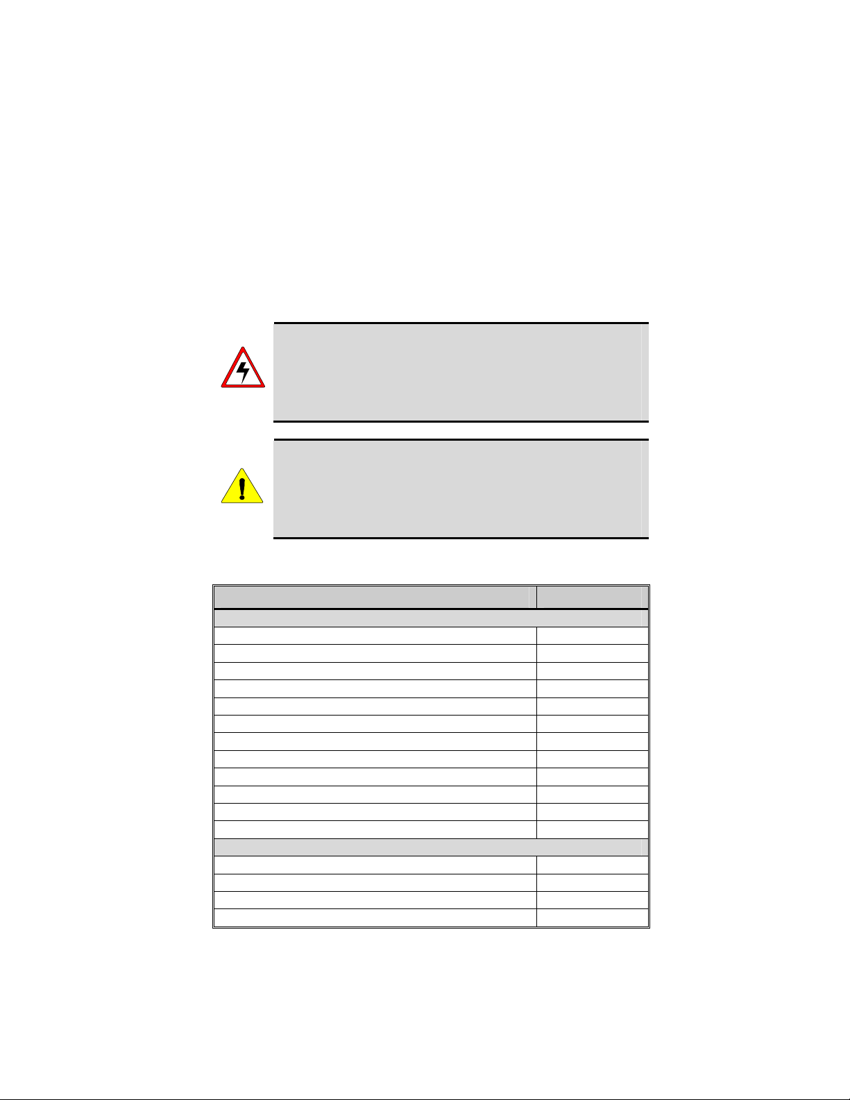
Figure 1: Top View
Figure 2: Side View
15

16
Figure 3: System Model
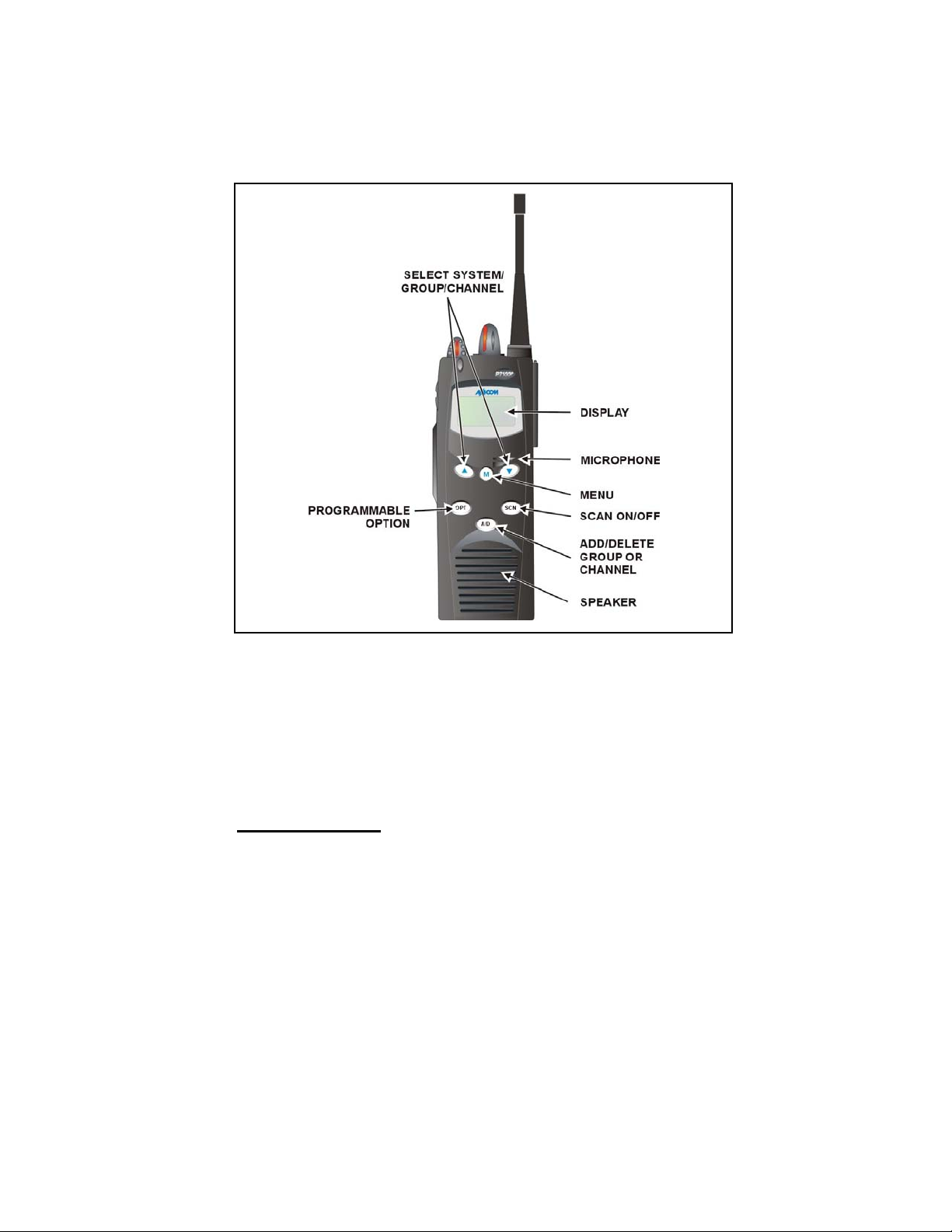
Figure 4: Scan Model
CONTROLS
The radio features two rotary control knobs and an emergency button mounted
on the top of the radio. Push-To-Talk, option and monitor buttons are
mounted on the side. The front mounted keypad has six buttons on the
IP
P7150
Buttons and Knobs
This section describes the primary function of the button and knob controls.
Other functions associated with these controls are detailed in later sections.
Scan model and 15 buttons on the P7170IP System Radio.
17

POWER ON-OFF
p
p
VOLUME KNOB
CONTROL KNOB
EMERGENCY/
HOME BUTTON
PTT BUTTON
CLEAR/MONITOR
BUTTON
OPTION BUTTON
Applies power to and adjusts the receiver’s volume. Rotating
the control clockwise applies power to the radio. A single alert
tone (if enabled through programming) indicates the radio is
operational.
Rotating the control clockwise increases the volume level.
Minimum volume levels may be programmed into the radio to
prevent missed calls due to a low volume setting. While
adjusting the volume the display will momentarily indicate the
volume level (i.e. VOL=31). The volume range is from a
minimum programmed level of zero (displayed as OFF in the
display) up to 31, which is the loudest level.
Selects systems or group/channels (depending on programming).
This is a 16-position rotary knob.
Note: A mechanical stop, which can limit the positions
accessed, is shipped with the radio but must be installed. To
install the mechanical stop, remove the channel knob, loosen the
set screw on the channel knob metal base (using a 1.27mm hex
wrench), and remove the channel knob metal base. Replace the
16 channel ring with the channel stop ring located at the desired
channel. Reinstall the channel knob metal base, tighten the set
screw, and reinstall the channel knob.
Automatically selects the pre-programmed Group/System by
ressing and holding for a programmed duration. It can also be
used to declare an emergency by pressing and holding for a
programmed duration. The button must be preeither operation, but not both.
Push-To-Talk must be pressed before voice transmission begins.
In trunked mode the radio’s ID is transmitted upon depression of
the PTT button. (Refer to Figure 2 for location.)
In trunked mode: Exits the current operation (removing all
displays associated with it) and returns the radio to the selected
talk group. Terminates individual and telephone interconnect
calls.
In conventional mode: Unsquelch the receiver and allows
channel monitoring prior to transmission. Momentarily removes
the Channel Guard decoding from the channel.
Activates one of a number of programmable software options
selected during PC programming. Programmable options
include hi/low power settings, keypad lock, LCD contrast, LCD
and keypad back lighting.
rogrammed for
Keypad
The keys on the Keypad have special functions and are labeled using a symbol
or abbreviated word describing its primary function. Numeric entry is a
secondary function of the keys. Each key is described in the following
subsections.
18
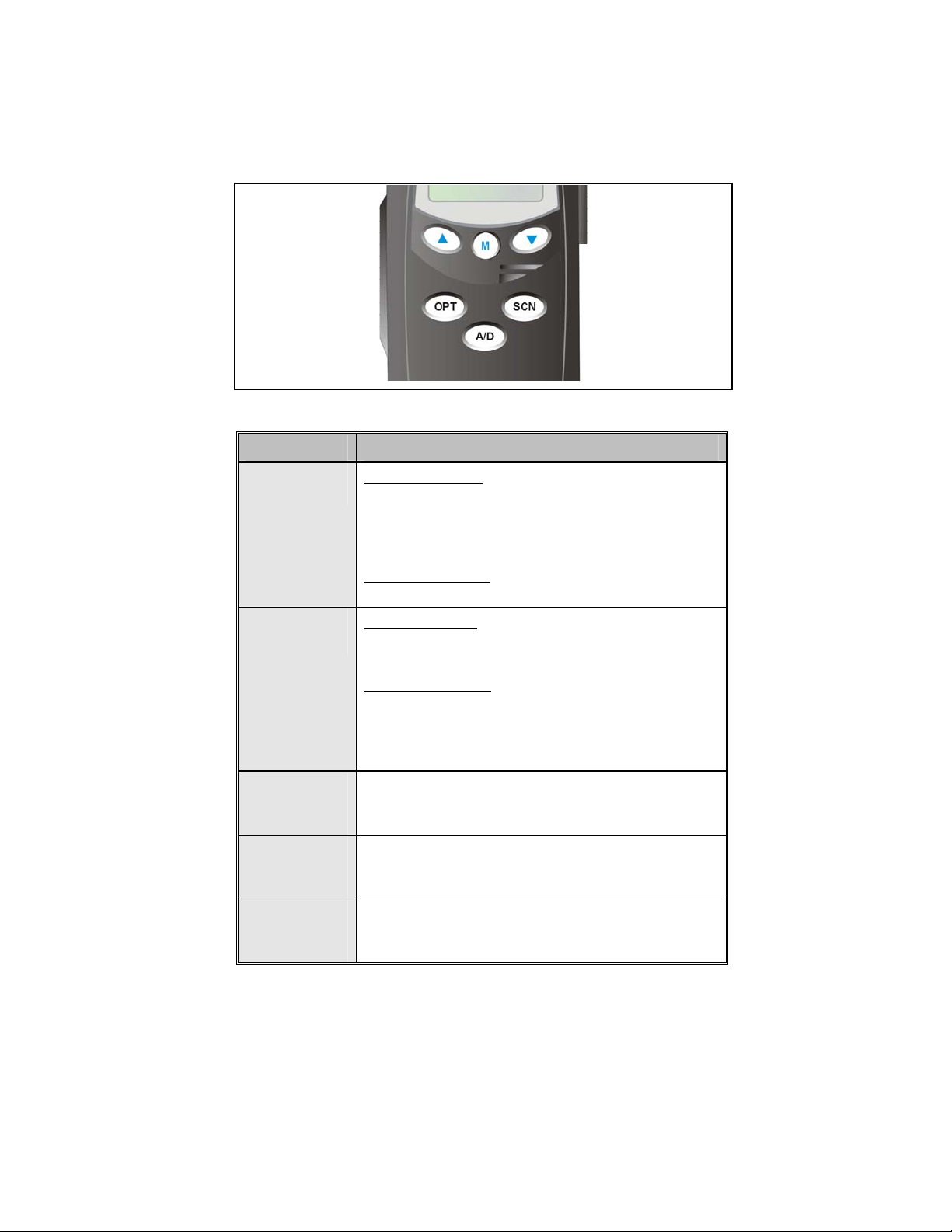
Figure 5: Scan Radio Front Panel
KEY FUNCTION
Primary Function: Allows the user to select system,
groups, or channels, depending on personality
programming. The buttons act as STEP UP or STEP
DOWN. Pressing one of these buttons displays the next
or previous stored system, group or channel.
(Scan only)
(Scan only)
(Scan only)
Secondary Function
within a list.
Primary Function: Accesses the pre-stored menu. The
menu can include high/low power setting, keypad lock,
LCD contrast, LCD and keypad backlighting.
Secondary Function
list. After a menu list is accessed, scroll through the list
using the
items with the
Adds/Deletes selected groups or channels from the Scan
list of the currently selected system.
Turns the Scan operation ON and OFF.
Activates one of a number of programmable software
options.
or keys and then activate specific
: Changes the selection for an item
: Activates a selected item within a
key. This is similar to an “Enter” key.
19
Figure 6: System Radio Front Panel
KEY FUNCTION
1-9, *, 0, #
Same as Scan Model
Same as Scan Model
Selects a specific system. If the rotary knob is used to
select the system and more than 16 systems are
programmed in the radio, the
additional banks (groupings) of systems.
These keys are used to place telephone interconnect and
individual (unit-to-unit) calls. The keys operate like a
normal telephone keypad.
Selects a specific group.
Turns the Scan operation ON and OFF.
Enables or disables Private Mode for the
system/group/channel displayed.
Adds groups or channels from the currently selected
system to the Scan list.
Status. Access to the status list (0-9). The Status key
permits the transmission of a pre-programmed status
message to an EDACS site.
key is used to select
20
Message. Access to the message list (0-9). The
Message key permits the transmission of a preprogrammed message to an EDACS site.
continued
 Loading...