

HARRIS TR-0012-E Motorcycle manual

Installation Manual
MM101013V1 R1A
J
AGUAR
TM
725M
MOBILE RADIO &
CONTROL UNIT
MOTORCYCLE INSTALLATION

NOTICE
Repairs to this equipment should be made only by an authorized service
technician or at a facility designated by the supplier. Any repairs, alterations
or substitutions of recommended parts made by the user to this equipment
not approved by the manufacturer could void the user’s authority to operate
the equipment in addition to the manufacturers warranty.
NOTICE
The software contained in this device is copyrighted by M/A-COM
Private Radio Systems, Inc. Unpublished rights are reserved under the
copyright laws of the United States.
This manual is published by
Improvements and changes to this manual necessitated by typographical errors, inaccuracies of
current information, or improvements to programs and/or equipment, may be made by
COM Private Radio Systems, Inc.
incorporated into new editions of this manual. No part of this manual may be reproduced or
transmitted in any form or by any means,. electronic or mechanical, including photocopying
and recording, for any purpose, without the express written permission of
Radio Systems, Inc.
Copyright 2001 M/A-COM Private Radio Systems, Inc. All rights reserved.
M/A-COM Private Radio Sy stems, Inc.
, at any time and without notice. Such changes will be
, without any warranty.
M/A-
M/A-COM Private
2

Table of Contents
SAFETY TRAINING INFORMATION.........................................................4
TRANSMITTER HAZARDS........................................................................5
SAFE DRIVING RECOMMENDATIONS...................................................6
GENERAL INFORMATION..........................................................................8
RELATED DOCUMENTATION..................................................................8
OPTIONS AND ACCESSORIES....................................................................9
VENDOR DROP SHIP OPTIONS................................................................9
External Headset Options..........................................................................9
HARDWARE KITS.....................................................................................10
USER SUPPLIED EQUIPMENT................................................................14
POWER CONSIDERATIONS....................................................................14
RF Power Adjustments...........................................................................14
INSTALLATION............................................................................................17
TOOLS REQUIRED...................................................................................17
EQUIPMENT INSTALLATION.................................................................17
Assembling & Installing the Weather Resistant Case Assembly.............17
Harley-Davidson Installation ..................................................................19
RADIO MOUNTING BRACKETS............................................................. 1 9
CONTROL UNIT MOUNTING...................................................................22
Control Unit And Mic Hanger Installation..............................................22
SPEAKER MOUNTING.............................................................................23
CABLE ROUTING......................................................................................26
Power and Control Cables.......................................................................26
Option Cable...........................................................................................26
Typical Harley-Davidson Installation.....................................................27
CABLE CONNECTIONS ...........................................................................31
Power Cable............................................................................................31
Control Cable..........................................................................................31
Ignition Switch Option............................................................................32
Accessory Cable......................................................................................32
ANTENNA INSTALLATION.....................................................................32
General....................................................................................................32
Typical Motorcycle Mount Antenna Installation....................................34
FINAL CHECKS AND CONNECTIONS....................................................35
HEADSET INSTALLATION (OPTION)....................................................35
Headset Operation...................................................................................36
3
SAFETY TRAINING INFORMATION
Your M/A-COM J
RF electromagnetic energy during transmit mode. This radio
is designed for and classified as “Occupational Use Only,”
meaning it must be used only during the course of
WARNING
This radio has been tested and complies with the FCC RF exposure limits
for “Occupational Use Only.” In addition, your M/A-COM radio complies
with the following Standards an d Guidelines with regard to RF energy and
electromagnetic energy levels and evaluation of such levels for exposure to
humans:
FCC OET Bulletin 65 Edition 97-01 Supplement C, Evaluating
•
Compliance with FCC Guidelines for Human Exposure to Radio
Frequency Electromagnetic Fields.
American National Standards Institute (C95.1-1992), IEEE Standard
•
for Safety Levels with Respect to Human Exposure to Radio Frequency
Electromagnetic Fields, 3 kHz to 300 GHz.
American National Standards Institute (C95.3-1992), IEEE
•
Recommended Practice for the Measurement of Potentially Hazardous
Electromagnetic Fields – RF and Microwave.
employment by individuals aware of the hazards and the
ways t o minimize such hazards. This radio is not intended
for use by the “General Population” in an uncontrolled
environment.
AGUAR
™ 725M Mobile Radio generates
To ensure that your exposure to RF electromagnetic energy
is within the FCC allowable limits for occupational use,
always adhere to the following guidelines:
CAUTION
DO NOT operate the radio without a proper antenna attached, as this
•
may damage the radio and may also cause you to exceed FCC RF
exposure limits. A proper antenna is the antenna supplied with this
radio by M/A-COM or an antenna specifically authorized by M/ACOM for use with this radio.
4
•
DO NOT transmit for more than 50% of total radio use time (50% duty
cycle). Transmitting more than 50% of the time can cause FCC RF
exposure compliance requirements to be exceeded. The radio is
transmitting when the “TX” LED in the radio display is lit. You can
cause the radio to transmit by pressing the PTT button on the
microphone.
•
ALWAYS use M/A-COM authorized accessories (antennas,
speaker/mics, etc.). Use of unauthorized accessories may cause the FCC
Occupational/Controlled Exposure RF compliance to be exceeded.
•
ALWAYS keep at least 20 cm (8 inches) between the antenna and
operator/bystanders while transmitting. This radio has been tested and
found compliant with Specific Absorption Rate (SAR) limits for
uncontrolled exposure at a distance of 20 cm (8 inches) or more using a
50% duty cycle.
The information listed above is provided to make the user aware of an
RF exposure and what to do to assure that this radio operates within
the FCC RF exposure limits of this radio.
TRANSMITTER HAZARDS
The operator of any mobile radio should be aware of certain
hazards common to the operation of vehicular radio
transmitters.
A list of several possible hazards is given:
WARNING
Explosive Atmospheres –
•
the motor running, similar hazards exist when operating a mobile radio.
Be sure to turn the radio off while fueling a vehicle. Do not carry
containers of fuel in the trunk of a vehicle if the radio is mounted in the
trunk.
Areas with potentially explosive atmosphere are often, but not
always, clearly marked. Turn OFF your radio when in any area
with a potentially explosive atmosphere. It is rare, but not
impossible that the radio or its accessories could generate sparks.
Interference to Vehicular Electronics Systems –
•
injection systems, electronic anti-skid braking systems, electronic
cruise control systems, etc., are typical electronic systems that may
malfunction due to the lack of protection from radio frequency energy
Just as it is dangerous to fuel a vehicle with
Electronic fuel
5

present when transmitting. If the vehicle contains such equipment,
consult the dealer and enlist their aid in determining the expected
performance of electronic circu its when the radio is transmitting.
•
Dynamite Blasting Caps –
Dynamite blasting caps may explode by
operating a radio within 500 feet of the blasting caps. Always obey the
Turn Off Two-Way Radios
“
” signs posted where dynamite is being
used.
•
When transporting blasting caps in your vehicle:
¾
Carry the blasting caps in a closed metal box with a soft lining.
¾
Leave the radio
whenever the blasting caps are being put into
OFF
or removed from the vehicle.
•
Liquefied Petroleum (LP) Gas Powered Vehicles –
Mobile radio
installations in vehicles powered by liquefied petroleum gas with the
LP gas container in the trunk or other sealed-off space within the
interior of the vehicle must conform to the National Fire Protection
A
ssociation standard
¾
The space containing the radio equipment shall be isolated by a
NFPA 58
requiring:
seal from the space containing the LP gas container and its fittings.
¾
Outside filling connections shall be used for the LP gas container.
¾
The LP gas container shall be vented to the outside of the vehicle.
SAFE DRIVING RECOMMENDATIONS
(Recommended by AAA)
•
Read the literature on the safe opera tion of the radio.
•
Keep both hands on the steering wheel and the microphone in its
hanger whenever the vehicle is in motion.
•
Place calls only when the vehicle is stopped.
•
When talking from a moving vehicle is unavoidable, drive in the
slower lane. Keep conversations brief.
•
If a conversation requires taking notes or complex thought, stop the
vehicle in a safe place and continue the call.
•
Whenever using a mobile radio, exercise caution.
6
Figure 1 – Typical J
AGUAR
725M Motorcycle Installation
7

GENERAL INFORMATION
This manual contains instructions for installing the J
AGUAR
radio, J
The instructions in this manual are typical installation instructions, and are
not intended to cover all makes and models of motorcycles.
Final installation of the radio equipment is left to the discretion of the radio
installer.
To simplify installation and minimize difficulties, it is suggested that the
installer read the entire manual prior to installation. Figure 1 shows a
typical motorcycle installation.
725M control unit, and associated hardware on a motorcycle.
M/A-COM Private Radio Systems, Inc. does not assume
liability for possible degradation of the radio or motorcycle
performance due to mounting procedures.
AGUAR
725M mobile
NOTE
RELATED DOCUMENTATION
AGUAR
J
725M Mobile Radio Operator’s Manual,
Scan & System (800 MHz)......................................MM101258V1
8

OPTIONS AND ACCESSORIES
All available options and accessories applicable to factory installed
motorcycle installations are defined below. NOTE: These options do not
AGUAR
include a J
725M radio or J
725M mobile radio and control unit must be ordered separately, then factory
modified to adapt it for motorcycle applications. Applicable hardware is
included with each option.
AGUAR
725M control unit. The J
AGUAR
HBxxxx J
HBxxxx J
HBxxxx Field upgrade kit to adap t existing remote mount J
AGUAR
725M Mobile Radio with Scan Control Unit
AGUAR
725M Mobile Radio with System Control Unit
AGUAR
725M radios for motorcycle applications
VENDOR DROP SHIP OPTIONS
The following is a listing of all available Vendor drop-ship options.
External Headset Options
SM-K71BP Helmet Kit: Bell BT400 with speaker and noise
canceling microphone
SM-74KBP Helmet Kit: Bell BT400 with dual speakers and noise
canceling microphone (see NOTE on page 36)
SM-K71QA Helmet Kit: SHOE1 TJ101 with speaker and noise
canceling microphone
SM-K74QA Helmet Kit: SHOE1 TJ101 with dual speakers and
noise canceling microphone (see NOTE on page 36)
SM-MCH-71GT-2 Helmet Kit Interface Cable (pushbutton switch with
PTT function; interfaces with K71BP/K74BP/
K71QA/K74QA helmet kits; Harley-Davidson)
SM-MCH-72GT-2 Helmet Kit Interface Cable (rocker switch with PTT
and CG decode disable functions; interfaces with
K71BP/K74BP/ K71QA/K74QA helmet kits; HarleyDavidson); or
SM-C70GM Belt Box Cable Assembly Interface.
9

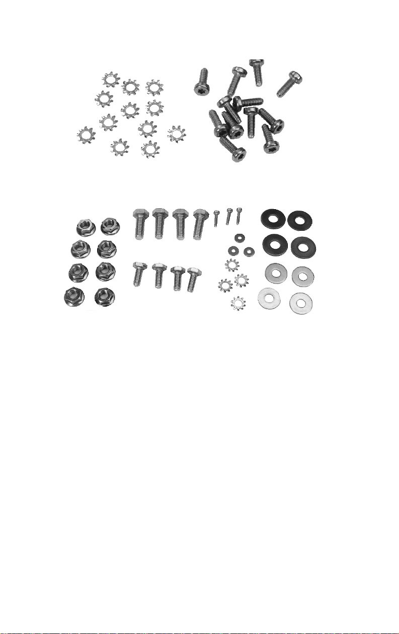
HARDWARE KITS
A typical Motorcycle Kit is shown in Figure 2. Hardware Kits
350A1396G1-G4 are shown in Figure 3 and Figure 4. Hardware kit
350A1396G1 is used to factory install the radio mounting bracket and
alternator whine reject filter to the weather-resistant case. Hardware kits
350A1396G2-G4 are used by the customer in the field to mount the case
and control head to the motorcycle and to optionally use the HarleyDavidson adapter bracket. The Motorcycle Kit includes the items listed
below. The antenna and Helmet Kit are optional.
•
MIL-STD weather resistant locking J
integral antenna ground plane
•
Radio case mounting plate kit
•
MIL-STD weatherproof microphone
•
Microphone hangar
•
MIL-STD weatherproof speaker
•
Power/Control Cable
•
Fuse Kit
•
Motorcycle accessory cable
AGUAR
725M radio case with
10
Figure 2 - Typical Motorcycle Kit
11
Hardware Application Kit 350A1396G1
Case/Antenna Assembly Hardware Kit 350A1396G2
Figure 3 - Hardware Installation Kits For Harley-Davidson
Motorcycles
12
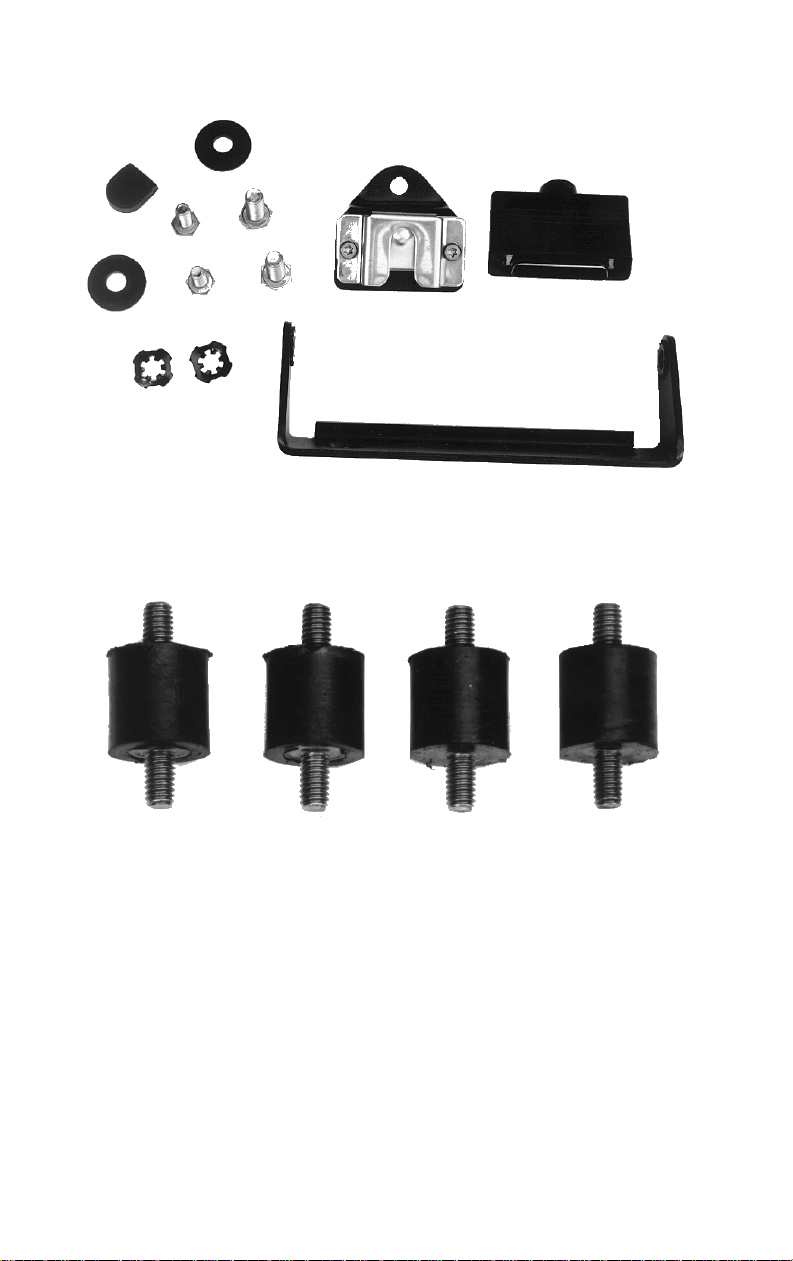
Control Unit/Microphone Hardware Kit 350A1396G3
Motorcycle Adapter Mounting Kit 350A1396G4
Figure 4 - Typical Hardware Installation Kits For Harley-Davidson &
Kawasaki Motorcycles
13
USER SUPPLIED EQUIPMENT
•
Motorcycle Radio Mounting Bracket
POWER CONSIDERATIONS
The motorcycle may be equipped with additional lights, light flashers,
sirens, PA systems, etc. Therefore, consideration must be given to the total
system current drain. It is recommended that the radios be set to not exceed
the applicable rated RF power output and current drain shown in Table 1 for
AGUAR
all J
725M motorcycle applications.
Do NOT
use a J
725M mobile radio with power
AGUAR
exceeding the power limits shown in Table 1 for motorcycle
applications. To do so will result in damage to the
CAUTION
motorcycle alternator, battery, and all circuits. Also, the
possibility of interference is increased if the proper RF
power level is not used. As a final note, RF power may not
be set to exceed the maximum regulatory RF power
specified by that country’s regulatory agency.
RF Power Adjustments
For factory installed options the maximum RF power levels are factory
preset and should only require verification in the field. See Table 1.
For field installed options, the RF power of previously purchased J
AGUAR
725M mobile radios in the field must be appropriately set via modification
of the maximum RF power tracking data fields. The left column is set for
rated power (example: 250 for 25.0 watts). The tracking data numbers are
adjusted to produce RF power as specified in the actual “J
AGUAR
725M
Motorcycle Radio RF Power” column in Table 1.
High power J
725M mobile radios
AGUAR
CANNOT
be
used in motorcycle applications. The RF power cannot be
turned down sufficiently to meet regulatory specifications.
NOTE
14

RF Power Tracking Data for Resetting in the Field
800 MHz Band:
•
6-12 watts, low power J
AGUAR
725M: no resetting of RF power
tracking data is needed.
•
17.5-35 watts, high power J
AGUAR
725M (repeater input band 806-825
MHz): RF power tracking data is reset as follows:
1. The RF Power tracking data shown in the “350” row under the “TX
Power Levels” columns must be adjusted down to 27 ± 0.5 watts.
This same tracking data should be copied into the “300” row under
the “TX Power Levels” columns.
2. This will set the upper limit of the 800 MHz mobile in the repeater
input band to a rated RF power of 25 watts (with an actual RF
power setting level of 27 ± 0.5 watts).
The 800 MHz RF power tracking data settings are listed in MM101260V1
under the sections for TRACKING DATA, TEST FREQUENCIES, &
SETTING TRACKING DATA. Tracking data frequencies are listed in
Table 2 in the TX RPT INPUT column.
•
15-30 watts, high power J
AGUAR
725M (repeater talkaround band 851-
870 MHz): RF power tracking data is reset as follows:
1. The RF Power tracking data shown in the “30” row under the “TA
TX Power Levels” columns must be adjusted down to 27 ± 0.5
watts. This same tracking data should be copied into the “35” row
under the “TA TX Power Levels” columns.
2. Change the “30” & “35” row labels to “25”.
3. This will set the upper limit of the 800 MHz mobile in the repeater
talkaround band to a rated RF power of 25 watts (with an actual RF
power setting level of 27 ± 0.5 watts).
The 800 MHz RF power tracking data settings are listed in MM101260V1
under the sections for TRACKING DATA, TEST FREQUENCIES, &
SETTING TRACKING DATA. Tracking data frequencies are listed in
Table 2 in the TX TALK AROUND column.
15
 Loading...