

HARRIS TR-0005-A Users Manual
MM101031V1 R1A
Installation Manual
P
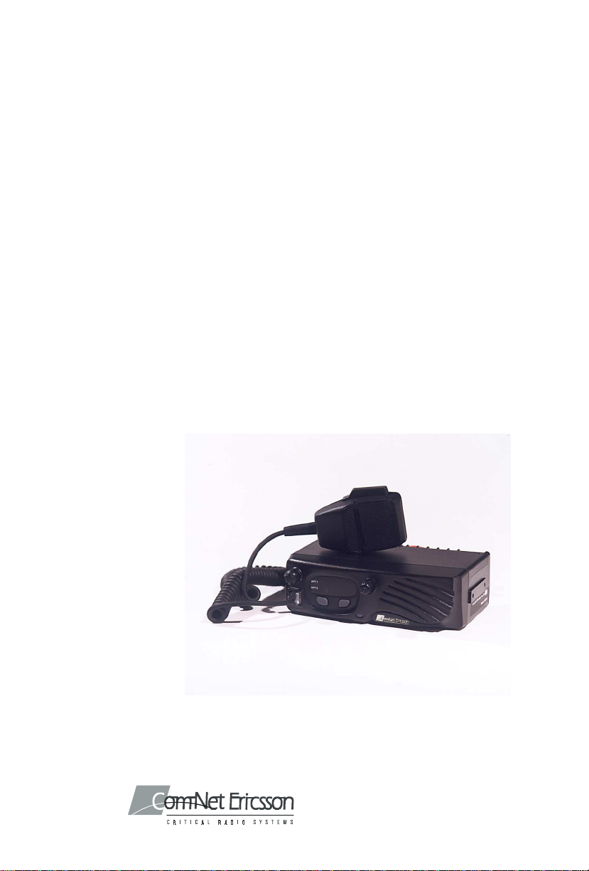
ANTHER
TM
300M
Mobile Radio

NOTICE!
Repairs made to this equipment should be made only by an authorized
service technician or facility designated by the supplier. Any repairs,
alterations, or substitution of recommended parts made by the user to this
equipment not approved by the manufacturer could void the user’s
authority to operate the equipment in addition to the manufacturer’s
warranty.
NOTICE!
The software contained in this device is copyrighted by Com-Net Ericsson
Critical Radio Systems, Inc. Unpublished rights are reserved under the
copyright laws of the United States.
This manual is pub lished by Com-Net Ericsson Critical Radio Systems, Inc., without any
warranty. Improvements and changes to this manual necessitated by typographical errors,
inaccuracies of current informati on, or improvements t o programs and/or equip ment, may be
made by Com-Net Ericsson Critical Radio Systems, Inc., at any time and without noti ce.
Such changes will be in corporated into new edi tions of this manual. No part of this manual
may be reproduc ed or transmitted in any form or b y any means, electron ic or mechanical,
including photocopying and recording, for any purpose, without the express written permission
of Com-Net Ericsson Critical Radio Systems, Inc.
Copyright © 2000, Com-Net Ericsson Critical Radio Systems, Inc. All rights reserved.
2

TABLE OF CONTENTS
SAFETY INFORMATION.....................................................................................4
MAXIMUM PERMISSIBLE EXPOSURE (MPE) LIMITS................................5
DETERMINING MPE RADIUS.......................................................................5
SAFETY TRAINING INFORMATION................................................................6
INTRODUCTION....................................................................................................8
UNPACK AND CHECK THE EQUIPMENT.......................................................8
OPTIONS AND ACCESSORIES......................................................................9
INSTALLATION...................................................................................................10
STEP 1 - PLAN THE INSTALLATION .........................................................10
STEP 2 - LOCATE THE TOOLS REQUIRED...............................................10
STEP 3 – EQUIPMENT PREPARATION ......................................................11
Mounting..................................................................................................11
STEP 4 – PROGRAM THE RADIO................................................................16
STEP 5 – INSTALL CABLES .........................................................................17
Power Cable.............................................................................................17
Connect To Ignition Sense .......................................................................18
Radio Mounting Procedures.....................................................................20
STEP 7 – INSTALL OPTIONS AND ACCESSORIES ..................................22
Radio Option Cable..................................................................................22
External Speaker – 19A149590P11..........................................................25
Alarm (Horn) Relay Kit - 19A705499P1 .................................................28
Microphone Hanger/Hook Switch Mounting – 344A4678P1...................30
Antenna....................................................................................................30
Noise Suppression Kit - Option KMPD1A (19A148539G1)....................32
FIGURES
Figure 1 – Typical Connection Diagram..................................................................12
Figure 2 – Removing Top Cover..............................................................................13
Figure 3 – Factory Default Internal Speaker Jumper Setting (Enabled)................... 14
Figure 4 – Factory Default Settings For Jumper JP600 ............................................15
Figure 5 – Removing Plastic Cover..........................................................................16
Figure 6 – Power Cable RPM 113 7674/10..............................................................18
Figure 7 – Mounting Bracket and Mounting Bracket Hardware Kit........................20
Figure 8 –Mounting Bracket Installation..................................................................21
Figure 9 – Mounting Radio to Bracket.....................................................................22
Figure 10 - Mounting the External Speaker.............................................................25
Figure 11 – External Speaker Option....................................................................... 26
Figure 12 – Internal/External Speaker Relay............................................................27
Figure 13 - External Car Alert..................................................................................29
Figure 14 - External Alarm Relay............................................................................29
Figure 15 – Ignition Sense Option............................................................................30
TABLES
Table 1 - P
Table 2 – Radio Option Connector P3 Interface Description...................................23
300M Mobile Radio Options and Accessories............................9
ANTHER
3

SAFETY INFORMATION
The operator of any mobile radio should be aware of certain hazards
common to the operation of vehicular radio transmissions.
several possible hazards is given:
1. Explosive Atmospheres - Just as it is dangerous to fuel a vehicle with
the motor running, similar hazards exist when operating a mobile radio,
be sure to turn the radio off while fueling the vehicle. Do not carry
containers of fuel in the trunk of the vehicle if the radio is mounted in
the trunk.
2. Interference to Vehicular Electronics Systems - Electronic fuel
injection systems, electronic anti-skid braking systems, electronic
cruise control systems, etc., are typical electronic systems that may
malfunction due to the lack of protection from radio frequency energy
present when transmitting. If the vehicle contains such equipment,
consult the dealer and enlist their aid in determining the expected
performance of electronic circuits when the radio is transmitting.
3. Dynamite Blasting Caps - Dynamite blasting caps may be caused to
explode by operating a radio within 500 feet of the blasting caps.
Always obey the "Turn Off Two-Way Radios" signs posted where
dynamite is being used.
When transporting blasting caps in your vehicle:
a. Carry the blasting caps in a closed metal box with a soft lining.
A list of
b. Leave the radio OFF whenever the blasting caps are being put into
or removed from the vehicle.
4. Liquefied Petroleum (LP) Gas Powered Vehicles - Mobile radio
installations in vehicles powered by liquefied petroleum gas with the
LP gas container in the trunk or other sealed-off space within the
interior of the vehicle must conform to the National Fire Protection
Association standard (NFPA) 58 requiring:
a. The space containing the radio equipment shall be isolated by a
seal from the space containing the LP gas container and its fittings.
b. Outside filling connections shall be used for the LP gas container.
c. The LP gas container shall be vented to the outside of the vehicle.
4

MAXIMUM PERMISSIBLE EXPOSURE (MPE)
LIMITS
Do not transmit with this radio and antenna when persons are within the
MPE Radius of the antenna, unless such persons (such as the driver or radio
operator) are shielded from the antenna field by a grounded metallic barrier
(such as the user’s vehicle rooftop). The MPE Radius is the minimum
distance from the antenna axis that persons should maintain in order to
avoid RF exposure higher than the allowable MPE level set by the FCC.
FAILURE TO OBSERVE THESE LIMITS
MAY ALLOW THOSE WITHIN THE MPE
RADIUS TO EXPERIENCE RF RADIATION
ABSORPTION WHICH EXCEEDS THE FCC
WARNING
EXPOSURE LIMITS ARE OBSERVED AT ALL TIMES
DURING RADIO TRANSMISSION. THE RADIO
OPERATOR IS TO ENSURE THAT NO BYSTANDERS
COME WITHIN THE RADIUS OF THE MAXIMUM
PERMISSIBLE EXPOSURE LIMITS SHOWN BELOW.
MAXIMUM PERMISSIBLE EXPOSURE
(MPE) LIMIT. IT IS TH E RESPONS IBILITY
OF THE RADIO OPERATOR TO ENSURE
THAT THE MAXIMUM PERMISSIBLE
DETERMINING MPE RADIUS
THE MAXIMUM PERMISSIBLE EXPOSURE RADIUS HAS
BEEN ESTIMATED TO BE A RADIUS OF ABOUT 55
INCHES (OR 138 CM) FOR THE VEHICULAR MOUNTED
ANTENNA SYSTEMS, AND 77 INCHES (OR 195 CM) FOR
BASE STATION MOUNTED ANTENNA SYSTEMS PER OET
BULLETIN 65 OF THE FCC. THIS ESTIMATE IS MADE
ASSUMING THE MAXIMUM CAPABLE POWER OF THE
RADIOIS TRANSMITTED AND ANTENNAS WITH A
MAXIMUM GAINS OF 3 dBd ARE USED FOR VEHICULAR
MOUNTED SYSTEMS AND 6 dBd FOR BASE STATION
SYSTEMS.
A MAXIMUM 50% TRANSMIT DUTY CYCLE IS ASSUMED,
DUE TO THE PUSH-TO-TALK STATUS FO THIS MOBILE.
5
 Loading...