

Harris STL-160, ACS-160, ACS-163, ACS-165, ACS-166 Installation & Operation Manual
...
Intraplex
®
ACS-160 & STL-160 Series T1 Multiplexer
Installation & Operation Manual
ACS-163 Terminal Access Server (3RU)
ACS-165 Drop & Insert Access Server ( 3R U)
ACS-166 Dual Terminal Access Serv er ( 3R U )
ACS-167 Terminal Access Server (1RU)
ACS-168 Drop & Insert Access Server ( 1RU)
ACS-169 Dual Terminal Access Server (1RU)
STL-163 Studio-to-Transmitter Link (3RU)
STL-165 Studio-to-Transmitter Link (3RU)
STL-166 Studio-to-Transmitter Link (3RU)
CM-5RB Common Module
CM-5R-TD Time Delay Common Module
TOTAL CONTENT DELIVERY SOLUTIONS | Managing content. Delivering results.
Version 2.11

Intraplex® T1 Multiplexer
Reproduction, adaptation, or translation without
herein or for inc ide ntal or consequential damage
If you have a technical question or issue with your Intr a p lex
Installation an d Operation Manual
Version 2.11, August 2011
© Copyright 2000, 2010, and 2011
Harris Corporation. All rights reserved.
prior written permission is prohibited, except as
allowed under the c opyright laws.
Warranty
The information c ontained in this document is
subject to change without notice. Harris makes
no warranty of a ny kind with regard to this
material, including, but not limited to, the
implied warrantie s of merchantability and
fitness for a particular purpose.
Harris shall not b e liable for errors contained
in connection w ith the furnishing, performance,
or use of this mater ial.
Trademark Credits
®
Harris
IntraGuide
, AudioLink PLUS™, HD Link™,
®
, Intraplex®, NetXpress™,
NetXpress LX™, STL PLUS®, SynchroCast® and
SynchroCast3™ are trademarks of Harris
Corporation. Other trademarks are the property
of their respective owners .
Version Date Revisions Made Section Pages Editor
2.11 8/8/2011 Removed sentence in first paragraph of Power Supp ly Mo d ules
2.1 4/29/2011 Added height to 3RU and 1RU references in introductio n. 1.3 1-2 LD
section regarding DC power supply. Added a note below paragraph
to explain combined AC and DC power supply operatio n. Adde d
another note to section to explain function of power supply
redundancy.
Reversed labels for Pin 1 and Pin 2 for RJ connector on Tables 3-4,
3-5, and 3-11 (now Table 3-9). Removed Tables 3-8 and 3-9, as
they were the same as Tables 3-4 and 3-5. Switched RJ connector
Pin 1 and Pin 2 on Figure 3-31.
Updated information for Power Supplie s . 1.4 1-4
Added replaceable battery warning to end of Microp ro c ess or Control
and Battery-Backed Memory section.
Updated Power Supply Modules informatio n. 2.1.5 2-18
Reworded warning at end of Module Adapters section. 2.1.7 2-22
Added height to Multiplexer Shelf Ins tallati o n g ui d e line s . 3.3 3-2
Removed RING GEN from Figures 3-3, 3-10, 3-16 – 3-19 and Table
3-16, as the purpose of this connection has changed.
Updated Table 3.17 Nominal Power Require ments for Co mmon
Modules and Module Adapters and warning. Reworded paragraph
following warning.
Corrected voltage for Power Supply Test. 6.6.4 6-20
How to Contact Us
Harris Corporation
Intraplex Produ c ts
5300 Kings Island Drive, Ste. 101
Mason, OH 45040
USA
Sales: +1 513 459 3400
Fax: +1 513 701 5316
E-mail:
intraplex@harris.com
Web: www.broadcast.harris.com
How to Get Support
Products equipment, pleas e c heck our Customer Support
Web page:
www.broadcast.harris.com/support/productsupport.asp
You can also call the Customer Support line or send
non-emergency e-mail:
● U.S., Canada, and Latin America: +1-217-222-8200 or
tsupport@harris.com
● Europe, Middle East, an d Africa: +44-118-967-8100 or
Service.europe@harris.com
● Asia and Pacific Rim: +852-2776-0628 or
BCDService@harris.com
2.1.5 2-18 LD
3.5.2
3.6.2.3
2.1.3.6 2-6
3.4.2
3.6
3.6.5
3.6.6 3-22
3-8
3-10 – 3-11
3-13
3-14
3-4
3-12
3-18 – 3-20

Version Date Revisions Made Section Pages Editor
2.1
(cont.)
2.02 10/1/2010 Combined Wiring and Power sections into Wiring & Power section. 3.6 – 3.7 3-12 – 3-23 LD
2.01 6/16/2010 Corrected the model list on cover, changing “ACS-160” to
4/29/2011 Correcte d Spe c s : Consump tion, PS Y5024 and PSY100AC Output
Power, and 1RU Shelf Output Power. Added Regulatory
Compliance.
Added Available Power subsection. 3.6.6 3-22
Renamed C hanne l Mo dule Addition to Existing Systems to Channel
Module Installation subsec tio n. Adde d S he lf Power for Add itional
Channel Modules subsection and renumbered other subsections as
needed.
“ACS-169” and adding ACS-168 model.
Made global correction in Section 2, changing “backplane” to
“midplane” in all locations.
Added note to Sections 1 and 2 regarding inability to co nvert most
models into other models. Listed models that could be converted.
2 4/23/2010 Converted entire manua l into Word , p la ced in new temp l ate,
reformatted, and updated for line redund ancy and power s upp lie s .
7.1 7-4
3.7 3-23 – 3-24
Cover Cover LD
2 2-1 – 2-29
1.3
2.2.1
All All LD
7-5
1-2
2-1
LD

This page is left blank intentionally.

No header here
Table of Contents
Section 1 – Introduction ................................................................ 1-1
1.1 Manual Scope ................................................................................... 1-1
1.2 Manual Use ...................................................................................... 1-2
1.3 Multiplexer Configurations .................................................................. 1-2
1.4 Multiplexer Component Parts .............................................................. 1-3
1.4.1 Main Equipment Shelf ............................................................................1-3
1.4.2 CM-5RB Common Modules ......................................................................1-4
1.4.3 Channel Modules ...................................................................................1-4
1.4.4 Module Adapters ....................................................................................1-4
1.4.5 Power Supplies ......................................................................................1-4
1.5 CM-5RB User Interface ...................................................................... 1-7
1.5.1 Function Groups and Co nfiguration Switches .............................................1-8
1.5.2 Indicator Lights .....................................................................................1-9
Section 2 – Functional Design ........................................................ 2-1
2.1 Component Functionality ................................................................... 2-1
2.1.1 Main Equipment Shelf and Midplane .........................................................2-1
2.1.2 Drop and Insert Operation: the Signal Bus Role .........................................2-2
2.1.3 CM-5RB Common Modules ......................................................................2-3
2.1.4 Redundancy ..........................................................................................2-9
2.1.5 Power Supply Modules .......................................................................... 2-18
2.1.6 Channel Modu le s .................................................................................. 2-20
2.1.7 Module Adapters .................................................................................. 2-22
2.2 System Functionality ....................................................................... 2-23
2.2.1 T1 Digital Transmission ......................................................................... 2-23
2.2.2 Terminal Multiplexers ........................................................................... 2-26
2.2.3 Point-to-Point Systems ......................................................................... 2-27
2.2.4 Drop and Insert Multiplexers (ACS-165 and ACS-168) .............................. 2-28
2.2.5 Drop and Insert System s ...................................................................... 2-28
Section 3 – Installation & Wiring ................................................... 3-1
3.1 Tools & Cables Required .................................................................... 3-1
3.2 T1 Multiplexer Equipment Inspection ................................................... 3-1
3.3 Multiplexer Shelf Installation .............................................................. 3-2
3.4 Redundant CM-5RB Modules ............................................................... 3-2
3.4.1 Redundant CM-5RB Installation ...............................................................3-2
3.4.2 CM-5RB Combined Module and Line Redundancy Installation .......................3-3
3.5 Module Adapters ............................................................................... 3-5
3.5.1 MA-215 and MA-217B Module Adapters ....................................................3-6
3.5.2 MA-235-1 and MA-235-2 Module Adapters ................................................3-7
3.6 Wiring & Power ............................................................................... 3-10
Harris Corporation i
Intraplex Products

ACS-160 Series & STL-160 Series T1 Multiplexer Installation & Operation Table of Contents
Version 2.11, August 2011
3.6.1 Channel Service Unit Conne ction ............................................................ 3-12
3.6.2 ACS-160 Use with Integrated CSU ......................................................... 3-12
3.6.3 External Timing C onnector Wiring (Optional) ........................................... 3-15
3.6.4 Remote Port Wiring (Optional) ............................................................... 3-15
3.6.5 Power and Alarm Connection Wiring ....................................................... 3-16
3.6.6 Available Power ................................................................................... 3-19
3.6.7 Power Application ................................................................................ 3-20
3.7 Channel Module Installation ............................................................. 3-20
3.7.1 Shelf Power for Ad ditional Channel Modules ............................................ 3-21
3.7.2 Channel Module Direction and Transmit/Receive Time Slot Setting ............. 3-21
3.7.3 Channel Module Installatio n Procedure ................................................... 3-21
Section 4 – Setup & Configuration ................................................. 4-1
4.1 Customer Service Unit (CSU) Use ....................................................... 4-1
4.2 CM-5RB Basic Configuration Group Menu ............................................. 4-1
4.2.1 Access Configuration Group .....................................................................4-6
4.2.2 Display and Change It ems in Basic Configuration Group .............................4-6
4.3 CM-5RB Advanced Configuration Group Menu ........................................ 4-6
4.3.1 Enter Advanced Configuration Group ........................................................4-7
4.3.2 Display and Change It ems in Advanced Configuration Group .......................4-7
4.4 T1 Transmitter Timing (TIME Group) ................................................. 4-11
4.4.1 Primary versus Fallback Timing .............................................................. 4-12
4.4.2 Timing Status Indicator Lights ............................................................... 4-12
4.4.3 Timing Status Functions ........................................................................ 4-13
4.4.4 Timing Mode Use ................................................................................. 4-13
4.4.5 Synchronized T1 Systems ..................................................................... 4-15
4.4.6 Frame-Synchronized T1 Systems ........................................................... 4-16
4.5 T1 Frame Format & Line Code (TSEL Group) ...................................... 4-17
4.5.1 CSU Configuration ................................................................................ 4-17
4.5.2 Framing and Line Code Configuration ..................................................... 4-18
4.6 Redundant CM-5RB Modules (REDN Group) ........................................ 4-19
4.7 Optional Integrated CM-5RTD Time Delay (TDLY Group) ...................... 4-19
4.7.1 CM-5RTD Setup ................................................................................... 4-20
4.7.2 Operation............................................................................................ 4-20
4.8 CM-5RB Module and Line Redundancy (MRDN & LRDN Groups) ............. 4-21
Section 5 – Remote Control Operation .......................................... 5-1
5.1 Physical Connections ........................................................................ 5-1
5.1.1 Remote Port ..........................................................................................5-1
5.1.2 DS0 Management Communicatio ns ..........................................................5-7
5.1.3 SCM-IP Module/IP Network ................................................................... 5-13
5.2 User Interfaces ............................................................................... 5-14
5.2.1 IntraGuide Software ............................................................................. 5-14
5.2.2 SNMP Support via SCM-IP Module .......................................................... 5-18
5.2.3 Intraplex Simple Command Language (ISiCL) ......................................... 5-18
ii Harris Corporation
Intraplex Produc ts

Table of Contents ACS-160 Series & STL -160 Series T1 Multiplexer Installation & Operation
Version 2.1, August 2011
Section 6 – Testing & Troubleshooting .......................................... 6-1
6.1 Recommended Tools & Equipment ..................................................... 6-1
6.2 T1 Multiplexer Monitor & Control Features ............................................ 6-1
6.3 Diagnostic Functions ......................................................................... 6-3
6.3.1 T1 Loopback Use (LPBK Group) ...............................................................6-3
6.3.2 Blinking Indicator Lights (BLNK Group) .....................................................6-5
6.3.3 Performance Data Review (RVU1 Group) ...................................................6-6
6.3.4 Other Diagnostic Data (DIAG Group) ........................................................6-7
6.3.5 Alerts and Alarms ..................................................................................6-7
6.4 System Check-Out Procedures ............................................................ 6-9
6.4.1 Terminal Multiplexer Testing ....................................................................6-9
6.4.2 Drop and Insert Multiplexer Testing ........................................................ 6-11
6.5 Test Equipment Use with T1 Multiplexer System ................................. 6-13
6.5.1 T1 Test Jacks ...................................................................................... 6-13
6.5.2 T1 Test Equipment Use with In-Service Tests .......................................... 6-14
6.5.3 T1 Test Equipment Use with Out-of-Service Tests .................................... 6-15
6.5.4 Analog or Data Test Equipment Use with Channel Tests ............................ 6-16
6.6 Troubleshooting .............................................................................. 6-17
6.6.1 Trouble Types ...................................................................................... 6-18
6.6.2 Troubleshooting Guidelines ................................................................... 6-18
6.6.3 Typical Troubleshooting Procedure ......................................................... 6-18
6.6.4 Power Supply Test ............................................................................... 6-19
6.6.5 Alert and Al a rm Troublesho ot ing ............................................................ 6-20
Section 7 – Specifications .............................................................. 7-1
7.1 Detailed Specifications ...................................................................... 7-1
7.2 Notice of FCC Compliance .................................................................. 7-5
Appendix A – ISiCL CM-5RTD Delay Configuration ......................... A-1
A.1 Delay P Codes ................................................................................. A-1
A.2 Delay S Codes ................................................................................. A-2
A.3 CM-5RTD Operation .......................................................................... A-3
A.4 Delay Setting with RS-232 Remote Port .............................................. A-4
A.5 Delay Setting with RS-422 Control Port ............................................... A-5
Harris Corporation iii
Intraplex Products

ACS-160 Series & STL-160 Series T1 Multiplexer Installation & Operation Table of Contents
Version 2.11, August 2011
Figures
Figure 1-1. ACS-163, ACS-165, and ACS-166 M ultiplexers, Front View (with cover) ...................... 1-3
Figure 1-2. STL-163, STL-165, and STL-16 6 Multiplexers, Front View (with cover) ........................ 1-3
Figure 1-3. ACS-167, ACS-168, and ACS-169 Multiplexers, Front View (with cover ) ...................... 1-3
Figure 1-4. ACS-163 Multiplexer, Front View (no cover) ............................................................. 1-4
Figure 1-5. ACS-165 Multiplexer, Front View (no cover) ............................................................. 1-5
Figure 1-6. ACS-166 Multiplexer, Front View (no cover) ............................................................. 1-5
Figure 1-7. ACS-167 Multiplexer, Front View (no cover) ............................................................. 1-5
Figure 1-8. ACS-168 Multiplexer, Front View (no cover) ............................................................. 1-6
Figure 1-9. ACS-169 Multiplexer, Front View (no cover) ............................................................. 1-6
Figure 1-10. Equipped ACS-163 Multiplexer, Rear View .............................................................. 1-6
Figure 1-11. ACS-165 Multiplexer, Rear View ........................................................................... 1-6
Figure 1-12. ACS-166 Multiplexer, Rear View ........................................................................... 1-7
Figure 1-13. ACS-167 Multiplexer, Rear View ........................................................................... 1-7
Figure 1-14. ACS-168 Multiplexer, Rear View ........................................................................... 1-7
Figure 1-15. ACS-169 Multiplexer, Rear View ........................................................................... 1-7
Figure 1-16. CM-5RB M odule, Front View ................................................................................. 1-8
Figure 1-17. CM-5RB GROUP and SET/NEXT Switches on 3RU Shelf ............................................ 1-8
Figure 2-1. Midplane Connections ........................................................................................... 2-1
Figure 2-2. Terminal Multiplexer Signal Bus .............................................................................. 2-2
Figure 2-3. Drop and Insert Multiplexer Signal Bus .................................................................... 2-2
Figure 2-4. CM-5RB Common Modu le T1 Functional Diagram ...................................................... 2-3
Figure 2-5. Mean Tim e to L os e T1 Frame Synchronization .......................................................... 2-5
Figure 2-6. CM-5RB Common Module, Front View ..................................................................... 2-6
Figure 2-7. Redundant CM-5RB Functions in Drop and Insert Multiplexer ................................... 2-10
Figure 2-8. Combined Modu le and Line Redundancy Block Diagram ........................................... 2-12
Figure 2-9. Signal Flow after Primary Module Failure ............................................................... 2-12
Figure 2-10. Signal Flow after Primary Line Failure .................................................................. 2-14
Figure 2-11. Y-Series Pow er Supply Indicator Lights ................................................................ 2-18
Figure 2-12. Power Supply Module Functional Diagra m ............................................................ 2-20
Figure 2-13. Chann el Module Direction and Time Slot Settings .................................................. 2-21
Figure 2-14. Module and Modu le A da pter Insertion in 3RU (Side) or 1RU (Top) View ................... 2-22
Figure 2-15. Train Representation of T1 Circuit Duplex Nature .................................................. 2-23
Figure 2-16. Superframe (SF) Format .................................................................................... 2-24
Figure 2-17. Extended Super frame (ESF) Format .................................................................... 2-24
Figure 2-18. AMI Line Codin g ............................................................................................... 2-25
Figure 2-19. Original P a yload with Eight Consecutive Zer oe s .................................................... 2-25
Figure 2-20. B8ZS Zero Substitution Line Coding .................................................................... 2-26
Figure 2-21. Single Term inal Multiplexer Configura tion ............................................................ 2-26
Figure 2-22. Dual Terminal Multiplexer Configuration .............................................................. 2-27
Figure 2-23. Point-to-Point System ....................................................................................... 2-27
Figure 2-24. Drop and Insert Multiplexer Configuration ............................................................ 2-28
Figure 2-25. ACS-165 Drop and Insert Sys tem ....................................................................... 2-29
Figure 3-1. Top View of Redundancy Modules and Paired Line Redundancy Adapters ..................... 3-3
Figure 3-2. ACS-163 Multiplexer Fr ont View with Redundant Common Modules ............................. 3-3
iv Harris Corporation
Intraplex Produc ts

Table of Contents ACS-160 Series & STL -160 Series T1 Multiplexer Installation & Operation
Version 2.1, August 2011
Figure 3-3. ACS-163 Multiplexer Rear View with MA-235-1 and MA-235-2 Module Adapters ........... 3-4
Figure 3-4. Basic Dr op a nd Insert Configuration ........................................................................ 3-4
Figure 3-5. CM-5RB FPUI 4-character Display Location .............................................................. 3-4
Figure 3-6. Redundant C M-5RB FPUI 4-character Display with Power On ...................................... 3-5
Figure 3-7. MA-215 and MA-217B Modu le A da pter Top and Front Views ....................................... 3-6
Figure 3-8. MA-235-1 and MA-235-2 Face Plates and Connector Locations ................................... 3-9
Figure 3-9. Rear Panel Connectors on ACS-165 Using MA-215 Module Ada pters .......................... 3-11
Figure 3-10. Rear Pane l Connectors on ACS-168 Using MA-217B Module A da pters ...................... 3-11
Figure 3-11. Connectors and Pin Locations on MA-215 and MA-217B ......................................... 3-12
Figure 3-12. MA-215, MA-235-1, or MA-235-2 T1 Port and RJ-48C Connector Pin Orientation ....... 3-12
Figure 3-13. T1 Circuit Connection between MA-215, MA-235-1, or MA-235-2 and CSU ............... 3-14
Figure 3-14. T1 Circuit Connection between MA-217B and CSU ................................................. 3-14
Figure 3-15. Connection for DC Operation of 3RU Systems ....................................................... 3-17
Figure 3-16. Connection for DC Operation of 3RU Systems with Two Power Sources .................... 3-17
Figure 3-17. Connection for AC Operation of 3RU System with Ex te r nal Signal Battery ................ 3-18
Figure 3-18. Connection for AC Operation of 1RU System with Ex ter nal Signal Battery ................ 3-18
Figure 3-19. 3RU Multiplexer R ea r P a nel with ACS-OPT1 Dual AC Power Feed Option ................... 3-18
Figure 3-20. 3RU Side View ( or 1 R U Top View) with Module and Adapter Insertions .................... 3-21
Figure 4-1. CM-5RB User Interface – Horizontal View ................................................................ 4-1
Figure 4-2. CM-5RB Basic Configuration Group Menu Structure ................................................... 4-2
Figure 4-3. CM-5RB Advanced Configuration Group Menu Structure ............................................ 4-8
Figure 4-4. Point-to-Point System Synchronized to Network ..................................................... 4-14
Figure 4-5. Point-to-P oint System Internally Timed from One End, Not Synchronized to Network .. 4-14
Figure 4-6. Drop and I nsert System Synchronized to Networ k .................................................. 4-14
Figure 4-7. Drop and Insert I nternally Timed from One End, Not Synchroniz e d to N e twork .......... 4-14
Figure 4-8. Point-to-P oint Externally Timed from One End, Not Synchronized to Network ............. 4-15
Figure 4-9. Multiple Systems Synchronized to Common T iming Source ...................................... 4-16
Figure 4-10. Multiple Frame-Synchronized Systems ................................................................. 4-17
Figure 5-1. Direct Connection to Multiplexer ............................................................................. 5-1
Figure 5-2. Daisy-Chain Conn ection to Other Control Modules .................................................... 5-2
Figure 5-3. SCM-IP Connection on Remote Network Management Syste m s .................................. 5-2
Figure 5-4. Common M odule Configuration Settings .................................................................. 5-8
Figure 5-5. DS0 Communica tion in Simple Point-to-Point Configuration ....................................... 5-9
Figure 5-6. DS0 Communication in Drop and Insert Configuration ............................................... 5-9
Figure 5-7. DS0 Communication on CrossConnect Star Configuration .......................................... 5-9
Figure 5-8. DS0 Man a g em e nt Communications with Three Separate Control Groups .................... 5-10
Figure 5-9. DS0 Man a g em e nt Communication in Multiple Cross Connect Configurations ................ 5-11
Figure 5-10. Pass-through Configuration ................................................................................ 5-12
Figure 5-11. CM-5RB C onfiguration Screen ............................................................................. 5-16
Figure 5-12. CM-5RB Status Screen ...................................................................................... 5-16
Figure 5-13. DS-64NC Genera l S c r een ................................................................................... 5-17
Figure 5-14. DS-64NC Testing S c r een.................................................................................... 5-17
Figure 5-15. DS-64NC Status Screen ..................................................................................... 5-18
Figure 5-16. Turning Modules On and Off with Remote Control ................................................. 5-35
Figure 5-17. Chan ge Ch annel Module Configuration by Remote Control...................................... 5-37
Figure 5-18. Relationship of CSU Line Performance Data Commands to Multiplexers .................... 5-42
Harris Corporation v
Intraplex Products

ACS-160 Series & STL-160 Series T1 Multiplexer Installation & Operation Table of Contents
Version 2.11, August 2011
Figure 6-1. CM-5RB Module, Fron t View ................................................................................... 6-2
Figure 6-2. GROUP and SET/NEXT Switches in 3RU Shelf ........................................................... 6-2
Figure 6-3. Y-Series Power Supply, F r ont View ......................................................................... 6-3
Figure 6-4. T1 Loopbacks ....................................................................................................... 6-4
Figure 6-5. T1 Test Jacks ..................................................................................................... 6-13
Figure 6-6. T1 Circuit In-Service Monitoring ........................................................................... 6-14
Figure 6-7. T1 Circuit O ut-of-Service Testing .......................................................................... 6-15
Figure 6-8. Data Channel Testing on In-Service T1 System ...................................................... 6-16
Figure 6-9. Voice or Aud io Channel on In-Service T1 System .................................................... 6-16
Figure 6-10. Channel Module Testing with Local T1 Loopback or Out-of-Service T1 System .......... 6-17
Figure 6-11. Basic Trouble Categories .................................................................................... 6-18
Figure 6-12. Y-Series Power Supplies, F r on t View ................................................................... 6-20
Figure A-1. P Codes Used to Ch a nge Buffer Depth (Delay Time) .................................................. A-4
Figure A-2. RS-422 Control Port Information Bytes ................................................................... A-5
Tables
Table 1-1. CM-5RB and Power Supply Status Indicator Lights ..................................... 1-10
Table 2-1. CM-5RB Indicator Lights ...........................................................................2-8
Table 2-2. Interoperability Chart ............................................................................. 2-11
Table 2-3. Line Failure Conditions ............................................................................ 2-13
Table 2-4. BER Threshold Detection Times ............................................................... 2-14
Table 2-5. Fail Switching Precedence: Rev/Non-Rev Line Redundancy & Primary Line .... 2-14
Table 2-6. Fail Switching Precedence: Non-Revertive Line Redundancy & Backup Line ... 2-15
Table 2-7. Alert/Alarm Line Condition Dependencies .................................................. 2-16
Table 2-8. Power Supply Indica tor Lights (When On) ........................................................ 2-19
Table 3-1. Redundant CM-5RB FPUI 4-character Display with Power On .........................3-5
Table 3-2. MA-215 and MA-217B Module Adapter Components .....................................3-6
Table 3-3. MA-215/MA-217B SW1 Switches and Functions ...........................................3-7
Table 3-4. MA-235-1 I/O Ports ..................................................................................3-8
Table 3-5. MA-235-2 I/O Ports ..................................................................................3-9
Table 3-6. MA-235-1 Switch 1 Functions and Settings ..................................................3-9
Table 3-7. MA-235-2 Switch 1 Functions and Settings ..................................................3-9
Table 3-8. Actual CSU Line Build-Out Settings .......................................................... 3-13
Table 3-9. T1 I/O Connector Pin Assignments on MA-215, MA-235-1, and MA-235-2 ..... 3-13
Table 3-10. T1 I/O Connector Pin Assignments on MA-217B ....................................... 3-14
Table 3-11. MA-215/MA-235-1/MA-235-2/MA-217B Timing In Port Pin Assignments ...... 3-15
Table 3-12. MA-215/MA-235-1/MA-235-2/MA-217B Timing Out Port Pin Assignments .... 3-15
Table 3-13. MA-215/MA-235-1/MA-235-2/MA-217B Remote Port Pin Assignments ........ 3-16
Table 3-14. Power and Alarm Connectors ................................................................. 3-16
Table 3-15. Nominal Power Requirements for Common Modules and Module Adapters ... 3-19
Table 4-1. CM-5RB Basic Configuration Group .............................................................4-3
Table 4-2. Primary CM-5RB Initial Display ..................................................................4-6
Table 4-3. CM-5RB Advanced Configuration Group Menu ..............................................4-9
Table 4-4. TIME Group ........................................................................................... 4-12
Table 4-5. Timing Status Indicator Lights ................................................................. 4-12
Table 4-6. Timing Status Functions .......................................................................... 4-13
Table 4-7. Channel Service Unit (CSU) Configurations................................................ 4-18
Table 4-8. Framing and Line Coding Configurations ................................................... 4-18
Table 4-9. REDN Group Menu Functions ................................................................... 4-19
vi Harris Corporation
Intraplex Produc ts

Table of Contents ACS-160 Series & STL -160 Series T1 Multiplexer Installation & Operation
Version 2.1, August 2011
Table 4-10. CM-5RTD Indicator Lights ...................................................................... 4-21
Table 4-11. MRDN Group Menu Functions ................................................................. 4-22
Table 4-12. LRDN Group Menu Functions.................................................................. 4-22
Table 5-1. Change Multiple x er N etwork Address From 0001 To 0040 .......................................5-4
Table 5-2. SIO Group .................................................................................................5-5
Table 5-3. DS0 Management C omm unication Settings: Abridged Basic Conf ig Men u ....................5-7
Table 5-4. Sub-address Field Entries ............................................................................. 5-20
Table 5-5. Command F ield Entries ................................................................................ 5-21
Table 5-6. ISiCL Commands ....................................................................................... 5-22
Table 5-7. Alert and Alarm Mess a ges R es ponding To STATUS? Command ............................... 5-26
Table 5-8. Parameter Names and Values for CM-5RB SET Comma nd s .................................... 5-28
Table 5-9. ISiCL SET Parameters ................................................................................. 5-29
Table 5-10. Typical STATUS? Response and Meaning ........................................................ 5-31
Table 5-11. ISiCL STATUS? Message ............................................................................. 5-32
Table 5-12. Line/Module Redu ndancy ISiCL STATUS? Error Messages .................................... 5-32
Table 5-13. Typical CONFIG? Response and Meaning ........................................................ 5-34
Table 5-14. Commands for Settin g P T-150C Coding .......................................................... 5-34
Table 5-15. Explana tion of CONFIG? Response for Example 1 .............................................. 5-35
Table 5-16. Explanation of CONFIG? Response for Example 2 .............................................. 5-38
Table 5-17. Commands to Change Channel Time Slot and Bandwidth .................................... 5-38
Table 5-18. ISiCL Syntax for Channel Module Alarm Masking .............................................. 5-39
Table 5-19. Summary of ISiCL Commands for CSU Line Performance Data ............................. 5-40
Table 5-20. CSU_STAT? Commands ............................................................................. 5-41
Table 5-21. REMOTE_STAT? Command .......................................................................... 5-41
Table 5-22. CSU_STAT? a nd REMOTE_STAT? Response Data .............................................. 5-42
Table 5-23. ATT_STAT? Command ............................................................................... 5-43
Table 5-24. REGISTERS? Command .............................................................................. 5-44
Table 5-25. ATT_STAT? and REGISTERS? Response Data ................................................... 5-45
Table 6-1. Status Indicator Light Summary ................................................................6-3
Table 6-2. LPBK Group .............................................................................................6-4
Table 6-3. BLNK Group ............................................................................................6-5
Table 6-4. RVU1 Group ............................................................................................6-6
Table 6-5. DIAG Group ............................................................................................6-7
Table 6-6. Indicator Lights in Terminal Multiplexer L oopb ack Test ............................... 6-10
Table 6-7. Indicator Lights in Drop and Insert Loopback Test or DI-A CM-5RB Test ....... 6-12
Table 6-8. Indicator Lights in Drop and Insert Loopback Test or DI-B CM-5RB Test ....... 6-13
Table A-1. Delay Feature P Codes ............................................................................. A-2
Table A-2. Delay Feature S Codes ............................................................................ A-3
Table A-3. CM-5RTD Indicator Lights ........................................................................ A-3
Harris Corporation vii
Intraplex Products

No header here
This page is left blank intentionally.
viii Harris Corporation
Intraplex Produc ts

No header
Section 1 – Introduction
The Intraplex ACS-160 and STL-160 Series multiplexers are digital time division multiplexers des igned
to transport multiple voice, data, high fidelity prog r am audio, and other types of pay load channels
within a standard 1.544 Mbps T 1 c ir cuit. The ACS-160 Series and the STL-160 Series multiplexers are
identical except f or the removable front face plate. T he ACS-160 Series face plate is solid and labeled
“Intraplex Access Server,” while the STL-160 Series has a plex iglas s pa nel labeled “Intraplex STL HD.”
All references in this manual to the ACS-160 Series are equally a pplicable to the STL-160 Series, with
one exception: the ACS -160 Series multiplexers are ava ilable in both 3RU and 1RU versions, while the
STL-160 Series are available in 3RU versions only.
ACS-160 and STL-160 Series multiplexers a r e available in terminal, dual terminal, and drop/insert
configurations , to support point-to-point, poin t-to-multipoint, and other network top ologies. Key ACS160 Series features include
● Proprietary robust fra m ing algorithm optimized to maintain operation in poor transmission
environments
● Versatile system timing options to facilitate connection to almost any networ k
● Reliability, small size, low power consumption, a nd configuration flexibility
● Compliance with ANSI SF (D4) and ESF T1 frame formats
● Support for both B 8ZS and AMI T1 line codes
● Byte-formatted time-division multiplexing for compatibility with local exchange and inter-exchange
carrier digital cros s connect switches (DCS)
● Convenient bu ilt-in diagnostic capability
● Remote access for c ontrol and status monitoring
● Integrated channel service unit (CSU) compliant with ANSI T1.403 and AT&T TR54016 ( MA-235)
● Reporting of near and far end lin e per f or m a nce statistics
● Integrated digital time dela y option
● Optional redundant power s upply capability for 3RU systems
● Optional T1 line and common m odu le r edundancy
● A wide variety of c hannel module s , including
• Wideband data
• Synchronous and asynchronous data
• Voice
• High fidelity program audio
The Intraplex STL HD product packages consist of a pair of STL-160 Series multiplexers equipped with
one or more sets of program audio transport modules and optionally one or more sets of voic e a nd
data modules.
1.1 Manual Scope
This manual is the primary r eference covering the configuration, installation, operation, and
troubleshootin g of Intraplex ACS-160 Series and STL-160 Series T1 Multiplexers. If you have any
questions on the opera tion of your Intraplex syste m and cann ot find the answers in this manual,
please contact Harris Customer Service:
● U.S., Canada, and Latin America: +1-217-222-8200 or
● Europe, Middle East, and Af r ica : +44-118-964-8100 or Service.europe@harris.com
● Asia and Pacific Rim: +852-2776-0628 or
Harris Corporation 1-1
Intraplex Products
tsupport@harris.com
BCDService@harris.com

ACS-160 Series & STL-160 Series T1 Multiplexer Installation & Operation 1 – Introduction
Version 2.11, August 2011
1.2 Manual Use
Keep in mind that all r eferences in this manual to the 3R U ACS-160 Series multiplexers are equally
applicable to the STL-160 Series multiplexers. For general information, use these gu ide lines:
Readers Unfamiliar with the ACS-160 Series Multiplexers: You can use this manual as a tutorial
by reading or skimming all sections in order.
Installers: If you are already familiar with the ACS-160 Series multiplexers, go directly to Section 3 –
“Installation and Wiring” for step-by-step installation instructions. Otherwise, you should read at least
the rest of this intr oductory section before beginning.
Transmission and Planning Engineers: Section 4 – “Setup & Configura tion” gives ACS-160 Series
configuration guidelines. Section 5 – “Remote Contr ol Operation” gives information and procedures for
using interfaces to remotely configure and operate an ACS-160 Series or STL-160 Series mu ltiplexer.
T1 input/output, power, and other specifications a pp ear in Section 7 – “Specifications.”
Maintenance Technicians: If you are already familiar with the ACS-160 Series multiplexers, go
directly to Section 6 – “Testing and Troubleshooting” for test procedures and troubleshooting
guidelines. Otherwise, you should review Sections 1 through 5 before proceeding to Section 6.
Individual channel module manuals give test procedures for the specific channel modules shipped w ith
this system. Diagnostic and control access is also availabl e remotely from a PC or dumb terminal.
1.3 Multiplexer Configurations
The ACS-160 Series and STL-160 Series multiplexers consist of these models:
● ACS-163 (or STL-163) 3RU T1 terminal multiplexer
● ACS-165 (or STL-165) 3RU T1 drop and insert multiplexer
● ACS-166 (or STL-166) 3RU T1 dual terminal m ultiplexer
● ACS-167 1RU T1 terminal multiplexer
● ACS-168 1RU T1 drop and insert multiplex er
● ACS-169 1RU T1 dual multiplexer
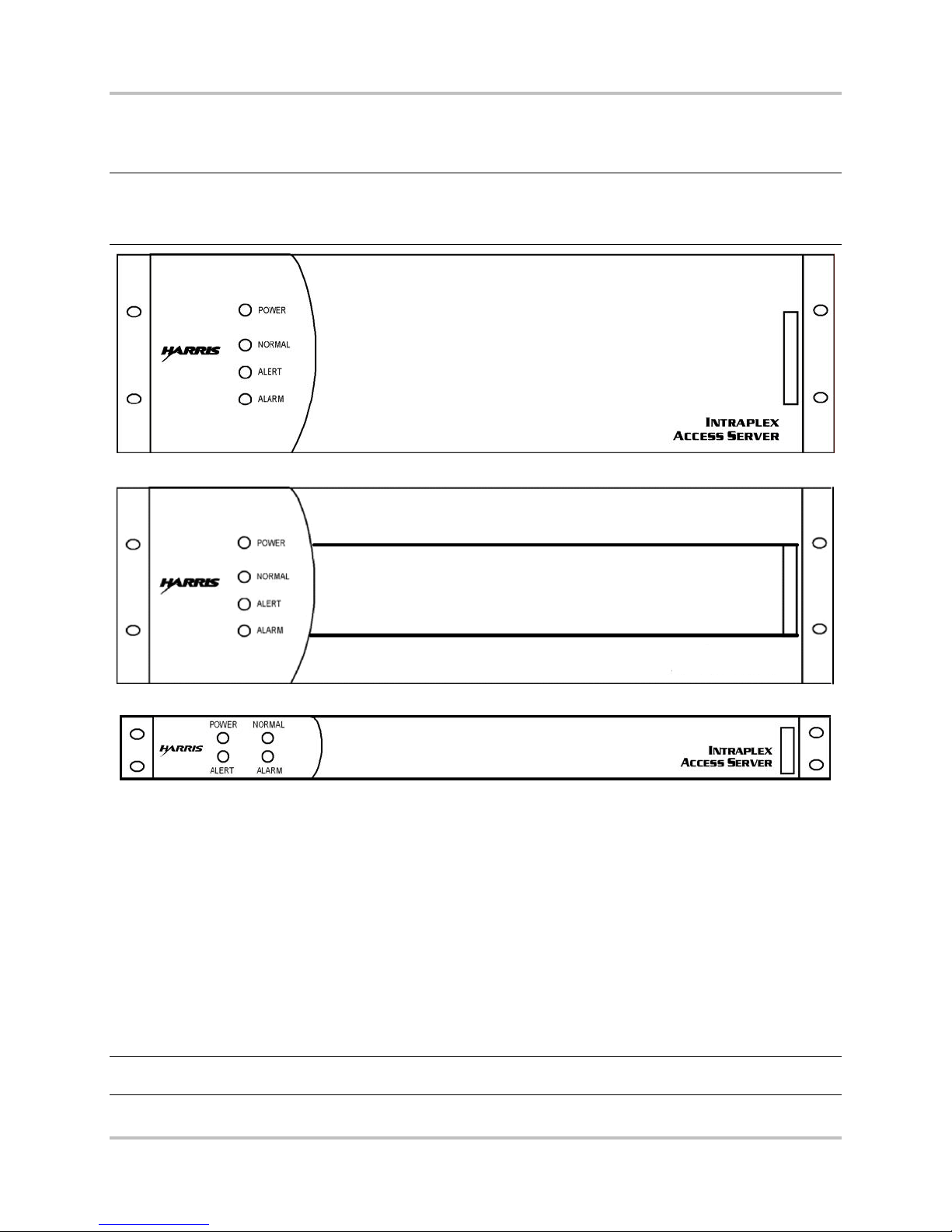
All ACS-160 Series and STL-160 Series multiplexers are rack-mountable in EIA standard 19" racks.
Full size, “3RU” shelves (ACS-163, ACS-165, ACS-166, STL-163, STL-165, and STL-166) are 5¼" high
(Figures 1-1 and 1-2). Compact, “1RU” shelves (ACS-167, ACS-168, and ACS-169) are 1¾" high
(Figure 1-3).
The 1RU versions perform the same functions as their 3RU counterpar ts but differ in the
● Number of channel modules they can accommodate
● Type of power supply used
● Physical orientation of th e modu les in the shelf
● Connection poin ts for alarm relays and a ring gener a tor
These differences are poin ted ou t in the appropriate sections throughout this manual.
Note: The ACS-166 and ACS-169 Dual Terminal Access Servers use different midpla nes from those
used in the ACS-163 Terminal Access Server, ACS-165 Drop and Insert Access Server, ACS168 Drop and Insert Access Server, STL-163 Studio-to-Transmitter Link , and STL-165 Studioto-Transmitter Link multiplexers. It is not possible to u s e th es e five multiplexers as dual
terminal access servers.
The ACS-163 and ACS-167 terminal multiplexers each terminate one T1 circuit. The ACS-165 and
ACS-168 multiplexers each terminate two T1 circuits and allow channels to pass between the two
circuits as well as to terminate at the multiplexer.
1-2 Harris Corporation
Intraplex Produc ts
1 – Introduction ACS-160 Series & STL-160 Series T1 Multiplexer Installation & Operation
INTRAPLEX
STL HD
Version 2.11, August 2011
The ACS-166 and ACS-169 product packages each provide two T1 terminal multiplexers in a single
shelf. The multiplexers share the same power su pply a nd alarm reporting system but are otherwise
independent; ther e is no communication between th e two T1 circuits.
Note: Unless oth er wise specified, all references to the ACS-163 multiplexer also apply to the ACS-
167 multiplexer, all refe rences to the ACS-165 multiplexer also apply to the ACS-168
multiplexer, an d a ll references to the ACS-166 multiplexer also apply to the ACS-169
multiplexer.
Figure 1-1. ACS-163, ACS-165, and ACS-166 Multiplexers, Front View (with cover)
Figure 1-2. STL-163, ST L -165, and STL-166 Multiplexers, Front View (with cover)
Figure 1-3. ACS-167, ACS-168, and ACS-169 Multiplexers, Front View (with cover)
1.4 Multiplexer Component Parts
1.4.1 Main Equipment Shelf
The main equipment shelf is 19" wide rack-mount, 5¼" high for a 3RU multiplexer or 1¾" high for a
1RU multiplexer. This equipment shelf has slots for
● Plug-in common modules
● Channel modules
● Module adapters
● Power supplies
Warning! All common modules , channel modules, and power s upp lies must be inserted so that the
white eject tab is at the bottom in a 3RU shelf and at the right in a 1RU shelf.
Harris Corporation 1-3
Intraplex Products

ACS-160 Series & STL-160 Series T1 Multiplexer Installation & Operation 1 – Introduction
Version 2.11, August 2011
1.4.2 CM-5RB Common Modules
There is one common module in a terminal multiplexer and two comm on modules in a dual terminal or
drop and insert multiplexer . Each CM-5RB common module provides one T1 port. Section 1.5 – CM5RB User Interface gives details on this c om m on module. For optional time delay capability, use the
CM-5R-TD module.
1.4.3 Channel Mo dules
There are one or more channel modules for
● Voice
● Data
● High fidelity audio
● Special applications
Each channel module may terminate one or more payload cir c uits (Section 2.1.6 – Channel Modules).
1.4.4 Module Adapters
All common and channel modules require module adapters, which inser t direc tly behind each module
and provide the circ uit connector(s). Every ch annel module works with at least one ty pe of module
adapter, and some channel modules are compatible w ith several module adapters, each one providing
a different type of connector or circuit interface.
Each CM-5RB common module is normally shipped with an MA-215 module adapter. The MA-215
adapter can support module redundancy through the addition of a CA-412 cable and a second CM-5RB
module. Systems preconfigured for module and line redundancy (for example, the ACS-163R-ACC
system) come equipped with two CM -5R B modules and (one each) MA-235-1 and MA-235-2 module
adapters. MA-215 and MA-235 module adapters provide RJ-48C T1 connections with CSU c apabilities.
Systems without line redundancy can be equipped with DB-15 T1 connectors by us ing MA-217B
module adapters.
1.4.5 Power Supplies
One power supply is always included, and a second one may be added in 3RU shelf systems for power
supply redundancy. ( A redu ndant power supply cannot be installed in a 1RU shelf.) Th e standard
power supply for the 1RU sh elf is a 30-watt, universal AC supply. There should be a minim um of 2RU
unoccupied space below th is s helf. For the 3RU shelf, the standard power supply is a 60-watt,
universal AC supply, with a minimum of 2RU unoc c upie d space below the shelf. There ar e a lso 50-watt
DC supplies for 3RU shelves, in -48VDC -24VDC versions, which require at least a 1RU of space
between shelves.
Intraplex also produ ces optional 95-watt supplies for use in 3RU shelves with high power
requirements. These a re a ls o universal AC supplies and also require a minimum of 2RU of un oc c upied
space below the shelf. (The type a nd number of channel modules in the multiplexer determine the
power requirements. Each channel module installation and operation manual gives power r e quirement
details. Section 7 – “Specifications” includes a listin g of Intraplex power supplies.) Figure 1-4 through
1-15 show the physical placement of the ACS-160 components in the equipment shelf.
1-4 Harris Corporation
Intraplex Produc ts
1 – Introduction ACS-160 Series & STL-160 Series T1 Multiplexer Installation & Operation
Version 2.11, August 2011
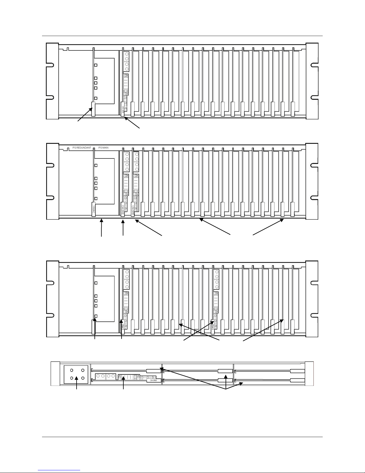
Primary Power Supply
CM-5RB
Figure 1-4. ACS-163 Multiplexer, Front View (no cover)
Primary Power Supply
Primary Power Supply
Power supply CM-57RB
DI-A
CM-5RB
DI-B
CM-5RB
16 slots for channel modules
Figure 1-5. ACS-165 Multiplexer, Front View (no cover)
First CM-5RB 16 slots for channel module s Second CM-5RB
Figure 1-6. ACS-166 Multiplexer, Front View (no cover)
5 slots for channel modules
Figure 1-7. ACS-167 Multiplexer, Front View (no cov er)
Harris Corporation 1-5
Intraplex Products
ACS-160 Series & STL-160 Series T1 Multiplexer Installation & Operation 1 – Introduction
Version 2.11, August 2011
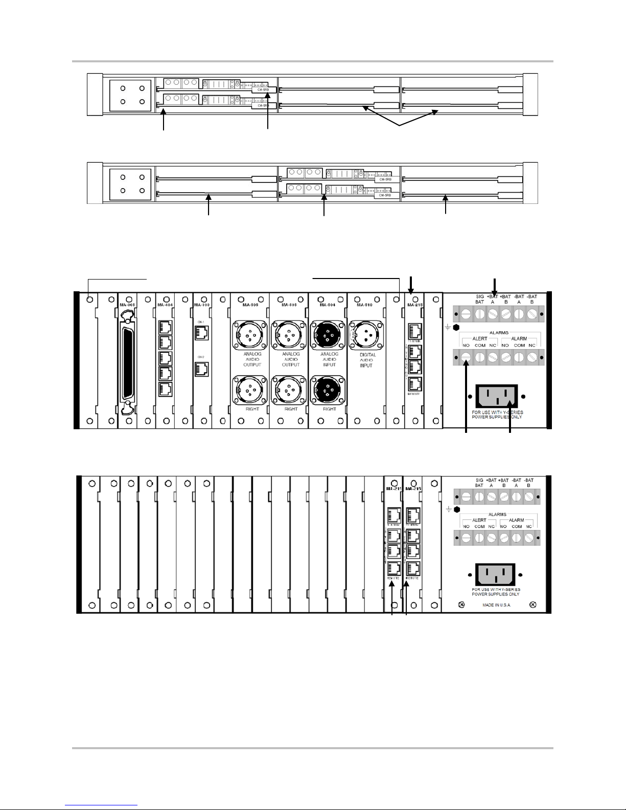
DI-B CM-5RB
DI-A CM-5RB
4 slots for channel modules
Figure 1-8. ACS-168 Multiplexer, Front View (No Cover)
Top CM-5RB controls these
channel modules
Two CM-5RBs
(ACS-169 only)
Bottom CM-5RB controls
these channel modules
Figure 1-9. ACS-169 Multiplexer, Front View (no cover)
Module adapters for common modules
MA-215 for
CM-5RB
Terminal strip 1
(DC power)
Terminal strip 2
(alert and alarm relays)
AC power in
Figure 1-10. Equipped ACS-163 Multiplexer, Rear View
Figure 1-11. ACS-165 Multiplexer, Rear View
1-6 Harris Corporation
Intraplex Produc ts
MA-215 for each CM-5RB
1 – Introduction ACS-160 Series & STL-160 Series T1 Multiplexer Installation & Operation
Version 2.11, August 2011
MA-215 for second CM-5RB MA-215 for first CM-5RB
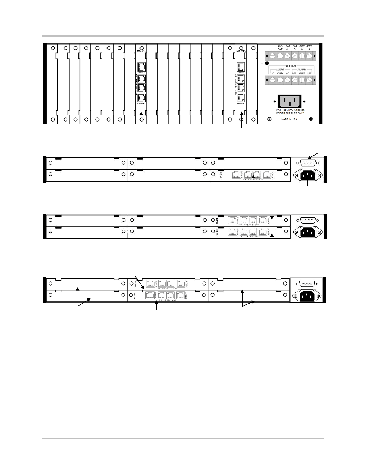
Figure 1-12. ACS-166 Multiplexer, Rear View
Connector for alarm out, signal
battery, and ring generator input
Figure 1-13. ACS-167 Multiplexer, Rear View
MA-215 for DI-B CM-5RB
MA-215 for DI-B CM-5RB
Figure 1-14. ACS-168 Multiplexer, Rear View
Bottom CM-5RB controls
these channel modules
MA-215 for first CM-5RB
MA-215 for first CM-5RB
Top CM-5RB controls
these channel modules
Figure 1-15. ACS-169 Multiplexer, Rear View
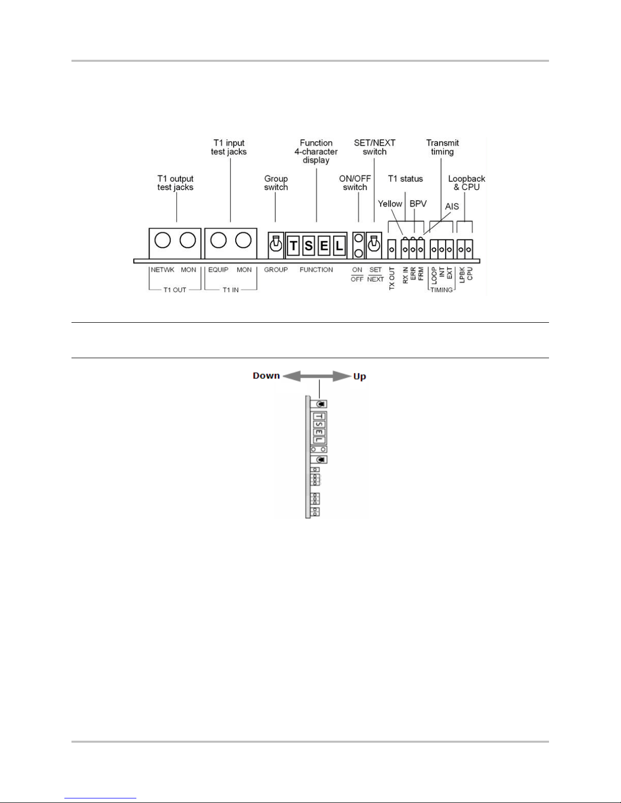
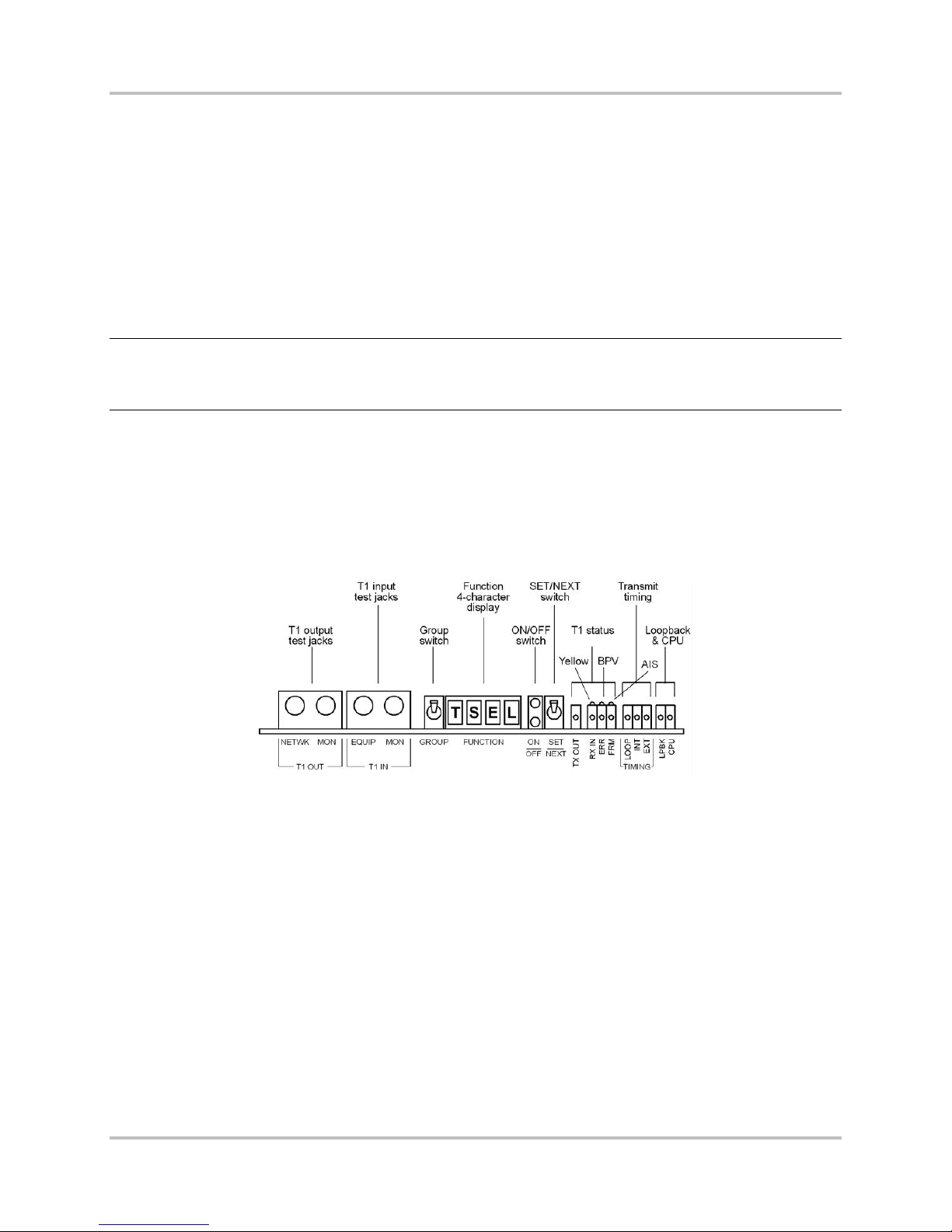
1.5 CM-5RB User Interface
This section describes the ACS-160 Series local user interface. Section 5 – “Remote Control O p er ation”
gives details on us ing the remote interface. The jacks, switches, and indicator lights on the CM-5RB
common module form the primary user interface f or the ACS-160 Series (Figure 1-16) multiplexers.
This user interface falls into three basic categories:
● Test Access: The left side of the module contains T1 input and output test jacks.
● Configuration: The center section contains these items that work together so that you can view
and change CM-5RB operational parameters:
• The GROUP and SET/NEXT switches
• A four-character alphanumeric display for abbreviated group and function names
• A bi-level indicator light set (gr een on top, red on bottom) that shows whether the function
displayed is currently active
Harris Corporation 1-7
Intraplex Products
ACS-160 Series & STL-160 Series T1 Multiplexer Installation & Operation 1 – Introduction
Version 2.11, August 2011
● Status Monitoring: Twelve indicator lights appear on the right side for
• T1 status
• Primary timing status
• Loopback activity
• CPU activity
Figure 1-16. CM-5RB Module, Front View
Note: Because CM-5RB m odules install vertically in 3RU sh e lves, “UP” and “DOWN” on the toggle
switches actually refer to right and left respectively in an ACS-163, AC S-165, ACS-166, STL163, STL-165, or STL-166 multiplexer (Figure 1-17).
Figure 1-17. CM-5RB GRO U P a n d SE T /NEXT Switches in 3RU Shelf
1.5.1 Function Gr oups and Configuration Switches
The user-accessible CM-5RB functions are organized into groups and include
● Setup options such as SF and ESF (frame formats).
● Current status c onditions such as receiving all ones .
● Informational items such as the CM-5RB firmware revision.
The groups are accessed f rom two dif ferent configuration group menus.
● Basic configurat ion: This group menu provid es the settings used in most configuration setups.
Section 3.2 – CM-5RB Basic C onfiguration Group Menu gives a detailed explanation of the menu
settings.
● Advanced configuration: This group menu provides settings for CM-5R-TD functions and other
specialized applications that rarely need adjustment in most systems. Section 3.3 – CM-5RB
Advanced Configuration Group Menu gives a detailed explanation of the menu settings.
1-8 Harris Corporation
Intraplex Produc ts

1 – Introduction ACS-160 Series & STL-160 Series T1 Multiplexer Installation & Operation
Version 2.11, August 2011
1.5.1.1 CM-5RB Function Displaying
When the CM-5RB display is blank or when a func tion is displayed, press down on the GROUP toggle
switch to view the name of the currently selected group. Once the current group name is display ed,
press down on the G ROUP switch again to select the next group or press up to select the previous
group, until the desired grou p is dis played.
Press down on the SET/NEXT switc h to display the first function in the currently selected group. Once
a function appears, press down on the SET/NEXT sw itc h repeatedly until the desired function is
displayed.
The bi-level indicator light set to the right of the function dis play indicates the status of the currently
displayed function. If the top (green) light is on, this function is active. If the bottom (red) light is on,
the function is not active.
1.5.1.2 CM-5RB Function Setting
To turn on a function that is not currently active, press up twice on the SET/NEXT switch while that
function is on the display. Pressing up once causes the top (green) light to blink, indicatin g that a
setup change takes place if the SET/NEXT switch is pressed up again. Actually pressing up on the
SET/NEXT switch a second time causes the green light to turn on continuously, indicating that the
selected setup parameter has been changed to the currently displayed setting. I f a function is already
active, pressing up on the SET/NEXT switch again causes no status or setup changes.
For example, if the display shows ESF while frame format is set to SF, the red light is on. Pressing up
on the SET/NEXT switch once causes the top (green) light to blink. Pressing up on the SET/NEXT
switch a second time actually changes the current T1 framing forma t from SF to ESF – the red light
goes out, and the green light stays on.
It is important to n ote that some setup functions are mu tually exclusive; activating one function
automatically deactivates another, such as
● Line code (you can set the line code to AMI or B8ZS but not both).
● Frame format (you can set the frame format to SF or ESF but not both).
Other functions are not mutually exclusive, such as the CM-5RB Line (LnLB) and Equipment (EqLB)
loopbacks in the LPBK group, which may both be activated at the same time.
1.5.2 Indicator Lights
In addition to the indicator lights on the CM-5RB common m od ule, four system status indicator lights
located on the power supply are visible when the front cover of the shelf is on (Figures 1-1 and 1-2).
Table 1-1 summarizes the meaning of the indicator lights on both the CM-5RB common module and
the power supply. For all the lights, “on” means the light is on continuously; “blink” means a rh ythmic,
one-half second on, one-half second off pulse; and “flash” means erratic flickering. Table 2-1 in
Section 2.1.3.7 gives more details for CM-5RB indicator lights, and Table 2-8 in Section 2.1.5 gives
more details for pow er supply indicator lights.
Harris Corporation 1-9
Intraplex Products

ACS-160 Series & STL-160 Series T1 Multiplexer Installation & Operation 1 – Introduction
Version 2.11, August 2011
Table 1-1. CM-5RB and P ower Supply Status Indicator Lights
Indicator
Light Group Light Description
T1 Status
(CM-5RB)
T1 Error and
Alarm
(CM-5RB)
Timing
(CM-5RB)
System
Status
(CM-5RB)
System
Status
(Power
Supply)
TX OUT (Green) On when transmit output is detected.
RX IN (Green) On when receive input is detected. Blinks steadily when the receive input signal is
all ones, a yellow alarm, or has excess jitter. May flash if there is excess noise on
the input signal.
ERR (Yellow) On when logic errors are detected.
BPV On when bipolar violations are detected .
FRM (Red) On when T1 signal is out of frame or no signal is being received.
YEL (Yellow) On when there is a yellow alarm.
AIS On when an Alarm Indication Signal (AIS) has been detected.
LOOP (Green) On when loop timing is active (through timing on a drop/insert multiplexer).
INT (Green) On when internal timing is active.
EXT (Green) On when exter nal timi ng is active .
LPBK (Yellow) On when any inte rnal loopback is active.
CPU (Red) On when the CM-5RB central processing unit has failed.
POWER (Green) On when the multiplexe r is powe re d .
NORMAL (Green) On when no alert or alarm is present.
ALERT (Yellow) On when an alert condition exists.
ALARM (Red) On when an alarm condition exists. Section 6.3.5 defines alert and alarm
conditions.
1-10 Harris Corporation
Intraplex Produc ts

No header here
Section 2 – Functional Design
This section expla ins the functions of the ACS-160 and STL-160 Series multiplexer components and
describes how to us e the multiplexers to configure both point-to-point and drop and insert T1
systems.
2.1 Component Func tionality
2.1.1 Main Equipment Shelf and Midplane
All modules, module adapter s , a nd power supplies plug into the main equipment shelf. These
components commu nicate with each other via the shelf midplane (or motherboard), which contains
both signal and power d is tribution buses (Figure 2-1).
Note: The ACS-166 and ACS-169 Dual Terminal Access Servers use different midpla nes from those
used in the ACS-163 Terminal Access Server, ACS-165 Drop and Insert Access Server, ACS168 Drop and Insert Access Server, STL-163 Studio-to-Transmitter Link , and STL-165 Studioto-Transmitter Link multiplexers. It is not possible to use these five multiplexers as dual
terminal access servers.
Power enters at eith e r the AC or battery connectors and passes to the power supply. The power supply
provides three voltages to th e power distribution bus (+5 VDC, +15 VDC, and -15 VDC), from which
each common and channel modu le dr a w s c urrent as needed. Power supplies from the signaling battery
and ring generator, if u sed, also connect to the power distribution bus.
Harris Corporation 2-1
Intraplex Products
Figure 2-1. Midplane Connections
ACS-160 Series & STL-160 Series T1 Multiplexer Installation & Operation 2 – Functional Description
Version 2.11, August 2011
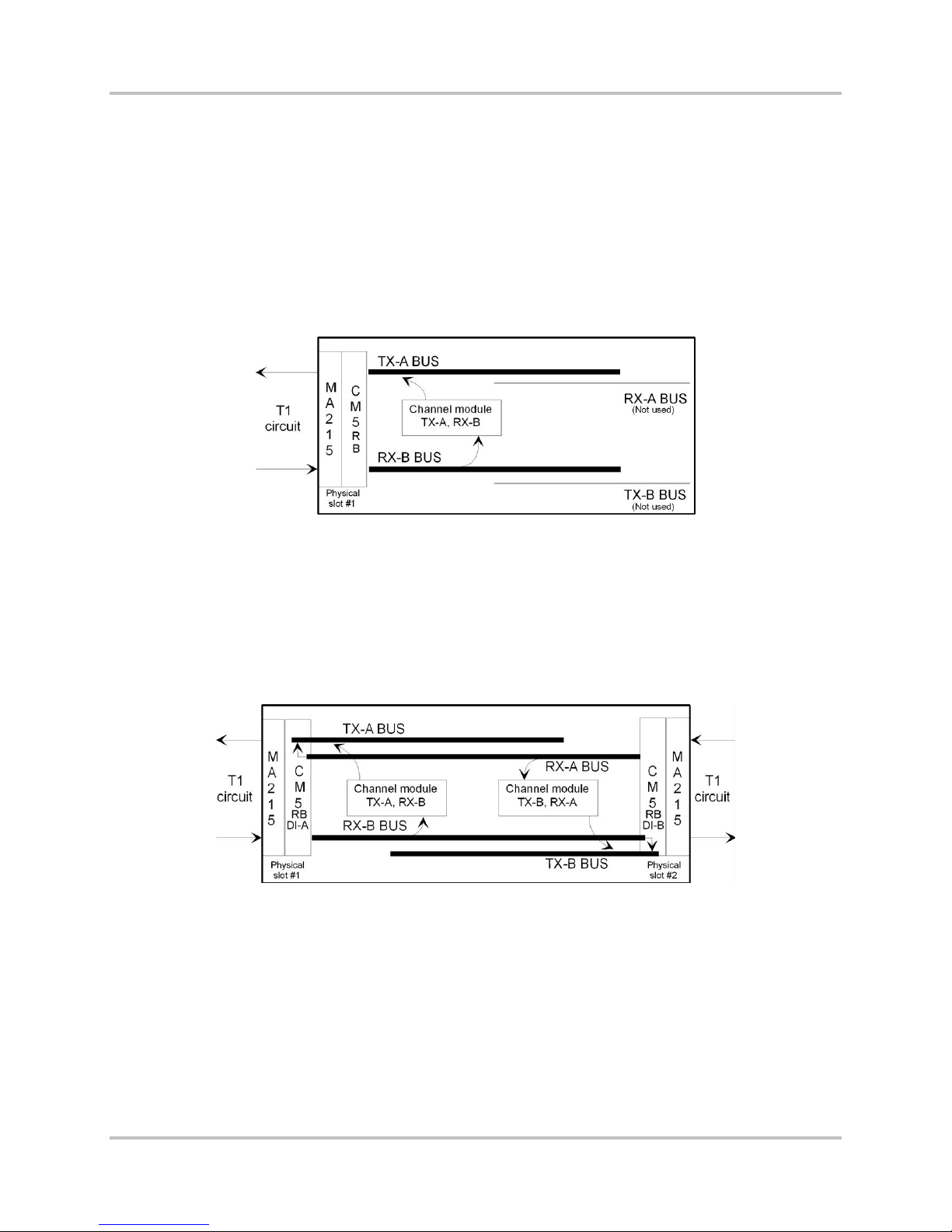
2.1.2 Drop and Insert Operation: the Signal Bus Role
The signal bus actually includes four buses:
● TX A bus
● RX A bus
● TX B bus
● RX B bus
In a terminal multiplexer, the channel modules pla c e their transmit signals on the TX A bus. The CM5RB common module ta kes these signals and multiplexes them together for transmiss ion on the T1
line. It also takes the incoming T1 signal, demultiplexes it, and places the resulting c hannel signals on
the RX-B bus, from which the channel modules take their individual rec eive data (Figure 2-2).
Figure 2-2. Terminal Multiplexer Signal Bu s
Each channel module has a bus selection switch that sets its transmit and receive directions. This
switch is generally labeled TX-A BUS or TERM. Setting the TX-A BUS or TERM switch on ensures that
the module transmits on the TX-A bus and receives from the RX-B bus, as required in a terminal
multiplexer.
In a drop and insert multiplexer, setting the TX-A BUS or TERM switch on sets a channel module to
transmit and rece ive via the CM-5RB module designated as DI-A. Settin g the TX-A BUS or TERM
switch off (up) sets a channel module to transmit and r eceive via the CM-5RB module designated as
DI-B, using the TX-B bus and the RX-A bus (Figure 2-3).
Figure 2-3. Drop and Insert Multiplexer Signal Bus
On some older channel module designs, there are two switches, one for the transmit side and one for
the receive side. These two switches should alway s be set to opposite dire c tions. In a terminal
multiplexer, or to communicate via the DI-A port in a drop and insert multiplexer, set the sw itches to
transmit A, rece ive B. To communicate via the DI-B port in a drop and insert multiplexer, set the
switches to trans m it B, receive A. Individual channel module manuals give the location and labe ling of
these switches on the modules provided with this sy stem.
As Figure 2-3 shows, in a drop and insert multiplexer, the RX-A bus connects to the TX-A bus, and the
RX-B bus connects to the TX-B bus. When there are no active channel modules in a dr op a nd insert
multiplexer, all T1 signal time slots coming from each direction transfer to the outgoing T1 signal in
the other directi on. When any transmit-only or full duplex channel modules are insta lled a nd active,
their output overrides th e data coming through on their selected time slot(s). Data in time s lots not in
2-2 Harris Corporation
Intraplex Produc ts
2 – Functional Des c ription ACS-160 Series & STL-160 Series T 1 M ultiplexer Installation & Operation
Version 2.11, August 2011
use by any local channel module pass es th r ough as before. You can use a receive-only channel
module to monitor a channel passing through without affecting its passage.
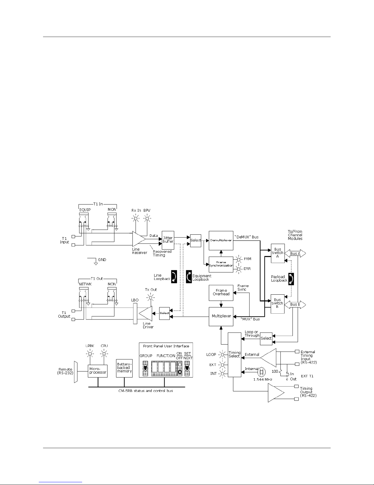
2.1.3 CM-5RB Common Modules
The CM-5RB common module, the c or e building blocks of ACS-160 and STL-160 Series multiple xers,
provides one full-duplex T 1 port. The ACS-163 or ACS-167 terminal multiplexer has one CM-5RB
module. The ACS-166 or ACS-169 dual terminal multiplexer, or the ACS-165 or ACS-168 drop and
insert multiplexe r , has two CM-5RB modules.
The CM-5RB module provides these basic operational fu nctions:
● Channel multiplexing to form the T1 aggregate
● T1 line driver (output)
● Transmit timing functions
● T1 line receiver (input)
● T1 aggregate demultiplexing to individual channels
● Loopback configurations
● Microprocessor control
● User interface
Figure 2-4 shows a fu nctional diagram of the CM-5RB module.
Figure 2-4. CM-5RB Common Module T1 Functional Diagram
Harris Corporation 2-3
Intraplex Products

ACS-160 Series & STL-160 Series T1 Multiplexer Installation & Operation 2 – Functional Description
Version 2.11, August 2011
2.1.3.1 Channel Multiplexing to Form T1 Aggregate
The CM-5RB common module develops midplane bu s synchronization signals. The tr ansmit section of
each channel mod ule synchronizes to these signals a nd places its data onto the selected bu s. The CM5RB module then form s the aggr ega te signal, using either the ESF (extended superf ra m e) or S F ( D 4
superframe) framin g format. ESF is the preferred format and you should use it in all cases except
when the network or CSU cannot support it. Section 2.2.1.1 – T1 Frame Formats gives more details on
these two formats.
The CM-5RB module uses tri-state bus drivers and receivers to permit routin g the multiplexer and
demultiplexer bus signals t o eith er midplane bus (Bus A or Bus B). This versatile bus capability
enables simple multiplexer configuration for terminal or drop and in sert use (Section 2.1.2 - Drop and
Insert Operation : the Signal Bus Role).
2.1.3.2 T1 Line Driver
Line coding can be s et to either B8ZS (Bipolar with 8 Zero Substitution) or AMI (alternate mark
inversion). B8ZS is the preferred format; you should always use B8ZS, unless the network or channel
service unit cannot support it. Section 2.2.1.2 – T1 Line Coding gives a des c r iption of these line coding
methods.
Equipment and monitor test jacks on the front of the m odule accept input of miniature bantam plugs.
They allow the T 1 output of the multiplexer to be connec te d to a T1 transmission test set or to be fed
directly into the in p ut of another multiplexer during be nch testing.
The T1 line output connection is via the MA-215 module adapter. In s er tin g a plug into the T1
equipment out jack b r eaks the outgoing connection to the MA-215 module adapter. Terminating
impedance should be 100 ohms ba la nced. The T1 monitor out jack permits test access to the line
output without brea king the T1 line connection. Equ ip m ent connected to this jack shou ld also provide
a 100 ohm terminati on impedance. The signal level a t this point is approximately 20 decibels below
the line output level.
2.1.3.3 T1 Line Receiver
T1 input should be at the standard DS-1 digital cross connect level (DSX-1). T1 frame format can be
either ESF or SF. The line code can be either B8ZS (bipolar with 8-zero substitution) or AMI (a lte r nate
mark inversion). The lin e receiver
● Accepts the input signal.
● Recovers receive timing.
● Decodes the bipolar s ig nal.
A jitter buffer f ollows to smooth out the timing jitter usually present on an incoming signal.
The CM-5RB module receives T1 line input via the MA-215, MA-216, MA-217B, MA-235-1, or MA-235-
2 module adapter. Equipment and monitor T1 in jacks function like the T1 out jacks described
previously. All eq uipment connected to them should provide 100 ohms termination. T he equipment in
jack breaks th e c onnection to the T1 line input; the mon itor in jack does not, but the sign al level at
the monitor jack is about 20 decibels below the input level.
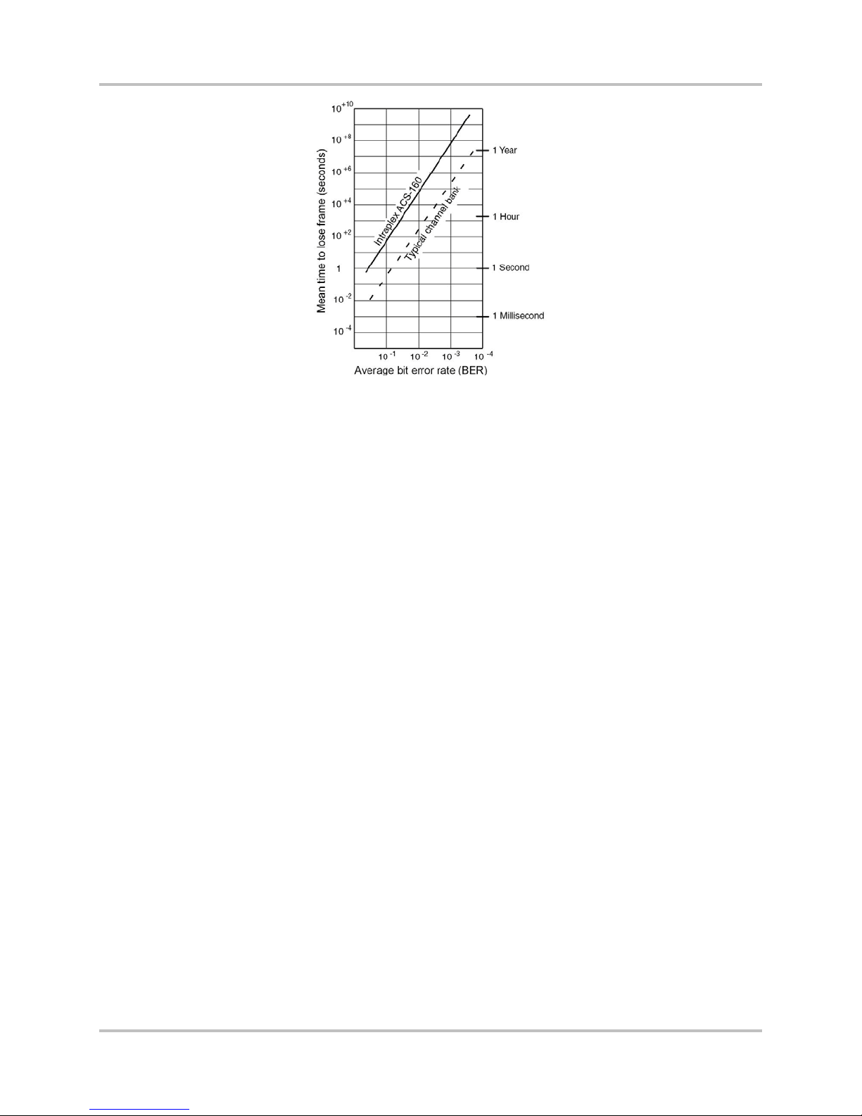
2.1.3.4 T1 Aggregate Demultiplexing to Individual Channels
The decoded line receive signal feeds the demultiplexer circuitry. First, the dem ultiplexing circuitry
achieves frame synchronization, using a proprietary robust framing algorithm that assures fast frame
acquisition and a high tolerance to errors once a frame is acquired. The average frame time for the SF
format is 4 milliseconds and for the ESF format is less than 18 milliseconds. Mean time to lose frame
in the presence of a high (10
-3
) random bit error rate exc eeds s everal hours (Figure 2-5).
2-4 Harris Corporation
Intraplex Produc ts
2 – Functional Des c ription ACS-160 Series & STL-160 Series T 1 M ultiplexer Installation & Operation
Version 2.11, August 2011
Figure 2-5. Mean Ti me to Lose T1 Frame Synchronization
Once frame synchroniza tion is achieved, the demultiplexer develops the proper dem ultiplexing bus
signals and feeds them to all the channel modules plugged in to th e s helf. Bus signals include
● Demultiplexed chann el da ta .
● Demultiplexing sy nchronization status.
● Synchronization signals necessary for proper dec oding by the channel modules.
2.1.3.5 Loopback Configurations
The CM-5RB common module provides three loopback options (Figure 2-4):
● Line – Use the line loopback to test the transmission path integrity and th e T1 connections to the
multiplexer. This loopback takes the decoded T1 receive signal coming f r om the line receiver/jitter
buffer and loops it back to the T1 line driver input. Receive data also pas ses on to the
demultiplexer.
● Payload – Use the payload loopback to verify CM-5RB module operation up to the bus interface to
the channel module s . Data also passes on to the receive side of the channel modules.
● Equipment – Use the equipment loopback to test individual c hannel modules in the multiplexer.
It loops the transm it s ignals at the multiplexer output back to the demultiplexer in put. During
equipment loopba c k, the T1 output of the CM-5RB module is an all-ones signal.
Section 5.2.3.2 – Shelf-Level and Common Module Remote Ac c es s gives more information on
loopbacks.
2.1.3.6 Microprocessor Control and Battery-Backed Memory
The microprocessor chip used on all Intraplex common m od ules contains a lithium battery, which is an
inextricable element of th e m icr oproc es sor and is not independently replaceable. The lithium battery
powers the memory on the chip and thus retains setu p information whenever operating power is
removed, which might occur at any of these times:
● When equipment is stored or in transit
● When the module containing the chip is removed from a powered shelf
● When there is a tem p or a r y loss of power, other than unintentional or c atastrophic
In the design of Intraplex equipment, battery failure does not affe c t p r oper operation while the
equipment is under operati ng power. Battery failure does not become evident until power is removed
and the equipment is subsequ ently repowered. Upon repowering, the alphanumeric disp la y on the
common module flas hes “ERR 0” or remains blank.
Harris Corporation 2-5
Intraplex Products
ACS-160 Series & STL-160 Series T1 Multiplexer Installation & Operation 2 – Functional Description
Version 2.11, August 2011
The lithium battery on the microprocessor chip has a data retention time of at least 10 years and an
expected shelf life of at least 20 y ea r s . In this context, “data retention time ” is the time when power is
removed (the battery is active) , and “shelf life” is the time when the shelf is powered ( th e ba ttery is
inactive).
Intraplex maintenance offers equipment repair by replacing inoperative plug-in modules. A failed
lithium battery c auses the common module on which the battery is mounted to fail. (Although, as
previously stated, this failure does not actually oc cur until operating power is rem oved and restored.)
To restore the mult iplexer to service, perform these steps:
1. Replace the failed module with a spare common module.
2. Return the failed unit to the factory for microprocessor replacement.
Warning! Intraplex common modu les may contain replaceable batteries. There is a danger of
explosion if a repla c ea ble battery is incorrectly replaced. Only replace this ba ttery with the
same or equivalent type recom mended by the manufacturer. Dispose of used batteries
according to the manufacturer’s instructions .
2.1.3.7 CM-5RB User Interface
To enable user settings and display status information, the front edge of the CM-5RB module (Figure
2-6) has
● Two switches.
● A four-character alphanumeric display.
● Several indicator l ig hts.
Figure 2-6. CM-5RB Common Module, Front View
Use GROUP and SET/NEXT Switches and Alphanumeric Display
The user-accessible CM-5RB module functions are organized into groups, which include
● Setup options such as SF and ESF (frame formats).
● Current statu s c onditions such as receiving all ones.
● Informationa l item s such as the CM-5RB firmware revision.
Detailed explan ations of the basic CM-5RB functions appear in these sections:
● T1 operational functions (TIME and TSEL) in Section 4 – “Setup and Configuration”
● Remote access setup functions (ADDR and SIO) in Section 5 – “Remote Control Operati on”
● Diagnostic functions (LPBK, BLNK, RVU1, and DIAG) in Section 6 – “Testing and
Troubleshooting”
Use the GROUP switch to select a particular function group and the SE T/NEXT switch to view and
set functions within the currently selected group. The four-character alphanumeric display shows
2-6 Harris Corporation
Intraplex Produc ts

2 – Functional Des c ription ACS-160 Series & STL-160 Series T 1 M ultiplexer Installation & Operation
Version 2.11, August 2011
both group and function names, and the bi-level ON/OFF indicator lights sign ify the status of the
currently displayed function.
Display CM-5RB Functions
To display the CM-5 R B functions, perform these steps:
1. When the CM-5RB display is blank or w hen a function is displayed, press down on the group
toggle switch to view the name of the currently selec ted gr oup.
2. Once the current group name is displayed, press down on the group switch again to select the
next group or press up to select the previous group, until the desired group is displayed.
3. Press down on the SET/NEXT switch to display the first fun c tion in the currently selected
group.
4. Once a function appears, press down on the SE T/NEXT switch repeatedly until the desired
function is displa yed.
The bi-level light to the r ight of the function display indicates the status of the currently displayed
function. If the top (green) light is on, this function is active. If the bottom (red) light is on, the
function is not active.
Set CM-5RB Functions
To turn on a function that is not currently active, press up twice on the SET/NEXT switch while
that function is on the display. Pressing up once causes the top (green) light to blink, indicating
that a setup change takes place if the SET/NEXT switch is pressed up again. Actually pressing up
on the SET/NEXT switch a second time causes the top (gree n) light to turn on continuously,
indicating that the selected s etup parameter has been changed to the currently displayed s etting.
If a function is already active, pressing up on the SET/NEXT switch again causes no status or
setup changes.
For example, if th e d is p la y shows ESF while frame format is s e t to SF, the red light is on. Pressin g
up on the SET/NEXT switch once causes the top (green) light to blink. Pressing up on th e
SET/NEXT switch a second time actually changes the current T1 framing format from SF to ESF—
the red light turns off, and the green light is on continuously.
It is important to n ote that some setup functions are mu tually exclusive; setting on e function
automatically deactivates another. Examples include
● Line code (you can set line code to AMI or B8ZS but not both).
● Frame format (you can set frame format to SF or ESF but not both).
Other functions are not mutually exclusive. For ex ample, CM-5RB Line (LnLB) and Equipment
(EqLB) loopbacks in the LPBK group may be set at the same time.
Read CM-5RB Module Indicator Lights
Table 2-1 gives CM-5RB indicator lig ht descriptions. For all the lights, ON m eans the light is on
continuously; BLINK means a rhythmic, one-half second on, one-half second off pulse; and FLASH
means erratic flickering.
Harris Corporation 2-7
Intraplex Products

ACS-160 Series & STL-160 Series T1 Multiplexer Installation & Operation 2 – Functional Description
Version 2.11, August 2011
Table 2-1. CM-5RB Indicator Lights
Light Description
TX OUT
(green
RX IN
(green)
ERR
(yellow)
YEL
(yellow)
BPV
(yellow)
AIS
(yellow)
FRM
(red)
LOOP
(green)
INT
(green)
EXT
(green)
LPBK
(yellow)
Transmit output
ON The transmissio n signa l is normal. I t can be a data signal or, if idle, an all-ones signal.
OFF No signal is being transmitted, indicating a hardware failure.
Receive input
ON A data signal is detected at the C M-5RB T1 rece ive r inp ut.
OFF No signal is dete c ted at the receiv er inp ut.
BLINK One of these signals or conditions is d e tecte d (se e n on the BLNK group disp lay):
Rx11 - A framed or unframed all-ones signal, produced by an idle condition at the far end (an
unframed all ones is a T1 alarm indication signal (AIS ))
RxYL - A yellow alar m , ind ic a ting a loss of the rece ive s ignal at the far end (if the equipment
at the far end is set up to generate a yellow alarm)
XsJt - Excess jitter, indicating the jitte r buffer depth has been exceeded. This light might
flash if there is noise on the line.
Errors
FLASH Light flashes each time a CRC-6 error is detected.
Yellow alarm
ON An “upstream” failur e . Loss of signa l dete c ted fro m an upstream source.
Bipolar violations
FLASH A light flashes each time a bipolar violation is detected.
ON The random bit error ratio excee d s 10-5.
Alarm Indication Signal
ON An upstream failure has been detected.
Out of frame
ON CM-5RB T1 receiver is not in frame synchronization, which might b e caus ed by a high bit
error ratio, the absence of a T1 receive signal, or improper CM-5RB module configuration.
Loop or through timing
On ACS-163 terminal multiple x e r
ON The T1 transmitter is loop timed.
BLINK The loop is selected for primary timing, but the module is currently using fallb a c k timing .
On ACS-165 drop and insert multiplexer
ON The T1 transmitter is through timed.
BLINK Through is selected for primary timing, but the module is currently using fallback timing .
Internal timing
ON The CM-5RB transmitter is using its internal 1.544 MHz clock.
External timing
ON The CM-5RB transmitter is using timing provided by an external cl o ck .
BLINK External is selected for primary timing, but the module is currently using fallbac k timing .
Loopback
ON One or more of three internal CM-5RB loopbacks (line, equip m e nt, or pay load ) is active.
2-8 Harris Corporation
Intraplex Produc ts
 Loading...