

Harris SG5300 Product Manual

Product Manual
MM-018623-001
Rev. D, Mar/15
SG5300 Data Modem
800 MHz and 900 MHz
MM-018623-001, Rev. D
without any warranty. Improvements and changes to this manual neces sitated by typographical errors,
at any time and without notice.
n any form or by any means,
Copyright © 2011 – 2013, 2015, Harris Corporation. All rights reserved.
MANUAL REVISION HISTORY
REV DATE REASON FOR CHANGE
- Jul/11 Initial release.
A Oct/11 Revised DNP3 information and AT command list in Table 7-1.
B May/12 Revised firmware installation and configuration instructions. Updated Warranty statement.
C Sep/13 Updated to include non-incendive rating information.
D Mar/15 Added serial tunneling information.
CREDITS
Harris, assuredcommunications, EDACS, and OpenSky are registered trademarks and NetworkFirst and the OpenSky2 logo
are trademarks of Harris Corporation.
Conxall and Multi-Con-X are registered trademarks of Conxall Inc.
Band-it is a registered trademark of BAND-IT-IDEX, Inc. A Unit of IDEX Corporation
All other brand and product names are trademarks, registered trademarks, or service marks of their respective owners.
NOTICE!
The material contained herein is subject to U.S. export approval. No export or re-export is permitted without written approval
from the U.S. Government. Rated: EAR99; in accordance with U.S. Dept. of Commerce regulations 15CFR774, Export
Administration Regulations.
Information and descriptions contained herein are the property of Harris Corporation. Such information and descriptions may
not be copied or reproduced by any means, or disseminated or distributed without the express prior written permission of
Harris Corporation, PSPC Business, 221 Jefferson Ridge Parkway, Lynchburg, VA 24501.
Repairs to this equipment should be made only by an authorized service technician or facility designated by the supplier. Any
repairs, alterations or substitutions of recommended parts made by the user to this equipment not approved by the
manufacturer could void the user's authority to operate the equipment in addition to the manufacturer's warranty.
This product conforms to the European Union WEEE Directive 2012/19/EU. Do not dispose of this product in a
public landfill. Take it to a recycling center at the end of its life.
This manual is published by Harris Corporation
inaccuracies of current information, or improvements to programs and/or equipment, may be made by Harris Corporation
Such changes will be incorporated into new editions of this manual. No part of this manual may be reproduced or transmitted i
electronic or mechanical, including photocopying and recording, for any purpose, without the express written permission of Harris Corporation.
2

MM-018623-001, Rev. D
Section Page
8 ETHERNET FIRMWARE INSTALLATION AND CONFIGURATION ............................ 31
TABLE OF CONTENTS
1 REGULATORY AND SAFETY INFORMATION .................................................................... 6
1.1 REGULATORY
1.1.1 Transmitter ............................................................................................................... 6
1.1.2 Receiver .................................................................................................................... 6
1.1.3 FCC Compliance ...................................................................................................... 6
1.1.4 Industry Canada ........................................................................................................ 6
1.2 SAFETY
1.3 RF
SYMBOL CONVENTIONS ................................................................................. 7
ENERGY EXPOSURE INFORMATION ....................................................................... 8
1.3.1 Safety Training Information ..................................................................................... 8
1.3.2 Contact Information.................................................................................................. 9
1.3.3 Occupational Safety Guidelines and Safety Training Information ........................... 9
1.4 DIVISION
2 INTRODUCTION ........................................................................................................................ 11
2.1 ABOUT
THIS MANUAL ................................................................................................... 11
2.2 GLOSSARY
3 DESCRIPTION ............................................................................................................................ 12
3.1 MULTIPLE
3.2 OVER-THE-AIR
3.3 VERSATILE
APPROVALS ............................................................................................ 6
2 NON-INCENDIVE PROTECTION .............................................................. 10
OF TERMS .................................................................................................... 11
APPLICATIONS ............................................................................................ 12
PROGRAMMING .................................................................................. 13
MOUNTING ................................................................................................. 13
4 OPERATION ............................................................................................................................... 14
4.1 STARTING
THE SG5300 ................................................................................................... 14
4.2 INDICATORS ..................................................................................................................... 15
5 UNPACKING AND CHECKING EQUIPMENT..................................................................... 16
5.1 UNPACKING EQUIPMENT .............................................................................................. 16
5.2 INSPECTING
5.3 ITEMS
INCLUDED ............................................................................................................ 16
5.4 OPTIONS
AND INVENTORYING EQUIPMENT ..................................................... 16
AND ACCESSORIES ....................................................................................... 17
6 INSTALLATION ......................................................................................................................... 18
6.1 GENERAL
6.2 SITE
6.3 EQUIPMENT
6.4 MOUNTING
6.5 SURGE
PLANNING ..................................................................................................... 18
GROUNDING ............................................................................................................ 18
INSTALLATION ........................................................................................ 18
THE SG5300 ................................................................................................. 19
PROTECTION ...................................................................................................... 21
6.6 CONNECTIONS ................................................................................................................. 21
6.6.1 Power Connections ................................................................................................. 21
6.6.2 Safety/Earth Ground ............................................................................................... 22
6.6.3 Antenna Installation ................................................................................................ 23
6.6.4 Ethernet Data Interface Connection ....................................................................... 23
6.6.5 Serial Data Interface Connection ............................................................................ 24
7 CONFIGURATION ..................................................................................................................... 26
7.1 EQUIPMENT
7.2 CONFIGURING
7.3 CONFIGURING
REQUIRED ................................................................................................. 26
THE RF RADIO ...................................................................................... 26
THE ETHERNET PORT ......................................................................... 28
3

MM-018623-001, Rev. D
Section Page
8.1 UPDATE ETHERNET DEVICE FIRMWARE .................................................................. 31
TABLE OF CONTENTS
8.1.1 Set Server IP Address ............................................................................................. 31
8.1.2 Install Software ....................................................................................................... 31
8.2 CONFIGURATION ............................................................................................................ 33
8.2.1 Load Factory Defaults ............................................................................................ 33
8.2.2 Set Server IP Address ............................................................................................. 33
8.2.3 Serial Channel and Network Configuration ........................................................... 34
8.3 IMPLEMENTATION ......................................................................................................... 38
8.4 IMPLEMENTATION
8.4.1 Sample Implementation, SG5300 and One Logical Network ................................ 39
8.4.2 Sample Implementation, SG5300 and Two Logical Networks .............................. 42
8.4.3 Sample Implementation, SG5300, 2 Logical Networks, and Multiple Devices ..... 44
9 DISTRIBUTED NETWORK PROTOCOL (DNP3) ................................................................ 47
9.1 DNP3
COMMANDS ........................................................................................................... 48
9.2 ESTABLISHING
9.3 DNP3/IP
ADDRESSING .................................................................................................... 49
9.3.1 DNP3/IP Routing Table ......................................................................................... 49
9.3.2 Static Addressing .................................................................................................... 49
9.3.3 Dynamic Addressing .............................................................................................. 51
9.3.4 Broadcast Address .................................................................................................. 51
EXAMPLES .................................................................................... 39
SERIAL COMMUNICATIONS ............................................................ 48
10 SERIAL TUNNELING ............................................................................................................... 52
10.1 SERIAL
10.2 ESTABLISHING
TUNNELING COMMANDS ............................................................................... 52
SERIAL COMMUNICATIONS ............................................................ 54
10.2.1 Static Tunneling ...................................................................................................... 54
10.2.2 Network Initiated Serial Tunneling ........................................................................ 55
10.2.3 Client Initiated Serial Tunneling ............................................................................ 55
11 TROUBLESHOOTING AND SERVICING ............................................................................. 57
11.1 TROUBLESHOOTING ...................................................................................................... 57
11.2 SERVICING ........................................................................................................................ 57
12 CUSTOMER SERVICE .............................................................................................................. 58
12.1 TECHNICAL
12.2 CUSTOMER
ASSISTANCE ............................................................................................. 58
CARE ............................................................................................................ 58
13 SPECIFICATIONS ...................................................................................................................... 59
13.1 GENERAL
13.2 TRANSMITTER
13.3 RECEIVER
13.4 DIGITAL
ARRANTY REGISTRATION ................................................................................................ 61
14 W
SPECIFICATIONS .......................................................................................... 59
SPECIFICATIONS ................................................................................. 60
SPECIFICATIONS ......................................................................................... 60
OPERATION ..................................................................................................... 60
4

MM-018623-001, Rev. D
Figure 3-1: SG5300 Data Modem ....................................................................................................... 12
Table 1-1: MPE Table ........................................................................................................................... 9
LIST OF FIGURES
Page
Figure 3-2: SG5300 System Application ............................................................................................. 13
Figure 4-1: SG5300 Controls and Indicators ....................................................................................... 14
Figure 6-1: SG5300 Physical Dimensions ........................................................................................... 20
Figure 6-2: Serial Port Protective Cover for Division 2 Non-Incendive Applications ........................ 25
Figure 7-1: Rebooting Example .......................................................................................................... 27
Figure 8-1: SG5300 and One logical network ..................................................................................... 39
Figure 8-2: SG5300 and Two Logical Networks ................................................................................ 42
Figure 8-3: SG5300, Two Logical Networks, and Multiple Devices .................................................. 44
Figure 9-1: DNP3 Protocol Example................................................................................................... 47
Figure 9-2: DNP3 Static Addressing Example .................................................................................... 50
Figure 9-3: Adding a DNP3 Static Routing Table .............................................................................. 51
LIST OF TABLES
Page
Table 2-1: Glossary of Terms .............................................................................................................. 11
Table 4-1: Indicators and Controls ...................................................................................................... 15
Table 6-1: Surge Protection Options ................................................................................................... 21
Table 6-2: SG5300 Connections ......................................................................................................... 21
Table 6-3: Ethernet Interface Signals ................................................................................................. 23
Table 6-4: Ethernet LEDs ................................................................................................................... 24
Table 6-5: Serial Interface Signals ...................................................................................................... 25
Table 7-1: Useful SG5300 AT Commands ......................................................................................... 28
Table 9-1: Commands Associated to DNP3 ........................................................................................ 48
Table 9-2: DNP3/IP Routing Table ..................................................................................................... 49
Table 10-1: Commands Associated to Serial Tunneling ..................................................................... 52
Harris Corporation, Public Safety and Professional Communications (PSPC) Business continually evaluates its technical
publications for completeness, technical accuracy, and organization. You can assist in this process by submitting your
comments and suggestions to the following:
Harris Corporation fax your comments to: 1-434-455-6851
PSPC Business or
Technical Publications e-mail us at: PSPC_TechPubs@harris.com
221 Jefferson Ridge Parkway
Lynchburg, VA 24501
5
MM-018623-001, Rev. D
population; consult Safety Code 6, obtainable from Heath Canada’s website
1 REGULATORY AND SAFETY INFORMATION
1.1 REGULATORY APPROVALS
1.1.1 Transmitter
The transmitting devices listed below have been tested and meet the following regulatory requirements:
MODEL DESCRIPTION
SG5300-800 RU-019026-800 Radio Unit OWDTR-0063-E 3636B-0063
SG5300-900 RU-019026-900 Radio Unit OWDTR-0064-E 3636B-0064
FCC ID
(PART 90)
INDUSTRY CANADA
(RSS-119)
1.1.2 Receiver
This receiver associated with this t ransmitting device has been test ed and declared to meet the regulatory
requirements defined in the following sub-sections. Associated FCC labelling may be found on page 2.
1.1.3 FCC Compliance
This device complies with Part 15 of the FCC Rules. Operation is subject to the following two
conditions:
1. This device may not cause harmful interference, and
2. This device must accept any interference received, includi ng interference that may cause undesired
operation.
1.1.4 Industry Canada
This device complies with Industry Canada licence-exempt RSS standard(s). Operation is subject to the
following two conditions: (1) this device may not cause interferen ce, and (2) th is device must accept any
interference, including interference that may cause undesired operation of the device.
Le présent appareil est conforme aux C NR d'Industri e Canada ap plicables aux appareils rad io exempts de
licence. L'exploitation est autor isée aux deux conditions suivantes: (1) l'appareil ne doit pas produire de
brouillage, et (2) l'utilisateur de l'appareil doit accepter tout brouillage radioélectrique subi, même si le
brouillage est susceptible d'en compromettre le fonctionnement.
The installer of this SG5300 must ensure that the antenna is located or pointed such
that it does not emit RF field in excess of Health Canada limits for the general
www.hc-sc.gc.ca/rpb.
6
MM-018623-001, Rev. D
proceed beyond a WARNING symbol until the conditions identified are fully
ttention to supplemental information, which may improve
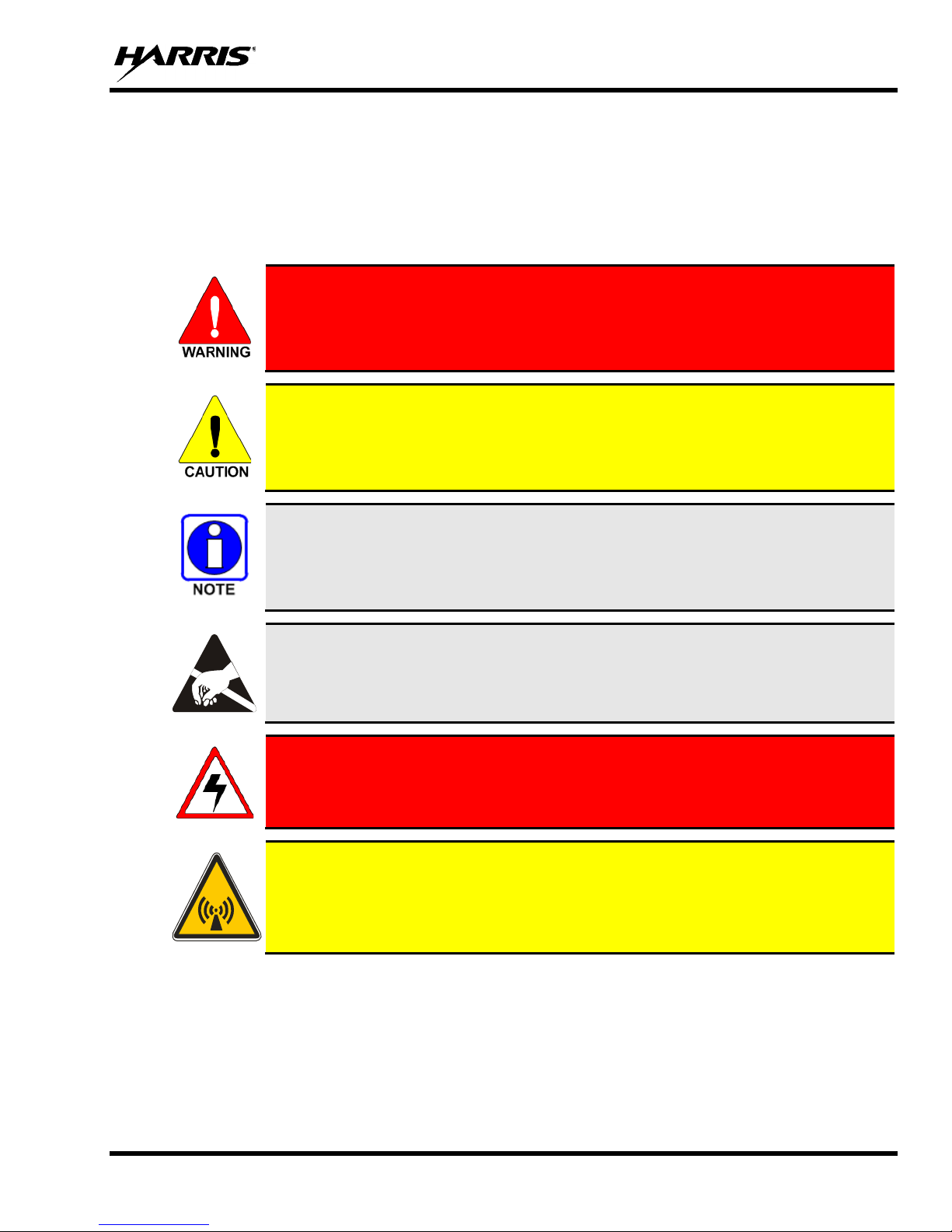
1.2 SAFETY SYMBOL CONVENTIONS
The following conventions may be used in this manu al to alert the user to gen eral safety precauti ons that
must be observed during all phases of operation, service, and repair of this product. Failure to comply
with these precautions or with specific warnings elsewhere in this manual violates safety standards of
design, manufacture, and intended use of the product. Harris assumes no liability for the customer's
failure to comply with these standards.
The WARNING symbol calls attention to a pro cedure, practice, or the like, which,
if not correctly performed or adhered to, could result in personal injury. Do not
understood or met.
The CAUTION symbol calls attention to an operating proced ure, practice, or the like,
which, if not performed correctly or adhered to, could result in a risk of danger, damage
to the equipment, or severely degrade the equipment performance.
The NOTE symbol calls a
system performance or clarify a process or procedure.
The ESD symbol cal ls attenti on to procedures, practices, or t he like, which could expose
equipment to the effects of Electro-Static Discharge. Proper precautions must be taken
to prevent ESD when handling circuit modules.
The electrical hazard symbol is a WARNIN G indicating there may be an electrica l
shock hazard present.
This symbol indicates the presence of a potential RF hazard.
7
MM-018623-001, Rev. D
IS DESIGNED FOR AND
USED ONLY IN THE COURSE OF EMPLOYMENT BY INDIVIDUALS
AWARE OF THE HAZARDOUS RF ENERGY AND THE WAYS TO
IS TO
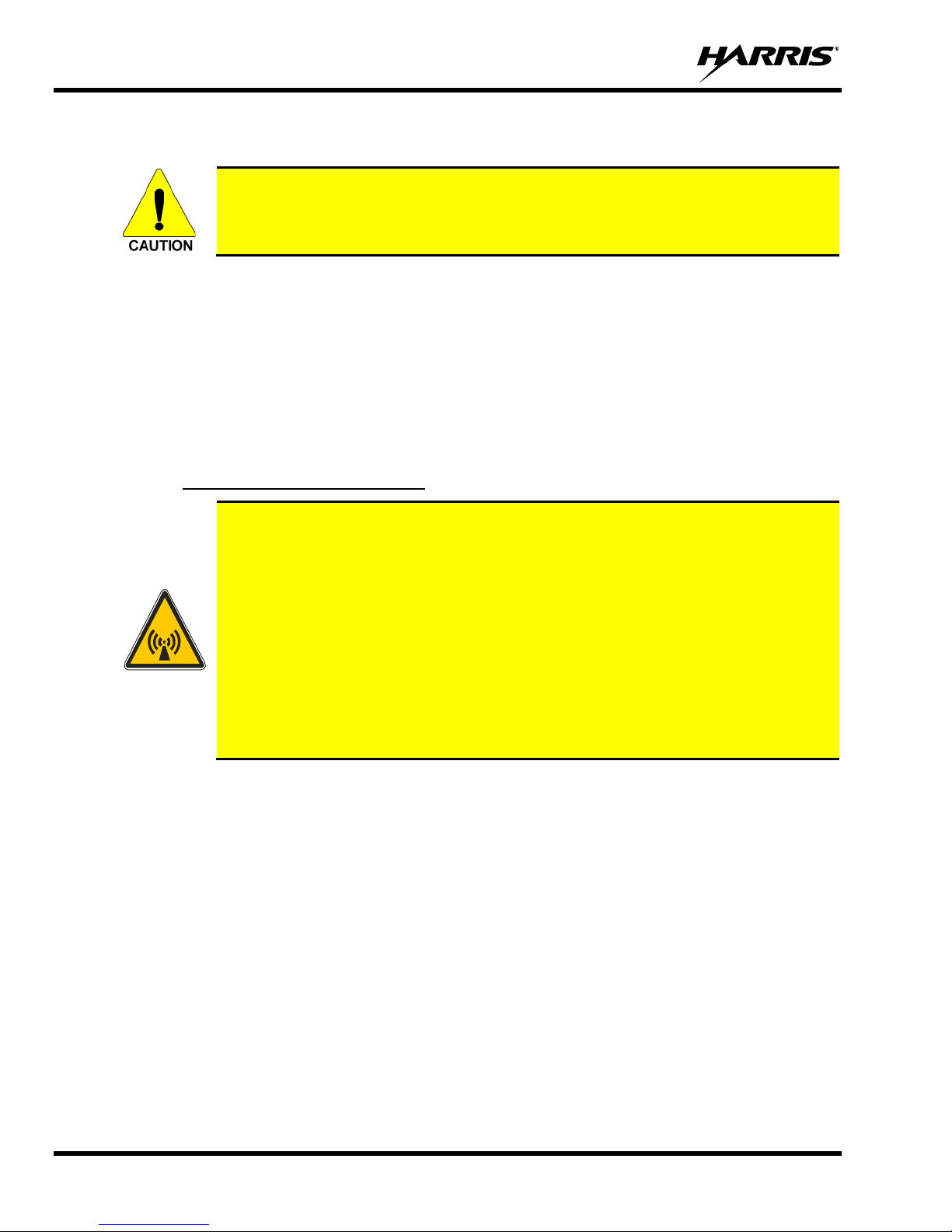
1.3 RF ENERGY EXPOSURE INFORMATION
To ensure that exposure to RF electromagnetic energy is within the FCC allowable
limits for occupational use, always adhere to the following guidelines:
DO NOT operate the SG5300 without a proper antenn a attached, as this may damage the SG5300 and may also
cause the FCC RF exposure limits to be exceeded. A proper antenna is the antenna supplied with this SG5300 by
Harris Corporation or an antenna specifically authorized by Harris for use with this SG5300.
DO NOT transmit for more than 50% of total RADIO use time (“50% duty cycle”). Transmitting more than 50%
of the time can cause FCC RF exposure complianc e requirements to be exceeded. The SG5300 is transmitting
when the “TX” indicator light is on.
Always transmit using low power when possible.
1.3.1 Safety Training Information
YOUR HARRIS SG5300 GENERATES RF ELECTRO-MAGNETIC ENERGY
DURING TRANSMIT MODE. THIS SG5300
CLASSIFIED AS “OCCUPATIONAL USE ONLY,” MEANING IT MUST BE
MINIMIZE EXPOSURE. THIS STATION IS NOT INTENDED FOR USE BY
THE “GENERAL POPULATION” IN AN UNCONT ROLLED E NVIRONME NT.
IT IS THE RESPONSIBILITY OF THE LICENSEE TO ENSURE THAT THE
MAXIMUM PERMISSIBLE EXPOSURE LIMITS ARE OBSERVED AT ALL
TIMES DURING TRANSMISSION. THE STATION LICENSEE
ENSURE THAT NO BYSTANDERS COME WITHIN THE RADIUS OF THE
LIMITS.
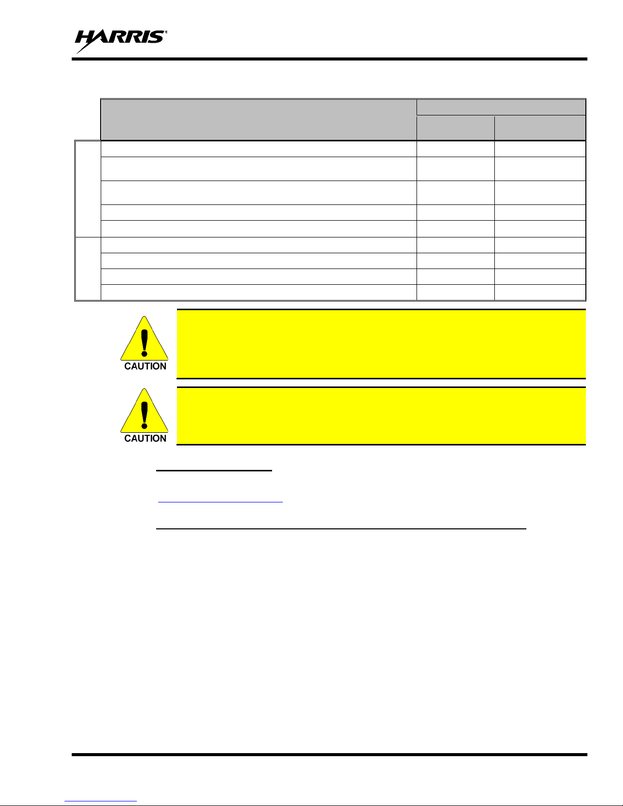
When licensed by the FCC, this device complies with the FCC RF exposure limits when persons are
beyond the MPE radius of the antenna (see Table 1-1). In addition, your Harris SG5300 installation
complies with the following Standards and Guidelines with regard to RF energy and electromagnetic
energy levels and evaluation of such levels for exposure to humans:
FCC OET Bulletin 65 Edition 97-01 Supplement C, Evaluating Compliance with FCC Guidelines
for Human Exposure to RADIO Frequency Electromagnetic Fields.
American National Standards Institute (C95.1 – 1992), IEEE Standard for Safety Levels with
Respect to Human Exposure to RADIO Frequency Electromagnetic Fields, 3 kHz to 30 0 GHz.
American National Standards Institute (C95.3 – 1992), IEEE Recommended Practice for the
Measurement of Potentially Hazardous Electromagnetic Fields – RF and Microwave.
8
MM-018623-001, Rev. D
Minimum Safe Distance (cm)
Controlled
Environment
Uncontrolled
Environment
AN-225001-001 3 dBd (5.15 dBi) dual band roof mount antenna
20
20
AN-225001-002 3 dBd (5.15 dBi) dual band elevated feed poi nt
antenna
20
20
AN-225001-003 3 dBd (5.15 dBi) dual band elevated feed poi nt
antenna
20
20
AN-225001-004 2 dBd (4.15 dBi) low profile antenna
20
25
AN-225001-005 5 dBd (7.15 dBi) dual band roof mount antenna
20
20
AN-225005-001 3 dBd (5.15 dBi) roof mount antenna
20
20
AN-225005-002 3 dBd (5.15 dBi) elevated feed roof mount antenna
20
20
AN-225005-003 3 dBd (5.15 dBi) elevated feed roof mount antenna
20
20
AN-225005-004 2 dBd (4.15 dBi) low profile antenna
20
25
Table 1-1: MPE Table
Antenna
800 MHz
900 MHz
To ensure that your exposure to RF electromagnetic energy is within the FCC
allowable limits for occupational use, do not operate the station in a manner that
would create an MPE distance in excess of t hat allowable by the FCC.
Changes or modifications not expressly approved by Harris could void the user’s
authority to operate the equipment.
1.3.2 Contact Information
For additional information on exposure requirements or other information, contact Harris at 1-800-5287711 or at http://www.pspc.harris.com
.
1.3.3 Occupational Safety Guidelines and Safety Training Information
To ensure bodily exposure to RF electromagnetic energy is within the FCC allowable limits for
occupational use. Always adhere to the following basic guidelines:
• The SG5300 should only be used for necessary work-related co mmunications.
• The SG5300 should only be used by authorized and trained personnel.
• Do not attempt any unauthorized modification to the SG5300. Changes or modifications to the
SG5300 may cause harmful interference and/or cause it to exceed FCC RF exposure limits. Only
qualified personnel should service the SG5300.
• Always use Harris authorized accessories (antennas, control heads, speakers/mics, etc.). Use of
unauthorized accessories can cause the FCC RF exposure compliance requirements to be exceeded.
The information listed above provides the user with information needed to make him or her aware of a RF
exposure, and what to do to assure that this SG5300 operates within the FCC exposure limits of this radio.
9
MM-018623-001, Rev. D
CONFORMS TO ALL APPLICABLE REGULATIONS AND CODES,
1.4 DIVISION 2 NON-INCENDIVE PROTECTION
Division 2 Non-Incendive Protection is available as an option when ordering the SG5300-900, 900 MHz
unit. When ordered with this option, this apparatus is suitable for use in hazardo us locations as defined
by the National Electrical Code (NEC) as Class I, Division 2, groups A, B, C, and D applications.
Specific torque values for antenna and cable connections (further discussed in the installatio n section of
this manual) are required to conform to this rating. When no serial cable connection is present, a
protective cover (supplied with the option) is required.
When installing electrical equip ment in hazardous areas, it is important to be familiar with the National
Electrical Code rules, the National Fire Protection Agency regulations, all local codes, and the
specifications of your underwriter for hazardous areas. Ensure those who are responsible for installing the
equipment are properly qualified for the work and are informed of all necessary information and
specifications.
WARNING: EXPLOSION HAZARD.
DO NOT DISCONNECT WHILE THE CIRCUIT IS LIVE OR UNLESS THE
AREA IS KNOWN TO BE FREE OF IGNITIBLE CONCENTRATIONS.
Always follow all NEC, NFPA, and local codes when installing this equipment in
hazardous areas. Knowledgeable personnel, who are familiar with national and
local codes, must supervise hazardous area equipment installations.
Harris is not responsible for the installation of your hazardous area equipment.
YOU MUST ENSURE THAT THE INSTALLATION OF THIS EQUIPMENT
INCLUDING, BUT NOT LIMITED TO, THOSE OF THE NATIONAL FIRE
PROTECTION ASSOCIATION, THE NAT IONAL ELECTRICAL CODE, AND
ANY APPLICABLE LOCAL CODES. Important information regarding
installation of the SG5300 is included in this manual; however, should not be
regarded as the complete set of information required to safely install electrical
equipment in hazardous areas. Always use qualified technicians and knowledgable
personnel who are familiar with national and local codes to install such equipment
in hazardous areas.
This apparatus is suitable for use in Class I, Division 2 groups A, B, C, and D.
10
MM-018623-001, Rev. D
2 INTRODUCTION
2.1 ABOUT THIS MANUAL
This manual is written for the communications professional responsible for installing and maintaining the
SG5300 Data Modem.
Some features found in this manual require the SG5300 operating software version to be
R21A or later.
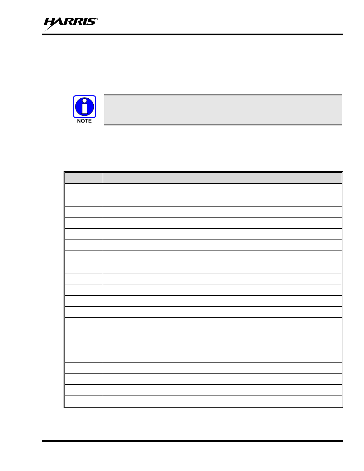
2.2 GLOSSARY OF TERMS
The following table is a list of terms used in this manual.
Table 2-1: Glossary of Terms
TERM DEFINITION
AWG American Wire Gauge
DNP3 Distributed Network Protocol
ICMP Internet Control Message Protocol
IEEE Institute of Electrical & E l ect ronics Engineers
LED Light Emitting Diode
LCL Licensed Channel List
MES Mobile End System
NEC National Electrical Code
NEMA National Electrical Manufactures Association
NFPA National Fire Protection Association
PPP Point to Point Protocol
SDO Site Deployment Order
SLIP Serial Line Internet Protocol
SNMP Simple Network Management Protocol
TAC Technical A ssistance Center
TFTP Trivial File Transfer Protocol
TRU Remote Terminal Unit
UDP User Datagram Protocol
VIDA Voice, Interoperability, Data, and Access
WAN Wide Area Network
11

MM-018623-001, Rev. D
3 DESCRIPTION
The SG5300 Data Modem is part of the OpenSky® suite of products which delivers very high capacity,
end-to-end digital data communication. The small and lightweight unit is housed in a plastic case suitable
for mounting indoors or in a National Electrical Manufactures Ass ociation (NEMA) approved enclosure.
It is designed to provide reliable, secure, and cost effective data communications to and from remote
locations.
Options are available which make the SG5300-900 an apparatus suitable for use i n hazardous locations.
When ordered with these options, the SG5300-900 meets the requirements defined by the National
Electrical Code (NEC) for use in Class I, Division 2, groups A, B, C, and D applications.
3.1 MULTIPLE APPLICATIONS
The SG5300 is suitable for a wide range of ap plications. The su bstantial cov erage of an OpenSky private
wireless network means that the SG5300 can b e useful to collect or distribute data messag es in locations
where other wireless technolo gies are either not avail able or unreliable. Utilities will find it an excellent
means of communication with line reclosers, capacitor banks, and other devices on the grid.
Transportation applications include automated signs, bus stop kiosks, and connection with remote traffic
flow and weather sensors. Public safety agencies may use it to send alarms for public notification of
severe weather, emergencies, or for a host of other applications.
12
Figure 3-1: SG5300 Data Modem

MM-018623-001, Rev. D
Figure 3-2: SG5300 System Application
The SG5300 provides a choice of Ethernet (RJ45) or Serial (DB9) interface to remote terminals. Its
3-Watt RF output makes it a compact and cost-effective wi reless li nk that can easily fi t alongside Re mote
Terminal Units (RTUs) and other devices.
The SG5300 is capable of interfacing to RTUs via an Ethernet 10/100Base-T interface port or
TIA/EIA-232 Serial interface port. The Ethernet port is capable o f operating as a data interface between
the SG5300 and external devices with MTU size of 1400 bytes or less.
The Serial port is capable of operat ing as the data interface using Serial Line Internet Protocol (SLIP),
Point to Point Protocol (PPP), Packetized Distributed Network Protocol (DNP3), or Serial Tunneling
between the SG5300 and external dev ices (RTUs). The SG5300 is configu red so that the data interface
communicates with either t he Ethernet port or the Serial port, but not both simultaneously. For additional
information, refer to Section 9 for DNP3 or Section 10 for Serial Tunneling.
The Serial port is also used as a maintenance port to configure the RF radio, software loading, and
configuration of the Ethernet port. However, the Serial port is not available for maintenance use while
external devices are connected to the Ethernet port.
3.2 OVER-THE-AIR PROGRAMMING
As an OpenSky radio, the SG5300 benefits from a flexible, software-based design. Features, profiles, and
system updates are software-defined and can be reprogrammed over the air.
3.3 VERSATILE MOUNTING
The SG5300 is designed to be mounted indoors or in a NEMA enclosure.
13

MM-018623-001, Rev. D
4 OPERATION
In-service operation of the SG5300 is completely automatic. Once the unit is properly installed and
configured, local unit operation can be observed by viewing the Status LEDs for proper operation.
After properly installing the unit, operational control and monitoring can be made from the Network
Management Center and the Centralized System Server.
4.1 STARTING THE SG5300
Start the radio operation by following these steps:
1. When installed in hazardous locations, observe all safety requirements for operating such apparatus.
2. Apply DC power to the transceiver.
3. Observe the Status LEDs for the proper indications as defined in Table 4-1.
Figure 4-1: SG5300 Controls and Indicators
14
MM-018623-001, Rev. D
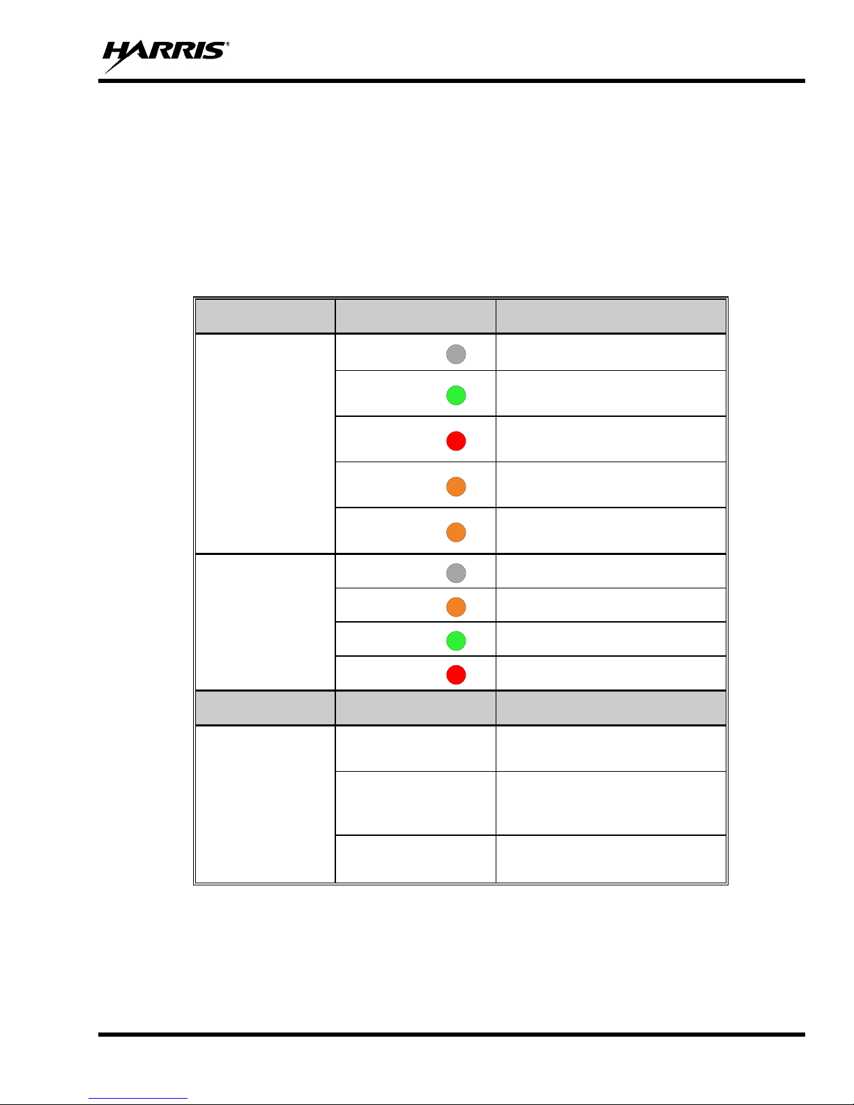
4.2 INDICATORS
The SG5300 RF Radio unit has two tri-color LEDs which indicate its operating status. The Unit Status
LED, located near the power connector, ind icates Power On or Normal Operation (amber or orang e). It
also indicates when the unit is in the Configure Ethernet mode (red) or is booting up (green).
The Radio Status LED, located near th e antenna connector, indicates the operational status o f the radio
section. This LED indicates whether data is being transmitted (red), received (g reen) or other support
functions (orange).
INDICATOR INDICATOR COLOR DESCRIPTION
Table 4-1: Indicators and Controls
OFF
Blinking
GREEN
Radio Status LED
Unit Status LED
CONTROL POSITION DESCRIPTION
Blinking
RED
Blinking
AMBER
Solid
AMBER
OFF
AMBER
GREEN
RED
Ethernet
No Status
Receiving RF Signal
Transmitting RF Signal
Data Registration Failure and/or
Loss of Sync
Offline
No Power Applied
Normal Operation
Booting Up
Configure Ethernet
Selects Ethernet Port for data
interface.
Configuration
Switch (Config)
15
Config Ethernet
Serial
Allows you to configure the
Ethernet port settings using an
RS-232 terminal.
Selects Serial Port for data
interface.
MM-018623-001, Rev. D
5 UNPACKING AND CHECKING EQUIPMENT
Before unpacking, installing, or operating the SG5300, read this section of the manual thoroughly. It
contains detailed unpacking and handling instructions, and safety precautions to protect users and
equipment.
5.1 UNPACKING EQUIPMENT
The SG5300 may be shipped in separate transit packages. The associated cabling and accessories for
each unit, if any, may also be shipped in separate containers.
When unpacking the equipment, check the contents against the packing list. Contact your Harris
representative and the carrier if any discrepancies are noted.
Save the shipping cartons and packing materials in case the equipment needs to be
shipped back to the Harris for service.
5.2 INSPECTING AND INVENTORYING EQUIPMENT
Carefully unpack the equipment and examine each item. If there i s any damage to the equip ment, con tact
the carrier immediately and have th eir representativ e verify the damage. If yo u fail to report the shippin g
damages immediately, you may forfeit any claim against the carrier.
After removal from the carton, examine the SG5300 for broken, damaged, loose, or
missing parts. Examine the RF connector(s), power connector, and ground lug for
cracks, bent or damaged threads, or damage to any paint or seals. If any are noted,
contact the Harris Customer Care center immediately. Any unauthorized attempts to
repair or modify this equipment will void the warranty and could create a safety hazard .
5.3 ITEMS INCLUDED
The following items are included in the SG5300 package:
• RU-019026-800 Radio Unit (800 MHz)
or
• RU-019026-900 Radio Unit (900 MHz)
and
• SG5300 Data Modem Quick Guide (14221-6100-1000)
• Serial Port Protective Cover (Non-Incendi ve rated models)
16

MM-018623-001, Rev. D
5.4 OPTIONS AND ACCESSORIES
MODEL/OPTION
NUMBER
Transceivers
SG5300-800 SG5300, Data Only, 800 MHz
SG5300-900 SG5300, Data Only, 900 MHz
Options
Adds Non-Incendive Rated option to the SG5300-800 or SG5300-900 transceiver
(available only at the time of original sale of equipm ent)
Serial Port Protective Cover (required to m eet Non-Incendive rating)
Antennas
AN-225001-001 764-870 MHz, Dual band 3 dB gain roof mount antenna
AN-225001-002 764-870 MHz, Dual band 3 dB gain elevated feed point antenna
AN-225001-003 764-870 MHz, Dual band 3 dB gain elevated feed point antenna
AN-225001-004 764-870 MHz, Dual band 2 dB gain low profile ant enna
DESCRIPTION
AN-225001-005 764-870 MHz, Dual band 5 dB gain roof mount antenna
AN-225005-001 900 MHz, 3 dB gain roof mount antenna
AN-225005-002 900 MHz, 3 dB gain elevated feed roof mount antenna
AN-225005-003 900 MHz, 3 dB gain elevated feed roof mount anten na
AN-225005-004 900 MHz, 2 dB gain low profile antenna
17

MM-018623-001, Rev. D
6 INSTALLATION
6.1 GENERAL PLANNING
Careful planning and preparation of any installation will always benefit the end result .
1. Always read and follow all installation instructions, local and national building and electrical codes,
and general safety rules.
2. Before beginning the installation, collect information from the Site Deployment Order (SDO) specific
to the site access such as:
• Permission to access the site.
• Important contact names and telephone numbers.
• Location of and directions to the site.
• Keys and/or lock combinations to access the site and equipment shelter (if any), or points of
contact to obtain them.
• Site entry alarm system pass-codes and/or disable keys.
• Information about work practices needed to work safely at the site including, where applicable,
additional work practices required for working in non-incendive areas.
3. Other important information that may or may not be included on the SDO includes:
• Type of mounting—NEMA case, interior wall, etc.
• Drawin g or description of each site showing how and where the equipment is being installed.
• Applicable inspections completed (electrical , local build code, etc.).
• Inst aller must be aware of other transmitters and r eceivers on site that could cause interference to,
or be interfered with, by the equipment. Strong signals from, or to, co-located equipment may
inflict permanent damage to either device.
4. We recommend pre-staging the equipment to become familiar with the specific hardware and cabling,
tooling, and supplies that are needed to complete the installation.
6.2 SITE GROUNDING
Installers should review the recommended grounding procedures in the Site Grounding and Lightning
Protection Guidelines Manual, AE/LZT 123 4618/1 and ensure a suitable ground is install ed between the
SG5300’s ground lug and earth ground. Grounding must also be in compliance with any local and
national electrical codes.
6.3 EQUIPMENT INSTALLATION
Below are the basic steps for installing th e SG5300. In most cases, these steps alone are sufficient to
complete the installation. However, when installed in hazardous locati ons as defin ed by th e NEC as Class
I, Division 2 groups A, B, C, or D, the SG5300 product must include the factory label specifying it meets
the standard and requires additional installation procedures. Read, understand, and follow all instructions,
18
MM-018623-001, Rev. D
B, C, or D, require additional
local codes, must supervise hazardous area equipment installations. Refer to
Notes, Cautions, and Warnings which appear in this and other sections of this manual before beginning
attempting installation.
The 900 MHz unit, SG5300-900, when installed in hazardous locations as defined
by the NEC as Class I, Division 2 groups A,
installation procedures. Read, understand, and follow all instructions, Notes,
Cautions, and Warnings which appear in this and other sections of this manual
before beginning installation.
Always follow all NEC, NFPA, and local codes when installing this equipment in
hazardous areas. Knowledgeable personnel, who are familiar with national and
Section 1.4 for additional information.
WARNING: EXPLOSION HAZARD.
DO NOT DISCONNECT WHILE THE CIRCUIT IS LIVE OR UNLESS THE
AREA IS KNOWN TO BE FREE OF IGNITIBLE CONCENTRATIONS.
1. Mount the SG5300 to a stable surface. Refer to Section 6.4 for dimensions.
2. Connect the RTU equipment to the appropriate data interface co nnector.
(See Section 6.6.4 for Ethernet interface or 6.6.5 for a serial interface.)
Only one data interface connection can be used at a time.
3. Select the interface using the Configuration switch.
4. Connect the SG5300 to a suitable power source (see Section 6.5) which meets the following
requirements:
a. A readily accessible disconnect device shall be incorporat ed external to the equipment.
b. A 1-Amp over-current protection device shall be provided external to the equipment.
5. Install and orient the antenna as required (see Section 6.6.3).
6. Configure the SG5300 as required. Refer to Section 7 for instructions.
The operating frequencies are not set at the factory. Determine the transmitter and
receiver frequencies to be used, and fo llow the programming instructions in Section 7.
6.4 MOUNTING THE SG5300
The SG5300 is typically installed in an outdoor enclosure that protects the unit from weather and where
temperature is not typically controlled. The unit may also be mounted indoors in equipment closets.
19
 Loading...