

Page 1

SEL-1ENC1
Universal Encoder
Installation and Operation Manual
D
Edition B
175-100266-00
Page 2

Page 3

Selenio
SEL-1ENC1
Universal Encoder
Installation and Operation Manual
Edition B
May 2011
Page 4

Harris Corporation
Broadcast
Communications
Transmission
4393 Digital Way
Mason, OH USA 45040
Media & Workflow
9800 South Meridian
d.
Blv
Suite 300
Englewood, CO USA
112
80
Infrastructure &
tworking
Ne
25 Dyas Road
North York, ON
M3B 1V7
Canada
Copyright © 2011, Harris Corporation, 1025 West NASA Boulevard, Melbourne, Florida 32919-0001 U.S.A. All
rights reserved. This publication supersedes all previous releases. No part of this documentation may be reproduced
in any form or by any means or used to make any derivative work without permission from Harris Corporation.
Harris Corporation reserves
the right to revise this documentation and to make changes in content from time to
time without obligation on the part of Harris Corporation to provide notification of such revision or change.
UNITED STATES GOVERNMENT LEGEND If
you are a United States government agency, this documentation and
the software described herein are provided to you subject to the following:
All technical data and compute
r software are commercial in nature and developed solely at private expense.
Software is delivered as “Commercial Computer Software” as defined in DFARS 252.227-7014 (June 1995) or as a
“commercial item” as defined in FAR 2.101(a) and as such is provided with only such rights as are provided by
Harris’ standard commercial license for the Software. Technical data is provided with limited rights only as provided
in DFAR 252.227-7015 (Nov 1995) or FAR 52.227-14 (June 1987), whichever is applicable. You agree not to
remove or deface any portion of any legend provided on any licensed program or documentation contained in, or
delivered to you in conjunction with, this User Guide.
This publication, or any part thereof, may not be r
eproduced in any form, by any method, for any purpose, without
the written consent of Harris Corporation.
Contact Harris Corporation fo
r permission to use materials as well as guidelines concerning foreign language
translation and publication.
Harris Corporation reserves the right to r
evise and improve its products as it chooses. This publication is designed
to assist in the use of the product, as it exists on the date of publication of this manual, and may not reflect the
product at the current time or an unknown time in the future. This publication does not in any way warrant
description accuracy or guarantee the use for the product to which it refers.
The Harris logo and assured communications ar
e registered trademarks of Harris Corporation. D-Series is a
trademark of Harris Corporation. All other trademarks are held by their respective owners.
This user guide was created for the Selenio SEL-1ENC1 pr
Windows is a registered trademark of Micr
osoft Corporation. AMD and Operton are trademarks of Advanced
oduct.
Micro Devices, Inc. Manufactured under license from Dolby Laboratories. Dolby and the double-D symbol are
registered trademarks of Dolby Laboratories. HD-BNC is a trademark of Amphenol Corporation. Java is a
trademark of Sun Microsystems, Inc. or its subsidiaries in the United States and other countries.
All other trademarks are the property of their respective holders.
Publication Date: May 2011
Page 5

Contents
Preface..........................................................................................................................v
Manual Information .......................................................................................................v
Purpose ......................................................................................................................v
Audience ....................................................................................................................v
Revision History ..........................................................................................................v
Writing Conventions ...................................................................................................v
Obtaining Documents ................................................................................................vi
Unpacking/Shipping Information ................................................................................ vi
Unpacking a Product ................................................................................................. vi
Product Servicing .......................................................................................................vi
Returning a Product ................................................................................................... vi
Safety Standards and Compliances ............................................................................ vii
Restriction on Hazardous Substances (RoHS) Compliance .......................................... vii
Waste from Electrical and Electronic Equipment (WEEE) Compliance ......................... vii
Safety Terms and Symbols in this Manual ................................................................ viii
iii
Installation, Operation, and Specifications............................................. 1
Product Description ....................................................................................................... 1
Main Features ................................................................................................................ 1
Video Formats ........................................................................................................... 1
Modules and Softkey Options ..................................................................................... 3
3DTV Functionality .................................................................................................... 4
Front Module ................................................................................................................. 5
Back Modules ................................................................................................................ 6
Pinouts ...................................................................................................................... 7
Signal Flow .................................................................................................................... 8
Installing SEL-1ENC1 Modules ...................................................................................... 9
Removing Selenio Modules ........................................................................................ 10
Front Module .......................................................................................................... 10
Back Module ........................................................................................................... 10
Powering Up a Module ............................................................................................... 11
Upgrade Module Firmware ........................................................................................ 11
Upgrade Failure Instructions .................................................................................... 11
Video Input .................................................................................................................. 12
General ................................................................................................................... 12
Status ...................................................................................................................... 13
Video Compression ..................................................................................................... 14
General ................................................................................................................... 14
Status ...................................................................................................................... 18
Audio Compression 1-8 ............................................................................................... 18
General ................................................................................................................... 18
Status ...................................................................................................................... 24
Copyright © 2011, Harris Corporation
Page 6

SEL-1ENC1
iv
Installation and Operation Manual
AAC ........................................................................................................................ 24
Dolby E .................................................................................................................... 25
Audio Metadata ....................................................................................................... 25
Transport Stream Mux ................................................................................................ 27
General ....................................................................................................................27
MPEG Parameters Main Program ............................................................................. 28
SI Parameters ........................................................................................................... 28
ASI Output ...............................................................................................................29
ASI Status ................................................................................................................ 29
IP Encapsulation .......................................................................................................... 29
Main Program IP ...................................................................................................... 29
Main Program IP Status ............................................................................................ 29
IP LANs .........................................................................................................................30
General ....................................................................................................................30
Data Services ............................................................................................................... 30
Status ......................................................................................................................30
Ext Data ...................................................................................................................30
VBI ...........................................................................................................................30
Field 1 and 2 Line x Function .................................................................................... 30
VBI Status ................................................................................................................ 32
Ancillary Data ..........................................................................................................32
Ancillary Status ........................................................................................................35
Close Caption .......................................................................................................... 35
AFD .........................................................................................................................36
KLV ..........................................................................................................................37
Teletext and OP-47 .................................................................................................. 37
Splice .......................................................................................................................38
Timecode .................................................................................................................38
GPIx ..............................................................................................................................39
GPI x Function ..........................................................................................................39
GPI x State ............................................................................................................... 39
Serial Data .................................................................................................................... 39
Miscellaneous .............................................................................................................. 39
Name .......................................................................................................................39
Laser Safety for Fiber Optic Back Modules ................................................................ 40
Precautions for Enclosed Systems .............................................................................40
Precautions for Unenclosed Systems ......................................................................... 40
Label .............................................................................................................................41
Inspecting and Cleaning Fiber Optic Connections .................................................... 41
Important Points ...................................................................................................... 42
Inspection and Cleaning Procedure .......................................................................... 43
Specifications ............................................................................................................... 44
ASI Output ...............................................................................................................44
Audio Compression Specifications ............................................................................ 44
Video Input Specifications ........................................................................................ 45
Video Output Specifications ..................................................................................... 46
Index........................................................................................................................... 49
Copyright © 2011, Harris Corporation
Page 7

Preface
Manual Information
v
Purpose
Audience
Revision
Conv
History
Writing
entions
This manual details the features, installation, operation, maintenance, and specifications for
the SEL-1ENC1 Universal Encoder.
This manual is written for engineers, technicians, and operators responsible for installation,
setup, maintenance, and/or operation of the SEL-1ENC1
Table 1-1 Revision History of Manual
Edition Date Comments
A March 2011 Initial release
B May 2011 Installation modifications
To enhance your understanding, the authors of this manual have adhered to the following
text conventions:
Table 1-2 Writing Conventions
Term or
Convention
Bold Indicates dialog boxes, property sheets, fields, buttons, check boxes,
Description
list boxes, combo boxes, menus, submenus, windows, lists, and
selection names
Universal Encoder.
Italics Indicates E-mail addresses,
the first instances of new terms and specialized words that need
emphasis
CAPS Indicates a specific key on the keyboard, such as ENTER, TAB, CTRL,
ALT, or
Code Indicates variables or comma
something you type into a field
> Indicates the direction of navigation through a hierarchy of menus and
w
DELETE
indows
the names of books or publications, and
nd-line entries, such as a DOS entry or
Copyright © 2011, Harris Corporation
Page 8

SEL-1ENC1
vi
Installation and Operation Manual
riting Conventions
Description
elsew
here
Indicates important information that helps to avoid and troubleshoot
pr
oblems
Obtaining
Documents
Table 1-2 W
Term or
Convention
hyperlink Indicates a jump to another location within the electronic document or
Internet address Indicates a jump to a website or URL
Product support documents can be viewed or downloaded from our website. Alternatively,
contact your Customer Service representative to request a document.
Unpacking/Shipping Information
Unpacking a
Product
This product was carefully inspected, tested, and calibrated before shipment to ensure years
of stable and trouble-free service.
Product
Servicing
Returning a
Product
1 Check
2 Con
3 Contact your de
4 Co
5 Remo
equipment for any visible damage that may have occurred during transit.
firm that you have received all items listed on the packing list.
aler if any item on the packing list is missing.
ntact the carrier if any item is damaged.
ve all packaging material from the product and its associated components before you
install the unit.
Keep at least one set of original packaging, in the event that you need to return a product
r servicing.
fo
Except for firmware upgrades, SEL-1ENC1 modules are not designed for field servicing. All
hardware upgrades, modifications, or repairs require you to return the modules to the
Customer Service center.
In the unlikely event that your product fails to operate properly, please contact Customer
Service to obtain a Return Authorization (RA) number, and then send the unit back for
servicing.
Keep at least one set of original packaging in the
for service. If the original package is not available, you can supply your own packaging as
long as it meets the following criteria:
event that a product needs to be returned
The packaging must be able to withstand the product’s weight.
The product must be held rigid within the packaging.
There must be at least 2 in. (5 cm) of space between the product and the container.
The corners of the product must be protected.
Copyright © 2011, Harris Corporation
Page 9

Ship products back to us for servicing prepaid and, if possible, in the original packaging
material. If the product is still within the warranty period, we will return the product prepaid
after servicing.
Safety Standards and Compliances
The Selenio series safety manual is shipped in the Harris Infrastructure and Networking
Documentation and Product Resources DVD, and can be downloaded from our website.
Restriction on Hazardous Substances (RoHS) Compliance
Directive 2002/95/EC—commonly known as the European Union (EU) Restriction on
Hazardous Substances (RoHS)—sets limits on the use of certain substances found in
electrical and electronic equipment. The intent of this legislation is to reduce the amount of
hazardous chemicals that may leach out of landfill sites or otherwise contaminate the
environment during end-of-life recycling. The Directive, which took effect on July 1, 2006,
refers to the following hazardous substances:
Installation and Operation Manual
SEL-1ENC1
vii
Lead (Pb)
Mercury (Hg)
Cadmium (Cd)
Hexavalent Chromium (Cr-V1)
Polybrominated Biphenyls (PBB)
Polybrominated Diphenyl Ethers (PBDE)
According to this EU Directive, all products sold
in the European Union will be fully
RoHS-compliant and “lead-free.” (See our website for more information on dates and
deadlines for compliance.) Spare parts supplied for the repair and upgrade of equipment
sold before July 1, 2006 are exempt from the legislation.
Equipment that complies with the
EU directive will be marked with a RoHS-compliant emblem, as shown in Figure P-1.
Figure P-1 RoHS Compliance Emblem
Waste from Electrical and Electronic Equipment (WEEE) Compliance
The European Union (EU) Directive 2002/96/EC on Waste from Electrical and Electronic
Equipment (WEEE) deals with the collection, treatment, recovery, and recycling of electrical
and electronic waste products. The objective of the WEEE Directive is to assign the
responsibility for the disposal of associated hazardous waste to either the producers or users
of these products. As of August 13, 2005, the producers or users of these products were
required to recycle electrical and electronic equipment at end of its useful life, and may not
dispose of the equipment in landfills or by using other unapproved methods. (Some EU
member states may have different deadlines.)
Copyright © 2011, Harris Corporation
Page 10
SEL-1ENC1
viii
Installation and Operation Manual
In accordance with this EU Directive, companies selling electric or electronic devices in the
EU will affix labels indicating that such products must be properly recycled. (See our website
for more information on dates and deadlines for compliance.) Contact your local Sales
representative for information on returning these products for recycling. Equipment that
complies with the EU directive will be marked with a WEEE-compliant emblem, as shown in
Figure P-2.
Safety Terms
and Symbols
in this
Manual
Figure P-2 WE
This product manual uses the following safety terms and symbols to identify certain
conditions or practices. See page 40 and the Safety Instructions
more information.
WARNING
Statements identifying cond
life. High voltage is present.
CAUTION
Statements identifying con
or other property.
EE Compliance Emblem
and Standards Manual for
itions or practices that may result in personal injury or loss of
ditions or practices that can result in damage to the equipment
Copyright © 2011, Harris Corporation
Page 11

Installation, Operation, and Specifications
Product Description
SEL-1ENC1 modules provide MPEG-2 and H.264 compression of digital video and audio,
with a variety of common compression algorithms for up to 8 stereo pairs of audio, and
processing of associated VBI and VANC data.
1
Main Features
Video Formats
The SEL-1ENC1 supports either sta
formats and a full range of North American and European formats. In addition, the module
also provides a reduced-resolution compressed stream output, which can be used to support
picture-in-picture requirements in IPTV deployments, or for stream monitoring requirements
in network deployments.
A variety of audio compression options are available, including Dolby
MPEG-1 layer 2 AAC-HE, HE-AAC, AAC-LC, HE-AAC, and Dolby E. All audio can be
presented to the encoder as embedded on the SDI, or as separate AES inputs.
Supports the following formats:
1080p/59.94, 1080p/50 - SMPTE424/235 Level A and B
1080i/29.97, 1080i/25 - SMPTE292
720p/59.94, 720p/50 - SMPTE292
480i/29.97 - SMPTE259
576i/25 - SMPTE259
Supports a primary SD/HD encoded stream (except with 1080p60) and secondary
stream encoded at lower resolutions for mobile, picture-in-picture or monitoring
Supports the following coding formats:
H.264 high profile @ up to L4.2 (62.5 Mb/s max)
H.264 restricted to main profile @ up to L4.2
H.264 restricted to baseline profile @ up to L1.3
MPEG-2 422 profile @ up to high level (62.5 Mb/s max)
MPEG-2 restricted to main profile @ up to high level
ndard-definition (SD) or high-definition (HD) SDI video
®
Digital (AC-3) 2.0,
Copyright © 2011, Harris Corporation
Page 12

SEL-1ENC1
2
Installation, Operation, and Specifications
Supports the following reduced horizontal resolutions:
Supports the following reduced resolutions:
Supports video pre-processing:
Audio Input
Supports up to 8 audio encoder engines
VANC processing
VBI processing
Data Input
1920 - 1440, 1280, 960
1280 - 960, 640
720 - 704, 640, 544, 528, 480, 352
CIF (352x240/288)
QVGA (320x240 [4:3] 320x180 [16:9])
SQVGA (160x120 [4:3] 160x90 [16:9])
M/H (416x240 [letterbox for 4:3])
Inverse telecine
Motion compensated temporal filtering (MCTF)
De-blocking filter
8 (High-Density) HD-BNC
Embedded audio from the SDI video input
MPEG-1 Layer 2
Dolby Digital (AC-3)
AAC-LC (MPEG-2 and MPEG-4)
HE-AAC V1 (SBR) and V2 (Parametric Stereo)
Dolby E
SMPTE 302
VANC passthrough (SMPTE 2038) up to 2K words per field
EIA-608/708 closed captioning
AFD
DVITC time code
OP47 teletext
Audio metadata
EIA-608 closed captioning
WSS signaling
WST teletext
VITC time code
AMOL-48 or AMOL-96
VPS data
Closed captions from IP/UDP
GPI triggers from back module
Serial data from back module
TM
connectors on the rear connector board for audio input
Copyright © 2011, Harris Corporation
Page 13

Modules and Softkey Options
Table 1-1 Module Descriptions
Product Description
SEL-1ENC1-EES MPEG-2/H.264 Standard Encoder hardware;
includes video coding, up to four stereo pairs of audio compression, single back
odule with (High-Density) HD-BNC connectors for SDI in/out, ASI out, AES
m
(unbalanced) in, and socket/plug for GPI in/out and serial data connections (software
model key must be selected to enable functions)
SEL-1ENC1-OES MPEG-2/H.264 Standard Encoder hardware;
includes video coding, up to four stereo pairs of audio compression, single back
odule with SFP input (SFP module ordered separately), (High-Density) HD-BNC
m
connectors for SDI in/out, ASI out, AES in (unbalanced), socket/plug for GPI in/out and
serial data connections (software model key must be selected to enable functions)
Installation and Operation Manual
SEL-1ENC1
3
Table 1-2 Module Types
Product Description
SEL-SK-EN-ATSC-HD Software model key for ENC1 - ATSC, support
to four channels of AC-3 audio
SEL-SK-EN-ATSC-MBL Software model key for ENC1 - ATSC MH,
single channel of HE-AAC V2 audio
SEL-SK-EN-ATSC-SD Software model key for ENC1 - ATSC, supporting
channels of AC-3 audio
SEL-SK-EN-C-1080P Software model key for ENC1 - Contribution, supporting MPEG-2 SD, 4:2:0 and 4:2:2
pr
ofiles, H.264 SD High and Main profile and 3G 1080P, up to four channels of
MPEG-1, AC-3 2.0, AAC-LC, HE-AAC V1 and V2 audio
SEL-SK-EN-C-PRO-HD Software model key for ENC1 - Contribution, supporting MPEG-2 HD/SD, 4:2:0 and
2:2 profiles, H.264 HD/SD High and Main profile, up to four channels of MPEG-1,
4:
AC-3 2.0, AAC-LC, HE-AAC V1 and V2 audio
SEL-SK-EN-C-PRO-SD Software model key for ENC1 - Contribution, supporting MPEG-2 SD, 4:2:0 and 4:2:2
ofiles, H.264 SD High and Main profile, up to four channels of MPEG-1, AC-3 2.0,
pr
AAC-LC, HE-AAC V1 and V2 audio
SEL-SK-EN-DVB-HD Software model key for ENC1 - DVB supporting MPEG-2 SD/HD, 4:2:0, and up to four
nels of MPEG-1 audio
chan
SEL-SK-EN-DVB-MBL Software model key for ENC1 - DVB Mobile, supporting H.264 mobile video, and a
sin
gle channel of HE-AAC V2 audio
ing MPEG-2 SD and HD 4:2:0 video, up
supporting H.264 mobile video, and a
MPEG-2 SD 4:2:0 video, up to four
SEL-SK-EN-DVB-SD Software model key for ENC1 - DVB, supporting MPEG-2 SD, 4:2:0, and up to four
chan
nels of MPEG-1 audio
SEL-SK-EN-IPTV-HD Software model key for ENC1 - IPTV, supporting H.264 HD Main profile, and a single
channel
SEL-SK-EN-IPTV-SD Software model key for ENC1 - IPTV, supportin
channel of MPEG-1 or AAC-LC audio
of MPEG-1 or AAC-LC audio
g H.264 SD Main profile, and a single
Copyright © 2011, Harris Corporation
Page 14

SEL-1ENC1
4
Installation, Operation, and Specifications
Table 1-2 Module T
ypes (Continued)
Product Description
SEL-SK-EN-ISDB-HD Software model key for ENC1 - ISDB-Tb, suppo
rting MPEG-2 SD/HD, 4:2:0, and up to
four channels of MPEG-1, AAC-LC, HE-AAC V1 and V2 audio
SEL-SK-EN-ISDB-MBL Software model key for ENC1 - ISDB-Tb Mobile,
supporting H.264 mobile video, and
a single channel of HE-AAC V2 audio
SEL-SK-EN-ISDB-SD Software model key for ENC1 - ISDB-Tb, su
pporting MPEG-2 SD, 4:2:0, and up to
four channels of MPEG-1, AAC-LC, HE-AAC V1 and V2 audio
Table 1-3 Softkey Options
Product Description
SELOPT-SK-EN-AAC Software keyed option for AAC
SELOPT-SK-EN-AUD4 Software keyed option for addit
audio on 4 stereo pairs
ional 4 stereo pairs of audio available on-board
SELOPT-SK-EN-DDE Software keyed option for support of Dolby Digital (AC-3) 5.1 (uses 3 existing stereo
pairs of
audio)
SELOPT-SK-EN-H264 Software keyed option for H.264 encoding, 4:2:0, main and high profile
SELOPT-SK-EN-PRE Software keyed option for pr
e-processing video enhancements for DTH applications
SELOPT-SK-EN-S302 Software keyed option to support for up to 8 stereo pairs of SMPTE-302 pass-through
au
dio
Table 1-4 SFP Receiver Option
Product Quantity Description
OP+SFP+RR 1 Dual PIN
receiver with pathological support for baseband video
3DTV Functionality
The SEL-1ENC1 transports 3DTV signals using the standard shown in Tab l e 1-5.
Table 1-5 SDTV Compatibility
Picture
Quality
Definition
Half 1.5 Gb/s 3D
(SMPTE 292M)
Number of
nections
Con
1 1/2 resolution or better
3DTV Standard Use
Distribution
(many variants)
Copyright © 2011, Harris Corporation
Page 15

Front Module
Installation and Operation Manual
SEL-1ENC1
5
Figure 1-1 SEL-1ENC1 Front Module
Copyright © 2011, Harris Corporation
Page 16
SEL-1ENC1
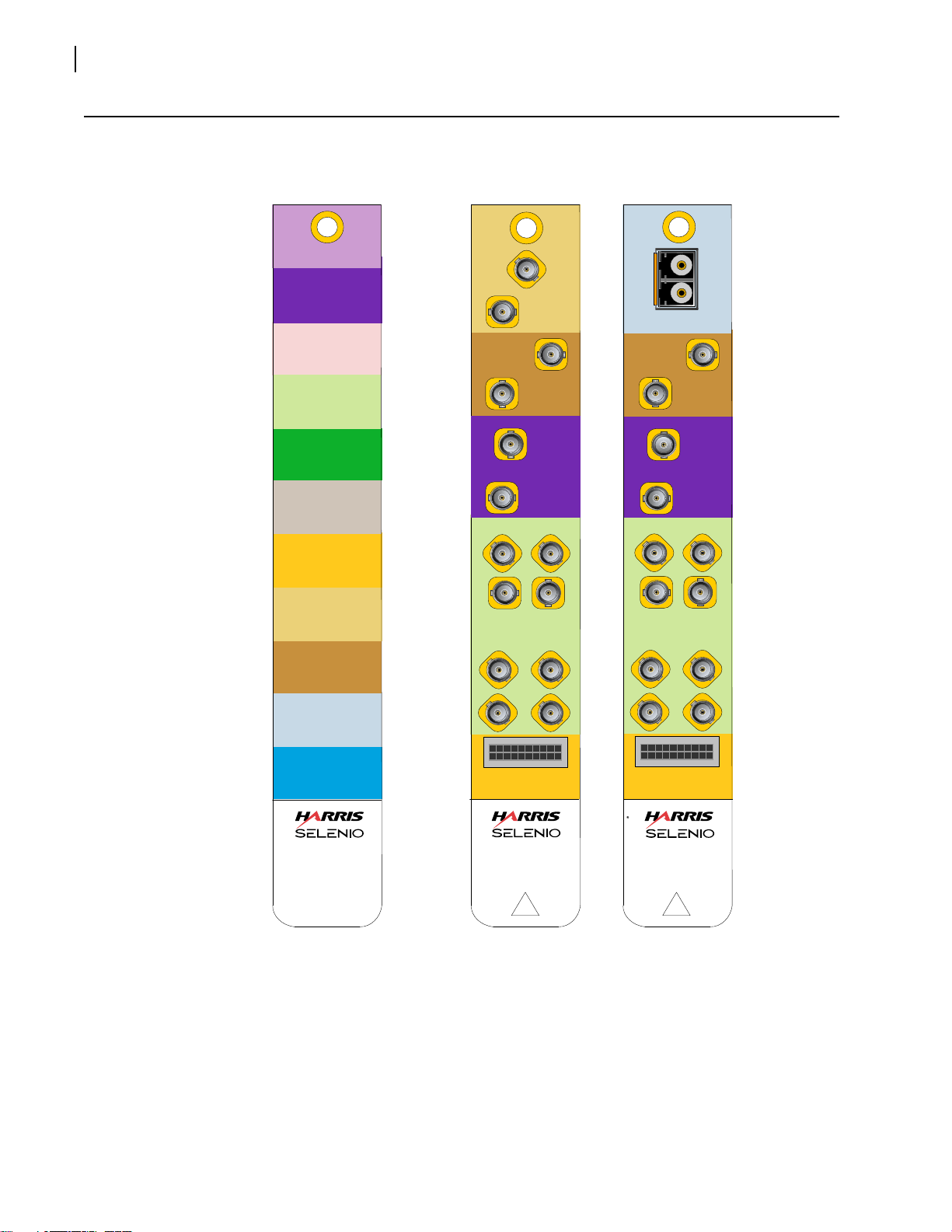
Back Modu le
Color Palette Card
SDI Tx
AUDIO IN
AUDIO OUT
SD I IN
SDI OUT
ASI OUT
AS I IN
MISCELLANEOUS
AUDIO IN/OUT
AS I IN/OUT
SDI Rx
F
SEL-BM-ENC-EES
Enco der
ENC
2
1
20
19
SDI
IN
SEL-BM-ENC-EE S
AES
IN
NOT
USED
78
56
34
1
2
GPI / S ER IAL
1
2
ASI
OUT
SDI
OUT
2
1
G
SEL-BM-ENC-OES
Enco der
ENC
2
1
20
19
AES
IN
SDI
Rx
SDI
OUT
1
2
2
SEL-BM-ENC-OES
ASI
OUT
1
2
7
8
56
34
1
2
GPI / S ER IAL
1
6
Installation, Operation, and Specifications
Back Modules
Figure 1-2 Selenio Color Scheme and Encoder Back Modules
Copyright © 2011, Harris Corporation
Page 17

Pinouts
2
1
20
19
Figure 1-3 GPI/Serial Connector Pinouts
Installation and Operation Manual
SEL-1ENC1
7
Table 1-6 GPI/Serial P
Pin Function
1 GPI Out 1
2 GPI Out 2
3 GPI Out 3
4 GPI Out 4
5 GPI In 1
6 GPI In 2
7 GPI In 3
8 GPI In 4
9 D-Ground
10 D-Ground
11 RS-422 Port 2 Rx+
12 RS-422 Port 2 Rx-
(RS-232 Port 2 Rx)
13 RS-422 Port 2 Tx+
14 RS-422 Port 2 TX-
(RS-232 Port 2 Tx)
inouts
15 D-Ground
16 D-Ground
17 RS-422Port 1 Rx+
18 RS-422 Port 1 Rx-
(RS-232 Port 1 Rx)
19 RS-422Port 1 Tx+
20 RS-422 Port 1 Tx-
(RS-232 Port 1 Tx)
Copyright © 2011, Harris Corporation
Page 18
SEL-1ENC1
EXT SDI
(EXT SDI)
Video
Input
Video
Compression
1 2 3 4
5 6 7 8
Audio Compression
Data
Services
GPI
Serial
Misc
CTR SDI
EXT SDI 1
EXT ASI 1
EXT GPI 1-4
CTR SDI
(INT SDI)
EXT ASI 2
CXN
EXT IP
Transport
Stream Mux
IP
Encapsulation
IP LA N
EXT ASI 1-8
2
1
20
19
EXT Serial 1
EXT IP MGMT
De-Embed
EXT SDI 2
EXT Serial 2
SDI Rx
(EX T SD I)
Video
Input
Video
Compression
Data
Services
GPI
Serial
Misc
CTR SDI
EXT SDI 1
EXT ASI 1
CTR SDI
(INT SDI)
EXT ASI 2
CXN
EXT IP
Transport
Stream Mux
IP
Encapsulation
IP LA N
EXT ASI 1-8
EXT IP MGMT
De-Embed
EXT SDI 2
EXT GPI 1-4
2
1
20
19
EXT Serial 1
EXT Serial 2
1
2
3 4
5 6 7 8
Audio Compression
8
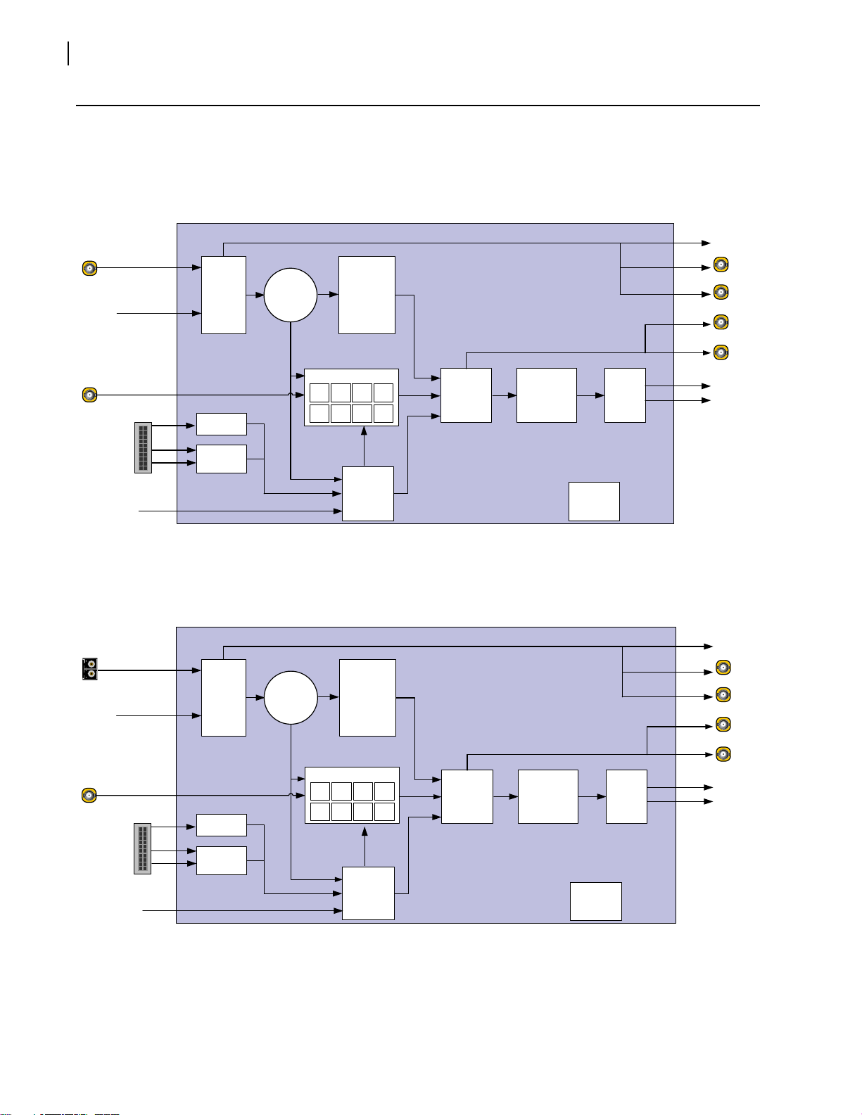
Installation, Operation, and Specifications
Signal Flow
Figure 1-4 SEL-1ENC1 Block Diagram (EES Version)
Figure 1-5 SEL-1ENC1 Block Diagram (OES Version)
Copyright © 2011, Harris Corporation
Page 19

Installing SEL-1ENC1 Modules
Align pin into
guide hole
14.
10.
9.
8.
7.
6.
5.
4.
3.
2.
1.
13.
12.
11.
You can insert a Selenio module into a frame with the power supply turned on or off.
Follow this procedure:
emove a blank back module from the frame, saving the blank back modules and their
1 R
captive screws for future configurations.
2 At
tach the new back module to the empty slot, using the mounting screws provided.
Align the back module’s pin into the guide hole, and ensure that the EMI gaskets
sepa
rating the back modules remain in place during the installation. The EMI gaskets fit
tightly. To ease the installation of back modules, gradually press each back module into
place from the left side to the right side.
Installation and Operation Manual
SEL-1ENC1
9
Figure 1-6 Installing Ba
3 Apply la
4 Pri
nt out this page and write down the placement of the back modules in the diagram
below (back modules appear on the reverse side when viewed from the front).
Figure 1-7. Writing Space for Ide
ck Modules
bels to the back module, if these are supplied separately.
ntifying Back Modules
Copyright © 2011, Harris Corporation
Page 20

SEL-1ENC1
1. Pull down
to unlock the
extractor.
Extractor lock
2. Slide the
module out of
the slot.
Flat support post
rotates for module
insertion and removal
10
Installation, Operation, and Specifications
CAUTION:
Do not mix and match back and front modules. Th
back module of the same product.
e front module must mate with a
5 Op
en the front panel and then slide the correct front modules into the slots that match the
back modules.
6 Push
the module until it seats properly, ensuring the edge of the module is flush with the
edge of the module guides, and the square extractor handle clicks into its slot.
7 Ins
tall the remaining back and front modules, make all of the necessary rear connections,
and then close the front panel.
CAUTION:
To prevent overheating during frame operation, keep the front panel closed and all
ck module slots covered.
ba
Removing Selenio Modules
Front Module To remove a front module from a Selenio frame, follow this procedure:
1 Op
2 Grasp
3 Usin
en the front panel.
the extractor handle on the module, pulling down slightly.
g the handle, slide the module out of its slot.
Figure 1-8 Remo
4 Clo
se the front panel to ensure proper frame ventilation.
ving a Front Module
Back Module To remove a back module from a Selenio frame, you must first remove the front module.
Then unscrew the back module, and pull it straight out. Cover the opening with a blank
Copyright © 2011, Harris Corporation
back module to ensure proper frame ventilation.
Page 21

Powering Up a Module
Move Switch 1
to the On
position for
failsafe
operation
The SEL-1ENC1 is ready for use when its parameters appear in the Selenio UI. The power
consumption of a SEL-1ENC1 module is 45 W.
Upgrade Module Firmware
All module firmware upgrades are activated in the frame controller section of the Selenio
user interface. Follow this path to find the appropriate parameters: Configuration >
Frame Controller > Configuration tab > Upgrade Firmware.
Installation and Operation Manual
SEL-1ENC1
11
Upgrade
Failure
Instructions
See the Selenio frame ma
In the unlikely event of an upgrade failure for the
Instructions of this manual.
The SEL-1ENC1 includes one user-configurable DIP switch array (SW1), located at the card
edge next to the extractor. In normal operation, all four switches are in the Off position, set
closest to the card edge. In the unlikely event of corrupted software, you may need to
temporarily change the setting of Switch 1 for the failsafe mode override. You would be
alerted to this problem if a System Recovery Upgrade Required fault was triggered after
an upgrade, and the module had finished rebooting.
stem Recovery Upgrade Required fault is triggered, you should first try using the
If a Sy
alternate firmware (see Activating Alternate Firmware in the Selenio frame manual) and
then attempt the upgrade again. If this second attempt fails, follow these steps to activate
the failsafe mode:
1 Re
move the SEL-1ENC1 module from the frame and then push Switch 1 to the On
position.
nual for information on how to upgrade module firmware.
SEL-1ENC1, use the Upgrade Failure
Figure 1-9 DIP
Switch Setting for Failsafe Mode
Copyright © 2011, Harris Corporation
Page 22

SEL-1ENC1
12
Installation, Operation, and Specifications
1 Reinsert the module.
2 Ins
3 R
4 R
Video Input
General
tall the new module software using the Selenio user interface.
emove the module, and then return Switch 1 to the Off position.
einsert the module.
The module is now running the new software.
Loss of Input
This parameter sets the encoder’s behavior in the event of a loss of video input. In both of
the following cases, the encoder generates a complete program map table (PMT).
With the Black setting, the encoder continues generating elementary stream data for
the lost signal. The encoder simulates black input for lost video and mute for lost audio.
This setting effectively instructs the encoder to pretend that all inputs are present,
supplying synthetic (black, mute) input as needed.
The Stop option forcibly shuts down some or all of the transport stream, depending on
the lost input. The encoder stops generating MPEG packets on the PID of the lost input,
but the PMT continues to carry the PID entry. If the stream is configured to put the PCRs
in the video PID (see PCR PID), the encoder stops sending PCRs.
When the video input is lost, the encoder stops sending the
PAT, PMT, and all program
PIDs including audio, video, PCR, etc. When the audio input is lost, but video remains
present, the encoder continues sending the PAT, the PCR packets and the PMT (with all
of its elements including video, audio, lost audio, PCR, etc.). The encoder stops sending
packets for lost audio.
Source
In this parameter, select either and internal or external video input source for encoding.
Source Format
This parameter sets the input video standard for encoding from the following options:
525
625
720p 50
720p 59.94
1080i 50
1080i 59.94 (default)
1080p 50
1080p 59.94
Copyright © 2011, Harris Corporation
Page 23

Installation and Operation Manual
SEL-1ENC1
Resolution
The Resolution of the encoded image that you select in this field is based on the source
you set in the Source Format parameter.
ARC Control
Use this parameter to set the aspect ratio for the output video. The SEL-1ENC1 encoder
provides a small number of ARC settings to accommodate different sources. For more
complex aspect ratio conversions, the Selenio XD1 or another ARC processor may be
required. The decoder’s ARC control parameter includes the following output options:
Auto-4:3
Auto-16:9
4:3
16:9
13
Status
The Auto-4:3 op
tion automatically detects the aspect ratio from the source. If that value is
not available, the module sets the output to 4:3.
Auto-16:9 is the defa
ult setting; it likewise automatically detects the aspect ratio from the
source, but if that value is not available, the module sets the output to 16:9.
3 and 16:9 settings display the signal at their respective values, regardless of the
The 4:
source aspect ratio.
The following read-only parameters are available in this section:
Loss of Signal
Input Standard
Sync Error count
CRC error count
EDH Error count
EDH Present
Copyright © 2011, Harris Corporation
Page 24

SEL-1ENC1
14
Installation, Operation, and Specifications
Video Compression
General
Detailed control of GOP structures and compression settings makes it possible to create
streams to best fit your requirements while achieving the highest picture quality possible.
Chroma Sampling
The SEL-1ENC1 offers two options: 4:2:0 or 4:2:2 (availability depends on model type
purchased). Select 4:2:0 for distribution applications, and 4:2:2 for higher-end contribution
applications. Currently the The SEL-1ENC1supports 4:2:2 for MPEG-2 only.
Coding Profile
The following settings offer optimized results for specific applications:
MPEG-2 Main (SD-SDI)
MPEG-2 High (HD-SDI)
h264-baseline (Mobile or reduced resolution use)
h264 main (SD-SDI)
h264 high (HD-SDI)
GOP Structure
The SEL-1ENC1 offers six possible GOP structures:
In the Auto mode, when the encoder detects scene changes or other variables, it
inserts an I-Frame. This setting is recommended for the best video quality.
The I option enables I-Frames only; no P or B-Frames are allowed. This results in a GOP
length of 1.
IP enables I and P-Frames, but no B-Frames. Typically, this option is used for low delay
applications or when the selected encoding profile does not permit B-Frames (for
example, a H264-Baseline).
When you select 1B, the module inserts one B-Frame (between P Frames); 2B inserts
two B-Frames (between P-Frames), and 3B inserts three B-Frames (between P-Frames).
GOP Selection Guidelines
Copyright © 2011, Harris Corporation
Due to video coding techniques, typical I-frames consume more bits than P-frames,
which consume more bits than B-frames. Consequently, GOP structure affects the
relationship between bitrate and picture quality. Encoders generally impose no limits on
combinations of rates and GOP structure, but the following guidelines should be
observed.
When coding only I-frames (GOP-I), the encoder should use a minimum transport
stream rate of 25 Mbps. Lower rates may degrade video quality with difficult
material, especially when other program elements consume a significant amount of
the program's bandwidth.
The use of GOP-I coding is not recommended.
Page 25

Installation and Operation Manual
MPEG-2 anchors prediction points at I-frames and P-frames. Intervening B-frames
reference only the closest the I- and P-frame pictures. H.264 relaxes these
restrictions, allowing B-frames to reference I- and P-frames that are outside their
closest neighbors (in addition to other B-frames). This flexibility alters the notion of
open and closed GOPs and affects the placement of edit points in the video stream.
As a practical matter, the system's H.264 encoders currently limit their use of the
full H.264 facilities. The encoder inserts a recovery point SEI message at each
I-frame, providing synchronization points for downstream applications (decoders,
editors, etc.).
GOP Size
The term GOP Length means the distance between I-Frames.
SEL-1ENC1
15
The SEL-1ENC1 produces Dynamic GOPs w
ith variable GOP lengths. This means that instead
of a fixed GOP (with a never-changing GOP length), the encoder inserts I-Frames, thus
ending the previous GOP and starting a new GOP.
The GOP Size parameter offers four options. All of these options
are approximations, as the
Selenio encoder creates an I-Frame upon scene changes, or during particularly complex
scenes which would benefit from the creation of an I-Frame. The options are:
Short (approx. 0.25 seconds)
Medium (approx. 0.5 seconds)
Long (approx. 1 second)
Ultra Long (approx. 2 seconds)
Ta bl e 1-7 translates these settings to approxima
te GOP length. The encoder may deviate
from these settings for a variety of reasons, and scene changes may trigger the insertion of
I-Frames that br
Table 1-7 GOP
Setting \
Measurement
eak the pattern.
Sizes
Time NTSC/SDI-525 PAL/SDI-625
Short Approx 0.25 seconds GOP Length = 8 GOP Length = 6
Medium Approx 0.50 seconds GOP Length = 15 GOP Length = 12
Long Approx 1 second GOP Length = 30 GOP Length = 25
Ultra Long Approx 2 seconds GOP Length = 60 GOP Length = 50
Closed GOP
An Open GOP allows the initial B-frames to be predicted from frames outside the GOP. This
allows for a more efficient distribution of bits and improved picture quality. Closed GOPs
prohibit B-Frames from being predicted using frames outside the GOP. This option is most
often chosen when recording transport or program streams to file. A Closed GOP ensures
the output bitstream can be edited on a GOP boundary without loss of information.
Copyright © 2011, Harris Corporation
Page 26

SEL-1ENC1
16
Installation, Operation, and Specifications
Min Qp
Using this parameter, you can set the minimum quantization value of the encoder. If you
select 1, the encoder determines its own quantization values. Any other value you insert,
from 2 to 51, will be applied to the compression. This parameter is typically only used for
variable bitrate coding. By setting a maximum quality (by raising the Minimum Qp value),
you can conserve bandwidth if the video content has a low complexity.
Film Detect
When enabled, this feature detects film sources that are normally shot at 24 frames/sec (vs.
25, 30, or 60). Transferring film material to 30 or 60 frames/sec requires a 3:2 pulldown. For
every pair of film frames, 5 interlaced fields (or progressive frames) are generated. The first
frame has 3 fields, with the first and third identical. The second frame has 2 fields. (Two film
frames at 24 frames/sec take the same time as five fields at 30 frames/sec.) The encoder can
work more efficiently if it recognizes the repetition pattern, and this parameter tells the
encoder how to process the source material.
If the input material is not appropriate for 3
ignores the film mode setting. (The difference between 24 and 25 frames/sec is small
enough to ignore, and 3:2 pulldown is not used.)
able option automatically chooses the appropriate encoding for the source material.
The En
The encoder will switch between film and video mode if the 3:2 repetition pattern persists
or ceases for a long enough time.
:2 pulldown (24 or 25 Hz input), the encoder
Preproc
In some situations, the video pre-processing feature can help improve the apparent picture
quality. Using the Auto setting, the encoder uses various filters to achieve pre-set results.
The None
human eye, this helps preserve details of the original input. This setting should be used for
the first encoding legs of a multi-generation encoding system to prevent degradation of the
video after subsequent encodings.
Sharp give
introduce blocky artifacts, when the video complexity exceeds the available bandwidth to
convey the detail.
Soft g
video complexity exceeds the available bandwidth.
option disables video pre-processing. In some cases, although less pleasing to the
s preference to preserving sharp edges and picture detail. This may at times
ives preference to reducing blocky coding artifacts, but may blur fine detail when the
Copyright © 2011, Harris Corporation
Page 27

Installation and Operation Manual
SEL-1ENC1
Application Examples
These application provide a starting point for configuring your encoder module. There are
many possible variations.
17
Table 1-8 A
TSC SD-SDI Encoding Example
Parameter Option
Chroma Sampling 4:2:0
Coding Profile MPEG-2 Main
GOP Structure Auto
GOP Size Ultra Long
Closed GOP Off
Table 1-9 A
TSC HD-SDI Encoding Example
Parameter Option
Chroma Sampling 4:2:0
Coding Profile MPEG-2 High
GOP Structure Auto
GOP Size Ultra Long
Closed GOP Off
Table 1-10 Co
ntribution SD-SDI Encoding Example
Parameter Option
Chroma Sampling 4:2:2
Coding Profile MPEG-2 Main
GOP Structure Auto
GOP Size Ultra Long
Closed GOP Off
Table 1-11 Co
ntribution HD-SDI Encoding Example
Parameter Option
Chroma Sampling 4:2:2
Coding Profile MPEG-2 High
GOP Structure Auto
GOP Size Ultra Long
Closed GOP Off
Copyright © 2011, Harris Corporation
Page 28

SEL-1ENC1
18
Installation, Operation, and Specifications
Table 1-12 IPTV S
Parameter Option
Chroma Sampling 4:2:0
Coding Profile H264 Main
GOP Structure Auto
GOP Size Ultra Long
Closed GOP Off
Table 1-13 IPTV HD
Parameter Option
Chroma Sampling 4:2:0
Coding Profile H264 High
GOP Structure Auto
GOP Size Ultra Long
Closed GOP Off
D-SDI Encoding Example
-SDI Encoding Example
Status
The read-only Video Elementary Stream Rate indicates the average elementary stream
bitrate in Mbits/sec. This bitrate readout only applies to the video, and does not include
audio or data service.
Video Elementary Stream Rate = Total Transport Stream — Audio Services — Data Services
The Aspect Ratio parameter indicates the current aspect ratio selected, either 4:3 or 16:9.
Audio Compression 1-8
General
Source 1 to 4
This parameter selects the audio source for each multichannel codec. The options include
None (default), Mute, Tone, eight AES inputs, and the embedded groups.
Copyright © 2011, Harris Corporation
Page 29

Installation and Operation Manual
SEL-1ENC1
Preprocessing
This parameter selects special processing for the audio channel. Options are: None (default)
Loudness Control, and MultiMerge.
Delay
This parameter makes it possible to correct lip-sync by adjusting audio delay between -500
to +500 msec, relative to video. A negative number causes the audio signal to precede the
video and helps to synchronize audio and video when using an external audio encoder. The
best negative delay value to use is the one that most closely approximates the external
audio encoder’s end-to-end processing time.
Gain
The parameter sets the audio gain to apply, with a range of -800 to 400 dB (default is 0).
De-emphasis
19
By enabling this parameter, the audio compression is affected in different ways, depending
on the type of signal:
AC-3... The encoder applies de-emphasis prior to audio compression.
MPEG... The encoder sets a flag in the audio stream that directs downstream
equipment to apply de-emphasis.
Audio standards other than AC-3 or MPEG
are not affected by this parameter.
Mode
The audio encoding modes are set as follows:
Mode 5.1 is used for 5.1 channel surround sound
Mono encodes mono audio on the left channel of the stereo pair.
Parametric Stereo is used for MPEG-4 encoders for lossy low-bitrate audio encoding
Stereo encodes stereo audio, left and right.
Dual-mono provides two independent mono audio channels (channel A and channel
B) instead of stereo left and right.
Audio Format
This parameter sets the audio input coding standard. The default setting is MPEG-192k.
See Table 1-14 on pag
e 21 to Table 1-19 on page 23 for details.
Copyright © 2011, Harris Corporation
Page 30

SEL-1ENC1
20
Installation, Operation, and Specifications
Figure 1-10 Relative Quality Amongst Audio Bitrate and AAC Audio Options
Copyright © 2011, Harris Corporation
Page 31

Installation and Operation Manual
*.
Table 1-14 AAC-HE, AAC-LC Audio Standard and Audio Mode Settings and Bitrates
SEL-1ENC1
21
Possible
Audio Standard
Settings
Possible Audio Mode Settings *
Mono
Dual
Mono and
Stereo
Parametric
Stereo
5.1
Nominal
Bit Rate (bps)
Transport Stream
Bit Rate (bps)
(Includes
TS Overhead)
aac-he-24k Yes Yes Yes 24000 29375
aac-he-32k Yes Yes Yes 32000 35250
aac-he-40k Yes Yes Yes 40000 41125
aac-he-48k Yes Yes Yes 48000 52875
aac-he-56k Yes Yes Yes 56000 60160
aac-lc-56k Yes Yes Yes 56000 60160
aac-he-64k Yes Yes Yes Yes 64000 66176
aac-lc-64k Yes Yes 64000 66176
aac-he-80k Yes Yes 80000 84224
aac-lc-80k Yes Yes Yes 80000 84224
aac-he-96k Yes Yes 96000 102272
aac-lc-96k Yes Yes Yes 96000 102272
aac-he-112k Yes Yes 112000 120320
aac-lc-112k Yes Yes Yes 112000 120320
aac-he-128k Yes Yes 128000 132352
aac-lc-128k Yes Yes Yes 128000 132352
aac-he-160k Yes 160000 164500
aac-lc-160k Yes Yes Yes 160000 168448
aac-he-192k Yes 192000 199750
aac-lc-192k Yes Yes Yes 192000 198528
aac-he-224k
Yes 224000 23500
aac-lc-224k Yes Yes Yes 224000 234624
aac-he-240k Yes 240000 246750
aac-lc-256k Yes Yes 256000 264704
aac-lc-280k Yes 280000 287875
aac-lc-320k Yes Yes 320000 330880
aac-lc-384k Yes Yes 384000 393625
aac-lc-448k Yes Yes 448000 458250
aac-lc-512k Yes Yes Yes 512000 528750
aac-lc-576k Yes Yes 576000 593375
aac-lc-640k Yes 640000 658000
aac-lc-800k Yes 800000 822500
* HE-AAC indicates that Spectral Band Replication is being used. HE-AAC Version 1 is used when Audio Format is set to AAC-HE in Mono,
Dual-Mono, and Stereo modes.
HE-AAC Version 2 is used
when Audio Format is set to AAC-HE and the Mode is set to Parametric Stereo.
Copyright © 2011, Harris Corporation
Page 32

SEL-1ENC1
22
Installation, Operation, and Specifications
Table 1-15 AC-3 Audio Standard and Audio Mode Relationships and Bitrates
Possible Audio
ndard
Sta
Settings
Possible Metadata Coding Mode
Settings
1.0 2.0
3.0 and
2.1
3.1 and
2.2
Nominal
Bit Rate (bps)
3/2
Transport Stream
Bit Rate (bps)
(Includes
TS Overhead)
ac3-32k Yes 32000 33572
ac3-40k Yes 40000 41778
ac3-48k Yes 48000 52223
ac3-56k Yes 56000 58751
ac3-64k Yes 64000 67143
ac3-80k Yes 80000 82251
ac3-96k Yes Yes 96000 99223
ac3-112k Yes Yes 112000 114889
ac3-128k Yes Yes Yes 128000 131601
ac3-160k Yes Yes Yes 160000 164501
ac3-192k Yes Yes Yes Yes 192000 197401
ac3-224k Yes Yes Yes Yes Yes 224000 229778
ac3-256k Yes Yes Yes Yes Yes 256000 263201
ac3-320k Yes Yes Yes Yes Yes 320000 329001
ac3-384k Yes Yes Yes Yes Yes 384000 393626
ac3-448k Yes Yes Yes Yes Yes 448000 458251
ac3-512k Yes Yes Yes Yes Yes 512000 523715
ac3-576k Yes Yes Yes Yes Yes 576000 590112
ac3-640k Yes Yes Yes Yes Yes 640000 658001
Table 1-16 Externally-Compressed Audio Standard and Audio Mode Relationships and Bitrates
Transport Stream
Bit Rate (bps)
(Includes
TS Overhead)
Possible Audio
Standard Settings *
Possible Audio
Mode Settings
Nominal
Bit Rate
(bps)
extcomp-192k Stereo 192000 198445
extcomp-256k Stereo 256000 263201
extcomp-384k Stereo 384000 393626
extcomp-448k Stereo 448000 458251
extcomp-640k Stereo 640000 658001
extcomp-800k
Stereo 800000 822500
(for externally--compressed AAC 5.1)
extcomp-2400k or Dolby E
(for use with external Dolby E encoders)
* The audio mode is ignored for these standard settings.
Copyright © 2011, Harris Corporation
Stereo 2400000 2419200
Page 33

Installation and Operation Manual
SEL-1ENC1
23
Table 1-17 M
Possible Audio
Standard
Settings
PEG Audio Standard and Audio Mode Relationships and Bitrates
Possible Audio Mode Settings
Mono Dual-Mono Stereo
Nominal
Bit Rate
)
(bps
Transport
Stream
Bit Rate (bps)
(Includes
TS Overhead)
mpeg-32k Yes 32000 34182
mpeg-48k Yes 48000 50134
mpeg-56k Yes 56000 62667
mpeg-64k Yes Yes Yes 64000 67889
mpeg-80k Yes 80000 83556
mpeg-96k Yes Yes Yes 96000 99223
mpeg-112k Yes Yes Yes 112000 114889
mpeg-128k Yes Yes Yes 128000 131601
mpeg-160k Yes Yes Yes 160000 164501
mpeg-192k Yes Yes Yes 192000 198445
mpeg-224k Yes Yes 224000 229778
mpeg-256k Yes Yes 256000 262061
mpeg-320k Yes Yes 320000 329001
mpeg-384k Yes Yes 384000 393091
Table 1-18 S
Standard *
MPTE 302 Sample Size, Bitrate, and Transport Stream Rate
Transport Stream
Bit Rate (bps)
(Includes
TS Overhead)
Possible Audio
Mode Settings
Sample
Width
Nominal
Bit Rate
(bps)
smpte302-2000k Stereo 16 bits 1920000 2016000 bps
smpte302-2400k Stereo 20 bits 2304000 2419200 bps
smpte302-2800k Stereo 24 bits 2688000 2822400 bps
*The audio mode is ignored for these standard settings
.
Table 1-19 Audio Encoding Formats
Option Prefix Type of Encoding Affected
AAC-HE- and AAC-LC AAC encoding, found only on MPEG-4/H.264 encoders
AC-3 Dolby Digital (AC-3)
ExtComp External audio encoders
MPEG
MPEG 1 Layer 2 encoding
SMPTE Uncompressed AES3 according to SMPTE 302
Copyright © 2011, Harris Corporation
Page 34

SEL-1ENC1
24
Installation, Operation, and Specifications
Language Code
This control specifies the ISO language code identifying the audio stream. In dual-mono
mode, the control specifies the code used for the first mono channel. You can type a
country code directly into this field. The default setting for this parameter is English (ENG).
State
This control enables or disables the addition of a specified audio channel into the stream.
Metadata Source
Use this parameter to set the source for audio metadata. Options are Internal (default),
Serial-1, Serial-2, and VANC.
Metadata Reversion
If the module detects an interruption in the Metadata Source, this option sets the response
as either Last Used (default) or Preset.
Status
AV Sync Adj Count
If audio and video streams have different time bases, they will, over time, drift apart. When
their relative timing difference becomes too large, the encoder adjusts its internal timing to
synchronize them. This condition does not necessarily indicate errors in the audio or video,
but it can be an important diagnostic tool for some applications.
When the encoder receives a new configuration or re-acquires its audio/video, it can
ement this value when synchronizing the inputs. If this count is incrementing, this may
incr
indicate that either there are errors in the audio, or video signals are being received, or
pre-compressed audio input is not locked to the video time base. In some cases, the
encoder may not have video input, or it might derive its time base from an input other than
video. The AV Sync Adj Count applies to audio synchronization adjustments relative to the
time base. Video normally supplies that time base, but some exceptions exist.
PMT Channel, CRC Error, and Loss of Signal
These read-only parameters indicate the PMT channel for the audio codec, the CRC error
count, and confirmation of the presence of the selected audio input.
AAC
PS (Parametric Stereo) Signalling
This parameter specifies the type of parametric stereo signaling for AAC audio encoding.
The Auto setting instructs the encoder to select the SBR signaling that is most appropriate,
based on the program's SI-Mode.
Copyright © 2011, Harris Corporation
Page 35

Installation and Operation Manual
If the SI-Mode is set to ATS C (in Transport Stream > General), the Auto setting
SEL-1ENC1
forces the module to the Explicit setting.
If the SI-Mode is set to anything other than ATSC, the Auto setting forces the module
to an Implicit setting.
AAC PS Signalling applies only when Audio Format (in Audio x) is set to one of the
AAC-HE values.
SBR Signaling
The SBR Signaling parameter provides two options for signaling the presence of SBR data
in the audio stream: Implicit and Explicit HIER. The parametric and SBR Signaling
parameters should normally be set to Auto. When set to Auto, the module uses the
appropriate settings, based on the option selected in the SI Mode (ATSC, ISDB-T, etc.).
Advanced users can override these settings for special cases.
xplicit-HIER option creates a stream explicitly indicating the presence of SBR data.
The E
Hierarchical signaling indicates the underlying audio object type.
25
SBR signalling only applies when the
The audio standard is set to an AAC-HE*... setting
AAC Transport is set to Auto or LOAS.
AAC Version is set to Auto or MPEG-4.
AAC-HE-Pr
ofile decoders detect SBR when in implicitly-coded streams.
following conditions are met:
Transport
This parameter sets the audio stream type field in the PMT and the audio encapsulation
format used for the stream. The Auto setting detects the input audio coding standard that
is set at Audio x > Audio Format.
If the standard has been set to AAC-LC*... the Auto parameter defaults to ADTS.
If the ‘standard’ has been set to HE-AAC*...the Auto parameter defaults to LOAS.
ADTS (Audio Data Transport Stream) is typically used with AAC-LE-formatted audio.
LOAS (Low Overhead Audio Stream) is typically used with HE-AAC-formatted audio.
The Transport parameter applies only when the Audio Format (in Audio x) is set to an
AAC... selection.
Dolby E
Program Configuration
This parameter sets the Dolby E audio program mix. The default setting is 5.1+2.
Audio Metadata
Table 1-20 on page 26 lists the available parameters (default options are shown in bold).
Copyright © 2011, Harris Corporation
Page 36

SEL-1ENC1
26
Installation, Operation, and Specifications
Table 1-20 Audio Metadata Parameters
Parameter Name Description Options
Data Rate Specifies the program data rate 32k, 40k, 48k, 56k, 64k, 80k, 96k, 112k, 128k,
0k, 192k, 224k, 256k, 320k, 384k, 448k, 512k,
16
576k, 640k,
Bitstream Mode Specifies the AC-3 b
Coding Mode
Center Mix Level
Surround Mix Level
Specifies the AC-3 coding mode
Specifies the AC-3 center mix level
Specifies the AC-3 surround mix
itstream mode Complete Main, Music and Effects, Visually
level
Surround Mode
Specifies whether
or not the
program is a Dolby Surround
encoded stereo mix
Low Freq Effect Ch
Specifies the status
of the AC-3 low
frequency effect channel
DialNorm
Audio Production Info
AC-3 Mix Level
Specifies the average dialogue level
r
elative to 100
Indicates whether or not audio
p
roduction parameters exist
Specifies the acoustic sound
p
ressure level used during final
audio mixing
Room Type Replicates the type and calibration
o
f the mixing room used for the
final audio mixing session when the
audio standard is set to a Dolby
Digital (AC-3) selection.
Impaired, Hearing Impaired, Dialogue,
Commentary, Emergency, Voiceover or Karaoke
0, 3-0, 2-1, 3-1, 2-2, 3-2
1-0, 2-
0.707 (-3.0 dB), 0.
0.707 (-3.0 dB), 0.
Unknown, No,
500 (-6.0 dB), 0.000 (-Inf dB)
500 (-6.0 dB), 0.000 (-Inf dB)
Yes
Off, On
31 dB to -1 dB (-
s
No, Ye
80 dB to 111 dB (1
Unspecified, La
27 dB)
00 dB)
rge, Small
Copyright
Original
External BS1 Present
External Stereo
DownM
ix
Ext L-R Center Mix
Level
Ext L-R Surround Mix
Level
Ext Lo-Ro Center Mix
Level
Ext Lo-Ro Surround
Mix Level
External BS2 Present
Copyright © 2011, Harris Corporation
Specifies the copyright indication
Specifies the AC-3 original
b
itstream flag
Indicates whether or not extended
B
SI1 metadata is present
Indicates the preferred type of
eo DownMix
ster
Indicates the nominal LtRt
wnMix of the center channel
Do
Indicates the nominal LtRt
wnMix of the surround channels
Do
Indicates the nominal LoRo
wnMix of the center channel
Do
Indicates the nominal LoRo
wnMix of the surround channels
Do
Indicates whether or not extended
B
SI2 metadata is present
No, Ye
s
s
No, Ye
es
No, Y
Unknown, Lt
Rt Preferred, LoRo Preferred
+3.0 dB, +1.5 dB, 0.0 dB, -1.5 dB, -3.
dB, -6.0 dB, -Inf dB
-1.5 dB, -3.
0 dB, -4.5 dB, -6.0 dB, -Inf dB
+3.0 dB, +1.5 dB, 0.0 dB, -1.5 dB, -3.
dB, -6.0 dB, -Inf dB
-1.5 dB, -3.
No, Y
0 dB, -4.5 dB, -6.0 dB, -Inf dB
es
0 dB, -4.5
0 dB, -4.5
Page 37

Installation and Operation Manual
SEL-1ENC1
27
Table 1-20 A
Parameter Name Description Options
Ext Surround EX Mode
Ext Analog-to-Digital
Typ
e
AC-3 DC High Pass
Filter
Bandwidth Low Pass
Filter
LFE Chan Low Pass
Filter
Surround Mode Ph
S
hift Filter
Surround Mode Ch
At
tenuator
AC-3 RF Compression
P
rofile
Line Mode Profile
udio Metadata Parameters
Indicates if the program has been
e
ncoded in Surround EX
Indicates the type of A/D used to
pture the program
ca
Indicates the AC-3 encoder DC
-pass filter status
high
Indicates the AC-3 encoder
idth low-pass filter status
bandw
Indicates the AC-3 encoder LFE
channel low-pa
Indicates the AC-3 encoder
sur
round 90 degrees phase shift
filter status.
Indicates the AC-3 encoder 3 dB
round channel attenuator status
sur
Indicates the AC-3 encoder RF
ression profile
comp
Indicates the AC-3 encoder
dynamic r
ange compression profile
Unknown, No, Y
Standard, H
Disable, En
Disable, En
Disable, En
ss filter status.
Disable, En
Disable, Ena
None,
Music Light, Speech
None,
Music Light, Speech
es
DCD
able
able
able
able
ble
Film Standard, Film Light, Music Standard,
Film Standard, Film Light, Music Standard,
Transport Stream Mux
General
SI Mode
This parameter sets the SI-PSI mode for the MPEG transport stream. The selection chosen
affects the rates at which critical MPEG tables are transmitted, and possibly the overall
transport stream rate. Options are: MPEG (default), DVB, ATSC, and ISDB.
Name and Tag
Use the Name parameter to set the MPEG name of the module; default is Enc. The Tag
provides the internal name associated with the service. Default is Enc.
Total TS Rate
The total transport stream rate includes video, audio and data services.
Copyright © 2011, Harris Corporation
Page 38

SEL-1ENC1
28
Installation, Operation, and Specifications
MPEG Parameters Main Program
In most situations, the default settings of these parameters will be appropriate. The
following parameters are included:
Transport Stream ID
Network ID
Program Number
PMT PID
PCR PID
Video PID
Audio 1 to Audio 8 PID
VBI PID
Tel e t e xt PI D
VANC PID
KLV PID
Data PID
Splice PID
SI Parameters
Service Provider Name
Enter your service provider name in this field. The default is Harris.
Parental Rating
In ISDB mode, this value specifies a parental rating for the program. A value of 0 means the
descriptor is not inserted. The range is 0 to 127, with a default of 0.
Country
Insert your three-character country code, using the ISO 3166-1 descriptors. Default is USA.
Language
Use this field to set the default language code for names and captions. Default is Eng.
TTX Desc x Language, Type, Magazine Number, and Page Number
Use these fields for the 16 groups of teletext settings.
TTX Desc x Language sets the default teletext language code for names and captions.
The TTX Desc x Type sets the descriptor type (from 0 to 31; default is 0).
TTX Desc x Magazine Number sets the teletext magazine number (from 1 to 8;
TTX Desc x Page Number sets the teletext page number (from 0 to 255; default is 0).
Copyright © 2011, Harris Corporation
Default is Eng.
default is 1).
Page 39

ASI Output
ASI Status
The Program parameter enables or disables ASI output.
The following read-only parameters are included:
Rate
Video TS Rate
Audio TS Rate
TS Packets
Video TS Packets
Audio TS Packets
Video FIFO Overflow
Audio FIFO Overflow
Installation and Operation Manual
SEL-1ENC1
29
IP Encapsulation
Main Program IP
The following parameters are included:
Primary and Secondary IP Address (sets the IP address for this external destination)
Primary and Secondary Port (sets the UDP port)
IP Encapsulation (TS on UDP, TS on RTP, RTP-RTCP)
FEC (sets the forward error correction to None, Low, Medium, High, or Custom)
Row FEC (when disabled, only Column FEC is used)
FEC Order (4 to 20)
FEC Period (1 to 20)
TS Packets per IP (1 to 7)
Type of Service (0 to 255; inserts the TOS bit)
Main Program IP Status
The following read-only parameters are included:
Primary IP Failure
Primary IP Packets
Primary IP TX Rate
Secondary IP Failure
Secondary IP Packets
Secondary IP TX Rate
Copyright © 2011, Harris Corporation
Page 40

SEL-1ENC1
30
Installation, Operation, and Specifications
IP LANs
General
Time to Live
The Time to Live for IP packets have a range 0 to 255, with a default of 16.
Primary and Secondary Data IP LAN
These parameters set the IP addresses, subnets, and gateways for the encoder. You must
click the Apply button to activate these settings.
Data Services
Status
Ext Data
VBI
The following read-only parameters are included:
Ext Data Chars
Ext Data Drop
CC Count
KLV Rate
KLV Drop
OP47 Drop
OP47 Lines
These parameters set the source and data rate.
Field 1 and 2 Line x Function
Fields 1 and 2 Line x Function selects the processing function for VBI lines 6 to 23 in Field
1, and VBI lines 5 to 22 in Field 2. The availability of this selection depends upon the feature
keys purchased for the module.
None specifies no VBI data for this line.
Copyright © 2011, Harris Corporation
Page 41

Installation and Operation Manual
DVITC directs the encoder to extract Digital Vertical Interval Time Code from the
SEL-1ENC1
specified VBI lines. The time codes are then transmitted in the MPEG stream according
to ETSI EN 301 775 (a private extension). Typically, DVITC is carried on line 14, but it can
appear on other VBI lines.
Lossless Monochrome sample data coding can be used to transmit 4:2:2 data without
chrominance. See ETSI EN 301 775 V1.1.1, section 4.8. A program in DVB mode has
constraints on using this function.
WST selects the World System Teletext transmission format can be configured to
conform to ETSI EN-300-472, to ETSI EN-301-775, or to both standards. These
standards make possible the following lines to be encoded: 7 to 22 and 320 to 335,
corresponding to VBI line indexes 7 to 22 in both field 1 and 2. The standards list lines
outside this range as undefined or reserved.
Consequently, the WST function should be specified only for lines 7 to 22 in either field.
coder ignores WST outside this range (treats the function as none).
The en
Depending on the closed caption source, some encoders can
alternatively receive
closed captions over ethernet. Only one source is active per encoder. If the encoder is
not configured to use VBI lines as the closed caption source (the CC source is not VBI),
it discards the data for VBI lines configured with the Closed Caption function.
Additionally, setting the CC source to UDP overrides the line 21 function in both fields,
using the same processing as None, regardless of the actual configured value.
Closed Caption specifies the selected line should carry closed captioning data. That is,
the encoder extracts the closed caption data from this line (typically line 21) of the input
video, decodes that according to EIA-608, and then transmits it through the MPEG
stream according to EIA-708.
Typically, this value would be used for NTSC and NTSC-J and would be specified only to
I line 21 (in both fields).
VB
Nonetheless, the encoder
does not treat this value as a special case. It will do its best to
process closed captions on whatever lines are configured.)
In the SEL-1ENC1, closed captioning is taken
from line 21 VBI if the signal is SD-SDI;
and VANC if the signal is HD-SDI.
WSS directs the encoder to extract Wide Screen Signaling (WSS) from the specified VBI
line, as defined by ETSI standard EN 300 294. The WSS data is transmitted in the MPEG
stream according to ETSC EN 301 775. For standard video signals, WSS appears on field
1, line 23. Use of this function value on other lines is discouraged.
If WSS is successfully extracted from field 1, line 23,
and the program's SI-PSI mode is
other than MPEG, and the video aspect ratio is either auto-4x3 or auto-16x9, then bits
b0, b1, and b2 of data group 1 will be used to set the aspect ratio and Active Format
Description (AFD) of the video in the MPEG stream. This information can be used by a
decoder to insert video index information in the output signal.
AMOLl-48, AMOL-96 specifies the selected line should carry an Automated
Measurement of Lineups (AMOL waveform), as specified by ANSI/CEA-2020, Other VBI
Waveforms, December 2007. The encoder extracts the AMOL data from this line
(typically line 20 or 22) of the input video, decodes the information according to ANSI/
CEA-2020, and then transmits it through the MPEG stream.
The two values specify 48 bits/line and 96 bit
s/line, using a waveform appropriate for
the indicated bit coding. The values can be combined on different lines and/or fields.
VPS (Video Program System) consists only of 32 bits of data, primarily the date and
time for which the broadcast of the currently running TV programme was originally
scheduled.
31
Copyright © 2011, Harris Corporation
Page 42

SEL-1ENC1
32
Installation, Operation, and Specifications
VBI Status
Ancillary Data
These parameters offer a detailed read-only view of the different field and lines in use for
VBI.
Rate
This parameter sets the maximum data bitrate to be encoded. When the data source
specifies a data input value other than 0, incoming data is added to the encoder's program
as a data stream. The encoder will discard excess data to avoid overrunning the configured
bandwidth.
The associated transport stream bitrate ca
ts_rate = data_rate * 188 / 175
Every transport stream packet (188 bytes) ca
carry a 9-byte PES header, leaving 175 bytes for the data payload.
The encoder deducts this stream's bandwidth from the overa
computing the video rate.
n be computed as follows:
rries a 4-byte header. Packets with data also
ll transport stream rate when
DID Filter
This parameter enables or disables VANC service filtering by DID/SDID values.
able option makes it possible to select explicit individual VANC services. Table entries
The En
with valid DID/SDID combinations are extracted from the encoder's input and copied to the
transport stream output. VANC data with non-matching DID and SDID values are filtered
out and discarded. (The Enable option affects only the SMPTE 2038 / RDD 11 operation, not
any other VANC service.)
When Disabled is chosen,
being filtered) and data that is eligible for passthrough is copied to the MPEG output
stream. The encoder handles some VANC data input directly, such as embedded audio.
These VANC data might affect the generated transport stream, but they are not copied to
the stream as part of the unfiltered processing.
all VANC data is extracted from the encoder's input (instead of
Format
Either SMPTE-2038 or RDD-11 are available.
VANC Service x DID
This parameter selects the service's primary Data ID (DID). When the VANC DID filter is
enabled, entries in the data service table specify DID/SDID pairs that identify data to copy
from the input to the encoder's transport stream output. Non-matching data are filtered
out and discarded.
Copyright © 2011, Harris Corporation
Page 43

Installation and Operation Manual
SEL-1ENC1
Closed captioning uses a DID value of 0x61. Encoders extract closed captions automatically
and move them to the program's picture user data. If a VANC service is specified with the
DID and SDID for closed captions, the encoder will additionally pass the closed caption data
as a VANC service.
Repeating some information from SMPTE 291M-1998 and SMPTE 334M-2000, the
following table summa
rizes the DID/SDID values. The entries indicated as eligible can be
copied to the transport stream output (either by an active service table entry or when the
VANC DID filter is disabled).
33
Secondary Data ID (SDID) is ignored if th
e DID on the same service is set to 128 or greater.
VANC Service x SDID
This parameter sets the service's Secondary Data ID (SDID).
Closed captioning uses SDID values of 0
encoder extracts closed captions automatically and moves them to the program's picture
user data. If a VANC service is specified with the DID and SDID for closed captions, the
encoder will additionally pass the closed caption data as a VANC service.
The SDID is ignored if the DID o
n the same service is set to 128 or greater.
x01 for EIA-708-B and 0x02 for EIA-608 data. The
Copyright © 2011, Harris Corporation
Page 44

SEL-1ENC1
34
Installation, Operation, and Specifications
Table 1-21 DID/SDID Value Ranges and Passthrough Behavior When Filter is Off
Pass
DID SDID
0x00 any
any 0x00
0x01
0x02
0x03
0x04
0x05
0x06
0x07
0x08
0x09
0x0a
0x0b
0x0c
0x0d
0x0e
0x0f
n/a no These DID values are reserved (unused).
0x?0
0x?4
0x?8
0x?c
n/a no These DID values are reserved (unused).
0x?0
0x?4
0x?8
0x?c
n/a no These DID values are reserved (unused).
0x?0
0x?4
0x?8
0x?c
n/a no These DID values are reserved (unused).
Through
with
lter OFF
Fi
no
no
no
no
Notes
Undefined value. Both the DID and SDID designate zero as undefined in all contexts. A zero DID
rides the SDID and makes it irrelevant. Similarly, a zero SDID should not occur with any DID.
over
Reserved for 8-bit applications. The low-order 2 bits of the SDID must be zero; the upper 4 bits of
the SDID (
Reserved for 8-bit applications. The low-order 2 bits of the SDID must be zero; the upper 4 bits of
the SDID (
Reserved for 8-bit applications. The low-order 2 bits of the SDID must be zero; the upper 4 bits of
the SDID (
represented as '
represented as '
represented as '
?') are unrestricted. The SDID value 0x00 is excluded.
?') are unrestricted. The SDID value 0x00 is excluded.
?') are unrestricted. The SDID value 0x00 is excluded.
0x10 to
0x3f
0x40 to
0x4f
0x50 to
0x5f
0x60 to
0x7f
0x80 to
0x9f
0xa0 to
0xdf
0xe0 to
0xe7
0xe8 to
0xeb
0xec to
0xef
any no These DID/SDID values are reserved.
These DID/SDID values are registered.
0x01 to
0xff
0x01 to
0xff
0x01 to
0xff
n/a no These DID values are defined to ignore the SDID.
n/a yes These DID values are defined to ignore the SDID.
n/a no
n/a yes These DID values are defined to ignore the SDID.
n/a no
yes
yes
yes
(0x41, 0x01): Payload identification.
(0x44, 0x04): KLV-Encoder metadata
(0x45, 0x01): Dolby audio metadata.
These DID/SDID values are for user applications.
(0x51, 0x01): Film codes.
These DID/SDID values are registered.
(0x60, 0x60): RP-188 ancillary time code.
(0x61, 0x01): EIA-708-B closed captions.
(0x61, 0x02): EIA-608 closed captions.
(0x62, 0x01): RP-207 program description.
(0x62, 0x03): RP-208 VBI data.
These DID values are defined to ignore the SDID.
(0xe0 to 0xe3): 299M, HDTV, control.
(0xe4 to 0xe7): 299M, HDTV, audio.
These DID values are defined to ignore the SDID.
(0xec to 0xef): AES control packet.
Copyright © 2011, Harris Corporation
Page 45

Table 1-21 DID/SDID Value Ranges and Passthrough Behavior When Filter is Off
0xf0 to
0xf3
0xf4 n/a no
0xf5 to
0xf7
0xf8 to
xff
0
n/a yes These DID values are defined to ignore the SDID.
These DID values are defined to ignore the SDID.
(0xf4): Error detection (EDH).
n/a yes
n/a no
These DID values are defined to ignore the SDID.
(0xf5): Time code.
These DID values are defined to ignore the SDID.
The following items have registered meanings, are used internally by the encoder, and should not
be assigned to services:
(0xf8 to 0xff): AES audio.
Ancillary Status
This section provides the read-only status of service and dropped packets parameters.
Close Caption
Installation and Operation Manual
SEL-1ENC1
35
Closed Captioning and DVB Teletext Captioning
Although North America has dedicated standards for closed captioning of video (EIA-608
and 708), many countries in Europe and elsewhere have not yet adopted formal standards.
For these countries, closed captioning is part of the DVB Teletext System as described in
ITU-R BT-653-3. These specifications define all Teletext Systems (A, B, C, and D) used in the
world and are also known as the World System Teletext (WST). A Teletext system is made of
several pages of various data information and CC data is described in one these pages.
System B is used in Australia, the UK, and Germany, among other countries.
Australian closed captions are inser
ted on line 21/334 in analog PAL broadcast signals, as
per the ITU-R BT-653-3. When analog PAL is produced or converted to SDTV (625 digital), a
digitized version of the closed captioning appears on line 21/334 (in the same way line 21
on NTSC signals is digitized and appears on the line 21 of SD-SDI signals). The ITU-R
BT-653-3 document proposed by Free TV Australia indicates how to carry this CC data into
the VANC area of SD-and HD-SDI signals by use of the SMPTE 334M VANC embedding
protocol. For digital broadcasting, Australia intends to use the ETSI EN 300 472 standard
that specifies the conveyance of ITU-R System B Teletext in DVB bit streams.
(Close Caption) Source
This parameter selects a captioning source and disables processing of the others.
None disables all closed captioning.
The UDP option accepts CC data for both HD- and SD-SDI video. This option is most
commonly used with a serial-to-UDP conversion device (such as a Lantronix MSS-100)
to receive serial characters and to re-transmit them over Ethernet. When using this
arrangement, the controller monitors a specified UDP port for incoming characters and
sends any characters it receives over the system backplane to the appropriate encoder.
VANC extracts closed captioning from an HD-SDI signal.
VBI extracts closed captioning from an SD-SDI signal. This value directs the encoder to
extract 608 closed captions from VBI lines of the video (line 21 for NTSC). The VBI
function must be set accordingly.
Serial-1 receives CC data from the module’s GPI/Serial port for both HD- and SD-SDI.
Copyright © 2011, Harris Corporation
Page 46

SEL-1ENC1
36
Installation, Operation, and Specifications
AFD
(Close Caption) Trans
The encoder can receive either 608 or 708 closed captioning. The Tr a ns parameter sets the
translation behavior for the different sources types.
Always enables 608-to-708 translation. Any incoming 708 captions are discarded, and
translated 608 captions are used instead.
As-needed enables 608-to-708 translation. If the input carries 708 captions, they are
used to provide captions downstream. If, however, the input does not carry 708
captions, incoming 608 captions are translated and used to supply 708 captions.
None disables 608-to-708 translation; incoming 708 captions (if present) are
preserved.
AFD Default
This parameter sets the default Active Format Description (AFD).
As described by the aspect ratio, a transport
stream can carry information describing the
source and the display aspect ratios. When the encoder inserts an AFD without information
from the input signal, this value provides the active format to use. See ETSI TR 101 154
V1.4.1 (2000-07), Digital Video Broadcasting (DVB); Implementation guidelines for the use
of MPEG-2 Systems; Video and Audio in satellite, cable and terrestrial broadcasting
applications.
The following options (except for No
None explicitly indicates not to insert AFD, unless the input stream already carries
ne) are from Annex B of that specification:
aspect ratio information.
AFD-0 to AFD-1 Reserved
AFD-2 box 16:9 (top)
AFD-3 box 14:9 (top)
AFD-4 box > 16:9 (center)
AFD-5 to AFD-7 Reserved
AFD-8 Active format is the same as the coded frame
AFD-9 4:3 (center)
AFD-10 16:9 (center)
AFD-11 14:9 (center)
AFD-12 Reserved
AFD-13 4:3 (with shoot & protect 14:9 center)
AFD-14 16:9 (with shoot & protect 14:9 center)
AFD-15 16:9 (with shoot & protect 4:3 center)
Drop explicitly indicates to drop AFD, even if the input stream carries aspect ratio
information. This, however, does not impact the VANC DID filter setting.
Copyright © 2011, Harris Corporation
Page 47

KLV
KLV Rate
This parameter sets the specific KLV data rate.
Teletext and OP-47
Teletext Mode
Teletext Mode sets the encoding for Teletext data. Options are Dual (default), ETSI EN
300 472, and ETSI EN 301 775.
OP 47 Lines
Use this parameter to set the maximum number of OP-47 teletext lines per frame to
process. A value of 0 disables OP-47 teletext processing. When you select lines 1 to 34, the
encoder allocates sufficient bandwidth to carry the specified number of lines. The encoder
discards excess data as necessary to avoid overrunning the configured maximum teletext
lines per video frame.
Installation and Operation Manual
SEL-1ENC1
37
When computing the transport stream bandwidth associated with OP-47 subtitling, the
ta are packaged similar to VBI function World System Teletext using EN-300-472. OP-47
da
processing always uses the EN-300-472 transmission format, regardless of the VBI teletext
mode. The presence of OP-47 lines can insert a VBI teletext descriptor into the transport
stream.
Teletext from VANC data can be carried in two separate ways in the transport stream. Both
methods ex
packets or from (0x43, 0x03) for VANC multipackets:
If the OP-47 line count is configured to a non-zero value, any teletext lines are carried in
their own packetized elementary stream (this includes both subtitling distribution
packets and multipackets carrying teletext subtitling).
VANC service can be defined to filter on the DID and SDID, which would extract the
subtitling, combine it with other VANC services, and carry the aggregate VANC services
in the stream. This aggregate data stream's rate is controlled by the VANC rate.
Either or both methods can be used to extract O
two copies of the subtitling in the transport stream.
The configured subtitling line coun
input and copied to the output, up to the limit of the current frame. Any additional
subtitling lines are dropped (and counted explicitly as dropped OP-47 lines), triggering the
OP-47 Data exceeds lines/frame allocation alarm. Subtitling packets dropped as part of
VANC service processing are counted as general VANC dropped packets, not specifically as
dropped OP-47 lines.
tract VANC data from DID and SDID (0x43, 0x02) for subtitling distribution
P-47 subtitling, resulting in zero, one, or
t applies to one video frame. Data are extracted from the
Only one of KLV metadata and OP-47 teletext sub
line count and the KLV metadata rate are non-zero, the module triggers the configuration
fault.
titling can be active. If both this OP-47
Copyright © 2011, Harris Corporation
Page 48

SEL-1ENC1
38
Installation, Operation, and Specifications
Splice
Note: OP-47 is described in: “Free TV Australia Operational Practice OP-47, Storage and
Distribution of Teletext Subtitles and VBI Data for High Definition Television”, Issue 3, April
2007.
The following parameters are covered in this section:
Preroll, with values of 1 to 10 milliseconds
GPI Mode, with Close-In, Close-Out, Close In/Out, and Open-In options
Splice Trigger
Splice Event Trap, which enables or disables SNMP when a splice event occurs
Preroll
The Preroll parameter sets the delay between a splice point trigger and its insertion. This
value tells the encoder how long to wait between a splice point trigger and the insertion of
the associated In Point or Out Point. SCTE 35-2004 recommends at least a four-second
interval between the first cueing message and the arrival of the associated In or Out Point.
If you insert a value of 0,
A value between 0.
the encoder inserts a splice point immediately.
001 and 10.000 causes the encoder to insert a splice point following
this specified period of delay. This value specifies the time between the first cueing message
and the arrival of the associated In or Out Point. SCTE 35-2004 recommends a minimum
delay of four seconds, but the system allows a smaller interval.
GPI Mode
The GPI Mode sets the splice point behavior for GPI triggers. When a program's Trigger
value is set to any value between GPI-<1-4>, this parameter specifies the correspondence
between In Point and Out Point with the GPI condition.
Close-In generates a mark-in when the GPI closes, and no action when the GPI opens.
Close-In-Out generates a mark-in when the GPI closes and mark-out when the GPI
opens (The default setting is Traditional behavior).
Close-out generates a mark-out when the GPI closes, and no action when the GPI
opens.
Open-In generates a mark-in when the GPI opens, and no action when the GPI closes.
Open-In-Out generates a mark-in when the GPI opens and a mark-out when the GPI
closes.
Open-Out generates a mark-out when the GPI opens, and no action when the GPI
closes.
Timecode
In Timecode, you can set the Source (NTP, VITC, or VANC), and the Source Format (user
data or PID).
Copyright © 2011, Harris Corporation
Page 49

GPIx
GPI x Function
GPI x State
Serial Data
Installation and Operation Manual
SEL-1ENC1
Options include Name, Alarm Close (upon alarm condition), Alarm Open (upon alarm
condition), and Splice.
Options are Open and Closed.
This section includes Serial 1 and 2, Baud Rate (9,600, 19,200, 38,400, 57600, and
115,200) and Serial 1 Type Select (RS-232 and 422).
39
Miscellaneous
Name
The unique Name for the module can be entered here.
Copyright © 2011, Harris Corporation
Page 50

SEL-1ENC1
40
Installation, Operation, and Specifications
Laser Safety for Fiber Optic Back Modules
WARNING!
Use of controls, adjustments, and procedures other than those specified in this
ument may result in hazardous laser radiation exposure.
doc
Optical fiber telecommunication
infrared light that is normally not visible to the human eye. Although a conventional laser
produces a small beam of light, the power density is very high, and it can damage your
eyes.
If a beam of laser light enters the eye, the
retina. The energy that reaches the retina can be as much as 100,000 times more than at
the cornea and, as a result, it can burn the retina.
Laser transmission products are classified in f
according to their emissions and potential for causing injury. Fiber optic transmitter modules
in this series are designated Class 1.
Precautions for Enclosed Systems
In its normal operating mode, an optical fiber communication system is totally enclosed and
presents no risk of eye injury. However, if the fiber optic cables that interconnect various
components of an optical fiber disconnect or break, you may be exposed to laser emissions.
Also, technicians may be exposed to laser emissions during installation and servicing.
Unlike some other laser designs, semiconductor laser
decreases rapidly with distance. The greater the distance, the less energy will enter the eye,
and the less potential risk for eye injury.
systems use semiconductor laser transmitters that emit
eye magnifies and focuses the energy on the
our major groups (Class 1, 2, 3, and 4),
s have a highly divergent beam that
WARNING!
Eye damage may occur if an optical instrument such as a micr
glass, or eye loupe is used to stare at the energized fiber end.
Under normal operating conditions, optical fiber
enclosed; nonetheless, observe the following precautions:
1 Do no
2 En
3 Ensur
t stare into optical connectors or broken fibers.
sure technicians have satisfactorily completed an approved training course before
performing installation or maintenance.
e there are appropriate warning labels near the optical ports of the modules.
Precautions for Unenclosed Systems
During service, maintenance, or restoration, an optical fiber telecommunication system is
considered unenclosed. Under these conditions, follow the practices described below.
CAUTION!
Only authorized, trained personnel shall be
and restoration.
void exposing the eye to emissions from unterminated, energized optical connectors at
1 A
close distances.
oscope, magnifying
telecommunication systems are completely
permitted to do service, maintenance,
Copyright © 2011, Harris Corporation
Page 51

Installation and Operation Manual
CLASS 1
LASER PRODUCT
2 Ensure that only authorized, trained personnel use optical test equipment during
installation or servicing.
3 Turn off all laser sources before scanning a fiber with an optical test set.
4 Keep all un
during installation and service.
For guidance on the safe use of optical fiber
consult ANSI Z136.2, American National Standard for Safe Use of Lasers in the U.S. or
outside the U.S., IEC-60825, Part 2.
authorized personnel away from the immediate area of the optical fiber systems
communication systems in the workplace,
Label The label shown in Figure 1-11 is applicable to Class 1 laser products.
SEL-1ENC1
41
Figure 1-11 Lab
el for Class 1 Laser Products
Inspecting and Cleaning Fiber Optic Connections
When connecting fibers to a back module, ensure that you do not touch the end of the
fiber, or allow it to become dirty. Small amounts of microscopic dust or other contaminants
can seriously impair or disable a fiber optic network. If you touch the end of a fiber prior to
connecting it to the back module, or otherwise allow it to become dirty, you must carefully
inspect and clean the connection.
Ta bl e 1-22 list
Table 1-22 Typical Contaminants
Contaminant Comments
Dust particle, 1 micron Can block up to 1% of the light transmission,
Dust particle, 9
micro
ns
Human hair Typically 50 to 75 microns in diameter
s some typical contaminants of a fiber optic connection.
creat
ing a loss of 0.05 dB
Although microscopic, the particle can
completely block the fiber core
Oil Frequently caused by touching
Film residues Can accumulate from vapors or smoke
Powdery coatings Can be left behind after water or other solvents
e
vaporate
Copyright © 2011, Harris Corporation
Page 52

SEL-1ENC1
Zone 2
(25 to 60 micron diameter)
Maximum of 3 scratches <3.0 micron width is acceptable;
Maximum of 1 light dig of <3.0 micron is acceptable
Zone 1
(0 to 25 micron diameter)
No scratches or digs are allowed
Zone 3
(60 to 120 micron diameter)
No scratches >3.0 microns are acceptable;
Maximum of 3 digs of <10 microns are acceptable
Maximum 10 micron diameter dig is acceptable
Scratches and dust
42
Installation, Operation, and Specifications
Important
Points
Before you begin cleaning, always inspect the fiber connections.
Inspect and clean both fiber ends every time you make a connection.
Keep a protective cap on unplugged fiber connectors.
Do not touch the end of a fiber.
Store unused protective caps in a clean resealable container, located nearby for easy
access.
Do not reuse cleaning tissues or swabs.
Do not allow alcohol or another wet cleaning agent to dry on a fiber end.
Never touch the dispenser tip of an alcohol bottle or any clean portion of a tissue or
swab.
Use care when handling the fiber; do not twist or pull.
Keep your cleaning fluids away from open flame or spark.
Figure 1-12 d
escribes the acceptable limits of defects in a fiber connection.
Figure 1-12. Fiber Optic Cross-Section
Copyright © 2011, Harris Corporation
Page 53

Inspection and Cleaning Procedure
Inspection
To inspect and clean the fibers, follow these steps:
Installation and Operation Manual
SEL-1ENC1
43
1 Ens
2 Inspect
3 If
ure the fiber is not “live.”
WARNING!
Eye damage may occur if an optical instrument such as a microscope, magnifying
ss, or eye loupe is used to stare at an energized fiber end.
gla
the fiber endface with a fiberscope.
the fiber endface is clean, return to the installation instructions; if the connector is dirty,
proceed to the dry cleaning instructions below.
Dry Cleaning
If you are using cartridge- or pocket-style dry cleaning tools, follow the manufacturer’s
directions. If you are using lint-free wipes, follow these steps:
1 Fo
2 Ligh
3 R
4 Insp
5 If
ld the lint-free wipe four to eight times into a square, taking care to avoid touching the
cleaning surface of the wipe.
tly wipe the fiber tip in the central portion of the lint-free wipe.
Do not scrub the fiber. Excessive
epeat the wiping action on another clean section of the wipe or a new wipe.
ect the connector again with the fiberscope.
the connection is clean, return to the installation steps; if the connector is still dirty,
proceed to the wet cleaning instructions.
rubbing will leave scratches.
Wet Cleaning
Using 99.8% isopropyl alcohol and lint-free wipes, follow these steps to wet clean the fiber:
1 Fo
2 Mo
3 Lig
4 Imme
5 Inspect the
6 Dry
ld the wipe into a square, about 4 to 8 layers thick.
isten one section of the lint-free wipe with one drop of 99.8% alcohol, ensuring that a
portion of the wipe remains dry.
htly wipe the fiber end in the alcohol-moistened portion of the lint-free wipe.
diately repeat the wiping action on the dry section of the wipe, removing any residual
alcohol.
fiber endface again, and if necessary, repeat the wet cleaning with another
clean section of the lint-free wipe.
CAUTION!
Do not scrub the fiber. Excessive
clean any remaining residue, and then inspect the connector again.
rubbing will leave scratches.
Copyright © 2011, Harris Corporation
Page 54

SEL-1ENC1
44
Installation, Operation, and Specifications
7 If the contamination persists, repeat the dry and wet cleaning procedure until the endface is
Specifications
ASI Output
clean.
If the fiber end still remains dirty after r
Service for further instructions; if the fiber end is clean, return to the installation
instructions.
Table 1-23 ASI Output
Item Specification
Number of Outputs 2
epeated cleaning attempts, call Customer
Standard EN 50083-9
Connector (High-Density) HD-BNC
Data Rate 0-210 Mb/s
Output Voltage 800 mV ±0% (pk-to-pk)
Clock Rate 270 MHz ± 100 ppm
Deterministic Jitter 10% (pk-to-pk)
Random Jitter 8% (pk-to-pk)
Max. Rise and Fall time 1.2 ns (20-80%)
Audio Compression Specifications
Table 1-24 Unbalanced AES Input
Item Specification
Connector (High-Density) HD-BNC
Impedance 75Ω
Return Loss >25 dB, 0.1 to 6.0 MHz
Sensitivity <100 mV
Input Audio Rate 48 kHz
Copyright © 2011, Harris Corporation
Page 55

Video Input Specifications
Table 1-25 3 Gb/s HD-SDI Inputs
Item Specification
Number of Inputs 1
Standard SMPTE 424M
Connector (High-Density) HD-BNC
Impedance 75Ω
Return Loss
Installation and Operation Manual
>15 dB, typical, from 5 MHz to 1485 MHz
>10 dB, typical, from 1485 MHz to 2970 MHz
SEL-1ENC1
45
Table 1-26 1.
5 Gb/s HD-SDI Inputs
Item Specification
Number of Inputs 1
Standard SMPTE 292M (1.485, 1.485/1.001 Gb/s)
Connector (High-Density) HD-BNC
Impedance 75Ω
Return Loss >15 dB, typical, from 5 MHz to 1485 MHz
Table 1-27 S
D-SDI Inputs
Item Specification
Number of Inputs 1
Standard SMPTE 259M-C (270 Mb/s, 525/625 component video)
Connector (High-Density) HD-BNC
Impedance 75Ω
Return Loss >15 dB, typical, from 5 MHz to 270 MHz
Copyright © 2011, Harris Corporation
Page 56

SEL-1ENC1
46
Installation, Operation, and Specifications
Video Output Specifications
Table 1-28 3 Gb/s HD-SDI Outputs
Item Specification
Number of Outputs 2
Standard SMPTE 424M
Connector (High-Density) HD-BNC
Impedance 75Ω
Return Loss
>15 dB, typical, from 5 MHz to 1485 MHz
>10 dB, typical, from 1485 MHz to 2970 MHz
Signal Level 800 mV ±10%
DC Offset 0.0 V ±0.5 V
Rise and Fall Time <135 ps (20% to 80%), no differ by more than 50 ps
Overshoot <10% of amplitude
Jitter
Timing jitter: 2 UI pk-to-pk
Alignment jitter: 0.3 UI pk-to-pk
Table 1-29 1.5
Gb/s HD-SDI Outputs
Item Specification
Number of Outputs 2
Standard SMPTE 292M (1.485, 1.485/1.001 Gb/s)
Connector (High-Density) HD-BNC
Impedance 75Ω
Return Loss >15 dB, typical, from 5 MHz to 1485 MHz
Signal Level 800 mV ±10%
DC Offset 0.0 V ±0.5 V
Rise and Fall Time <270 ps (20% to 80%)
Overshoot <10% of amplitude (all outputs terminated)
Jitter
Timing jitter: <1 UI pk-to-pk
Alignment jitter: <0.2 UI pk-to-pk
Copyright © 2011, Harris Corporation
Page 57

Installation and Operation Manual
SEL-1ENC1
Table 1-30 SD-SDI Outputs
Item Specification
Number of Outputs 2
Standard SMPTE 259M-C (270 Mb/s, 525/625 component video)
Connector (High-Density) HD-BNC
Impedance 75Ω
Return Loss >15 dB, typical, from 5 MHz to 270 MHz
Signal Level 800 mV ±10%
DC Offset 0.0 V ±0.5 V
Rise and Fall Time 400 to 1500 ps (20% to 80%)
Overshoot <10% of amplitude (all outputs terminated)
Jitter < 0.2 UI pk-to-pk
47
Copyright © 2011, Harris Corporation
Page 58

SEL-1ENC1
48
Installation, Operation, and Specifications
Copyright © 2011, Harris Corporation
Page 59

Index
49
Symbols
3DTV functionality 4
A
AAC-HE, AAC-LC audio standards 21
AC-3
audio standards
mix level
RF compression profile
Active Format Description
Ancillary data
ARC settings
ASI parameters
Audio
AAC-HE and AAC-LC standards
AC-3 mix level
AC-3 RF compression
AC-3 standards
compression
delay, gain, and de-emphasis
encoding modes and formats
externally compressed
metadata
MPEG standards
PMT, CRC error, and loss of signal
pre-processing
transport stream
Audio and video stream adjustment
Automated Measurement of Lineups
26
22
27
36
32–36
13
29
21
26
27
22
18–27
19
19–23
22
24, 26
23
24
19
25
24
31
Country code
CRC error
Cross-section of optical fiber
28
24
42
D
Data services 30–38
DID filter
Digital vertical interval timecode
DIP switch
Dolby E
Dry cleaning fiber connections
DVB Teletext System
32
11
25
43
35
E
EMI gaskets 9
Explicit HIER option
Externally compressed audio
Extractor handle
25
22
10
F
Failsafe mode 11
Features of the module
29
FEC
Fiber optic connections, cleaning
Film detection
Firmware upgrades
Front module photo
Functional block diagram
16
1–2
11
5
8
31
41–44
B
Back module diagrams 6
Bitstream mode
26
C
Chroma sampling 14
Cleaning fiber optic connections
Closed captioning
Closed GOP
Coding profile
Configuring the encoder
31, 35–36
15
14
17–18
41–44
G
GOP structure, selection, and size 14–15
GPI options
GPI/Serial pinouts
39
7
I
Inspecting & cleaning fiber connections 41–44
Installing modules
IP encapsulation
IP LANs
30
9
29
Copyright © 2011, Harris Corporation
Page 60

50
Index
K
KLV data rate 37
L
Language code 24
Laser precautions
Loss of signal
24
audio
12
video
Lossless option
40–41
31
M
Main program IP 29
Metadata
parameters for audio
source and revision
Minimum quantization
Module
descriptions and types
installation
removal
MPEG
main program
standards
9, 44
10
28
23
24
16
26
3
S
Safety
precautions
standards and compliances
terms and symbols
SBR signaling
Serial
data
pinouts
SFP receiver option
Shipping information
SI mode
SI parameters
Signal flow
SMPTE 302 sample size, bitrate, and TSR
Softkey options
Software upgrades
Source formats
Specifications
Splice parameters
Standards
RoHS compliance
WEEE compliance
Surround mix levels
System Recovery Upgrade Required fault
viii, 40–41
vii
viii
25
39
7
4
vi
27
28–29
8
4
11
12
44–47
38
vii
vii
26
23
11
N
Name parameter 39
O
OP-47 teletext lines 37
Open GOP
15
P
Parametric stereo signaling 24–25
Pinouts for GPI/Serial
PMT channel
Power consumption specification
Pre-processing
audio
video
Product servicing
24
19
16
7
vi
Q
Quantization 16
R
Removing modules 10
Resolution
Returning a product
Revision history of the manual
RoHS compliance
Room Type parameter
13
vi
v
vii
26
11
T
Teletext mode and settings 28, 37
Time to Live for IP
Timecode
Transport stream
audio
mux
rate
38
25
27–29
27
30
U
Unpacking information vi
Upgrade failure instructions
Upgrading module firmware
11
11
V
VANC service DID and SDID 32–35
VBI lines
Video
Video Elementary Stream Rate
Video Program System
30–32
compression
12–13
input
14–18
18
31
W
WEEE compliance vii
Wet cleaning fiber connections
Wide Screen Signaling
World System Teletext
31
31
43
Copyright © 2011, Harris Corporation
Page 61

Page 62

For more information, please visit www.broadcast.harris.com.
Harris is a registered trademark of Harris Corporation. Trademarks and tradenames are the property of their respective companies.
25 Dyas Road | North York, ON CANADA M3B 1V7 | Tel: (416) 445 9640
Broadcast Communications Division
www.broadcast.harris.com
©2011 Harris Corporation
 Loading...