

Page 1

Broadcast
Console
Operations
&
Technical
Manual
PRE75-53PRE75-53
PRE75-53
PRE75-53PRE75-53
Revision C.1 • 12/10
Broadcast Communications Division
www.broadcast.harris.com
Page 2

HARRIS CORPORATION
ii
Revision C • 10/07
Page 3

Contents
CE Declaration of Conformity ........................ iv
Safety Instructions ......................................... v
Hazard/Warning Label Identification............. v
Manual Revisions .......................................... vi
1 - GENERAL INFORMATION
Product Overview ....................................... 1-1
Specifications .............................................. 1-6
Warranty..................................................... 1-8
2 - HARDWARE INSTALLATION
Console Installation ..................................... 2-2
Cabling and Wiring ................................... 2-10
Installation Quick Guides
Frame & Console Display ..................... 2-20
KSU Card ............................................ 2-21
8-Input Expansion Card ....................... 2-25
VistaMax Connections ......................... 2-26
Mic Remote Control Logic Example .......... 2-27
Basic Peripheral Logic Example................ 2-28
Complex Peripheral Logic Example .......... 2-29
Buttoncap Lenses ...................................... 2-30
5- SERVICE
Parts and Repair Services............................ 5-1
Spare and Replacement Parts ...................... 5-2
Console Troubleshooting .............................. 5-3
Control Panel Servicing ............................... 5-5
Console Display Service ............................... 5-6
Backup Batteries ......................................... 5-7
48 Volt Power Supply .................................. 5-7
Frame Component Info ................................ 5-8
KSU Card Service Info ................................ 5-9
DSP Card Service Info ................................. 5-9
8-Input Expansion Card Service Info ........... 5-9
Motherboard Service Info .......................... 5-10
6 - ACCESSORIES
Furniture and Cabinetry .............................. 6-1
Accessory Panels ......................................... 6-1
Host Turret ................................................. 6-3
digital
RMX
Headphone Distribution Amp ..................... 6-3
ESE/SMPTE Master Clock Cable................ 6-3
Logic Wiring ............................................... 6-3
Divider Kit............................... 6-3
3 - CONSOLE OPERATION
Console Overview ......................................... 3-1
Panel Quick Guides
Universal Dual Fader Input Panel............3-2
Monitor Control Panel.............................3-4
Console Display ...................................... 3-8
digital
RMX
VistaMax Integration .............................. 3-9
Telco/Codec Operation .......................... 3-10
Applications ..............................3-9
4 - RMXDIGITAL SERVER
RMXd File Structure .................................... 4-1
RMXd Server Configuration .........................4-5
Session Files ............................................... 4-17
Session & Macro Files ................................ 4-20
Software Updates ....................................... 4-27
Settings Recovery .......................................4-27
HARRIS CORPORATION
APPENDIX A: VMCC, SESSIONS &
MACROS
VMCC File Maintenance ............................. A-1
Community Monitor ................................... A-1
VMCC Operations Errata ........................... A-3
Setup, Config, General File Info .................. A-7
Macro Files ................................................ A-8
Phantom Channels & Buses ..................... A-10
INDEX
A - C ..................................................... Index-1
C - L ..................................................... Index-2
L - R ..................................................... Index-3
S - W ..................................................... Index-4
iii
Revision C • 10/07
Page 4

Declaration of Conformity
Application of Council Directive: 89/336/EEC
Standards To Which
Conformity Is Declared:
Manufacturer’s Name:
Manufacturer’s Shipping Address:
Manufacturer’s Mailing Address:
Equipment Description:
EN55103-1 (Studio Environment)
EN55022 Class A
Magnetic Field Emissions
EN55103-2 (Studio Environment)
EN61000-4-2
EN61000-4-3
EN61000-4-4
EN61000-4-6
EN61000-4-8
Magnetic Field Immunity
Harris Corporation BCD
4240 Irwin Simpson Road
Mason, Ohio USA 45040
513.459.3400
4593 Digital Way
Mason, Ohio USA 45040
513.459.3400
Radio Mixing Console
Equipment Class:
Model Numbers:
Audio Equipment - Studio
RMXdigital Broadcast Console
I the undersigned, hereby declare that the equipment specified
above, conforms to the above Directive(s) and Standard(s).
Harris Corporation–Mason Ohio USA
Place
Signature
Ted Staros
Full Name
Director–Console Product Development
Position
HARRIS CORPORATION
iv
Revision C • 10/07
Page 5
Safety Instructions
RR
ead Aead A
ll Instrll Instr
ucuc
tionstions
1.
R
ead A
ll Instr
RR
ead Aead A
ll Instrll Instr
instructions before operating the product.
RR
etain Aetain A
ll Instrll Instr
2.
R
etain A
ll Instr
RR
etain Aetain A
ll Instrll Instr
instructions for future reference.
HH
eed Aeed A
ll ll
3.
4.
5.
6.
7.
8.
9.
WW
H
eed A
ll
W
HH
eed Aeed A
ll ll
WW
on the product and those listed in the operating
instructions.
olloollo
w Aw A
ll Instrll Instr
FF
F
ollo
w A
ll Instr
olloollo
w Aw A
ll Instrll Instr
FF
product usage instructions.
HH
eaea
tt
..
H
ea
t
. This product must be situated away from any
HH
eaea
tt
..
heat sources such as radiators, heat registers, stoves,
or other products (including power amplifiers) that
produce heat.
VV
enen
tilatila
tion.tion.
V
en
tila
tion. Slots and openings in the product are
VV
enen
tilatila
tion.tion.
provided for ventilation. They ensure reliable operation
of the product and keep it from overheating. Do not
block or cover these openings during operation. Do
not place this product into a rack unless proper
ventilation is provided and the manufacturer’s
recommended installation procedures are followed.
WW
aa
tt
er and Mer and M
W
a
t
er and M
WW
aa
tt
er and Mer and M
water such as a bathtub, wash bowl, kitchen sink, or
laundry tub, in a wet basement, or near a swimming
pool or the like.
AA
ttachmenttachmen
A
ttachmen
AA
ttachmenttachmen
recommended by the product manufacturer as they
may cause hazards.
PP
oo
ww
er Ser S
ourour
P
o
w
er S
our
PP
oo
ww
er Ser S
ourour
the type of power source indicated on the marking
..
uc
tions
. Read all safety and operating
ucuc
tionstions
..
ucuc
tionstions
..
uc
tions
. Retain all safety and operating
ucuc
tionstions
..
arar
ningsnings
..
ar
nings
. You must adhere to all warnings
arar
ningsnings
..
ucuc
tionstions
..
uc
tions
. Follow all operating and
ucuc
tionstions
..
oistur
oistur
ee
..
oistur
e
. Do not use this product near
oisturoistur
ee
..
tsts
..
ts
. Do not use any attachments not
tsts
..
cc
eses
..
c
es
. You must operate this product using
cc
eses
..
label and in the installation instructions. If you are not
sure of the type of power supplied to your facility,
consult your local power company.
GG
rr
ounding and Pounding and P
10.
G
r
ounding and P
GG
rr
ounding and Pounding and P
equipped with a polarized AC plug with integral safety
ground pin. Do not defeat the safety ground in any
manner.
PP
oo
ww
er Cer C
oror
d Pd P
rr
11.
P
o
PP
oo
routed so that they are not likely to be walked on nor
pinched by items placed upon or against them. Pay
particular attention to the cords at AC wall plugs and
convenience receptacles, and at the point where the
cord plugs into the product.
LighLigh
12.
Ligh
LighLigh
unplug it from the AC wall outlet during a lightning
storm or when it is left unattended and unused for
long periods of time. This will prevent damage to the
product due to lightning and power line surges.
OO
vv
13.
O
v
OO
vv
extensio n cords, or integral convenie nce outlets as this
can result in a fire or electric shock hazard.
OO
bjecbjec
14.
O
bjec
OO
bjecbjec
kind into this product through openings as they may
touch dangerous voltage points or short out parts,
which could result in a fire or electric shock. Never spill
liquid of any kind on the product.
AA
cccc
15.
A
cc
AA
cccc
cart, stand, tripod, bracket, or table. The product may
fall, causing serious injury to a child or adult and serious
damage to the product. Any mounting of the product
must follow manufacturer’s installation instructions.
otot
w
er C
or
d P
r
ot
ww
er Cer C
oror
d Pd P
rr
otot
tningtning
..
tning
. For added protection for this product,
tningtning
..
erer
loadingloading
..
er
loading
. Do not overload AC wall outlets,
erer
loadingloading
..
t and Liquid Et and Liquid E
t and Liquid E
t and Liquid Et and Liquid E
essoressor
iesies
..
essor
ies
. Do not place this product on an unstable
essoressor
iesies
..
tion.tion.
olarolar
izaiza
tio n. This product is
olar
iza
tion.tion.
olarolar
izaiza
ecec
tion.tion.
ec
tio n. Power supply cords must be
ecec
tion.tion.
nn
trtr
yy
..
n
tr
y
. Never push objects of any
nn
trtr
yy
..
PP
rr
oo
ducduc
t and Ct and C
arar
t Ct C
ombinaombina
16.
P
r
o
duc
t and C
PP
rr
oo
with care. Quick stops, excessive force, and uneven
surfaces may cause the product and the cart
combination to overturn.
SS
erer
17.
S
er
SS
erer
personnel.
DD
amage Ramage R
18.
D
amage R
DD
amage Ramage R
from the wall AC outlet and refer servicing to qualified
service personnel under the following conditions:
a. When the AC cord or plug is damaged.
b. If liquid has been spilled or objects have fallen into
the product.
c. If the product has been exposed to rain or water.
d. If the product does not operate normally (following
operating instructions).
e. If the product has been dropped or damaged in any
way.
f. When the product exhibits a distinct change in
performance. This indicates a need for service.
RR
eplaceplac
19.
R
eplac
RR
eplaceplac
required, be sure the service technician has used
replacement parts specified by the manufacturer or
that have the same characteristics as the original parts.
Unauthorized substitutions may result in fire, electric
shock, or other hazards.
SS
afaf
20.
S
af
SS
afaf
product, ask the service technician to perform safety
checks to determine that the product is in proper
operating condition.
CC
leaningleaning
21.
C
leaning
CC
leaningleaning
only a damp cloth for cleaning.
ar
ducduc
t and Ct and C
arar
vicingvicing
..
vicing
. Refer all servicing to qualified ser vicing
vicingvicing
..
equirequir
equir
equirequir
emenemen
t Pt P
emen
t P
emenemen
t Pt P
etet
y Cy C
heck.heck.
et
y C
he ck. Upon completion of any repairs to this
etet
y Cy C
heck.heck.
..
. Do not use liquid or aerosol cleaners. Use
..
tion.tion.
t C
ombina
ti on. Move this product
t Ct C
ombinaombina
tion.tion.
ing Sing S
erer
vicvic
ee
..
ing S
er
vic
e
. Unplug this product
ing Sing S
erer
vicvic
ee
..
arar
tsts
..
ar
ts
. When replacement parts are
arar
tsts
..
Hazard/Warning Label Identification
EE
xx
clamaclama
tion Ption P
oinoin
t symbt symb
The
E
x
clama
tion P
tion Ption P
oin
oinoin
CAUTION
RISK OF ELECTRIC SHOCK
DO NOT OPEN
EE
xx
clamaclama
within an equilateral triangle, alerts the
user to the presence of important
operating and maintenance (servicing)
instructions in product literature and
instruction manuals.
WARNING: SHOCK HAZARD - DO NOT OPEN
AVIS: RISQUE DE CHOC ELECTRIQUE - NE PAS OUVRIR
LighLigh
tning Ftning F
tning F
tning Ftning F
lash lash
lash
lash lash
olol
ol, within an
olol
The
Ligh
CAUTION: TO REDUCE THE RISK OF ELECTRIC SHOCK DO NOT
REMOVE ANY COVER OR PANEL. NO USER SERVICEABLE PARTS
INSIDE. REFER SERVICING TO QUALIFIED SERVICE PERSONNEL.
LighLigh
AA
rr
rr
oo
whead symbwhead symb
A
r
r
o
whead symb
AA
rr
rr
oo
whead symbwhead symb
equilateral triangle, alerts the user to
the presence of uninsulated
dangerous voltage within the
WARNING: TO REDUCE THE RISK OF FIRE OR ELECTRIC
SHOCK, DO NOT EXPOSE THE POWER SUPPLY OR CONSOLE
TO RAIN OR MOISTURE.
WW
ARNINGARNING
W
ARNING—This equipment generates, uses, and can radiate radio frequency energy. If not installed and used in accordance with the instructions in this
WW
ARNINGARNING
manual it may cause interference to radio communications. It has been tested and found to comply with the limits for a Class A computing device
(pursuant to Subpart J of Part 15 FCC Rules), which are designed to provide reasonable protection against such interference when operated in a commercial environment. Operation of this equipment in a residential area is likely to cause interference, in which case the user, at his own expense, will be
required to take whatever measures may be required to correct the interference.
product’s enclosure that may be of
sufficient magnitude to constitute a
risk of electric shock.
t symb
t symbt symb
WW
ithith
W
ith
WW
ithith
olol
ol,
olol
v
HARRIS CORPORATION
Revision C • 10/07
Page 6

Manual Revisions
This page provides a quick reference of the
current document pages and their revision level. If
you receive a revision to this document from Harris,
replace the old manual pages with the new ones and
discard the old pages. Replace this page with the
new Manual Revisions page.
Revision Affected pages Comments
A All pages 6/04 First Release
B All pages 8/05 VMCC info added
C All pages 10/07 reflective meter
& 500-series code
information added
HARRIS CORPORATION
vi
Revision C • 10/07
Page 7

General
Information
Thanks for joining the growing ranks of
broadcasters employing Harris Corporation prod-
ucts designed by PR&E. Our mission: provide the
finest quality products, systems, documentation and
after-sale support.
To obtain the maximum benefit from the
console’s capabilities, read through the chapters
on
Installation, Operation
prior to actual product installation.
digital
An RMX
ing items:
• Mainframe, with 12, 20 or 28 input slots
• Universal Dual Fader Panels, installed, as
ordered
• Monitor Control Panel, 1 standard
• KSU Card, 1 standard
• DSP Card, one standard on the 12-input;
two standard on the 20-input; three stan-
dard on the 28-input)
• 8-Input Expansion Card, optional, total
number installed: up to the number of DSP
Cards installed in the mainframe
• Single or Dual Width Blank Panels, as re-
quired, to cover unpopulated input slots
• 48 VDC Power Supply, 1 standard
• Console Display, 1 low-profile display stan-
dard; original display, optional
• Installation Kit, 1 standard
• Tool Kit, 1 standard
• CD-ROM, 1 standard
console ships with the follow-
and the
RMXd Server
1-1
HARRIS CORPORATION
1
Product Overview
The RMX
trolled, routable audio console that sits in a coun-
tertop cutout. Framesizes with 12, 20 or 28 con-
trol strips are available. The console can operate
in a stand-alone capacity or, for maximum flex-
ibility and usability, be integrated with a VistaMax
Audio Management System.
A separate Console Display, with two stereo bar-
graph meters, an ESE/SMPTE-compatible Clock
and Event Timer, is included. The display sits on
the countertop near the mainframe and plugs into
the frame using a captive six-foot cable harness.
The console is designed for 24/7 operation. It
has two power connections, with integral coupler,
for a main and a redundant supply (PRE99-1205).
One supply is included with the mainframe.
All RMX
and power supply) are convection cooled for com-
pletely silent operation.
RMX
tained within an aluminum chassis for strength
and RFI immunity. All user connections are made
from the top surface. The connectors, and cable
access openings, are located below a hinged cue
speaker panel behind the main control surface.
Each RMX
mount RMX
Card that has these connections:
• Four program and one send output (each has a
dedicated analog and an AES digital output)
• Analog control room outputs (for a monitor amp,
and for operator and guest headphone amps) *
• Analog studio outputs (for a monitor amp, and
for host and guest headphone amps) *
digital
is a low profile, digitally-con-
digital
components (console, display,
digital
circuit board electronics are con-
digital
mainframe (and the rack-
d
8-HL) comes standard with a KSU
Revision C • 10/07
Page 8

1 General Information
• Cue speaker and Cue monitor output *
• Three talk audio outputs (Talk to: control room,
studio, and an external location) *
• Eight routable audio inputs (four analog and four
digital inputs, independently routable to any
channel strip) that are VistaMax sources
• Eight routable audio outputs (four analog and
four digital outputs, independently routed from
any console bus) that are VistaMax destinations
• Dedicated control room, studio and cue/talk/
external logic connectors, with three Assignable
Logic I/O connectors *
• VistaMax facet Link connectors (two copper RJ-
45, standard; two optical MT-RJ connectors, op-
tional) plus an Ethernet connection for commu-
nicating with a VistaMax LAN
• Serial Test Interface connection for diagnostic
and system software maintenance
* These connections are typically not used on the
d
-8HL
RMX
Additional audio inputs and logic I/O can be
added in a mainframe by installing the optional
8-Input Expansion Card onto a DSP card. Each
Expansion Card has eight audio inputs (individu-
ally switch set as an analog or a digital input) and
eight Assignable Logic I/O connectors to associ-
ate logic with the eight inputs. The audio inputs
are independently routed to channel strips through
session file settings or by manually selecting a
source using a channel strip source selector. Dur-
ing console setup, audio inputs can be “bound” to
logic I/O connectors for channel logic control to
and from peripheral devices and mic control pan-
els.
One 8-Input Expansion card can be added to a
12-input frame, up to two cards can be added to a
20-input frame and up to three cards can be in-
stalled in a 28-input frame.
VISTAMAX CONTROL CENTER
The RMX
configuration files that are maintained by the sup-
plied VistaMax Control Center (VMCC) software.
Monitor switch functions, channel button settings
and audio routing is “soft controlled” through setup
parameters—initially auto-loaded through a con-
trol file, called init.mac, and adjusted as re-
quired through session file settings.
The initial console settings can be changed, as
required by board operators, through manually
selecting different input signal sources and chang-
ing control surface button assignments, or by load-
ing a session file—a pre-saved file that reconfigures
the console for a different daypart or function.
digital
is set up for daily use through
SESSION FILES
Session files are initially created right on the
console by selecting input sources and setting de-
Save
sired switch conditions, then pressing
Monitor Control panel. This action creates a new
session file—which never affects previously saved
session files. The new session file can then be ed-
ited using a text-only editor on a Windows® com-
puter, if required, and then saved back to the con-
sole over the LAN connection. The session is then
“dialed up” by the operator using the Monitor Con-
trol panel session selector and
Take
For some facilities, a single customized session
file may be sufficient to set up a console for all
users but it is more likely that multiple session
files will be created to set the console for different
dayparts or different operations (e.g., one console
could serve split duty, being a newsroom feeding
live audio to air during the day, but then changing
to a production room at night).
Since session files can change any number of
console settings, dayparting the console is as easy
as selecting the desired session file and pressing
Take
—once the session files have been created,
edited and saved back to the console.
on the
button.
HARRIS CORPORATION
1-2
Revision C • 10/07
Page 9

1 General Information
For example, if the “morningzoo” session is cur-
rently loaded on a RMX
digital-12
console, and it
has configured the console inputs as: five mics
(each with the talent’s name shown in the channel
display), three Telco channels (two phone hybrid
caller inputs and an ISDN live remote input) and
four line inputs (three digital delivery inputs for
sound FX, music beds, commercials, etc., and a
traffic or weather service feed).
To switch the console for the midday daypart
(one board operator/jock who takes requests and
plays back all sources from a digital delivery sys-
tem), means there is some extensive switching that
must take place on a non-programmable console.
digital
On the RMX
, however, it is done simply
by dialing up and taking the “midday” session—
which immediately reconfigures the console, re-
sulting in Input 1 being the control room mic (with
the jock’s name shown in the channel display, if
desired); the next four inputs are routed from the
digital delivery system for music, liners and com-
mercials, while Input 6 remains the hybrid input
(for those call-in music requests). The remaining
Telco and input channels could be left alone or
they could be routed to silence, remaining avail-
able for the board operator to use as required.
To prevent on-air interruptions, any channels
that are On-Air when a session file is taken do not
immediately change settings. Instead, those chan-
nels only change to the new session file settings
when that channel is turned off in order to effect
seamless show transitions.
MAIN COMPONENT DESCRIPTIONS
An RMX
nents—as seen and used by the board operator:
Universal Dual Fader panels, a Monitor Control
panel and the Console Display.
Additional descriptions are presented in this
section for the power supply, KSU and DSP cards,
and for the optional 8-Input Expansion cards.
digital
console has only three compo-
Universal Dual Fader Panels
Each Dual Fader panel has two sets of channel
strip controls with these functions: channel on/
off; fader level control; cue on/off; momentary talk-
back control to remotes or callers (active when
the channel strip is set as a Telco channel); input
source selector and take button; input mode but-
tons with pan/balance pot; send bus on/off, mode
and level control; and assignment buttons for four
program and one offline bus.
A ten-character display on each channel strip
normally shows the input source name. Alternate
source names are shown when the yellow Next
LED is lit during source selection.
A channel strip control can be assigned to con-
trol any type of audio source: mic; line; router;
Telco, as required by a particular daypart.
The audio source for each fader is initially set
by loading a session file. The input’s source name
(or an alias name) is shown in the ten-character
display above each fader. If no signal is routed to
the fader, then
The capacity to change the source—via a source
selector and
channel strip since the physical audio source for
each channel is “virtual”—it can be any physical
console input (analog or digital) and, when the
console is tied into a VistaMax system, any input
source on any VistaMax device networked with
the RMX
available sources can be individually limited on a
channel strip through session file settings.
The input audio may also be linked with logic
from a peripheral or mic control panel to provide
fully independent parallel logic control functions
for remote control of the channel strip and/or
channel strip control of the source equipment.
Again, all of these parameters are set during con-
sole configuration so that the operator never has
to concern themselves about logic or signal rout-
ing when the session files are properly crafted.
SILENCE is displayed.
Take
button, is a standard part of each
digital
console. To simplify operation, the
1-3
HARRIS CORPORATION
Revision C • 10/07
Page 10

1 General Information
Monitor Control Panel
This standard panel is divided into three
functional sections: Session, Control Room, and
Studio, by graphic lines on the panel.
Session Section
The middle of the left section has the session
controls for selecting and saving session files
(rotary session selector, take and save buttons)
along with two ten-character displays for showing
the current session (in the top line) and a next
session (in the bottom line).
The Auxiliary Meter source selector buttons are
above the session controls. These allow one of
seven sources (defaults assignments are: Real Air,
the send bus, the Telco record bus, and the four
program buses) to feed the Auxiliary Meter located
on the Console Display. The selected source name
is shown below the Auxiliary Meter.
Just below the session controls are the Monitor
Mode buttons that are covered in the Control
Room Section that follows.
Five event timer control buttons are found at
the bottom of this section. Start, Stop, Hold, and
Reset manually control the event timer in the
Console Display. When the Auto Reset button is
lit, the timer can be reset automatically when a
channel is turned on. Which channels reset the
timer are set by session file commands.
Control Room Section
The center section of the Monitor Control panel
has monitor source selector buttons for the control
room monitor and operator headphone outputs.
A source can be selected from among the seven
buttons at the top of the center section (the defaults
are the same as for the Aux. Meter), or by using
the monitor source selector and take button to
select between an additional fifteen sources. The
selected source button lights to indicate its
selection, while blanking the selected name display.
When a source is selected using the source selector,
the name is shown in the ten-character display
and all source buttons are turned off.
Just above the monitor source display are two
level pots for setting the output levels of the cue
speaker and the control room talkback output.
Independent control room monitor and head-
phone fader level controls are at the bottom of
this section. The selected source is routed through
the monitor mode controls in the left-hand sec-
tion next to the top of the faders, which control
whether the monitor signal is stereo, left only, right
only, or mono (left and right summed together).
AutoCue, another mode control, sets whether
cue feeds the headphone output. When unlit, cue
activity does not affect the headphone output.
When AutoCue is lit, the headphone output auto-
matically switches to listen to the cue bus while
cue is active.
The AutoCue function has two modes, as set
using the VMCC program. The default setting is
Split Cue where the monitor and cue audio are
separately summed to mono before going to the
headphones. Cue audio is sent to the left ear while
the monitor audio goes to the right ear. An alter-
native mode is Stereo Cue, where cue audio re-
placed the monitor audio with the Cue audio (in
stereo in the headphones).
Studio Section
The right-hand section of the Monitor Control
panel has controls for a separate talk or voice
studio. Monitor source selection is done in the same
manner as the control room: a source selector
button (at the top of this section) can be pressed,
or a source can be selected using the monitor
source selector and take button.
Level control of the dedicated studio monitor
and talkback outputs is done through the two
volume pots above the monitor source display.
HARRIS CORPORATION
1-4
Revision C • 10/07
Page 11

1 General Information
This section of the Monitor Control panel also
has two talkback buttons so the board operator
can talk to the studio and/or to an external
location using the board operator’s microphone.
Console Display
The separate Console Display sits or stands on
the countertop behind or to the side of the con-
sole control surface. The Main Meter shows the
PGM 1 output levels. The Aux Meter shows the
cue bus, when active, or a source selected using
the Aux Meter source controls on the monitor
panel.
An ESE and SMPTE-compatible time of day
clock and an event timer (controlled by Monitor
Control panel buttons and/or reset commands
from one or more channels) are also on the Con-
sole Display.
The display plugs into the console motherboard
using a six-foot captive cable harness.
KSU Card
Each RMX
has one KSU Card with eight assignable audio
inputs and eight assignable outputs; three Assign-
able Logic I/O connectors; dedicated logic con-
nectors for control room, studio, and cue/talk/
external logic; eighteen dedicated analog and digi-
tal program and monitor outputs; a VistaMax LAN
connector; a serial test connector; and two copper
(RJ-45) VistaMax Link connectors.
A KSU card with two MT-RJ optical VistaMax
Link connectors (PRE99-2672-2) is available for
interconnecting the console to a VistaMax system
when the distance between console and VistaMax
frame exceeds 100 meters (the maximum length
supported using CAT-5e or CAT-6 cables). The MT-
RJ optical connections support runs up to 2 km.
An optical Link RMX
also available.
digital
(including the RMXd8-HL)
d
8-HL (PRE99-1910-2) is
On the consoles, the KSU card plugs into the
motherboard behind the Monitor Control panel
and the two adjacent Dual Fader Input panels. In
normal use it’s hidden below the cue speaker panel.
The KSU consists of an SBC (Single Board Com-
puter), a VistaMax interface, and DSP for the eight
routed KSU inputs/outputs and the bus outputs.
DSP Card
The number of DSP (Digital Signal Processor)
cards installed is frame size dependent (RMX
d
12 has one DSP Card, RMX
d
-28 has three cards). DSP Cards plug into
RMX
-20 has two, and
d
the lower motherboard behind the Universal Dual
Fader Input panels, hidden below the cue speaker
panel in normal use. Each card handles routing
for eight stereo audio inputs and eight Assignable
Logic I/Os. Each card has DSP “heartbeat” and
automation LEDs to indicate operational status.
8-Input Expansion Card
This optional audio input and logic I/O card
(PRE99-2665) adds eight audio inputs and eight
Assignable Logic I/O connectors to any DSP Card,
in lieu of the blank panel between the DSP card
and the control surface. An 8-Input Expansion
card can be added to each DSP card.
Each audio input is physically set as an analog
or a digital input by a board-mounted DIP switch.
The input is assigned to a channel strip (or set as
a VistaMax input) by the session file. The Assign-
able logic connections can be “bound” to any one
of the audio inputs, and then jointly assigned to a
channel strip, or they can be used separately from
any of the audio inputs as determined by the cur-
rent session file settings.
Power Supply
A separate rackmount power supply (PRE99-
1205) supplies +48 VDC to the console mainframe.
One supply comes standard with each mainframe.
-
1-5
HARRIS CORPORATION
Revision C • 10/07
Page 12

1 General Information
The RMX
are supplied with a 110 VAC IEC input cord.
Two keyed 48-volt power cables are supplied
with the console mainframe Installation Kit so that
a second PRE99-1205 supply (optional) can eas-
ily be added for redundant supply operation. The
mainframe and the RMX
gral power coupler so a second redundant supply
can be connected.
The power supply (and the RMX
recessed front panel On/Off switch along with a
green LED that indicates the +48 volt output is
good.
The power supply is designed for continuous
24/7 operation and is fully regulated and protected
against excessive current by internal fuses and elec-
tronic safeguards.
d
8-HL has a built-in 48-volt supply. All
d
8-HL include an inte-
d
8-HL) has a
Specifications
Specifications are for the basic signal paths, per
channel, with 600 ohm loads connected to the ana-
log program outputs in a fully loaded RMX
28-input slot mainframe.
0 dBu equals 0.775 volts RMS regardless of cir-
cuit impedance, which equals 0 dBm into a 600
ohm circuit. Noise specs based on 22 kHz mea-
surement bandwidth. A 30 kHz bandwidth mea-
surement increases noise by about 1.7 dB.
Total Harmonic Distortion (THD+N) is mea-
sured at a +18 dBu output, using a swept signal
and a 22 kHz low pass filter.
FSD = Full Scale Digital, +24 dBu
Analog Line Inputs
Input Impedance: >60 k ohms, balanced
Input Level Range: -10 dBv to +4 dBu (soft trim)
Input Headroom: 20 dB above nominal input
digital
Analog Outputs
Output Source Impedance: <3 ohms balanced
Output Load Impedance: 600 ohms minimum
Nominal Output Level: +4 dBu
Maximum Output Level: +24 dBu
Digital Inputs and Outputs
Reference Level: +4 dBu (-20 dB FSD)
Signal Format: AES-3, S/PDIF (input only)
AES-3 Input & Output Compliance:
24-bit sample rate
conversion
Digital Reference:
Crystal (internal) or VistaMax
slave (external) at 48 kHz ±100 ppm
Internal Sample Rate:
48 kHz
Output Sample Rate: 48 kHz (PGM 1, PGM 2 or
Send can be set for 44.1 kHz)
Processing Resolution:
24-bit fixed with extended
precision accumulators
Conversions:
A/D 24-bit, Delta-Sigma, 128x oversampling on all digital inputs; D/A 24-bit, DeltaSigma, 128x oversampling
Latency:
<1.6 ms, input to monitor out
HARRIS CORPORATION
1-6
Revision C • 10/07
Page 13

1 General Information
Monitor Outputs
Output Source Impedance: <3 ohms, balanced
Output Load Impedance: 1 k ohms minimum
Output Level: +4 dBu nominal, +24 dBu maximum
Frequency Response
Line Input to Program or Send Output: +0 dB/-0.5 dB,
20 Hz to 20 kHz
Dynamic Range
Analog Input to Analog Output: 104 dB referenced to
FSD, 107 dB “A” weighted to FSD
Analog Input to Digital Output: 105 dB referenced to
FSD, 108 dB “A” weighted to FSD
Digital Input to Analog Output: 110 dB referenced to
FSD, 113 dB “A” weighted to FSD
Digital Input to Digital Output: 125 dB
Total Harmonic Distortion + Noise
Analog Input to Analog Output: <0.003%, 20 Hz to
20 kHz, +18 dBu input, +18 dBu output
Digital Input to Digital Output:
<0.0005%, 20 Hz to
20 kHz, -6 dB FSD input, -6 dB FSD output
Digital Input to Analog Output:
<0.003%, 20 Hz to
20 kHz (<0.001%, typical at 1 kHz), -6 dB FSD
input, +18 dBu output
Power Supply Ground
Rack mounted power supply: grounded through AC
cord
Power Supply Connection
AC input: IEC power cord
DC output: Keyed multi-pin connector
Dimensions
For all RMXdigital frames: height above countertop
is 2.25" [57]. Depth below countertop is 9.85"
[250] at the rear of the frame. Front-to-back
depth is 22" [559]. See page 2-1 for a side view
with dimension details.
RMXd-12 is 27.4" [696] wide
RMXd-20 is 40.2" [1021] wide
RMXd-28 is 53.0" [1346] wide
RMXd8-HL (Rack mounted):
2 RU: 3.5" [89] x 19" [483] x 10" [254]
Console Display (sits/stands on countertop):
Original Tall Display: 11.13" [283] x 14.25"
[362] x 5.1" [130]
Low-Profile Display: 5" [127] x 17.25" [438] x
5.25" [133]
Crosstalk Isolation
Program-to-Program or Program-to-Send: >95 dB, 20
Hz to 20 kHz
Stereo Separation
Analog Program Outputs: >86 dB, 20 Hz to 20 kHz
Console Power Requirements
RMXd8-HL: 48 watts
RMXd-12: 99 watts
RMXd-20
RMXd-28
:
141 watts
:
186 watts
Measured at 115/230 VAC, ±12%, 50/60 Hz
Power Supply Voltage
Console power: +48 VDC at 6.25 Amps.
(The console includes an integral power coupler for a primary and a redundant supply. One
supply is included with the mainframe, along
with two DC power cables.)
HARRIS CORPORATION
48 Volt Power Supply (Rack mounted):
2 RU: 3.5" [89] x 19" [483] x 10" [254]
All dimensions: Height x Width x Depth.
Harris Corporation reserves the right to change
specifications without notice or obligation.
1-7
Revision C • 10/07
Page 14

1 General Information
Warranty
Each RMX
digital
console, RMXd-8HL and 48-
volt power supply carry a standard manufacturer’s
warranty of 15 months from the DATE OF SHIP-
MENT from Harris.
A copy of the domestic (USA) product warranty
policy, dated July 1, 2007, is presented on the fol-
lowing two pages.
To view or download the current Harris Broad-
cast Communications Standard Warranty Policy
Statement for either domestic or international lo-
cations, visit this Harris corporate website page:
http://www.broadcast.harris.com/
support/warranties.asp
HARRIS CORPORATION
1-8
Revision C • 10/07
Page 15

PRODUCT WARRANTY (USA)
TECHNICAL SUPPORT
For information about products or support services:
Call: +1 888 534 8246
Website: www.broadcast.harris.com
To register products or update company information visit:
https://premier.harris.com/broadcast/warranty_registration.asp
PROFESSIONAL SERVICES COMMITMENT
We are serious about our professional services business. We strive to
provide the highest level of support in the industry and offer a
complete set of integrated support solutions designed to help our
customers across every phase of their business. Harris works with you
to provide the type of coverage you need. We are committed to
service excellence.
Standard Warranty Services
Technical support 9 hours a day, 5 days a week
After-hours emergency “Down or Off-air” phone support
5-day advance exchange of parts
Software updates and bug fixes
Access to technical knowledge bank
Optional Gold ServicePAK
Technical phone support 24 hours a day, 7 days a week
Next-day advance exchange of parts
HARRIS BROADCAST COMMUNICATIONS
STANDARD WARRANTY POLICY STATEMENT
Effective July 1, 2007
STANDARD EQUIPMENT WARRANTY
Harris Corporation (“Harris”) warrants that all Harris Broadcast Communications-manufactured equipment will be free of any defect in materials or
workmanship for the period of time specified in the table below (or such other time period as agreed in writing by the parties). Warranty begins from
the date of shipment from a Harris facility. The warranty is ex-tended to customers and applies to all Harris Broadcast Communications-manufactured
equipment purchased, installed, and used for the pu rpose for which such equipment was originally designed.
Product Family Standard Equipment Warranty Period
Transmitters (except Platinum VHF transmitters), Storage,
Servers, Automation, Graphics, Post Production, C onso les
and Audio Management Equipment
Test & Measurement, Routing & Distribution Equipment 27 months from shipment
Digital Exciters (Radio) 39 months from shipment
Platinum VHF Transmitters 63 months from shipment
B-Stock Equipment Same as applicable product warranty
Replacement Parts – within Standard Warranty Period Longer of (i) applicable product warranty or (ii) 90 days from shipment
Replacement Parts – post Standard Warranty Period 90 days from shipment
WARRANTY CLAIMS AND PROCEDURES
1. During the applicable Standard Equipment Warranty Period outlined above, customer’s sole and exclusive remedy for any breach of the Standard
Equipment Warranty will be, at Harris’ sole discretion and option, repair or replacement of the defective product. Components that customer claims to
be defective must be available to Harris for inspection and evaluat ion. Unless otherwise agreed in writing by Harris, customs clearance for all
replacement parts under the warranty or otherwise will be customer’s sole r esponsibility. To be entitled to rights under the Standard Equipment
Warranty, the customer must notify Harris in writing within thirty (30) days after discovering a suspected defect in any product, but in any event prior
to the expiration of the applicable Standard Equipment Warranty Period. Notice to a Harris dealer, systems integrator, sales represen tative or other
third party is not notice to Harris. Following its receipt of any such customer notice, Harris will determine whether the reported problem is covered by
this Standard Equipment Warranty. If Harris determines that the problem is covered, Harris will authorize repair or replacement of the defective
product, as deemed appropriate by Harris in its s ole discretion. For clarificatio n purposes, any technical support provided by Ha r r is w i ll be fo r the s o l e
purpose of fulfilling Harris’ warranty obligations. If Harris determines that customer is using technical support as a substitute for training of customer’s
personnel, then such technical support will be subject to additional charges at Harris’ then prevailing unit rate for such services.
2. Before shipping any product to Harris, the customer must obtain a written return authorization from Harris, and provide any proof of warranty
eligibility requested by Harris. Any product received by Harris without a return authorization may, at Harris’ option, be returned to the customer co llect.
Once a return aut horization is obtained, the custom er is responsible for packing and shipping the product to which its warranty claim relates to a service
facility designated by Harris, with all shipping charges prepaid by Harris, within thirt y (30) days after receipt of the return authorization. Harris will pay
for return of the repaired or replacement product to the customer if the repaired or replacement product is shipped to a designated Harris service
facility. In the event that the foregoing procedure is not followed by customer, Customer shall pay for return shipping of the d efective equipment (or
part thereof) to Harris and Harris shall only pay delivery charges of the replacement equipment (or part thereof) to customer. Harris will use
commercially reasonable efforts to supply equipment (or part thereof) from the geographical region of customer’s site, so as to minimize freight and
duty. Harris bears the risk of loss or damage while the equipment (or part thereof) is in transit to customer from the Harris serv ice ce nter, and
customer bears the risk of loss or damage while the equipment (or part thereof) is in transit back to the Harris service center.
3. Upon receipt of replacement equipment (or part thereof), customer has thirty (30) days to tender the defective equipment (or part thereof) to the
return carrier for shipment to the service center designated by Harris. If customer does not timely return the defective equipment (or part thereof),
Harris shall invoice customer for the list price of such equipment (or part thereof), plus applicable shipping. Such failure to return the equipment (or
part thereof) may, in Harris’ discretion, be grounds for termination of the warranty and/or suspension of any future advance exchang e privileg es until
such outstanding defective equipment has been returned. Under the Standard Equipment Warranty Harris will provide customer with new, rebuilt,
refurbished or alternate equipment (or part thereof) of equal or improved quality, as exchange equipment (or part thereof) to replace eligibl e defective
equipment (or part thereof). Any alternate equipment (or part thereof) will meet or exceed the specifications of the replaced equipment (or part
thereof). Rebuilt or refurbished equipment may bear cosmetic blemishes that do not affect perform ance. Unless otherwise specified by Harris in
writing, repaired or replaced equipment (or parts thereof) are covered only for the remainder of the term of the applicable Standard Equipment
Warranty. All defective equipment (or parts thereof) replaced by Harris become the property of Harris. Harris has no obligation to (i) service, exchange
or otherwise replace any equipment (or part thereof) that has been damaged, modified, abused, misused or over-used as determined by Harris or has
been used with non-Harris supplies or products that have caused damage or malfunction; (ii) paint, refinish, refurbish, restore or exchange any
equipment (or part thereof) with cosmetic blemishes; (iii) service, exchange or otherwise rep lac e any equipment (or part thereof) if the same would
interfere with, impede or be redundant with normal or scheduled maintenance of such equipment (or part thereof); (iv) service, exchange or otherwise
replace any equipment (or part thereof) that is within sixty (60) days of the end of its production life; or (v) provide any application sof tware support or
service involving application h ardware or replace any accessories. If Harris elects to perform any such services at customer’s request, then such
services will be deemed a service call and all labor, parts and materials used for the service call will be charged at Harris’ then-prevailing rates.
15 months from shipment
Broadcast Communications Division 4393 Digital Way, Mason, OH USA 45040, Tel: 1 (513) 459 3400 Part Number: 158-000026-01
www.broadcast.harris.com ©2007 Harris Corporation
Page 16

EQUIPMENT WARRANTY EXCLUSIONS
Harris does not warrant or guarantee, and is not responsible for:
1. Defects, failures, damages or performance limitations caused in whole or in part by (A) power failures, surges, fires, floods, snow, ice, lightn ing,
excessive heat or cold, highly corrosive environments, accidents, actions of third parties, or other events outside of Harris’ control, or (B) customer’s
abuse, mishandling, misuse, negligence, improper storage, servicing or operation, or unauthorized attempts to repair or alter the equipment in any
way. Customer mus t provide qualified technical personnel to maintain and repair t he equipment.
2. Equipment built to customer’s specifications that are later found not to meet customer’s needs or expectations.
3. The performance of the equipment when used in combination with equipment not purchased, specified, or approved by Harris.
4. Signal coverage delivered by antenna equipment whether or not supplied by Harris.
5. Batteries and other consumable goods.
ADDITIONAL WARRANTY NOTES
1. OEM or third-party equipment that is incorporated into Harris equipment is covered under the applicable Harris Standard Equipment Warranty
unless the OEM or Third-Party equipment carries its own limited warranty, in which event the OEM or third-party warranty will apply to such equipment
incorporated into Harris equipment. For example and not limitation, CRTs, LCDs, FSMs and Optical Test products are OEM products that have a limited
1 year manufacturer’s warranty.
2. Items Sold As Resale
independently of Harris manufactured equipment (such as tubes, printers and antenna transmission lines) and shall be covered only by the specific
warranty terms of the supplier or original equipment manufacturer of those items. IF AN ORDER COVERS EQUIPMENT NOT OWNED BY HARRIS, IT IS
SOLD SUBJECT TO HARRIS’ ACQUISITION OF POSSESSION.
3. B-Stock Equipment
three (3) years old. B-Stock equipment related to transmitters is defined as equipment repurchased by Harris that is reconditioned or refurbished for
sale to a second generation owner by Harris or its reseller.
4. Used Equipment
PARTIES, IT IS SOLD “AS IS” AND WITH NO WARRANTY.
SERVICES WARRANTY
Harris warrants that the services will be performed in a professional manner (the “Services Warranty”). Notice of a breach of the Services Warranty
must (i) specify in reasonable detail, the nature of the claim, and (ii) be received within ninety (90) days from the last day of performance of the
services. Upon notice of a breach of the services warranty and Harris’ determination of the validity of such breach of the Services Warranty, Harris will
re-perform the applicable services at Harris’ expense. If after reasonable opportunity Harris is unable to re-perform such services to the reasonable
satisfaction of customer, customer may, as its exclusive remedy, obtain a refund of the fees paid to Harris under the applicable order for such services.
SOFTWARE WARRANTY
1. Physical Media
traffic translators (“Licensed Programs”), to be free of defects in material or workmanship for a period of ninety (90) days from the date of completed
installation, or if customer should assume responsibility for installation of the software, for a period of ninety (90) days from the date of shipment of the
Licensed Programs by Harris (the “Software Warranty Period”). This limited warranty extends only to customer as the original licensee. Customer’s
sole and exclusive remedy under this limited warranty will be, at Ha rris’ option, repair or replacement of the software media.
2. Licensed Programs
Licensed Programs shall operate substantially in compliance with Harris’ specifications for the Licensed Programs (the “Software Warranty”). Th e entire
liability of Harris under this limited warranty is to provide, free of charge, a corrected copy of any portion of the Licensed Programs which is found by
Harris inspection not to be in substantial compliance with its specifications. If Harris is unable to provide a c orrected copy of the Licensed Programs
within a reasonable time, as customer’s sole and exclusive remedy, Harris will replace the same with a functionally similar program or refund to
customer the amounts customer paid Harris to purchase or license such Licensed Programs. Harris does not warrant that such programs are error free
or that customer will be able to operate such programs without problems or interruptions. Corrections to the Licensed Programs beyond the Software
Warranty Period will only be made by Harris pursuant to a separate software maintenance agreement.
3. Cost of Corrections
Programs at no charge to customer. Software corrections will be sent via e-mail. In the rare event customer requires a Harris customer support
engineer to visit the site, related reasonable pre-approved on-site time and travel expenses will be billed at the prevailing daily rates, unless otherwise
agreed to in writing prior to the visit. A ONE-DAY MINIMU M CHARGE APPLIES TO ALL ON-SITE VISITS.
4. Software Warranty Exclusions. The Software Warranty does not apply to any software media or Licensed Program that (A) has been altered or
modified, except by Harris; (B) has not been installed, operated, repaired, or maintained in accordance with instructions supplied by Harris; (C) has
been subjected to abnormal physical or electrical stress, misuse, negligence, or accident; or (D) is used in ultra-hazardous activities.
DISCLAIMER OF WARRANTY
EXCEPT AS EXPRESSLY PROVIDED IN THIS STANDARD WARRANTY POLI CY STATEMENT, HARRIS HEREBY EXPRESSLY DISCLAIMS ALL
REPRESENTATIONS, CONDITIONS AND WARRANTIES, WHETHER EXPRESS OR IMPLIED, INCLUDING BY WAY OF EXAMPLE AND NOT LIMITATION, THE
IMPLIED WARRANTIES OF TITLE, MERCHANTABILITY, NONINFRINGEMENT AND FITNESS FOR A PARTICULAR PURPOSE.
LIMITATION ON LIABILITY
NOTWITHSTANDING ANYTHING HEREIN TO THE CONTRARY, IN NO EVENT WILL HARRIS BE LIABLE FOR ANY SPECIAL, INCIDENTAL, PUNITIVE OR
CONSEQUENTIAL DAMAGES WHATSOEVER, INCLUD ING LOSS OF PROFITS, WHETHER ARISING IN CONTRACT, TORT, WARRANTY OR OTHERWISE,
EVEN IF IT HAS BEEN ADVISED OF THE POSSIBILITY OF SUCH DAMAGES. THE LIMITATIONS S ET FORTH HERE WILL APPLY EVEN IF THE REMEDIES OF
ERROR CORRECTION, REPAIR OR REPLACEMENT, REPERFORMANCE OF SERVICES AND REFUND OF PAYMENTS COMPLETELY FAIL OF THEIR ESSENTIAL
PURPOSE. NOTWITHSTANDING ANYTHING HEREIN TO THE CONTRARY, THE LIMIT OF HARRIS’ LIABILITY (WHETHER IN CONTRACT, TORT,
NEGLIGENCE, STRICT LIABILITY, BY STATUTE OR OTHERWISE) TO CUSTOMER OR TO ANY THIRD PARTY CONCERNING THE HARRIS EQUIPMENT OR
SOFTWARE LICENSES SOLD TO CUSTOMER AND WARRANTED HEREUNDER, HARRIS’ PERFORMANCE OR NONPERFORMANCE, OR IN ANY MANNER
RELATED TO THIS STANDARD WARRANTY POLICY STATEMENT, FOR ANY AND ALL CLAIM S WILL NOT IN THE AGGREGATE EXCEED THE ACTUAL
AMOUNTS RECEIVED BY HARRIS FOR THE SPECIFIC PRODUCT WITH RESPECT TO WHICH SUCH CLAIM IS MADE.
GOVERNING LAW AND JURISDICTION
1. Applicable Law, Venue and Jurisdiction
interpreted in accordance with the laws of the state of Florida, US A, regardless of any law principles requiring the application of any other law. The
parties agree that the exclusive venue for any action related to the dispute or interpretation of this Standard Warranty Policy Sta tement shall be in the
courts with the appropriate jurisdiction located in Orlando, Florida, and each party irrevocably submits to the jurisdiction of each such court in any such
action and waives any objection it may now or hereafter have to venue or personal jurisdiction in each such court. The prevailing party in any action
related to the dispute or interpretation of this Standard Warranty Policy Statement shall be entitled to recover its reasonable attorneys fees incurred in
pursuing the action, including those fees incurred througho ut all bankruptcy and appellate proceedings.
2. Jury Waiver
RELATING TO THE DISPUTE OR INTERPRETATION OF THIS STANDARD WARRANTY POLICY STATEMENT, WHETHER SOUNDING IN CONTRACT, TORT, OR
OTHERWISE. THE PARTIES SPECIFICALLY ACKNOWLEDGE THAT THIS WAIVER IS MADE KNOWINGLY AND VOLUNTARILY AFTER AN ADEQUATE
OPPORTUNITY TO NEGOTIATE ITS TERMS.
. THE PARTIES FURTHER AGREE, TO THE EXTENT PERMITTED BY LAW, TO WAIVE ALL RIGHTS TO A TRIAL BY JURY OF ANY ACTION
. Items sold as resale are such items that are not manufactured by Harris but may be utilized in conjunction with or
. B-Stock equipment for non-transmitter related equipment is defined as any non- out-of-production product that is less than
. IF THE EQUIPMENT SPECIFIED IN AN ORDER IS DESCRIBED AS USED, UNLESS OTHERWISE AGREED IN WRITING BY THE
. Harris warrants all physical media (“software media”) for the licensed programs, including without limit custom software and
. Harris warrants that during the Software Warranty Period (or such other time period as agreed in writing by the parties) the
. During the Software Warranty Period, Harris will bear the material cost and shipment of corrected or replacement Licensed
. This Standard Warranty Policy Statement, and any disputes related hereto, shall be governed by and
Page 17
Installation
123456789012345678901234567890121234567
1
7
1
7
1
7
1
7
1
7
1
7
1
7
1
7
1
7
1
7
1
7
1
7
1
7
1
7
1
7
1
7
1
7
1
7
1
7
123456789012345678901234567890121234567
2
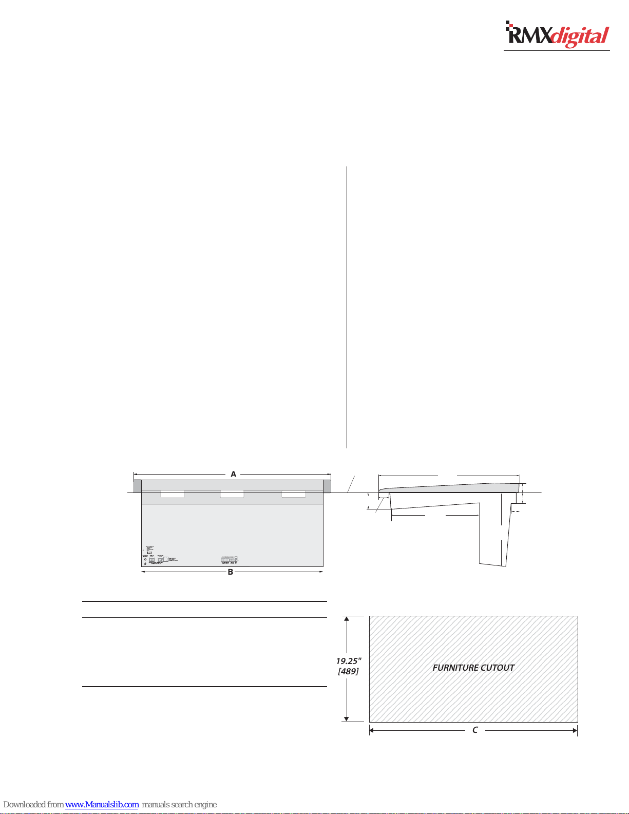
The RMX
digital
mainframe “drops into”
a cutout (as shown below) in the furniture coun-
tertop.
The console card cage, which extends below the
console, can be positioned to fall within the cabi-
net or above a cable tray.
The low-profile Reflective Display (footprint:
17.25" x 5.25") is only 5” tall. It can set behind
the frame or on top of the rear cover. If the op-
tional Tall Console Display is used, it stands on
the countertop behind the frame (its footprint: 14"
x 6", and it stands 11” tall).
Locate a 3" cable grommet near the display to
route the 6-foot cable harness thru the countertop
in order to plug into the back of the frame.
Console, back view
COUNTERTOP
2.50"
[64]
The RMX
digital
console shipment contains:
• The 12, 20 or 28 input mainframe with a Moni-
tor Control panel, a KSU card, and the DSP
cards installed with the optional items ordered
(Universal Dual Fader Panels, Blank Panels,
8-Input Expansion Cards)
• 2 RU rackmount 48-volt power supply
• Installation and tool kits (AMP MOD IV con-
nector housings and receptacle contacts, crimp
and contact removal tools, hex driver, backup
batteries, removable clear lenses and clear in-
sert sheet), two 48 VDC power cables, and CD-
ROM
• Stand alone Console Display with integral cable
and power supply
22"
2.75"
[70]
12.5"
[317.5]
[559]
9.75"
[248]
1.5"
[38]
1.5"
[38]
1.75"
[44]
Dimension Table
Mainframe A B C
RMXdigital-4 14.6" [371] 13.3" [337] 13.5" [343]
RMXdigital-12 27.4" [696] 26.1" [662] 26.25" [668]
RMXdigital-20 40.2" [1021] 38.9" [987] 39.25" [993]
RMXdigital-28 53.0" [1346] 51.7" [1312] 52.0" [1320]
Millimeter dimensions in brackets. All dimensional tolerances are: +¼"
[6.4], -0" [0.0]. Typical setback from countertop edge to the front of
the console: 6" [152] to 12" [305].
Console, side view, with dimensions
2345678901234567890123456789012123456
2345678901234567890123456789012123456
2345678901234567890123456789012123456
2345678901234567890123456789012123456
2345678901234567890123456789012123456
2345678901234567890123456789012123456
2345678901234567890123456789012123456
2345678901234567890123456789012123456
19.25"
[489]
HARRIS CORPORATION
2-1
Revision C • 10/07
2345678901234567890123456789012123456
2345678901234567890123456789012123456
2345678901234567890123456789012123456
2345678901234567890123456789012123456
2345678901234567890123456789012123456
2345678901234567890123456789012123456
2345678901234567890123456789012123456
2345678901234567890123456789012123456
2345678901234567890123456789012123456
2345678901234567890123456789012123456
2345678901234567890123456789012123456
FURNITURE CUTOUT
C
Page 18
2 Installation
Console Installation
To simplify console installation, logic cable wir-
ing diagrams for specific peripheral equipment are
available from Harris Technical Support. Refer to
page 5-1 for contact information.
INSTALLATION NOTE: Do not position the con-
sole near intense electromagnetic hum fields such
as those created by audio amplifiers that use in-
expensive power transformers operating in or near
saturation. Strong electromagnetic fields may im-
pair the performance of the RMX
boring equipment. Route audio cables to achieve
maximum practical distance from all AC power
mains wiring.
99-2667 DSP Card *
99-2665 8-Input Expansion Card (optional) 99-2672-1 or 99-2672-2 KSU Card **
80-1846 Blank Panel
The DSP, KSU and 8-Input Exp. cards are hidden below a card access cover.
* The number of DSP Cards installed is determined by the frame size.
** The 99-2672-1 KSU Card comes standard in all frame sizes.
digital
RMX
and neigh-
digital-12,
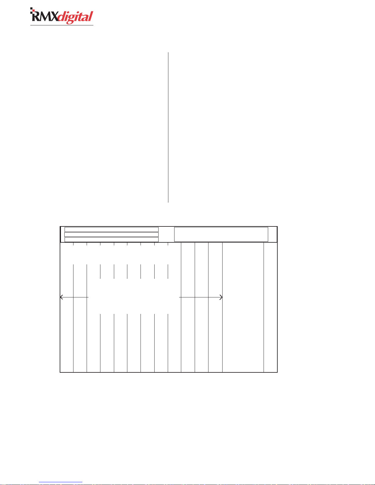
FRAME CONFIGURATION
Two panels are available for the RMX
the Universal Dual Fader Input and the Monitor
Control, which is standard on the mainframe. The
Dual Fader panel is two input slots wide, while
the Monitor Control panel is three slots wide. Typi-
cal panel positions are shown below, but panels
can be positioned up to two slots from their stan-
dard slot designations since each panel connects
to the mainframe using a single red CAT-5 cable.
Input slots can have any combination of Dual
Fader panels, single or dual width blank panels,
single or dual width divider kits, or custom switch/
control panels installed.
Contact a Harris sales representative for more
details on available RMX
Frame Configuration
digital
options.
digital
:
99-1407 Universal Dual Fader panels
take up two input slots, so there can be
up to six in a 12-input slot mainframe.
Remaining input slots are covered with
99-1410 Dual Width Blank Panels.
Input Slot 1
Input Slot 2
Input Slot 3
Input Slot 4
Input Slot 5
Input Slot 6
Input Slot 7
NONO
TE:TE:
NO
TE:
The number of available input slots equals the console
NONO
TE:TE:
model number (e.g., RMXd-20 has 20 input slots). All RMXdigital
frames have one KSU card with DSP for the buses, four input
channels and four special purpose phantom channels. Each DSP
card adds the DSP for another eight input channels (e.g., RMXd4 has no DSP card, RMXd-12 has one DSP card, RMXd-20 has
two DSP cards, and RMXd-28 has three DSP cards).
The RMXd Divider Kit allows standard Harris/PR&E Turret
Accessory Panels to be installed in a frame. There are two kits
HARRIS CORPORATION
Input Slots:
with Session, Control Room
and Studio Monitor Controls
99-1406 Monitor Control Panel (one standard)
Input Slot 8
Input Slot 9
Input Slot 10
Input Slot 11
Input Slot 12
available: 99-1411-1 is one input slot wide and holds one or
two single width turret panels; 99-1411-2 is two input slots wide
and holds two dual width panels, four single width panels, or a
combination thereof. A kit can be installed into any input slot
location. Dual Fader panels or the Monitor Control panel can be
moved left or right one or two slots to accommodate a divider kit.
Blank turret panels 99-1714-3 (1.6" x 6") or 99-1740-3 (3.2"
x 6") cover unused accessory panel openings when using the
divider kit.
2-2
99-1409 Single Width Blank Panel (standard)
Revision C • 10/07
Page 19
2 Installation
CHANNEL CONFIGURATION
Each Dual Fader panel’s specific operations and
functions are established through the settings in
the init.mac file and the current session file.
In general, Dual Fader channels are divided into
two types: VistaMax control channels and Telco
channels—which can also function as VistaMax
router control channels, but which have a special
IFB or mix-minus output assigned to each Telco
channel. Each channel in a frame comes standard
as a VistaMax control channel, but only up to six
channels can be uniquely identified as Telco chan-
nels. The Telco channels are readily apparent by
their lighted Talkback buttons.
Each channel’s functions are also configured by
the selected source signal. When a mic input is
the source, the channel strip becomes a mic chan-
nel (which means it may be controlled by a mic
remote panel, it may mute outputs and trigger a
warning lamp output when On). When a periph-
eral device is the source, the channel becomes a
line input channel (which means it may control,
and be controlled by, the peripheral device).
The six mix-minus outputs in a console can be
assigned to any six channels in the frame through
rotary switch settings on each Dual Fader panel.
NOTE: Either or both channel strips on a Dual
Fader panel can be set as a Telco input channel,
but only six total channels can be set as the six
unique Telco channels on the console.
The remaining channels in the mainframe must
have their rotary switches set to either 0 or 7. The
0 setting (the default setting for each channel) iden-
tifies it as a VistaMax control channel. The 7 set-
ting identifies that channel as being available to
be a source for control room talkback audio.
The talkback function only becomes active when
a control room mic is set as the channel’s source
and that channel’s rotary switch is set to 7.
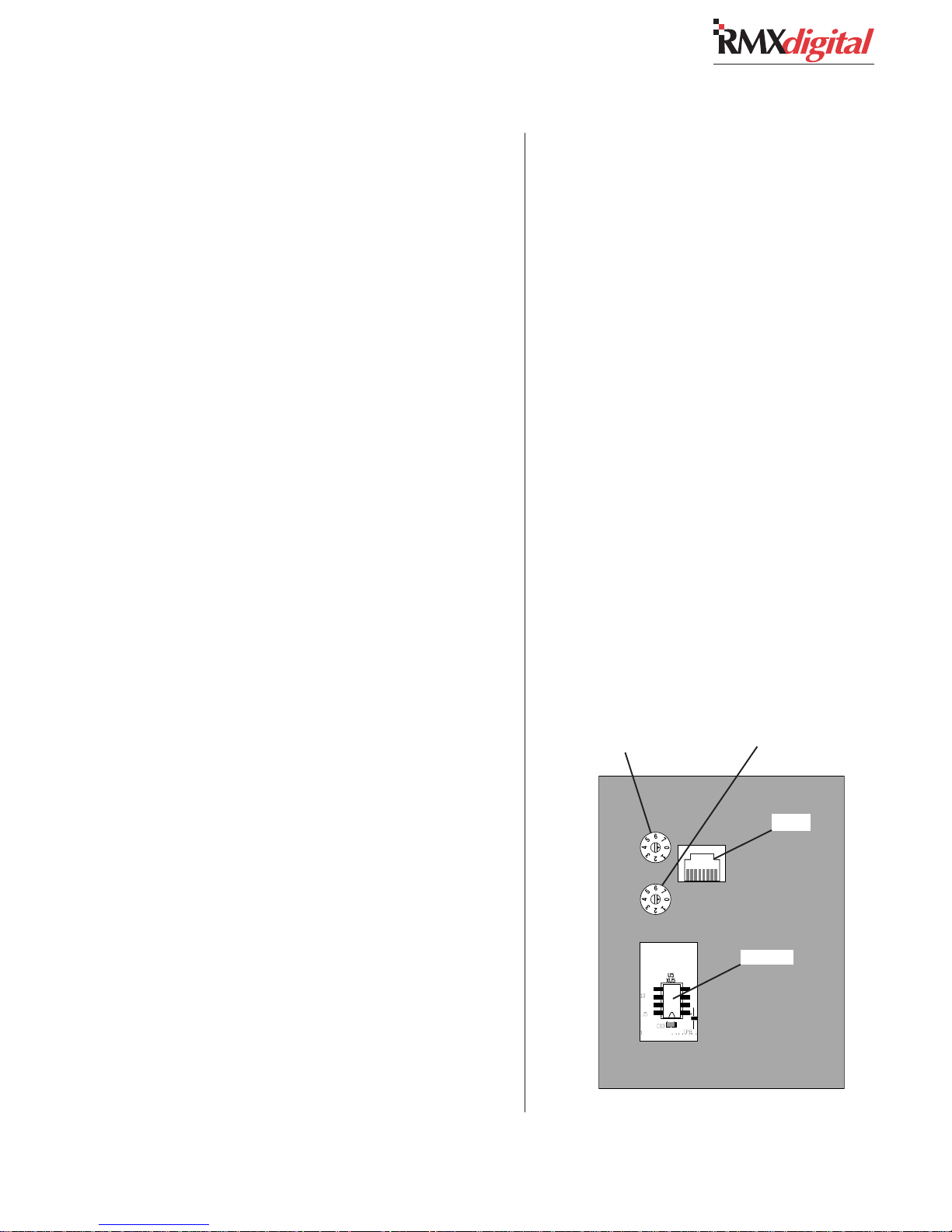
Setting Dual Fader Panel Rotary Switches
Determine which channels will be designated
as Telco channels (up to six can be assigned) and
which channel(s) should be assigned as the con-
trol room talkback source(s).
Typically, the Telco channels are grouped to-
gether but they do not have to be. For ease of con-
figuration and system troubleshooting, however,
it is best to number the Telco channels in order
from left to right in the frame (e.g. set Telco 1 as
the left-most Telco channel, then set Telco 2 as the
next one to the right, and so on).
Determine which channels will typically have
the control room mics routed to them that may
need to talk to the Telco mix-minus outputs, to
the studio and to an external location. This is typi-
cally the board operator’s mic and a producer mic,
but any number of mics could be assigned. If the
CR mics are dedicated to certain channels, than
only those channels would need to be set to 7. If
complete flexibility is required, every channel—
except for the Telco channels, could be set to 7.
Telco Channel
Number and Talk
Channel Select
Switch for the left
channel strip
Telco Channel
Number and Talk
Channel Select
Switch for the right
channel strip
RJ-45
PROM
Dual Fader Panel, bottom view
2-3
HARRIS CORPORATION
Revision C • 10/07
Page 20
2 Installation
Remove the Dual Fader panels that need to have
their rotary switches changed (from the default 0
settings) from the mainframe (see page 5-3 for
panel removal instructions). The console power can
be left on while unplugging and reconnecting the
Dual Fader panels.
Unplug the red CAT-5 cable from the panel and
turn the panel over. Several openings—for the RJ-
45 jack, two rotary switches and the PROM, are
on the back cover (shown on the previous page).
The two rotary switches are labeled 0 - 7 with
an arrow indicating the currently selected num-
ber. The upper switch sets the Telco number or
CR mic setting for the left channel strip. The lower
switch sets the Telco number or CR mic setting for
the right channel strip. If a channel strip is not a
Telco channel or a possible CR talk source, set the
switch to 0.
Change the rotary switch to position 1 to set
that channel strip as Telco 1; to position 2 to set
that channel strip as Telco 2; and so on up to po-
sition 6 which sets that channel strip as Telco 6.
Change the rotary switch to position 7 for those
channels that will have the control room talkback
mic as a source.
Once the Dual Fader panel’s rotary switches are
set, plug the red CAT-5 cable back into the RJ-45
connector and refasten each panel to the main-
frame. Verify that all channels set as Telco chan-
nels have lighted Talkback buttons. If desired, the
Talkback button cover can be replaced by a clear
cover and a label to identify each Telco channel.
There are no other adjustments or settings re-
quired on the Dual Fader panels.
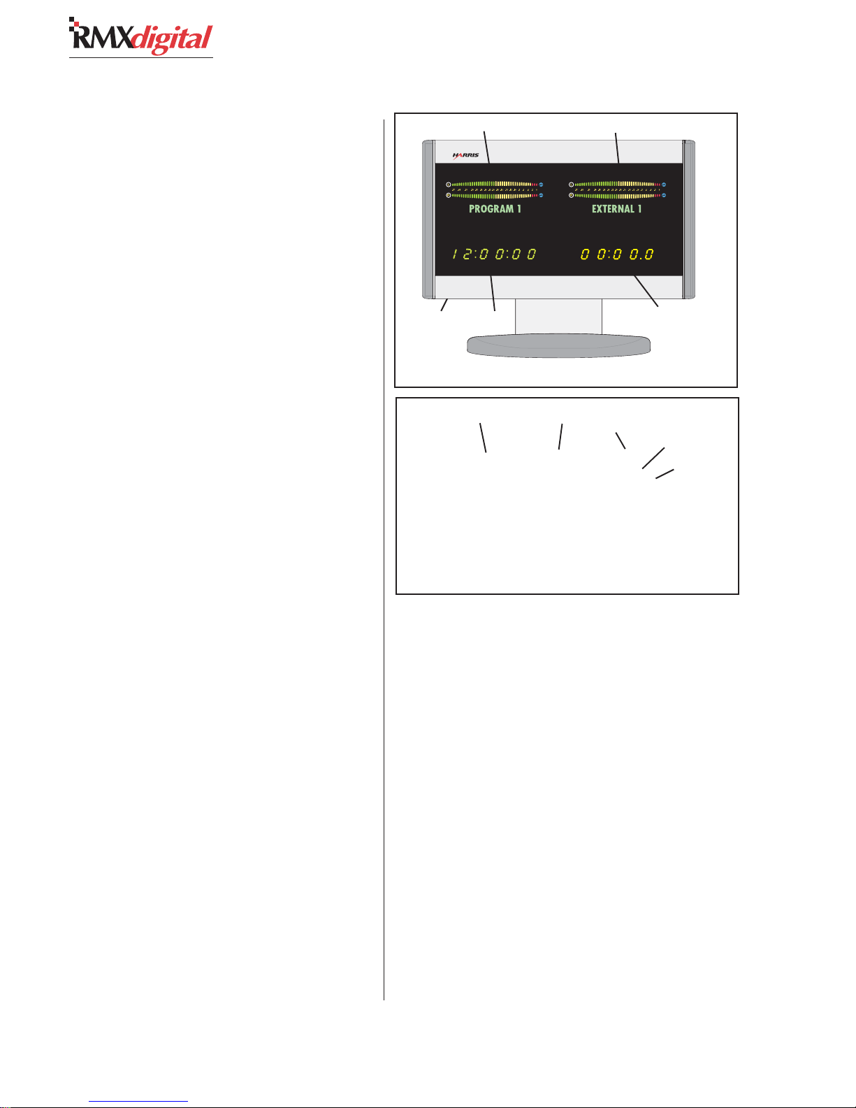
CONSOLE DISPLAY
Two console displays are available: the original
tall direct-view display (90-1950) and the low-
profile reflective display (99-1975-1). Each is po-
sitioned on the countertop behind the back of the
mainframe. The 99-1975-1 is supplied standard
Program 1 Meter Auxiliary Meter
Clock set
switches
(on bottom)
Clock
Original RMXd Console Display
Program 1 Meter Auxiliary Meter
Clock
Low-Profile Reflective Display
and the original display (90-1950) is available as
a special order. The 90-1950 is powered by a sepa-
rate 5-volt wall-wart supply (included) that plugs
into the back of the display. The low-profile dis-
play uses 48 VDC from the console. Each display
has a captive six-foot umbilical cable to carry the
meter signals, meter name display data and timer
control wires. These cables plug into keyed con-
nectors on the back of the mainframe.
Two horizontal stereo bargraph meters, with al-
phanumeric displays (PROGRAM 1, CUE, etc.)
to identify the signals, a slaveable clock, and an
event timer, are provided on each display.
The meters provide simultaneous level moni-
toring of the Program 1 bus on the left-hand meter
and another bus or system signal on the right-
hand Auxiliary Meter. The Aux Meter buttons on
the Monitor Control panel select the source for
Event
Timer
Event
Timer
Clock set
switches
(recessed)
HARRIS CORPORATION
2-4
Revision C • 10/07
Page 21
2 Installation
the right-hand meter, which switches to display
the cue bus level while Cue is active.
The meter display mode (average only or aver-
age and peak) is set by an init.mac file setting
(which is edited using the VMCC program). The
level where the blue peak indicators turn on is set
via internal DIP switches on the meter display
boards. To change these settings, the rear/bottom
cover of the Console Display must be removed.
The 12/24-hour digital clock can be slaved to
an ESE (or SMPTE in the low profile display)
master clock. An extender cable is provided in the
display umbilical cabling for the original display
so that an ESE cable can be connected at the back
of the frame. On the reflective display, an ESE or
SMPTE cable plugs into a clock board connector.
See page 6-3 for details on master clock cabling.
The event timer is controlled manually, through
buttons on the Monitor Control panel, or auto-
matically, through channel On timer reset com-
mands.
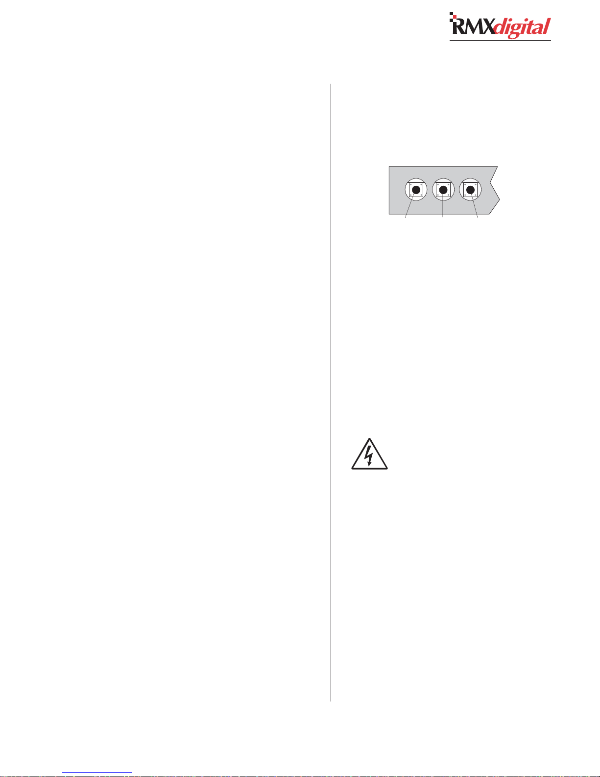
Setting The Clock
The clock can operate in autonomous or slave
mode. When used autonomously (the factory pre-
set), a quartz crystal oscillator controls clock tim-
ing. After power is applied, set the clock manually
to the current time using a nonconductive tool
(wooden swab, toothpick, etc.) to press the recessed
time-set switches (bottom left of the original dis-
play, top right on the reflective display).
• Press Fast to increment time by minutes at
a time.
• Press Slow to increment time by seconds
at a time.
• Press and hold Hold to freeze the clock to
synch it to a time reference. Set the time
slightly ahead of the reference time. Release
Hold to start the clock.
NOTE: When slave mode is selected (see Clock
Settings), if the clock is not properly connected to
an ESE or SMPTE master clock, the clock runs
off its internal oscillator. Both display colons flash
to indicate ESE timecode is not detected.
Manually Setting the Clock
(Original Display, bottom, left side)
Hold Slow Fast
(Reflective Display, top, right side)
Hold
Slow
Fas t
Setting Console Display DIP Switches
To change DIP switch settings on the meters,
timer or clock requires that the rear or bottom
cover be removed to access the various printed
circuit assemblies (PCAs) in the display.
SAFETY NOTE: Even though the
switches can be changed with power
applied, for safety, turn off the console
supply (and unplug the 5-volt wall wart
on the original display) before remov-
ing the cover. Do not touch any compo-
nents on the PCAs, other than the DIP
switches, as shown in this section.
Lay the display facedown on a padded surface
(on the reflective display remove the reflector be-
fore doing this) to remove the rear/bottom cover.
On the original display the Main Meter is the up-
per right PCA, the Aux Meter is the upper left
PCA, the clock is the lower right PCA, and the
timer is the lower left PCA. On the reflective dis-
play there are only two boards: a clock-timer board
and a meter board.
2-5
HARRIS CORPORATION
Revision C • 10/07
Page 22
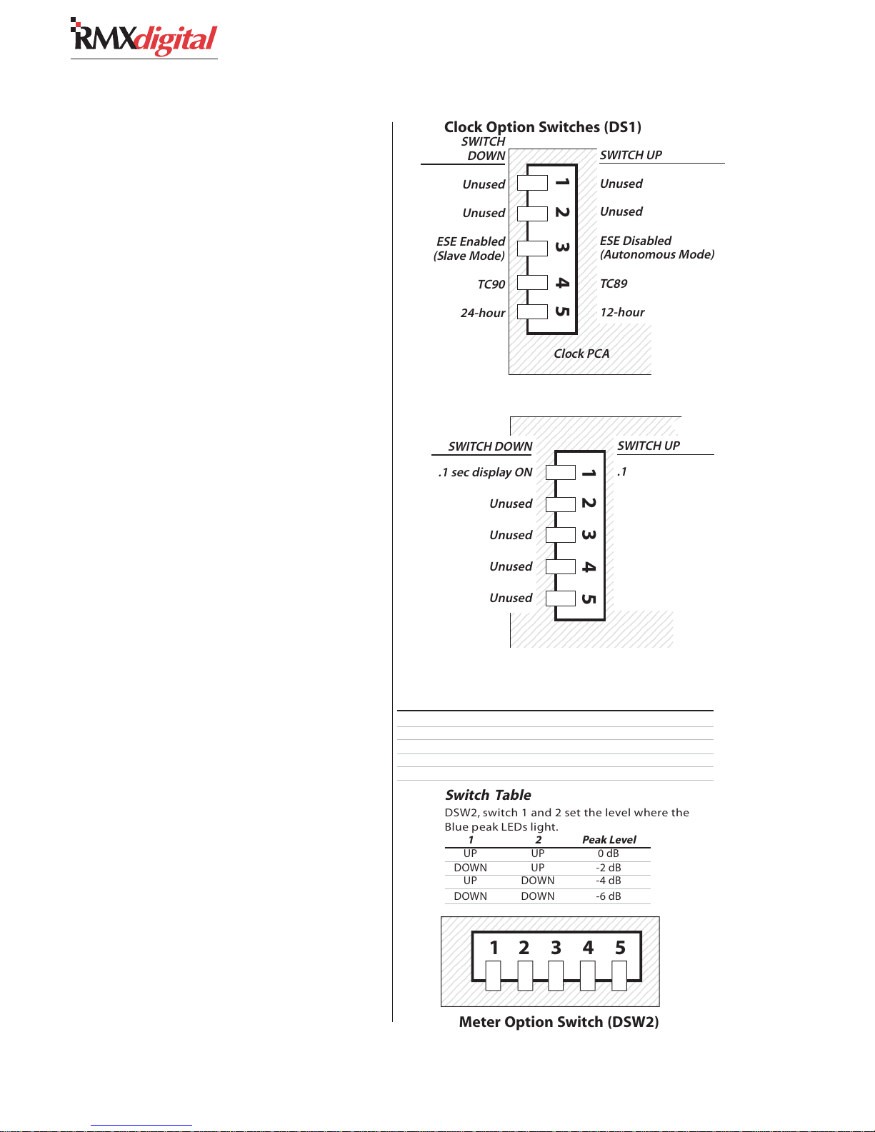
2 Installation
2
2
2
2
2
2
2
2
2
2
2
2
2
2
2
2
2
2
2
2
2
2
2
2
2
2
2
2
2
9
9
9
9
9
9
9
9
9
9
9
9
9
9
9
9
9
9
9
9
9
9
9
9
9
9
9
9
9
9
Clock Settings
The operating mode (autonomous, ESE slave
or SMPTE slave, which is only available on the
reflective display) and the clock display format (12-
or 24-hour display) are set using DIP switch DS1
on the clock PCA on the original meter and DS1
on the clock-timer PCA on the reflective meter.
For the switch settings see the illustrations for the
two displays on this and the next page.
Event Timer
The event timer displays time in minutes, sec-
onds and tenths of seconds. The only timer option
is whether the tenths of seconds digit is displayed
in Run mode. The tenths of seconds are always
shown in the Stop and Hold modes. For the switch
setting see the illustrations for the two displays
on this and the next page.
Meters
On the original display, each meter is set inde-
pendently. The Aux Meter is the left PCA, the Pro-
gram 1 Meter is the right PCA (as viewed with the
rear cover removed). On the reflective display one
set of switches set the parameters for both meters.
The switches set these parameters: the level
where the blue peak indicators turn on; whether
peak hold is active or not; and whether average
and peak or average only is displayed.
On the original display, the Program 1 Meter
has to have DSW2-5 set Down to terminate the
meter names data cable. A second DIP switch
(DSW1) assigns the meter names for each meter.
Make sure DSW1-1 is set On for the Aux Meter
and that DSW1-2 is set On for the Program 1
Meter. All other DSW1 switches must be set to
Off. For the switch settings see the illustrations for
the two displays on this and the next page.
HARRIS CORPORATION
# Switch Name DOWN Function UP Function
1 Peak Level See Switch Table See Switch Table
2 Peak Level See Switch Table See Switch Table
3 Display Mode Peak hold active No Peak hold
4unused
5 Termination Set (Main Meter) None (Aux Meter)
2-6
Revision C • 10/07
Clock Option Switches (DS1)
SWITCH
DOWN
Unused
Unused
ESE Enabled
(Slave Mode)
24-hour
23456789012345678901
23456789012345678901
23456789012345678901
23456789012345678901
23456789012345678901
23456789012345678901
23456789012345678901
23456789012345678901
23456789012345678901
23456789012345678901
23456789012345678901
23456789012345678901
23456789012345678901
23456789012345678901
23456789012345678901
23456789012345678901
23456789012345678901
23456789012345678901
23456789012345678901
TC90
23456789012345678901
23456789012345678901
23456789012345678901
23456789012345678901
23456789012345678901
23456789012345678901
23456789012345678901
23456789012345678901
23456789012345678901
23456789012345678901
12 3 45
Clock PCA
SWITCH UP
Unused
Unused
ESE Disabled
(Autonomous Mode)
TC89
12-hour
Event Timer Option Switches (DS1)
234567890123456789012345678
234567890123456789012345678
234567890123456789012345678
SWITCH DOWN
.1 sec display ON
234567890123456789012345678
234567890123456789012345678
234567890123456789012345678
234567890123456789012345678
234567890123456789012345678
234567890123456789012345678
234567890123456789012345678
234567890123456789012345678
234567890123456789012345678
Unused
234567890123456789012345678
234567890123456789012345678
234567890123456789012345678
234567890123456789012345678
Unused
234567890123456789012345678
234567890123456789012345678
234567890123456789012345678
234567890123456789012345678
Unused
234567890123456789012345678
234567890123456789012345678
234567890123456789012345678
234567890123456789012345678
Unused
234567890123456789012345678
234567890123456789012345678
234567890123456789012345678
234567890123456789012345678
234567890123456789012345678
234567890123456789012345678
SWITCH UP
12345
.1 sec display
OFF
Unused
Unused
Unused
Meter Switch DSW2 Definitions
Switch Table
DSW2, switch 1 and 2 set the level where the
Blue peak LEDs light.
12Peak Level
UP UP 0 dB
DOWN UP -2 dB
UP DOWN -4 dB
DOWN DOWN -6 dB
12 3 4 5
Meter Option Switch (DSW2)
Page 23
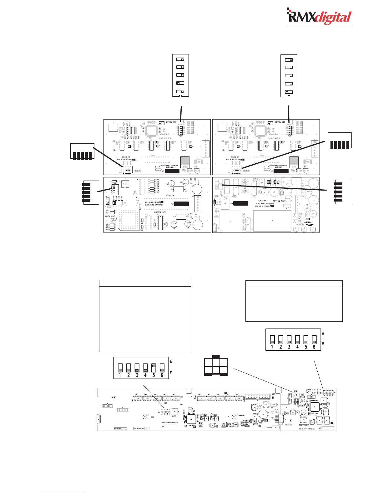
2 Installation
DSW2
DOWN
DOWN
UP
UP
UP
UP
DOWN
DOWN
Aux Meter PCA
UP
UP
DS1
ORIGINAL DISPLAY SETUP CONTROLS, REAR COVER REMOVED
Meter Boards
Switch DS3 Settings
Switch - Off Function / On Function
1 - Average & Peak / Average only
2 - 2 sec. Peak Hold / No Peak Hold
3 - Blue LED turn on level*
4 - Blue LED turn on level*
5 - NetWave / RMXdigital
6 - Display: mirrored /direct view
* Blue Peak LEDs turn on at:
-6 dBFS when both 3 and 4 are off
-4 dBFS when 3 is on and 4 is off
-2 dBFS when 3 is off and 4 is on
0 dBFS when both 3 and 4 are on
(Default Settings)
DSW1
ON
OFF
1 2 3 4 5
Main Meter PCA
Clock PCATimer PCA
J4 SIGNALS
1 - TIMER RESET INPUT
2 - GROUND
3 - TIMER RESET OUTPUT
4 - GROUND
5 - ESE/SMPTE INPUT +
6 - ESE/SMPTE INPUT -
6 5 4
3 2 1
Wire insertion end view
1 2 3 4 5
DSW1
DSW2
DOWN
UP
UP
UP
UP
DOWN
Clock & Event Timer Board
Switch DS1 Settings
Switch - Off Function / On Function
1 - Timer .1 secs display / Timer .1 secs off
2 - ESE not used / ESE master clock
3 - unused
4 - 12-hour time / 24-hour time
5 - SMPTE not used / SMPTE master clock
6 - Display: mirrored / direct view
ON
OFF
(Default Settings)
DOWN
DOWNUPDOWN
DS1
Meter PCA Clock-Timer PCA
REFLECTIVE DISPLAY SETUP CONTROLS, BOTTOM COVER REMOVED
2-7
HARRIS CORPORATION
Revision C • 10/07
Page 24
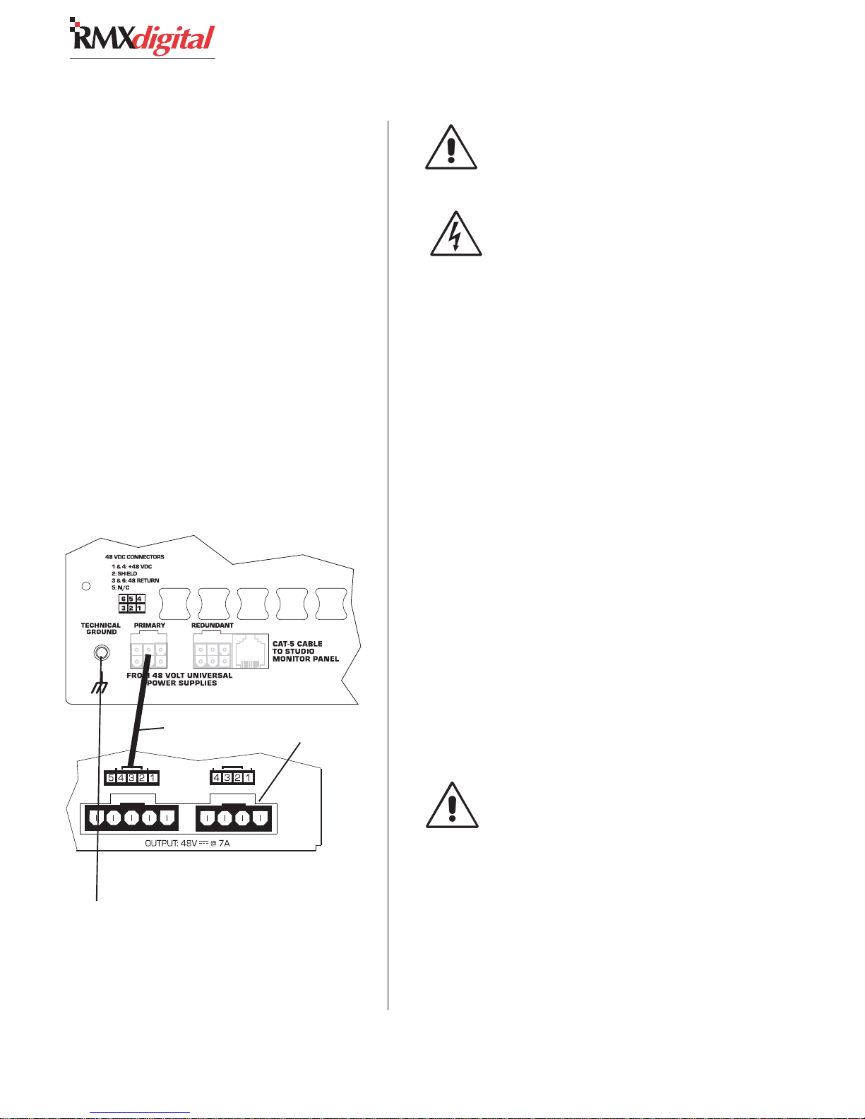
2 Installation
POWER SUPPLY
The 48-volt Power Supply (99-1205) requires
2 RU of rack space within the console cabinetry,
typically below and to the left or right of the con-
sole. The supply must be installed such that the
keyed fifteen foot DC supply cable (90-1858-1) is
not under any tension when routed through the
cabinet. It locks into the Primary power connec-
tor on the frame’s rear panel (see drawing below).
A second 99-1205 supply can be installed as a
redundant supply since the console has an inte-
gral power coupler. It plugs into the Redundant
power connector using a second power cable, sup-
plied with the console mainframe.
99-1205 P99-1205 P
99-1205 P
99-1205 P99-1205 P
TT
echnicechnic
T
echnic
TT
echnicechnic
RMXdigital mainframe detail, rear, left lower
oo
ww
er Ser S
o
w
er S
oo
ww
er Ser S
al Gal G
rr
ound Cound C
al G
r
ound C
al Gal G
rr
ound Cound C
90-1858-1 Cable
upply andupply and
upply and
upply andupply and
onneconnec
onnec
onneconnec
tionstions
tions
tionstions
no connection
DC GROUNDING NOTE:
connect
ing to the chassis of the power supply.
the audio or logic ground wir-
Do not
AC GROUNDING NOTE: Do not
defeat the power cord “U” safety
ground in any way. Doing so may cre-
ate a potentially dangerous condition
to the operator.
GROUNDING AND SHIELDING
Connect the broadcast facility’s technical ground
to the
RMXdigital
insert provided on the rear of the chassis near the
power connectors. Use a 10-32 machine screw and
crimp lug to terminate the facility’s technical
ground wire.
Connect audio cable shields at both the console
and the peripheral ends when all system compo-
nents share a common ground potential and are
using isolated ground AC outlets tied individually
back to the main technical ground.
If isolated ground AC outlets are not available,
connect the cable shield at the console end only.
Shields should be floated (left unconnected) at the
peripheral device end. Ensure the peripheral de-
vices connect to a clean ground through their
power cords, or through separate ground wires to
the facility’s technical ground.
mainframe, using the threaded
48-Volt Power Supply, rear panel detail
Threaded insert
for technical
ground wire
connection
Two 90-1858-1 cables ship
with the RMXdigital mainframe. Use one cable for the
primary 48-volt supply, use
the second one for a
redundant 48-volt supply
HARRIS CORPORATION
.
2-8
Revision C • 10/07
GROUNDING NOTE: The Power Sup-
ply chassis connects to the AC mains
safety or “U” ground wire.
AUDIO GROUND NOISES: Buzz
pickup is generally electrostatic—such
as capacitive coupling between an au-
dio line and an AC power line. To avoid
audio ground noises, do not route au-
dio wires in the same wireway as an
AC power line.
Page 25
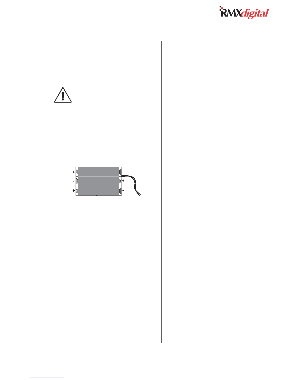
BACKUP BATTERIES
Three AA rechargeable NiCad batteries (part of
the Tool Kit) supply a “Keep Alive” voltage to main-
tain the console assignments during momentary
power outages.
Do NOT install the batteries until the
console is powered 24/7 and is ready
for everyday use.
To install the backup batteries:
1 Open the card access cover.
2 Install the three batteries into the battery clip
located behind the KSU card on the frame.
Observe the polarity as marked on the bat-
tery clip, and shown below.
2 Installation
Backup Battery Polarity
NOTE: Check/replace the batteries yearly to
prevent leakage damage and ensure continuous
backup protection. Use only Panasonic P-50AAH
or equivalent batteries designed for continuous
slow charging. To prolong battery life and prevent
leakage damage, remove the batteries when leav-
ing the console off for any extended period.
2-9
HARRIS CORPORATION
Revision C.1 • 12/10
Page 26

2 Installation
Cabling and Wiring
Before installing the RMX
ate a facility wiring plan to list the console inter-
connections with all peripheral devices. Identify
and create tags for the audio and logic cabling.
List each connection in a master facility wiring
logbook to facilitate the wiring installation, any
future system wiring changes, equipment updates,
and system troubleshooting.
Refer to the Quick Connection Guides, on pages
2-18 to 2-24, for information on audio and logic
connection. See page 2-13 for a block diagram for
each type of logic interface.
CONNECTOR ACCESS
All audio, logic and data connections are made
on plug-in connectors. They are hidden in normal
operation below a card access cover that extends
across the console behind the user control panels.
To access the connectors, open up the card ac-
cess cover by lifting from the front using the thumb
catches on either end of the cover. It is hinged to
open toward the rear and stay open.
Caution: Make sure the cover is fully open so
that it does not accidentally fall shut.
REQUIRED CABLES AND WIRE
The following types are required:
• Analog audio connections require two-
conductor, stranded, insulated, shielded
cable using a separate shield drain wire
(equivalent to Belden 8451, 9451 or 8761).
• AES/EBU connections use 110 ohm two-
conductor, stranded, insulated, foil-shield
cable containing a separate shield drain
wire (equivalent to Belden 1800A).
• Logic control cables require stranded, 22
AWG, multiple-conductor, non-shielded,
jacketed cable (equivalent to Belden 9423,
8457 or 9421). The number of conductors
digital
console, cre-
needed is determined by the application.
Typically, cables with five or eight wires are
most often used for constructing logic cables
since even though there are twelve or four-
teen pins on the logic connectors, only a
handful are typically connected for any
given application.
• Crossover CAT-5e/6 cable to connect the
KSU Facet connectors to a VistaMax frame.
• Straight-thru CAT-5 cable to connect the
KSU Ethernet connector to a VistaMax sys-
tem LAN switch.
WIRE PREPARATION
All RMXd audio and logic wiring terminates in
AMP MOD IV receptacle contacts at the console.
Stranded wires, of 22 to 26 AWG with insulation
diameters of .040 to .060 inch, can be used with
the AMP MOD IV receptacle contacts.
Follow these steps for audio wire preparation:
1 Strip the cable insulation jacket and foil shield
back 1½" [38.10 mm].
2 Remove the foil shield and sleeve the drain
wire with 20 AWG Teflon sleeving. Leave
9/64" [3.57 mm] of the drain wire exposed.
3 Cover the cut end of the jacket with 3/4"
[19.05 mm] of heat-shrink tubing. Shrink this
tubing, centered on the jacket cut end, to hold
the drain wire sleeving in place.
4 Strip the signal wire insulation back 9/64"
[3.57 mm].
5 Crimp the receptacle contact onto the wire
and insulation.
AA
udio Cudio C
able Sable S
A
udio C
AA
udio Cudio C
mended grounding procedures, the drain wires
must be sleeved with Teflon sleeving and heat
shrink tubing must cover all cable jacket cut ends
to insulate the shield wiring.
Logic control cables are fabricated in a similar
manner to the audio wiring. Strip the jacket insu-
lation back 1½" [38.10 mm], sleeve the cut end
able S
able Sable S
hielding Nhielding N
hielding N
hielding Nhielding N
otot
e:e:
ot
e: To follow recom-
otot
e:e:
HARRIS CORPORATION
2-10
Revision C • 10/07
Page 27
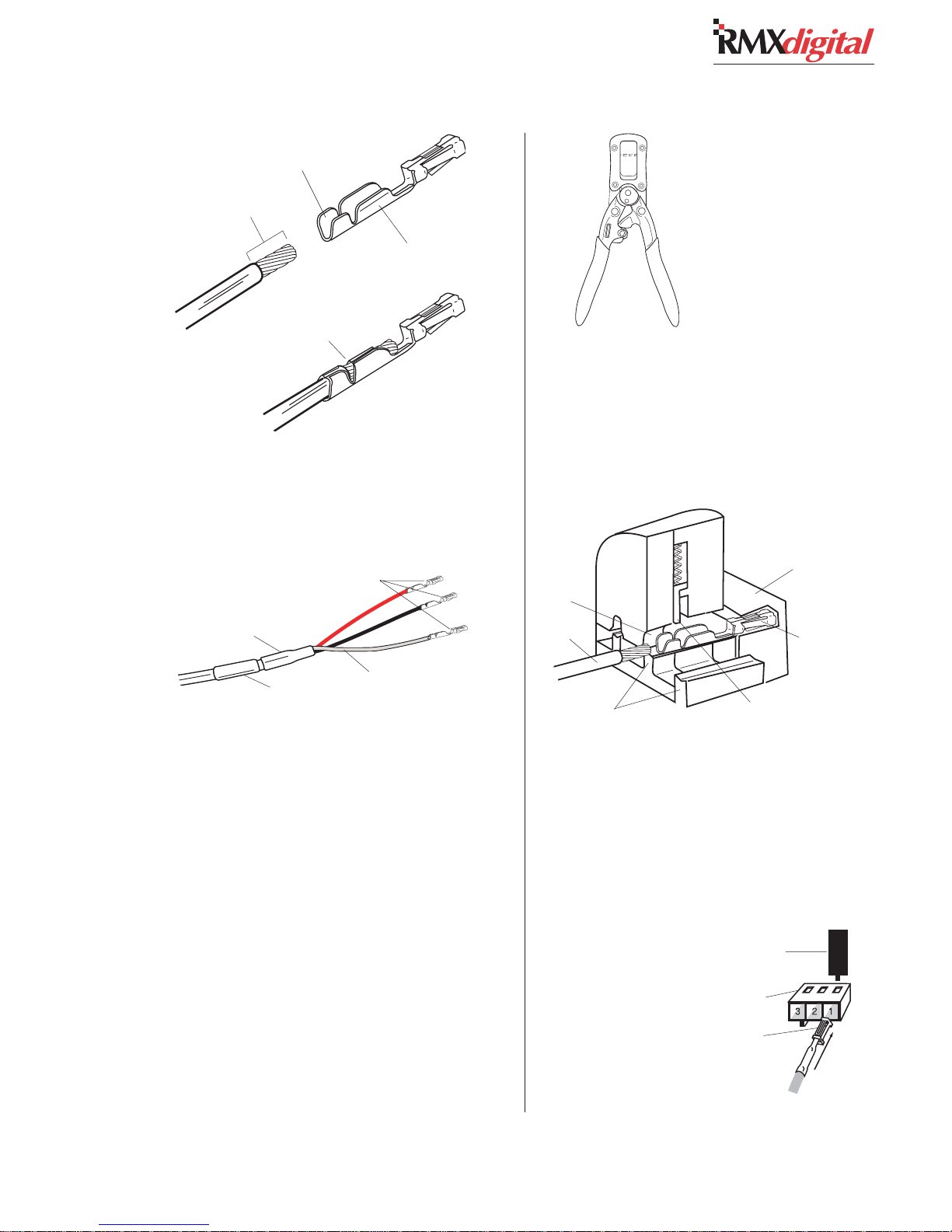
Insulation
Crimping Barrel
2 Installation
9/64” [3.57 mm]
Wire Crimping
Barrel
Properly
Crimped Contact
AMP MOD IV Receptacle Contacts
with 3/4" [19.05 mm] of shrink tubing and strip
the insulation from each wire 9/64" [3.57 mm].
AMP MOD IV
Receptacle Contacts
3/4” [19.05 mm]
Tefl on S le evi ng
Cable ID Tag
Audio Wire, ready for insertion into an
AMP MOD IV
Contact
Crimp Tool
2 Insert the prepped wire into the contact until
the insulation hits the tool’s wire stop. Hold
the wire in place while squeezing the tool
handles to crimp the contact onto the wire.
The tool handles automatically release and
spring open after the crimp cycle is complete.
Contact Holder,
snapped against
Crimp Tool
Die
Wire
Printed
Side of
Anvils
Crimp
To o l
Insulation Stop
AMP MOD IV
Receptacle
Contact
CRIMP TOOL OPERATION
A ratcheting AMP crimp tool with contact holder
is included. The tool crimps both the insulation and
wire barrels on the AMP MOD IV receptacle con-
tact in one crimp. To use the ratcheting crimp tool:
1 Insert the contact into the contact holder with
the barrel openings up. Typically the middle
holder is used (for 20 - 24 AWG wire). Flip
the holder up so it magnetically latches against
the crimp tool. The end of the insulation bar-
rel will be about 2 mm from the end of the
die. Close the tool one click (only until the
anvil holds the contact in place, as shown in
the cutaway view, above.)
Crimp Tool — Cutaway View
Once the contact has been crimped, insert and
lock the contact receptacle into the appropri-
ate connector housing following the pinout
diagrams found on pages 2-10 (for audio) and
2-13 (for logic).
Contact Removal Tool
Locking Tab Slots
Locking Tab
Receptacle Contact,
Insertion & Removal Detail
2-11
HARRIS CORPORATION
Revision C • 10/07
Page 28
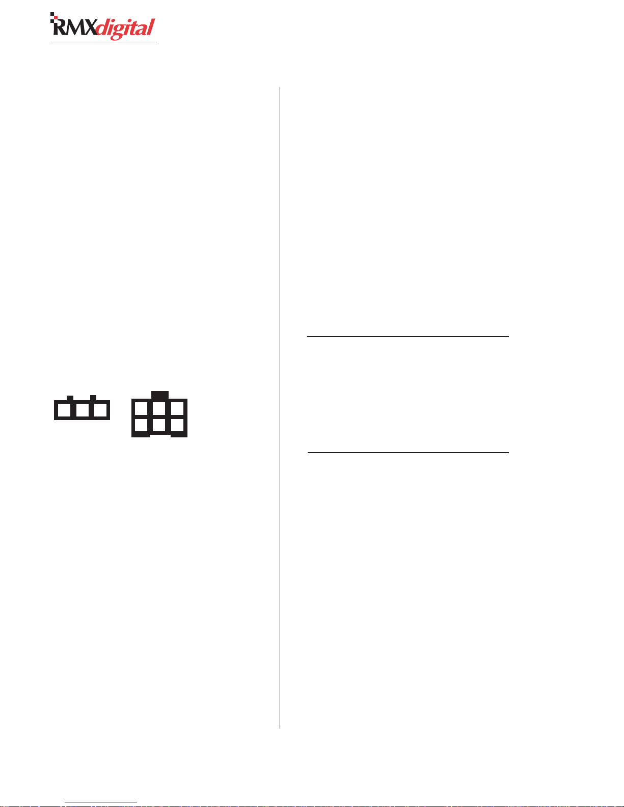
2 Installation
A receptacle contact is inserted into the hous-
ing with its locking tab side toward the locking
tab slots on the side of the connector housing. A
slight click can be heard when the contact’s lock-
ing tab springs up into the locking tab slot.
To remove a contact from a housing, the 70-
129 Contact Removal Tool (included in the 76-
1401 tool kit) is required. Insert the tool’s tip into
the locking tab slot and press the locking tab down
while lightly pulling on the wire to remove the
contact from the housing.
AUDIO CONNECTIONS
Analog and digital audio connections take ad-
vantage of the three-pins per row design of the
AMP MOD IV housings. Three-pin housings are
used for digital connections and six-pin housings
are used for analog connections.
Digital & Analog Audio Connectors
1 2 3
3-pin Digital
connector
Pin numbering, wire insertion end view,
KSU connector orientation
Audio wiring has this orientation:
• The audio shields connect on pins 1 and 4
• The audio low wires, typically black,
connect to the middle pins (pins 2 and 5)
• The audio high wires, typically red,
connect to pins 3 and 6
When inputs come from mono sources like mic
processors or hybrids, two separate signals can
connect to each six-pin connector to maximize
input connector usage.
Analog Connections
There are no analog interstage patch points in
the RMX
patch bay, connect line level analog outputs from
the peripheral devices directly to the patch bay.
digital
6 5 4
321
6-pin Analog
connector
console. To use the console with a
Normal these signals to the appropriate analog
inputs.
Likewise, the RMX
digital
’s analog outputs may
be routed through a patch bay normalled to stan-
dard peripherals such as analog on-air processing
gear, recorders, telephone hybrids, etc.
Each analog input is designed for line level (+4
dBu). Session file settings allow any input to be
software level trimmed (by up to +/-15 dB) so that
unbalanced -10 dBv devices can be directly con-
nected to the console. Note that microphones must
be separately preamplified and processed before
being connected to the console.
Stereo Analog Audio Connections
Line Input or Output — 6-Pin Housing
Pin Signal Description
1 Shield for the left channel
2 Low (-), left channel
3 High (+), left channel
4 Shield for the right channel
5 Low (-), right channel
6 High (+), right channel
Two Mono Analog Connections
Line Input or Output — 6-Pin Connector
Pin Signal Description
1 Shield for signal 1
2 Low (-) for signal 1
3 High (+) for signal 1
4 Shield for signal 2
5 Low (- ) for signal 2
6 High (+) for signal 2
Digital Connections
Three-pin digital inputs accept AES-3 (AES/
EBU) compatible signals with sample rates of 25
to 50 kHz. Each digital input goes through sample
rate conversion (the console’s internal sample rate
is 48 kHz). In most cases, digital inputs can also
accept unbalanced S/PDIF signals. Refer to Un-
balanced Connections on the next page for details.
Each digital output is an AES-3 compatible sig-
nal. AES-3 outputs cannot connect directly to an
S/PDIF input. To do this requires a signal trans-
lation interface.
HARRIS CORPORATION
2-12
Revision C • 10/07
Page 29
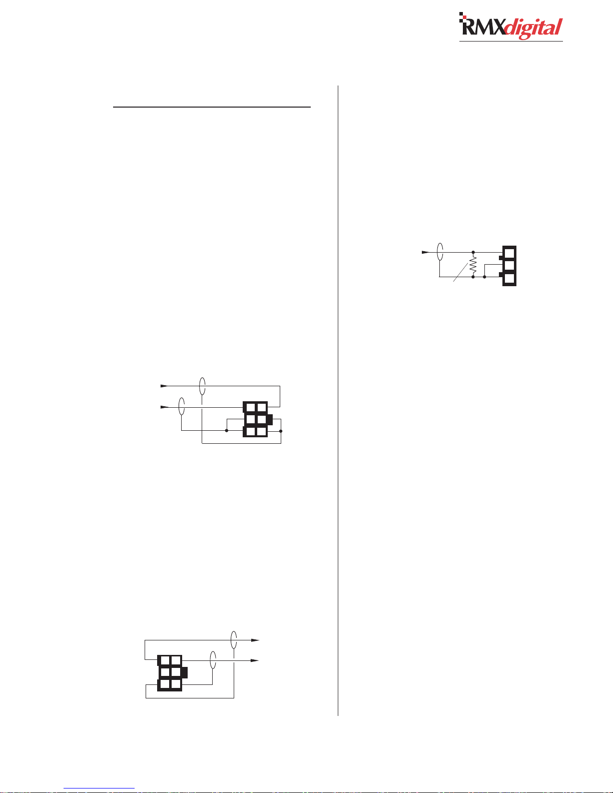
2 Installation
AES/EBU Digital Inputs & Outputs
Pin Signal Description
1 Shield (connects directly to the chassis)
2 Low (-)
3 High (+)
UNBALANCED CONNECTIONS
Although all analog inputs and outputs are
active and balanced, unbalanced consumer or
“semipro” equipment can be connected to the con-
sole. For best results, connect an unbalanced de-
vice through an IHF-PRO match box and keep
the unbalanced cable lengths as short as possible.
If a match box is not available, connect an un-
balanced device directly to a RMX
using the following illustration.
Connecting an Unbalanced Stereo Device
to an RMX
From the
Unbalanced
Device
R
L
Shields
digital
Analog Input
When an unbalanced device must be connected
to an RMX
digital
balanced analog output, and
an IHF-PRO match box is not available, do not
tie the low (-) and shield pins together to “unbal-
ance” the signal. The low output pin must always
be left floating when unbalancing an RMX
output, as shown in the following illustration.
Connecting an Unbalanced Device
to an RMX
Balanced
(Make no connections to pins 2 & 5)
digital
Analog Output
(Nominal Output is -2 dBu)
Console
Output
36
25
14
digital
Console
Balanced
Input
36
25
14
To the
Unbalanced
Device
L
R
Shields
input
digital
S/PDIF Signals
Digital devices with only an S/PDIF digital out-
put can connect to an RMX
digital
input, but only
if a 249 ohm resistor is used to impedance match
the S/PDIF cable. Install the resistor in the AMP
MOD IV housing per the following illustration.
Connecting an S/PDIF Device to
an RMX
S/PDIF
Device
Signal
Shield
digital
From
249 ohm resistor
AES/EBU Input
Console
AES/EBU
Input
3
2
1
An unbalanced-to-balanced line transformer can
alternately be used to interface an S/PDIF signal.
Note 1: A signal conversion interface must be
used to connect an AES/EBU output to a S/PDIF
input.
Note 2: Some S/PDIF signals may not work with
the RMX
digital
’s inputs, even with the additional
load resistor or a transformer, because of nonstand-
ard levels or protocols in the S/PDIF product.
RMXDIGITAL SAMPLE RATE
The RMX
sample rate of 48 kHz for all its internal audio
mixing and routing. Each digital input has an in-
tegral sample rate converter to convert sample
rates from 25 to 50 kHz to the console’s internal
48 kHz sample rate.
The console’s digital outputs are fixed at 48 kHz,
except for PGM 1, PGM 2, Send, and KSU Out-
puts A and B. Each can be set for 44.1 kHz in the
init.mac file (see Chapter 4 for how to change
the sample rates on these outputs).
When the console is used in a stand-alone ap-
plication, the console cannot be locked to an ex-
ternal time reference. To accomplish this, the RMX-
digital
digital
uses the professional audio
must be networked in a VistaMax system
2-13
HARRIS CORPORATION
Revision C • 10/07
Page 30

2 Installation
(the RMX
digital
is then automatically synchro-
nized to the VistaMax system’s master clock).
An external AES-3 digital reference signal
(48 kHz, ±100 ppm) can connect to the master
Hub card in a VistaMax frame. Refer to the Vis-
taMax manual (75-52) for details.
AUDIO CONNECTIONS
There are eighteen dedicated analog and digi-
tal outputs on the KSU card (see pg 2-19) for the
bus outputs (PGM 1-PGM 4 and Send), monitor
outputs for the control room and a studio, three
Talkback audio-only outputs, a mono cue output,
and four analog and four digital routable outputs.
There are also four analog and four digital in-
puts on the KSU. The signals on these connectors
are routed to channel strips by session file com-
mands or by “dialing” them up using the Dual
Fader panel source selectors. During console con-
figuration, the inputs can also be made available
to any VistaMax device in the network.
The eight routable outputs can have dedicated
signals routed to them in the init.mac file; by
assigning a signal in a session file; or they can be
assigned as a destination controlled by a VistaMax
source selector.
Each routable connector defaults to stereo link-
ing, but any analog input or output connector can
be set to function as a two mono outputs. See Chap-
ter 4 for more information on stereo versus mono
signals.
Additional audio inputs are available on all
frame sizes, except the RMX
or more optional 8-Input Expansion Cards. One
8-Input Expansion card can be added to each DSP
Card. The cards have eight audio inputs and eight
logic I/O connections. Card DIP switches set each
audio input as an analog or a digital input. The
eight logic connectors are associated with one of
the audio connections, as detailed in the next sec-
tion.
d
-4, by adding one
LOGIC CONNECTORS
The RMX
connections:
• Assignable Logic I/O (three on the KSU
• Control Room logic for warning light, ex-
• Studio logic for warning light, external
• Cue/Talk/External logic from a remote cue
Page 2-13 has block diagrams for the four types
of logic interfaces. All logic inputs and outputs
are opto-isolated through opto-couplers on their
inputs and solid state relays on their outputs. The
inputs handle logic from +5 to +40 volts. The out-
puts are solid-state “dry-contact relays” that can
switch up to 60 volts, AC or DC.
The CR, Studio and Cue/Talk/Ext. logic con-
nectors are dedicated to the functions that are
shown in the block diagrams. There are no soft
configurations required on these connections.
The Assignable Logic I/O connectors have de-
fault logic functions, as shown throughout this
manual, but the logic inputs have additional func-
tions that can be substituted for the default set-
tings during configuration using VMCC.
An Assignable Logic connector can be “bound”
or associated to an audio connector. On the KSU
Card, audio input A is typically connected to the
Board Operator’s mic preamp and hence does not
have a logic connector associated with it, thus the
three Assignable Logic I/O connectors are labeled:
B, C and D since they are associated with KSU
audio inputs B, C and D. Thus, if audio input B
connects to CD1, CD1’s logic would connect to
the B Logic I/O connector. Likewise, audio inputs
C and D are associated with the C and D Logic
digital
console has the following logic
and eight on each 8-Input Expansion card).
ternal mute, dim, and talkback control.
mute, dim, and talkback control.
logic input; a remote timer reset output; an
external location mute, dim and talk com-
mands; and an external talk to CR logic
input.
HARRIS CORPORATION
2-14
Revision C • 10/07
Page 31

Control Room Logic Interface,
Connector Pinout and Block Diagram
Enable Logic Inputs (+)
2 Installation
Control Room Warning Relay
4
Control Room Warning Relay
5
Control Room Dim Relay
14
12
1 2 3 4 5 6 7
8 9 10 11 12 13 14
Wire insertion end view
1 - LOGIC GND
2 - LOGIC GND
3 - LOGIC GND
4 - WARNING RELAY
5 - WARNING RELAY
6 - +5 VOLT LOGIC SUPPLY
7 - +5 VOLT LOGIC SUPPLY
8 - MUTE C/R (-)
9 - DIM C/R (-)
10 - RELAYS COMMON
11 - MUTE RELAY
12 - DIM RELAY
13 - TALK TO C/R RELAY
14 - ENABLE LOGIC INPUTS (+)
Studio Logic Interface,
Connector Pinout and Block Diagram
1 2 3 4 5 6 7
8 9 10 11 12 13 14
Wire insertion end view
1 - LOGIC GND
2 - LOGIC GND
3 - LOGIC GND
4 - WARNING RELAY
5 - WARNING RELAY
6 - +5 VOLT LOGIC SUPPLY
7 - +5 VOLT LOGIC SUPPLY
8 - MUTE STUDIO (-)
9 - DIM STUDIO (-)
10 - RELAYS COMMON
11 - MUTE RELAY
12 - DIM RELAY
13 - TALK TO STUDIO RELAY
14 - ENABLE LOGIC INPUTS (+)
Cue/Talk/External Logic Interface,
Connector Pinout and Block Diagram
Ctrl Room Mute Input (-)
Ctrl Room Dim Input (-)
Notes:
Opto-Isolated inputs are current limited to work
with +5 to +40 VDC logic.
Opto-Isolated outputs can sink up to 60 volts or
350 mA max. current flow.
For fully isolated operation, do not connect external
devices to +5 or ground (pins 1, 2, 3, 6 and 7).
Enable Logic Inputs (+)
Studio Mute Input (-)
Studio Dim Input (-)
Notes:
Opto-Isolated inputs are current limited to work
with +5 to +40 VDC logic.
Opto-Isolated outputs can sink up to 60 volts or
350 mA max. current flow.
For fully isolated operation, do not connect external
devices to +5 or ground (pins 1, 2, 3, 6 and 7).
Enable Logic Inputs (+)
8
9
14
8
9
10
Control Room M ute Relay
11
Talk to Control Room Relay
Internal Logic
Internal Logic
13
Relays Common
10
Logic Supply +5VDC
7
Logic Supply +5VDC
6
Logic Ground
1
Logic Ground
2
Logic Ground
3
Studio Warning Relay
4
Studio Warning Relay
5
Studio Dim Relay
12
Studio Mute Relay
11
Talk to Studio Relay
13
Relays Common
10
Logic Supply +5VDC
7
Logic Supply +5VDC
6
Logic Ground
1
Logic Ground
2
Logic Ground
3
External Timer Reset
4
External Dim Relay
7
1 2 3 4 5 6
7 8 9 10 11 12
Wire insertion end view
1 - +5 VOLT LOGIC SUPPLY
2 - LOGIC GND
3 - RELAYS COMMON
4 - TIMER RESET
5 - TALK TO EXT. RELAY
6 - EXTERNAL MUTE RELAY
7 - EXTERNAL DIM RELAY
8 - +5 VOLT LOGIC SUPPLY
9 - LOGIC GND
10 - ENABLE LOGIC INPUTS (+)
11 - EXT TALK TO C/R (-)
12 - REMOTE CUE (-)
Assignable Logic Interface,
Connector Pinout and
Block Diagram, default signals
1 2 3 4 5 6
7 8 9 10 11 12
Wire insertion end view
1 - LOGIC GND
2 - TALK TO C/R / CUE (-)
3 - OFF (-)
4 - ENABLE LOGIC INPUTS (+)
5 - OFF TALLY / STOP PULSE
6 - TALLY & PULSE COMMON
7 - +5 VOLT LOGIC SUPPLY
8 - COUGH / READY (-)
9 - ON (-)
10 - +5 VOLT LOGIC SUPPLY
11 - ON TALLY / START PULSE
12 - +5 VOLT LOGIC SUPPLY
Ext Cue On Input (-)
Ext Talk to CR Input (-)
Notes:
Opto-Isolated inputs are current limited to work
with +5 to +40 VDC logic.
Opto-Isolated outputs can sink up to 60 volts or
350 mA max. current flow.
For fully isolated operation, do not connect external
devices to +5 or ground (pins 1, 2, 8, and 9).
Enable Logic Inputs (+)
On (-)
Off (-)
MIC: Cough (-)
LINE: Ready (-)
MIC: Talk To C/R (-)
LINE: Cue (-)
12
11
4
9
3
8
2
Notes:
Opto-Isolated inputs are current limited to work
with +5 to +40 VDC logic.
Opto-Isolated outputs can sink up to 60 volts or
350 mA max. current flow.
For fully isolated operation, do not connect external
devices to +5 or ground (pins 1, 7, 10, and 12).
2-15
HARRIS CORPORATION
Revision C • 10/07
External Mute Relay
6
Talk to External Relay
Internal Logic
5
Relays Common
3
1
Logic Supply +5VDC
Logic Supply +5VDC
8
Logic Ground
2
Logic Ground
9
MIC: On Tally Relay
11
LINE: Start Pulse Relay
MIC: Off Tally Relay
5
LINE: Stop Pulse Relay
Tally & Pulse Common
6
7
Logic Supply +5VDC
Logic Supply +5VDC
10
Logic Supply +5VDC
12
Logic Ground
1
Internal Logic
Page 32

2 Installation
connectors. The “binding” of the audio and logic
connections is set using VMCC which is covered
in chapter 4, RMX
digital
Server and in Appendix
A, VMCC.
CONNECTION QUICK GUIDES
Pages 2-18 to 2-24 have Quick Guides covering
the connections for each card or component along
with audio and logic connector pinouts and sig-
nal descriptions. Logic block diagrams are shown
on page 2-13. Here are the Quick Guide pages:
• Frame and Console Display: page 2-18
• KSU card: pages 2-19 thru 2-22
• 8-Input Expansion card: page 2-23
• VistaMax connections: page 2-24
Pages 2-25 to 2-27 show examples of typical
logic connections to the Assignable Logic connec-
tors from a mic remote control panel, a CD player
and a digital delivery system.
Note: For complete isolation of the console and
a peripheral device, use only the opto-isolated con-
trol connections. Both logic ground and +5 VDC
are referenced to the console’s power supply and
ground and should only be connected to isolated
devices like mic control panels or other Harris
Accessory Panels. Connecting logic ground to a
non-isolated device may result in a ground loop
between the console and the peripheral device.
LOGIC INTERFACE
Logic connector pinouts and block diagrams for
the four types of logic connections on the RMX-
digital
(Control Room, Studio, Cue/Talk, Assign-
able) are shown on page 2-13.
Logic inputs are shown on the left side and logic
outputs are shown on the right side of the block
diagrams. Logic inputs, noted by the (-) symbol,
are active low. They are isolated by opto-couplers
that must be tied to +5 to +40 volts through the
Enable Logic Inputs pin.
Most outputs are isolated solid-state relay con-
tacts commoned to one pin. The exceptions are
the two warning relay outputs which are isolated
dry contacts. The common pin can tie to ground
(for low logic outputs) or to a logic voltage of up
to 60 volts at 350 mA (for high logic outputs).
Several +5 volt supply and ground pins are avail-
able on each connector, but these should only be
used to power isolated control panels. Ground and
logic voltages should always be sourced from the
peripheral device to maintain isolated operation.
Control Room Logic
This 14-pin connector has two isolated relay
contacts (pins 4 and 5) for controlling a warning
lamp interface like the Harris WL-2. It is activated
when any channel with a control room mic as its
source is turned On. This action will also mute the
Control Room Monitor audio output.
The other three logic outputs (commoned to-
gether on pin 10) are: CR dim on pin 12 (typically
activated when receiving talkback), CR mute on
pin 11 (activated when the warning output is ac-
tive), and talkback on pin 13 (activated by receiv-
ing Talk to CR logic). These outputs can be used
to control external speaker switching circuitry or
be used for tally indicators.
There are two external logic inputs for remotely
dimming monitors (on pin 9) or muting the moni-
tors (on pin 8). To use these inputs, pin 14 must
be tied high (+5 to +40 VDC). The logic inputs are
triggered by being pulled low.
Studio Logic
This 14-pin connector has the same connections
as the control room connector, except they’re for
a talk studio or voice room. There are two isolated
relay contacts (pins 4 and 5) for controlling a warn-
ing lamp interface like the Harris WL-2. It is acti-
HARRIS CORPORATION
2-16
Revision C • 10/07
Page 33

2 Installation
vated when any channel with a studio mic as its
source is turned On.
The other three logic outputs (commoned to-
gether on pin 10) are for studio dim (pin 12), stu-
dio mute (pin 11), and studio talkback (pin 13).
These can be used to control external speaker
switching or be used for tally indicators.
There are two external logic inputs for remotely
dimming the studio monitors (on pin 9) or for
muting the studio monitors (on pin 8). To use these
inputs pin 14 must be tied high (+5 to +40 VDC).
The logic inputs are triggered by being pulled low.
Cue/Talk/External Logic
This 12-pin connector has a remote cue logic
input (pin 12) and an External Talk to C/R logic
input (pin 11). To use these inputs pin 10 must be
tied high (+5 to +40 VDC). The logic inputs are
triggered by being pulled low.
Four logic outputs (commoned together on pin
3) are for an external location dim (pin 7), mute
(pin 6), and talkback (pin 5). These can control
external speaker switching or tally indicators. The
fourth logic output is used to reset an Event Timer
(pin 4) in a studio or an external location.
Assignable Logic
There are three of these 12-pin connectors on
the KSU (labeled B, C, D). Additional Assignable
Logic connectors can be added by installing one
or more optional 8-Input Expansion Cards (not
available on the RMX
Each Assignable Logic I/O connector is typi-
cally connected to either a remote mic control
panel (using Mic logic) or to a peripheral device
(using Line logic). Mic logic is primarily used when
the audio input that the logic connector is assigned
to is set to mute a control room, studio or exter-
nal location.
A remote control panel is connected to an As-
signable connector so its buttons can control a
d
-4).
channel strip while tally outputs control the but-
ton tallies in sync with the channel strip buttons.
The init.mac or the active session file sets the
binding for the Assignable connector logic (to as-
sociate it with the mic’s audio input).
When assigned as a line input, the functions for
pins 2, 5, 8 and 11 can be set to interface periph-
eral devices. Pin 2 typically is set as a remote cue
switch input that can be triggered by a digital de-
livery system or from a studio or producer cue
switch. Pin 8 typically is set as a ready logic input
that is used by a peripheral device to turn off the
channel audio as well as control the off button
illumination to indicate that an event has been
completed.
Pins 11 and 5 typically are set as start and stop
outputs to automatically start or stop/pause a pe-
ripheral device when the channel is turned on or
off. These typically generate single 220 msec con-
tact closures between pin 6 and pin 5 or 11, but
they can also be set to output additional pulses
for each button press, or be set to output sustained
contact closures. These choices are set in the
init.mac file or by the current session file.
Microphone Logic
Microphone logic has three main functions:
mute the monitor speakers in the room with a “hot”
mic; command a hot mic warning light; and acti-
vate mic logic functions like talkback and cough.
The warning commands come from the control
room or studio logic connectors, but it is the ses-
sion file settings for the Universal Dual Fader In-
put panels that tell the monitor logic that a cer-
tain input is a mic and where that mic is located
(control room, studio, or an external site). Setting
a Universal input as a mic input is done in the
session file by setting its Room Code, a VistaMax
system function that assigns each room in the fa-
cility a code used to identify where a mic is lo-
cated in the VistaMax system.
2-17
HARRIS CORPORATION
Revision C • 10/07
Page 34

2 Installation
Mic Connections
Microphones must be preamplified to line level
before being connected to an RMX
digital
audio
input. Typically, mics are routed through a mic
processor to preamplify, equalize, and compress
or limit the audio. The mic processor output then
connects to an analog or digital input.
If there is a mic control panel associated with
the mic, then it is wired to an Assignable Logic
connector and that logic connector is “bound” or
associated with the mic audio input connector in
VMCC. This means that regardless of which chan-
nel strip the mic is assigned to, the logic signals
are routed with the audio.
When the console is part of a VistaMax system,
then the mic audio and panel logic could be as-
signed to, or come from, a completely different
console or VistaMax frame. This allows easy shar-
ing of a common voicing studio between two or
more consoles, with only one physical connection
of the mic processor and mic control panel.
For additional networked audio information, see
the VistaMax manual (75-52). For information on
software setup of the console features see Chapter
4, which covers using the VMCC program.
Mic Logic To/From a RMXdigital
Two mic control panels are available for the
RMX
digital
: PRE99-1197 (On, Off, Cough) and
PRE99-1198 (On, Off, Cough and Talkback). Ei-
ther one connects to the Assignable Logic I/O con-
nector that is bound to the mic audio input. A
wiring diagram of the interconnect wiring (90-
1875) is shown on page 2-17.
The remote control switches (On, Off, Cough,
Talkback) connect to the four remote inputs on
pins 2, 3, 8 and 9. Pin 4 is jumpered to pin 10 to
enable the external inputs.
The switch LEDs connect to pins 5, 7 and 11
with pin 1 supplying a ground connection. The
On Tally output (pin 11) drives the LEDs in the
On button and the Off Tally (pin 5) drives the LEDs
in the Off button. The other LEDs (Cough and
Talkback) connect to +5 Volts. Switches and LEDs
are commoned to Logic Ground (pin 1).
To make a custom mic panel, use SPST (single
pole, single throw) momentary contact switches
with LED or lamp indicators. Lamps must be 6.3
volt type with a current draw of under 50 mA. Tie
one side of each switch and lamp to Logic Com-
mon (pin 1). The other side of the Cough and Talk-
back lamps are tied together to +5 volts.
Each switch is tied to its logic counterpart (the
On switch goes to the On (-) input, pin 9, the Off
switch goes to Off (-) input, pin 3, etc. The on/off
lamps are tied to their Tally outputs (On lamp to
On Tally, pin 11; Off lamp to Off Tally, pin 5).
Tally Common (pin 6) is jumpered to +5 Volts
(pin 12). Pin 4, Enable Logic Inputs (+), is also
jumpered to +5 Volts on pin 10.
Assignable Logic I/O and Peripherals
Peripheral devices are controlled through Start
and Stop Commands. These commands can be set
to output a single 220 msec pulse, multiple pulses
(additional pulses with each button press), or they
can be set for sustained logic.
In the basic logic connection example on page
2-26, active low logic is used, thus Tally & Pulse
Common is connected to the logic ground on the
peripheral device (labeled Command Common on
the Denon CD player in the example).
In the complex logic example shown on page
2-27, active high logic is used, thus Tally & Pulse
Common connects to +5 VDC.
Note: This voltage is more typically supplied
directly by the peripheral device in order to
prevent ground loops, but in this example the pe-
ripheral has isolated connections as well.
Peripheral devices control the channel strip
through the Ready logic input. The Ready logic
performs both an audio reset, which turns off the
HARRIS CORPORATION
2-18
Revision C • 10/07
Page 35

2 Installation
channel, then controls the off LED illumination,
when Ready control is active for that channel.
Otherwise, the off LEDs turn on automatically at
channel off.
For devices requiring a steady on or off tally
rather than pulses, the logic can be set to do so
using VMCC.
Additional Logic Connections
An external event timer reset command is on
the Cue/Talk/Ext connector (pin 4). It connects
to a studio or external location Event Timer so it
can be reset by the console timer reset logic.
ASSIGNABLE
LOGIC CONNECTOR
SIGNAL PIN
Logic Ground
Off Tally
On Tally
+5 VDC Supply
Off Switch (-)
On Switch (-)
Cough Switch (-)
Talk Switch (-)
Tally Common
+5 VDC supply
Enable Logic Inputs (+)
+5 VDC Supply
1
5
11
7
3
9
8
2
6
12
4
10
The frame has two connectors for the Console
Display’s umbilical cable. These carry the timer
control wires, the digital bargraph meter signals
and the meter legend display data. Signal infor-
mation for these connections is shown below.
99-1197 or 99-1198
MIC CONTROL PANEL
BLK
WHT
RED
GRN
BRN
BLU
ORG
YEL
PARTS LIST
Cable: Belden 9421 or equiv.
8-pin MOD IV Housing: 14-486 (Tyco-AMP 87631-4)
12-pin MOD IV housing: 14-490 (Tyco-AMP 87922-2)
MOD IV contacts: 15-938-1 (Tyco-AMP 102128-1)
PIN SIGNAL
1
Logic GND
2
Off Tally
3
On Tally
4
Power Supply
5
Off Switch
6
On Switch
7
Cough Switch
8
Talkback Switch
TO CONSOLE DISPLAY
METER SIGNAL
NAMES CABLE
TIMER
CABLE
AUX
48 V
J6 J1 J2
REFLECTIVE METER
POWER CONNECTOR
+48V METER POWER
METER GROUND
1J2
2J2
Console Display Mainframe Chassis Connectors and Interface Signals
90-1875 Cable for Mic Control Panel to
an Assignable Logic Connector
_
+
F1
.4A
GND
SDATA DISPLAY
SDATA CLOCK
DISPLAY 1
+48V
AVERAGE
DISPLAY
CONSOLE DISPLAY INTERFACE SIGNALS
HARRIS CORPORATION
ALPHANUMERIC
DISPLAY DATA
CONNECTOR
J6
12
34
56
7
9
11
13
8
10
12
14
DISPLAY 2
SPARE MTR CTL 2SPARE MTR CTL1
PR
GND
2-19
Revision C • 10/07
METER 1 DATA
HOLD TIMER
RESET TIMER
METER 2 DATA
START TIMER
STOP TIMER
METER DATA / TIMER CONTROL
1 J1 METER 1 SHIELD
2 J1 METER 1 SHIELD GND
3 J1 METER 1 HI
4 J1 ˜HOLD
5 J1 ˜RESET
6 J1 METER 2 SHIELD
7 J1 METER 2 SHIELD GND
8 J1 METER 2 HI
9 J1 ˜START
10 J1 ˜STOP
CHASSIS GND
Page 36

2 Installation
QUICK GUIDE TO FRAME AND CONSOLE DISPLAY CONNECTIONS
The Console Display has a captive umbilical cable that plugs into the rear panel of the frame (connector detail shown on
page 2-17). Rackmount the 48-volt power supply below and to the left or right of the mainframe, such that the supplied
fifteen foot power cable can plug into the rear of the supply and the rear of the mainframe without being under any tension.
A redundant supply can rackmount immediately above or below the main supply. For power supply and technical ground
wire connection details, see pages 2-6 and 2-7. For VistaMax connection details see page 2-24. For audio and logic connec-
tions see the KSU and 8-Input Expansion card Quick Guides that follow on pages 2-19 to 2-23.
NETWORK SWITCH
(for VistaMax System, not included)
VISTAMAX AUDIO MANAGEMENT SYSTEM FRAME
(not included)
RMXDIGITAL FRAME, REAR PANEL, PARTIAL VIEW
48 VDC CONNECTORS
1 & 4: +48 VDC
2: SHIELD
3 & 6: 48 RETURN
5: N/C
6 5 4
3 2 1
PRIMARY REDUNDANT
TECHNICAL
GROUND
FROM 48 VOLT UNIVERSAL
POWER SUPPLIES
CAT-5 CABLE
TO STUDIO
MONITOR PANEL
CAT-5e or CAT-6
CROSSOVER CABLES
(not included)
OR
OPTICAL
CABLES
(not included)
STANDARD NULL
MODEM CABLE
(not included)
STANDARD CAT-5
STRAIGHT-THRU CABLE
(not included)
KSU CARD
ESE or SMPTE MASTER CLOCK
TO CONSOLE DISPLAY
METER SIGNAL
NAMES CABLE
TIMER
CABLE
_
+
AUX
48 V
WINDOWS®
COMPUTER
(not included)
(not included)
ESE/SMPTE
(not included)
CABLE
90-1858-1 DC
POWER CABLES
(two included with console)
FACILITY
(optional redundant supply)
48 VOLT POWER SUPPLY
(one supply included)
TECHNICAL
GROUND
HARRIS CORPORATION
TALL CONSOLE DISPLAY
WITH CAPTURED UMBILICAL CABLE
(optional)
99-1205
2-20
Revision C • 10/07
REFLECTIVE CONSOLE DISPLAY
WITH CAPTURED UMBILICAL CABLE
(included)
Page 37

2 Installation
QUICK GUIDE TO THE KSU CARD CONNECTIONS
The KSU card has most of the user connections for the RMX
standard card (99-2672-1) does not have optical Facet connectors. The optional card (99-2672-2, shown below) has two
optical Facet connections in addition to the two copper Facet connections.
digital
. There are two types of KSU cards available: the
VistaMax High
Speed Links (x2),
(optical are optional)
Assignable Analog and Digital Input
Connections (x8, four analog and four digital)
Serial Test
Connector
AUDIO INPUTS AND OUTPUTS
ANALANAL
OG —OG —
ANAL
OG — Each routable 6-pin analog connection
ANALANAL
OG —OG —
(A, B, C, D) can be used for one stereo, or two mono, line
level signals. The nominal level for inputs and outputs is
+4 dBu, balanced, but each input is software trimmable
for use with unbalanced -10 dBv connections. The analog
connector pinout and signals were detailed on page 2-10.
Ethernet
Connector
Analog and Digital Output Connections for dedicated bus
outputs (x 18) and assignable outputs (x8, four analog and four
Logic I/O Connections for Control Room,
Studio, Assignable Inputs (x3) and Cue/Talk/
External
digital)
LOGIC I/O (CONT.)
BB
,,
C, C,
D — D —
B
,
C,
D — Assignable Logic I/O connections associated with their
BB
,,
C, C,
D — D —
matching audio input (analog or digital B, C, D. Which type
input is assigned to the logic is using VMCC). Each 12-pin
connector typically connects to a peripheral device or to a mic
remote control panel. See page 2-21 for signal details
DIGITDIGIT
AL —AL —
DIGIT
AL — 3-pin digital inputs accept AES-3 (AES/
DIGITDIGIT
AL —AL —
EBU) signals with sample rates from 25 to 50 kHz. An
integral SRC (Sample Rate Converter) converts each input
to the console’s internal rate of 48 kHz, which is also the
default digital output sample rate. The PGM 1, PGM 2 and
Send outputs can each be set for 44.1 kHz outputs in teh
VMCC program. Any digital input can accept an S/PDIF
signal (see page 2-11 for details). The digital connector
pinout and signals were detailed on page 2-10.
LOGIC I/O
CC
ONTRONTR
OL ROL R
C
ONTR
CC
ONTRONTR
connectors for separate control of control room and studio
logic. See page 2-20 for signal details.
CUE/TCUE/T
ALK/EXALK/EX
CUE/T
ALK/EX
CUE/TCUE/T
ALK/EXALK/EX
cue logic input, talkback logic control and control logic for
an external location. See page 2-22 for signal details.
OOM & STUDIO —OOM & STUDIO —
OL R
OOM & STUDIO — Two 14-pin
OL ROL R
OOM & STUDIO —OOM & STUDIO —
T —T —
T — A 12-pin connector with a remote
T —T —
COMMUNICATIONS CONNECTIONS
ETHERNET —ETHERNET —
ETHERNET — This RJ-45 connector ties the console into a
ETHERNET —ETHERNET —
restricted-access LAN for console setup, software maintenance
and for VistaMax network communications. It should NOT
connect to the facility’s general computer LAN. Use a crossover
cable when connecting directly to a computer with a network
card, or use a straight-thru cable when connecting to a
network switch (recommended) or network hub.
TEST INTERFTEST INTERF
TEST INTERF
TEST INTERFTEST INTERF
connect to the serial port on a computer using a null modem
cable. Use HyperTerminal or other comm port program to
monitor RMXdigital activity.
FF
AA
CET 0,CET 0,
F
A
CET 0,
FF
AA
CET 0,CET 0,
carry the VistaMax High Speed Link signals to/from a VistaMax
Hub card. Each Facet uses a CAT-5e or CAT-6 crossover cable.
The two optional optical connectors take precedence over the
matching copper connector when connected to an active
optical connection on a VistaMax Hub card.
2-21
HARRIS CORPORATION
Revision C • 10/07
AA
CE —CE —
A
CE — A 9-pin serial I/O interface to
AA
CE —CE —
1 — 1 —
1 — Two RJ-45 “copper” connectors (standard)
1 — 1 —
Page 38

2 Installation
KSU CARD CONNECTIONS (CONT.)
Control Room and Studio Logic I/O Signal Definitions
(see page 2-13 for a simplified circuit block diagram)
PIN NAME / NUMBER
FUNCTIONAL DESCRIPTION
ENABLE LOGIC INPUTS (+)
(pin 14)
MUTE (-) (pin 8)
DIM (-) (pin 9)
RELAYS COMMON (pin 10)
MUTE RELAY (pin 11)
DIM RELAY (pin 12)
TALK RELAY (pin 13)
WARNING RELAY (pins 4, 5)
+5 VOLT LOGIC SUPPLY
(pins 6 and 7)
To enable the control inputs: Mute and Dim, tie this pin to + logic voltage (+5 to +40). When tied to an
isolated device like a talk panel, jumper to pin 7 (+5 volts) to enable the inputs. When tied to a peripheral
device, connect to the peripheral device + voltage pin.
When pulled low, mutes the speaker monitor output and triggers the Mute Relay output. May also turn on
the Warning Tally output, depending upon session file settings.
When pulled low, dims the speaker monitor output and triggers the Dim Relay output.
The Common (C) relay contact output for the Talk, Dim, and Mute Relays. It can be set for active low or high
logic: for an active low output jumper this pin to logic ground; for active high output, jumper this pin to the
+ voltage logic supply. For isolated operation, the ground and/or logic supply should be supplied by the
peripheral device. When used with a remote panel, jumper to pin 3 for active low logic or pin 6 for active
high logic. Relay outputs can sink or source up to 60 volts at 350 mA (combined current).
Connects to Relays Common (pin 10) while mute is active. Output is a N.O. dry contact type that is typically
used to drive a mute indicator or to mute talk and cue speakers.
Connects to Relays Common (pin 10) while dim is active. Output is a N.O. dry contact type that is typically
used to drive a dim indicator or to control a switch to dim talk and cue speakers.
Connects to Relays Common (pin 10) while receiving a talk command. Output is a N.O. dry contact type that
is typically used to drive an indicator or to control an incoming talk speaker switch.
Isolated N.O. dry contacts for control of a warning lamp interface (like the Harris WL-2) when a mute
command is received. Up to 60 volts at 350 mA can be switched through the contacts.
Console logic voltage output source that can deliver up to 300 mA of current for isolated devices. Pins are
paralleled for convenience.
LOGIC GND (pins 1, 2, 3)
Console logic ground. Should be connected to isolated devices only.
Control Room & Studio Logic
14-Pin Logic Connector
Housing
1 2 3 4 5 6 7
8 9 10 11 12 13 14
Pin numbering order,
wire insertion end view,
as plugged into the console
2-22
HARRIS CORPORATION
Revision C • 10/07
Page 39

KSU CARD CONNECTIONS (CONT.)
Assignable Logic I/O Default Signal Definitions (also applies to the 8-Input Expansion Card Logic I/O)
(see page 2-13 for a simplified circuit block diagram)
2 Installation
PIN NAME / NUMBER
START PULSE
(pin 11, Line logic)
ON TALLY
(pin 11, Mic Logic)
STOP PULSE
(pin 5, Line logic)
OFF TALLY
(pin 5, Mic logic)
PULSE COMMON
(pin 6, Line logic)
TALLY COMMON
(pin 6, Mic logic)
ENABLE LOGIC INPUTS (+)
(pin 4, Mic or Line logic)
ON (-)
(pin 9, Mic or Line logic)
FUNCTIONAL DESCRIPTION
Equivalent to a Normally Open (N.O.) relay contact (the common contact is pin 6). The output logic type is
set in the session file for: one momentary 220 msec contact closure when the channel is turned On from
Off; a 220 msec contact closure each time the On button is pressed or; a maintained contact closure while
the channel is on. Typically connected to the Remote On logic input on a peripheral device.
Connects to Tally Common (pin 6) while the channel is on. Output is a N.O. dry contact type that is typically
used to drive the On switch LEDs. Tally outputs can sink or source up to 60 volts at 350 mA.
Follows the logic setting for the Start Pulse. This command is initiated by the channel strip Off button.
Typically connects to a Remote Stop, Off, or Pause logic input on a peripheral device.
Connects to Tally Common (pin 6) while the channel is off. Output is a N.O. dry contact type that is typically
used to drive switch LEDs. Tally outputs can sink or source up to 60 volts at 350 mA.
The Common (C) relay contact for the Start and Stop Pulse contacts for line logic. For active high logic
outputs, connect this pin to the logic supply voltage on the peripheral device. For active low outputs,
connect this pin to logic ground on the peripheral device.
The Common (C) relay contact output for the On and Off Tallies. When used with mic control panels, this pin
is typically jumpered to pin 12 to supply +5 volts for the switch LEDs.
To enable the control inputs: On, Off, Cough (Ready), Talk to C/R (Cue), tie this pin to +5 to +40 volts. When
tied to an isolated device like a mic remote panel, jumper to pin 10 (+5 volts) to enable the inputs. When
tied to a peripheral device, connect to the peripheral device + voltage pin.
When pulled low, turns the channel on, turning on the On Tally output and generating a Start Pulse when
Line logic is active. This is a momentary connection that is latched by the channel strip logic.
(pin 3, Mic or Line logic)
OFF (-)
COUG H (-)
(pin 8, Mic logic)
READY (-)
(pin 8, Line logic)
TALK TO C/R (-)
(pin 2, Mic logic)
CUE (-)
(pin 2, Line logic)
+5 VOLT LOGIC SUPPLY
(pins 10 and 12)
LOGIC GND (pin 1)
Assignable Logic I/O
12-Pin Logic Connector
When pulled low, turns the channel off, turning on the Off Tally output and generating a Stop Pulse when
Line logic is active. This is a momentary connection that is latched by the channel strip logic.
When pulled low while the channel is on, turns off the channel On lamp and mutes the channel audio on all
assigned buses. Has no effect when the channel is off.
When pulled low, while the channel is on, turns the channel off without generating a stop pulse. When
pulled low while the channel is already off (and Ready lamp control is set active), controls the Off button
illumination to indicate device status. Typically, no light indicates the peripheral is not ready, a steady light
indicates the device is ready, and a flashing light indicates the device has played or is not yet cued up.
When pulled low, routes the channel’s input audio (pre-fader/pre-switch) to the control room talkback bus.
This is a momentary connection that is only active while being held low (e.g., the Talk button is pressed).
When pulled low, routes the channel’s input audio (pre-fader/pre-switch) to the cue bus. This is a toggle On/
Off connection. The session file determines whether the cue bus resets at channel on or is left active.
Console logic voltage output sources that can deliver up to 300 mA of current to isolated control panels. All
pins are simply paralleled for convenience.
Console logic ground. Should be connected to isolated control panels only.
Pin numbering order,
wire insertion end view,
as plugged into the console
Housing
1 2 3 4 5 6
7 8 9 10 11 12
2-23
HARRIS CORPORATION
Revision C • 10/07
Page 40

2 Installation
KSU CARD CONNECTIONS (CONT.)
Cue/Talk/External Logic I/O Signal Definitions
(see page 2-13 for a simplified circuit block diagram)
PIN NAME / NUMBER
RELAYS COMMON (pin 3)
EXT TIMER RESET (pin 4)
EXT MUTE RELAY (pin 6)
EXT DIM RELAY (pin 7)
TALK TO EXT RELAY (pin 5)
ENABLE LOGIC INPUTS (+)
(pin 10)
EXT CUE (-) (pin 12)
EXT TALK TO C/R (-) (pin 11)
FUNCTIONAL DESCRIPTION
The Common (C) relay contact output for the Talk, Dim, Mute, and Timer Reset relays. It can be set for active
low or high logic: for an active low output jumper this pin to logic ground; for active high output, jumper
this pin to the + voltage logic supply. For isolated operation, the ground and/or logic supply should be
supplied by the peripheral device. When used with remote panels, jumper to pin 9 for active low logic or to
pin 1 for active high logic. Relay outputs can sink or source up to 60 volts at 350 mA (combined current).
A single momentary connection to Relays Common (pin 3) occurs whenever a channel resets the event
timer in the Console Display. This connection typically connects to the reset logic input on a studio or
external location event timer.
Connects to Relays Common (pin 3) while mute is active. Output is a N.O. dry contact type that is typically
used to drive a mute indicator or to mute talk and cue speakers.
Connects to Relays Common (pin 3) while dim is active. Output is a N.O. dry contact type that is typically
used to drive a dim indicator or to control a dim switch for talk and cue speakers.
Connects to Relays Common (pin 3) while receiving a Talk to External command. Output is a N.O. dry
contact type that is typically used to drive an indicator or to switch a signal to a talk speaker.
To enable the two external control inputs: Talk to C/R and Cue, tie this pin to + logic voltage (+5 to +40).
When tied to isolated devices like remote control panels, jumper to pin 8 (+5 volts) to enable the inputs.
When tied to a peripheral device, connect to the peripheral device + voltage pin.
While held low, routes the input designated as the External Cue Input onto the cue bus .
While held low, routes the input designated as the External Talk Audio input to the talk to C/R bus.
+5 VOLT LOGIC SUPPLY
(pins 1 and 8)
LOGIC GND (pins 2 and 9)
Console logic voltage output sources that can deliver up to 300 mA of current to isolated control panels. All
pins are simply paralleled for convenience.
Console logic ground. Should be connected to isolated control panels only.
Cue/Talk/Ext Logic
12-Pin Logic Connector
Housing
1 2 3 4 5 6
7 8 9 10 11 12
Pin numbering order,
wire insertion end view,
as plugged into the console
2-24
HARRIS CORPORATION
Revision C • 10/07
Page 41

2 Installation
QUICK GUIDE TO THE 8-INPUT EXPANSION CARD CONNECTIONS
The optional 8-Input Expansion card adds eight audio inputs and eight Assignable Logic I/O connections to a DSP
Card. There can be one 8-Input Expansion card added to each DSP card in a console. Since the RMX
DSP card, an 8-Input Expansion card cannot be used in that size frame.
The eight 6-pin audio connectors are individually set as an analog or a digital input by the eight Audio Format DIP
switches next to audio input 1. Digital signals connect using a 3-pin connector plugged into the back row of pins in the
same orientation as on the KSU card. There is no connection to the front row of pins on a digital signal. Each analog input
uses a 6-pin connector with either one stereo pair or two separate mono signals on the connector. Note that the 6-pin
connectors are reversed from the analog connector orientation on the KSU card.
The eight Assignable Logic I/O connections can be bound to any audio input on this 8-Input Expansion card. See page
2-21 for the Assignable Logic I/O signal summary.
d
-4 does not have a
Digital Input Connections (x8)
AUDIO INPUTS 1 - 8
FOR AN ANALFOR AN ANAL
FOR AN ANAL
FOR AN ANALFOR AN ANAL
1 2 3
4 5 6
1 2 3
select analog. Connect one stereo or two mono line level signals to the input using one 6-pin AMP MOD IV
connector. Each input can be trimmed in VMCC for unbalanced -10 dBv connections. Note that these
connectors have reversed orientation from the analog connectors on the KSU Card (the left input is on the
back row of pins).
FOR A DIGITFOR A DIGIT
FOR A DIGIT
FOR A DIGITFOR A DIGIT
select digital. Use a 3-pin AMP MOD IV connector to plug an AES/EBU signal into the rear row of pins (the
front row of pins is not used). See page 2-11 on how to connect a S/PDIF signal. The digital connections use
the same orientation as the digital connectors on the KSU Card.
Assignable Analog or
OG INPUT —OG INPUT —
OG INPUT — Set the matching numbered DIP switch toward the board operator to
OG INPUT —OG INPUT —
AL INPUT —AL INPUT —
AL INPUT — Set the matching numbered DIP switch toward the back of the console to
AL INPUT —AL INPUT —
Assignable Logic I/O Connectors (x8)
ASSIGNABLE LOGIC I/O
1 - 8 —1 - 8 —
1 - 8 — A peripheral, peripheral control panel or a mic control panel can connect to each 12-pin
1 - 8 —1 - 8 —
1 2 3 4 5 6
7 8 9 10 11 12
connector. For the default logic signals, see page 2-21. For a block diagram of the Assignable Logic
I/O interface, see page 2-13. Each Assignable Logic connection can be bound to an audio input on
this card. See chapter 4 for additional setup and application information.
2-25
HARRIS CORPORATION
Revision C • 10/07
Page 42

2 Installation
QUICK GUIDE TO VISTAMAX CONNECTIONS
The KSU card has two Facet connections to integrate the console with a VistaMax Audio Management System. Each
connection can tie to a facet on a VistaMax Hub card. Each facet carries 64 audio channels and associated logic to a
VistaMax frame as well as 64 audio channels, with associated logic, from the VistaMax frame to the console. By using two
CAT-5e or CAT-6 cables, 128 bidirectional signals can be connected simultaneously up to 100 meters away. To go beyond
this distance, the optional optical connections must be used. These connections allow a console to connect to a VistaMax
Hub card that is up to 2 km away from the console.
The RJ-45 Ethernet connector ties the console into a LAN for communications and control within a VistaMax system.
This is done through a network switch which also has all of the VistaMax frames, control panels, additional RMX
consoles, BMX
switch has a unique TCP/IP address assigned during installation. Each RMX
digital
consoles, and setup computers in the network connected to it. Each device connected to the network
digital
console has the address: 192.168.100.22
assigned at the factory. This address MUST be changed prior to connecting the console to a VistaMax LAN. See chapter 4,
RMX
digital
Server for details on changing this address. Refer to the VistaMax operating manual (75-52) for additional
configuration details.
digital
LOGIC I/O
DIGITAL I/O
LOGIC I/O
A B C
A B C
A B C
32
32
16
15
29
29
28
28
14
13
25
25
24
24
12
LOGIC INPUTS
LOGIC INPUTS
11
21
21
20
20
10
9
17
17
16
16
8
7
13
13
12
12
6
5
9
9
8
8
4
3
5
5
4
4
2
1
1
1
+
+
_
_
+
5
+
5
INACTIVE
INACTIVE
INACTIVE
CTRL COM
CTRL COM
CTRL COM
NORMAL
NORMAL
NORMAL
/ DATA
/ DATA
/ DATA
VALID
EXTERNAL
REFERENCE
INPUT
A B C
A B C
A B C
32
32
16
29
15
29
28
28
14
25
13
25
24
24
12
LOGIC OUTPUTS
LOGIC OUTPUTS
21
11
21
20
20
10
17
9
17
16
16
8
13
7
13
12
12
6
9
5
9
8
8
4
5
3
5
4
4
2
1
1
1
+
+
_
_
+
5
+
5
PRE99-1365
PRE99-1362
PRE99-1365
CAT-5e or CAT-6
Crossover type cables
VISTAMAX AUDIO MANAGEMENT SYSTEM FRAME
ANALOG I/O
DIGITAL I/O
HUB
C
O
P
P
E
R
A B C
F
A
C
S
E
T
32
16
31
30
15
29
0
28
14
27
26
13
25
24
12
23
1
DIGITAL INPUTS
22
ANALOG INPUTS
11
21
20
10
19
18
9
17
2
16
8
15
14
7
13
12
6
3
11
10
5
9
8
4
7
6
4
3
5
4
2
3
2
1
1
+
+
_
_
5
INACTIVE
INACTIVE
CTRL COM
CTRL COM
NORMAL
NORMAL
/ DATA
/ DATA
SYSTEM
MASTER
A B C
32
31
16
30
29
15
28
27
14
26
25
13
24
23
12
ANALOG OUTPUTS
DIGITAL OUTPUTS
22
21
11
20
19
10
18
17
9
16
15
8
14
13
7
12
11
6
10
9
5
8
7
4
VALID
6
EXT.
REF.
5
3
4
3
+
3
2
_
2
2
1
1
1
+
+
_
_
E
. A
X
E
T
S
R
E
F
E
R
E
N
C
E
IN
P
U
T
PRE99-1361
PRE99-1362
PRE99-1363-1
(rear view)
DIGITAL I/O
DIGITAL I/O
A B C
A B C
16
15
14
13
12
DIGITAL INPUTS
DIGITAL INPUTS
11
10
9
8
7
6
5
4
3
2
1
+
+
_
_
INACTIVE
INACTIVE
CTRL COM
CTRL COM
NORMAL
NORMAL
/ DATA
/ DATA
VALID
VALID
EXTERNAL
EXTERNAL
REFERENCE
REFERENCE
INPUT
INPUT
A B C
A B C
16
15
14
13
12
DIGITAL OUTPUTS
DIGITAL OUTPUTS
11
10
9
8
7
6
5
4
3
2
1
+
+
_
_
PRE99-1362
A B C
16
15
14
13
12
11
10
9
8
7
6
5
4
3
2
1
VALID
EXTERNAL
REFERENCE
INPUT
A B C
16
15
14
13
12
11
10
9
8
7
6
5
4
3
2
1
PRE99-1362
HUB
DIGITAL I/O
ANALOG I/O
ANALOG I/O
C
O
P
P
E
R
A B C
A B C
F
A
C
S
E
T
32
16
31
30
15
29
0
28
14
27
26
13
25
24
12
23
1
DIGITAL INPUTS
DIGITAL INPUTS
22
11
10
9
8
7
6
5
4
3
2
1
+
_
INACTIVE
INACTIVE
CTRL COM
CTRL COM
NORMAL
NORMAL
/ DATA
/ DATA
VALID
EXTERNAL
REFERENCE
INPUT
A B C
16
15
14
13
12
DIGITAL OUTPUTS
11
10
9
8
7
6
5
4
3
2
1
+
_
PRE99-1362
ANALOG INPUTS
21
20
19
18
2
17
16
15
14
13
12
3
11
10
9
8
7
6
4
5
4
3
2
1
+
+
_
_
5
INACTIVE
INACTIVE
CTRL COM
CTRL COM
NORMAL
NORMAL
/ DATA
/ DATA
SYSTEM
MASTER
O
A
C
S
P
E
T
T
I
C
A
L
F
E
(
O
L
D
N
=
A
E
)
V
T
C
I
1
A B C
32
31
30
29
28
2
27
26
25
24
23
ANALOG OUTPUTS
DIGITAL OUTPUTS
22
3
21
20
19
18
17
16
4
15
14
13
12
11
10
5
9
8
7
VALID
EXT.
6
REF.
5
4
3
+
3
_
2
2
1
1
+
+
_
_
E
. A
X
E
T
S
R
E
F
E
R
E
N
C
E
IN
P
U
T
PRE99-1361
PRE99-1363-2
PRE99-1361
HUB
LOGIC I/O
C
O
P
A B C
A B C
F
A
C
32
32
31
30
29
29
0
28
28
27
26
25
25
24
24
23
1
22
ANALOG INPUTS
LOGIC INPUTS
21
21
20
20
19
18
17
2
17
16
16
15
14
13
13
12
12
3
11
10
9
9
8
8
7
6
4
5
5
4
4
3
2
1
1
+
+
_
_
+
5
5
INACTIVE
INACTIVE
INACTIVE
CTRL COM
CTRL COM
CTRL COM
NORMAL
NORMAL
NORMAL
/ DATA
/ DATA
/ DATA
SYSTEM
MASTER
A B C
A B C
32
32
31
30
29
29
28
28
27
26
25
25
24
24
23
ANALOG OUTPUTS
22
LOGIC OUTPUTS
21
21
20
20
19
18
17
17
16
16
15
14
13
13
12
12
11
10
9
9
8
8
7
VALID
EXT.
6
REF.
5
5
4
4
3
2
1
1
+
+
_
_
+
5
E
. A
X
E
T
R
E
F
E
R
E
N
IN
P
U
T
PRE99-1365
PRE99-1363-1
CONTROLLER
CONTROLLER
DIGITAL I/O
P
E
R
A B C
S
E
T
16
15
14
S
Y
S
T
E
M
R
E
S
E
T
S
Y
S
T
M
E
R
E
S
E
13
12
11
10
9
8
7
6
5
4
3
2
1
INACTIVE
CTRL COM
NORMAL
/ DATA
VALID
EXTERNAL
REFERENCE
INPUT
A B C
16
15
14
13
12
11
10
9
8
7
6
5
4
3
3
+
2
_
2
1
1
S
C
E
PRE99-1362
T
DIGITAL INPUTS
C
O
O
N
L
L
T
E
R
R
C
O
O
N
L
L
T
E
R
R
C
A
D
R
R
E
S
E
T
C
A
D
R
R
E
S
E
T
+
_
INACTIVE
INACTIVE
CTRL COM
CTRL COM
NORMAL
NORMAL
/ DATA
/ DATA
T
E
S
T
T
E
S
T
IN
C
A
E
T
E
R
F
IN
C
A
E
T
E
R
F
DIGITAL OUTPUTS
ACTIVE
ACTIVE
N
W
O
R
E
T
K
N
W
O
E
R
T
K
IN
A
C
E
T
E
R
F
IN
A
C
E
T
E
R
F
+
_
PRE99-1360
PRE99-1360
STANDARD NULL
MODEM CABLE
All network cables are
CAT-5, straight-thru type
WINDOWS®
COMPUTER
From additional:
RMXDigital KSU cards;
BMXDigital Session Modules;
setup computers;
VistaMax frames;
VistaMax control panels
KSU CARD
HARRIS CORPORATION
NETWORK SWITCH
2-26
Revision C • 10/07
Page 43

2 Installation
MIC REMOTE CONTROL CONNECTION EXAMPLE
This example shows a mic remote control panel connected to an Assignable Logic I/O connector, using the
default logic settings. Information on binding the logic to the mic audio input and the channel strip session
settings for microphones are covered in chapter 4, RMX
digital
Server and in Appendix A, VMCC.
ASSIGNABLE LOGIC I/O CONNECTOR SIGNAL TABLE
PIN #PIN #
1 2 3 4 5 6
7 8 9 10 11 12
(wire insertion end view)
SIGNALSIGNAL
PIN #
SIGNAL
PIN #PIN #
SIGNALSIGNAL
LL
OGIC GROGIC GR
1
L
OGIC GR
LL
OGIC GROGIC GR
TT
ALK INPUT (-)ALK INPUT (-)
2
T
ALK INPUT (-) Remote Talkback switch input (active low)
TT
ALK INPUT (-)ALK INPUT (-)
OFF INPUT (-)OFF INPUT (-)
3
OFF INPUT (-) Remote Off switch input (active low)
OFF INPUT (-)OFF INPUT (-)
ENABLE LENABLE L
4
ENABLE L
ENABLE LENABLE L
OFF OFF
5
OFF
OFF OFF
TT
ALLALL
6
T
ALL
TT
ALLALL
+5
+5
+5
7
+5 +5
CC
OUGH INPUT (-)OUGH INPUT (-)
8
C
OUGH INPUT (-) Remote Cough switch input (active low)
CC
OUGH INPUT (-)OUGH INPUT (-)
ON INPUT (-)ON INPUT (-)
9
ON INPUT (-) Remote On switch input (active low)
ON INPUT (-)ON INPUT (-)
+5 +5
10
+5
+5 +5
ON ON
11
ON
ON ON
+5 +5
12
+5
+5 +5
OUNDOUND
OUND Logic ground
OUNDOUND
OGIC INPUTOGIC INPUT
OGIC INPUT
OGIC INPUTOGIC INPUT
TT
ALLALL
YY
T
ALL
Y Off tally output, N.O. contact
TT
ALLALL
YY
Y CY C
OMMONOMMON
Y C
OMMON Tally relays common connection, C contact
Y CY C
OMMONOMMON
VV
OLOL
T LT L
OGIC SUPPLOGIC SUPPL
V
OL
T L
OGIC SUPPL
VV
OLOL
T LT L
OGIC SUPPLOGIC SUPPL
VV
OLOL
T LT L
OGIC SUPPLOGIC SUPPL
V
OL
T L
OGIC SUPPL
VV
OLOL
T LT L
OGIC SUPPLOGIC SUPPL
TT
ALLALL
YY
T
ALL
Y On tally output, N.O. contact
TT
ALLALL
YY
VV
OLOL
T LT L
OGIC SUPPLOGIC SUPPL
V
OL
T L
OGIC SUPPL
VV
OLOL
T LT L
OGIC SUPPLOGIC SUPPL
Notes: +VDC is between +5 and +40 VDC.
Outputs can switch voltages up to +60 VDC at 350 mA total
BB
oldold
B
old indicates connections used in this example.
BB
oldold
FUNCTIONFUNCTION
FUNCTION
FUNCTIONFUNCTION
S (+)S (+)
S (+) Jumper to +VDC to enable switch inputs
S (+)S (+)
YY
Y 5 volt source for Cough and Talkback Tallies
YY
YY
Y 5 volt source to enable switches
YY
YY
Y 5 volt source for switch tallies
YY
ASSIGNABLE
LOGIC CONNECTOR
SIGNAL PIN
Logic Ground
Off Tally
On Tally
+5 VDC Supply
Off Switch (-)
On Switch (-)
Cough Switch (-)
Talk Switch (-)
Tally Common
+5 VDC supply
Enable Logic Inputs (+)
+5 VDC Supply
1
5
11
7
3
9
8
2
6
12
4
10
Mic (with preamp)
connected to
analog Input D
99-1197 or 99-1198
MIC CONTROL PANEL
BLK
WHT
RED
GRN
BRN
BLU
ORG
YEL
PARTS LIST
Cable: Belden 9421 or equiv.
8-pin MOD IV Housing: 14-486 (Tyco-AMP 87631-4)
12-pin MOD IV housing: 14-490 (Tyco-AMP 87922-2)
MOD IV contacts: 15-938-1 (Tyco-AMP 102128-1)
PIN SIGNAL
1
Logic GND
2
Off Tally
3
On Tally
4
Power Supply
5
Off Switch
6
On Switch
7
Cough Switch
8
Talkback Switch
KSU CARD
Mic control Panel
(99-1198) connected to
Assignable Logic I/O D
TALK
BACK
COUGH
ON
OFF
EXAMPLE OF A MIC & CONTROL PANEL USING
INPUT D ON THE KSU CARD
2-27
HARRIS CORPORATION
Revision C • 10/07
Page 44

2 Installation
BASIC PERIPHERAL DEVICE LOGIC CONNECTION EXAMPLE
This example shows a peripheral device (with basic logic functions like the CD player shown below) connected
to an Assignable Logic I/O connector using the default logic settings. Information on binding the logic with the
peripheral’s audio inputs and the channel strip session file settings for peripherals are covered in chapter 4,
RMX
digital
Server and in Appendix A, VMCC.
ASSIGNABLE LOGIC I/O CONNECTOR SIGNAL TABLE
PIN #PIN #
1 2 3 4 5 6
7 8 9 10 11 12
(wire insertion end view)
SIGNALSIGNAL
PIN #
SIGNAL
PIN #PIN #
SIGNALSIGNAL
1 LOGIC GROUND Logic ground
2 CUE INPUT (-) Remote Cue switch input (active low)
3 OFF INPUT (-) Remote Off switch input (active low)
4
5
6
ENABLE LENABLE L
ENABLE L
ENABLE LENABLE L
STST
ST
STST
PULSE CPULSE C
PULSE C
PULSE CPULSE C
OGIC INPUTOGIC INPUT
OGIC INPUT
OGIC INPUTOGIC INPUT
OP PULSEOP PULSE
OP PULSE Stop command output, N.O. contact
OP PULSEOP PULSE
OMMONOMMON
OMMON Start/Stop Pulse common, C contact
OMMONOMMON
S (+)S (+)
S (+) Jumper to +VDC to enable switch inputs
S (+)S (+)
7 +5 VOLT LOGIC SUPPLY 5 volt source
READREAD
8
Y INPUT (-)Y INPUT (-)
READ
Y INPUT (-) Remote Ready switch input (active low)
READREAD
Y INPUT (-)Y INPUT (-)
9 ON INPUT (-) Remote On switch input (active low)
10 +5 VOLT LOGIC SUPPLY 5 volt source to enable switches
STST
ARAR
11
T PULSET PULSE
ST
AR
T PULSE Start command output, N.O. contact
STST
ARAR
T PULSET PULSE
12 +5 VOLT LOGIC SUPPLY 5 volt source for switch tallies
Notes: +VDC is between +5 and +40 VDC.
Outputs can switch voltages up to +60 VDC at 350 mA total
BB
oldold
B
old indicates connections used in this example.
BB
oldold
FUNCTIONFUNCTION
FUNCTION
FUNCTIONFUNCTION
ASSIGNABLE
LOGIC CONNECTOR
SIGNAL PIN
Pulse Common
Enable Logic Inputs (+)
Stop Pulse
Start Pulse
Ready (-)
6
4
5
11
8
PARTS LIST
Cable: 19-119 (Belden 8445 or equiv.)
Diodes: 11-7 (1N4001 or equiv.)
25-pin DSub: 15-854 (DB-25P)
12-pin MOD IV housing: 14-490 (Tyco-AMP 87922-2)
MOD IV contacts: 15-938-1 (Tyco-AMP 102128-1)
BRN
BLK
GRN
RED
WHT
CR1
CR2
DENON DN-SERIES
CD PLAYER LOGIC
PIN SIGNAL
Switch Common
23
Tally Common
22
3
Pause N.O.
2
Play N.O.
16
Standby/Cue Tally
15
Pause Tally
HARRIS CORPORATION
2-28
Revision c • 10/07
Page 45

2 Installation
COMPLEX LOGIC CONNECTION EXAMPLE
This example shows a peripheral device with complex logic functions (a digital delivery system) connected to
an Assignable Logic I/O connector, using default logic settings. For most peripheral devices, the logic ground and
+5 volt supply connections are not used, but in this example all of the digital delivery system connections are also
isolated. Information on binding the logic to the peripheral’s audio inputs and the channel strip session file
settings for peripherals are covered in chapter 4, RMX
digital
Server and in Appendix A, VMCC.
ASSIGNABLE INPUT LOGIC CONNECTOR SIGNAL TABLE
PIN #PIN #
1 2 3 4 5 6
7 8 9 10 11 12
(wire insertion end view)
SIGNALSIGNAL
PIN #
SIGNAL
PIN #PIN #
SIGNALSIGNAL
LL
1
OGIC GROGIC GR
L
OGIC GR
LL
OGIC GROGIC GR
OUNDOUND
OUND Logic ground
OUNDOUND
2 CUE INPUT (-) Remote Cue switch input (active low)
3 OFF INPUT (-) Remote Off switch input (active low)
4
5
6
ENABLE LENABLE L
ENABLE L
ENABLE LENABLE L
STST
ST
STST
PULSE CPULSE C
PULSE C
PULSE CPULSE C
OGIC INPUTOGIC INPUT
OGIC INPUT
OGIC INPUTOGIC INPUT
OP PULSEOP PULSE
OP PULSE Stop command output, N.O. contact
OP PULSEOP PULSE
OMMONOMMON
OMMON Start/Stop Pulse common, C contact
OMMONOMMON
S (+)S (+)
S (+) Jumper to +VDC to enable switch inputs
S (+)S (+)
7 +5 VOLT LOGIC SUPPLY 5 volt source
READREAD
8
9
10
11
12
Y INPUT (-)Y INPUT (-)
READ
Y INPUT (-) Remote Ready switch input (active low)
READREAD
Y INPUT (-)Y INPUT (-)
ON INPUT (-)ON INPUT (-)
ON INPUT (-) Remote On switch input (active low)
ON INPUT (-)ON INPUT (-)
+5 +5
+5
+5 +5
STST
ST
STST
+5 +5
+5
+5 +5
ARAR
AR
ARAR
OGIC SUPPLOGIC SUPPL
VV
OLOL
T LT L
OGIC SUPPL
V
OL
T L
OGIC SUPPL
VV
OLOL
T LT L
OGIC SUPPL
T PULSET PULSE
T PULSE Start command output, N.O. contact
T PULSET PULSE
VV
OLOL
T LT L
OGIC SUPPLOGIC SUPPL
V
OL
T L
OGIC SUPPL
VV
OLOL
T LT L
OGIC SUPPLOGIC SUPPL
YY
Y 5 volt source to enable switches
YY
YY
Y 5 volt source for switch tallies
YY
Notes: +VDC is between +5 and +40 VDC.
Outputs can switch voltages up to +60 VDC at 350 mA total
BB
oldold
B
old indicates connections used in this example.
BB
oldold
FUNCTIONFUNCTION
FUNCTION
FUNCTIONFUNCTION
ASSIGNABLE
LOGIC CONNECTOR
SIGNAL PIN
Start Pulse
Stop Pulse
On (-)
Ready (-)
Logic GND
Enable Logic Inputs (+)
+5 VDC
Pulse Common
+5 VDC
11
5
9
8
1
4
10
6
12
PARTS LIST
Cable: 19-119 (Belden 8445 or equiv.)
Diodes: 11-7 (1N4001 or equiv.)
37-pin DSub: 15-885 (DC 110963-4)
DSub crimp pins: 15-884 (DB-37P)
12-pin MOD IV housing: 14-490 (Tyco-AMP 87922-2)
MOD IV contacts: 15-938-1 (Tyco-AMP 102128-1)
HARRIS CORPORATION
BLK
WHT
BRN
RED
GRN
2-29
CR1
CR2
ENCO DADPRO
INTERFACE LOGIC
PIN SIGNAL
Input 0 (+)
8
Input 1 (+)
7
Relay 0 N.O.
19
Relay 1 N.O.
36
Relay 2 N.O.
16
Input 0 (-)
27
Input 1 (-)
26
Relay 0 common
37
17
Relay 1 Common
34
Relay 2 Common
Revision C • 10/07
Page 46

2 Installation
Buttoncap Lenses
All buttoncaps on the RMX
from the factory with laser-etched lenses with stan-
dard labeling (as shown on pages 3-2 and 3-4).
Laser etching ensures each buttoncap’s labeling
withstands millions of button pushes.
Selected buttoncaps feature removable lenses for
field installation of custom printed inserts. Two
sizes of clear lenses and inserts are available: large,
for the Off buttons on the Dual Fader panels and
the two talk buttons on the Monitor Control panel;
and small, for the Talkback buttons on the Dual
Fader panels and for the twenty-one selector but-
tons on the Monitor Control panel.
Clear lenses for both size buttoncaps are in-
cluded in the 76-1400 install kit. They hold printed
inserts in place on the removable lens buttoncaps.
Additional clear lenses of both sizes are available
in the 76-1403 kit for the Monitor Control panel
(twenty-one small and two large lenses) and the
76-1404 kit for the Universal Dual Fader Input
panel (two large and two small lenses).
A Microsoft® Word template file (71-1961,
shown in the right column) is available on the CD-
ROM or on the Harris FTP site (see page 5-1 for
access info). It is used with the 80-1961 clear in-
sert sheet to create custom lens labels. The 80-
1961 sheet, with diecut inserts for both small and
large lenses, can be laser or inkjet printed. One
80-1961 sheet is included in the 76-1400 kit.
To use the 71-1961 template, open it up in Word
and replace the default lens text for the number of
buttons that require new labels. Print the template
onto a blank sheet of paper. Note its orientation
as it comes out of the printer. Compare the printed
sheet to the blank 80-1961 sheet by aligning both
sheets over a light. If the lens cutouts match the
printed sheet lens outlines, then delete the out-
lines and instructions on the template (click on
the title block, then click delete, click in the in-
digital
are shipped
INSERT TEMPLATE, FOR USE ON
BUTTONS WITH REMOVABLE LENS
structions, then click delete). Only the lens text
should remain on the page. Place the 80-1961
sheet into the printer so it is properly oriented
and print the page.
If the printed test sheet does not line up with
the blank 80-1961 sheet, then try printing using
manual feed to adjust the page or adjust the tem-
plate button outlines and text slightly on the page
until they are properly aligned—which, unfortu-
nately, is easier said than done in Word.
LENS REMOVAL
Catch a thumbnail under the top edge of the
lens and pull up to remove it. Place the printed
clear insert into the buttoncap, and then snap a
clear lens onto the buttoncap.
Be sure to retain the factory-etched lenses for
possible future reuse.
HARRIS CORPORATION
2-30
Revision C • 10/07
Page 47

Console Operation
3
This chapter covers how to use the RMX-
digital
console controls.
Console Overview
RMX
digital
consoles consist of: a mainframe;
one Monitor Control panel; multiple Universal
Dual Fader panels; a Console Display (with two
stereo bargraph meters, clock, and timer); and a
rack-mount power supply.
UNIVERSAL DUAL FADER PANELS
Input audio is selected and level controlled us-
ing the “channel strip” controls on Universal Dual
Fader panels. The initial input source for each
channel strip is set by loading a session file—a
console setup file previously created by engineer-
ing or operations.
Multiple session files can be saved to the con-
sole to set-up that console for specific dayparts or
for specific applications (e.g., a morning zoo show
setup versus a single board operator setup, or voice
tracking versus commercial production). Session
files are selected and “taken” using the session se-
lection controls on the Monitor Control panel.
Each dual fader panel has two separate chan-
nel strips for controlling two audio signals inde-
pendently. The audio signals may be connected
to the RMX
worked in a VistaMax system, may come from
other RMX
voy cardframes.
A Quick Guide to using Universal Dual Fader
panels is on pages 3-2 and 3-3.
digital
or, when the console is net-
digital
consoles or VistaMax or En-
HARRIS CORPORATION
3-1
MONITOR CONTROL PANEL
This standard panel is installed near the right
side of the frame. The panel is divided into three
columns:
• Session / Timer / Aux Meter controls
• Control Room Monitor controls
• Studio Monitor controls
A Quick Guide to using the Monitor Control
panel is on pages 3-4 to 3-7.
CONSOLE DISPLAY
Two displays are available for the RMX
the original direct-view display and a low-profile
Reflective Console Display. Each is set onto the
countertop behind the control panels. Each type
has two signal level meters (which show the Pro-
gram 1 bus and a selectable auxiliary source), a
time of day clock, and an event timer. A Quick
Guide to the Console Displays is on page 3-8.
digital
POWER SUPPLY
The RMX
cifically for 24/7 operation and should not be pow-
ered down since doing so will cause complete sig-
nal interruption.
A recessed power switch on the front panel of
the supply is used to turn off the power supply. If
it is turned off, wait at least fifteen seconds before
turning the supply back on.
NOTE: Mainframe backup batteries hold the
channel settings for a limited amount of time dur-
ing momentary power outages. However, it will still
take about 90 seconds for the console to “boot up”
and become available after the power supply is
turned on.
digital
power supply is designed spe-
:
Revision C • 10/07
Page 48

3 Operation
UNIVERSAL DUAL FADER PANEL QUICK GUIDE
Each panel has two identical “channel strips” for independent control of two audio sources. The initial audio
source for each channel strip is set by taking a session file. Sources may then be manually changed on the panel
using the Source Selector and Take button, or by taking a different session file.
FADER SECTION CONTROLS
Input NInput N
Input N
Input NInput N
ame Dame D
ame D
ame Dame D
isplaispla
y — y —
ispla
y — The ten-character displays show each
isplaispla
y — y —
channel’s input source. When the Source Selector is actively being used,
the yellow Next LED lights to indicate the display is now showing an
alternate source name.
SS
ourour
cc
e Se S
elecelec
tt
S
SS
our
ourour
c
cc
e S
e Se S
or — or —
elec
t
or — A rotary encoder used to scroll alpha-
elecelec
tt
or — or —
numerically through a list of alternate input sources. The source names
shown can be limited by the session file, thus there might only be the
assigned source (plus Silence) shown when this control is used.
TT
AKE — AKE —
T
AKE — Selects the alternate input source when TAKE is pressed while
TT
AKE — AKE —
the Next LED is lit and the channel is Off. If TAKE is pressed while the
channel is On and the Next LED is lit, the channel “pends” (the On
button flashes) to indicate the new source will be taken as soon as the
channel is turned off.
FCN — FCN —
FCN — Function button. Press and hold to access special channel strip
FCN — FCN —
features. It is not active at this time.
FF
ader — ader —
F
ader — 100mm channel level control with dB indications to show
FF
ader — ader —
relative attenuation. For unity gain, set the fader to the red line (-12
dB). This makes a nominal +4 dBu analog input signal appear as a
-20 dBFS (0 VU) signal on the meters.
TT
ALKBALKB
AA
T
ALKB
TT
ALKBALKB
CK — CK —
A
CK — Active (lit) only when a channel strip is set as a Telco
AA
CK — CK —
channel during console setup. While pressed, the control room talk mics,
pre-switch and pre-fader, are sent to that Telco channel’s Mix-Minus
output. Up to six faders can be set as Telco channels.
FADE R
SECTION
HARRIS CORPORATION
CUE — CUE —
CUE — When lit, routes pre-fader, pre-switch audio to the cue output
CUE — CUE —
without affecting the on-air signal. On CR mic channels, the cue button
is momentary and the input only goes to the Cue meter display. On all
other inputs it latches (toggle cue on and off) and the input goes to both
the Cue speaker and the Cue meter display.
ON — ON —
ON — Press to turn the channel on. The button lights, routing the
ON — ON —
audio to the selected buses. Logic control commands may also be
initiated, depending upon session file logic settings for the source.
OFF — OFF —
OFF — Press to turn the channel off. This removes the audio from all
OFF — OFF —
selected buses except those set for pre-switch operation. Logic control
commands may also be initiated, depending upon session file logic
settings for the source. The button may not light up when pressed since
some inputs may be set to indicate peripheral device status.
3-2
Revision C • 10/07
Page 49

UNIVERSAL DUAL FADER PANEL (CONT.)
SEND
This section has the send bus controls.
ON/OFF — ON/OFF —
ON/OFF — When lit, routes the input audio to the send bus through
ON/OFF — ON/OFF —
the send volume control and the Pre Fader and Pre Switch controls.
When unlit, no audio on this channel goes to the send bus.
RR
otarotar
y y
VV
R
otar
RR
otarotar
olume Colume C
y
V
olume C
y y
VV
olume Colume C
send bus.
PRE FPRE F
ADER — ADER —
PRE F
ADER — When lit, any audio going to the send bus is not
PRE FPRE F
ADER — ADER —
affected by the channel fader. When unlit, the audio level to the send
bus is also affected by the channel fader.
onon
trtr
ol — ol —
on
tr
ol — Sets the level of the audio going to the
onon
trtr
ol — ol —
3 Operation
SEND
PRE SWITPRE SWIT
PRE SWIT
PRE SWITPRE SWIT
CH — CH —
CH — When lit, the audio going to the send bus is not
CH — CH —
affected by the channel On/Off buttons. When unlit, the audio to the
send bus follows the channel on/off status.
PROGRAM BUSES
This section has the Program and Offline bus assignment buttons.
PRPR
OGROGR
AM 1,AM 1,
2, 2,
3, 3,
4 4
PR
PRPR
OGR
OGROGR
AM 1,
AM 1,AM 1,
2,
2, 2,
— —
3,
4
— When lit, routes the channel audio, post
3, 3,
4 4
— —
fader and post switch, to any combination of the four Program buses.
When unlit, the channel audio does not go to that bus.
OFFLINE — OFFLINE —
OFFLINE — When lit, routes the channel audio to the Offline bus. The
OFFLINE — OFFLINE —
Offline feed is always pre-switch and is typically pre-fader as well (it
can be set to be post-fader through a session file setting). This bus is
used to create offline mixes for the Telco return feeds.
AA
UTUT
O F/B— O F/B—
A
UT
O F/B— The Automatic Foldback button is only active on Telco
AA
UTUT
O F/B— O F/B—
channels. When lit, it automatically toggles the caller’s return feed
between Offline (when the Telco channel is Off) and an active Program
bus (when the Telco channel is On). Page 3-10 has operational details.
MODE / PAN / BAL
This section has the channel mode and pan/balance controls.
PROGRAM
BUS
MODE /
PAN / BAL
L and R — L and R —
L and R — Sets the audio mode. For stereo, both buttons are unlit.
L and R — L and R —
With L (left) lit, the left input feeds both left and right bus outputs. With
R (right) lit, the right input feeds both left and right bus outputs. With
both L and R lit, the inputs are summed to mono and then fed to both
left and right bus outputs.
PP
AN/BAN/B
AL — AL —
P
AN/B
AL — When lit, the pan/balance control is active. When unlit,
PP
AN/BAN/B
AL — AL —
the pan/balance control position does not affect the audio.
RR
otarotar
y Py P
an/Ban/B
alancalanc
R
otar
RR
otarotar
y P
y Py P
an/B
an/Ban/B
alanc
alancalanc
e Ce C
e C
e Ce C
how the audio input is placed in aural space. On a stereo signal it is a
balance control. On a mono signal (L, R, or both lit) it is a pan control.
onon
trtr
ol — ol —
on
tr
ol — When PAN/BAL is lit, controls
onon
trtr
ol — ol —
HARRIS CORPORATION
Revision C • 10/07
3-3
Page 50

3 Operation
MONITOR CONTROL PANEL QUICK GUIDE
the session file controls and timer control buttons; the center column has the control room monitoring controls
(monitor source selectors and level controls for the control room speakers and operator headphones); the right
column has the studio monitoring controls (monitor source selectors and level controls for studio speakers). Each
column’s functions are separately detailed over the next three pages. A card overview follows.
This card is divided into three columns by function: the left column has the auxillary meter source selectors,
AUX METER, CONTROL ROOM & STUDIO
MONITOR SOURCE SELECTOR BUTTONS
LEVEL CONTROLS FOR CUE, TALKBACK
AND STUDIO MONITOR
DISPLAYS FOR SESSION NAME AND
MONITOR SOURCES, SESSION SELECTION
CONTROLS AND ADDITIONAL MONITOR
SOURCE SELECTORS FOR THE CONTROL
ROOM AND STUDIO
CONTROL ROOM MODE AND TIMER CONTROL
BUTTONS, CONTROL ROOM FADER CONTROL,
TALKBACK CONTROL
HARRIS CORPORATION
3-4
Revision C • 10/07
Page 51

MONITOR CONTROL PANEL QUICK GUIDE,
LEFT COLUMN CONTROLS
AUX METER
The buttons in this section have removable lenses for custom labels. The signal assigned to each
button is set during console configuration. As shipped from the factory, the assigned signals are:
EXEX
T — T —
EX
T — When lit, assigns an External input (like Real Air) to the Aux meter.
EXEX
T — T —
SEND — SEND —
SEND — When lit, assigns the Send bus to the Aux meter.
SEND — SEND —
TEL REC — TEL REC —
TEL REC — When lit, assigns the Telco Record output to the Aux meter.
TEL REC — TEL REC —
PGM 1-4 — PGM 1-4 —
PGM 1-4 — When lit, assigns one of the four Program buses to the Aux meter.
PGM 1-4 — PGM 1-4 —
SESSION CONTROLS
These controls allow the operator to load and save a session file.
SS
ession Nession N
S
ession N
SS
ession Nession N
session. The bottom line (Next) shows the name of another session, as selected using the Session
Selector. The Next session is made the Current session by pressing the Take button.
SS
ession Session S
S
ession S
SS
ession Session S
session files, which appear in the bottom line of the Session Name Display.
ame Dame D
ame D
ame Dame D
elecelec
elec
elecelec
isplaispla
y — y —
ispla
y — The top line (Current) shows the name of the currently loaded
isplaispla
y — y —
tt
or — or —
t
or — A rotary encoder to alphanumerically list the names of previously saved
tt
or — or —
3 Operation
TT
AKE — AKE —
T
AKE — Press to make the Next session active. The Current and Next names will be the same
TT
AKE — AKE —
until the Session Selector is rotated.
SASA
VE — VE —
SA
VE — Press to save the Universal Dual Fader panels’ button settings, input source names and
SASA
VE — VE —
other information as a new session saved locally in the console. The new session name is the current
session name plus a numerical suffix.
Note:Note:
Note: Save always creates a new session. Operators cannot
Note:Note:
overwrite or damage any existing session.
MONITOR MODE
L & R — L & R —
L & R — With both buttons unlit, the CR monitor and CR headphone outputs are stereo. With only
L & R — L & R —
L (left) lit, the left bus source feeds both the left and right outputs. With only R (right) lit, the right
bus source feeds both outputs. With both lit, the left and right outputs are a sum of the bus source.
AA
UTUT
O CUE — O CUE —
A
UT
O CUE — When lit, allows cue to interrupt the operator headphone output following the
AA
UTUT
O CUE — O CUE —
routing method set during console configuration. When unlit, cue does not go to the operator
headphone output.
TIMER CONTROL
This section has the controls for the event timer in the Console Display.
AA
UTUT
O RESET — O RESET —
A
UT
O RESET — When lit, allows the timer to reset when a channel—with its timer reset function
AA
UTUT
O RESET — O RESET —
enabled by the session file, is turned on. The timer resets to 00:00.0 and starts counting upward.
When unlit, the timer ignores channel timer reset commands.
RESET — RESET —
RESET — Resets the timer to 00:00.0. The timer then counts up from 00:00.0.
RESET — RESET —
HOLD — HOLD —
HOLD — When pressed and held, stops the timer’s display to show the elapsed time (the timer itself
HOLD — HOLD —
continues to run). Releasing HOLD
STST
ARAR
T — T —
ST
AR
T — Starts the timer from the displayed time.
STST
ARAR
T — T —
STST
OP — OP —
ST
OP — Stops the timer with the elapsed time displayed. Press START to continue counting up
STST
OP — OP —
returns the timer display to the current run time.
from the displayed time. Press RESET and STOP together to reset the timer to 00:00.0.
3-5
HARRIS CORPORATION
Revision C • 10/07
Page 52

3 Operation
MONITOR CONTROL PANEL QUICK GUIDE,
CENTER COLUMN CONTROLS
CONTROL ROOM
All CR outputs use the same monitor source. The selected source is usually indicated by a lit
button but, if Auto Mic Switching is enabled (to switch between the Real Air source (typically EXT)
and a Synthetic Air source while a CR mic channel is On), then the Real Air button (typically EXT)
flashes to indicate Synthetic Air is the monitor source. Alternate monitor sources can be selected
using the CR Monitor Source Selector and Take button. Its name is shown in the Name Display,
which turns off all selector buttons.
The buttons in this section have removable lenses for custom labels that identify the source assigned
during console setup. Here are the assigned signals as shipped from the factor:
EXEX
T — T —
EX
T — When lit, typically assigns the Real Air audio to the Control Room monitor outputs.
EXEX
T — T —
SEND — SEND —
SEND — When lit, assigns the Send bus to the Control Room monitor outputs.
SEND — SEND —
TEL REC — TEL REC —
TEL REC — When lit, assigns the Telco record output to the Control Room monitor outputs.
TEL REC — TEL REC —
PGM 1-4 — PGM 1-4 —
PGM 1-4 — When lit, assigns the selected Program bus to the Control Room monitor outputs.
PGM 1-4 — PGM 1-4 —
LEVEL CONTROLS
CC
ue — ue —
C
ue — Adjusts the output level of the built-in cue speaker and dedicated CUE output.
CC
ue — ue —
TT
alkalk
back — back —
T
alk
back — Adjusts the output level of the dedicated Talk to Control Room (TLK CR) output
TT
alkalk
back — back —
and the talkback level into the Cue speaker (when Talk to Cue is set during console setup).
CONTROL ROOM MONITOR SOURCE
CR MCR M
onitonit
or Sor S
ourour
cc
e Ne N
ame Dame D
isplaispla
CR M
CR MCR M
onit
onitonit
or S
or Sor S
our
ourour
c
cc
e N
e Ne N
ame D
ame Dame D
y — y —
ispla
y — Shows the selected monitor source name (selected
isplaispla
y — y —
by the source selector) while the Next LED is off. When the Next LED is lit, it shows an alternate
source name that is being selected using the Source Selector. The alternate source is selected by
pressing TAKE. There is no display if a source is selected using the seven monitor source buttons.
SS
ourour
cc
e Se S
elecelec
tt
S
SS
our
ourour
c
cc
e S
e Se S
or — or —
elec
t
or — A rotary encoder to alphanumerically list all of the alternate monitor
elecelec
tt
or — or —
sources. Turning the selector turns on the Next LED. “No List” is displayed if no alternate sources
were assigned during console setup.
TT
AKE — AKE —
T
AKE — Press to select the alternate monitor source while the Next LED is lit. Has no effect if
TT
AKE — AKE —
pressed while the Next LED is off.
Option LED — Option LED —
Option LED — This LED is not used at this time.
Option LED — Option LED —
FADERS
MONITMONIT
MONIT
MONITMONIT
OR — OR —
OR — 100mm fader for adjusting the volume of the Control Room monitor speakers.
OR — OR —
It affects the level of the Control Room MON output.
HEADPHONE — HEADPHONE —
HEADPHONE — 100mm fader for adjusting the volume of the operator’s headphones. It
HEADPHONE — HEADPHONE —
affects the level of the Control Room OP H/P output.
.
HARRIS CORPORATION
3-6
Revision C • 10/07
Page 53

MONITOR CONTROL PANEL QUICK GUIDE,
RIGHT COLUMN CONTROLS
STUDIO
All Studio outputs use the same monitor source. The selected source is usually indicated by a lit
button but, if Auto Mic Switching is enabled (to switch between the Real Air source (typically EXT)
and a Synthetic Air source while a Studio mic is active), then the Real Air button (typically EXT)
flashes to indicate the Synthetic Air is the source. Alternate monitor sources are selected using the
Studio Monitor Source Selector and Take button. Its name is then shown in the Studio Monitor
Name Display, which turns off all selector button lights.
Buttons in this section have removable lenses for custom labels (the sources associated with each
button are set during console setup). The assigned signals, as shipped from the factory, are:
EXEX
T — T —
EX
T — When lit, typically assigns the Real Air audio to the Studio monitor outputs.
EXEX
T — T —
SEND — SEND —
SEND — When lit, assigns the Send bus to the Studio monitor outputs.
SEND — SEND —
TEL MON — TEL MON —
TEL MON — When lit, assigns the Telco channels to the Studio monitor outputs.
TEL MON — TEL MON —
PGM 1-4 — PGM 1-4 —
PGM 1-4 — When lit, assigns the selected Program bus to the Studio monitor outputs.
PGM 1-4 — PGM 1-4 —
LEVEL CONTROLS
3 Operation
MM
onitonit
or — or —
M
onit
or — Adjusts the output level of the stereo Studio Monitor (MON) output.
MM
onitonit
or — or —
TT
alkalk
back — back —
T
alk
back — Adjusts the output level of the dedicated Talk to Studio (TLK STU) output.
TT
alkalk
back — back —
STUDIO MONITOR SOURCE
SS
tudio Mtudio M
S
tudio M
SS
tudio Mtudio M
onitonit
onit
onitonit
or Sor S
or S
or Sor S
ourour
our
ourour
cc
c
cc
e Ne N
e N
e Ne N
ame Dame D
ame D
ame Dame D
isplaispla
y — y —
ispla
y — Shows the selected monitor source name
isplaispla
y — y —
(selected by the source selector) while the Next LED is off. When the Next LED is lit, it shows an
alternate source name that is being selected using the Source Selector. The alternate source is
selected by pressing TAKE. The display is turned off when a source is selected using the seven
monitor source buttons.
SS
ourour
cc
e Se S
elecelec
tt
S
SS
our
ourour
c
cc
e S
e Se S
or — or —
elec
t
or — A rotary encoder to alphanumerically show all of the alternate monitor
elecelec
tt
or — or —
sources. Turning the selector turns on the Next LED. “No List” is displayed if no alternate sources
were assigned during console setup.
TT
AKE — AKE —
T
AKE — Press to select the alternate monitor source while the Next LED is lit. Has no effect if
TT
AKE — AKE —
pressed while the Next LED is off.
Option LED — Option LED —
Option LED — This LED is not used at this time.
Option LED — Option LED —
TALKBACK CONTROL
These buttons route talkback audio from the talk channels to External or Studio 1 if the talk
channels have a CR mic as their source. If the talk channels are On, they are unassigned from all
buses while either talk button is pressed. Both buttons have removable lenses for custom labeling.
TT
ALK ALK
TT
O EXO EX
T
ALK
TT
ALK ALK
TERNAL — TERNAL —
T
O EX
TERNAL — While pressed, routes the control room talk mic(s), pre-switch and
TT
O EXO EX
TERNAL — TERNAL —
pre-fader, to the TLK TO EXT output.
TT
ALK ALK
TT
T
TT
O STUDIO 1 — O STUDIO 1 —
ALK
T
O STUDIO 1 — While pressed, routes the control room talk mic(s), pre-switch and
ALK ALK
TT
O STUDIO 1 — O STUDIO 1 —
pre-fader, to the TLK TO STU 1 outputs.
3-7
HARRIS CORPORATION
Revision C • 10/07
Page 54

3 Operation
CONSOLE DISPLAY QUICK GUIDE
on a stand (optional). Each has the same display elements: two bargraph meters, a clock and an event timer.
There are two displays available: a low-profile reflective display (standard) or the original direct-view display
Main Meter Time-of-Day Clock
RMXdigital’s Low-Profile Reflective Display
CLOCK
The clock displays time in hours: minutes: sec-
onds in either 12- or 24-hour time. See page 2-4
for information on setting the clock.
EVENT TIMER
The event timer displays time in minutes: sec-
onds: tenths of seconds. Page 3-5 shows the timer
controls on the Monitor Control panel.
BARGRAPH METERS
The left meter provides level display for the Pro-
gram 1 bus. The right meter (Aux meter) shows a
selected meter source set by the Aux Meter but-
tons on the Monitor Controller (see page 3-5)—
except when cue is active, then the meter displays
the cue bus levels. An alphanumeric display be-
low each meter identifies the selected source by
name (e.g., CUE, PGM 1, SEND, EXT, etc.).
Auxiliary Meter
Event Timer
A detailed bargraph meter is shown below. Each
bar segment, from 0 to -30, represents a 1 dB level
change between bars. From -30 to -57, each bar
represents a 3 dB difference in level. Bars are green
from -57 to -20, which is equivalent to a 0 VU
setting on a mechanical meter. With a properly set
up console this level (-20) results in a +4 dBu
analog output.
From -20 to -3 the LEDs are yellow. Signal lev-
els should always peak in this area. The 0, -1, and
-2 bars are red to indicate the signal is danger-
ously close to clipping. To prevent digital distor-
tion on the outputs, the red bars should rarely, if
ever, light up—especially the 0 bar since this indi-
cates the signal is at, or attempting to go beyond,
Full Scale Digital (the digital clipping point).
The meters can be set to display average only (a
solid moving bargraph indicates the average sig-
Left Channel Level
dB below FSD*
Right Channel Level
* FSD = Full Scale Digital, or 0 on the meters—the maximum console output level.
To compare to a VU meter: 0 VU is equivalent to the bargraph -20 dBFS setting.
HARRIS CORPORATION
RMX
digital
Bargraph Meter
3-8
Revision C • 10/07
Separate Blue Peak
Indicators for Left
and Right Channels
Signal name
Page 55

3 Operation
nal level) or average and peak (a solid bargraph
represents the average level with a single bar, typi-
cally 6 to 10 dB higher than the average bargraph,
representing the peak level).
The two blue peak indicators may light up in
either mode to indicate the signal is too hot. The
level at which the blue peak indicators turn on (0,
-2, -4, or -6 dBFS), and the meter display mode
(peak hold, where the highest peak bar stays lit
for about 3 seconds, or non-peak hold, where the
peak more accurately follows the signal), is set
separately for each meter during installation.
RMX
The RMX
duction, newsroom, or voicing studio console that
may be installed as a stand-alone console or as an
integral part of a VistaMax audio management
system. Because of its flexibility and its compact
design, some features require knowledge beyond
the typical console operation of select a bus, run
the fader up and turn the channel on. Here’s an
overview of some of these operator features.
digital
digital
is a very flexible on-air, pro-
Applications
VISTAMAX INTEGRATION
When the RMX
taMax audio management system, an almost un-
limited number of audio and audio-with-logic sig-
nals become available to the console. These sig-
nals can originate locally (by being connected di-
rectly to a console input) or they can be networked
signals that are physically connected to remotely
located VistaMax frames (typically located in the
terminal or rack room) or to other networked
RMX
digital
where in the facility.
To a console operator, a VistaMax system con-
sists of two parts: sources and destinations. A
source is simply an analog or a digital signal from
a satellite receiver, a Telco interface, a remote traf-
digital
and BMX
console is tied into a Vis-
digital
consoles located else-
fic feed, a processed mic, a digital delivery system
output, an ISDN output—any audio signal needed
in the facility that is plugged into a RMX
console, a BMX
card.
Once a source is connected, it can then be made
available to be selected for any number of desti-
nations. A destination is an output on a VistaMax
rack card, a channel on an RMX
a KSU card routed output.
Each channel strip in an RMX
a destination and, as such, can be allowed com-
plete access to every source in the entire VistaMax
system or, to simplify source selection, to a lim-
ited subset of sources deemed most valuable to
that channel. This can mean the channel is lim-
ited to only one source, as would typically be the
case with a mic input channel. Just how large a
selection list is shown when the source selector is
rotated is set by the session file.
Thus, accessing networked VistaMax signals is
done in the same manner as accessing any locally
connected input source: use the source selector
rotary knob to select a new source—which is
shown in the 10-character display, and while the
Next LED is lit, press
the new input for the channel.
Since each channel shares a single display for
the current source name and the next source name,
as soon as the source selector is turned, a Next
LED turns on to indicate the display is now show-
ing other available source names in alphanumeric
order. This same type of control is used to select
session files and select alternate monitor sources
for the control room and studio.
Once the desired source is shown in the display
and the Next LED is still lit, firmly press
select the new source. If the Next LED goes out
before
Take
current source name and no source change is per-
formed.
digital
console or a VistaMax rack
digital
digital
Take
to select that source as
is pressed, the display reverts to the
digital
console or
console is
Take
to
3-9
HARRIS CORPORATION
Revision C • 10/07
Page 56

3 Operation
VistaMax sources can also be routed directly
by loading a session file with the desired VistaMax
sources preassigned to the input channels. Vis-
taMax sources can also be directed to in-room re-
cording devices by using a rack mount VistaMax
source selector panel in similar fashion.
To route a console signal to a VistaMax location
requires only that the source name be “published”
(which is a setup function that simply lists the
sources that each destination can select from).
When a destination has a source published to it,
that source name shows up in the next source list
as the source selector is turned on the console or
on a VistaMax selector panel.
For a more complete description of the VistaMax
audio management system, see the VistaMax
manual (Harris # 75-52).
TELCO / CODEC OPERATION
Up to six channels in an RMX
designated as Telco channels 1 - 6. The term Telco,
at least in the RMX
digital
, generically refers to
any type or model of remote send/receive device,
which includes telephone hybrids, satellite trans-
ceivers and ISDN codecs.
When a channel is set as a Telco, several changes
occur including activating two buttons on the
channel strip: AUTO F/B (Automatic foldback)
and TALKBACK (which lights up). Bus assign-
ments on Telco channels not only assign the chan-
nel input to one or more buses, they also affect the
foldback signal returned to the Telco device as
detailed in the following sections.
TELCO FOLDBACK MIX
There are two mono foldback signals (alternately
termed IFB, for Interruptible Foldback, or mix-
minus signals) associated with each Telco chan-
nel. One output adds talkback audio over the mix-
minus feed, while the second is a “clean feed” with-
out talkback. Either or both of these outputs may
digital
can be
be used in the console, depending upon how the
console was configuration during installation.
The Telco foldback signal with talk allows the
board operator to talk to any caller or remote by
pressing that channel’s Talkback button while talk-
ing to the caller or remote through the board
operator’s microphone (pre-fader and pre-switch).
The Telco channel’s clean feed output is typically
used as a guest headphone feed or as a remote site
program feed.
The bus source for the two foldback outputs is
indicated by the “winking” program or offline bus
assignment button on each Telco channel. The bus
used is determined by which buses are assigned
and by the status of the AUTO F/B button, which
when lit uses the Telco channel’s state (channel
On or Off) to automatically select which bus is
used as the foldback source.
All program bus foldback feeds are derived post-
switch and post-fader. The Offline bus foldback
feed is pre-switch and is set as pre-fader or post-
fader in the session file.
Auto-Foldback On
When the AUTO
F/B button is lit, as
shown adjacent, that
Telco channel’s
foldback mix auto-
matically toggles be-
tween an assigned
FOLDBACK
SOURCE with
AUTO F/B lit
& channel On
FOLDBACK
SOURCE with
AUTO F/B lit
& channel Off
program bus, while
the channel is On,
and the Offline bus,
while the channel is
Off, using this bus
priority:
While the Chan-
nel is On: PGM 1 is
the foldback mix
source. If it’s not as-
HARRIS CORPORATION
3-10
Revision C • 10/07
Page 57

3 Operation
signed, then the source is selected in bus order;
PGM 2, PGM 3, PGM 4, then Offline.
While the Channel is Off: The Offline bus is the
foldback mix bus. If it’s not assigned (unlit), then
there is no foldback audio—except for talkback.
Auto-Foldback On is the most common setting
for call-in contests or interviews where the caller
also goes live on-air. Typically, only the talent mic
channel and the caller’s Telco channel are assigned
to Offline. While the Telco channel is Off, the caller
can hear the talent thru their mic feeding the
Offline bus. The talent can hear the caller by lis-
tening to Telco monitor or by putting the Telco
channel into cue. In this setup, the talent mic is
live all the time it is assigned to Offline.
If, while the caller is waiting to go on-air, they
must listen to something like a “contest rules and
regulations” recording, then it is best to only as-
sign the recording playback channel and the caller
to Offline. The talent can then press the caller’s
Talkback button to talk to the caller, or can mo-
mentarily assign their mic to Offline to talk to the
caller without pressing Talkback.
When the caller then goes live on-air (the Telco
channel is On), the foldback automatically switches
to PGM 1 (assuming the air feed is the Program 1
bus) so that the caller hears everything else going
out on-air, but of course, minus their own voice.
Auto-Foldback Off
When Auto-Foldback is off (the AUTO F/B but-
ton is unlit), the Telco channel has a different bus
priority order for selecting which is the foldback
feed.
While the Channel is On or Off, the primary
foldback source is Offline. If it is not assigned, then
the program buses are selected in order: PGM 1,
PGM 2, PGM 3, PGM 4.
Auto-Foldback Off is the most common setting
for recording callers for later broadcast or for do-
ing a live remote
where a “broad-
cast” feed to the
remote site is re-
quired.
In a remote
Foldback
Source
when
AUTO F/B
is not lit
broadcast, when
the remote talent
goes between be-
ing off-air and
on-air, the
foldback mix
shouldn’t change.
In this case select
only PGM 1 on
the Telco channel
and the PGM 1
Channel
status does
not change
the foldback
source.
foldback will al-
ways be sent to the remote, regardless of whether
the channel is On or Off. If a special remote broad-
cast mix is required, construct it using the Offline
bus and it will be the foldback feed, regardless of
the program bus assignments and whether the
channel is On or Off.
TELCO RECORD OUTPUT
A two-channel Telco Record output, assigned
during console configuration, sends a “caller” on
the left output along with the “talent” on the right
output to an editor like a VoxPro®.
The “caller” output are those Telco channels that
are assigned as To Record Telcos by the session
file. The “talent” output is a base mix of one pro-
gram bus or the Offline bus (the source for the
base mix is set using a bus priority order, just like
how the foldback mix source is selected). Typi-
cally, just the talent mic channel is assigned to the
bus for the base mix, but any channels assigned
to that bus will be recorded.
The base mix bus is the highest priority bus
assigned on any To Record Telco—even if more
3-11
HARRIS CORPORATION
Revision C • 10/07
Page 58

3 Operation
Base Mix Source
(feeds the right
channel of the
Telco Record
Output)
Channel On/Off
status does not
affect the Telco
Record Outputs
lower priority buses are assigned on more To
Record Telco channels.
As in creating the foldback mix, the bus prior-
ity order changes when any To Record Telco has
AUTO F/B On. Since multiple channels could have
AUTO F/B turned On, it is easiest to record call-
ers with AUTO F/B turned off on all Telco chan-
nels or only set one Telco as the To Record Telco.
To summarize, here are the two Telco recording
priorities and what happens in each condition:
AUTO F/B is off on all To Record Telco channels:
The Base Mix source is Offline. If it is not as-
signed, then the program buses are used in order;
PGM 1, PGM 2, PGM 3, PGM 4.
If Offline is the base mix source, then it doesn’t
matter whether the channels are On or Off, all To
Record Telco channels will be recorded (as shown
in the adjacent illustration).
If a program bus is the base mix source, then
the To Record Telco channel must be On to record
the caller. If a To Record Telco channel is Off, then
that caller is NOT being recorded.
Note: Offline feeds from non-Telco channels are
always pre-switch. They were set to Pre- or Post-
Fader during console setup. The Telco channels’
Offline bus feeds can be separately set for Pre- or
Post-Fader by session file settings.
The Telco Record bus should be in the CR moni-
tor selector list and may be assigned to a monitor
select button so it can easily be monitored since
this is the other method to verify the correct Telco
channels and talent signals are being recorded.
Recording Functions with Auto F/B
Off on all To Record Telcos
AUTO F/B is lit on at least one To Record Telco:
In this mode, the base mix source follows the
On/Off state of all of the To Record Telcos with
Auto F/B lit. When all of the Telcos with Auto F/B
lit are On, then PGM 1 is the primary base mix (if
it is not assigned then PGM 2, then PGM 3, then
PGM 4, then Offline is used).
When any To Record Telco channel, with Auto
F/B lit is turned Off, then Offline is the base mix
source and if it’s not assigned, no callers will be
recorded. This is summarized below.
TELCO RECORD OUTPUT SUMMARY
LEFT CHANNEL
CHANNEL
RECORDED
All Telco channels which are assigned
TO RECORD by the session file.
RIGHT
All channels assigned to the Base Mix
bus, including those Telco modules
that are not assigned TO RECORD.
NOT
Any channel NOT assigned to the Base
Mix bus.
HARRIS CORPORATION
3-12
Recording Functions with Auto F/B
On—on any To Record Telco Channel
Base mix source when
this channel is On
since Auto F/B is lit.
Base mix source when
this channel is Off
since AUTO F/B is lit.
Telco 1 feeds
the left channel of the
Telco Record Output,
regardless of channel
On/Off status.
The Telco 1 channel
On/Off status changes
the base mix source
between Offline (when
Off ) and PGM 1 (when
On).
Since Auto F/B is un-lit,
this channel does not
affect the base mix source.
This channel will NOT be
recorded because the channel
is Off (which unassigns it from
the PGM 1 base mix, which is
the record base mix, since
Telco 1 is On).
If Telco 2 is turned On, then it will
feed the base mix (PGM 1) and it
will be recorded. Likewise, if
Telco 1 is turned Off while
Telco 2 is Off, then the Base Mix
changes to Offline and Telco 2
will feed the left channel of the
Telco Record Output.
Revision C • 10/07
Page 59

RMX
digital
Server Setup
RMXd File Structure
The RMX
a single-board computer (SBC) with an integral
Flash Disk to store the operating system, configura-
tion files, setup files and user-created session files.
The SBC is part of the KSU Card assembly.
The RMX
• Sessions (.ses suffix)
• Macros (.mac suffix)
• Console setup (.ini suffix)
• Console configuration (.cfg suffix)
The RMXd
(File Transfer Protocol) server. This allows files to
be easily transferred between a networked Win-
dows® computer and the console using an FTP
program. A computer networked with the console
is generically referred to as the “setup computer,”
which serves as the editing interface for the RMX-
digital
Server files.
All .ini and .cfg files on the RMX
are maintained using VistaMax Control Center
(VMCC)—an editor program included on the 99-
5000 CD-ROM. It is installed and runs on the setup
computer. Using the program is covered later in
this chapter and in Appendix A.
Because RMX
system as BMX
frames, only one setup computer running VMCC
is required to maintain all of the files on all of the
VistaMax devices that are networked together in
the VistaMax LAN.
digital
Server physically consists of
digital
Server stores these file types:
igital
Server also functions as an FTP
digital
uses the same operating
digital
consoles and VistaMax
ration files must be properly saved into specific
folders to ensure proper operation. The following
screen shot shows the folders and files in the user-
accessible area of the flash disk. Except for
Release.txt, all RMX
within the Storage Card folder.
flash disk. Internet Explorer can be used, but FTP
Voyager, a dedicated FTP file management pro-
gram (a demo version is included on the 99-5000
CD-ROM), is recommended. The default factory
IP address assigned to each RMX
is 192.168.100.22. Enter this IP address into the
FTP Site address field in FTP Voyager in order to
d
Server
4-1
HARRIS CORPORATION
view the console files on a new console.
an nqx.ini file, and three other system files that
should not be changed. Inside the Data folder are
the SesFiles, SysFiles and Ref folders. The Ref
folder is never changed.
4
The RMX
Files and Folders on the RMXdigital Server
An FTP program is used to access the console’s
Inside the Storage Card folder is a Data folder,
digital
console’s setup and configu-
d
server files are located
digital
console
Storage Card and Data folder contents
Revision C • 10/07
Page 60

4 RMX
digital
Server
The SesFiles folder holds session and macro files.
The SysFiles folder holds these console config and
setup files: ROUTERS.INI, INVENTORY.TXT,
LOCAL_PUBLISH.CFG, EDGEDEVICE.INI,
SERVERID.TXT and, when the console is net-
worked in a VistaMax System, a device publish
file (Dx_PUBLISH.CFG) for other devices (con-
soles and racks) in the VistaMax community.
RMXDIGITAL SERVER FILES OVERVIEW
RELEASE.TXT
This text file—stored at the top level of the flash
drive, lists the operating system version, build
number and build date. This can be compared to
the current operating system build on the Harris
FTP site (see page 5-1 for access details). The
release.txt file looks like this:
VistaMax Platform Version 4.20 [SJP]
CE.NET 4.2 + 2004 Q1 and Q2 QFEs applied
#build 439 - built 08:04:2005 @ 14:38.39
Technology of Pacific Research & Engineering
Copyright 2003 - 2005 Harris Corp.
NQX.INI
This essential setup file is in the Storage Card
folder. It is read as the SBC starts after power up,
when the SBC Reset button is pressed or when
the SBC is reset via an FTP command.
The file stores the console’s IP address, server
name, device number and several other start-up
parameters. The file is maintained using VMCC.
The most commonly edited file entries are cov-
ered in on page 4-5, RMX
d
Server Configuration.
SESFILES FOLDER
The SesFiles folder holds all of the user-created
session and macro files, and the init.mac file,
which is a special macro file created and main-
tained using VMCC.
A session file is used to instantly change con-
sole channel settings for particular dayparts or for
specific applications like voice tracking, produc-
tion, newsroom use or on-air use. A session is cre-
ated by first selecting the channel sources and set-
ting the channel button assignments as required
for a particular daypart or application. Pressing
Save
on the Monitor Control panel saves these con-
sole settings as a new session file into the SesFiles
folder.
A session file is loaded into the console by first
using the Monitor Control panel’s rotary Session
Selector to alphanumerically list the .ses files in
the SesFiles folder. With the desired session file
name displayed, press
into the console. This reconfigures the channel set-
tings—except for those channels that are On, they
do not change to the new session settings until
they are turned Off to prevent any on-air signal
interruption.
Macro files are text files like sessions, but they
are not selected using the Session Selector. If a
board operator would need to load a macro they
can be assigned to a router channel, otherwise they
are loaded using FTP commands (either manu-
ally using FTP Voyager or automatically by using
the Task Scheduler program included on the 99-
5000 CD-ROM). Macro files have a .mac suffix.
Take
to load that session
PROVISIONED.HASH
This file is also in the Storage Card folder. It is
created by VMCC, which uses it to determine which
files are to be replaced when Distributing files.
Deleting this file will cause the next Distribute files
action to replace all files. This is equivalent to se-
lecting the Force Download option.
HARRIS CORPORATION
INIT.MAC
This text file is a special macro file maintained
by VMCC. It loads automatically each time the SBC
starts up. It sets: default routes; default logic set-
tings and logic I/O bindings to audio sources;
monitor and meter selection button assignments;
mute codes; and various audio input settings.
4-2
Revision C • 10/07
Page 61

4 RMX
digital
Server
Editing session files as well as creating and ed-
iting macro files are covered in later sections of
this chapter and in Appendix A.
SYSFILES FOLDER
The SysFiles folder holds the remaining con-
sole configuration and initialization files. It also
has a number of files automatically maintained
by the RMX
persistence files (PF_xx.bin) that allow audio
routes to be automatically reestablished if power
is lost to the console.
The following descriptions cover user files in the
SysFiles folder:
SERVERID.TXT
This text file lists the ID number of the KSU
card’s Single Board Computer (SBC). It consists
of a single line of text:
Server ID is 123-456-789.
The number (e.g., 123-456-789) is the Server
ID for that particular SBC. This number can be
given to a Harris tech support representative in
order to receive a License Code (entered into
VMCC) to unlock optional extended features on a
specific console.
INVENTORY.TXT
This text file lists the Dual Fader panels plugged
into the console and how many DSP cards are in
the frame (the KSU card counts as one DSP). This
information is updated whenever the console is
restarted or a card or channel strip is removed or
changed. The inventory is also saved in the Map-
ping section of each session file.
Map_0_to_7=00 01 02 03 04 05 06 07
Map_8_to_15=08 09 0a 0b 0c 0d 0e 0f
Map_16_to_23=20 21 22 23 24 25 26 27
Map_24_to_31=28 41 42 43 44 29 2a 2b
Map_32_to_39=2c b1 b2 b3 ff 91 81 92
Map_40_to_47=82 93 83 94 84 ff b4 ff
DSP=4
Typical RMXd-28 INVENTORY.TXT file contents
digital
server. These include route
Cards and control strips are listed by hex num-
bers (01 to 2c are the channel strips and phan-
tom channels, b1 to b3 are the three sections of
the Monitor Control panel, 81 to 84 and 91 to 94
are the 8-Input Expansion cards and the KSU’s
audio and logic connections). The numbers are the
hex equivalent of session file channel ID numbers.
ROUTERS.INI
This file, also maintained using VMCC, sets
which sources and destinations are available for
routing on a console. There are three sections to
the file: router definitions; source include list; des-
tination include list, as shown below:
[Routers]
; Router types supported: VistaMax
Type_1=VistaMax
;
[SrcInclude]
Include_1_1=D3.225-231
Include_1_2=D11.173-233,257-291
;
[DstInclude]
Include_1_1=D11.129-159,209-215
Headers ([Routers], [SrcInclude],
[DstInclude]) define the sections. [Routers]
sets whether a VistaMax or another type of router
is networked with the console. [SrcInclude]
(Source Include) lists all of the input signals that
could be shown on the channel strips’ source se-
lectors. In the example above, only signals 225-
231 on device 3 and signals 173-233 and 257-
291 on device 11 would be shown in the source
selectors.
DstInclude (Destination Include) lists the
destinations that are available to Edge Devices
served by the console. In the example, the only
destinations that would be shown on a VM-SDS
(source/destination selector) would be those on
device 11, destinations 129-159 and 209-215.
Each include statement line lists sources from a
single VistaMax device. However, when there are
a lot of sources from one device, there could be
multiple Include_x= statement lines for that
one device.
4-3
HARRIS CORPORATION
Revision C • 10/07
Page 62

4 RMX
digital
Server
EDGEDEVICE.INI
This file, maintained using VMCC, configures
edge devices (console or rack-mount source or
source/destination selector panels) that receive
their information from the RMX
digital
Server. An
edgedevice.ini file example, for a single VM-
SSD selector panel, is shown below:
[System]
;===========================================================================
;TimeServerIP=192.168.100.11:123;
;LogServerIP=192.168.100.11:514; ;
;VMCommunityIP=234.5.6.7:5100;default value
;
;===========================================================================
[EdgeDeviceIndex]
;===========================================================================
EdgeDevice_1=00-60-35-01-e8-ff ; SS_1_6_Dst
;
;===========================================================================
[00-60-35-01-e8-ff] ; SS_1_6_Dst
;===========================================================================
EXEFile=rced/rced.tini ;Location of tini
FTPServerIP=192.168.100.22 ;server IP address
DeviceIP=192.168.100.201 ;edge IP address
DeviceMask=255.255.255.0 ;Device mask
GatewayIP=0.0.0.0 ;Gateway
LogServerEnable=1
;ServerName=RMXd_1;
DeviceName=SS_1_6_Dst ;Edge device name
VMServerIP=192.168.100.22:4001 ;IP add:port#
;
Destination_1=D1.243
;
Include_1_1_1=D2.225-231
Include_1_1_2=D3.71,77,129,131
Include_1_1_3=D1.173,175,225,227,257-291
;
Include_2_1_1=D1.257-271
Include_2_2_1=D2.225
Include_2_2_2=D3.71,77,129,131
Include_2_2_3=D1.225
Include_2_3_1=D1.273-287
Include_2_4_1=D2.225-231
Include_2_4_2=D1.225,227,233,289,291
Include_2_5_1=D1.273-287,337,339
Include_2_6_1=D1.257-271
;
;Button Assignments =============
Button_1_1=D3.71
Button_1_2=D3.129
Button_1_3=D3.131
Button_1_4=D1.225
Button_1_5=D1.273
Button_1_6=D1.275
;
Button_2_1=D1.245
Button_2_2=D1.247
Button_2_3=D1.249
Button_2_4=D1.251
Button_2_5=D1.253
Button_2_6=D1.255
Although edge devices are typically served by a
VistaMax frame, they can be served by a console,
as shown above. This is typically only done when
the controlled destinations are the console’s KSU
card outputs. As shown, a dual selector panel (VM-
SSD) is configured so that the left buttons (identi-
fied as Button_1_1 thru 6) are hot source keys to
control the source for destination 1 (signal 243:
the KSU B analog output). The right hand but-
tons are conversely set as six destination selectors
(Button_2_1 thru 6) for signals 245 - 255: the
KSU C and D analog outputs and the four KSU
digital outputs).
Each destination covered by the edge device has
an included signal list (identified by the Include_1
and the Include_2 entries). Again, all of these en-
tries are set using the VMCC program, covered later
in this chapter and in Appendix A.
LOCAL_PUBLISH.CFG
This file, again created by VMCC following the
parameter entries entered into the program, lists
all of the sources and destinations on the console
by their In Room Names. It further identifies
whether the signal is hidden or not and whether it
is stereo linked. The following example of a
local_publish.cfg file shows just a portion
of the KSU card audio signals:
;AudioSrc Card#: 46
src=161,MM1L
src=162,MM1R
src=163,MM2L
src=164,MM2R
src=165,{MM3,166
src=166,{MM3R
src=167,{MM4,168
src=168,{MM4R
;
;AudioDst Card#: 46
dst=241,KSU A ALG,242
dst=242,{NA1R
dst=243,KSU B ALG,244
dst=244,{NA2R
dst=245,KSU C ALG,246
dst=246,{NA3R
dst=247,KSU D ALG,248
dst=248,{NA4R
Each line identifies one signal as either a source
(src=) or a destination (dst=), along with two
characteristics: whether the signal is hidden and
whether it is mono or stereo. For example, the first
source shown: src=161,MM1L, identifies signal
161 as the left mix-minus signal for Telco 1. It is a
mono signal since the next entry (src=162,MM1R)
is not linked to the previous entry by a ,162 at
the end of the entry. Both signal 161 and 162 are
available and are not hidden (an open bracket, {,
placed in front of the name hides that signal from
HARRIS CORPORATION
4-4
Revision C • 10/07
Page 63

4 RMX
digital
Server
being selected or seen by the other VistaMax com-
munity devices).
The first destination signal that is shown
(dst=241,KSU A ALG, 242) identifies the sig-
nal as the A analog output of the KSU (signal 241);
that its displayed name is KSU A ALG; and that
the signal is stereo linked to the next signal (by
the ,242 at the end of the entry).
The “right channel” of the KSU A analog output
(dst=242,{NA1R) is hidden because of the { (open
bracket) in front of the signal name. On stereo sig-
nals the right channel is always hidden by default.
Dx_PUBLISH.CFG
As part of a VistaMax system, each console and
frame has a unique device number assigned in its
nqx.ini file. In order for a device to know what
sources are available from other devices, a Device
Publish file is created by VMCC in the form of
Dx_publish.cfg where x is the console’s de-
vice number. The example below shows the same
section as the local_publish file shown previously:
;AudioSrc Card#: 46
src=161,11.MM1
src=162,11.MM1R
src=163,11.MM2
src=164,11.MM2R
src=165,{11.MM3,166
src=166,{11.MM3R
src=167,{11.MM4,168
src=168,{11.MM4R
;
;AudioDst Card#: 46
dst=241,11.NA1,242
dst=242,{11.NA1R
dst=243,11.NA2,244
dst=244,{11.NA2R
dst=245,11.NA3,246
dst=246,{11.NA3R
dst=247,11.NA4,248
dst=248,{11.NA4R
VMCC distributes a device publish file to every
other device in the community. The file is like the
local_publish.cfg file except that the names
consist of: the Call Group entry (11 in the example
above), the community Name Radix entry (a pe-
riod in the example above) and the four-character
Community Name (as defined in the VMCC Sig-
nal Summary).
RMXd Server Configuration
Several software programs must be installed on
the setup computer in order to configure the RMX-
digital
server files. These programs are supplied
on the 99-5000 CD-ROM. They can also be down-
loaded from the Harris FTP site (see page 5-1 in
Maintenance for FTP access details).
COMMUNITY MONITOR
Community Monitor (CM) runs as a process on
the setup computer (it initially appears as only a
tray icon:
Show Monitor Display).
The Community Monitor listens to communi-
cations on the VistaMax LAN from all VistaMax
community members. It obtains such parameters
as IP address, device name and MAC address for
each community member. It also writes a text file
on the setup computer, Community
Monitor.txt, that identifies each community
member. This file is updated with each commu-
nity member change. Thus, CM should always be
run prior to inspecting a community in VMCC.
VISTAMAX CONTROL CENTER
The VistaMax Control Center (VMCC) is the user
interface for editing and maintaining the settings
of the various RMX
init.mac, edgedevice.ini, routers.ini,
local_publish.cfg and dx_publish.cfg)
so the console fits into a particular VistaMax com-
munity. This is covered in more detail throughout
the remainder of this chapter.
The VMCC program (icon:
up and maintains files for any RMX
sole—it also does the same thing for all VistaMax
community members (any RMX
digital
console, VistaMax rack or VistaMax edge
device connected to the LAN). It also automati-
cally updates each interdependent file when any
. Right-click on the icon and select
d
server setup files (nqx.ini,
) not only sets
digital
con-
digital
or BMX-
4-5
HARRIS CORPORATION
Revision C • 10/07
Page 64

4 RMX
digital
Server
change is made, automatically deciding how each
community member reacts to the new download
files—when the nqx.ini file is changed, the con-
sole must be restarted; when a publish file or the
routers.ini file is changed, an Init Router pro-
cedure must be run to read the new files; and an
Init RCED must be run to restart edge devices
when the edgedevice.ini file changes. VMCC
allows for staggered file distribution, so that on-
air consoles can be updated in non-drive time, even
if a production room has already been updated.
FTP VOYAGER
A program demo is included on the CD-ROM.
This is the best FTP file transfer program to use
on a VistaMax system. The program transfers ses-
sion and macro files between a console and the
setup computer, where they can be manually ed-
ited using Notepad, and then can upload them
back to the console or frame. The program is also
useful for downloading files from the Harris FTP
site.
3CDAEMON
This program has a syslogger to monitor the
VistaMax network operations. Another main func-
tion is to serve as a TFTP server so that new oper-
ating system code can be easily uploaded to a Vis-
taMax device during start-up.
Each of these programs has a readme.txt file on
the 99-5000 CD-ROM (and the FTP site) with full
installation and setup information.
CONFIGURATION PREREQUISITES
The following items are required before the
RMX
digital
Server can be configured for a spe-
cific VistaMax system:
• A setup computer running Windows® 98/
NT/2000/Me/XP with one 10Base-T or
100Base-T Ethernet port assigned to a fixed
IP address of 192.168.100.11.
• A crossover or a straight-thru CAT-5 cable
(depends upon the type of connection be-
tween the setup computer and the console).
• A fixed IP address that can be assigned to
the RMX
VistaMax local area network.
• An installed and working RMX
If unsure of network configuration procedures,
check with a network administrator.
There are the two methods of connecting the
setup computer to the RMX
Direct Connection
1 Connect a crossover CAT-5 cable between the
KSU card’s Ethernet connector and the
Ethernet port assigned to IP 192.168.100.11
on the setup computer.
Connecting Thru a Network Switch*
1 Connect a straight-thru CAT-5 cable from the
KSU card’s Ethernet connector to an open port
on the network switch.
2 Connect a straight-thru CAT-5 cable from the
Ethernet port on the setup computer to another
open port on the network switch.
digital
Server for use within the
d
Server:
d
console.
HARRIS CORPORATION
* A network hub could be used during installa-
tion, but it is not recommended for normal use.
Only a network switch should be used. Before
making this connection make sure that the
console’s IP address (the default address as-
signed at the factory is 192.168.100.22) does
not conflict with an existing network address.
4-6
Revision C • 10/07
Page 65

4 RMX
digital
Server
INITIAL CONFIGURATION PROCEDURE
This procedure requires that both CM and
VMCC be installed on the setup computer; that
the RMX
up using the factory IP setting of 192.168.100.22;
and that the setup computer and the RMX
are networked together.
1 Start Community Monitor
digital
console is installed and powered
digital
Click the desktop icon (
) on the setup com-
puter to start Community Monitor. This adds a
miniature icon to the taskbar tray. Right-click
on the tray icon to select Show Monitor Dis-
play. An example is shown below:
Community Monitor display
The new console should be shown in the dis-
play with an IP address of 192.168.100. 22. If
the console is not shown, then CM may be lis-
tening to the wrong Ethernet port on the setup
computer.
To change which port CM uses, click
then select
Setup
. If 192.168.100.11 is not
Options
shown in the Community Local IP address win-
dow, click the window’s down arrow, select that
address, then close and restart CM.
Once the new RMX
digital
console is shown
in the CM display, the setup computer is prop-
erly communicating with the new console.
2 Start VMCC (desktop icon: )
The first time VMCC starts up, no community
is displayed. Click the
New Community
Tools
menu and select
to start setting up a new com-
munity. Use the illustration below to identify
the VMCC user interface features.
The Editing pane, in the middle of the pro-
gram window, allows global parameters for the
VistaMax community to be set when the com-
munity name is highlighted in the Community
Explorer pane along the left side. These param-
eters include naming the new community and
changing the administrator address (which uses
the setup computer’s IP address: 192.168.
,
Menu items
(File, Edit, Tools)
Community Name
Community Devices
R = RMXdigital
B=BMXdigital
E= Edge device
Active Device
(parameters shown in
the editing pane)
Left Pane Activity
Selection Tabs
Community Explorer Pane
Editing Pane
VMCC, graphical interface features
4-7
HARRIS CORPORATION
Community Summary Pane
Hide Summary
Pane button
To Reorder Summary List,
click #, Address, or Name
Saved Status Flag
Saving Database Icon
Revision C • 10/07
Page 66

4 RMX
digital
Server
100.11). The other settings can be left at their
default settings at this time.
The Editing pane is also where configuration
parameters for the consoles, racks, panels, cards
and signals are shown and edited. Which set of
parameters are currently shown is set by high-
lighting the item in the Community Explorer
pane. The Explorer pane uses a tree structure
to expand and collapse items as required. Click
the + button next to a console name expands
its tree to show individual panels and cards and
a Signal Summary. Clicking the - button col-
lapses the tree, hiding the items.
Along the right side of the VMCC screen is a
Community Summary pop-open window that
lists the IP address, device number and name
for each community member. It is most often
used when creating a community or when add-
ing new community members. The Community
Summary can be hidden by clicking on the
upper right push-pin icon. The summary win-
dow can also be dragged to another location
within the main program window.
3 Inspect the VistaMax Community
Click the VMCC
Inspect Community
File
menu item, then select
. A community inspection
window opens to show all the VistaMax devices
detected—which in this case should be only one,
the new RMX
digital
console.
If the console is not found, then the VMCC
VistaMax Network Interface setting may need
to be changed under the
then select
the
Options
Administration
Tools
menu. Click
. In the Option window, click
tab. In the VistaMax Net-
work Interface list box, click the down arrow
to list the NIC cards on the setup computer.
Select the 192.168.100.11 card, click OK, and
reinspect the community.
Verify there’s a check mark under the Inspect
heading for the RMX
d
console (doubleclick the
Tools
box to add the check mark). Click the Inspect
button to inspect the console’s information. The
information line shows “done” when the inspec-
tion is completed. Click Continue to move to
the window showing the inspection results. With
a new console there will be no slot conflicts or
critical issues, so click the Accept button.
After a few seconds the console shows up as a
new community member in the Community
Explorer pane along the left side of the win-
dow. This pane shows each device in the Vis-
taMax community.
4 Edit Console Settings
Click once on the console’s name in the Com-
munity Explorer pane to highlight the name.
This switches the editing pane to show Device
parameters where a unique device name, unique
device number and a unique IP address for the
RMX
d
console are set.
Additional parameters, which affect how this
device interacts with the other consoles and
racks in the VistaMax community, are also set
in the Device pane. Setting the device param-
eters are covered in the Configuration Notes and
Tips later in this chapter.
5Provision Files
Once the console parameters are edited as re-
quired, the new settings must be used to create
new console configuration files. Creating the
configuration files is called Provisioning. Click
,
the
Provisioning
tab at the bottom of the Com-
munity Explorer pane to switch the display to
show the provisioning panes.
The provisioning panes have only two but-
tons at the top:
ing the
Provision
Provision
and
Distribute...
Click-
button creates the setup and
configuration files from the parameters entered
in the editing pane, as required for the console.
The provisioned files can be double checked in
HARRIS CORPORATION
4-8
Revision C • 10/07
Page 67

4 RMX
digital
Server
the middle pane by clicking the + button next
to the console name to drop down a list of the
setup files VMCC created.
Provisioned File List
for RMXdigital
Clicking on a file name displays the file con-
tents in the provision editor pane. Even though
files can be manually edited in the provision
editor pane, this should NOT be done on a nor-
mal basis as the edits will be overwritten the
next time the
Provision
button is clicked.
6 File Distribution
After double-checking the provisioned files,
the final step is to distribute the provisioned
files to the console. Clicking the
Distribute...
button opens a dialog box with the three dis-
tribution options: perform a normal console
download (where only changed files are re-
placed on the console); perform a force down-
load (where all console files are replaced by the
files provisioned by VMCC); or save the provi-
sioned files to the setup computer’s hard drive.
to the My Documents folder. If necessary, change
folders, then click
Save
. When Normal or Force
Download was selected, VMCC opens a Device
Specific Distribution window, while checking
that it can communicate with the various com-
munity devices. This window also lists the ac-
tion that will be taken after the files are distrib-
uted. To send the files the device must be en-
abled (doubleclick on the Enable boxes to add
a check mark).
Device-Specific Distribution List Window
Click
Distribute
to download the provisioned
files to the enabled devices. If nqx.ini has
changed (as shown above for BMXd_3), the
console will be reset. If Force Download was
selected in the previous screen, then every de-
vice will “Reestablish Device Identity (RESET).”
When the publish files have changed, then an
initialize router will be performed (as shown
above on VMaxRack9 and RMXd_11). If the
edgedevice.ini file has changed the an initialize
RCED (Remote Control Edge Devices) will be
performed so that the edge devices will read
the updated information.
File Distribution Selection window in VMCC
Click a radio button to select the distribution
method, then click the
Download is selected, a save dialog box opens
Next
button. If Local
Now that a community has been created, add-
ing new community members is a matter of open-
ing up the community and, following steps 3 thru
6, add each new console or frame following the
recommendations and tips presented in the fol-
lowing sections. For additional information on
VMCC refer to Appendix A.
4-9
HARRIS CORPORATION
Revision C • 10/07
Page 68

4 RMX
digital
Server
CONFIGURATION NOTES AND TIPS
If a console is not networked with a VistaMax
system, it could continue to use the factory de-
fault IP address (192.168.100.22). In such a case,
a network switch is not required since the setup
computer could be directly connected to the con-
sole, using a crossover CAT-5 cable, whenever any
files require editing.
With multiple RMX
consoles, VistaMax racks and VistaMax Edge
tal
Devices networked together, it is essential that a
list of all devices on the VistaMax LAN be kept so
that nonconflicting IP addresses can be assigned
and set on each device before connecting them to
the network switch. Sequentially list network de-
vices (consoles, racks, edge devices, switches and
computers), assigning a unique IP address and,
for the consoles and VistaMax racks, assigning
unique device names and numbers (from 1 to 63).
Here is a suggested network addressing scheme,
using the default 192.168.100.xxx addresses, for
assigning devices in easy-to-remember blocks of
IP addresses:
Suggested IP Addressing for a VistaMax LAN
Networked Device IP Address
Network switches, local computers 192.168.100.1 up to .10
default TFTP server (setup computer)default TFTP server (setup computer)
default TFTP server (setup computer)192.168.100.11
default TFTP server (setup computer)default TFTP server (setup computer)
spare addresses 192.168.100.12 up to .21
default console IP addressdefault console IP address
default console IP address 192.168.100.22 *
default console IP addressdefault console IP address
spare addresses 192.168.100.23 up to .32
default Vdefault V
istaMax frame IP addressistaMax frame IP address
default V
istaMax frame IP address 192.168.100.33 *
default Vdefault V
istaMax frame IP addressistaMax frame IP address
spare addresses 192.168.100.34 up to .40
VistaMax frames 192.168.100.41 up to .49
VistaMax Intercoms 192.168.100.50 up to .100
Consoles (RMXd or BMXd) 192.168.100.101 up to .199
VistaMax Edge Devices 192.168.100.200 up to .299
* to avoid conflicts when adding a new console or frame,
do not assign these addresses to any LAN device.
Note: Major network communications problems
will occur if two devices are assigned the same IP
address and are plugged in together on the net-
digital
consoles, BMX
digi-
work. Always confirm all IP addressing choices
with a knowledgable network administrator.
Before the setup computer can access the RMX
Server, its IP address must be changed so it is in-
side the local subnet mask assigned to the RMX
Server. The default IP address for the console, as
shipped from the factory, is 192.168.100.22 with
a default subnet mask of 255.255.255.0.
Note: If the IP address has been changed and is
not known, it can be recovered using a serial port
connection. See Settings Recovery on page 4-27.
Contact a network administrator if additional
information is required to change the setup
computer’s IP address.
NQX.INI FILE SETTINGS
These are the nqx.ini file settings that are set
using the VMCC program (highlight the console
name in the Explorer pane to show these settings).
Device Name Enter a unique Device Name to
identify the console. It can have a maximum of
ten alphanumeric characters, but it cannot con-
tain spaces or any special characters. This en-
try sets the NAME= parameter in the nqx.ini
file.
Device Number Enter a unique number, from 1
to 63, to identify the console as a VistaMax de-
vice. The number used is typically related to
the console IP address (e.g., if the console IP is
set as 192.168.100.122, the device number
would be set to 22). This entry sets the
Device_number= parameter in the nqx.ini
file.
Device Address Each console and frame must
have a unique fixed IP address. The first three
octets (e.g. 192.168.100.xxx) are identical for
all devices in the system. The last octet identi-
fies the device. See the suggested IP Address-
ing Table adjacent for suggested addresses. This
entry sets the NET_IP= parameter in the
nqx.ini file.
d
d
HARRIS CORPORATION
4-10
Revision C • 10/07
Page 69

4 RMX
digital
Server
Subnet Mask Typically, the default subnet mask
(255.255.255.0) is left as is. Check with a
network administrator before making any
changes to the subnet mask.
Gateway Address This is normally left at the
default setting (0.0.0.0) to prevent external
access to the VistaMax LAN. Again, check with
a network administrator before making any
changes to the gateway address.
These are all of the entries that must be changed
by VMCC in order to add a new RMX
digital
con-
sole into an existing VistaMax community.
An additional entry (Licenses) may be required
if customized features must be unlocked. The Li-
cense Code is entered into the Licenses dialog box
located near the bottom of the console editing pane.
Device License Entry Box
There are two parts to a License Code: the fea-
ture name and the code number. The feature name
is the name of the License (automation, router,
control extension, etc.). The code number is a nine-
digit number (e.g., 123-456-789).
To obtain a License, the Server ID number for
the console (listed in the serverid.txt file) must
be given to a Harris Technical Services or Sales
Representative so that they can generate a License
Code for that specific RMX
digital
console.
CONSOLE SIGNAL SETUP
Having configured the nqx.ini file means the
RMX
digital
console can safely be networked with
other VistaMax devices in the community—but it
doesn’t mean the console is “ready for air” yet.
There are a number of source and destination
parameters that need to be set properly to inte-
grate a console into a VistaMax community:
1. In Room names, Community Names and sig-
nal descriptions can be edited to specifically iden-
tify the signals.
2. The signal mode (stereo or mono) needs to be
set. All user inputs and outputs defaults are ste-
reo (odd number signals are Linked to the Next
even numbered signal), but any could be changed
to mono.
3. Set whether a signal is Hidden (cannot be
seen by other community members). Hidden sig-
nals cannot be a routed source or destination.
4. Assign a Mute Code (to mute a monitor out-
put when the signal is active) on inputs.
5. Associate (or bind) audio inputs to logic I/O
connections for logic control of a remote panel or
a peripheral device when the audio signal is routed
to a channel strip.
6. Set any input gain trims (+15.5 dB or -16 dB
from 0 dBu in .5 dB steps).
7. Set whether the signal phase gets inverted.
8. Set whether the signal is added on various
Include Lists.
When the nqx.ini file is provisioned and dis-
tributed, the console automatically restarts so that
the file changes can take effect. Use Community
Monitor to verify the new console was setup cor-
rectly. CM will list the console name, device num-
ber and its IP address.
Signal Summary Pane in VMCC
Some of these settings are done in the Signal
Summary pane (shown above). To open it, click
the console name + button to open its tree, click
4-11
HARRIS CORPORATION
Revision C • 10/07
Page 70

4 RMX
digital
Server
the Signal Summary + button and then highlight
either Sources or Destinations. This pane is where
signal names are assigned, mono/stereo selection
is set and setting whether a signal is hidden or
available is made.
Additional signal settings are done in the signal
detail pane. This pane is opened by selecting a
specific source or destination signal. In the example
below, the KSU A Analog input is shown. To view
this pane, click the KSU-Audio I/O + button to
open the KSU tree, click the Sources + button,
then highlight the desired signal name.
Signal Detail Pane in VMCC
The following parameters can be edited in
either the Signal Summary pane or the Signal De-
tail pane:
In Room and Community Names, Description
The In Room Name identifies the signal in
the channel strip source selectors using up to
nine alphanumeric characters.
The Community Name is a four-character
name to identify the signal on other commu-
nity members’ console or edge device source
selectors. It follows the Call Group prefix (which
is set in the console pane) and the Name Radix
(set in the community pane).
The description helps to identify the signal to
other VMCC users.
To enter the signal names and definitions,
click on the In Room Name, Community Name
or Description and edit them as required. If too
many characters are entered or if an illegal char-
acter is entered, a red exclamation point and
error warning box will be shown so the error
can be corrected.
Name Length Error in VMCC
Signal Format (Stereo or Mono)
All AMP MOD IV audio connectors on the
RMX
d
carry two signals. By default, each is
set as a stereo connection, with the left signal
being assigned an odd signal number and the
right signal being assigned the next even signal
number. This ensures the two signals are treated
as one source or destination for proper phase,
timing and routing of the two signals.
This stereo relationship is set by a check mark
in the column
Link w/Next
. The check mark
sets the signal as stereo linked with the next
signal. Typically this is only done on the odd-
numbered signals so that a stereo signal is on
one connector.
To change a stereo signal into a pair of mono
signals, remove the check mark in the
Next
column by double-clicking on it. The two
Link w/
signals will now be treated as two separate
mono signals. When a mono signal is routed to
a channel strip, it automatically appears on both
the left and right outputs of the channel strip.
Hidden Signals
Each console has many signals that are set
as Hidden. These include each stereo signal’s
right channel (which is hidden so that only the
left channel name shows up in source selectors)
and all of the internal console-only signals (sev-
eral mix-minus primitive and talkback signals).
HARRIS CORPORATION
4-12
Revision C • 10/07
Page 71

4 RMX
digital
Server
A Hidden signal has a check mark in the
Hidden
column. This means it is not available
to be added to any signal include list. For most
installations, the default settings for Hidden will
work fine. To change the Hidden status,
doubleclick on the check mark to remove it, or
doubleclick in the empty box to add a check
mark.
A quick way to set the check marks for an en-
tire console is to click once to highlight any col-
umn entry and then use the keyboard space bar
to check or uncheck that check box. Use the up
and down arrow keys to quickly move through
the list, pressing the spacebar as required to change
check mark status.
The following entries can only be set in the
Signal Detail pane:
Input Gain and Trim
Nominal console inputs are +4 dBu for ana-
log and -20 dBFS for digital. The Gain control
allows signals to be raised by up to +16 dB (to
compensate for an unbalanced analog input or
low signal level) or trimmed by up to -15.5 dB
(to compensate for hotter-than-normal outputs).
Gain and trim is set in .5 dB steps. Note that
gain and trim is set independently for each
channel of a stereo pair.
Invert Phase
A check mark in the Invert Phase box in-
verts the phase of the signal. Note that phase
invert is set independently on each channel of
a stereo pair.
Ready Controls Off Lamp
A check mark in the Enable box says that
this signal is coming from a peripheral device
like a CD player or a digital delivery system
with a Ready command output to indicate sta-
tus of the device. The Off lamp on the channel
strip that this signal is routed to will then be
controlled by the incoming Ready logic com-
mand. A solid Off light indicates the source is
ready to play. A blinking Off light indicates the
source is paused or that it has completed play-
ing the track or segment. Note that only the
left channel of a stereo pair needs to have the
Enable box checked.
Start/Stop Pulse Control
This setting is only used on signals from pe-
ripheral devices that are bound to logic. When
the channel strip that this signal is routed to is
turned On, a start pulse is output to start the
peripheral. Likewise, when the channel strip is
turned Off, a stop pulse is output to pause or
stop the peripheral.
The Start and Stop Pulse outputs are set for
one of four logic conditions: Local State Change
causes one pulse to be output whenever the
channel is changed from Off to On (one start
pulse is output) or from On to Off (one stop
pulse is output); Local or Remote Change per-
forms the same logic functions but it also re-
sponds to remote logic On/Off commands; Lo-
cal Actuation causes a start or stop pulse to be
output each time the On or Off button is pressed,
regardless of the channel state; Local or Re-
mote Actuation adds multiple start or stop pulse
outputs in response to remote logic On/Off com-
mands.
Room Code
This setting is only used with microphones
in order to associate the mic to a specific room
in the facility in order to properly mute moni-
tor outputs and trigger hot mic warning signs.
A Room Code (a number from 1 to 127) is
assigned to each room in the facility with mi-
4-13
HARRIS CORPORATION
Revision C • 10/07
Page 72

4 RMX
digital
Server
crophones. The appropriate Room Code is then
set on each mic input. When the mic is routed
to a channel strip, its room code is compared
with the assigned room codes on the console so
that the appropriate monitor output is muted
and the correct warning command is output
while the mic channel is On.
The remaining signal entries are set in the Con-
sole pane. Highlight the console name, then
scroll up or down to see these items.
Create Console Include Lists
Only those signals without checkmarks in the
Hidden column can be added to an include list.
An Include List is the master signal source or
destination list for a console. The source include
list sets which signals are available for routing
(e.g. which ones are shown in the source selec-
tor displays). The destination include list sets
which destinations can have signals routed to
them. This typically only affects edge devices
(e.g. Source Selector panels or Source/Desti-
nation selector panels) since the console does
not have any destination selection device.
Setting Signal Include Lists
To create the signal lists, first highlight a De-
vice name. All of the unhidden sources or des-
tinations on that device are shown in the Avail-
able Signals box. Using standard Windows se-
lection techniques, select the desired signals,
then click the double right arrow key (>>) to
add these signals to the Include Signals list. Re-
peat for the other devices. To remove any sources
from the Include List, highlight the signals then
click the double left arrow key (<<).
Select Monitor/Meter Include Lists & Sources
There are three columns of seven buttons on
the monitor module to select the Aux Meter
source, the Control Room monitor source and
the Studio monitor source. In addition, there
are two source selectors to select an alternate
source for the Control Room and the Studio.
Setting Meter and Monitor Include Lists
and Selector Button Sources
Each selector button is assigned a bus or a
routed signal in VMCC. Up to fifteen routed sig-
nals can be set for each Monitor and Meter In-
clude list. Any one of these routed signals can
then be assigned to a button. The ones not as-
signed to a monitor button are called up using
the monitor source selector controls.
Buttons have default sources assigned (PGM
1 thru PGM 4, Send, Real Air) by VMCC, but
any button can be reassigned, and relabeled, as
needed. The monitor and meter include lists are
set just like the console include lists by high-
lighting a device, selecting which signals should
be assigned, then clicking the double right ar-
row (>>) key to add them to the list. Note that
each of these lists can only have fifteen sources
in their include lists.
To remove any sources from the Include List,
highlight the signals then click the double left
arrow key (<<).
Assign Room Mute Codes
Each console has three monitor outputs that
can be muted (CR, Studio 1 and External) to
prevent “hot mics” from feeding back through
in-room monitor speakers. A numeric code
HARRIS CORPORATION
4-14
Revision C • 10/07
Page 73

4 RMX
digital
Server
(from 1 to 127), called the Room Code, is as-
signed to each room. When this code is also
assigned to a mic input, when that mic is routed
to a channel strip, and the channel is turned
On, the appropriate room output mutes.
Room Code Assignments
Note: the Studio 2 entry is not used in RMXdigital.
The room code entry boxes are just below
the Destination Include List entry.
Assign Real Air & Synthetic Air Sources
These two signal settings are found just be-
low the Room Mute Code settings. They are typi-
cally only set on on-air consoles that have a
several second profanity delay in the on-air sig-
nal path.
Assigning sources to these two signals tells
the control room monitor logic that it will au-
tomatically switch between the off-air signal
(called the Real Air source—used when no mic
channel is On), and a non-delayed signal (called
the Synthetic Air source—used whenever any
control room mic channel is On). The Synthetic
Air source can simply be set to the PGM 1 bus,
but more often it is the output of a backup air
processor that simulates the processed sound
of the Real Air signal.
If no source is set in the Synthetic Air selec-
tion box, then automatic signal switching does
Assigning the Synthetic Air
and the Real Air Sources
not occur. Both Real Air and Synthetic Air de-
fault to PGM 1 if there are no selections made.
To use automatic monitor switching, Real Air
must be used as the control room monitor
source. It is the default signal assigned to the
top button on the monitor selection buttons.
Assign Ext. Cue & Ext. Talk to CR Sources
These two signal selections—just below the
Real Air source selection box, assign two con-
sole or system inputs as the sources for an Ex-
ternal Cue input and an External Talk to Con-
trol Room input.
Assigning the External Cue and External
Talk to Control Room Sources
The External Talk signal could be from a Vis-
taMax intercom or from another switched
source. The External talk to Control Room sig-
nal is automatically routed to Phantom chan-
nel 3 to the Talk to CR bus, while the External
Cue signal is automatically routed to Phantom
channel 4 to the Cue bus. The phantom chan-
nels are controlled by the Ext. Cue and Ext.
Talk to CR logic signals on the Cue/Talk/Ext
logic connector (see page 2-22 for connection
details).
Set Operational Parameters
There are seven operational functions that are
turned on by checking each function’s Enable
box (see illustration on the next page).
When Show Meter Average is checked, the
peak display is not shown on the meters. When
Offline Signal Post Fader is checked, the chan-
nel fader affects the offline bus levels. Un-
4-15
HARRIS CORPORATION
Revision C • 10/07
Page 74

4 RMX
digital
Server
checked, the offline bus
is pre-fader. When Cue
Cancels With On is
checked, turning any
channel On turns off
Setting Operational
Parameters and
Output Sample
Rates
Cue on that channel.
When Cue Lamp Blink
is checked, the cue but-
tons blink while active.
When Cue Headphone
is Split is checked, the CR Headphone audio is
split and summed, with one ear having the
monitor source and the other having cue. When
it is unchecked, cue is fed in stereo to the head-
phones, cutting off the monitor signal. When
Talkback to Cue is checked all Talk to CR sig-
nals also feed the cue speaker. When Dim Moni-
tors on Talkback is checked, the monitors dim
by 12 dB while Talk to CR is active.
Just below the seven check boxes are five out-
put sample rate selection boxes. They set the
sample rate for these digital outputs: the first
two KSU outputs (A and B), the first two pro-
gram outputs (PGM 1 and PGM 2) and the
Send output. Each can be set for either 48 kHz
or 44.1 kHz. The other digital outputs have a
fixed 48 kHz sample rate output.
tions, a session file on another device will also
need to be loaded, so it is also entered here.
In the example, mix-minus.ses is a setup
file on device 3. It will be loaded after the
daypart_0.ses file loads on the local con-
sole (the Device # 0 entry indicates the file is
on the local device).
ADDITIONAL VMCC INFORMATION
Appendix A has additional details on using VMCC
to accomplish various system setup tasks. Examples
of system design and console setup commands are
also presented with additional session file and macro
file information beyond that covered in the remain-
ing section of this chapter.
Chain to a Session File
After the operating system completes loading
at console start up, the init.mac file is loaded.
In the init.mac file, there’s a Chain Files section
where one or more session files can be listed to
automatically load after init.mac. Typically,
this is for a setup file to load that configures
the console for its standard function (air, pro-
duction, voice tracking, etc.). In some applica-
Chain Files Entry Box
HARRIS CORPORATION
4-16
Revision C • 10/07
Page 75

4 RMX
digital
Server
Session Files
Session files are text files with the suffix .ses.
Pressing
the current console settings and source selections
as a new session file in the SesFiles folder on the
RMX
SesFiles).
saved, however, since every session saved to the
SesFiles folder is listed in alphanumeric order on
the Session Selector, only active session files should
be keep in this folder. Periodically use the setup
computer to delete old or unused session files from
the folder using FTP Voyager. Old sessions and
engineering test sessions could be kept in a folder
created inside the SesFiles folder since session files
in this folder are not seen by the operator.
console’s assignment buttons to reflect a particu-
lar console function (e.g., a morning show, a mid-
day program, an interview show, etc.). The button
settings and source selections are then saved into
a new session by pressing
Control panel.
nel strip button settings and source names are saved
to a new session file. If no session was loaded, the
new session has the default file name:
undefined.ses with a numeric suffix (e.g.,
undefine01.ses, undefine02.ses, etc.).
used is the current session name with a numbered
suffix. Since session names are limited to 10 alpha-
numeric characters, the original session name will
be truncated as required (as in undefine01.ses)
to add the numbered suffix.
Save
on the Monitor Control panel saves
digital
Server (storage card/DATA/
There is no limit to the number of session files
A new session is created by first setting the
Save
on the Monitor
Each time
Save
is pressed, all of the current chan-
If a session was previously loaded, then the name
Use a text-only editor (Windows® Notepad) to add
or update any session settings (e.g., changing the
default channel source, adding button lockout in-
formation, etc.). This same computer could also be
used to perform other session management duties
like renaming or deleting session files.
MAKING A TEMPLATE SESSION
To simplify creating new sessions, it’s recom-
mended that a session file be created with the most
common settings used on the console including
channel source selections and button lockouts. This
session file can then be placed in the SesFiles folder
and used as a template to create new sessions by
first Taking the template session, adjusting the
settings and then pressing Save to create a new
session file. The session file would then be renamed
using the setup computer.
The next sections cover recalling and loading
sessions, saving sessions, downloading sessions for
editing on a LAN-connected computer and up-
loading the sessions back to the RMX
for operator use.
Recalling and Loading a Session
Use the Session Selector on the Monitor Control
panel to find previously saved session files in the
SesFiles folder on the Storage Card. Session files
are listed in alphanumeric order in the bottom line
of the session display.
Session Currently loaded
Selected Session
Session Selector
Take button
digital
Server
EDITING SESSION FILES
Once a session is saved, any LAN-connected com-
puter can retrieve and edit the .ses file as required.
Save button
Monitor Control panel,
Session File Controls
4-17
HARRIS CORPORATION
Revision C • 10/07
Page 76

4 RMX
digital
Server
Rotate the Session selector clockwise (CW) to
move up through the list. Rotate it counterclock-
wise (CCW) to move down through the list. When
the desired session is shown in the bottom line of
the Session display, press the Take button to load
the session.
For example, to recall and load the “undefined”
session file, which is a session file that ships with
the RMX
digital
:
1 Use the Session Selector to find and display
UNDEFINED in the bottom line of the ses-
sion display.
2 With UNDEFINED shown in the bottom
line, press the Take button to immediately load
the session.
Note: When a session is loaded using the
Take button, any channels currently On are
not immediately affected by the new session
information. Instead, those channels’ On but-
tons flash to indicate changes to that channel
are pending. When a pending channel is then
turned off, the changes from the new session
file are loaded and take immediate effect.
Creating and Using a Template Session
1 Load the undefined session following the steps
in the preceding section.
2 Assign buses and change any channel buttons
and input sources to the most common settings
for the RMX
Note: Session files save all channel button set-
tings, but rotary knob and fader settings are
not saved as part of the session file.
3 Press the Save button to save the channel set-
tings. A new session file, named undefine01, has
been saved to the RMX
will become the template session file for this
console.
Note: A new session is automatically given a
name based on the name of the session that
was loaded when the Save button was pressed.
digital
console.
digital
Server. This file
The newly created template session
(undefine01.ses) now contains the standard
console surface settings. To add lockout informa-
tion, or to rename this file, it must be downloaded
from the RMXd
igital
Server to a setup computer
for editing.
Note: The RMX
digital
Server must be connected
to and configured for a network before the tem-
plate session can be downloaded.
Downloading Sessions
Before downloading the new template session
to the setup computer, create a Session Files folder
to save files while editing and then uploading back
to the RMX
To download a session from the RMX
digital
Server.
digital
Server to a setup computer:
1 Start FTP Voyager.
2 In the connection window, select the console,
then click Connect.
If the setup computer has never connected to
the console, click
New Site
, then enter the
console’s name and IP address in the entry
boxes, as shown below:
FTP Voyager Connection Dialog Box
Click Connect to connect and display the
console’s file tree, as shown below:
RMXd Server Files using FTP Voyager
HARRIS CORPORATION
4-18
Revision C • 10/07
Page 77

4 RMX
digital
Server
3 Open the Storage Card folder, then the Data
folder, then the SesFiles folder. The folder’s con-
tents were shown on page 4-1.
Note: Create a shortcut to go directly to the
SesFiles folder in FTP Voyager by clicking
then
Folder Shortcuts
. Click
Add
and then type
Tools
the SesFiles path name into the Path entry box:
Storage Card/Data/SesFiles. Click
OK
to close the entry box and click OK to accept
the new shortcut. A green SesFiles folder is now
shown in the file tree. Clicking once on this
folder opens the SesFiles folder.
4 Copy the session template file that was just
saved (undefine01.ses) to the Session Files
folder created on the setup computer.
Editing and Renaming Session Files
After downloading the undefine01.ses file,
use Notepad® to open up the session file and add
any channel button lockouts (which prevent one
or more channel buttons from being changed by
the operator) and other changes as required. Af-
ter editing this file, use
more descriptive name (e.g., template.ses).
Note: Session files can also be renamed using
standard Windows® functions (e.g., right-click the
file name and choose
on the name to highlight it. This can be done us-
ing Windows® Explorer on the setup computer or
while viewing the RMX
using FTP Voyager.
To edit/rename the new template session file:
1 Use Notepad® to open the local copy of
undefine01.ses.
2 Edit the file as required.
Note: See Session and Init.mac Files (start-
ing on the next page) for more information
on editing session files.
3 Save the file with a new name, such as
template.ses. This name, minus the .ses
extension, is what appears in the session dis-
Save As. . .
Rename
digital
to give it a new,
) or click, pause, click
Server’s FTP site
play as the Monitor Control panel’s Session Se-
lector is rotated.
Note: Session names can have up to ten al-
phanumeric characters, but cannot use spe-
,
cial characters (spaces and underlines are
OK). Upper and lower case letters can be used
to name the file, but all file names appear in
upper case letters in the session display. The
file name must have .ses added to the name
in order to be recognized as a session file.
4 Upload the renamed file to the RMX
digital
Server following the steps in the next section.
Uploading Sessions
To use an edited session file, it must be uploaded
to the RMX
plate file (template.ses) that was created can
be uploaded and then used as the basis for creat-
ing new session files. The template session file must
be uploaded into the SesFiles folder on the RMX-
digital
tension .ses.
To upload the template session file to the RMX-
digital
1 Open the RMX
not already open, and navigate to the SesFiles
folder.
2 Copy the template.ses file from the local com-
puter to the SesFiles folder on the RMX
Server’s FTP site.
3 Dial up and take the TEMPLATE session to
load it into the RMX
that all of the settings and input sources are set
correctly before using it as a template for creat-
ing other sessions.
digital
Server’s FTP site. The new tem-
Server’s FTP site. It must have the file ex-
Server:
digital
Server’s FTP site, if it is
digital
digital
console. Confirm
4-19
HARRIS CORPORATION
Revision C • 10/07
Page 78

4 RMX
digital
Server
Session and Init.mac Files
A session or init.mac file has these sections:
• General File Information
• Channel Source Selector Settings
• Channel Button Settings
• Channel Button Lockouts
• Channel Mapping
In order to identify specific channels or signals
in the system, two numbering systems are used:
channel IDs and signal IDs.
CHANNEL ID NUMBERS
RMX
digital
components (channel strips, moni-
tor control sections, audio inputs, audio outputs,
and logic I/O ports) are assigned unique ID num-
bers, based upon their position in the mainframe
or by the card or panel that they reside on, to spe-
cifically identify local signals.
The Universal Dual Fader channel strips are
numbered from the left end of the frame (number
01) to the right. The maximum number of Univer-
sal channel strip numbers is 32 because there are
also four “phantom” channels available on the KSU
(28 channel strips could be installed on the
RMX
d
-28, plus the four phantom channels).
The channel strips set as Telcos are numbered
separately from their sequential channel strip num-
ber. The six Telco channels are assigned channel
ID numbers 81 to 86. See page 2-3 for informa-
tion on setting a Universal Dual Fader channel as
a Telco channel.
ID Numbers
Type Channel # Assignment Method
Universal channels 1 to 32* CAT-5 cables, left to right
Monitor Control 33 to 35 Next to last CAT-5 cable
Effects panel (future) 47 Last CAT-5 cable
Audio Inputs/Outputs 37, 39, 41, 43 8-Input Exp cards and KSU
Logic Inputs/Outputs 38, 40, 42, 44 8-Input Exp cards and KSU
Telco Channels 81 to 86 As set by their rotary switches
* there can be a maximum of 28 channel strips installed plus the
four phantom channels, which are numbered 29, 30, 31 and 32
Since similar channel ID numbers are likewise
assigned to BMX
digital
console components and
to the audio and logic I/O connections on the Vis-
taMax frames, when a channel ID is used to iden-
tify a network signal, the channel ID number must
be proceeded with Dx, where x is the device num-
ber of the console or frame where that signal re-
sides. Here’s an example of how channel ID num-
bers are used on a networked console:
[Router_81]
Include_1=D1,65-96
Include_2=D2,337-352
In the section of the daypart_0.ses file shown
above, the two Include lines set the available
sources shown on the source selector for Router
81 (e.g., Telco 1). Include_1=D1, sets the sources
on device 1 that can be selected (which in the ex-
ample are the 32 inputs on the I/O card in slot 1
of a VistaMax frame, set as device 1).
Include_2=D2, sets the sources that can be
selected from device 2, which in this case is the
RMXdigital console. 337-352 are the analog and
digital inputs on the KSU card.
GLOBAL SIGNAL ID NUMBERS
Each signal in a VistaMax system can be
uniquely identified through using the Dx (device
number) plus the local channel ID number. This
makes things easy for the end user since every sig-
nal (like the PGM 1 bus signal which is 225 on
every console) just needs the device number fol-
lowed by the local number. To the system, how-
ever, the fastest method is to use global ID num-
bers, a unique number assigned to each possible
signal in a VistaMax system.
In effect, these Global ID numbers precisely
identify the origination or destination of each sig-
nal since included the number also indicates the
console’s or frame’s device number by the Global
number. Thus every audio and logic signal on ev-
ery KSU card and every 8-Input Expansion card,
as well as every console bus signal (which includes
HARRIS CORPORATION
4-20
Revision C • 10/07
Page 79

4 RMX
digital
Server
each routed channel strip signal and the four
‘phantom’ channels available in the KSU) has a
unique Global ID number.
As an example, the Global IDs for sources and
destinations, on an RMX
digital
console set as de-
vice 1, are numbered from 65665 (for audio In-
put 1 left, on the left-hand 8-Input expansion card
in a RMX-28 frame) to 65904 (RMX
digital
Pro-
ducer Mic input). The same signals, on an RMX-
digital
console set as device 2, have Global ID
numbers from 131201 up to 131440, while the
signals on device 63 (the highest device number)
are assigned Global ID numbers from 4128897
to 4129136.
These Global ID signal numbers are used by
the system to define “Takes” which route one source
to one destination.
A Global ID Number Calculator is included on
the 99-5000 CD-ROM and they are also available
from the Harris FTP site (see page 5-1 for ac-
cess) in the customer_support/rmxdigital folder.
The calculator is an Excel file that lists Global ID
numbers by entering the console’s device number.
INFORMATION SECTION
The information section begins with the header
[Information]. This section has a channel ID
number chart along with a brief default descrip-
tion of the file. The description must be manually
edited to describe how or why the session file was
created (e.g., sets the console to prere-
cord network feeds).
To change the file description, scroll down to
the line that begins with Description=. Edit
the existing description. If required, additional
notes can be placed anywhere in the session file
following a ; (semicolon). Any text proceeded by
a ; are comments used to clarify the session file.
BUTTON SETTING SECTIONS
Every channel strip button has their own sec-
tion in the session file where the button state for
each channel strip can be preset when the session
file loads. The default settings in the
undefined.ses file for all buttons is =0, which
sets the button state as Off. Settings that require
other types of entries are typically also undefined.
Although the on/off settings could be manually
edited—by changing each =0 setting to =1, it’s
generally far easier to simply set the buttons to
their desired states (on or off) on the control pan-
els and then use the Monitor Control panel Save
button to save all the button states at one time
into a new session file. This session file can then
be edited for use as a template for creating session
files for daily use.
However, there are a few button entries that have
to be manually edited as they do not have control
surface buttons. These include the sections [ON],
[TelcoRecord], and [TelcoMonitor]. These
are covered separately in the sections that follow.
[On]
Normally, there are no entries listed in this sec-
tion since this section affects what happens when
a session file loads. With no entries, all channels
that are Off immediately load the settings from
the new session file. All channels that are On go
into pending and do not load their new settings
until the channel is manually turned Off.
However, entries in this section override this
default method of changing sessions—forcing
channels On or Off automatically when the ses-
sion is taken.
For instance, if the On section looks like this,
[On]
Channel_1=1
Channel_2=0
when the session file is taken, channel 1 is imme-
diately turned On with the new session settings,
4-21
HARRIS CORPORATION
Revision C • 10/07
Page 80

4 RMX
digital
Server
while channel 2 is immediately turned Off—even
if the channel is on-air.
Typically, there are no entries under the [On]
heading unless the console is being setup for non-
attended operation (e.g. slaved to a digital deliv-
ery system).
[TelcoRecord] and [ TelcoMonitor]
Each Telco channel can be assigned to the Telco
Monitor bus and/or to the Telco Record bus un-
der these two sections. To assign the Telco chan-
nel, the default setting (=0) is changed to =1. This
sets that Telco channel as active on that bus as in:
[TelcoRecord]
Channel_81=1
Channel_82=0
Channel_83=0
Channel_84=0
This sets Telco channel 1 (ID # 81) as feeding
the Telco Record output, while the other Telco
channels do not feed the Telco Record output.
SESSION FILE SECTION SUMMARY
Within each of these sections, each channel but-
ton can be set either On (=1) or Off (=0) when the
session file loads:
• [Cue] Sets whether cue is on or off for
each channel.
• [Send_1] Sets whether the channel is as-
signed to the send bus.
• [Prog_1, Prog_2, Prog_3, Prog_4]
Sets whether the channel is assigned to any
of the Program buses.
• [Offline_1] Sets whether the channel
is assigned to the Offline bus.
• [Send_1_PF] Sets whether the channel’s
send feed is pre-fader or post-fader (default).
• [Send_1_PS] Sets whether the channel’s
send is pre-switch or post-switch (default).
• [PanBalance] Sets whether the channel’s
pan/balance control is on or off.
• [TelcoAuto] Sets whether the Auto
Foldback feature is on or off for each Telco
channel.
• [TelcoRecord] Sets whether the Telco
channel feeds the Telco Record bus.
• [TelcoMonitor] Sets whether the Telco
channel feeds the Telco Monitor bus.
• [Mode] Sets the channel’s default mode.
This section has four values: Stereo (=0),
Left only (=1), Right only (=2), or Mono
Sum (=3).
• [local_cough] Sets whether the On but-
ton functions as a cough button when the
channel source is a mic and it is On. Press-
ing and holding the On button removes the
mic’s audio from all assigned buses.
• [timer_reset] Sets the channel to re-
set the event timer, when the timer’s Auto
button is lit, when the channel is turned
On. If Auto is not lit, or if the entry is =0,
then there is no timer reset at channel on.
• [fader_start] Sets the channel to au-
tomatically turn on when the fader is moved
up from full off and to turn off when moved
back to full off. =0 means fader movement
does not affect on/off status.
• [port_event_card_x] Commands a
logic output for any Assignable logic con-
nector on the KSU (card_4) and the three
possible 8-Input Expansion cards (card_1,
card_2, card_3).
There could be up to sixteen line entries
under the heading: port_event_j=k to
define each port. j is the port number (from
1 to 16) with the event function k (0 is a
null event and 1 is a trigger).
CHANNEL LOCKOUT SECTION
This section sets whether any channel buttons
are locked out, preventing changes to the session
file settings by the board operator. Channel lock-
HARRIS CORPORATION
4-22
Revision C • 10/07
Page 81

4 RMX
digital
Server
outs are typically set for unattended console op-
eration or when a special console setup must be
maintained.
The channel lockout template section begins
with [ChannelLockout_0].
Setting Channel Lockouts
1 Copy the entire channel lockout section of the
session file. It begins with ChannelLockout_0
and ends with PanBalance=0.
2 Paste the copied channel lockout section back
into the session file. Although it can be pasted
anywhere in the file, it is recommended that all
of the channel lockout sections be kept together
in one area of the session file.
3 Replace the 0 in the pasted section’s heading
(ChannelLockout_0) with the channel num-
ber that needs the lockout information. Refer
to the Channel ID Number table on page 4-20
for which number to use for each channel.
For example, to add lockout information for
the left most Universal Dual Fader channel,
change the header Channel Lockout_0 to
ChannelLockout_1. To add button lockout
information for the Telco 2 channel, change
Channel Lockout_0 to Channel Lock-
out_82.
4 Edit the channel lockout section as needed.
Each button is locked separately. To allow the
button to be changed by the operator, leave the
setting for the button as 0. To lockout that par-
ticular button, change the setting to 1.
5 Repeat steps 1 - 4 for each channel that re-
quires any buttons to be locked out.
MAPPING SECTION
The mapping section [Mapping] lists the
RMX
digital
channels, as detected at the time the
session was saved, in a table. The section is auto-
matically rewritten by the RMXd
each save so it should not be edited.
igital
Server at
The table entries are in hex, with Map_0 being
a reserved position listed as 00 for no channel de-
tected. Map_1 up to Map_28 identify whether a
channel strip is installed. Channel strips are num-
bered sequentially from 01 to 2c. Channel strips
set as Telco channels are numbered 41 to 46.
Map_29 up to Map_32 identify the four phan-
tom channels in the KSU card.
Map_33 to Map_35 identify the Monitor Con-
trol panel sections as b1 to b3. Map_36 will al-
ways be ff for no channel detected.
Map_37 and Map_38 identify the KSU card
audio and logic. Map_39 through Map_44 iden-
tify the optional 8-Input Expansion cards. The
entries in these sections are 81 to 84 for the logic
section and 91 to 94 for the audio sections.
Map_47 identifies the optional Effects card as
ff when no card is detected.
The channel map ends with DSP=x. The num-
ber listed is one more than the physical number
of DSP cards installed since the KSU has DSP.
Thus, an RMX
d
-4 will show DSP=1 even though
no separate DSP card is installed.
ROUTER ASSIGNMENT SECTIONS
Each console is assigned a unique device num-
ber by the nqx.ini file during start-up. Though
typically left at device=1 for non-networked con-
soles, when multiple RMX
VistaMax frames are networked together, each
must have a unique device number assigned (from
1 to 63) to distinctly identify its signals to the other
networked devices. The device number is used to
create the Global Signal ID number that uniquely
identifies every signal in a networked system.
RouterCommand
The Global signal ID numbers are predomi-
nantly used in the ‘Take commands’ section of the
session file or init.mac file to identify sources
digital
consoles and
4-23
HARRIS CORPORATION
Revision C • 10/07
Page 82

4 RMX
digital
Server
and destinations. The section header [Router
Command_1], is used in the init.mac file to set
up the default routing for the audio and assign-
able logic connections on the KSU and 8-Input
Expansion cards by ‘taking’ or routing each source
to a DSP destination.
A typical [Router Command_1] section on a
RMX
d
-4 is shown below:
[RouterCommand_1]
take_1=65873,65745 ; KSU A ALG to KSU channel 1
take_2=65875,65747 ; KSU B ALG to KSU channel 2
take_3=65877,65749 ; KSU C ALG to KSU channel 3
take_4=65879,65751 ; KSU D ALG to KSU channel 4
take_5=65881,65753 ; KSU A DIG to phantom fader 29
take_6=65883,65755 ; KSU B DIG to phantom fader 30
take_7=65885,65757 ; KSU C DIG to phantom fader 31
take_8=65887,65759 ; KSU D DIG to phantom fader 32
Each Take command (take_x=source,
destination) must be listed in numerical or-
der and be on separate lines. Signals can be iden-
tified by their Global signal IDs, as shown above.
65873 identifies the signal as the KSU card A
analog left channel in the console assigned as de-
vice number 1. The 65745 identifies that it goes
to “input 1” of the DSP in the KSU card.
Up to sixty-four of these Take commands can
be listed in numeric order in any one session file
to route sources to destinations. This routing oc-
curs when the session file is loaded (unless a chan-
nel strip is On, in which case it is pending until
the channel is turned off).
Routes assigned by a session file are continu-
ously maintained until another session file is
loaded that changes the routing or until a new
source is selected on a channel strip, by using a
FTP command or by using an Edge Device. All
routes are held, even if the console is turned off or
loses power, by a “persistence file” that gets up-
dated after every route is taken.
In previous examples, one source has been
shown being routed to one destination, but any
one source can be routed to any number of desti-
nations by adding separate Take command lines
from that source to the other destinations.
Include Lists
A source can only be routed or selected on a
channel strip source selector if it’s a source listed
on the console’s Source Include List, which is
stored in the console’s routers.ini file. The
Source Include list (its header is [srcinclude],
is created and maintained using VMCC. It must
list every signal that may be required to be routed
on a console.
Since this list could include every signal from
every device in the VistaMax community, the in-
clude list could have several hundred sources. This
would make finding the desired source very diffi-
cult for the board operator.
To limit the total number of sources shown on a
channel’s source selector, each channel can have a
channel-specific source list assigned by the ses-
sion file. It should include only those sources re-
quired for a particular daypart or application. In
most applications, some channels will keep all
sources available while others will have specific
subsets with only the required signals listed.
It should be noted that once a channel has been
assigned a channel-specific include list, that list
will be used for subsequent sessions, unless a dif-
ferent channel-specific include list is specified for
that channel. To return the list to the master in-
clude list, the channel-specific include list would
have this command: include_1=all.
The following is an example of the channel-
specific include lists for four channels set as Telcos.
In this example Telco 1 (channel ID 81) and Telco
2 (channel ID 82) are active, while the Telco 3
(channel ID 83) and 4 (channel ID 84) entries are
file placeholders since they are not assigned:
[Router_81]
Include_1=D1,65-96,161-192
Include_2=D2,257-272,337-352,
Take=65873
[Router_82]
Include_1=D1,65,67,69,71,73
Include_2=D2,257-272
Take=macro_2
HARRIS CORPORATION
4-24
Revision C • 10/07
Page 83

4 RMX
digital
Server
[Router_83]
Take=0
[Router_84]
Take=0
The Take= line sets the source for the channel
strip when the session file loads, with Take=0 or
Take=-1 routing silence. The Take command can
also call a macro file, as shown in Router_82. A
macro is a mini-session file, with a .mac suffix,
that is called from within a session file of via FTP
commands. In this case, the file macro_2.mac is
called up in order to set up a special mix-minus
feed for Telco 2.
The include statements (Include_x=Dy,
channel number range) set a range of sources,
or individual sources separated by commas, that
can be selected by the channel strip listed in the
section heading (e.g.,[Router_81]). Each include
line must be listed in numeric order, where x equals
1 in the first line, then 2, 3, and so on. Typically,
all the sources for one device are listed on a single
line, but they could be divided into separate entry
lines to make it more legible for someone editing
the session file contents.
The y entry (as in =D1) is the device number. In
the example, there are two devices in the system
that the Telco 1 and Telco 2 channels can select
sources from: D1 (device 1) and D2 (device 2).
Channel ID numbers identify the available
sources just like they identify the section head-
ings. A table listing of the Channel Number As-
signments is on page 4-20.
INIT.MAC SECTIONS
The init.mac file sets up the console for daily
use. Any init.mac section listed here could be
inserted into a session file and manually changed
to override the default console settings for a par-
ticular daypart or application.
The init.mac file is maintained and edited
using VMCC, so none of these entries are manu-
ally edited in the init.mac file:
HARRIS CORPORATION
4-25
• [room_code_mute] Assigns a room code
for the three console destinations: control
room, studio 1 and external. There is also a
definition for Studio 2, but that is not used
by RMX
digital
.
• [room_code_card_x] Assigns a room
code to a console input. This identifies mic
inputs by their room location. The code is
used to control which monitor output
mutes, and which warning command or
tally is output, when the channel an input
is assigned to is turned On.
• [system_properties] This section sets
various global properties for the console.
When the entries are set to =1: the meters
display average signals only; the cue is can-
celled with channel On; the cue button
LEDs blink when active; and the offline sig-
nal source is post-fader.
[system_properties] ;0=not selected
meter_average_only=0
cue/solo_cancel_w_ON=0
cue_lamp_blink=0
offline_sig_post=0
• [monitor_properties] This section
sets various CR monitor settings. The last
entry, real_air_src_=225 defines the
real air input signal (the default setting is
the PGM 1 bus, signal 225). The other set-
tings, when set to =1 have these properties:
when cue is active it goes to one side of the
CR HP output and monitor goes to the
other side; talkback also feeds the cue bus,
CR monitors dim when talkback is received,
and the synthetic air function is active.
[monitor_properties]
cue_hp_is_split=1
tkbk_to_cue=1
dim_on_tkbk=1
synth_air_enable=0
Real_Air_Src=225
• [monitor_selection] This section de-
fines the monitor include list for the moni-
tor source selector (which can include up
Revision C • 10/07
Page 84

4 RMX
digital
Server
to 15 sources), and defines the sources for
the seven monitor select buttons.
[monitor_selection]
Include_1=D9.337-351,173,175
definekey_1=10
definekey_2=5
definekey_3=0
definekey_4=1
definekey_5=2
definekey_6=3
definekey_7=4
• [meter_selection] This section has the
include list and the seven button definitions
for the auxiliary meter buttons. The entries
are like those in the [monitor_
selection] section above.
• [studio1_selection] This section has
the include list and the seven button defi-
nitions for the studio monitor buttons. The
entries are like those in the [monitor_
selection] section above.
• [on_out_port_card_x] This section
sets the relationship of the output logic for
each Assignable logic connector on the KSU
(card_4) and the three possible 8-Input
Expansion cards (card_1, card_2,
card_3) and the timeslots the logic sig-
nals will use.
There can be up to sixteen line entries:
on_out_port_a=b,c that define the two
logic outputs (called ports) on pin 5 and
pin 11 of each Assignable Logic connector.
a is the port number. It will be 1 to 6 on
the KSU (to define the outputs on the B, C
and D connectors) and from 1 to 16 on each
8-Input Expansion card (to define the two
outputs on each logic connector).
b defines the logic action. It can be 121
(for an On Tally output), 122 (for an Off
Tally output), 123 (for a start pulse) or 124
(for stop pulse).
c defines which timeslots are used by
the logic commands. Typically the odd num-
bered timeslots, starting with slot 1, are used
in order. This gets automatically assigned
by the VMCC as the ports are defined.
• [port_config_card_x] This section
defines logic outputs (those not defined in
the [on_out_port_card_x] section) for
use as directly addressed outputs. One of
four logic commands can be assigned to
each output, but only two: 1, which defines
the output as closed or 2, which defines it
as an open command, are very useful.
There could be up to sixteen line entries
(for an 8-Input Expansion card) under this
heading. The entries port_config_h=i
define each port.
h is the port number (from 1 to 16) which
is set for one of the four types of logic func-
tions.
i is the logic function: 0 is a pulsed close
command, 1 is a sustained close, 2 is a sus-
tained open, and 3 is a pulsed open com-
mand.
• [on_out_ts_card_x] This section sets
the binding of the logic inputs on the As-
signable logic connectors on the KSU
(card_4) and the three possible 8-Input
Expansion cards (card_1, card_2,
card_3). There can be up to sixteen line
entries under this heading. The entries:
on_out_ts_d_i=e,f,g define each port.
d
is the port number (from 1 to 16), and
i is a sequential entry number starting with
1. The port used as the input is set by e
(from 1 to 32). The logic function is defined
by f (a logic binding bit between 1 and 255)
and it is assigned to the input timeslot g
(from 1 to 16).
Refer to Appendix A for additional command
entry information for session and macro files.
HARRIS CORPORATION
4-26
Revision C • 10/07
Page 85

4 RMX
digital
Server
Software Updates
Harris Corporation may periodically issue soft-
digital
ware revisions for the RMX
charge. New feature enhancements may also be
offered at a nominal fee. In either case, updating
the operating system software on the RMX
Server is quick and easy since a TFTP Server pro-
gram is included with each software release. It is
also available from the 99-5000 CD-ROM and
from the Harris FTP site: ftp://ftp.pre.com.
See page 5-1 Service for access information.
TFTP SERVER
TFTP stands for Trivial File Transfer Protocol.
TFTP Servers transfer and update software for
routers, switchers, hubs and other networked de-
vices like the RMX
The following steps describe how to install and
configure the 3CDaemon TFTP Server—which is
included on the CD-ROM along with the new files,
although any TFTP Server can be used to update
the RMXd
To install and configure the TFTP Server:
1 Install the TFTP Server on the setup computer
following the instructions included with the soft-
ware update.
2 From the TFTP Server’s File menu, choose Con-
figure Selected Service.
3 On the TFTP Upload/Download Directory tab,
select the folder on the CD-ROM that contains
the new RMXd
4 Click OK.
igital
digital
Server.
Server software.
igital
files.
UPDATING THE SOFTWARE
Once the TFTP Server is installed on the setup
computer, and configured to point to the folder
holding the new system software, the update is
performed automatically after the RMX
sole is power cycled. The RMX
taken off-air during this procedure.
Server at no
digital
digital
must be
digital
con-
To update the RMX
1 Configure the TFTP Server to point to the folder
on the CD-ROM that contains the updated sys-
tem software following the instructions in the
previous procedure.
2 Make sure the TFTP Server computer is prop-
erly communicating with the RMX
Server.
3 Turn off the RMX
Wait at least 10 seconds, then turn it back on.
The TFTP Server will automatically begin to
download and update the RMX
software after the SBC boots up (this typically
takes between 30 and 60 seconds).
4 Once the update has finished loading, quit the
TFTP Server.
5 To use the new software, power cycle the RMX-
digital
console. Again, wait at least 10 seconds
before turning it back on.
digital
software:
digital
console power supply.
digital
digital
Server
Settings Recovery
A quick method to try to recover a forgotten or
inadvertently changed IP address is to use Com-
munity Monitor’s Status display. It shows every
VistaMax device connected to the VistaMax LAN,
even those devices that have an IP address out-
side of the system’s subnet mask, so the unknown
IP address can easily be noted.
Once the IP address is noted, the setup
computer’s fixed IP address can be reassigned to
fall into the subnet mask of that console’s IP so
the nqx.ini file can be edited, which is covered
later in this section.
If a username or password was assigned to an
RMX
digital
Server to limit FTP access, and then
it was forgotten, to recover it requires connecting
a null modem cable between the KSU card’s Test
Interface connector and Com Port 1 on a Win-
dows® computer running HyperTerminal. This
requires the console to be power cycled, so the
4-27
HARRIS CORPORATION
Revision C • 10/07
Page 86

4 RMX
digital
Server
console must be taken offline before following this
procedure:
1 Connect a DB-9 female-to-female null modem
cable from the KSU card’s Test Interface con-
nector to the Com 1 serial port on the setup
computer.
2 Start HyperTerminal (a standard Windows®
Communications Accessories program) and es-
tablish a new connection using the Port Set-
tings shown adjacent.
DB-9 female to female null modem cable
(available from Cables N Mor,
http://www.cablesnmor.com/null-modem-cable.html)
3 Power cycle the RMX
RMX
digital
Server starts up, HyperTerminal
digital
console. As the
will show multiple screens of information. Look
for the USER= entry a shown below:
USER = username,password
Use the HyperTerminal scroll feature to
redisplay this information as required to see
what the username and password are.
4 Run FTP Voyager on the setup computer and
enter the username and password as required
to view the Storage Card folder contents.
HyperTerminal Port Settings for communicating
with the RMXdigital Server
HARRIS CORPORATION
4-28
Revision C • 10/07
Page 87

Service
The RMX
many years of trouble-free operation. If it does re-
quire service, please read through this section. It
provides information on servicing the RMX
console, including information on the spare and
replacement parts that are available.
Parts and Repair Services
There are only a few parts that are field replace-
able on the RMX
ber listing). Assemblies are field replaceable, but
are generally not field-serviceable. For servicing,
assemblies should be returned to Harris Techni-
cal Services Department.
RMX
digital
selected schematics, software, PROM revision in-
formation, etc.) are available at this Internet sup-
port site: ftp://ftp.pre.com.
Log in (username) as: customer. The pass-
word is: pacific. All documents and schemat-
ics are published in PDF format, so Acrobat
Reader 5.0 or later is required.
PARTS ORDERING AND REPAIR
INFORMATION
Spare panels, cards and assemblies can be pur-
chased through a sales representative or through
the Harris Technical Services Department. To ex-
digital
console is designed to give
digital
digital
(see page 5-2 for part num-
technical information (this manual,
HARRIS CORPORATION
5
pedite the ordering process and to ensure the cor-
rect parts are ordered, have the Harris part num-
bers available when ordering. For a list of parts,
see page 5-2. Panels, cards and assemblies may
have lead times exceeding two weeks, so order
accordingly.
Panels, cards and assemblies returned to Har-
ris for service, exchange or credit must have an
RA (Return Authorization) tracking number. This
number is assigned by the Technical Services De-
partment. Items received without an RA number
written on the shipping label side of the packag-
ing may be refused or subject to additional han-
dling fees.
To order assemblies or to request an RA con-
tact Harris by mail, phone, fax, e-mail, or visit the
Harris Website:
Harris Corporation
Attention: Technical Services Department
4240 Irwin Simpson Road
Mason, OH 45040 USA
Phone: 513.459.3503, 8:00 to 5:00 EST
Fax: 513.701.5450
E-mail: presupport@harris.com
www.broadcast.harris.com
All U.S. orders and serviced assemblies are
shipped FOB Mason, Ohio using UPS Groundtrak,
unless otherwise specified. Federal Express or UPS
two-day, overnight and next morning delivery is
available for most items. For next day delivery,
orders must be placed before 2 p.m. Eastern Time
and the shipping method must be specified at the
time of order.
Services can be charged to AmEx, VISA or
Mastercard or can be shipped COD, if not on ac-
count with Harris. Contact a sales representative
for account information.
5-1
Revision C.1 • 12/10
Page 88

5 Service
SPARE AND REPLACEMENT PARTS
Serviceable Assemblies
These are the serviceable or replaceable panels,
cards, assemblies or PCAs used in the RMX
Harris # Description or Use
90-1950 Original Console Display (tall display)
95-1178 Clock PCA
95-1179 Event Timer PCA
99-1177 Bargraph Meter PCA
95-2670-1 Left motherboard PCA (for DSP)
95-2670-2 Middle motherboard PCA (for DSP)
95-2679 Right motherboard PCA (for KSU)
99-1205 48 Volt Power Supply (2 RU)
99-1406 Monitor Control Panel
99-1407 Universal Dual Fader Panel
99-1975-1 Reflective Console Display (low-profile)
90-2129 Dual Meter PCA
90-2130 Clock-Timer PCA
99-2665 8-Input Expansion Card
95-2665 8-Input Expansion PCA
99-2667 DSP Card
95-2667 DSP PCA
99-2672-1 KSU Card (no optical connectors)
95-2672-1 KSU, main PCA
95-2675 KSU, analog connector PCA
95-2677 KSU, digital connector PCA
99-1800 Single-board computer PCA
99-2672-2 KSU Card (with optical connectors)
95-2672-2 KSU, main PCA
95-2675 KSU, analog connector PCA
95-2677 KSU, digital connector PCA
99-1800 Single-board computer PCA
Replaceable Parts
These are the field-replaceable parts:
Harris # Description or Use
12-93 10-character display
17-122 Headphone jack
19-327 Flex cable, 30-conductor (KSU card)
19-335 18" Red CAT-5 cable (panel power & comm)
19-336 36" Black CAT-5 cable (motherboard jumper)
21-226-6 PROM, Monitor Control panel
21-226-7 PROM, Universal Dual Fader panel
21-349-1 PROM, DSP card
21-352-1 DSP PROM, KSU card (U55)
21-352-2 Net PROM, KSU card (U60)
21-353-1 PROM, 8-Input Expansion card
30-51 Battery holder
23-132 Cue speaker
32-725 Rotary control knob
32-726 Fader knob (silver)
32-727 Fader knob (red)
32-728 Fader knob (green)
32-729 Fader knob (blue)
32-730 Fader knob (yellow)
digital
HARRIS CORPORATION
Harris # Description or Use
38-88 Silver hex panel screw
50-26 5 Volt power supply (for Console Display)
76-1403 Monitor Control panel, removable lens kit
:
76-1404 Universal Dual Fader panel, removable lens kit
80-1752 Lens (covers 10-character display and LEDs)
80-1846 Card cage slot blank panel
80-1924 Rear cover, Universal Dual Fader panel
80-1929 Rear cover, Monitor Control panel
80-1961 Insert Sheet (for printing removable lens labels)
80-1975-1 Reflector (for low-profile display)
90-1858-1 15-foot DC cable (power supply to console)
90-1873 Cue Speaker assy (23-132 speaker and cable)
90-1713-2 Fader and cable assy
90-1722 Battery holder assy (30-51 holder and cable)
90-1872-1 RMXd-4 H/P jack assy (17-122 jack and cable)
90-1872-2 RMXd-12 H/P jack assy (17-122 jack and cable)
90-1872-3 RMXd-20 H/P jack assy (17-122 jack and cable)
90-1872-4 RMXd-28 H/P jack assy (17-122 jack and cable)
90-1999 Cable Harness (for low-profile display)
99-1411-1 One slot wide divider kit (to add two turret panels)
99-1411-2 Two slots wide divider kit (to add four turret panels)
99-1409 14.25" blank panel, one slot wide
99-1410 14.25" blank panel, two slots wide
99-1714-3 6" Turret blank panel, one slot wide
TOOL AND INSTALLATION KITS
A tool kit and an installation kit are shipped
with each new console.
76-1400 Installation Kit
Harris # Description or Use Qty.
14-482 3-pin AMP MOD IV housing 13
14-484 6-pin AMP MOD IV housing 21
14-490 12-pin AMP MOD IV housing 4
14-492 14-pin AMP MOD IV housing 2
15-938-1 AMP MOD IV contact receptacles 241
38-88 4-40 x 1/4" buttonhead screws 12
76-1403 Lens Kit, Monitor Control panel 1
76-1404 Lens Kit, Universal Dual Fader panels *
80-1961 Insert Sheet, for removable lenses 1
* one per installed panel
76-1401 Tool Kit
Harris # Description or Use Qty.
50-7 AA NiCad batteries 3
70-90 Hex/Allen screwdriver 1
70-126 AMP MOD IV crimp tool 1
70-129 AMP MOD IV pin extractor tool 1
76-2665 8-Input Expansion Card Kit
Harris # Description or Use Qty.
14-482 3-pin AMP MOD IV housing 8
14-484 6-pin AMP MOD IV housing 8
14-490 12-pin AMP MOD IV housing 8
15-938-1 AMP MOD IV contact receptacles 144
38-88 4-40 x 1/4" buttonhead screws 12
5-2
Revision C.1 • 12/10
Page 89

5 Service
Console Troubleshooting
There are diagnostic test modes built into each
Universal Dual Fader panel and the Monitor Con-
trol panel. The Control Test Mode allows each but-
ton, fader and rotary encoder to be tested so cor-
rect operation can be verified.
A Logic States Test mode is also built into the
Monitor Control panel to allow the state of the
CR, Studio and External logic functions to be dis-
played. There is a full-size overlay on page 5-4
(and a PDF file in the 99-5000 CD-ROM) that
can be printed out to go over the monitor selector
buttons. Its use is shown below, in the right col-
umn.
CONTROL TEST MODE
To enter the Control Test mode on a Universal
Dual Fader panel, remove the panel and unplug
the red CAT-5 cable to remove power. Plug the
cable back in, then press and release either
button within three seconds of applying power. To
exit Control Test mode press either channel’s
and
Off
buttons together.
To enter Control Test mode on the Monitor panel,
unplug the red CAT-5 cable. Plug the cable back
in, then press and release the Timer
sion
Take
buttons together within three seconds
of applying power. To exit Control Test mode, press
the Timer
When Control Test mode is active the following
Reset
and
Start
buttons together.
Stop
Off
On
and Ses-
Which control is being shown is identified by the
yellow and red LEDs under each source display.
The operation of each button is tested in this mode
by pressing the button. The button LEDs toggle
on and off with each press each button.
LOGIC STATES TEST MODE
This test mode is entered and exited during nor-
mal console operation to display the logic states
for the Control Room, Studio and External logic
signals. To enter or exit the test mode, press the
Talk to Studio, Talk to External
buttons together while the Next LED is off.
This mode does not affect source selection but-
ton operation, so new monitor and meter sources
Logic State Test Mode Overlay
over the Monitor panel buttons
to identify logic activity
and Studio
Take
Test Mode Displays
is shown in the source name display:
Move each rotary control and fader and observe
their encoder pulse output count (in hex), which
is shown in the channel source name display.
can be selected while in this test mode.
The button LEDs indicate the logic states for
the logic signals shown above. Lit LEDs indicate
true or on conditions, while the unlit LEDs indi-
cate false or off conditions.
This test mode is useful for verifying that exter-
nal devices like mic remote panels, intercom pan-
els and warning interfaces are properly setup and
properly wired and that they are sending the
5-3
HARRIS CORPORATION
Revision C • 10/07
proper logic to the console.
Page 90

Page 91

5 Service
Control Panel Servicing
Control panels are a “button sandwich” consist-
ing of separate buttons and conductive plastic con-
tact sheets between a switchboard PCA and a metal
faceplate with plastic inlay. Control panels are not
a field-serviceable assembly, but they do have lim-
ited field-replaceable parts. All replaceable parts
(10-character display and lens, rotary and fader
knobs, fader, rear cover) are listed on page 5-2.
NOTE: Do NOT disassemble the faceplate/
switchboard subassembly on the Universal Dual
Fader panel or the Monitor Control panel, as these
are assembled using a fixture.
Universal Dual Fader panels can be removed or
installed, with the console powered and on-air,
without causing any audio interruption or noises
in the program audio. The new panel assumes the
removed panel’s button settings when plugged in,
but all fader and pot levels will change to the new
panel’s control settings. It is recommended that
all bus assignments be turned off prior to unplug-
ging a Universal Dual Fader panel.
Before removing a powered Monitor Control
panel, turn off all speaker power amplifiers.
REMOVING CONTROL PANELS
To remove a Dual Fader or Monitor Control
panel from the frame:
1 Use the included hex tool (70-90) to remove
the top and bottom silver hex screws (38-88).
There are two screws top and bottom on each
Dual Fader panel. There are three screws top
and bottom on the Monitor Control panel.
2 Carefully lift the panel up from the top edge,
so the red CAT-5 cable can be reached and
unplugged from the bottom of the panel.
NOTE: If you need to replace one of the assem-
blies, please contact Harris Technical Services
Department for service or replacement parts.
Installing Control Panels
To install a Dual Fader or a Monitor Control
panel into the frame:
1 Remove any blank panels covering the slots
where the control panel is to be installed.
2 Set the bottom end of the panel on the front
rail support fingers. Lower the panel toward
the top rail until the red CAT-5 cable can be
plugged into the panel’s RJ-45 jack (bottom
panel, upper middle section).
3 Lower the panel onto the top rail.
4 Fasten the panel to the frame using the 38-88
silver hex screws removed previously.
FADER SERVICING
There are no replaceable or rebuildable parts
on the RMX
is comprised of cleaning and lubricating. Faders
are conductive plastic, single-element faders.
If the fader movement is rough, either the lubri-
cant on the glide rails has evaporated or foreign
material has gotten into the fader. Dow Corning
510 is the preferred glide rail lubricant. Other oils
or lubricants may cause contamination by migrat-
ing to the contact fingers and damaging the con-
ductive plastic or causing intermittent operation.
Fader Disassembly and Cleaning
To disassemble and clean a fader:
1 Remove the control panel with the problem
fader from the frame.
2 Remove the rear cover from the control panel
(four screws per side).
3 Unplug the problem fader, pull off the fader
knob, and remove the two fader hex screws
(use 70-90 tool) to remove the fader from the
control panel.
4 Remove the snap-on fader cover (held in place
by plastic end tabs).
5 Clean the fader using a dry cotton swab or
one dampened only with distilled water.
digital
fader assembly. Fader service
5-5
HARRIS CORPORATION
Revision C • 10/07
Page 92

5 Service
NOTE: The use of chemical cleaners on the con-
ductive plastic will substantially shorten fader life.
Never touch the fader slider contact fingers while
cleaning the fader parts.
Always use a clean dry swab to dry off the con-
ductive plastic tracks after cleaning. If the fader
rails are noticeably dirty, wipe them off using a
dry cotton swab, then lubricate the glide rail.
If coffee, a soft drink, or other sugared liquid
has been spilled into the fader, remove the fader
from the panel as soon as possible. Remove the
fader top cover and hold it under hot running wa-
ter while moving the fader slider back and forth
to dislodge any sugars. Thoroughly dry the rails
and conductive plastic using dry cotton swabs,
taking care not to touch the fader fingers, then
lubricate the glide rail.
Lubricating the Glide Rail
Move the fader slider to the middle of its travel.
Place one drop of Dow Corning 510 lubricant (or
equivalent non-migrating lubricant) on the top rail
to either side of the fader slider bushings. Move
the slider through its full travel to distribute the
lubricant. Be sure to wipe off any excess lubri-
cant. Normally only the top rail (the one on which
the fader slider bushings glide) requires lubricant.
Console Display Service
The meters and clock-event timer PCAs are lo-
cated in the Refelctive Console Display. To access
these PCAs, first turn off the console power sup-
ply, then remove the reflector and lay the display
chassis face down onto a protective surface (towel
or other non-scratching surface) to remove the bot-
tom cover. The PCAs are shown as they appear in
the display on page 2-7. This page also has the
setup switch setting information.
CLOCK TROUBLESHOOTING
If the clock’s colons are blinking, it indicates
the clock is set for slave mode, but the ESE or
SMPTE timecode signal is not being received. If
an ESE or SMPTE master clock is not being used,
switch the clock-timer board switch DS1-2 and
DS1-5 to off to set the clock for autonomous mode.
See pages 2-6 and 2-7 for information on the clock-
timer PCA and DS1 switch settings.
To use an ESE or a SMPTE master clock, con-
nect the balanced, or unbalanced, signal to a six-
pin AMP MOD IV housing. The signal uses pins 4
(GND), 5 (+) and 6 (-). This connector plugs into
J4 on the clock-timer PCA. Note the signal polar-
ity, if reversed the clock will not detect the time
code. Also, make sure the terminals are locked into
the housing otherwise intermittent operation could
result.
EVENT TIMER TROUBLESHOOTING
If the timer is not working properly, check that
the interconnecting cable is properly seated at the
back of the RMX
nector on the clock-timer PCA.
If the tenths of seconds display is not function-
ing as expected, check the DIP switch setting on
the clock-timer circuit board. Additional timer in-
formation is on page 2-6.
If the timer is not auto-resetting as expected,
make sure the Auto button is lit on the Monitor
Control panel, and that the [timer_reset] section
of the session file section is properly configured.
Auto Timer Reset Section of Session File
[timer_reset]
Channel_1=0
Channel_2=0
Channel_3=0
Channel_4=1
Channel_5=1
Channel_6=1
digital
mainframe and at the con-
In this example, channels 1 - 3
do not reset the timer when
turned on because their entry is
=0.
Channels 4 - 6 do reset the timer
because their entry is =1
HARRIS CORPORATION
5-6
Revision C • 10/07
Page 93

5 Service
Any channel that should reset the timer when
turned on needs to be set as =1. Those channels
set as =0 do not reset the timer when turned on.
For more information about session file settings,
see Chapter 4 RMX
digital
Server.
METER TROUBLESHOOTING
The meter PCA plugs into the clock-timer PCA.
If the meters are not working properly, check that
the DIP switches are set correctly. The settings are
covered on page 2-6 and 2-7.
Backup Batteries
A “Keep Alive” voltage is generated by three AA
nickel cadmium (NiCad) batteries supplied in the
tool kit. These batteries supply voltage to hold each
channel strip’s button state and signal selection
during momentary power outages so the console
returns to the same state when power is restored.
If the console does not return to its previous
state after being powered down for only a few min-
utes, then the batteries probably need replacing,
although there could be a problem in the battery
charging circuit or motherboard connection. Check
the charging circuit and motherboard connection
by removing one battery and then measuring the
voltage (should be about +4.5 VDC) on the bat-
tery terminals while the console is powered.
Although the batteries should last several years
when under continuous trickle-charging, it is rec-
ommended that they be replaced yearly. See page
2-9 for replacement information.
48 Volt Power Supply
Periodically check that vent openings are not
blocked and there is no dust buildup on the top
cover openings. The green LED on the power sup-
ply front panel indicates its 48 volt output is good.
CAUTION: To reduce the risk of
electric shock, do not disassemble
the power supply. Refer servicing
to qualified service personnel.
POWER SUPPLY CONNECTIONS
See page 2-8 for interconnection details. Only
one connection is required from the supply’s
5-pin connector. 90-1858-1 is the interconnection
cable from the power supply to the console frame.
90-1858-1 Cable Color Code/Pinout
Supply End Signal Wire Color Console End
1 +48 V Red 1
2 +48 V White 4
3 Shield Clear cover 2
4 +48 V Return Black 6
5 +48 V Return Green 3
- - no connection 5
6 5 4
1 2 3 4 5
PIN NUMBERING
WIRE INSERTION VIEW
3 2 1
PIN NUMBERING
WIRE INSERTION VIEW
5-7
HARRIS CORPORATION
Revision C.1 • 12/10
Page 94

5 Service
Frame Component Info
The +48 volts from the main and redundant
power supplies connect on J18 and J19 on the
KSU motherboard. The motherboards and their
connections are detailed on page 5-10. The +48
volts from each connector is coupled through dual
Schottky diode CR1, which is mounted on the right
end of the KSU motherboard. Its output is the
+48 volt source for the console.
The +48 volts is routed to each control panel
on pin 6 of the RJ-45 connectors with red CAT-5
cables (J13 - J16 on the KSU MB and J1 - J4 on
the DSP MBs). Pin 3 has the 48 volt return.
Each red CAT-5 is routed through a round ac-
cess hole up to the control panel section of the
frame (see below). There are four red CAT-5 cables
in the RMXd-4 frame, eight in the RMD-12, twelve
in the RMXd-20 and sixteen in the RMXd-28.
The last red CAT-5 cable (closest to the right
end of the frame) is available for an optional ef-
fects panel. The next red CAT-5 cable plugs into
the Monitor Control panel. The remaining red
CAT-5 cables in the frame plug into Universal Dual
Fader panels.
The red CAT-5 cables for the Dual Fader panels
are oriented from the left end of the console frame,
with the farthest left cable designated for channel
strips 1 and 2 (it plugs into the first Universal
Dual Fader panel). The next cable is for channel
strips 3 and 4 (the next Dual Fader panel), and so
on, up to the two used for the Monitor Control
and optional panel.
Red CAT-5 cables are 18" long which allows
any panel to be moved a few slots left or right of
its standard position to allow installation of a blank
panel or a Divider Kit (used to add Harris turret
control panels into the frame).
Each DSP card routes signals for eight chan-
nels with the control signals from four Universal
Dual Fader panels (two channels strips per panel).
The last four channels (two Universal panels) are
routed by the KSU card’s DSP. The KSU DSP also
handles summing buses and monitoring. In addi-
19-335 Red
Cat-5 Cables (x8)
for 99-1407 Universal
Dual Fader Input panels
Threaded inserts
for adding a Divider
Panel Kit to any slot
RMXdigital-12, Frame Components
1 and 2
Input Slot 2
99-2667 DSP Card
80-1846 Blank panel
CAT-5 for
Channels
3 and 4
Input Slot 3
HARRIS CORPORATION
99-2665 8-Input Expansion Card (optional)
CAT-5 for
Channels
Input Slot 1
CAT-5 for
Channels
Input Slot 4
Input Slot 5
5 and 6
Input Slot 6
5-8
CAT-5 for
Channels
7 and 8
Input Slot 7
Input Slot 8
99-2672-1 or 99-2672-2 KSU Card
CAT-5 for
Channels
9 and 10
Input Slot 9
Input Slot 10
CAT-5 for
Channels
11 and 12
Input Slot 11
Input Slot 12
CAT-5 for
Monitor
Control
panel
99-1406 Monitor
Control panel
CAT-5 for
future
FX panel
99-1409 Blank Panel
Revision C • 10/07
Page 95

5 Service
tion, the KSU is the network interface for the Vis-
taMax system for both communications and for
the VistaMax Link I/O.
KSU Card Service Info
There are four yellow LEDs near the right end
of the card that indicate operational status:
• Active LED. On solid indicates normal opera-
tion. It is off when the system is starting or if a
card problem is encountered.
• Control Comm LED. Flashes to indicate
Ethernet communications.
• DSP LED. Blinks with a “heartbeat rhythm”
to indicate the DSP is active. On the RMX
LED flashes twice as fast as on other frame sizes
to indicate the KSU is the master DSP. On larger
frame sizes the leftmost DSP card’s LED will flash
twice as fast as this LED to indicate the master.
• Net Activity LED. Flashes to indicate VistaMax
network activity.
The Active LED on the Ethernet connector lights
up to indicate a good connection when a CAT-5
cable is connected to an active port on a computer
or a network hub or switch.
The green LED on the optical Facet connection
or both the yellow and green LEDs on the copper
connection must be on solid to indicate a good
connection to a VistaMax Hub card.
Two reset switches are on the left end of the
panel. Pressing the SBC reset switch resets the
Single Board Computer on the KSU card, which
does not affect console settings and signals. It only
causes the SBC to reestablish its Ethernet connec-
tion with the network, which typically requires one
to two minutes. During this time no new routes
d
-4, the
can be made or sessions taken or saved.
Pressing the other reset switch (System) causes
audio signal interruption by resetting the console.
It is equivalent to power cycling the console by
turning off the power supply.
The Test Interface connector can connect the
console to the serial port on the setup computer.
Use HyperTerminal to view serial communications
from the console during start-up. This includes
such data as the IP address and network name
for the console (see page 4-27 for added details
on using the serial port)
NOTE: This card cannot be plugged in, or un-
plugged, while the console is powered up.
DSP Card Service Info
There are two yellow LEDs near the right end
of the card that indicate operational status:
• DSP LED. Blinks with a “heartbeat rhythm”
to indicate the DSP is active. The leftmost DSP
card’s LED will flash twice as fast as the LEDs on
the other DSP cards and the KSU to indicate it is
the master DSP card.
• Automation LED. Flashes to indicate VistaMax
network activity.
NOTE: This card cannot be plugged in, or un-
plugged, while the console is powered up.
8-In Exp Card Service Info
There are three LEDs near the right end of the
card that indicate operational status:
• Inactive LED (red). This LED is off during
normal operation. It is on when the system is start-
ing up or if a card problem is encountered.
5-9
HARRIS CORPORATION
Revision C • 10/07
Page 96

5 Service
• Ctrl Com LED (yellow). Flashes to indicate
system communications.
• Normal/Data LED (green). On solid when the
card is operating with no active audio or logic con-
nections. Flashes to indicate audio or logic net-
work activity.
NOTE: This card can be plugged in or unplugged
while the console is powered up, but any signals
connected to this card will be affected.
Motherboard Service Info
There are three types of motherboards—two
DSP and one KSU as shown below, used in the
RMX
digital
. They plug directly into one another
and fasten to the bottom of the card cage. Which
card types are installed depend upon frame size,
as shown in the Motherboard Orientation illus-
tration below. The motherboards can be accessed
from the front side of the card cage by removing a
cover panel (two panels on the RMX
d
-28). The
panel hooks at the top and is fastened along the
bottom using Phillips screws.
The DSP and 8-Input Expansion card signals
connect to the KSU card using black CAT-5 cables
to tie the DSP motherboards to the KSU mother-
board. One is connected per DSP (DSP Cable) with
a second one (I/O Cable) installed for the optional
8-Input Expansion cards.
Red CAT-5 cables carry +48 volts and data
to/from the Universal Dual Fader panels, the Moni-
tor Control panel and the FX panel. See page 5-8
for their frame orientations.
RMXDIGITAL MOTHERBOARDS
RMXD-20 Motherboard Configuration
DSP Card 2
95-2670-1, Left Motherboard PCA 95-2670-2, Middle Motherboard PCA 95-2679, KSU Motherboard PCA
To Four Universal Dual
Fader Input Panels
(red CAT-5 cables)
From KSU Card
(black CAT-5)
DSP Card Connections
J1 To Universal Dual Fader panel 1
J2 To Universal Dual Fader panel 2
J3 To Universal Dual Fader panel 3
J4 To Universal Dual Fader panel 4
J5 From KSU (DSP cable)
J6 From KSU (I/O cable)
DSP Card 1
To Four Universal Dual
Fader Input Panels
(red CAT-5 cables)
From KSU Card
(black CAT-5)
KSU Card Connections
J1 Console Display (Meters/Timer)
J2 Auxiliary +48 VDC
J3 C/R Headphones
J4 Cue Speaker
J5 Battery Holder
J6 Meter Signal Names
J7 To DSP 1
J8 To DSP 2
J9 To DSP 3
J10 To I/O 1
Motherboard Orientation and Cabling, by Frame Size
95-2679 RMXd-4 (four red CAT-5, zero black CAT-5)
95-2670-1 95-2679 RMXd-12 (eight red CAT-5, two black CAT-5)
95-2670-1 95-2670-2 95-2679 RMXd-20 (twelve red CAT-5, four black CAT-5)
To
Console
Display
DSP jacks
J11 To I/O 2
J12 To I/O 3
J13 To Universal Dual Fader panel 1
J14 To Universal Dual Fader panel 2
J15 To FX Panel
J16 To Monitor Control Panel
J17 To Studio Selector Panel
J18 From 48 Volt Supply (primary)
J19 From 48 Volt Supply (redundant)
J5
(black
CAT-5)
KSU Card
I/O jacks
J6
(black
CAT-5)
To Tw o
Universal
Dual Fader
input Panels
(red CAT-5)
To
Studio
Selector
Panel
To Monitor
Control Panel
(red CAT-5)
Supplies
From
Power
To F X
Panel
(red
CAT-5)
95-2670-1 95-2670-2 95-2670-2 95-2679 RMXd-28 (sixteen red CAT-5, six black CAT-5)
DSP 1 DSP 2 DSP 3 KSU
HARRIS CORPORATION
5-10
Revision C • 10/07
Page 97

Accessories
6
Accessory Panels
Harris offers a number of accessories and
services to complement your RMX
Available products range from the VistaMax Audio
Management System (to integrate multiple RMX-
digital
and BMX
network), to host and guest mic control panels and
headphone panels, peripheral control panels, a host
turret with clock and timer and space for eight tur-
ret panels, and a 3 x 6 headphone distribution amp
with digital level control panels. Harris services
range from supplying logic wiring for common
peripheral devices to complete system wiring de-
digital
consoles into a facility-wide
digital
console.
Turret accessory panels maintain the console’s
look and feel while providing remote control for
important studio functions. RMX
panels are 6" long and either 1.6" or 3.2" wide.
Single width panels (1.6" x 6" panels) include
various mic control panels, studio and headphone
level panels, and peripheral control panels.
There are two types of cabinet skirt-mounted
headphone panels (jack-only and jack with rotary
level control). Custom-designed switch and indi-
cator panels are also available.
The 99-1788-1 Single Cabinet Plate allows any
single 1.6" x 6" panel to mount into a countertop.
The 99-1788-2 Dual Cabinet Plate allows two 1.6"
panels or a 3.2" double-width panel to mount into
a countertop (shown below).
To install more than one or two Accessory pan-
els in a studio use the 99-1213 Host Turret. It has
eight 1.6" turret panel slots and an integral Clock
and Event Timer, as shown on page 6-2.
CABINET PLATE APPLICATION EXAMPLES
digital
accessory
sign and installation packages.
Furniture and Cabinetry
Harris offers a full line of standard and custom
furniture and cabinetry specifically designed to
house the RMX
eral equipment. Complete turnkey studio design
and implementation services are also available.
Contact your Harris sales representative for de-
tails.
digital
console with studio periph-
99-1788-1 SINGLE
POSITION CABINET PLATE
(SHOWN WITH A 99-1197)
6-1
HARRIS CORPORATION
Revision C • 10/07
99-1788-2 DUAL
POSITION CABINET PLATE
(SHOWN WITH A 99-1198
& A 99-1191)
Page 98

6 Accessories
99-1213 STUDIO CONTROL TURRET, APPLICATION EXAMPLE
99-1211 Turret Clock and Event Timer
99-1210 99-1714-3 99-1198 99-1714-3 99-1195 99-1190 99-1192
Group Mic Blank Host, Mic Blank Digital Delivery Studio Selector Panel Dual Fader
Control Panel Panel Control Panel Panel System Panel Panel
MIC REMOTE CONTROL PANELS
Three mic remote control panels are available
for the RMX
99-1197 with On, Off, and Cough buttons (shown
on page 6-1). The 99-1198 (shown in the Host
Turret example above) adds a Talkback button to
the three basic panel buttons. A simplified sche-
matic, and connection information, for these pan-
els is shown on page 6-4.
The 99-1210 Group Mic Controller (also shown
above) is used when separate guest mic control
panels are not installed. The panel gives one host
On/Off control for up to six microphones on a
single 1.6" panel.
digital
. The most basic panel is the
STUDIO MONITOR SELECTOR &
FADER PANELS
The studio monitor’s source selection can be
controlled in the studio by using a Studio Monitor
Selector Panel (99-1190) with the RMX
panel connects to the rear of the RMXdigital using
a straight-thru CAT-5 cable.
A Single (99-1191) or a Dual Fader Level Panel
(99-1192) can be plugged into the Studio Monitor
Selector for controlling the output level of the
studio monitors. A Dual Fader is used with a 99-
1214-1 or -2 headphone jack panel to control the
host’s headphone level when using the 99-1215
headphone amplifier.
digital
. The
HARRIS CORPORATION
6-2
Revision C • 10/07
Page 99

6 Accessories
HOST TURRET
The 99-1213 Host Turret (shown on page 6-2)
includes a 99-1211 Clock and Event Timer. It has
space for eight 1.6" panels, four 3.2" panels, or a
combination thereof. The Host Turret requires a
countertop cutout of 12.8" x 10".
Some of the most commonly used Accessory
panels, as shown in the Host Turret example, are
the Studio Selector panel (99-1190) that allows
host control over monitor source selection; the
Dual Fader panel (99-1192) for host control of
the studio speaker and the host headphone levels;
and the Group Mic panel (99-1210) with On/Off
control of up to six microphones. Control panels
for tape machines, digital delivery systems, and
delay units are also available.
RMXDIGITAL DIVIDER KIT
Mounting an accessory panel into the RMX-
digital
mainframe requires a 99-1411-1 or a 99-
1411-2 Divider Kit (see page 2-2 for additional
information) be installed in the mainframe.
The 99-1411-1 kit takes up one input slot and
holds two 1.6" x 6" panels.
The 99-1411-2 takes up two input slots and
holds two 3.2" x 6" panels, four 1.6" x 6" panels,
or a combination thereof.
Existing headphone control panels, which use
a pot to directly control the audio to the head-
phones, can also be used with the 99-1215 Head-
phone Amplifier.
ESE Cable
An ESE timecode signal extension cable is in-
cluded in the original display’s umbilical cable. It
terminates in a 9-pin female D-Sub connector near
the mainframe connectors. On the reflective dis-
play the ESE or SMPTE cable termiantes in a
AMP MOD IV connector (J4). Refer to page 2-7
for the pinout of this conenctor.
On an original display, terminate the facility-
supplied ESE cable in a male 9-pin D-Sub, using
pins 1 and 3. The clock’s ESE signal input is bal-
anced, so either a balanced or an unbalanced ESE
signal can be used (connect the + signal to pin 1).
See the drawing below for details.
END VIEW, MALE D-SUB
(ESE TIMECODE EXTENDER)
Headphone Distribution Amp
The 99-1215 Headphone amp has six discrete
outputs (for one Host and up to five Co-Hosts and/
or Guests) and three inputs. The amplifier’s in-
puts can come from the Control Room and/or Stu-
dio Host and Guest headphone outputs.
Headphone level is digitally controlled when the
99-1214-series headphone panels are used. Head-
phone panels are available with and without a
volume control pot. Those without a pot are de-
signed to use the headphone fader panel (shown
in the dual cabinet plate example on page 6-1).
Logic Wiring
To assist in logic cable design and construction,
Harris’ Technical Services Department can
supply logic wiring diagrams for many popular
peripheral devices.
To assist in installation, Harris also offers pre-
made peripheral logic cables for many popular
devices. For availability and pricing, contact a sales
representative.
6-3
HARRIS CORPORATION
Revision C • 10/07
Page 100

6 Accessories
MIC REMOTE CONTROL PANEL INFORMATION (FOR 99-1197 AND 99-1198)
V+ SUPPLY (5 TO 30) J1 4
ON TALLY J1 3
OFF TALLY J1 2
LOGIC GROUND J1 1
Mic Remote
Control Panel
Schematic
Mic Remote Control
Panel Connections
CR8 CR7
GNDD
CURRENT LIMITING
RESISTOR PACK
(symetrical
orientation)
J2: TO/FROM GROUP
MIC CONTROLLER *
J1: TO/FROM
CONSOLE ASSIGNABLE
LOGIC *
6 5 4
3 2 1
AMBER (TALKBACK)
GNDD
J5
1
2
3
4
5
6
7
8
RED (ON)
YELLOW (OFF)
AMBER (COUGH)
CR4 CR5
CR1 CR2
Harris P/N Digikey P/N
CR3** CR6**
* Resistor Pack R1 limits the LED current. Its value is determined
by the voltage supplied by the console. Panels ship from the
factory with the 5 Volt resistor pack installed.
Console Resistor
Logic Pack Value
5 Volts 47 ohms 6-786 4608X-1-470-ND
12 Volts 390 ohms 6-787 4608X-1-391-ND
Application Examples
* For most
applications only
J1 will be used.
J2
COUGH
ON
OFF
TALKBACK **
R1 *
COUGH
ON
OFF
GNDD
J1: TO ASSIGNABLE LOGIC CONNECTOR
S1 **
8 J1 TALK TO C/R **
S2
7 J1 COUGH
S4
6 J1 ON
S3
5 J1 OFF
1 2 3
J2: TO GROUP MIC CONTROLLER
(use cable 99-790-CU)
4 5 6
** These items are not populated
on the 99-1197 Panel.
TALK
BACK
COUGH
ON
OFF
J1
SINGLE CABINET
GUEST MIC PANEL
(ON/OFF/COUGH)
99-1788-1
PLATE with a
99-1197
99-1788-2 DUAL CABINET
PLATE with a
GUEST MIC PANEL
(ON/OFF/COUGH/TALKBACK)
& 99-1191HEADPHONE
FADER PANEL
90-1875, 1.6" Mic Remote Panel Cable (for 99-1197 and 99-1198)
RMXD ASSIGNABLE
LOGIC CONNECTOR
SIGNAL PIN
Logic Ground
Off Tally
On Tally
+5 VDC Supply
Off Switch (-)
On Switch (-)
Cough Switch (-)
Talk to C/R (-)
Tally Common
+5 VDC supply
Enable Logic Inputs (+)
+5 VDC Supply
1
5
11
7
3
9
8
2
6
12
4
10
BLK
WHT
RED
GRN
BRN
BLU
ORG
YEL
PARTS LIST
Cable: Belden 9421 or equiv.
8-pin MOD IV Housing: 14-486 (Tyco-AMP 87631-4)
12-pin MOD IV housing: 14-490 (Tyco-AMP 87922-2)
MOD IV contacts: 15-938-1 (Tyco-AMP 102128-1)
6-4
HARRIS CORPORATION
99-1197 or 99-1198
MIC CONTROL PANEL
PIN SIGNAL
1
Logic GND
2
Off Tally
3
On Tally
4
Power Supply
5
Off Switch
6
On Switch
7
Cough Switch
8
Talkback Switch
99-1198
Revision C • 10/07
 Loading...