

Harris RF-7800W-OU49 Installation & Operation Manual
PUBLICATION NUMBER: 10514-0426-4220
FEBRUARY 2016
Rev. -
RF-7800W-OU49x
MULTIMISSION HCLOS
RADIO
INSTALLATION/
OPERATION
MANUAL
This information is controlled by the U.S. Department of Commerce Export Administration Regulations 15
CFR 730-774, ECCN EAR99. Information contained herein is property of Harris Corporation and may not be
copied or reproduced by any means, without prior written permission.

R
LIMITED ONE YEAR WARRANTY
HARRIS CORPORATION COMMUNICATIONS SYSTEMS
FROM HARRIS TO YOU - This warranty is extended to the original buyer and applies to all Harris Corporation Communications Systems
equipment purchased and employed for the service normally intended, except those products specifically excluded.
NOTE: Terms and conditions of the standard warranty may be superseded by the terms and conditions of your contract.
WHAT WE WILL DO - If your Harris Corporation Communications Systems equipment purchased from us fails in normal use because of
a defect in workmanship or materials within one year from the date of shipment, we will repair or replace (at our option) the equipment or
part with new, reconditioned, or remanufactured equipment or parts without charge to you, at our authorized repair center or factory.
WHAT YOU MUST DO - You must notify us promptly of a defect within one year from date of shipment. Assuming that Harris concurs that
the complaint is valid, and is unable to correct the problem without having the equipment shipped to Harris:
• Customers with equipment purchased for use outside the United States must obtain a Return Material Authorization (RMA)
Number for the return of the defective equipment or part to our factory in Rochester, NY, U.S.A., for repair or replacement.
You must prepay all transportation, insurance, duty and customs charges. We will pay for return to you of the repaired/
replaced equipment or part, C.I.F. destination; you must pay any duty, taxes or customs charges.
• Customers with equipment purchased for use in the United States must obtain an RMA number, properly pack, insure,
prepay the shipping charges and ship the defective equipment or part to our factory or to the Authorized Warranty Repair
Center indicated by us.
RMA may be obtained using our Premier Website https://rfcommpremier.harris.com
Shipping instructions will be provided with the RMA confirmation.
Harris Product Service: Phone (585) 242-3561, Toll-free (866) 264-8040, Fax: 585-242-4483
Harris will repair or replace the defective equipment or part and pay for its return to you, provided the repair or replacement is due to a
cause covered by this warranty.
WHAT IS NOT COVERED - We regret that we cannot be responsible for:
• Defects or failures caused by buyer or user abuse or misuse.
Units that have been misused, neglected, or damaged by accident.
• Defects or failures caused by unauthorized attempts to repair or alter the equipment in any way by persons other than Harris
Corporation Communications Systems.
Includes units that have been disassembled
• Damage caused by leaking batteries
• Consequential damages incurred by a buyer or user from any cause whatsoever, including, but not limited to improper
packaging, transportation, non-Harris repair or service costs, downtime costs, costs for substituting equipment or loss of
anticipated profits or revenue.
• The performance of the equipment when used in combination with equipment not purchased from Harris.
• HARRIS MAKES NO OTHER WARRANTIES BEYOND THE EXPRESS WARRANTY AS CONTAINED HEREIN. ALL
EXPRESS OR IMPLIED WARRANTIES OF FITNESS FOR A PARTICULAR PURPOSE OR MERCHANTABILITY ARE
EXCLUDED.
SERVICE WARRANTY - Any repair service performed by Harris under this limited warranty is warranted to be free from defects in material
or workmanship for sixty days from date of repair. All terms and exclusions of this limited warranty apply to the service warranty.
IMPORTANT - Customers who purchased equipment must obtain an RMA before shipping the defective equipment to us. Failure to obtain
an RMA before shipment may result in a delay in the repair/replacement and return of your equipment.
IF YOU HAVE ANY QUESTIONS - Concerning this warranty, please refer to Harris RF Communications Division Terms & Conditions of
Repair at http://www.rfcomm.harris.com/frequentlyrequesteditems.asp.
10515-0002C
09/2013


PUBLICATION NUMBER: 10515-0426-4220
FEBRUARY 2016
Rev. -
HARRIS CORPORATION COMMUNICATION SYSTEMS
1680 University Avenue Rochester, New York 14610-1887 USA
Tel: 585-244-5830. Fax: 585-242-4755. http://www.harris.com
R
RF-7800W-OU49x
MULTIMISSION HCLOS RADIO
INSTALLATION/OPERATION
MANUAL
This information is controlled by the U.S. Department of Commerce Export Administration
Regulations 15 CFR 730-774, ECCN EAR99.
Information and descriptions contained herein are the property of Harris Corporation. Such
information and descriptions may not be copied or reproduced by any means, or disseminated
or distributed without the express prior written permission of Harris Corporation,
Communication Systems, 1680 University Avenue, Rochester, New York 14610-1887.
Copyright 2016
By Harris Corporation
All Rights Reserved
This manual is based on Software Version: 4.10


RF-7800W
R
TABLE OF CONTENTS
TABLE OF CONTENTS
Paragraph Page
CHAPTER 1 – GENERAL INFORMATION
1.1 INTRODUCTION . . . . . . . . . . . . . . . . . . . . . . . . . . . . . . . . . . . . . . . . . . . . . . 1-1
1.2 SYSTEM DESCRIPTION . . . . . . . . . . . . . . . . . . . . . . . . . . . . . . . . . . . . . . . . 1-1
1.2.1 Ancillary Items . . . . . . . . . . . . . . . . . . . . . . . . . . . . . . . . . . . . . . . . . . . . . . . . 1-2
1.2.2 PoE Injector Kit. . . . . . . . . . . . . . . . . . . . . . . . . . . . . . . . . . . . . . . . . . . . . . . . 1-3
1.2.3 Mast Mount Bracket . . . . . . . . . . . . . . . . . . . . . . . . . . . . . . . . . . . . . . . . . . . . 1-3
1.2.4 RF Coaxial Cables . . . . . . . . . . . . . . . . . . . . . . . . . . . . . . . . . . . . . . . . . . . . . 1-3
1.3 EQUIPMENT DESCRIPTION . . . . . . . . . . . . . . . . . . . . . . . . . . . . . . . . . . . . 1-5
1.3.1 Radio Dimension and Weight Information . . . . . . . . . . . . . . . . . . . . . . . . . . . 1-5
1.3.2 Radio Mounting Hole Pattern . . . . . . . . . . . . . . . . . . . . . . . . . . . . . . . . . . . . . 1-6
1.4 SPECIFICATIONS . . . . . . . . . . . . . . . . . . . . . . . . . . . . . . . . . . . . . . . . . . . . . 1-7
1.5 FCC Notices (For deployments within the USA) . . . . . . . . . . . . . . . . . . . . . . 1-8
CHAPTER 2 – SYSTEM INSTALLATION
2.1 INTRODUCTION . . . . . . . . . . . . . . . . . . . . . . . . . . . . . . . . . . . . . . . . . . . . . . 2-1
2.1.1 Environmental and Line of Sight Concerns . . . . . . . . . . . . . . . . . . . . . . . . . . 2-1
2.1.2 Link Availability. . . . . . . . . . . . . . . . . . . . . . . . . . . . . . . . . . . . . . . . . . . . . . . . 2-1
2.1.3 System Configuration . . . . . . . . . . . . . . . . . . . . . . . . . . . . . . . . . . . . . . . . . . . 2-1
2.1.4 Co-location . . . . . . . . . . . . . . . . . . . . . . . . . . . . . . . . . . . . . . . . . . . . . . . . . . . 2-1
2.2 INSTALLATION REQUIREMENTS . . . . . . . . . . . . . . . . . . . . . . . . . . . . . . . . 2-2
2.3 PRE-INSTALLATION CONFIGURATION. . . . . . . . . . . . . . . . . . . . . . . . . . . . 2-2
2.3.1 Connecting to a Radio . . . . . . . . . . . . . . . . . . . . . . . . . . . . . . . . . . . . . . . . . . 2-2
2.3.2 Configure the Subscriber Stations . . . . . . . . . . . . . . . . . . . . . . . . . . . . . . . . . 2-3
2.3.3 Configure the Sector Controller . . . . . . . . . . . . . . . . . . . . . . . . . . . . . . . . . . . 2-3
2.4 INSTALLATION . . . . . . . . . . . . . . . . . . . . . . . . . . . . . . . . . . . . . . . . . . . . . . . 2-4
2.4.1 Hardware Installation . . . . . . . . . . . . . . . . . . . . . . . . . . . . . . . . . . . . . . . . . . . 2-4
2.4.2 Connecting Cables . . . . . . . . . . . . . . . . . . . . . . . . . . . . . . . . . . . . . . . . . . . . . 2-6
2.4.3 Alignment . . . . . . . . . . . . . . . . . . . . . . . . . . . . . . . . . . . . . . . . . . . . . . . . . . . . 2-8
CHAPTER 3 – SYSTEM ADMINISTRATION AND CONFIGURATION
3.1 INTRODUCTION . . . . . . . . . . . . . . . . . . . . . . . . . . . . . . . . . . . . . . . . . . . . . . 3-1
3.2 GENERAL RADIO CONFIGURATION Information . . . . . . . . . . . . . . . . . . . . 3-1
3.3 NAVIGATING user interfaces . . . . . . . . . . . . . . . . . . . . . . . . . . . . . . . . . . . . . 3-3
3.3.1 Navigating the GUI . . . . . . . . . . . . . . . . . . . . . . . . . . . . . . . . . . . . . . . . . . . . . 3-3
3.3.2 Navigating the CLI . . . . . . . . . . . . . . . . . . . . . . . . . . . . . . . . . . . . . . . . . . . . . 3-4
3.3.3 Navigating SNMP . . . . . . . . . . . . . . . . . . . . . . . . . . . . . . . . . . . . . . . . . . . . . . 3-4
3.4 BASIC INFORMATION. . . . . . . . . . . . . . . . . . . . . . . . . . . . . . . . . . . . . . . . . . 3-4
3.4.1 System Information . . . . . . . . . . . . . . . . . . . . . . . . . . . . . . . . . . . . . . . . . . . . 3-4
3.4.2 Hardware Details . . . . . . . . . . . . . . . . . . . . . . . . . . . . . . . . . . . . . . . . . . . . . . 3-4
3.5 NETWORK INTERFACE . . . . . . . . . . . . . . . . . . . . . . . . . . . . . . . . . . . . . . . . 3-5
3.5.1 Ethernet Port . . . . . . . . . . . . . . . . . . . . . . . . . . . . . . . . . . . . . . . . . . . . . . . . . 3-5
3.5.1.1 MAC Address . . . . . . . . . . . . . . . . . . . . . . . . . . . . . . . . . . . . . . . . . . . . . . . . . 3-5
3.5.1.2 Port Mode. . . . . . . . . . . . . . . . . . . . . . . . . . . . . . . . . . . . . . . . . . . . . . . . . . . . 3-5
i

RF-7800W
R
TABLE OF CONTENTS
TABLE OF CONTENTS – Continued
Paragraph Page
CHAPTER 3 – SYSTEM ADMINISTRATION AND CONFIGURATION CONTINUED
3.5.1.3 Current Port Speed . . . . . . . . . . . . . . . . . . . . . . . . . . . . . . . . . . . . . . . . . . . . 3-5
3.5.2 Statistics . . . . . . . . . . . . . . . . . . . . . . . . . . . . . . . . . . . . . . . . . . . . . . . . . . . . . 3-5
3.5.2.1 Addressing . . . . . . . . . . . . . . . . . . . . . . . . . . . . . . . . . . . . . . . . . . . . . . . . . . . 3-6
3.5.2.2 IP Address . . . . . . . . . . . . . . . . . . . . . . . . . . . . . . . . . . . . . . . . . . . . . . . . . . . 3-6
3.5.2.3 Subnet Mask . . . . . . . . . . . . . . . . . . . . . . . . . . . . . . . . . . . . . . . . . . . . . . . . . 3-6
3.5.2.4 Default Gateway. . . . . . . . . . . . . . . . . . . . . . . . . . . . . . . . . . . . . . . . . . . . . . . 3-6
3.6 MANAGEMENT INTERFACES . . . . . . . . . . . . . . . . . . . . . . . . . . . . . . . . . . . 3-8
3.6.1 Graphical User Interface (GUI) . . . . . . . . . . . . . . . . . . . . . . . . . . . . . . . . . . . 3-8
3.6.1.1 HTTP . . . . . . . . . . . . . . . . . . . . . . . . . . . . . . . . . . . . . . . . . . . . . . . . . . . . . . . 3-8
3.6.1.2 HTTPS . . . . . . . . . . . . . . . . . . . . . . . . . . . . . . . . . . . . . . . . . . . . . . . . . . . . . . 3-8
3.6.2 Command Line Interface (CLI). . . . . . . . . . . . . . . . . . . . . . . . . . . . . . . . . . . . 3-8
3.6.2.1 Telnet . . . . . . . . . . . . . . . . . . . . . . . . . . . . . . . . . . . . . . . . . . . . . . . . . . . . . . . 3-8
3.6.2.2 SSH . . . . . . . . . . . . . . . . . . . . . . . . . . . . . . . . . . . . . . . . . . . . . . . . . . . . . . . . 3-8
3.6.3 Local Users (Role-Based Authentication) . . . . . . . . . . . . . . . . . . . . . . . . . . . 3-8
3.6.3.1 Viewing User Accounts . . . . . . . . . . . . . . . . . . . . . . . . . . . . . . . . . . . . . . . . . 3-8
3.6.3.2 Adding a User Account . . . . . . . . . . . . . . . . . . . . . . . . . . . . . . . . . . . . . . . . . 3-9
3.6.3.3 Changing a User Account . . . . . . . . . . . . . . . . . . . . . . . . . . . . . . . . . . . . . . . 3-9
3.6.3.4 Deleting a User . . . . . . . . . . . . . . . . . . . . . . . . . . . . . . . . . . . . . . . . . . . . . . . 3-9
3.6.4 SNMP. . . . . . . . . . . . . . . . . . . . . . . . . . . . . . . . . . . . . . . . . . . . . . . . . . . . . . . 3-10
3.6.4.1 SNMP Versions . . . . . . . . . . . . . . . . . . . . . . . . . . . . . . . . . . . . . . . . . . . . . . . 3-10
3.6.4.2 Communities . . . . . . . . . . . . . . . . . . . . . . . . . . . . . . . . . . . . . . . . . . . . . . . . . 3-10
3.6.4.3 Traps . . . . . . . . . . . . . . . . . . . . . . . . . . . . . . . . . . . . . . . . . . . . . . . . . . . . . . . 3-10
3.6.5 Access . . . . . . . . . . . . . . . . . . . . . . . . . . . . . . . . . . . . . . . . . . . . . . . . . . . . . . 3-11
3.6.6 Remote Users (User-Based Authentication) . . . . . . . . . . . . . . . . . . . . . . . . . 3-11
3.6.6.1 RADIUS . . . . . . . . . . . . . . . . . . . . . . . . . . . . . . . . . . . . . . . . . . . . . . . . . . . . . 3-11
3.6.7 FIPS Mode . . . . . . . . . . . . . . . . . . . . . . . . . . . . . . . . . . . . . . . . . . . . . . . . . . . 3-12
3.7 TIME AND LOCATION. . . . . . . . . . . . . . . . . . . . . . . . . . . . . . . . . . . . . . . . . . 3-12
3.7.1 SNTP . . . . . . . . . . . . . . . . . . . . . . . . . . . . . . . . . . . . . . . . . . . . . . . . . . . . . . . 3-12
3.7.1.1 Server IP Address . . . . . . . . . . . . . . . . . . . . . . . . . . . . . . . . . . . . . . . . . . . . . 3-12
3.7.1.2 Polling Interval . . . . . . . . . . . . . . . . . . . . . . . . . . . . . . . . . . . . . . . . . . . . . . . . 3-12
3.7.1.3 Time Zone (GMT). . . . . . . . . . . . . . . . . . . . . . . . . . . . . . . . . . . . . . . . . . . . . . 3-12
3.7.2 GPS . . . . . . . . . . . . . . . . . . . . . . . . . . . . . . . . . . . . . . . . . . . . . . . . . . . . . . . . 3-12
3.7.2.1 Antenna Power. . . . . . . . . . . . . . . . . . . . . . . . . . . . . . . . . . . . . . . . . . . . . . . . 3-12
3.7.2.2 Coordinates Format . . . . . . . . . . . . . . . . . . . . . . . . . . . . . . . . . . . . . . . . . . . . 3-12
3.7.2.3 GPS Position . . . . . . . . . . . . . . . . . . . . . . . . . . . . . . . . . . . . . . . . . . . . . . . . . 3-12
3.7.2.4 GPS Status. . . . . . . . . . . . . . . . . . . . . . . . . . . . . . . . . . . . . . . . . . . . . . . . . . . 3-13
3.8 WIRELESS INTERFACE . . . . . . . . . . . . . . . . . . . . . . . . . . . . . . . . . . . . . . . . 3-13
3.8.1 System Mode . . . . . . . . . . . . . . . . . . . . . . . . . . . . . . . . . . . . . . . . . . . . . . . . . 3-13
3.8.1.1 SPMP and SPTP . . . . . . . . . . . . . . . . . . . . . . . . . . . . . . . . . . . . . . . . . . . . . . 3-13
3.8.2 Radio Mode . . . . . . . . . . . . . . . . . . . . . . . . . . . . . . . . . . . . . . . . . . . . . . . . . . 3-13
3.8.3 Transmit Power . . . . . . . . . . . . . . . . . . . . . . . . . . . . . . . . . . . . . . . . . . . . . . . 3-13
3.8.3.1 Maximum . . . . . . . . . . . . . . . . . . . . . . . . . . . . . . . . . . . . . . . . . . . . . . . . . . . . 3-13
ii

RF-7800W
R
TABLE OF CONTENTS
TABLE OF CONTENTS – Continued
Paragraph Page
CHAPTER 3 – SYSTEM ADMINISTRATION AND CONFIGURATION CONTINUED
3.8.3.2 Statistics . . . . . . . . . . . . . . . . . . . . . . . . . . . . . . . . . . . . . . . . . . . . . . . . . . . . . 3-15
3.8.4 Frequency . . . . . . . . . . . . . . . . . . . . . . . . . . . . . . . . . . . . . . . . . . . . . . . . . . . 3-15
3.8.4.1 Configuration . . . . . . . . . . . . . . . . . . . . . . . . . . . . . . . . . . . . . . . . . . . . . . . . . 3-15
3.8.4.2 Auto-Scan. . . . . . . . . . . . . . . . . . . . . . . . . . . . . . . . . . . . . . . . . . . . . . . . . . . . 3-15
3.8.4.3 Frequency Lists . . . . . . . . . . . . . . . . . . . . . . . . . . . . . . . . . . . . . . . . . . . . . . . 3-15
3.8.5 Channel Width . . . . . . . . . . . . . . . . . . . . . . . . . . . . . . . . . . . . . . . . . . . . . . . . 3-15
3.8.6 Link Distance . . . . . . . . . . . . . . . . . . . . . . . . . . . . . . . . . . . . . . . . . . . . . . . . . 3-15
3.8.7 Antenna Alignment . . . . . . . . . . . . . . . . . . . . . . . . . . . . . . . . . . . . . . . . . . . . . 3-16
3.8.8 Security . . . . . . . . . . . . . . . . . . . . . . . . . . . . . . . . . . . . . . . . . . . . . . . . . . . . . 3-16
3.8.8.1 Encryption Type . . . . . . . . . . . . . . . . . . . . . . . . . . . . . . . . . . . . . . . . . . . . . . . 3-16
3.8.8.2 Shared Secret . . . . . . . . . . . . . . . . . . . . . . . . . . . . . . . . . . . . . . . . . . . . . . . . 3-16
3.8.8.3 Shared Secret Hash. . . . . . . . . . . . . . . . . . . . . . . . . . . . . . . . . . . . . . . . . . . . 3-16
3.8.8.4 X.509 Authentication . . . . . . . . . . . . . . . . . . . . . . . . . . . . . . . . . . . . . . . . . . . 3-16
3.8.8.5 SC MAC Address . . . . . . . . . . . . . . . . . . . . . . . . . . . . . . . . . . . . . . . . . . . . . . 3-16
3.8.9 ATPC . . . . . . . . . . . . . . . . . . . . . . . . . . . . . . . . . . . . . . . . . . . . . . . . . . . . . . . 3-16
3.8.10 Interference Mitigation . . . . . . . . . . . . . . . . . . . . . . . . . . . . . . . . . . . . . . . . . . 3-17
3.8.10.1 DFS Action . . . . . . . . . . . . . . . . . . . . . . . . . . . . . . . . . . . . . . . . . . . . . . . . . . . 3-17
3.8.10.2 Antenna Gain . . . . . . . . . . . . . . . . . . . . . . . . . . . . . . . . . . . . . . . . . . . . . . . . . 3-17
3.8.10.3 EIM Detection. . . . . . . . . . . . . . . . . . . . . . . . . . . . . . . . . . . . . . . . . . . . . . . . . 3-17
3.8.10.4 EIM Auto Channel Change. . . . . . . . . . . . . . . . . . . . . . . . . . . . . . . . . . . . . . . 3-18
3.8.10.5 EIM Relative Noise Floor . . . . . . . . . . . . . . . . . . . . . . . . . . . . . . . . . . . . . . . . 3-18
3.8.11 Statistics . . . . . . . . . . . . . . . . . . . . . . . . . . . . . . . . . . . . . . . . . . . . . . . . . . . . . 3-18
3.9 SUBSCRIBER LINKS. . . . . . . . . . . . . . . . . . . . . . . . . . . . . . . . . . . . . . . . . . . 3-23
3.9.1 Management . . . . . . . . . . . . . . . . . . . . . . . . . . . . . . . . . . . . . . . . . . . . . . . . . 3-23
3.9.2 Basic Link Information . . . . . . . . . . . . . . . . . . . . . . . . . . . . . . . . . . . . . . . . . . 3-23
3.9.2.1 Link Type . . . . . . . . . . . . . . . . . . . . . . . . . . . . . . . . . . . . . . . . . . . . . . . . . . . . 3-23
3.9.2.2 Enable . . . . . . . . . . . . . . . . . . . . . . . . . . . . . . . . . . . . . . . . . . . . . . . . . . . . . . 3-23
3.9.2.3 Link Name . . . . . . . . . . . . . . . . . . . . . . . . . . . . . . . . . . . . . . . . . . . . . . . . . . . 3-23
3.9.2.4 Subscriber MAC . . . . . . . . . . . . . . . . . . . . . . . . . . . . . . . . . . . . . . . . . . . . . . . 3-23
3.9.2.5 Subscriber IP . . . . . . . . . . . . . . . . . . . . . . . . . . . . . . . . . . . . . . . . . . . . . . . . . 3-24
3.9.2.6 Modulation and Coding Rates . . . . . . . . . . . . . . . . . . . . . . . . . . . . . . . . . . . . 3-24
3.9.2.7 Adaptive Modulation. . . . . . . . . . . . . . . . . . . . . . . . . . . . . . . . . . . . . . . . . . . . 3-24
3.9.2.8 Burst Rate . . . . . . . . . . . . . . . . . . . . . . . . . . . . . . . . . . . . . . . . . . . . . . . . . . . 3-27
3.9.3 Information Rate. . . . . . . . . . . . . . . . . . . . . . . . . . . . . . . . . . . . . . . . . . . . . . . 3-27
3.9.4 Data Smoothing . . . . . . . . . . . . . . . . . . . . . . . . . . . . . . . . . . . . . . . . . . . . . . . 3-28
3.9.5 802.1p Prioritization . . . . . . . . . . . . . . . . . . . . . . . . . . . . . . . . . . . . . . . . . . . . 3-28
3.9.6 Broadcast and Multicast. . . . . . . . . . . . . . . . . . . . . . . . . . . . . . . . . . . . . . . . . 3-28
3.9.6.1 SS to SS Communication. . . . . . . . . . . . . . . . . . . . . . . . . . . . . . . . . . . . . . . . 3-28
3.9.7 Statistics . . . . . . . . . . . . . . . . . . . . . . . . . . . . . . . . . . . . . . . . . . . . . . . . . . . . . 3-30
3.9.7.1 Link Metrics . . . . . . . . . . . . . . . . . . . . . . . . . . . . . . . . . . . . . . . . . . . . . . . . . . 3-30
3.9.7.2 RF Metrics . . . . . . . . . . . . . . . . . . . . . . . . . . . . . . . . . . . . . . . . . . . . . . . . . . . 3-31
3.9.7.3 Data Metrics . . . . . . . . . . . . . . . . . . . . . . . . . . . . . . . . . . . . . . . . . . . . . . . . . . 3-31
iii

RF-7800W
R
TABLE OF CONTENTS
TABLE OF CONTENTS – Continued
Paragraph Page
CHAPTER 3 – SYSTEM ADMINISTRATION AND CONFIGURATION CONTINUED
3.9.7.4 Miscellaneous Status . . . . . . . . . . . . . . . . . . . . . . . . . . . . . . . . . . . . . . . . . . . 3-31
3.10 MAINTENANCE . . . . . . . . . . . . . . . . . . . . . . . . . . . . . . . . . . . . . . . . . . . . . . . 3-31
3.10.1 Script . . . . . . . . . . . . . . . . . . . . . . . . . . . . . . . . . . . . . . . . . . . . . . . . . . . . . . . 3-31
3.10.2 Security Files . . . . . . . . . . . . . . . . . . . . . . . . . . . . . . . . . . . . . . . . . . . . . . . . . 3-31
3.10.3 Spectrum Sweep . . . . . . . . . . . . . . . . . . . . . . . . . . . . . . . . . . . . . . . . . . . . . . 3-32
3.10.4 Network . . . . . . . . . . . . . . . . . . . . . . . . . . . . . . . . . . . . . . . . . . . . . . . . . . . . . 3-32
3.10.5 Firmware Upgrade . . . . . . . . . . . . . . . . . . . . . . . . . . . . . . . . . . . . . . . . . . . . . 3-32
3.10.6 System Log . . . . . . . . . . . . . . . . . . . . . . . . . . . . . . . . . . . . . . . . . . . . . . . . . . 3-34
3.10.7 BIT . . . . . . . . . . . . . . . . . . . . . . . . . . . . . . . . . . . . . . . . . . . . . . . . . . . . . . . . . 3-34
3.10.8 Reboot . . . . . . . . . . . . . . . . . . . . . . . . . . . . . . . . . . . . . . . . . . . . . . . . . . . . . . 3-34
3.10.9 Test. . . . . . . . . . . . . . . . . . . . . . . . . . . . . . . . . . . . . . . . . . . . . . . . . . . . . . . . . 3-35
3.10.10 Factory Defaults Reset. . . . . . . . . . . . . . . . . . . . . . . . . . . . . . . . . . . . . . . . . . 3-35
CHAPTER 4 – TROUBLESHOOTING AND MAINTENANCE
4.1 INTRODUCTION . . . . . . . . . . . . . . . . . . . . . . . . . . . . . . . . . . . . . . . . . . . . . . 4-1
4.1.1 Scope of this Chapter. . . . . . . . . . . . . . . . . . . . . . . . . . . . . . . . . . . . . . . . . . . 4-1
4.2 TROUBLESHOOTING PROCEDURES. . . . . . . . . . . . . . . . . . . . . . . . . . . . . 4-1
4.2.1 Factory Reset Procedure . . . . . . . . . . . . . . . . . . . . . . . . . . . . . . . . . . . . . . . . 4-1
4.2.2 Factory Default Reset Behavior . . . . . . . . . . . . . . . . . . . . . . . . . . . . . . . . . . . 4-3
4.3 NETWORK TROUBLESHOOTING . . . . . . . . . . . . . . . . . . . . . . . . . . . . . . . . 4-3
4.4 WIRELESS TROUBLESHOOTING . . . . . . . . . . . . . . . . . . . . . . . . . . . . . . . . 4-4
4.5 PREVENTIVE MAINTENANCE . . . . . . . . . . . . . . . . . . . . . . . . . . . . . . . . . . . 4-5
CHAPTER 5 – SUPPORT DOCUMENTATION
5.1 INTRODUCTION . . . . . . . . . . . . . . . . . . . . . . . . . . . . . . . . . . . . . . . . . . . . . . 5-1
5.2 ADDITIONAL SUPPORT . . . . . . . . . . . . . . . . . . . . . . . . . . . . . . . . . . . . . . . . 5-1
5.3 PARTS LISTS . . . . . . . . . . . . . . . . . . . . . . . . . . . . . . . . . . . . . . . . . . . . . . . . 5-1
5.3.1 Unit and Cable . . . . . . . . . . . . . . . . . . . . . . . . . . . . . . . . . . . . . . . . . . . . . . . . 5-1
5.3.2 Attaching Hardware . . . . . . . . . . . . . . . . . . . . . . . . . . . . . . . . . . . . . . . . . . . . 5-2
5.4 ANTENNAS . . . . . . . . . . . . . . . . . . . . . . . . . . . . . . . . . . . . . . . . . . . . . . . . . . 5-5
5.5 CHASSIS CONNECTOR DATA . . . . . . . . . . . . . . . . . . . . . . . . . . . . . . . . . . . 5-5
5.5.1 Mating Connectors . . . . . . . . . . . . . . . . . . . . . . . . . . . . . . . . . . . . . . . . . . . . . 5-6
5.6 Optional Features. . . . . . . . . . . . . . . . . . . . . . . . . . . . . . . . . . . . . . . . . . . . . . 5-6
APPENDIX A - GLOSSARY
A.1 GLOSSARY . . . . . . . . . . . . . . . . . . . . . . . . . . . . . . . . . . . . . . . . . . . . . . . . . . A-1
iv

RF-7800W
R
TABLE OF CONTENTS
LIST OF FIGURES
Figure Page
1-1 RF-7800W HCLOS Radio Installed With One-Foot Panel MIMO Antenna . . 1-2
1-2 PoE Injector Kit - All Regions . . . . . . . . . . . . . . . . . . . . . . . . . . . . . . . . . . . . . 1-4
1-3 RF-7800W HCLOS Radio Dimensions . . . . . . . . . . . . . . . . . . . . . . . . . . . . . 1-5
1-4 RF-7800W HCLOS Radio Mounting Hole Pattern . . . . . . . . . . . . . . . . . . . . . 1-6
2-1 Radio and Antenna Mounting. . . . . . . . . . . . . . . . . . . . . . . . . . . . . . . . . . . . . 2-5
2-2 RF-7800W HCLOS Radio Bottom Ports . . . . . . . . . . . . . . . . . . . . . . . . . . . . 2-7
2-3 RF-7800W HCLOS Radio Top Ports . . . . . . . . . . . . . . . . . . . . . . . . . . . . . . . 2-7
3-1 Dashboard . . . . . . . . . . . . . . . . . . . . . . . . . . . . . . . . . . . . . . . . . . . . . . . . . . . 3-3
3-2 Navigation Menu (SPMP SC Configuration Shown) . . . . . . . . . . . . . . . . . . . 3-3
3-3 General Information . . . . . . . . . . . . . . . . . . . . . . . . . . . . . . . . . . . . . . . . . . . . 3-5
3-4 System Configuration . . . . . . . . . . . . . . . . . . . . . . . . . . . . . . . . . . . . . . . . . . . 3-7
3-5 Users Management . . . . . . . . . . . . . . . . . . . . . . . . . . . . . . . . . . . . . . . . . . . . 3-9
3-6 SNMP Configuration. . . . . . . . . . . . . . . . . . . . . . . . . . . . . . . . . . . . . . . . . . . . 3-10
3-7 RADIUS Configuration . . . . . . . . . . . . . . . . . . . . . . . . . . . . . . . . . . . . . . . . . . 3-11
3-8 Wireless Configuration - SPMP SC . . . . . . . . . . . . . . . . . . . . . . . . . . . . . . . . 3-19
3-9 Wireless Configuration - SPTP SC. . . . . . . . . . . . . . . . . . . . . . . . . . . . . . . . . 3-20
3-10 Wireless Configuration - SPMP SS . . . . . . . . . . . . . . . . . . . . . . . . . . . . . . . . 3-21
3-11 Wireless Configuration - SPTP SS. . . . . . . . . . . . . . . . . . . . . . . . . . . . . . . . . 3-22
3-12 Subscriber Link Configuration - Normal Link . . . . . . . . . . . . . . . . . . . . . . . . . 3-25
3-13 Subscriber Link Configuration - Link Templates. . . . . . . . . . . . . . . . . . . . . . . 3-26
3-14 Broadcast/Multicast Configuration . . . . . . . . . . . . . . . . . . . . . . . . . . . . . . . . . 3-29
3-15 Subscriber Link Status . . . . . . . . . . . . . . . . . . . . . . . . . . . . . . . . . . . . . . . . . . 3-30
3-16 Subscriber Links Summary . . . . . . . . . . . . . . . . . . . . . . . . . . . . . . . . . . . . . . 3-31
3-17 Spectrum Sweep . . . . . . . . . . . . . . . . . . . . . . . . . . . . . . . . . . . . . . . . . . . . . . 3-32
3-18 File Management . . . . . . . . . . . . . . . . . . . . . . . . . . . . . . . . . . . . . . . . . . . . . . 3-33
3-19 System Messages . . . . . . . . . . . . . . . . . . . . . . . . . . . . . . . . . . . . . . . . . . . . . 3-34
4-1 Factory Default Reset Time Frame . . . . . . . . . . . . . . . . . . . . . . . . . . . . . . . . 4-2
5-1 RF-7800W-OU492 Family Tree . . . . . . . . . . . . . . . . . . . . . . . . . . . . . . . . . . . 5-1
5-2 RF-7800W HCLOS Radio System Illustrated Parts List. . . . . . . . . . . . . . . . . 5-3
v

RF-7800W
R
TABLE OF CONTENTS
LIST OF TABLES
Table Page
1-1 RF-7800W HCLOS Radio Ancillary Items . . . . . . . . . . . . . . . . . . . . . . . . . . . 1-2
1-2 RF-7800W HCLOS Radio Specifications. . . . . . . . . . . . . . . . . . . . . . . . . . . . 1-7
2-1 Tools and Materials . . . . . . . . . . . . . . . . . . . . . . . . . . . . . . . . . . . . . . . . . . . . 2-2
3-1 IP Management Interface Parameters . . . . . . . . . . . . . . . . . . . . . . . . . . . . . . 3-2
3-2 RS-422 Port Settings . . . . . . . . . . . . . . . . . . . . . . . . . . . . . . . . . . . . . . . . . . . 3-2
3-3 Factory Default Login Credentials . . . . . . . . . . . . . . . . . . . . . . . . . . . . . . . . . 3-2
3-4 Maximum Transmit Power - Radio Type T502C . . . . . . . . . . . . . . . . . . . . . . 3-14
3-5 Maximum Transmit Power - Radio Type T503A. . . . . . . . . . . . . . . . . . . . . . . 3-14
3-6 Burst Rates per Channel Width . . . . . . . . . . . . . . . . . . . . . . . . . . . . . . . . . . . 3-27
5-1 RF-7800W HCLOS Unit and Cable . . . . . . . . . . . . . . . . . . . . . . . . . . . . . . . . 5-2
5-2 Attaching Hardware Supplied with RF-7800W HCLOS Radio . . . . . . . . . . . . 5-2
5-3 RF-7800W HCLOS Radio J6 Accessory Port . . . . . . . . . . . . . . . . . . . . . . . . 5-5
5-4 Connectors and Mating Connector Part Numbers . . . . . . . . . . . . . . . . . . . . . 5-6
5-5 Optional Features. . . . . . . . . . . . . . . . . . . . . . . . . . . . . . . . . . . . . . . . . . . . . . 5-6
vi

RF-7800W
R
SAFETY SUMMARY
SAFETY SUMMARY
1. INTRODUCTION
All operators and maintenance personnel must observe the following safety precautions during operation and
maintenance of this equipment. Specific warnings and cautions are provided in the manual and at the end of this
Safety Summary. Warnings, Cautions, and Notes appear before various steps in the manual and will be used as
follows:
• WARNING Used when injury or death to personnel and damage to equipment is possible
• CAUTION Used when there is a possibility of damage to equipment
• NOTE Used to alert personnel to a condition that requires emphasis
2. PERSONNEL AND EQUIPMENT SAFETY
Basic safety precautions consider factors involved in protecting personnel from injury or death. Electrical,
mechanical, thermal, electromagnetic radiation (EMR), or chemical hazards are the most common types of hazards
found in electronic equipment. The following are types of hazards that may exist:
ELECTRICAL Hazardous voltage and current levels may exist throughout the equipment. Contact
with these hazards could cause electrocution, electrical shock, burns, or injury due
to involuntary reflexes of the body.
THERMAL Burn hazards may exist in the equipment that could cause personal injuries and/or
serious equipment damage. Internal surfaces of the equipment may be in excess of
65°C, the point at which personnel could be burned. Extreme caution should be used
when working with any hot assemblies (for example, power supply or power
amplifier assemblies). Physical injury or damage may result to personnel and/or
equipment as a result of a reflex action to a burn.
EMR Overexposure to electromagnetic radiation from amplified radio frequencies
may produce a health hazard.
3. OPERATIONAL AND MAINTENANCE SAFETY GUIDELINES
Good safety discipline is critical to prevent injury to personnel. All other safety measures are useless if personnel
do not observe the safety precautions and do not follow safety disciplines. Once aware of a hazard, personnel should
ensure that all other personnel are aware of the hazard. The following basic safety disciplines are stressed:
a. Read a procedure entirely before performing it. Personnel must always perform each assigned task in a
safe manner.
b. Prior to applying equipment power after maintenance, personnel must ensure that all unsecured hand
tools and test equipment are disconnected from the serviced/maintained equipment and properly stored.
c. Power to the equipment must be removed before a piece of equipment is removed.
d. Extreme care must be used when adjusting or working on operating equipment. Voltages in excess of
70 V or current sources in excess of 25 A are covered with barriers. Barriers include warning
information about the hazard encountered upon barrier removal.
vii

RF-7800W
R
SAFETY SUMMARY
e. Personnel must react when someone is being electrically shocked. Perform the following steps:
1. Shut off power.
2. Call for help.
3. Administer first aid if qualified.
Under no circumstances should a person come directly in contact with the body unless the power has
been removed. When immediate removal of the power is not possible, personnel must use a non-conductive material to try to jolt or pry the body away from the point of shock.
f. Personnel should work with one hand whenever possible to prevent electrical current from passing
through vital organs of the body. In addition, personnel must never work alone. Someone must be
available in the immediate area to render emergency first aid, if necessary.
g. Lifting can cause injury. Items weighing more than 37 pounds must be lifted by two or more people.
h. Some electrolytic capacitors contain aluminum oxide or tantalum. If connected incorrectly, the
capacitor will explode when power is applied. Extreme care must be used when replacing and
connecting these capacitors. The capacitor terminals must always be connected using the correct
polarity: positive to positive and negative to negative.
The next section contains general safety precautions not directly related to specific procedures or equipment. These
precautions are oriented toward the maintenance technician. However, all personnel must understand and apply
these precautions during the many phases of operation and maintenance of the equipment. The following
precautions must be observed:
DO NOT SERVICE EQUIPMENT ALONE
Never work on electrical equipment unless another person familiar with the operation and hazards of the
equipment is near. When the maintenance technician is aided by operators, ensure that operators are aware
of the hazards.
GROUNDING
Always ensure that all equipment and assemblies are properly grounded when operating or servicing.
TURN OFF POWER AND GROUND CAPACITORS
Whenever possible, power to equipment should be turned off before beginning work on the equipment. Be
sure to ground all capacitors that are potentially dangerous.
KEEP AWAY FROM LIVE CIRCUITS
Operators and maintainers must observe all safety regulations at all times. Do not change components or
make adjustments inside equipment with a high voltage supply on unless required by the procedure. Under
certain conditions, dangerous potentials may exist in circuits with power controls off, due to charges
retained by capacitors.
DO NOT BYPASS INTERLOCKS
Do not bypass any interlocks unnecessarily. If it is necessary to employ an interlock bypass for equipment
servicing, use extreme care not to come in contact with hazardous voltages.
viii

R
USE CARE HANDLING HEAVY EQUIPMENT
Never attempt to lift large assemblies or equipment without knowing their weight. Use enough personnel or
a mechanical lifting device to properly handle the item without causing personal injury.
HEED WARNINGS AND CAUTIONS
Specific warnings and cautions are provided to ensure the safety and protection of personnel and equipment.
Be familiar with and strictly follow all warnings and cautions on the equipment and in technical manuals.
PROTECTIVE EYEWEAR
All personnel must wear protective eyewear when servicing or maintaining equipment. Protective eyewear
must be worn at all times when using tools.
4. PROTECTION OF STATIC-SENSITIVE DEVICES
RF-7800W
SAFETY SUMMARY
The above symbol denotes a static-sensitive device. Diode input-protection is provided on all CMOS devices. This
protection is designed to guard against adverse electrical conditions such as electrostatic discharge. Although most
static-sensitive devices contain protective circuitry, several precautionary steps should be taken to avoid the
application of potentially damaging voltages to the inputs of the device.
To protect static-sensitive devices from damage, the following precautions should be observed.
a. Keep all static-sensitive devices in their protective packaging until needed. This packaging is
conductive and should provide adequate protection for the device. Storing or transporting these devices
in conventional plastic containers could be destructive to the device.
b. Disconnect power prior to insertion or extraction of these devices. This also applies to PWBs containing
such devices.
c. Double check test equipment voltages and polarities prior to conducting any tests.
d. Avoid contact with the leads of the device. The component should always be handled carefully by the
ends or side opposite the leads.
e. Avoid contact between PWB circuits or component leads and synthetic clothing.
f. Use only soldering irons and tools that are properly grounded. Ungrounded soldering tips or tools can
destroy these devices. SOLDERING GUNS MUST NEVER BE USED
.
ix

RF-7800W
R
SAFETY SUMMARY
This page intentionally left blank.
x

RF-7800W
R
GENERAL INFORMATION
CHAPTER 1
GENERAL INFORMATION
1.1 INTRODUCTION
The scope and overall intent of this manual is to help the user understand how to install and operate the RF-7800W
High Capacity Line of Sight (HCLOS) radio.
1.2 SYSTEM DESCRIPTION
The RF-7800W HCLOS broadband Ethernet radio is designed to be used in multiple mission configurations to
provide a seamless extension of Ethernet Local Area Networks (LANs) and Wide Area Networks (WANs). The RF7800W-OU49x provides high data rates by way of Multiple-Input, Multiple-Output (MIMO) technology. Each
wireless network consists of two or more RF-7800W systems configured either for Simple Point-to-Point (SPTP) or
Simple Point-to-MultiPoint (SPMP) operation. One radio in each wireless network operates as a Sector Controller
(SC) while the others operate as Subscriber Stations (SS).
The RF-7800W-OU49x is designed to provide robust, long-range backbone connectivity. Frequency range for the
RF-7800W-OU49x is 5.725 to 5.875 GHz. The radio model supports four channel bandwidths (5, 10, 20, 40 MHz)
in both SPTP and SPMP modes of operation with operating frequency selection in increments of 0.5 MHz. The
radios feature updated management interfaces that are easier to use without sacrificing functionality and also include
an internal Global Positioning System (GPS) module and management-only port. The GPS module provides the
radio location and very accurate time synchronization. The additional management port can be used to ensure
isolation of user and management traffic when external Inline Network Encryption (INE) devices are in use.
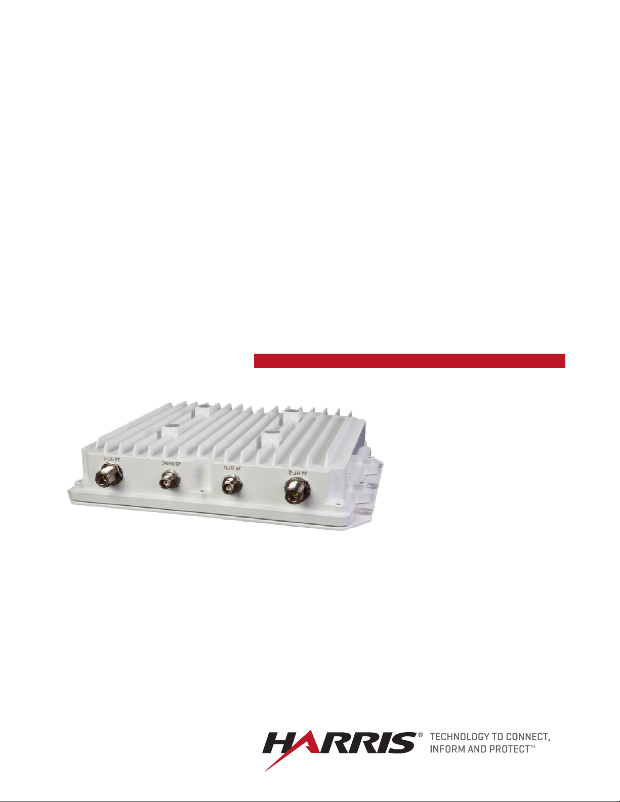
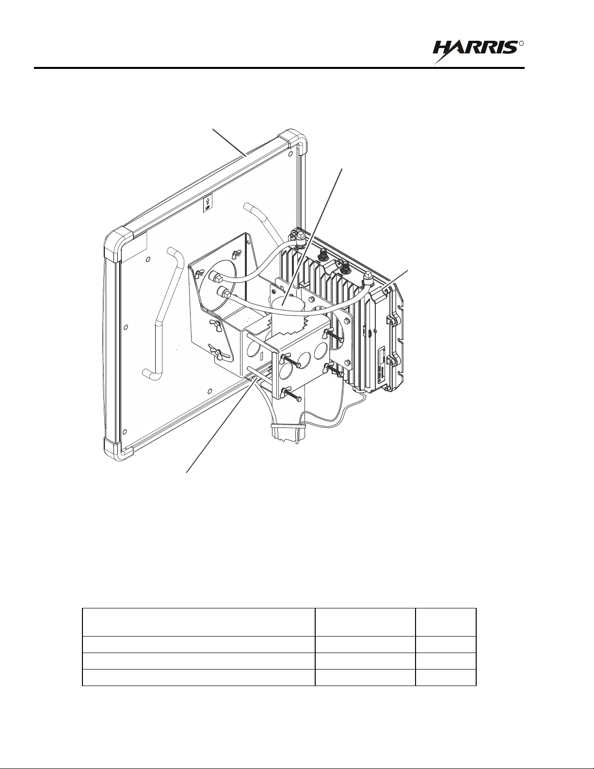
The RF-7800W-OU49x radio can be installed with various antennas.
Figure 1-1 shows a typical installation of the radio with the RF-7800W-AT201 One Foot MIMO Panel Antenna.
1-1
RF-7800W
R
CL-0426-4220-0001
HCLOS
RADIO
RF-7800W-AT201
ONE-FOOT ANTENNA
(PURCHASED SEPARATELY)
MAST OR TOWER PIPE
BRACKET AND RF CABLES
(PURCHASED SEPARATELY)
GENERAL INFORMATION
(PURCHASED SEPARATELY)
RF-7800W
Figure 1-1. RF-7800W HCLOS Radio Installed With One-Foot Panel MIMO Antenna
1.2.1 Ancillary Items
Refer to Table 1 -1. The ancillary items may be purchased separately.
Table 1-1. RF-7800W HCLOS Radio Ancillary Items
Item Name Part
Kit, Midspan Injector, Gigabit, PoE, All Regions 12069-3800-01 1
Quantity
Number
1-2
Bracket Assembly, Mounting, Radio Antenna 12069-3810-01 1
RF Coaxial Cable 12069-3940-A20 2

RF-7800W
R
GENERAL INFORMATION
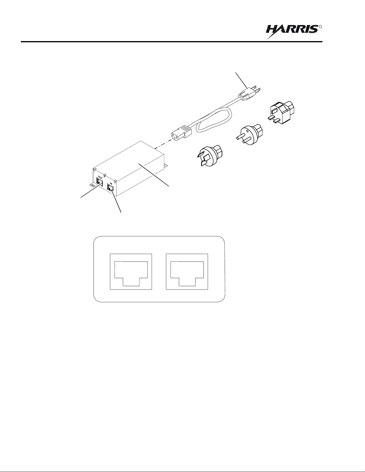
1.2.2 PoE Injector Kit
See Figure 1-2. The indoor-mounted Power over Ethernet (PoE) Injector is an in-line power injector that provides
operational power for the radio as well as connection to the network. AC power plug adapters are included for USA
National Electric Manufacturers Association (NEMA) 5-15R to Australia/New Zealand, UK, and Europe.
Figure 2-2 shows the PoE Injector connector interface.
1.2.3 Mast Mount Bracket
A bracket assembly (12069-3810-01) is included to mount the radio antenna to an existing mast or tower up to 4
inches (10.16 cm) in diameter.
1.2.4 RF Coaxial Cables
Two (2) 20-inch (51 cm) RF coaxial cables (12069-3940-A20) are included to connect the radio and antenna.
1-3
RF-7800W
R
IN
A
(USA)
OUT
(CONNECT TO
RF-7800W RADIO)
IN
(CONNECT TO
ETHERNET NETWORK)
PoE INJECTOR
A
ADAPTER
NEMA 5-15R TO
EUROPE CEE 7/7
ADAPTER
NEMA 5-15R TO
UK BS 1363
ADAPTER
OUT
(DATA AND POWER)
GENERAL INFORMATION
C POWER CABLE
USA NEMA 5-15R TO
USTRALIA/NEW ZEALAND
PoE INJECTOR PORTS - FRONT VIEW DETAIL
Figure 1-2. PoE Injector Kit - All Regions
(DATA)
CL-0426-4200-0019
1-4
RF-7800W
R
9.31 IN
(23.7 CM)
GENERAL INFORMATION
1.3 EQUIPMENT DESCRIPTION
The radio is housed in a weatherproof aluminum alloy case and is mounted outdoors to the optional mast mount
bracket. The main unit contains all of the RF and digital electronics. Power delivery is accomplished via an IEEE
802.3at PoE standard power injector.
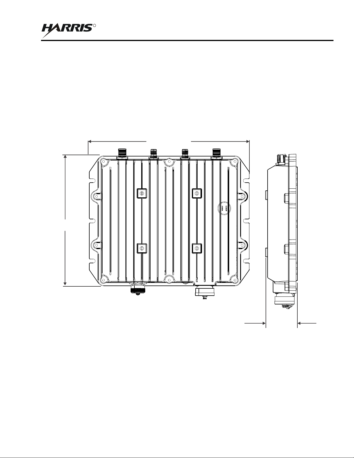
1.3.1 Radio Dimension and Weight Information
Figure 1-3 shows the dimensions of the RF-7800W HCLOS Radio. Refer to Table 1-2 for the dimensions and
weights.
11.45 IN (29.1 CM)
2.50 IN (6.4 CM)
CL-0426-4200-0002
Figure 1-3. RF-7800W HCLOS Radio Dimensions
1-5
RF-7800W
R
2.87 IN (7.3 CM)
10.92 IN
(27.7 CM)
3.93 IN
(10 CM)
3.93 IN (10 CM)
CL-0426-4200-0025
GENERAL INFORMATION
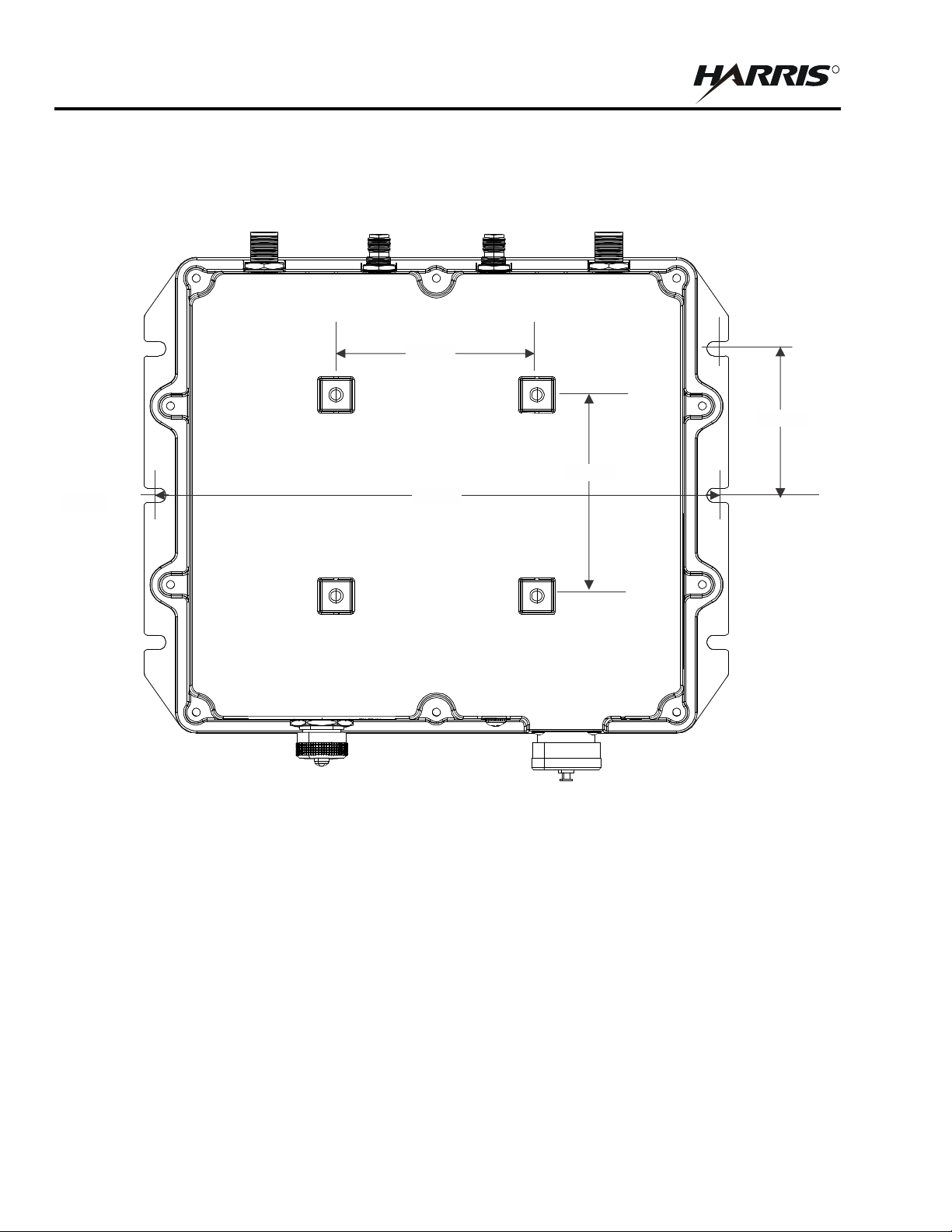
1.3.2 Radio Mounting Hole Pattern
Figure 1-4 shows the RF-7800W HCLOS radio mounting hole pattern.
1-6
Figure 1-4. RF-7800W HCLOS Radio Mounting Hole Pattern

RF-7800W
R
GENERAL INFORMATION
1.4 SPECIFICATIONS
Table 1- 2 provides specifications for the RF-7800W HCLOS Radio.
Table 1-2. RF-7800W HCLOS Radio Specifications
Function Specification
GENERAL
Frequency Range 5.725-5.875 GHz
Power Requirements IEEE 802.3at Compliant PSE, 30W Maximum
WIRELESS
Wireless Transmission Time Division Duplexing (TDD) Orthogonal Frequency Division Multiplexing
(ODFM), 2x2 MIMO Capable, Space-Time Coding (STC), Spatial Multiplexing
(SMX)
Uncoded Data Rate Up to 476 Mbps
Channel Size 5 MHz, 10 MHz, 20 MHz, 40 MHz
Channel Spacing Step Size is every 0.5 MHz
Receive Sensitivity -98 dBm best
Transmit Power 22 dBm Max per port
Modulation Binary Phase Shift Keying (BPSK), Quadrature Phase Shift Keying (QPSK), 16
Quadrature Amplitude Modulation (QAM), 64 QAM, 256 QAM
NETWORK
Network Connection 10/100/1000 BASE-T Ethernet
Management HTTP, HTTPS, Telnet, Secure Shell (SSH), SNMP v2c/v3
Quality of Service (QoS) 802.1p with 4 Priority Queues; strict priority queuing with tail drop
Virtual Local Area Network
802.1Q Management Tagging
(VLAN)
SECURITY
Encryption 128 and 256-bit AES, Traffic Flow Security (TFS)
Interference Control Adaptive Modulation, Automatic Transmit Power Control (ATPC), Dynamic
Frequency Selection (DFS)
MECHANICAL
Dimensions 11.45 W x 9.31 H x 2.50 D in (29.1 W x 23.7 H x 6.4 D cm)
Weight Less than 5.5 lbs (2.5 kg)
1-7

RF-7800W
R
WARNING
GENERAL INFORMATION
1.5 FCC NOTICES (FOR DEPLOYMENTS WITHIN THE USA)
a. Installation
The RF-7800W-OU49x must be installed by a qualified professional installer who is knowledgeable of
and follows local and national codes for electrical grounding and safety, and is knowledgeable of and
follows the local and regional regulatory RF requirements.
b. RF Exposure Warnings
To satisfy FCC RF exposure requirements for RF transmitting devices, the following distances should
be maintained between the antenna and persons during device operation.
Notice - FCC Recommended Safe Separation Distances (RF)
Frequency (GHz) Separation Distance
5.725 - 5.850 170 cm (66.93 in)
To ensure compliance, operation at closer than these distances is not recommended. The antenna used
for this transmitter must not be collocated in conjunction with any other antenna or transmitter.
c. FCC Information to Users (Part 15.105):
NOTE: This equipment has been tested and found to comply with the limits for a Class B digital device,
pursuant to part 15 of the FCC Rules. These limits are designed to provide reasonable protection against
harmful interference in a residential installation. This equipment generates, uses, and can radiate radio
frequency energy and, if not installed and used in accordance with the instructions, may cause harmful
interference to radio communications. However, there is no guarantee that interference will not occur
in a particular installation. If this equipment does cause harmful interference to radio or television
reception, which can be determined by turning the equipment off and on, the user is encouraged to try
to correct the interference by one or more of the following measures:
• Reorient or relocate the receiving antenna.
• Increase the separation between the equipment and receiver.
• Connect the equipment into an outlet on a circuit different from that to which the receiver is
connected.
• Consult the dealer or an experienced radio/TV technician for help.
d. FCC Information to Users (Part 15.21):
Changes or modifications not expressly approved by Harris
Corporation could void the user’s authority to operate the
equipment.
1-8

RF-7800W
R
SYSTEM INSTALLATION
CHAPTER 2
SYSTEM INSTALLATION
2.1 INTRODUCTION
Consider the following before installing a RF-7800W High Capacity Line of Sight (HCLOS) Radio system:
• Environmental and Line of Sight concerns
• Link Availability
• System Configuration
• Co-location
2.1.1 Environmental and Line of Sight Concerns
The RF-7800W is a microwave radio, which demands better Line of Sight (LOS) conditions than other radios that
operate with a lower frequency. Optical Line of Sight (OLOS) alone may not be adequate enough to maintain a
healthy link between radios. The radio operates at a lower power than other Harris radios, but high-gain antennas
give it the ability to link over many tens of kilometers in some situations. At these distances, weather and the
curvature of the Earth can become major factors affecting link quality. A thorough propagation study and analysis
using industry standard ITU recommended guidelines should be performed before deploying radios in an unknown
or unfamiliar location.
2.1.2 Link Availability
Harris provides a free tool to users that wish to perform a simple evaluation of a single RF-7800W radio link under
ideal environmental and terrain conditions. The Link Budget Tool (available via the Harris Premier site
https://rfcommpremier.harris.com
help users choose the right antenna for their specific installation.
2.1.3 System Configuration
There are two configuration types:
) provides a rudimentary calculation of annual Link Availability (Uptime) and can
• Simple Point to Point (SPTP) - Two RF-7800W radios are used, one as a Sector Controller (SC) and one as
a Subscriber Station (SS).
• Simple Point to Multipoint (SPMP) - Two or more RF-7800W radios are used, one as a Sector Controller
(SC) and the rest as Subscriber Stations (SS).
Some RF-7800W link configuration and statistics are split into downlink and uplink. The downlink direction always
refers to data or signals transmitted by the SC down to the SS. The uplink direction always refers to data or signals
transmitted by the SS up to the SC.
2.1.4 Co-location
Radio co-location on a single mast or tower system is sometimes unavoidable. A number of strategies can be
employed to reduce the possibility of interference between radios. Higher gain antennas typically have a narrower
beamwidth, which can help increase the signal to noise ratio (SNR) if they are not pointed in the same direction. If
possible, co-located radios should use operating frequencies that are at least one full channel width away from each
other.
2-1

RF-7800W
R
SYSTEM INSTALLATION
2.2 INSTALLATION REQUIREMENTS
Refer to Table 2- 1 . In preparation for installing a RF-7800W HCLOS Radio system, the following items that are not
included are required.
Table 2-1. Tools and Materials
Item Description
1 7/16” Open or Close Ended Wrench
2 7/16” Socket Wrench
3 #2 Drive Phillips-tip Screwdriver
4 Cable Ties, Zip Ties, or Tie-Wraps
5
Silicone Grease (Dow Corning DC-5 or similar
corrosion preventative compound)
6 Electrical Tape (3M Scotch Super 33+ or similar)
7
8
Polyurethane Sealant (Vulkem 116, Sikaflex 201, or
similar)
Ground Wire - 10 AWG min, with a 10/32” (M5) ring
terminal
These items are also not included, but are needed in order to maximize equipment performance:
• Outdoor rated, shielded Category 5e (or higher) Ethernet cable with shielded RJ-45 connectors. Amphenol
RJF6B backshells (key code 'A') should be added to any cables used to protect the radio's internal from
moisture. (Harris PN 12069-0030-Axxx and 12069-0031-Axxx)
• Dual-linear (V/H) polarized antennas in order to operate at full throughput capacity. (Harris PN RF-7800W-
AT 2X X )
The installation site should be free from major twist or sway under wind loading. A higher mounting location will
help guarantee better Line of Sight (LOS) conditions, but can increase the risk of damage due to lightning. The
mounting location should also provide a clear view of the sky for GPS, if required.
2.3 PRE-INSTALLATION CONFIGURATION
Time can be saved and hassle avoided by configuring all of the RF-7800W radios before they are permanently
installed. Two Ethernet cables and a computer with an Ethernet port are required for this step.
2.3.1 Connecting to a Radio
a. Connect an Ethernet cable between the J1 PoE port in the radio and the OUT port on the PoE injector,
allowing up to three (3) minutes for the radio to boot.
b. Connect an Ethernet cable between the IN port on the PoE injector and computer.
c. Configure the computer's IP address so that it is different than the radio's default IP address
(192.168.26.2), but also on the same subnet (255.255.255.0).
d. Open a web browser to the radio's address and log in using the default credentials (admin/admin).
2-2

R
2.3.2 Configure the Subscriber Stations
NOTE
a. Select Wireless Configuration and ensure that the Frequency and Channel Size are configured the same
on all linked radios.
b. Change the Tx Power, if necessary.
c. Select Apply & Save All.
d. Select System Configuration and ensure that each radio has a unique IP address so that they can be
individually accessible over the wireless link.
e. Change the IP Address.
f. Select Apply & Save All.
g. Perform the Wireless Configuration and System Configuration for all other SS radios in the system,
recording each radio's MAC address if using Normal Links as they will be needed when configuring the
SC radio. Otherwise, ensure that the STID and STID Password match those of the SC radio if using Link
Templates.
RF-7800W
SYSTEM INSTALLATION
STID Password defaults to “default”.
2.3.3 Configure the Sector Controller
a. Select Wireless Configuration.
b. Observe that only one of the radios in the system should be configured as a Sector Controller (SC).
c. Configure the Frequency and Channel Size the same on all linked radios.
d. Change the Tx Power, if necessary.
e. Select Apply & Save All.
f. Select System Configuration and ensure that each radio has a unique IP address so that they can be
individually accessible over the wireless link.
g. Change the IP Address.
h. Select Apply & Save All.
i. Select New Subscriber Link (or Configuration > Link for SPTP systems) under Provisioning.
j. Enter a name for the link as well as the unique MAC address of the remote radio if using Normal Links.
Otherwise, ensure that the STID and STID Password match those on the SS radio if using Link
Templates.
k. Select Apply.
l. Perform the Link Configuration for any other subscriber links, if using Normal Links or multiple Link
Templates.
m. Select Save All in the Navigation Menu once all links are added.
2-3

RF-7800W
R
SYSTEM INSTALLATION
2.4 INSTALLATION
2.4.1 Hardware Installation
a. Mounting the Radio
The radio's ancillary kit comes with a bracket that is designed to mount the radio and an antenna to a
vertical pipe or mast with a diameter of 1.5 to 4.0 inches. The radio can be mounted on either side of
the bracket but should be installed with the Ethernet port facing the ground (see Figure 2-1). 7/16” tools
(Items 1 & 2) are needed to assemble the bracket and install the radio.
b. Mounting the Antenna
Most of the antennas designed for use with the radio will mount to the front portion of the mounting
bracket. Support for other mounting styles like a vertical whip antenna can be achieved by swapping
out the front bracket with another design. The antenna bracket that comes in the ancillary kit is designed
to tilt the antenna through 45° of elevation about the horizon.
c. Lightning Protection (recommended)
Cables running down from equipment that is mounted on a roof, tower, or portable mast system provide
a path for lightning to surge into other equipment on the premise. A properly grounded lightning
protector installed at the bottom of the mast or at the entrance to a building can protect both personnel
and other equipment from damage due to lightning.
2-4
 Loading...