

Page 1

PUBLICATION NUMBER: 10515-0365-4200
JUNE 2017
Rev. C
RF-7800B-DU024 LAND PORTABLE
RF-7800B-VU104 LAND MOBILE
BROADBAND GLOBAL AREA
NETWORK TERMINAL
OPERATION
MANUAL
This information is controlled by the U.S. Department of Commerce Export Administration Regulations 15 CFR
730-774, ECCN EAR99. Information contained herein is property of Harris Corporation and may not be copied
or reproduced by any means, without prior written permission. Information contained herein is property of
Harris Corporation and may not be copied or reproduced by any means, without prior written permission.
Page 2

R
LIMITED ONE YEAR WARRANTY
HARRIS CORPORATION (COMMUNICATION SYSTEMS)
FROM HARRIS TO YOU - This warranty is extended to the original buyer and applies to all Harris Corporation equipment purchased and
employed for the service normally intended, except those products specifically excluded.
NOTE: Terms and conditions of the standard warranty may be superseded by the terms and conditions of your contract.
WHAT WE WILL DO - If your Harris Corporation equipment purchased from us fails in normal use because of a defect in workmanship or
materials within one year from the date of shipment, we will repair or replace (at our option) the equipment or part with new, reconditioned,
or remanufactured equipment or parts without charge to you, at our authorized repair center or factory.
WHAT YOU MUST DO - You must notify us promptly of a defect within one year from date of shipment. Assuming that Harris concurs that
the complaint is valid, and is unable to correct the problem without having the equipment shipped to Harris:
• Customers with equipment purchased for use outside the United States must obtain a Return Material Authorization (RMA)
Number for the return of the defective equipment or part to our factory in Rochester, NY, U.S.A., for repair or replacement.
You must prepay all transportation, insurance, duty and customs charges. We will pay for return to you of the repaired/
replaced equipment or part, C.I.F. destination; you must pay any duty, taxes or customs charges.
• Customers with equipment purchased for use in the United States must obtain an RMA number, properly pack, insure,
prepay the shipping charges and ship the defective equipment or part to our factory or to the Authorized Warranty Repair
Center indicated by us.
RMA may be obtained using our Premier Website https://tcpremier.harris.com
Shipping instructions will be provided with the RMA confirmation.
Harris Product Service: Phone (585) 242-3561, Toll-free (866) 264-8040, Fax: 585-242-4483
Harris will repair or replace the defective equipment or part and pay for its return to you, provided the repair or replacement is due to a
cause covered by this warranty.
WHAT IS NOT COVERED - We regret that we cannot be responsible for:
• Defects or failures caused by buyer or user abuse or misuse.
Units that have been misused, neglected, or damaged by accident.
• Defects or failures caused by unauthorized attempts to repair or alter the equipment in any way by persons other than Harris.
Includes units that have been disassembled
• Damage caused by leaking batteries
• Consequential damages incurred by a buyer or user from any cause whatsoever, including, but not limited to improper
packaging, transportation, non-Harris repair or service costs, downtime costs, costs for substituting equipment or loss of
anticipated profits or revenue.
• The performance of the equipment when used in combination with equipment not purchased from Harris.
• HARRIS MAKES NO OTHER WARRANTIES BEYOND THE EXPRESS WARRANTY AS CONTAINED HEREIN. ALL
EXPRESS OR IMPLIED WARRANTIES OF FITNESS FOR A PARTICULAR PURPOSE OR MERCHANTABILITY ARE
EXCLUDED.
SERVICE WARRANTY - Any repair service performed by Harris under this limited warranty is warranted to be free from defects in material
or workmanship for sixty days from date of repair. All terms and exclusions of this limited warranty apply to the service warranty.
IMPORTANT - Customers who purchased equipment must obtain an RMA before shipping the defective equipment to us. Failure to obtain
an RMA before shipment may result in a delay in the repair/replacement and return of your equipment.
IF YOU HAVE ANY QUESTIONS - Concerning this warranty, please refer to Harris Terms & Conditions of Repair at
http:///tcpremier.harris.com/pdf/general/10515-0003_tcm26-18726.pdf
10515-0002F
06/2017
Page 3

Page 4

PUBLICATION NUMBER: 10515-0365-4200
JUNE 2017
Rev. C
HARRIS CORPORATION COMMUNICATION SYSTEMS
1680 University Avenue Rochester, New York 14610-1887 USA
Tel: 585-244-5830. Fax: 585-242-4755. http://www.harris.com
R
RF-7800B-DU024 LAND PORTABLE
RF-7800B-VU104 LAND MOBILE
BROADBAND GLOBAL AREA
NETWORK TERMINAL
OPERATION MANUAL
Information and descriptions contained herein are the property of Harris Corporation. Such
information and descriptions may not be copied or reproduced by any means, or disseminated
or distributed without the express prior written permission of Harris Corporation,
Communication Systems, 1680 University Avenue, Rochester, New York 14610-1887.
Copyright 2017
By Harris Corporation
All Rights Reserved
Firmware Version 6.1.0.3
Page 5

Page 6

RF-7800B
R
TABLE OF CONTENTS
TABLE OF CONTENTS
Paragraph Page
CHAPTER 1 – GENERAL INFORMATION
1.1 SAFETY PRECAUTIONS . . . . . . . . . . . . . . . . . . . . . . . . . . . . . . . . . . . . . . . 1-1
1.2 PURPOSE OF THIS MANUAL. . . . . . . . . . . . . . . . . . . . . . . . . . . . . . . . . . . . 1-1
1.2.1 Acronyms . . . . . . . . . . . . . . . . . . . . . . . . . . . . . . . . . . . . . . . . . . . . . . . . . . . . 1-1
1.2.2 Warranty. . . . . . . . . . . . . . . . . . . . . . . . . . . . . . . . . . . . . . . . . . . . . . . . . . . . . 1-1
1.3 EQUIPMENT DESCRIPTION . . . . . . . . . . . . . . . . . . . . . . . . . . . . . . . . . . . . 1-1
1.3.1 RF-7800B-VU104 Land Mobile BGAN Terminal . . . . . . . . . . . . . . . . . . . . . . 1-2
1.3.2 RF-7800B-DU024 Land Portable BGAN Terminal . . . . . . . . . . . . . . . . . . . . . 1-3
1.3.3 USIM/SIM Card . . . . . . . . . . . . . . . . . . . . . . . . . . . . . . . . . . . . . . . . . . . . . . . 1-3
1.4 FEATURES . . . . . . . . . . . . . . . . . . . . . . . . . . . . . . . . . . . . . . . . . . . . . . . . . . 1-4
1.5 SPECIFICATIONS . . . . . . . . . . . . . . . . . . . . . . . . . . . . . . . . . . . . . . . . . . . . . 1-4
1.6 CONFIGURATIONS . . . . . . . . . . . . . . . . . . . . . . . . . . . . . . . . . . . . . . . . . . . . 1-6
1.7 BGAN NETWORK . . . . . . . . . . . . . . . . . . . . . . . . . . . . . . . . . . . . . . . . . . . . . 1-6
1.8 COMPATIBILITY . . . . . . . . . . . . . . . . . . . . . . . . . . . . . . . . . . . . . . . . . . . . . . 1-7
1.8.1 BGAN Compatible Radios . . . . . . . . . . . . . . . . . . . . . . . . . . . . . . . . . . . . . . . 1-7
1.8.2 Compatible Encryption Equipment . . . . . . . . . . . . . . . . . . . . . . . . . . . . . . . . . 1-8
1.8.3 Computer Requirements for Embedded Web Interface . . . . . . . . . . . . . . . . . 1-8
1.9 OPTIONAL ACCESSORIES . . . . . . . . . . . . . . . . . . . . . . . . . . . . . . . . . . . . . 1-8
1.9.1 RF-7800B-DU024 Options . . . . . . . . . . . . . . . . . . . . . . . . . . . . . . . . . . . . . . . 1-9
1.9.2 RF-7800B-VU104 Options . . . . . . . . . . . . . . . . . . . . . . . . . . . . . . . . . . . . . . . 1-9
CHAPTER 2 – SYSTEM SETUP AND TEARDOWN
2.1 ITEMS INCLUDED WITH RF-7800B BGAN TERMINAL . . . . . . . . . . . . . . . . 2-1
2.2 INSTALLATION GUIDELINES . . . . . . . . . . . . . . . . . . . . . . . . . . . . . . . . . . . . 2-2
2.2.1 Environmental . . . . . . . . . . . . . . . . . . . . . . . . . . . . . . . . . . . . . . . . . . . . . . . . 2-2
2.2.2 Dimension and Weight Information . . . . . . . . . . . . . . . . . . . . . . . . . . . . . . . . 2-3
2.2.3 Power Requirements . . . . . . . . . . . . . . . . . . . . . . . . . . . . . . . . . . . . . . . . . . . 2-3
2.2.4 Grounding. . . . . . . . . . . . . . . . . . . . . . . . . . . . . . . . . . . . . . . . . . . . . . . . . . . . 2-3
2.3 UNPACKING AND REPACKING . . . . . . . . . . . . . . . . . . . . . . . . . . . . . . . . . . 2-3
2.3.1 Unpacking . . . . . . . . . . . . . . . . . . . . . . . . . . . . . . . . . . . . . . . . . . . . . . . . . . . 2-3
2.3.2 Repacking . . . . . . . . . . . . . . . . . . . . . . . . . . . . . . . . . . . . . . . . . . . . . . . . . . . 2-3
2.4 BGAN TERMINAL SETUP . . . . . . . . . . . . . . . . . . . . . . . . . . . . . . . . . . . . . . . 2-3
2.4.1 Installing USIM in RF-7800B-DU024 . . . . . . . . . . . . . . . . . . . . . . . . . . . . . . . 2-4
2.4.2 Installing USIM in RF-7800B-VU104 . . . . . . . . . . . . . . . . . . . . . . . . . . . . . . . 2-6
2.5 INSTALLATION PROCEDURES . . . . . . . . . . . . . . . . . . . . . . . . . . . . . . . . . . 2-8
2.5.1 RF-7800B-VU104 Installation. . . . . . . . . . . . . . . . . . . . . . . . . . . . . . . . . . . . . 2-8
2.5.2 RF-7800B-DU024 Fixed/Semi-fixed Installation. . . . . . . . . . . . . . . . . . . . . . . 2-9
2.5.3 Cable Connections. . . . . . . . . . . . . . . . . . . . . . . . . . . . . . . . . . . . . . . . . . . . . 2-10
2.5.4 Protecting Connectors . . . . . . . . . . . . . . . . . . . . . . . . . . . . . . . . . . . . . . . . . . 2-11
2.6 INITIAL TURN-ON / CHECK . . . . . . . . . . . . . . . . . . . . . . . . . . . . . . . . . . . . . 2-12
2.6.1 Determining Ethernet IP address of BGAN Terminal . . . . . . . . . . . . . . . . . . . 2-12
i
Page 7

RF-7800B
R
TABLE OF CONTENTS
TABLE OF CONTENTS – Continued
Paragraph Page
CHAPTER 3 – OPERATION
3.1 INTRODUCTION . . . . . . . . . . . . . . . . . . . . . . . . . . . . . . . . . . . . . . . . . . . . . . 3-1
3.2 OPERATIONS TASK SUMMARY . . . . . . . . . . . . . . . . . . . . . . . . . . . . . . . . . 3-1
3.3 MAKE CABLE CONNECTIONS. . . . . . . . . . . . . . . . . . . . . . . . . . . . . . . . . . . 3-1
3.3.1 Data Connections. . . . . . . . . . . . . . . . . . . . . . . . . . . . . . . . . . . . . . . . . . . . . . 3-2
3.3.1.1 Connect Data by Ethernet . . . . . . . . . . . . . . . . . . . . . . . . . . . . . . . . . . . . . . . 3-2
3.3.1.2 Connect Data by USB . . . . . . . . . . . . . . . . . . . . . . . . . . . . . . . . . . . . . . . . . . 3-3
3.3.1.3 Connect Data by ISDN. . . . . . . . . . . . . . . . . . . . . . . . . . . . . . . . . . . . . . . . . . 3-4
3.3.1.4 Connect Data to Radio. . . . . . . . . . . . . . . . . . . . . . . . . . . . . . . . . . . . . . . . . . 3-4
3.3.2 Power Connections . . . . . . . . . . . . . . . . . . . . . . . . . . . . . . . . . . . . . . . . . . . . 3-5
3.3.2.1 Connect BGAN Terminal Power to Commercial Vehicle 12 VDC . . . . . . . . . 3-5
3.3.2.2 Connect BGAN Terminal Power to AC to DC Power Supply . . . . . . . . . . . . . 3-5
3.3.2.3 Connect BGAN Terminal Power to Battery . . . . . . . . . . . . . . . . . . . . . . . . . . 3-5
3.3.2.4 Connect BGAN Terminal Power to 26 VDC Power Supply . . . . . . . . . . . . . . 3-6
3.3.2.5 Connect RF-7800B-DU024 Power to BGAN Battery Box Kit. . . . . . . . . . . . . 3-7
3.4 USING RF-7800B-DU024 TERMINAL STAND . . . . . . . . . . . . . . . . . . . . . . . 3-8
3.5 RF-7800B-DU024 INITIAL SETTINGS AND TURN-ON . . . . . . . . . . . . . . . . 3-9
3.6 RF-7800B-VU104 INITIAL SETTINGS AND TURN-ON . . . . . . . . . . . . . . . . 3-10
3.7 BGAN SERVICES . . . . . . . . . . . . . . . . . . . . . . . . . . . . . . . . . . . . . . . . . . . . . 3-11
3.7.1 Obtaining a GPS Fix . . . . . . . . . . . . . . . . . . . . . . . . . . . . . . . . . . . . . . . . . . . 3-11
3.7.2 GPS and BGAN Registration . . . . . . . . . . . . . . . . . . . . . . . . . . . . . . . . . . . . . 3-11
3.7.3 ISDN Voice Telephony Services. . . . . . . . . . . . . . . . . . . . . . . . . . . . . . . . . . . 3-12
3.7.3.1 Dialing . . . . . . . . . . . . . . . . . . . . . . . . . . . . . . . . . . . . . . . . . . . . . . . . . . . . . . 3-12
3.7.3.2 Multi-Subscriber Numbering (MSN) . . . . . . . . . . . . . . . . . . . . . . . . . . . . . . . . 3-12
3.7.4 Data Services. . . . . . . . . . . . . . . . . . . . . . . . . . . . . . . . . . . . . . . . . . . . . . . . . 3-13
3.7.5 Virtual Private Network (VPN) Connections. . . . . . . . . . . . . . . . . . . . . . . . . . 3-13
CHAPTER 4 – CONFIGURATION
4.1 INTRODUCTION . . . . . . . . . . . . . . . . . . . . . . . . . . . . . . . . . . . . . . . . . . . . . . 4-1
4.2 CONFIGURATION CAPABILITIES . . . . . . . . . . . . . . . . . . . . . . . . . . . . . . . . 4-1
4.2.1 RF-7800B-VU104 Land Mobile BGAN Terminal . . . . . . . . . . . . . . . . . . . . . . 4-1
4.2.2 RF-7800B-DU024 Land Portable BGAN Terminal . . . . . . . . . . . . . . . . . . . . . 4-2
4.3 BGAN TERMINAL MODES OF OPERATION . . . . . . . . . . . . . . . . . . . . . . . . 4-2
4.3.1 NAT Mode . . . . . . . . . . . . . . . . . . . . . . . . . . . . . . . . . . . . . . . . . . . . . . . . . . . 4-2
4.3.2 Relay Mode . . . . . . . . . . . . . . . . . . . . . . . . . . . . . . . . . . . . . . . . . . . . . . . . . . 4-3
4.3.3 Bridge Mode. . . . . . . . . . . . . . . . . . . . . . . . . . . . . . . . . . . . . . . . . . . . . . . . . . 4-5
4.4 CONFIGURATION PARAMETERS . . . . . . . . . . . . . . . . . . . . . . . . . . . . . . . . 4-6
4.4.1 Configuration . . . . . . . . . . . . . . . . . . . . . . . . . . . . . . . . . . . . . . . . . . . . . . . . . 4-6
4.4.2 Registration, GPS, Properties . . . . . . . . . . . . . . . . . . . . . . . . . . . . . . . . . . . . 4-9
4.4.3 Connect to Network . . . . . . . . . . . . . . . . . . . . . . . . . . . . . . . . . . . . . . . . . . . . 4-11
4.4.3.1 Activating a Network Connection . . . . . . . . . . . . . . . . . . . . . . . . . . . . . . . . . . 4-11
4.4.3.2 Activating Multiple Network Connections. . . . . . . . . . . . . . . . . . . . . . . . . . . . 4-13
4.4.4 Automatic Network Connections . . . . . . . . . . . . . . . . . . . . . . . . . . . . . . . . . . 4-13
ii
Page 8

RF-7800B
R
TABLE OF CONTENTS
TABLE OF CONTENTS – Continued
Paragraph Page
CHAPTER 4 – CONFIGURATION - CONTINUED
4.4.4.1 Automatic Network Connections Settings for TE with Static IP Address . . . . 4-15
4.4.4.2 Automatic Network Connections Settings for TE using DHCP Assigned IP
Address . . . . . . . . . . . . . . . . . . . . . . . . . . . . . . . . . . . . . . . . . . . . . . . . . . 4-15
4.4.5 ISDN Setup . . . . . . . . . . . . . . . . . . . . . . . . . . . . . . . . . . . . . . . . . . . . . . . . . . 4-16
4.4.6 Usage Report . . . . . . . . . . . . . . . . . . . . . . . . . . . . . . . . . . . . . . . . . . . . . . . . . 4-17
4.4.7 Antenna Status . . . . . . . . . . . . . . . . . . . . . . . . . . . . . . . . . . . . . . . . . . . . . . . . 4-18
4.5 UPGRADING THE BGAN TERMINAL SOFTWARE . . . . . . . . . . . . . . . . . . . 4-21
CHAPTER 5 – SCHEDULED MAINTENANCE
5.1 PREVENTIVE MAINTENANCE . . . . . . . . . . . . . . . . . . . . . . . . . . . . . . . . . . . 5-1
5.2 CORRECTIVE MAINTENANCE. . . . . . . . . . . . . . . . . . . . . . . . . . . . . . . . . . . 5-1
5.2.1 Troubleshooting Procedures . . . . . . . . . . . . . . . . . . . . . . . . . . . . . . . . . . . . . 5-2
5.2.1.1 Power-on BIT Faults. . . . . . . . . . . . . . . . . . . . . . . . . . . . . . . . . . . . . . . . . . . . 5-2
5.2.1.2 Operator-Initiated BIT Faults . . . . . . . . . . . . . . . . . . . . . . . . . . . . . . . . . . . . . 5-2
5.2.1.3 Run-Time Faults . . . . . . . . . . . . . . . . . . . . . . . . . . . . . . . . . . . . . . . . . . . . . . . 5-2
5.2.1.4 Non-BIT Faults . . . . . . . . . . . . . . . . . . . . . . . . . . . . . . . . . . . . . . . . . . . . . . . . 5-2
5.3 BATTERIES . . . . . . . . . . . . . . . . . . . . . . . . . . . . . . . . . . . . . . . . . . . . . . . . . . 5-7
5.3.1 Battery Life . . . . . . . . . . . . . . . . . . . . . . . . . . . . . . . . . . . . . . . . . . . . . . . . . . . 5-7
5.3.2 Battery Safety. . . . . . . . . . . . . . . . . . . . . . . . . . . . . . . . . . . . . . . . . . . . . . . . . 5-7
5.3.3 Rechargeable Battery Packs . . . . . . . . . . . . . . . . . . . . . . . . . . . . . . . . . . . . . 5-8
5.3.4 Disposing of Lithium Batteries . . . . . . . . . . . . . . . . . . . . . . . . . . . . . . . . . . . . 5-8
APPENDIX A - TECHNICAL INFORMATION
A.1 CHASSIS CONNECTOR PINOUT DATA. . . . . . . . . . . . . . . . . . . . . . . . . . . . A-1
A.1.1 Mating Connectors . . . . . . . . . . . . . . . . . . . . . . . . . . . . . . . . . . . . . . . . . . . . . A-2
APPENDIX B - GLOSSARY
B.1 GLOSSARY . . . . . . . . . . . . . . . . . . . . . . . . . . . . . . . . . . . . . . . . . . . . . . . . . . B-1
iii
Page 9

RF-7800B
R
TABLE OF CONTENTS
LIST OF FIGURES
Figure Page
1-1 RF-7800B-VU104 Land Mobile BGAN Terminal . . . . . . . . . . . . . . . . . . . . . . 1-2
1-2 RF-7800B-DU024 Land Portable BGAN Terminal . . . . . . . . . . . . . . . . . . . . . 1-3
1-3 BGAN Worldwide Coverage. . . . . . . . . . . . . . . . . . . . . . . . . . . . . . . . . . . . . . 1-7
2-1 Items Included with RF-7800B-VU104. . . . . . . . . . . . . . . . . . . . . . . . . . . . . . 2-1
2-2 Items Included with RF-7800B-DU024. . . . . . . . . . . . . . . . . . . . . . . . . . . . . . 2-2
2-3 Accessing the USIM Card Holder on RF-7800B-DU024 . . . . . . . . . . . . . . . . 2-4
2-4 Opening the USIM Card Holder on RF-7800B-DU024 . . . . . . . . . . . . . . . . . 2-5
2-5 Placing the USIM Card in Holder on RF-7800B-DU024 . . . . . . . . . . . . . . . . 2-5
2-6 USIM Card Located in Holder on RF-7800B-DU024 . . . . . . . . . . . . . . . . . . 2-5
2-7 Accessing the USIM Card Holder and Drain Holes on RF-7800B-VU104 . . . 2-7
2-8 Placing the USIM Card in Holder on RF-7800B-VU104. . . . . . . . . . . . . . . . . 2-7
2-9 Pole Mount Option . . . . . . . . . . . . . . . . . . . . . . . . . . . . . . . . . . . . . . . . . . . . . 2-9
2-10 Fixed Mount Option . . . . . . . . . . . . . . . . . . . . . . . . . . . . . . . . . . . . . . . . . . . . 2-10
2-11 Cabling Options . . . . . . . . . . . . . . . . . . . . . . . . . . . . . . . . . . . . . . . . . . . . . . . 2-11
3-1 RF-7800B-VU104 Connectors . . . . . . . . . . . . . . . . . . . . . . . . . . . . . . . . . . . . 3-1
3-2 RF-7800B-DU024 Connectors . . . . . . . . . . . . . . . . . . . . . . . . . . . . . . . . . . . . 3-2
3-3 BGAN Ethernet Cable, 12043-0833-A010 . . . . . . . . . . . . . . . . . . . . . . . . . . . 3-2
3-4 Standalone Ethernet and ISDN Cable, 12043-0834-A010 (Optional) . . . . . . 3-3
3-5 Standalone USB and ISDN Cable, 12043-0836-A010 (Optional) . . . . . . . . . 3-3
3-6 Standalone ISDN Cable, 12043-0835-A010 (Optional) . . . . . . . . . . . . . . . . . 3-4
3-7 BGAN to Radio Black Ethernet Cable, 12043-0830-A006 (Optional) . . . . . . 3-4
3-8 BGAN to Radio Black Ethernet and ISDN Cable, 12043-0831-A006 (Optional) 3-4
3-9 BGAN, DC Power to Vehicle 12 VDC, 12043-0843-A015 . . . . . . . . . . . . . . . 3-5
3-10 BGAN, AC to DC Power Supply Assembly, 12043-0894-A1 . . . . . . . . . . . . . 3-5
3-11 Cable Assembly, BGAN DC Power to 2 Leads, 12043-0896-A0xx . . . . . . . . 3-5
3-12 Cable Assembly, BGAN DC Power to 4 Leads, 12043-0890-A0xx . . . . . . . . 3-6
3-13 AC/DC Power Supply Cable (RF-505X-PS), 12043-0891-A0xx . . . . . . . . . . 3-6
3-14 BGAN DC Power to 26 VDC/Remote On/Off, 12043-0892-A0xx . . . . . . . . . 3-6
3-15 BGAN DC Power to Battery Box Cable, 12043-0850-A006. . . . . . . . . . . . . . 3-7
3-16 Battery Box Kit, 12091-4010-01. . . . . . . . . . . . . . . . . . . . . . . . . . . . . . . . . . . 3-7
3-17 Open RF-7800B-DU024 Terminal Stand . . . . . . . . . . . . . . . . . . . . . . . . . . . . 3-8
3-18 Slide Out Stabilizer. . . . . . . . . . . . . . . . . . . . . . . . . . . . . . . . . . . . . . . . . . . . . 3-9
3-19 RF-7800B-DU024 ON, OFF, or ON with Audio Switch . . . . . . . . . . . . . . . . . 3-10
4-1 NAT Mode Connections . . . . . . . . . . . . . . . . . . . . . . . . . . . . . . . . . . . . . . . . . 4-2
4-2 Relay Mode Connections . . . . . . . . . . . . . . . . . . . . . . . . . . . . . . . . . . . . . . . . 4-3
4-3 Bridge Mode Connections . . . . . . . . . . . . . . . . . . . . . . . . . . . . . . . . . . . . . . . 4-5
4-4 BGAN Terminal Configuration . . . . . . . . . . . . . . . . . . . . . . . . . . . . . . . . . . . . 4-8
4-5 BGAN Terminal Configuration Detail . . . . . . . . . . . . . . . . . . . . . . . . . . . . . . . 4-9
4-6 BGAN Terminal Properties . . . . . . . . . . . . . . . . . . . . . . . . . . . . . . . . . . . . . . . 4-10
4-7 BGAN Terminal Network Connections . . . . . . . . . . . . . . . . . . . . . . . . . . . . . . 4-12
4-8 BGAN Terminal IP Automatic Network Connections . . . . . . . . . . . . . . . . . . . 4-14
4-9 BGAN Terminal ISDN Properties . . . . . . . . . . . . . . . . . . . . . . . . . . . . . . . . . . 4-16
4-10 BGAN Terminal Usage Report . . . . . . . . . . . . . . . . . . . . . . . . . . . . . . . . . . . . 4-18
4-11 BGAN Terminal Antenna Status . . . . . . . . . . . . . . . . . . . . . . . . . . . . . . . . . . . 4-19
4-12 BGAN Terminal Upgrader . . . . . . . . . . . . . . . . . . . . . . . . . . . . . . . . . . . . . . . 4-22
4-13 BGAN Terminal Upgrade Complete . . . . . . . . . . . . . . . . . . . . . . . . . . . . . . . . 4-23
A-1 RF-7800B Data and Power Connector Pinouts . . . . . . . . . . . . . . . . . . . . . . . A-1
iv
Page 10

RF-7800B
R
TABLE OF CONTENTS
LIST OF TABLES
Table Page
1-1 RF-7800B BGAN Terminal Specifications . . . . . . . . . . . . . . . . . . . . . . . . . . . 1-4
4-1 Antenna Status ATB State . . . . . . . . . . . . . . . . . . . . . . . . . . . . . . . . . . . . . . . 4-19
4-3 ABIT Test Results. . . . . . . . . . . . . . . . . . . . . . . . . . . . . . . . . . . . . . . . . . . . . . 4-20
4-2 Satellite Frequencies . . . . . . . . . . . . . . . . . . . . . . . . . . . . . . . . . . . . . . . . . . . 4-20
5-1 Daily Preventive Maintenance Checks and Services . . . . . . . . . . . . . . . . . . . 5-1
5-2 Weekly Preventive Maintenance Checks and Services . . . . . . . . . . . . . . . . . 5-1
5-3 Run-Time BIT Faults, Descriptions, and Corrective Action . . . . . . . . . . . . . . 5-2
5-4 Non-BIT Troubleshooting . . . . . . . . . . . . . . . . . . . . . . . . . . . . . . . . . . . . . . . . 5-3
A-1 DATA . . . . . . . . . . . . . . . . . . . . . . . . . . . . . . . . . . . . . . . . . . . . . . . . . . . . . . . A-1
A-2 POWER . . . . . . . . . . . . . . . . . . . . . . . . . . . . . . . . . . . . . . . . . . . . . . . . . . . . . A-1
A-3 Connectors and Mating Connector Part Numbers . . . . . . . . . . . . . . . . . . . . . A-2
v
Page 11

RF-7800B
R
TABLE OF CONTENTS
This page intentionally left blank.
vi
Page 12

RF-7800B
R
SAFETY SUMMARY
SAFETY SUMMARY
1. INTRODUCTION
All operators and maintenance personnel must observe the following safety precautions during operation and
maintenance of this equipment. Specific warnings and cautions are provided in the manual and at the end of this
Safety Summary. Warnings, Cautions, and Notes appear before various steps in the manual and will be used as
follows:
• WARNING Used when injury or death to personnel and damage to equipment is possible
• CAUTION Used when there is a possibility of damage to equipment
• NOTE Used to alert personnel to a condition that requires emphasis
2. PERSONNEL AND EQUIPMENT SAFETY
Basic safety precautions consider factors involved in protecting personnel from injury or death. Electrical,
mechanical, thermal, electromagnetic radiation (EMR), or chemical hazards are the most common types of hazards
found in electronic equipment. The following are types of hazards that may exist:
ELECTRICAL Hazardous voltage and current levels may exist throughout the equipment. Contact
with these hazards could cause electrocution, electrical shock, burns, or injury due
to involuntary reflexes of the body.
THERMAL Burn hazards may exist in the equipment that could cause personal injuries and/or
serious equipment damage. Internal surfaces of the equipment may be in excess of
65°C, the point at which personnel could be burned. Extreme caution should be used
when working with any hot assemblies (for example, power supply or power
amplifier assemblies). Physical injury or damage may result to personnel and/or
equipment as a result of a reflex action to a burn.
EMR Overexposure to electromagnetic radiation from amplified radio frequencies
may produce a health hazard.
3. OPERATIONAL AND MAINTENANCE SAFETY GUIDELINES
Good safety discipline is critical to prevent injury to personnel. All other safety measures are useless if personnel
do not observe the safety precautions and do not follow safety disciplines. Once aware of a hazard, personnel should
ensure that all other personnel are aware of the hazard. The following basic safety disciplines are stressed:
a. Read a procedure entirely before performing it. Personnel must always perform each assigned task in a
safe manner.
b. Prior to applying equipment power after maintenance, personnel must ensure that all unsecured hand
tools and test equipment are disconnected from the serviced/maintained equipment and properly stored.
c. Power to the equipment must be removed before a piece of equipment is removed.
d. Extreme care must be used when adjusting or working on operating equipment. Voltages in excess of
70 V or current sources in excess of 25 A are covered with barriers. Barriers include warning
information about the hazard encountered upon barrier removal.
vii
Page 13

RF-7800B
R
SAFETY SUMMARY
e. Personnel must react when someone is being electrically shocked. Perform the following steps:
1. Shut off power.
2. Call for help.
3. Administer first aid if qualified.
Under no circumstances should a person come directly in contact with the body unless the power has
been removed. When immediate removal of the power is not possible, personnel must use a non-conductive material to try to jolt or pry the body away from the point of shock.
f. Personnel should work with one hand whenever possible to prevent electrical current from passing
through vital organs of the body. In addition, personnel must never work alone. Someone must be
available in the immediate area to render emergency first aid, if necessary.
g. Lifting can cause injury. Items weighing more than 37 pounds must be lifted by two or more people.
h. Some electrolytic capacitors contain aluminum oxide or tantalum. If connected incorrectly, the
capacitor will explode when power is applied. Extreme care must be used when replacing and
connecting these capacitors. The capacitor terminals must always be connected using the correct
polarity: positive to positive and negative to negative.
The next section contains general safety precautions not directly related to specific procedures or equipment. These
precautions are oriented toward the maintenance technician. However, all personnel must understand and apply
these precautions during the many phases of operation and maintenance of the equipment. The following
precautions must be observed:
EQUIPMENT USERS
User must be a skilled person. Designated users should not be exposed to conditions that could cause pain
or injury, nor intentionally caused said conditions.
DO NOT SERVICE EQUIPMENT ALONE
Never work on electrical equipment unless another person familiar with the operation and hazards of the
equipment is near. When the maintenance technician is aided by operators, ensure that operators are aware
of the hazards.
GROUNDING
Always ensure that all equipment and assemblies are properly grounded when operating or servicing.
TURN OFF POWER AND GROUND CAPACITORS
Whenever possible, power to equipment should be turned off before beginning work on the equipment. Be
sure to ground all capacitors that are potentially dangerous.
KEEP AWAY FROM LIVE CIRCUITS
Operators and maintainers must observe all safety regulations at all times. Do not change components or
make adjustments inside equipment with a high voltage supply on unless required by the procedure. Under
certain conditions, dangerous potentials may exist in circuits with power controls off, due to charges
retained by capacitors.
viii
Page 14

RF-7800B
R
SAFETY SUMMARY
DO NOT BYPASS INTERLOCKS
Do not bypass any interlocks unnecessarily. If it is necessary to employ an interlock bypass for equipment
servicing, use extreme care not to come in contact with hazardous voltages.
RADIATION HAZARD
Operators must keep a minimum required clearance of 1 m away from the equipment during operation.
USE CARE HANDLING HEAVY EQUIPMENT
Never attempt to lift large assemblies or equipment without knowing their weight. Use enough personnel or
a mechanical lifting device to properly handle the item without causing personal injury.
HEED WARNINGS AND CAUTIONS
Specific warnings and cautions are provided to ensure the safety and protection of personnel and equipment.
Be familiar with and strictly follow all warnings and cautions on the equipment and in technical manuals.
PROTECTIVE EYEWEAR
All personnel must wear protective eyewear when servicing or maintaining equipment. Protective eyewear
must be worn at all times when using tools.
4. PROTECTION OF STATIC-SENSITIVE DEVICES
Diode input-protection is provided on all static-sensitive devices. This protection is designed to guard against
adverse electrical conditions such as electrostatic discharge. Although most static-sensitive devices contain
protective circuitry, several precautionary steps should be taken to avoid the application of potentially damaging
voltages to the inputs of the device.
To protect static-sensitive devices from damage, the following precautions should be observed.
a. Keep all static-sensitive devices in their protective packaging until needed. This packaging is
conductive and should provide adequate protection for the device. Storing or transporting these devices
in conventional plastic containers could be destructive to the device.
b. Disconnect power prior to insertion or extraction of these devices. This also applies to PWBs containing
such devices.
c. Double check test equipment voltages and polarities prior to conducting any tests.
d. Avoid contact with the leads of the device. The component should always be handled carefully by the
ends or side opposite the leads.
ix
Page 15

RF-7800B
R
SAFETY SUMMARY
e. Avoid contact between PWB circuits or component leads and synthetic clothing.
f. Use only soldering irons and tools that are properly grounded. Ungrounded soldering tips or tools can
destroy these devices. SOLDERING GUNS MUST NEVER BE USED
.
5. FCC COMPLIANCE
This device conforms to the FCC rules. Any changes or modifications to Harris Corporations equipment, not
expressly approved by Harris Corporation could void the user's authority to operate the equipment.
To comply with FCC RF exposure requirements, this device must be operated with a minimum separation distance
of 20 cm or more from a person's body. Other operating configurations should be avoided.
This device complies with Part 15 of the FCC Rules. Operation is subject to the following two conditions; (1) this
device may not cause harmful interference, and (2) this device must accept any interference received, including
interference that may cause undesired operation.
6. DECLARATION OF CONFORMITY
Harris Corporation of Rochester NY, USA, declares under our sole responsibility that the product Harris RF-7800BVU104 and RF-7800B-DU024 Satellite IP Terminal to which this declaration relates, is in conformity with the
following standards and/or other normative documents:
ROHS Directive 2011-65-EU, IEC/EN 62368-1:2014, EN 301 444 V2.1.2 (2016-11), EN 301 489-1 V2.1.1 (2017-
02), EN 301 489-20 V1.2.1 (2002-11), EN 62311:2008.
We hereby declare that all essential radio test suites have been carried out and that the above named product is in
conformity to all the essential requirements of Radio Equipment Directive (RED) 2014/53/EU
The technical documentation relevant to the above equipment will be held at:
Harris Corporation 1680 University Avenue Rochester, New York 14610
7. EUROPEAN UNION WASTE ELECTRICAL AND ELECTRONIC EQUIPMENT DIRECTIVES
The European Union (EU) directive on waste electrical and electronic equipment mandates recycling of electrical
and electronic equipment throughout the EU by August 13, 2005.
Unless otherwise noted, all products, assemblies, and sub-assemblies manufactured by Harris and its sub-contractors
will be compliant with this directive and any subsequent revisions or amendments. This product carries the WEEE
Directive 2012/19/EU label below to demonstrate compliance.
For addition information, contact Harris Corporation at: www.harris.com.
x
Page 16

RF-7800B
R
RF-7800B-DU024 LAND PORTABLE
RF-7800B-VU104 LAND MOBILE
BROADBAND GLOBAL AREA
NETWORK TERMINAL
OPERATION MANUAL
Page 17

RF-7800B
R
This page intentionally left blank.
Page 18

RF-7800B
R
GENERAL INFORMATION
CHAPTER 1
GENERAL INFORMATION
1.1 SAFETY PRECAUTIONS
All safety precautions necessary for the protection of personnel and equipment are cross-referenced in the following
list. The WARNING or CAUTION is referenced to the paragraph number where it is used in the manual, and a brief
subject phrase indicating the content is provided. Read these items in their entirety before performing the referenced
procedure.
• WARNING - Paragraph 2.2.1 - Do not operate the BGAN terminal during electrical storms.
• WARNING - Paragraph 2.2.1 - Never use the BGAN terminal where blasting work is in progress.
• CAUTION - Paragraph 2.2.1 - Avoid placing BGAN terminal near any source of heat such as an open flame.
• CAUTION - Paragraph 3.5 - Do not stand in front of the BGAN terminal.
• WARNING - Paragraph 5.3.3 - Do not overcharge, short circuit, incinerate, or mutilate rechargeable
batteries.
• WARNING - Paragraph 5.3.4 - Do not dispose of batteries in uncontrolled trash, as batteries may contain
hazardous materials.
1.2 PURPOSE OF THIS MANUAL
This operation manual provides operating instructions, as well as technical information required to support Level I
(operator) Maintenance of RF-7800B Broadband Global Area Network (BGAN) Terminals (referred to throughout
this manual as BGAN terminal).
1.2.1 Acronyms
All acronyms used are contained in the Glossary at the back of this manual. Refer to Appendix B.
1.2.2 Warranty
For warranty information, refer to the inside front cover of this manual.
1.3 EQUIPMENT DESCRIPTION
The Harris RF-7800B Land Mobile and Land Portable BGAN Terminals provide a high-performance Satellite
Communications (SATCOM) solution with reliable voice and broadband data connectivity for Beyond-Line-ofSight (BLOS) SATCOM-on-the-Move (SOTM) and SATCOM-on-the-Quick-Halt (SOQH) applications. The
BGAN SATCOM spectrum (L-Band) utilizes the International Marine/Maritime Satellite (INMARSAT) 4
constellation, providing wideband Internet Protocol (IP) data throughput up to 492 kbps. These high data throughput
backbone links can interconnect warfighter tactical networks to Tactical Operation Centers (TOC) as well as beyond
line of sight vehicles or regional headquarters.
As a standalone device integrated into an existing network infrastructure, the BGAN terminals allow an Integrated
Services Digital Network (ISDN)-capable device to be plugged in for circuit switched mode use across the BGAN
network. This ISDN interface provides the ability to connect directly to the Public Switched Telephone Network
(PSTN) for telephony and data communications. This interface also provides the ability to connect Secure Terminal
Equipment (STE) directly to the BGAN terminal for secure telephone calls.
1-1
Page 19

RF-7800B
R
GENERAL INFORMATION
RF-7800B BGAN terminal products ensure a seamless tactical network-centric BLOS connectivity interface to
existing Falcon III tactical networks. When the AN/PRC-117G or RF-7800M-MP manpack radio is set up as a
BGAN gateway using a BGAN-enabled preset, the BGAN terminal provides BLOS range extension of data
networking capabilities through simultaneous operation with mobile wideband networked line-of-sight (LOS)
nodes. The Falcon III radios remote control the BGAN terminals to automatically create a connection to the
INMARSAT network, providing a fully integrated end-to-end IP data network for assured and secured
communications.
BGAN terminals can be configured and actively controlled via an embedded web-based interface. The web interface
is used to configure the BGAN terminal to meet system architecture requirements, including all IP networking
properties, automatic network connections, inactivity timers and ISDN properties. BGAN satellite connections can
be initiated and monitored through the web interface. Active connection status is provided on every page. Network
traffic usage is tracked in the amount of megabytes (Background Mode) and minutes (Streaming Mode), both on a
mission basis as well as through the BGAN terminal’s lifetime. Overall BGAN terminal status and version
information may be viewed through the web interface.
1.3.1 RF-7800B-VU104 Land Mobile BGAN Terminal
The Harris RF-7800B-VU104 Land Mobile BGAN Terminal is a Class 10 BGAN SOTM Terminal that provides
data rates of up to 492 kbps while on the move. See Figure 1-1. The BGAN terminal will send and receive IP packet
data via the Ethernet and Universal Serial Bus (USB) simultaneously with circuit switched telephony and data via
the ISDN interface over the INMARSAT BGAN satellite network.
RF-7800B-VU104 may be permanently mounted on a vehicle and is capable of operating at speeds of up to 70 mph.
Continuous tracking with the INMARSAT satellite is provided to achieve successful communications. Full network
connectivity is uninterrupted when vehicular velocity of motion is up to 100 degrees per second, and vehicular
acceleration is up to 100 degrees per second squared in both azimuth and elevation, with simultaneous random pitch
and roll.
CL-0365-4200-0001
Figure 1-1. RF-7800B-VU104 Land Mobile BGAN Terminal
1-2
Page 20
RF-7800B
R
GENERAL INFORMATION
1.3.2 RF-7800B-DU024 Land Portable BGAN Terminal
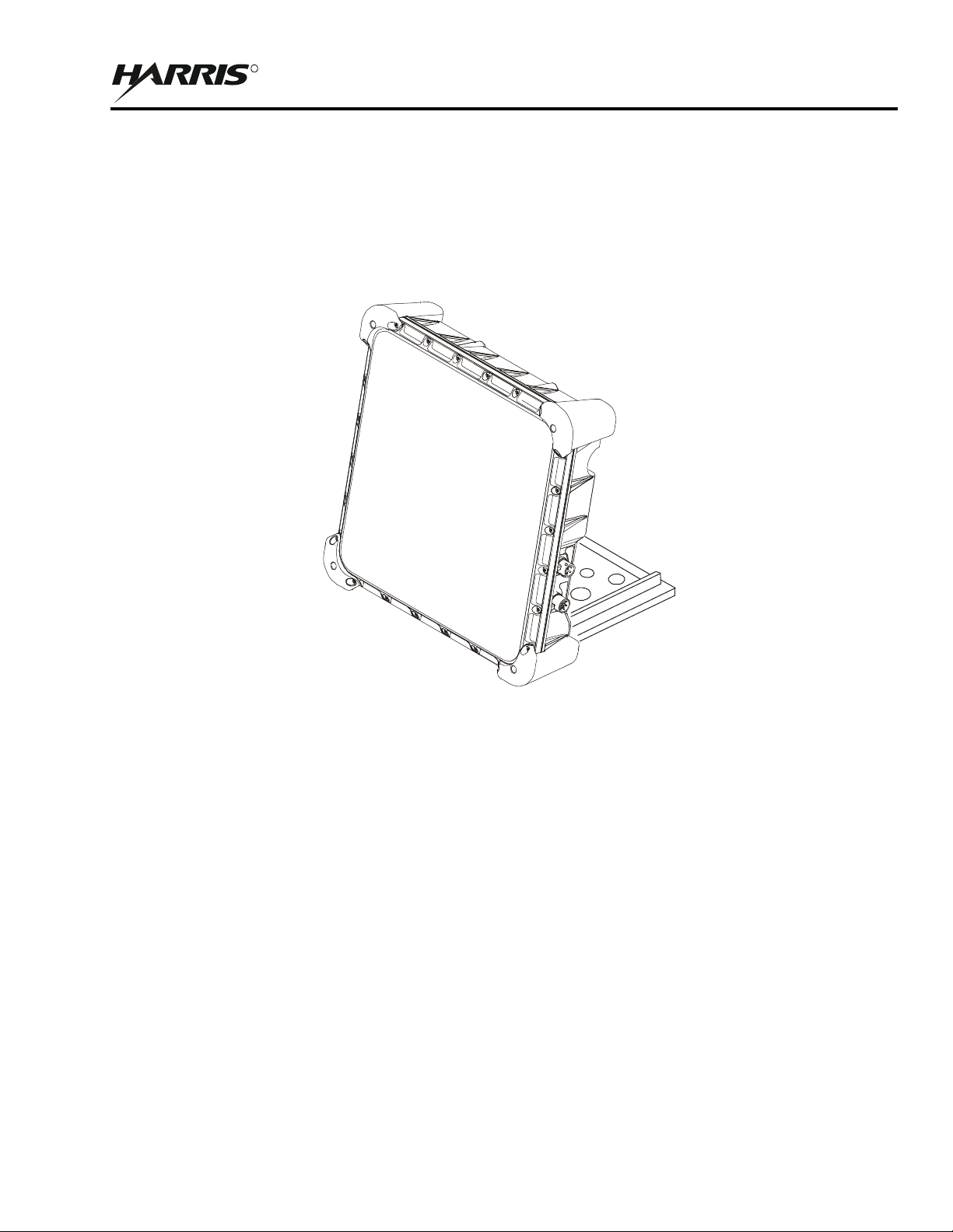
The RF-7800B-DU024 Land Portable BGAN Terminal is a Class 2 BGAN Land Portable Terminal that provides
data rates of up to 432 kbps. See Figure 1-2. This BGAN terminal is designed for operation in harsh environmental
conditions. RF-7800B-DU024 is a manually pointed antenna system capable of rapid deployment for sending and
receiving data once pointed at the satellite.
CL-0365-4200-0002
Figure 1-2. RF-7800B-DU024 Land Portable BGAN Terminal
1.3.3 USIM/SIM Card
A Subscriber Identity Module (SIM) contains an identity that uniquely identifies a subscriber of the Universal
Mobile Telecommunications System (UMTS). It stores subscription and subscriber related information. The UMTS
SIM (USIM) card must be installed for any operation of a BGAN terminal except for emergency calling.
Access to the USIM, and therefore to the BGAN system, may be restricted to an authorized user or number of users,
using the USIM Personal Identification Number (PIN). The PIN is stored securely in the USIM. The user enters the
PIN using the embedded web-based interface or the Falcon III Manpack radio front panel.
The USIM personalization feature ensures that access to a BGAN terminal or other user equipment is restricted to
an authorized USIM. The USIM and the BGAN terminal share a PIN stored securely in the USIM and the BGAN
terminal. If a USIM fails to prove its knowledge of the PIN, it is denied access to the BGAN terminal. If the USIM
is not detected during operation, the BGAN terminal will deactivate any active Network Connection, detach from
the network, and enter a "NO SIM" operational mode. The BGAN terminal must be restarted to detect a new or
replaced USIM. Refer to Paragraph 2.4.
1-3
Page 21

RF-7800B
R
GENERAL INFORMATION
1.4 FEATURES
Features and benefits of the BGAN terminal are:
• Global System for Mobile Communications (GSM) / General Packet Radio Service (GPRS) / UMTS IP-
based services
• Full IP compatibility for e-mail, File Transfer Protocol (FTP), web browsing, Virtual Private Network
(VPN), and so forth.
• Ability to work in multiple modes:
− Network Address Translation (NAT) Mode: for direct computer(s) connection
− Relay Mode: for direct router connection
− Bridge Mode: for direct Harris radio connection
• Multi-user capability for sharing a single unit (up to 11 simultaneous primary user contexts/sessions)
• Simultaneous use of all interfaces: Ethernet, USB, ISDN
• INMARSAT BGAN-X Certified to Land Mobile User Equipment Class 10 (RF-7800B-VU104) and Class
2 (RF-7800B-DU024)
• Federal Communications Commission (FCC), European Conformity mark (CE), and Global Mobile
Personal Communications by Satellite (GMPCS) / International Telecommunication (ITM) certified
• Subscriber Identity Module (SIM) / UMTS Subscriber Identification Module (USIM) card security
• Selectable BGAN Streaming Quality of Service (QoS) rates of 32, 64, 128 kbps. Also, 256 kbps for RF-
7800B-VU104 (below 45 degree look angle to the satellite the maximum streaming rate is 128 kbps)
• May be configured for automatic registration with the network
• Cost-effective, always-on, access charges for background connections only for data sent and received
• BGAN background user data rates up to 492 kbps (RF-7800B-VU104) and 432 kbps (RF-7800B-DU024)
data (transmit and receive)
• RF-7800B-VU104 has fully autonomous tracking antenna to acquire and track the BGAN satellite signal
while on the move
1.5 SPECIFICATIONS
Table 1-1 provides specifications for the RF-7800BGGAN Terminal.
Table 1-1. RF-7800B BGAN Terminal Specifications
Function Specification
GENERAL
BGAN Satellite L-Band
Frequency Operation
Power Specifications
RF-7800B-DU024
Transmit (Tx): 1626.5 to 1660.5 MHz
Receive (Rx): 1525 to 1559 MHz
Full-duplex, BLOS operation
Power consumption: 10 W (Idle), 30 W (Transmit)
15 dBW (45 dBm) Effective Isotropic Radiated Power (EIRP)
Power Specifications
RF-7800B-VU104
1-4
Power consumption: 25 W (Idle/Tracking); Maximum: 60 W (Transmit)
18 dBW (48 dBm) EIRP
Page 22

R
Table 1-1. RF-7800B BGAN Terminal Specifications (Continued)
Function Specification
RF-7800B
GENERAL INFORMATION
Power Options
(RF-7800B-VU104)
DC voltage input range 12/24 VDC, Internal MIL-STD-1275 power supply,
120/240 VAC power supply, Standard vehicle DC adapter (refer to
Paragraph 3.3.2 for available power cables)
Power Options
(RF-7800B-DU024)
DC voltage input range 12/24 VDC, Optional Battery Box (12091-4010) for use
with single BA-5590 style battery (nominally 20 hours of continuous operation),
120/240 VAC power supply, Standard vehicle DC adapter (refer to
Paragraph 3.3.2 for available power cables)
RF-7800B-VU104
Continuous tracking
360° continuous field of view in azimuth
5° to >110° continuous field of view in elevation
Travel speeds up to 70 mph (112 km/h)
100°/second (azimuth and elevation); 100°/second
2
(azimuth and elevation)
Data Interface Ethernet, ISDN, USB (simultaneous use of all interfaces)
Circuit Switched Services
• Telephony Voice: 4 kbps
• ISDN data/voice: 64 kbps, for 3.1 kHz toll quality audio (above 15 degree
look angle to the satellite)
IP Networking (Packet
Switched)
DHCP Server Supports Dynamic Host Configuration Protocol (DHCP) Server capability
Circuit Switching Interfaces Type 1 Secure Terminal Equipment, Plain Old Telephone System (POTS)
Remote control Allows remote control commands over Ethernet
Supports IPv4, IP Security (IPSEC) encrypted packets, and IP bridging over
Ethernet interface, or USB. Choice of Background or Streaming.
Foreign Exchange Subscriber (FXS), and ISDN (using 12091-4160-01 ISDN to
POTS Converter)
Web interface - using Internet
Explorer for example
Full web interface via HyperText Transfer Protocol (HTTP) for configuration,
operation, and status of the BGAN terminal
ENVIRONMENTAL
Operating Temperature MIL-STD-810F: -40 °C to +70 °C (-40 °F to +158 °F)
Storage Temperature MIL-STD-810F: -40 °C to +85 °C (-40 °F to +185 °F)
Relative Humidity MIL-STD-810 Aggravated Temperature-Humidity Cycle
(95 ±4%, 30 °C to 60 °C (86 °F to 140 °F)
Rugged MIL-STD-810F Testing: Functional Shock, Transit Drop, Vibration (Ground
Mobile, Loose Cargo), Blowing Sand & Dust, Humidity, Blowing Rain,
Icing/Freezing Rain, Altitude, Solar Radiation, Salt & Fog, Fungus
Immersion 1 meter
Compliance Restriction of Hazardous Substances (RoHS) and
Waste from Electrical and Electronic Equipment (WEEE)
MECHANICAL (RF-7800B-VU104)
Dimensions 8 height x 20 depth - inches (20 x 51 cm)
Weight 28 lbs (12.6 kg)
MECHANICAL (RF-7800B-DU024)
Dimensions 9.5 height x 9.5 width x 2.5 depth - inches (24 x 24 x 6.5 cm)
Weight 6.5 lbs (3 kg)
1-5
Page 23

RF-7800B
R
NOTE
GENERAL INFORMATION
Because Harris engineers continuously strive to improve all
aspects of Harris equipment, specifications are subject to
change without notice.
1.6 CONFIGURATIONS
For the equipment firmware revision used when documenting this manual, refer to the title page inside the front
cover of this manual. The BGAN terminals covered in this manual can be differentiated as follows:
• RF-7800B-VU104 Land Mobile BGAN Terminal
• RF-7800B-DU024 Land Portable BGAN Terminal
1.7 BGAN NETWORK
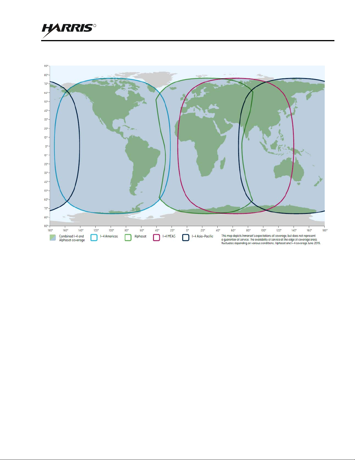
BGAN operates with the INMARSAT 4 satellite constellation of four orbital satellites. See Figure 1-3. The map
shows the global coverage provided by the BGAN satellites. This BGAN system operates in the L-Band spectrum,
with a transmit frequency range of 1626.5 MHz - 1660.5 MHz and a receive frequency range of 1525 - 1559 MHz.
The Alphasat satellite offers additional frequency ranges of 1668 - 1675 MHz and 1518 - 1559 for transmit and
receive, respectively. The INMARSAT 4 constellation provides access worldwide.
Access a BGAN satellite by pointing the BGAN terminal to that satellite. In addition to the satellites, the BGAN
system includes infrastructure equipment on the ground, that connects to telephone networks and the internet. By
accessing the satellites, the BGAN terminal can then connect to telephone and data networks. To make use of BGAN
services, users must insert their GSM/GPRS/UMTS subscriber identity module into the BGAN terminal hardware,
and connect an external telephone handset and/or computer / Personal Data Assistant (PDA) to the BGAN terminal
via a cabled connection.
1-6
Page 24
RF-7800B
R
GENERAL INFORMATION
CL-0365-4200-0003
Figure 1-3. BGAN Worldwide Coverage
1.8 COMPATIBILITY
Successful communications depends on using compatible radios and terminal equipment (computer with web
interface).
1.8.1 BGAN Compatible Radios
The following radios with embedded BGAN terminal remote control capability are compatible with the BGAN
terminal:
• AN/PRC-117G(V)1(C)
• RF-7800M-MP
The BGAN terminal IP data is encrypted by the Sierra II™ Type-1 algorithms in the AN/PRC-117G or the
Acropolis™ II Advanced Encryption Service (AES) encryption algorithms in the RF-7800M-MP. The embedded
software of the manpack radio provides the ability to fully configure, remotely control and provide status and fault
monitoring of the BGAN terminal using the radio’s front panel.
1-7
Page 25

RF-7800B
R
GENERAL INFORMATION
When linked to Harris Falcon III manpack radios or SecNet 54 encryption modules, RF-7800B BGAN terminals
provide end-to-end Type-1 High Assurance Internet Protocol Encryptors (HAIPE)-certified security (AN/PRC117G) or AES256 (RF-7800M-MP) for data transmissions over long-range commercial networks.
1.8.2 Compatible Encryption Equipment
Encryption equipment compatible with the BGAN terminals includes:
• HAIPE Compatible Equipment: AN/PRC117G, Secnet54, or any existing HAIPE (e.g., KG-250,
TACLA NE K G-1 7 5)
• AES256 Encryption Compatible Equipment: RF-7800M-MP, Cisco Router Family
• Software Encryption Compatibility: Compatible VPNs: Cisco-VPN, Client V1 or V2.6.3; Nortel-Contivity
VPN Client, V04-15.06; Netscreen-Remote Client 8.1; Checkpoint-V4.1; and SonicWall
1.8.3 Computer Requirements for Embedded Web Interface
These are the minimum computer system requirements for successfully using the web interface with the BGAN
terminal:
• Web Interface: recent version of Microsoft Internet Explorer (6.0 or greater for example); or Firefox (1.3 or
greater for example) with Java enabled (a portion of the Web interface contains a Java Applet for BGAN
network signal strength indication)
• Computer support for at least one of these interface connections - Ethernet or USB
1.9 OPTIONAL ACCESSORIES
The following are optional accessories:
• 12043-0830-A006 AN/PRC-117G, RF-7800M-MP Black Ethernet Cable, 6 feet
12043-0830-A015 AN/PRC-117G, RF-7800M-MP Black Ethernet Cable, 15 feet
• 12043-0831-A006 AN/PRC-117G, RF-7800M-MP Black Ethernet & ISDN Cable, 6 feet
12043-0831-A015 AN/PRC-117G, RF-7800M-MP Black Ethernet & ISDN Cable, 15 feet
• 12043-0832-A010 Standalone Ethernet, ISDN, USB Cable, 10 feet
• 12043-0833-A010 BGAN, Ethernet Cable, 10 feet
• 12043-0834-A010 Standalone Ethernet & ISDN Cable, 10 feet
• 12043-0835-A010 Standalone ISDN Cable, 10 feet
• 12043-0836-A010 Standalone USB & ISDN Cable, 10 feet
• 12043-0837-A015 Data Extension Cable, Ethernet & ISDN, 15 feet
12043-0837-A025 Data Extension Cable, Ethernet & ISDN, 25 feet
12043-0837-A050 Data Extension Cable, Ethernet & ISDN, 50 feet
• 12043-0839-A010 AN/PRC117G / RF-7800M-MP Radio to RJ45 Ethernet Cable
• 12043-0843-A015
• 12043-0890-A010 BGAN DC Power to 4 Leads / RF-7800B-VU Remote On/Off, 10 feet
12043-0890-A015 BGAN DC Power to 4 Leads / RF-7800B-VU Remote On/Off, 15 feet
1-8
Page 26

GENERAL INFORMATION
R
• 12043-0891-A006 AC/DC Power Supply Cable (RF-505X PS), 6 feet
12043-0891-A015 AC/DC Power Supply Cable (RF-505X PS), 15 feet
• 12043-0892-A006 RF-505X PS / RF-7800B-VU Remote On/Off, 6 feet
12043-0892-A015 RF-505X PS / RF-7800B-VU Remote On/Off, 15 feet
• 12043-0893-A1
• 12094-0894-A1
• 12043-0895-A015 Power Extension Cable, 15 feet
12043-0895-A025 Power Extension Cable, 25 feet
12043-0895-A050 Power Extension Cable, 50 feet
• 12043-0896-A010 BGAN DC Power to 2 Leads, 10 feet
12043-0896-A015 BGAN DC Power to 2 Leads, 15 feet
• 12091-4160-01 ISDN to POTS Converter (ISDN 2-4 wire terminal adapter).
This adapter is used to connect any two existing analog devices (phone and fax
for example) to an ISDN line. In addition, the adapter runs from power provided
over the ISDN line.
RF-7800B
1.9.1 RF-7800B-DU024 Options
The following are optional accessories for the RF-7800B-DU024:
• 12091-0060-01 AN/PRC-117G, RF-7800M-MP Land Portable Ancillary Kit (Battery)
Includes: 12043-0830-A006, 12043-0850-A006, 12091-4010-01
• 12091-4010-01 BGAN Battery Box Kit, Tan (See Figure 3-16)
• 12043-0850-A006 Battery Box Cable, 6 feet
• 12091-4150-01 Fix Mount Kit - for building or other fixed infrastructure (See Figure 2-10)
1.9.2 RF-7800B-VU104 Options
The following are optional accessories for the RF-7800B-VU104:
• 12091-0070-01 AN/PRC-117G, RF-7800M-MP Land Mobile Ancillary Kit
Includes: 12043-0830-A015, 12043-0840-A015, F03-0008-906 Fuse Holder,
F15-0012-003 Fuse, Automotive Blade, 5 A 32 V
• 12091-4200-01 HF/VHF/UHF CoSite Low Pass Filter Kit for L-Band
Filter is for colocated HF/VHF/UHF radio power amplifier output of up to 200 W,
removing HF/VHF/UHF harmonics which may impact BGAN terminal operational
performance
• 12091-5112-01 Mast Assembly, 4 foot, Heavy
12091-5113-01 Mast Assembly, 6 foot, Heavy
12091-5117-01 Mast Assembly, 2 foot, Light (See Figure 2-9)
• 12091-4170-01 Pot Magnet Assembly
1-9
Page 27

RF-7800B
R
GENERAL INFORMATION
This page intentionally left blank.
1-10
Page 28
RF-7800B
R
NOTE
12 VDC CABLE ASSEMBLY
(12043-0843-A015)
BGAN - ETHERNET
CABLE ASSEMBLY
(12043-0833-A010)
SYSTEM SETUP AND TEARDOWN
CHAPTER 2
SYSTEM SETUP AND TEARDOWN
2.1 ITEMS INCLUDED WITH RF-7800B BGAN TERMINAL
The standard items included with the Broadband Global Area Network (BGAN) terminals are described below.
Refer to Paragraph 1.9 for optional accessories.
RF-7800B-VU104 Land Mobile BGAN Terminal includes the following. See Figure 2-1.
• 12043-0833-A010 BGAN to Ethernet Cable, 10 feet
• 12043-0843-A015 Automobile 12 VDC Power Cable, 15 feet
• 12091-0040-12 BGAN Terminal, Class 10 Land Mobile, Tan
RF-7800B-DU024 Land Portable BGAN Terminal includes the following. See Figure 2-2.
• 12043-0833-A010 BGAN to Ethernet Cable, 10 feet
• 12043-0894-A1 AC to DC Power Supply (includes international plug adapter kit). Refer to Paragraph 2.5.3.
• 12091-0020-12 BGAN Terminal, Class 2 Land Portable, Tan
For BGAN network access, contact your service provider for
a Universal Mobile Telecommunications System (UMTS)
Subscriber Identification Module (SIM) (USIM) and its
Personal Identification Number (PIN), and Satellite Terminal
configuration instructions.
LAND MOBILE
BGAN TERMINAL
(12091-0040-12)
BGAN - DC POWER TO VEHICLE
CL-0365-4200-0004
Figure 2-1. Items Included with RF-7800B-VU104
2-1
Page 29
RF-7800B
R
WARNING
WARNING
BGAN - AC TO DC POWER
SUPPLY ASSEMBLY
(12043-0894-A1)
ADAPTERS
NOT SHOWN
CABLE ASSEMBLY
BGAN TERMINAL
(12091-0020-12)
SYSTEM SETUP AND TEARDOWN
LAND PORTABLE
BGAN - ETHERNET
(12043-0833-A010)
CL-0365-4200-0005
Figure 2-2. Items Included with RF-7800B-DU024
2.2 INSTALLATION GUIDELINES
The information contained here provides general guidelines for installing the BGAN terminal. Read this chapter in
its entirety before beginning installation.
2.2.1 Environmental
The BGAN terminal will perform in the environment specified in Table 1-1.
Do not operate the BGAN terminal during electrical storms.
Disconnect the terminal from the computer and radio and store
the unit indoors if lightening is anticipated in the area of
operation. Electrocution may result in severe personal injury
or death.
Never use the BGAN terminal where blasting work is in
progress. Observe all restrictions and follow any regulations
or rules. Do not use the terminal while at a fuel filling station,
do not use near fuel or chemicals. areas with potentially
explosive environments are often, but not always, clearly
marked.
2-2
Page 30

RF-7800B
R
CAUTION
SYSTEM SETUP AND TEARDOWN
Avoid placing BGAN terminal near any source of heat such as
an open flame or cigarettes.
2.2.2 Dimension and Weight Information
Refer to Table 1-1 for the dimensions and weights.
2.2.3 Power Requirements
Refer to Table 1-1 for power requirements. Refer to Paragraph 1.9 for the various optional power cables available.
2.2.4 Grounding
Neither the RF-7800B-VU104 or RF-7800B-DU024 require mounting on a ground plane for performance.
2.3 UNPACKING AND REPACKING
Equipment is packed in corrugated boxes. A two-piece foam enclosure protects the equipment against corrosion and
rough handling. Boxes and packing materials should be retained in case the equipment is reshipped.
2.3.1 Unpacking
Perform the following procedure to unpack the BGAN terminal:
a. Inspect the exterior of the box for signs of damage during shipment. Document any problems and report
them to the proper authority.
b. Move the boxed equipment to the general location where it is to be installed.
c. After removing the equipment, check the contents against the packing slip to see that the shipment is
complete. Report discrepancies to Harris Product Service Department
(telephone: 585-244-5830, toll free: 866-264-8040, web: https://tcpremier.harris.com/).
2.3.2 Repacking
Perform the following procedure to repack the BGAN terminal:
a. Use the original box, if it was retained. If not, use a box that allows at least three inches of clearance on
all sides of the BGAN terminal components.
b. Use the original packing material, if it was retained. If not, use foam packing material to fill the space
between the BGAN terminal components and the box. Surround the entire unit with several inches of
foam packing material.
c. Use a good quality packing tape (or straps) to seal the box after closing.
2.4 BGAN TERMINAL SETUP
After receiving the USIM card from your BGAN service provider, install the card into the BGAN terminal.
2-3
Page 31

RF-7800B
R
NOTE
CAUTION
HOLDER
SYSTEM SETUP AND TEARDOWN
2.4.1 Installing USIM in RF-7800B-DU024
Perform the following procedure to install the USIM/SIM in RF-7800B-DU024:
a. Position the BGAN terminal so that the bottom surface is facing you.
b. Remove the four screws and the USIM plate to access the USIM card holder. See Figure 2-3.
c. Put your index finger on the USIM holder and rotate counterclockwise to open. See Figure 2-4.
d. Lift the USIM card holder up in order to place the USIM card in the holder. See Figure 2-5.
Do not bend or damage the USIM/SIM. Damaged contacts
may cause the card not to work.
USIM cards are sensitive to electrostatic discharges.
e. Install the USIM card in the card holder making sure the gold contacts are facing down. The angled part
of the USIM is in the upper right-hand corner. See Figure 2-5.
f. With the card in place, push the holder down and with your index finger, rotate the locking mechanism
clockwise to lock card in place. See Figure 2-6.
g. Put the USIM plate back on and tighten the four screws. See Figure 2-3.
USIM CARD
CL-0365-4200-0006
Figure 2-3. Accessing the USIM Card Holder on RF-7800B-DU024
2-4
Page 32

SYSTEM SETUP AND TEARDOWN
R
ANGLED EDGE
GOLD CONTACTS
ON THIS SIDE
UNLOCKED POSITION
CL-0365-4200-0007
Figure 2-4. Opening the USIM Card Holder on RF-7800B-DU024
RF-7800B
OF USIM CARD
CL-0365-4200-0008
Figure 2-5. Placing the USIM Card in Holder on RF-7800B-DU024
LOCKED POSITION
CL-0365-4200-0009
Figure 2-6. USIM Card Located in Holder on RF-7800B-DU024
2-5
Page 33

RF-7800B
R
NOTE
CAUTION
SYSTEM SETUP AND TEARDOWN
2.4.2 Installing USIM in RF-7800B-VU104
Perform the following procedure to install the USIM/SIM in the RF-7800B-VU104:
a. Position the BGAN terminal with the topside down onto a smooth/soft surface to prevent scratching the
radome and with the bottom surface facing you.
b. Remove the four screws and the USIM plate to access the USIM card holder. See Figure 2-7.
c. Put your index finger on the USIM holder and rotate counterclockwise to open.
d. Lift the USIM card holder up in order to place the USIM card in the holder. See Figure 2-8.
Do not bend or damage the USIM/SIM. Damaged contacts
may cause the card not to work.
USIM cards are sensitive to electrostatic discharges.
e. Install the USIM card in the card holder making sure the gold contacts are facing down. The angled part
of the USIM is in the upper right-hand corner. See Figure 2-8.
f. With the card in place, push the holder down and with your index finger, rotate the locking mechanism
clockwise to lock card in place.
g. Put the USIM plate back on and tighten the four screws. See Figure 2-7.
2-6
Page 34

RF-7800B
R
USIM CARD
HOLDER
ON THIS SIDE
SYSTEM SETUP AND TEARDOWN
DRAIN HOLE
(4 PLACES)
CL-0365-4200-0010
Figure 2-7. Accessing the USIM Card Holder and Drain Holes on RF-7800B-VU104
GOLD CONTACTS
ANGLED EDGE
OF USIM CARD
CL-0365-4200-0012
Figure 2-8. Placing the USIM Card in Holder on RF-7800B-VU104
2-7
Page 35

RF-7800B
R
SYSTEM SETUP AND TEARDOWN
2.5 INSTALLATION PROCEDURES
The paragraphs that follow describe the installation of an BGAN terminal.
2.5.1 RF-7800B-VU104 Installation
RF-7800B-VU104 is intended for installation onto a vehicle roof. Some installation hardware may need to be
installer furnished. Tools and installation materials will vary for each application.
a. The four drain holes on the bottom of the RF-7800B-VU104 are shipped in the open position. See
Figure 2-7. This allows any moisture from condensation to drain out. If the operational conditions
require that these be closed, periodic maintenance to open these and drain any moisture will be required.
Refer to Paragraph 5.1.
b. If using a magnetic mount, place BGAN terminal on roof of vehicle. Make sure the area is clear before
mounting the antenna using the magnetic mounts. If the mounting area is dirty or covered with snow or
ice, the strength of the magnetic mounts may be compromised.
c. If mounting the BGAN terminal on a flat surface using 0.213 - 0.312 inch bolts with 5/16-inch hole
stainless steel flat washers, and 5/6-inch nut, do the following:
1. Make hole pattern template from RF-7800B-VU104 mounting holes.
2. Place template on flat mounting surface and drill holes.
3. Mount RF-7800B-VU104 using 0.213 - 0.312 inch bolts with 5/16-inch hole stainless steel flat
washers, and 5/6-inch nut.
d. If mounting the BGAN terminal using a pole mount mast assembly, do the following:
1. Mount the base of the pole mount on a standard 4-bolt antenna base which can support up to 50
pounds (22.68 kg). See Figure 2-9.
2. Mount the BGAN terminal to the pole mount mast.
e. Make data and power connections. Refer to Paragraph 2.5.3.
2-8
Page 36

R
DETAIL
(4 PLACES)
SEE DETAIL
RF-7800B
SYSTEM SETUP AND TEARDOWN
CL-0365-4200-0011
Figure 2-9. Pole Mount Option
2.5.2 RF-7800B-DU024 Fixed/Semi-fixed Installation
The Land Portable BGAN Terminal can be mounted on a pole or flat surface (such as a wall or roof) using the Fixed
Mount Kit, 12091-4150-01. See Figure 2-10. This kit includes a universal pole mount, incline bracket, bubble level
indicator and holder, pole ground cable, and four terminal mounting screws. Items required to mount the universal
pole mount to a structure are customer furnished. Proper installation ensures that the BGAN terminal is always
correctly pointed at the satellite. The BGAN terminal can then be left alone for an extended period of time without
having to be re-pointed or set-up. The fixed mount kit accessory can be re-used to install the BGAN terminal in
different locations.
When mounted in a location where access to the BGAN terminal may not be straightforward (for example, mounted
high on a wall), set the BGAN terminal to recover automatically after a power outage. To permit this fixed
installation, modify the following BGAN terminal property using the embedded Web interface. See Figure 4-4.
• Bypass Antenna Pointing and Auto Register is enabled
The following items are found in the Fixed Mount Kit, 12091-4150-01. Mount to a suitable surface.
• Fixed Mount Screws
• Mounting bracket and shaft
• Level
• Grounding strap
2-9
Page 37

RF-7800B
R
NOTE
MOUNT
AND HOLDER
SCREW, CAP,
HEX SOCKET,
1/4 - 20X1/2
(4 PLACES)
NOTE: USE CUSTOMER FURNISHED
MOUNTING HARDWARE FOR POLE
OR SURFACE MOUNT.
BRACKET ASSEMBLY
SYSTEM SETUP AND TEARDOWN
AZIMUTH CANISTER/INCLINE
BUBBLE LEVEL INDICATOR
UNIVERSAL
CL-0365-4200-0013
Figure 2-10. Fixed Mount Option
2.5.3 Cable Connections
For connector pinouts, refer to Paragraph A.1. See Figure 2-11 for some installation options. Refer to Paragraph 3.3
for detailed connection information. In general, install the following:
• Data cable between BGAN terminal and computer
• Power cable between BGAN terminal and power source. For the RF-7800B-DU024 using the BGAN, AC
to DC Power Supply Assembly with plug kit, use one of the following plugs:
• ST-5: United States, Canada, Japan, China, Taiwan
• ST-7: United Kingdom, Hong Kong, Singapore
• ST-9: Germany, France, Indonesia, Korea
• ST-16: Australia, New Zealand, China
• ST-9C: European Union, United Arab Emirates, South America
Do not use excessive force when connecting the data and
power cables to the BGAN terminal. Connectors are keyed.
2-10
Page 38

SYSTEM SETUP AND TEARDOWN
R
POWER CABLE,
12043-0843-A015
AC TO DC POWER
12043-0894-A1
BGAN TO RADIO
ETHERNET CABLE,
12043-0830-A006
RADIO RED
ETHERNET CABLE,
12043-0760-A006
CABLE,
USB AND
ISDN CABLE,
(OPTION)
NOTE: LAND MOBILE TERMINAL
SHOWN. LAND PORTABLE MAY
ALSO BE USED.
BGAN ETHERNET
12043-0833-A010
RF-7800B
SUPPLY ASSEMBLY,
2.5.4 Protecting Connectors
If connectors are to be exposed to a wet or humid environment for extended periods of time, protect the exposed
connectors as follows:
a. Silicone Grease (Dow Corning DC-5 or Similar Corrosion Preventative Compound)
Coat all ground connections with silicone grease or an equivalent dielectric compound. Apply a coating
approximately 1/8-inch (0.32 cm.) thick. This coating will prevent deterioration of the antenna
connection and its associated hardware. This will also protect the insulator from conductive
contaminants that could degrade the insulating properties of the connector system, such as oil, dirt, dust,
and corrosive material from the atmosphere. This is especially important in a salt-laden air environment.
b. Electrical Tape (3M Company 33+, Permacel 29R or similar)
AUTOMOBILE 12 VDC
Figure 2-11. Cabling Options
OR
12043-0836-A010
CL-0365-4200-0014
Wrap connectors exposed to weather with several layers of weather-resistant electrical tape or similar
product (3M Company 33+, Permacel 29R). Wrap the tape as close as possible to the case, and far
enough up the cable to prevent moisture from contacting any part of the connector.
2-11
Page 39

RF-7800B
R
SYSTEM SETUP AND TEARDOWN
2.6 INITIAL TURN-ON / CHECK
Once the system is installed, verify that the BGAN terminal is operational. Perform the following:
a. Make sure the data cable is connected to BGAN terminal and computer.
b. Make sure the power cable is connected to BGAN terminal and power source.
c. Turn on power to BGAN Terminal and wait at least 30 seconds for the BGAN Terminal to power-up.
d. Set up a Microsoft Windows computer with the ability to automatically receive an IP address.
1. Select Start > Settings > Networks and Connections.
2. Select Local Area Connection and select Properties from the context menu.
3. Select the Transmission Control Protocol/Internet Protocol (TCP/IP) connection and select the
Properties button.
4. Select Obtain an IP address automatically from the General tab of the TCP/IP Properties page.
5. Select OK to close the TCP/IP Properties page and OK again to close the Local Area Connection
Properties page.
e. Use a web browser on the computer to access the BGAN terminal Web interface using its Internet
Protocol (IP) address. For example, open Internet Explorer and enter into the Address field the default
Web interface address for the BGAN terminal: http://192.168.128.100. If the web interface does not
appear, refer to Paragraph 2.6.1 to determine the correct Ethernet IP address of the BGAN terminal, and
use that value in the browser address field. Verify that the internet browser’s Temporary Internet Files
Settings are set to check for newer versions of stored pages “Every time I visit the webpage” to ensure
that updated status can be viewed properly.
2.6.1 Determining Ethernet IP address of BGAN Terminal
The BGAN Terminal's default Ethernet IP address can be modified from the Web Interface, requiring a change to
the address provided above. Connect the BGAN Terminal to a Microsoft Windows computer and determine its
Ethernet IP address.
a. Open a Command prompt window (select Start > Run, and type cmd and press Enter).
b. Type ipconfig in the Command Prompt window. The value of the Default Gateway will be the value
to place in the browser Address field. Refer to Tabl e 5-4 (Was the embedded DHCP server turned off?)
if the computer does not obtain an IP address from the BGAN Terminal.
2-12
Page 40

RF-7800B
R
DATA DC POWER
OPERATION
CHAPTER 3
OPERATION
3.1 INTRODUCTION
The Broadband Global Area Network (BGAN) terminal contains an integrated Global Positioning System (GPS)
receiver that is used to provide location information to the BGAN system. GPS location information is required to
register with the BGAN system, and the BGAN terminal automatically tries to get a GPS position fix every time it
is powered up.
The GPS antenna is located in the main antenna. For optimum GPS signal reception, make sure the BGAN terminal
is placed in a horizontal position pointed towards the sky. Since the GPS receiver needs to see at least three satellites,
it should have visibility of a large part of the sky without obstructions from buildings, mountains or trees. So it might
be necessary to take the BGAN terminal out to a clear space to obtain a new GPS location. It may be possible to
obtain a new GPS location in a less favorable circumstance, but the time to get the fix may be longer.
3.2 OPERATIONS TASK SUMMARY
Perform the following task to begin using the BGAN terminal that has been setup with a Subscriber Identity Module
(SIM) card.
• Make cable connections
• Position the Land Portable BGAN Terminal (RF-7800B-DU024)
• Turn on the BGAN terminal and use pointing tones to locate satellite
• Verify connection to the BGAN network
RF-7800B-VU104 has no controls or indicators.
RF-7800B-DU024 has a power switch on the side. Refer to Paragraph 3.5. Switch positions are: OFF, ON, and ON
with audio pointing tones. ON with audio pointing tones is used to accurately point the terminal toward the satellite
for optimal data throughput.
3.3 MAKE CABLE CONNECTIONS
Connectors for RF-7800B-VU104 are shown in Figure 3-1. Connectors for RF-7800B-DU024 are shown in
Figure 3-2. Connect the power and data cables to the BGAN terminal. Engage the connector locking mechanism to
secure the cable to the BGAN terminal.
CL-0365-4200-0015
Figure 3-1. RF-7800B-VU104 Connectors
3-1
Page 41

RF-7800B
R
DATA
CONNECTOR
OPERATION
POWER
CL-0365-4200-0016
Figure 3-2. RF-7800B-DU024 Connectors
3.3.1 Data Connections
Make a data connection to a computer, radio, an Internet Protocol (IP) encryption device, or an ISDN device. The
Data Extension Cable for Ethernet & ISDN, 12043-0837-A0xx, can be used to extend the terminal data connection
out 15, 25, or 50 feet (4.57, 7.62, or 15.24 meters).
• Ethernet
• Universal Serial Bus (USB)
• Integrated Services Digital Network (ISDN)
3.3.1.1 Connect Data by Ethernet
Connect the BGAN terminal to the computer Ethernet port using an Ethernet cable supplied with the BGAN terminal
or another Ethernet cable option.
• See Figure 3-3 for BGAN Ethernet Cable, 12043-0833-A010 (supplied with BGAN terminal).
• Standalone Ethernet, ISDN, USB Cable, 12043-0832-A010 (optional).
• See Figure 3-4 for Standalone Ethernet and ISDN Cable, 12043-0834-A010 (optional).
RF-7800B DATA
ETHERNET
CONNECTOR
CL-0365-4200-0017
Figure 3-3. BGAN Ethernet Cable, 12043-0833-A010
3-2
Page 42

R
Figure 3-4. Standalone Ethernet and ISDN Cable, 12043-0834-A010 (Optional)
ETHERNET
CONNECTOR
USB
CONNECTOR
ISDN
CONNECTOR
3.3.1.2 Connect Data by USB
RF-7800B
OPERATION
ISDN
CONNECTOR
CONNECTOR
CL-0365-4200-0019
Connect the BGAN terminal to the computer USB port using a USB cable option. Use Standalone Ethernet, ISDN,
USB Cable, 12043-0832-A010, or Standalone USB and ISDN Cable, 12043-0836-A010 (see Figure 3-5). On first
use of the USB port, the computer will detect that new USB hardware has been connected. Follow the installation
instructions for the USB Local Area Network (LAN) LINK driver software.
RF-7800B DATA
CL-0365-4200-0020
Figure 3-5. Standalone USB and ISDN Cable, 12043-0836-A010 (Optional)
3-3
Page 43

RF-7800B
R
CONNECTOR
CONNECTOR
BLACK ETHERNET
CONNECTOR
RF-7800B DATA
CONNECTOR
RADIO
BLACK ETHERNET
CONNECTOR
RF-7800B DATA
CONNECTOR
OPERATION
3.3.1.3 Connect Data by ISDN
Connect the BGAN terminal to the computer or phone ISDN port using an ISDN cable option.
• Standalone Ethernet, ISDN, USB Cable, 12043-0832-A010.
• See Figure 3-4 for Standalone Ethernet and ISDN Cable, 12043-0834-A010.
• See Figure 3-5 for Standalone USB and ISDN Cable, 12043-0836-A010.
• See Figure 3-6 for Standalone ISDN Cable, 12043-0835-A010.
RF-7800B DATA
ISDN
CL-0365-4200-0021
Figure 3-6. Standalone ISDN Cable, 12043-0835-A010 (Optional)
3.3.1.4 Connect Data to Radio
Connect the BGAN terminal to a radio using cable option.
• See Figure 3-7 for BGAN to Radio Black Ethernet Cable, 12043-0830-A0xx (optional).
• See Figure 3-8 for BGAN to Radio Black Ethernet and ISDN Cable, 12043-0831-A0xx (optional).
RADIO
CL-0365-4200-0022
Figure 3-7. BGAN to Radio Black Ethernet Cable, 12043-0830-A006 (Optional)
Figure 3-8. BGAN to Radio Black Ethernet and ISDN Cable, 12043-0831-A006 (Optional)
3-4
ISDN
CONNECTOR
CL-0365-4200-0023
Page 44

RF-7800B
R
ADAPTERS
NOT SHOWN
GROUND (BLACK WIRE)
CL-0365-4200-0028
OPERATION
3.3.2 Power Connections
Connect the BGAN terminal to a power source as described in this section. Each of these power connection options
can be extended using the BGAN DC Power Extension, 12043-0895-A015, -A025, or -A050 (includes activation).
For power sources which do not have built-in current limiting (< 100 W) or fuses, procure the F03-0008-906 Fuse
Holder along with the F15-0012-003 Automotive Fuses (Automotive Blade, 5 A 32 V) for applications for 12 V
applications. For 24 V applications, use F15-0012-001 for 3 A fusing.
3.3.2.1 Connect BGAN Terminal Power to Commercial Vehicle 12 VDC
Connect BGAN terminal to a vehicle using 12043-0843-A015 Cable Assembly, BGAN, DC Power to Vehicle 12
VDC. See Figure 3-9.
CL-0365-4200-0026
Figure 3-9. BGAN, DC Power to Vehicle 12 VDC, 12043-0843-A015
3.3.2.2 Connect BGAN Terminal Power to AC to DC Power Supply
Connect BGAN terminal to a power supply using 12043-0894-A1 Power Supply Assembly, BGAN, AC to DC. See
Figure 3-10. Plug kit (not shown) includes five black plugs. Refer to Paragraph 2.5.3.
CL-0365-4200-0027A
Figure 3-10. BGAN, AC to DC Power Supply Assembly, 12043-0894-A1
3.3.2.3 Connect BGAN Terminal Power to Battery
Connect BGAN terminal to a battery using 12043-0896-A010, or -A015 Cable Assembly, BGAN DC Power to 2
Leads. See Figure 3-11.
+DC (RED WIRE)
Figure 3-11. Cable Assembly, BGAN DC Power to 2 Leads, 12043-0896-A0xx
3-5
Page 45

RF-7800B
R
GROUND (BROWN)
ACTIVATION (ORANGE)
GROUND (BROWN)
OPERATION
Optionally, for RF-7800B-VU104, use the 12043-0890-A010, or -A015 Cable Assembly, BGAN DC Power to 4
Leads as follows: red (+DC), black (ground), orange (power control signal), brown (ground). See Figure 3-12. The
Power Control Signal allows the BGAN terminal to be remotely powered on/off. Connecting the power control
signal to ground will turn the power on to the BGAN terminal.
+DC (RED)
GROUND (BLACK)
ACTIVATION (ORANGE)
CL-0365-4200-0029
Figure 3-12. Cable Assembly, BGAN DC Power to 4 Leads, 12043-0890-A0xx
3.3.2.4 Connect BGAN Terminal Power to 26 VDC Power Supply
Connect BGAN terminal to a 26 VDC power supply (RF-505X-PS) using 12043-0891-A006, or -A015 BGAN DC
Power to 26 VDC. Connect power to RF-505X-PS J15 or J16. See Figure 3-13.
CL-0365-4200-0030
Figure 3-13. AC/DC Power Supply Cable (RF-505X-PS), 12043-0891-A0xx
Optionally, for RF-7800B-VU104, use the 12043-0892-A006, or -A015 Cable Assembly, BGAN DC Power to 26
VDC with remote On-Off as follows: P2 (26 VDC Power Supply), orange (power control signal), brown (ground).
This can also be used with the 12043-0845 Power Extension Cable (extension cable plugs into BGAN power). See
Figure 3-14. The power control signal allows the BGAN terminal to be remotely powered on/off. Connecting the
power control signal to ground will turn the power on to the BGAN terminal.
CL-0365-4200-0031
Figure 3-14. BGAN DC Power to 26 VDC/Remote On/Off, 12043-0892-A0xx
3-6
Page 46

RF-7800B
R
BATTERY CABLE
CONNECTOR
OPERATION
3.3.2.5 Connect RF-7800B-DU024 Power to BGAN Battery Box Kit
Connect RF-7800B-DU024 to BGAN Battery Box Kit, 12091-4010-01, using 12043-0850-A006 BGAN DC Power
to Battery Box cable. See Figure 3-15. Refer to Paragraph 5.3 for information on batteries. See Figure 3-16 for
Battery Box.
CL-0365-4200-0032
Figure 3-15. BGAN DC Power to Battery Box Cable, 12043-0850-A006
CL-0365-4200-0037
Figure 3-16. Battery Box Kit, 12091-4010-01
3-7
Page 47

RF-7800B
R
LIFT HERE
OPERATION
3.4 USING RF-7800B-DU024 TERMINAL STAND
The Land Portable BGAN terminal stand is used to position the terminal in the correct direction.
a. Place the Satellite terminal face down on a flat surface to open up the stand. See Figure 3-17.
b. Open the stand by placing your index finger in the upper right (or upper left) hand corner of the unit and
placing your other hand on the side of the unit and pulling upwards.
c. Slide out the front stabilizer. See Figure 3-18.
d. Set the Terminal back on a flat surface for pointing.
e. Make adjustments as necessary. Normally there is no need to tighten the stand using the two screws
located underneath the stand. If the stand no longer can stand at the angle required for best pointing
elevation, tighten the stand using the two screws located underneath the stand. See Figure 3-18.
LIFT HERE
CL-0365-4200-0033
Figure 3-17. Open RF-7800B-DU024 Terminal Stand
3-8
Page 48

RF-7800B
R
CAUTION
CARRY
OPERATION
HANDLE
SET KNOBS
CL-0365-4200-0034
Figure 3-18. Slide Out Stabilizer
3.5 RF-7800B-DU024 INITIAL SETTINGS AND TURN-ON
Perform the following to point RF-7800B-DU024 Land Portable BGAN terminal and get a GPS fix.
Do not stand in front of the BGAN terminal. The BGAN
terminal emits radio frequency energy when in operation. Do
not stand or place objects in front of the antenna when the
BGAN terminal is operational. Maintain a distance of two
meters or more from the front of the antenna.
a. Take the Land Portable BGAN Terminal outside and lay it down flat. Verify that the unit has an open
view of the sky to get a GPS fix.
b. Power up the BGAN terminal by rotating the ON/OFF knob to either ON or ON with audio. To get a
GPS fix only (without using pointing tones), use ON. See Figure 3-19. Typically, a GPS 3D fix can be
successfully attained in less than 90 seconds.
c. If using audio, point the terminal in the general direction of a satellite to get a beeping tone. Point the
BGAN terminal towards the equator, pointed South if in the Northern Hemisphere, and pointed North
if in the Southern Hemisphere. As the terminal is aimed more directly at the satellite, the tones will
increase in frequency.
d. Connect the BGAN terminal to a computer and power source.
3-9
Page 49

RF-7800B
R
NOTE
OPERATION
e. Access the Web interface.
1. Open a web browser and type in the Ethernet IP address of the BGAN terminal (default is
http://192.168.128.100). Refer to Paragraph 2.6 Initial Turn-On / Check for detailed instructions.
The web interface opens up to the Properties page. See Figure 4-6.
2. Monitor the Web interface PROPERTIES page GPS Position information to determine when a
GPS Fix is obtained. Refer to Paragraph 3.7.1.
The BGAN terminal will not achieve optimal capabilities if
there is excessive RF interference on its operational or
adjacent channels. For maximum performance, a clear Line of
Sight (LOS) path should exist to satellites.
CL-0365-4200-0035
Figure 3-19. RF-7800B-DU024 ON, OFF, or ON with Audio Switch
3.6 RF-7800B-VU104 INITIAL SETTINGS AND TURN-ON
Perform the following to point RF-7800B-VU104 Land Mobile BGAN Terminal and get a GPS fix.
a. Move the vehicle with Land Mobile BGAN Terminal outside. Verify that the unit has an open view of
the sky to get a GPS fix.
b. Connect the BGAN terminal to a computer and power source.
c. Power up the BGAN terminal.
After power is applied, RF-7800B-VU104 begins a start-up sequence. The tracking antenna searches
for BGAN satellites and the antenna motors may be heard during this time. After locking onto a BGAN
satellite, some minor adjustments are made to acquire optimum signal strength. Eventually, an optimum
position is reached.
d. Access the Web interface.
1. Open a web browser and type in the Ethernet IP address of the BGAN terminal (default is
http://192.168.128.100). Refer to Paragraph 2.6 Initial Turn-On / Check for detailed instructions.
The web interface opens up to the Properties page. See Figure 4-6.
3-10
Page 50

RF-7800B
R
OPERATION
2. Monitor the Web interface PROPERTIES page GPS Position information to determine when a
GPS Fix is obtained. Typically, a GPS 3D fix can be successfully attained in less than 90 seconds.
Refer to Paragraph 3.7.1.
Automatic tracking keeps the antenna pointed towards the satellite once the vehicle starts moving. During short
outages (while driving under a bridge, for example), the antenna will remain in the same position and will pick up
the satellite signal immediately upon exiting the blockage. For longer outages, the antenna may need to repeat the
search pattern to reacquire the satellite signal.
Circuit switched and packet switched connections will recover from signal outages, as the antenna will perform a
360 degree rescan every 15-20 seconds. In this case, the BGAN terminal will still remain Registered on the network.
For outages longer than 60 minutes, the BGAN terminal will need to re-register prior to activating additional circuit
or packet switched connections. Refer to Paragraph 4.4.3 to reactivate a connection.
3.7 BGAN SERVICES
BGAN requires GPS for registration with the BGAN network, for both circuit and packet switched connections. For
emergency circuit switched voice connections, GPS is not required. Both the RF-7800B-DU024 and the RF-7800BVU104 BGAN terminals contain an embedded GPS receiver. The BGAN terminal keeps a record of its last GPS fix
acquired between power cycles. If the BGAN terminal has not moved far since it last acquired a GPS fix (i.e.,
remained in the same spot beam), then it can register from the stored GPS position. If the BGAN Terminal attempts
to register before it acquires a new GPS fix, it will attempt to register and connect based on the stored GPS fix. If
the stored GPS fix does not allow it to connect successfully, the BGAN terminal will wait for a new GPS fix and
then complete the registration and connection.
3.7.1 Obtaining a GPS Fix
In normal operation, a GPS receiver needs to be able to receive signals from at least four satellites so that it can then
calculate a latitude, a longitude and an altitude. This position fix is referred to as a 3-dimensional or 3-D fix. If only
three GPS satellites can be seen by the GPS receiver, then the last available altitude measurement is assumed and
the GPS receiver calculates a position fix based on latitude and longitude only. This simpler position fix is referred
to as a 2-dimensional or 2-D fix and is quicker and easier to obtain than a 3-D fix, but may be less accurate.
The embedded GPS receiver, with a clear view of the sky, normally takes between 60 and 90 seconds to attain a 3D GPS fix. How quickly the GPS receiver is able to acquire a fix can also be affected by the visibility that the GPS
receiver has of the GPS satellites. The GPS system is relatively tolerant of atmospheric conditions such as heavy
cloud or rainfall. However, physical blockages, such as tall buildings or terrain can significantly degrade the ability
of the GPS receiver to obtain a fix. For this reason, ensure that the GPS receiver has a clear view of as much open
sky as possible.
3.7.2 GPS and BGAN Registration
The BGAN terminal uses the GPS information to perform both Registration, as well as the creation of packet and
circuit switched voice and data connections. BGAN Terminal Registration is performed in a Regional Beam,
whereas voice and data connections utilize BGAN Spot Beams. The GPS information instructs which Regional
Beam to register on, as well as what spot beam the BGAN terminal will create the voice or data connection on. If a
packet switched connection has been inactive for some time, the BGAN network may remove the connection,
placing the BGAN terminal back in a Registered state. When additional IP data is required to be transferred from
the BGAN terminal to the network, the terminal will automatically recreate the packet switched connection. This
will place the terminal back into a connected state.
3-11
Page 51

RF-7800B
R
OPERATION
For the RF-7800B-VU104, traveling from one spot beam to another, GPS information will be used to allow a
seamless spot beam transition, without the end user even knowing.
Finally, there are Universal Mobile Telecommunications System (UMTS) Subscriber Identification Module (USIM)
cards known as “Discreet SIM cards”, which do not provide GPS location information of the BGAN terminal to the
BGAN Network. These USIM cards will only provide the Regional or Spot Beam Identification (ID) to the network.
Speak to your BGAN Service Provider for provisioning of these types of cards.
3.7.3 ISDN Voice Telephony Services
The Satellite Terminal provides an ISDN interface to connect devices for Circuit Switched voice and data services.
It is a Basic Rate (also known as 2B+D) interface and uses the European ISDN protocol. Service for only one 64
kbps B-channel is provided at a time.
The BGAN terminal has been successfully tested with the following ISDN handsets:
• ASCOM Eurit 33 plus
• SwissVoice Eurit 25
• Nera ISDN handsets (old Fleet and new WorldPro handsets)
• Siemens Gigaset SX255
• ISDN to Plain Old Telephone System (POTS) Converter, 12091-4160-01, using any 2-wire analog handset
Before the handset can accept incoming voice calls, program a Mobile Subscriber Number (MSN) using the same
number as programmed in the terminal (default is 1). Refer to Paragraph 4.4.2. This ensures that incoming voice
calls are directed to the handset. The handset's instruction manual will explain how to do this. Emergency calls can
be made without the correct MSN programmed into the handset.
With an ISDN Handset: Connect the phone to the BGAN terminal using a data cable to ISDN connector. The display
screen will read "Registering… Please Wait" for less than a minute, then the display will read "Normal Mode".
To command the BGAN Terminal to Register: After the phone is in Normal Mode, Press "#1#", then press send,
then press "End Call". The phone is now registered and can make outgoing calls.
3.7.3.1 Dialing
As the ISDN numbering system follows the same pattern as the normal telephone system, dialing is carried out in
exactly the same manner as making a normal telephone call. The subscriber number is used with the same
international and area codes as any other telephone network.
3.7.3.2 Multi-Subscriber Numbering (MSN)
ISDN supports MSN which allows more than one telephone number to be allocated to an ISDN line. The BGAN
Satellite Terminal assigns different MSNs for 4 k Voice, 3.1 kHz Audio, 64 k Unrestricted Digital Information (UDI)
and 56 k Restricted Digital Information (RDI) devices. Each incoming call will be directed to the appropriate MSN
depending on the type of call. This allows proper routing of incoming calls to the correct ISDN device (e.g. ISDN
phone, data card or Fax).
3-12
Page 52

RF-7800B
R
OPERATION
3.7.4 Data Services
The five types of Packet Switched data connections (Network Connections) consist of a Background data service,
and four Quality of Service (QoS) Streaming services.
Background Service: A Background connection shares the bandwidth of the satellite spot beam with all the other
active background connections in the spot beam, minus all the bandwidth allocated to streaming connections.
Background connections can reach up to 492 kbps for the RF-7800B-VU104, and up to 432 kbps for the RF-7800BDU024. For usage such as Email and Internet browsing, usually a Background connection operates at a higher data
rate and less cost than a Streaming connection. Background service rates are charged by the amount of MegaBytes
transferred across the network.
Streaming Service: A Streaming data connection acquires a dedicated amount of bandwidth from the satellite spot
beam to ensure a minimum amount of guaranteed QoS of data throughput for that connection. The Streaming
Service allows the ability for data rates of 32 kbps, 64 kbps, 128 kbps, or 256 kbps. The RF-7800B-VU104 can
operate at Streaming rates of up to 256 kbps, whereas the RF-7800B-DU024 can operate at streaming rates of up to
128 kbps.
Streaming channels may be preferred when transferring video teleconferencing across the network. Streaming
service rates are charged by the amount of minutes the connection is up on the network. Refer to your BGAN Service
Provider for associated costs.
It should be noted, that International Marine/Maritime Satellite (INMARSAT) guarantees the QoS of the stream up
to where their private network meets the public Internet. It is up to the customer to make arrangements to maintain
the QoS over the Internet to the final destination.
Each device connected to the BGAN terminal can have its own primary Network Connection (e.g. background or
streaming connection). Up to 11 devices may be connected to one BGAN terminal at a time. Each device will have
a separate global IP address to the network.
3.7.5 Virtual Private Network (VPN) Connections
When a computer establishes a VPN connection from their computer, through the BGAN terminal, to a remote
network, all data going to or through the BGAN terminal will be encrypted. Thus, after the VPN is established, that
same computer will not be able to remotely control the BGAN terminal using the embedded Web interface. Thus,
ensure all BGAN terminal settings are as required prior to establishing the VPN connection.
3-13
Page 53

RF-7800B
R
OPERATION
This page intentionally left blank.
3-14
Page 54

RF-7800B
R
CONFIGURATION
CHAPTER 4
CONFIGURATION
4.1 INTRODUCTION
This chapter describes the configuration parameters of the Broadband Global Area Network (BGAN) Terminal and
any tasks performed to configure the terminal for different operations. To start, open a web browser and type in the
Ethernet IP address of the BGAN terminal (default is http://192.168.128.100). Refer to Paragraph 2.6 Initial TurnOn / Check for detailed instructions.
4.2 CONFIGURATION CAPABILITIES
The following capabilities are common to both the RF-7800B-VU and RF-7800B-DU BGAN Terminals:
• Configure and initiate network connections for Internet Protocol (IP) data transfer, for either Background
operation or Streaming operation reserving from 32, 64, 128, 256 kbps of data throughput. Up to 11
simultaneous connections are possible.
• Modify the Ethernet IP address and Dynamic Host Configuration Protocol (DHCP) Server settings of the
terminal.
• Enable/Disable Bypass Antenna Pointing Mode and Auto Register for Land Portable use in fixed
installations.
• Enable/Disable 24/7 Network Connection Keep Alive mode, which forces any data connections to remain
active until manually deactivated.
• Ability to choose automatic or manual satellite selection, when in areas of two satellite coverage.
• Ability to work in multiple modes: Network Address Translation (NAT) Mode (for direct computer
connections), Relay Mode (for direct router connection), and Bridge Mode (for direct Harris Radio
connection).
• Configuration of the Streaming Inactivity timer, allowing the automatic shutdown of any Streaming
connection when not in use for a specific duration.
• View and reset the terminal's air-time usage meters.
• Configure the Integrated Services Digital Network (ISDN) settings of the terminal.
• Perform a diagnostic self-test of the BGAN terminal.
• Note that the ISDN, Universal Serial Bus (USB), and Ethernet interface are active when the unit is turned
on.
4.2.1 RF-7800B-VU104 Land Mobile BGAN Terminal
RF-7800B-VU104 is equipped with a tracking antenna. Additional capabilities are:
• Bypass Antenna Pointing (On) and automatically register with the network: The BGAN terminal will
automatically attempt to register with the network once the tracking antenna has acquired the satellite signal
and obtained a Global Positioning System (GPS) fix.
4-1
Page 55

RF-7800B
R
RF-7800B
NETWORK
12043-0833-XXX
ETHERNET CABLE
CONFIGURATION
4.2.2 RF-7800B-DU024 Land Portable BGAN Terminal
RF-7800B-DU024 additional capabilities are:
• ISDN Power: The ISDN interface provides power to the connected ISDN device. If there is no operational
device connected to it within five minutes, the ISDN power will be turned off, in order to save power. The
ISDN interface can be re-enabled from the Web interface when an ISDN device is connected.
4.3 BGAN TERMINAL MODES OF OPERATION
BGAN Terminals have three modes of operation:
• NAT Mode (for direct computer connection(s))
• Relay Mode (for direct Router connection)
• Bridge Mode (for direct Harris Radio connection)
4.3.1 NAT Mode
The RF-7800B NAT Mode enables the use of directly connected computers to access the BGAN Network. Up to 11
computers can be directly connected to the BGAN Terminal (when more than one computer is connected, a network
hub/switch will be required). This allows each computer to independently control its own connection to the BGAN
network, enabling each computer to access up to 492 kbps throughput. See Figure 4-1 for the NAT Mode of
operation. In this case, each computer can use the Web interface to create a specific network connection specifically
for data between that computer and the BGAN network.
NAT MODE
HUB/SWITCH*
BGAN ETHERNET CABLE,
* UP TO 11 DIRECTLY CONNECTED COMPUTERS.
EACH PC CAN ACCESS UP TO 492 KBPS THROUGHPUT.
Figure 4-1. NAT Mode Connections
CL-0365-4200-0038
Each computer will receive an IP address from the BGAN Terminal's DHCP Server, normally providing private nonroutable IP addresses in the 192.168.128.101-199 range. Internally, the BGAN Terminal performs a Network
Address Translation (NAT) on each computer's IP address, and will utilize the public IP address it receives from the
BGAN Service Provider to enable normal Internet access for each connected computer.
4-2
Page 56

RF-7800B
R
RF-7800B
LAN ROUTER
12043-0833-XXX
CONFIGURATION
The RF-7800B BGAN Terminals are configured for NAT Mode by default. The ability to Restore to Factory
Defaults is provided in the BGAN Terminal's Web Interface, and will place the terminal back to all settings
appropriate for NAT Mode.
The following is a sample configuration, modified by the Web Interface, to create BGAN network connections by a
computer when using the default NAT Mode:
a. Navigate to the Registration, GPS, Properties page of the Web Interface.
b. If Terminal Registration Status is Not Registered, select the Register with Network button.
Following up to 30 seconds, the BGAN Terminal should be registered with the BGAN Network, as
shown in the status at the top of this page.
c. Select the Connect to Network page of the Web Interface. Refer to Paragraph 4.4.3 for additional
information.
d. Select the Apply button at the bottom (using all the default properties for Context Identifier (CID),
Local IP, Quality-of-Service (QoS)=Background, Access Point Name (APN) Name, APN Username
and APN Password).
e. Wait for the status to show that the BGAN Terminal is connected with the network, where one of the
rows above is now filled in with the Global IP Address, along with other properties.
f. Use the computer to send data over the BGAN network.
4.3.2 Relay Mode
Relay mode operation allows the use of a Router directly connected to the BGAN Terminal, to serve a Local Area
Network. The router may provide Virtual Private Network (VPN) security across the BGAN network, and when
doing so, it may require a public IP address for the VPN tunnel. In this mode, the Router is configured to be a DHCP
Client, receiving its IP address from the BGAN Terminal. The BGAN Terminal will still operate and allow its Web
Interface to be accessible using its configured Ethernet IP address (e.g., http://192.168.128.100). When connected
to the BGAN Network, the BGAN Terminal will obtain a public IP address (assigned by your BGAN service
provider), and ultimately provide that public IP address to the Router. See Figure 4-2 for the Relay Mode of
operation.
RELAY MODE
BGAN ETHERNET CABLE,
CL-0365-4200-0039
Figure 4-2. Relay Mode Connections
4-3
Page 57

RF-7800B
R
CONFIGURATION
In Relay Mode, when the BGAN Terminal does not have an active BGAN network connection, the BGAN Terminals
DHCP Server will assign a private IP address from its DHCP Server Address range configured via the web interface.
When the BGAN Terminal has an active BGAN Network connection, the DHCP Server will reassign the public IP
address associated with the active network connection to the Router, and data will be automatically routed between
the Local Area Network (LAN) and the BGAN network though the BGAN Terminal. Relay mode uses short DHCP
Server lease times to allow the Router's IP address to change dynamically once the BGAN Terminal attains a
connection to the BGAN Network, as well as when it relinquishes its connection from the network. The BGAN
Terminal's DHCP Server lease times assigned are configurable via the web interface.
The following is a sample configuration, modified by the Web Interface, to enable Relay Mode operation with and
without the use of Automatic Network Connection Activation:
a. Navigate to the Configuration page of the Web Interface.
1. Set BGAN Terminal Mode to RELAY Mode.
2. Set DHCP Server to Enable.
3. Set Idle mode DHCP Lease Time to 60 seconds (some devices have minimum DHCP lease time
requirements).
4. Set Connected-mode DHCP Lease Time to 120 seconds (some devices have minimum DHCP
lease time requirements).
5. Set the 24/7 Network Connection Keep Alive to Enable.
6. Click the Apply button at the bottom of the page.
7. Refresh the web page and confirm the settings changes.
b. Without using Automatic Network Connections: If the BGAN Terminal's Web Interface will still be
accessible by a computer in the Local Area Network served by the Router, registration and the creation
of connections to the BGAN Network can be done manually using the Web Interface. Refer to
Paragraph 4.4.3 Connect to Network for directions how to create these connections.
c. With using Automatic Network Connections: If the Web Interface will not be accessible by a computer
in the Local Area Network served by the Router, the BGAN Terminal can be configured to create an
Automatic Connection to the Network. To configure this operation, navigate to the Configuration Page
and set the Bypass Antenna Pointing & Auto Register to Enable. Then, navigate to the Automatic
Network Connections page of the Web Interface:
1. Turn On one of the Automatic Connection Entries.
2. Set the Low IP Address and High IP Address equal to the configured DHCP Address Range.
3. Enter the desired QoS, APN, Username, and Password information as desired.
4. Click the Apply button at the bottom of the page.
5. Select Restart Terminal.
Once configured, point the RF-7800B-DU024 BGAN Terminal toward the satellite as defined in Paragraph 3.5 (the
RF-7800B-VU104 will automatically point). Once pointed correctly, the BGAN Terminal will begin the automatic
Registration process. The user may then physically plug in the Ethernet network connection between the Router and
the BGAN Terminal. Once the network connection between the Router and BGAN Terminal is electrically
connected, the BGAN Terminal's DHCP Server will provide an initial private IP address to the Router, which also
4-4
Page 58

RF-7800B
R
G
E
AN/PRC-117G RADIO
RF-7800B
AN/PRC-117G REMOTELY CONTROLS
RF-7800B BGAN TERMINAL
117G RED ETHERNET CABLE
12043-2760
12043-0830-A006
SECURE
LAN
CONFIGURATION
triggers an automatic BGAN Network Connection to be created. When the BGAN network connection is created
and the terminal receives the public IP address, the BGAN Terminal will then provide the BGAN Public IP address
to the Router on the subsequent DHCP transaction between it and the Router, changing the Router's IP address from
the previous private IP address to the new public IP address.
4.3.3 Bridge Mode
Bridge Mode of operation is utilized by a compatible Harris Falcon III Radio to fully remote control the BGAN
Terminal and also encrypts all IP data traffic traversing through the BGAN network. In this mode, the Harris radio
remotely controls the BGAN Terminal from the radio's front panel. The Harris radio contains the set of configuration
required for the BGAN Terminal operation, and will program that configuration into the BGAN Terminal upon
startup of the Harris radio. Refer to the AN/PRC-117G Multiband Manpack Radio Operation Manual (10515-0319-
4200) for a full description of this operation. See Figure 4-3 for the Bridge Mode of operation.
There is no manual configuration required to operate in Bridge Mode. If a compatible Harris Falcon III Radio is used
to control the BGAN Terminal, all required configurations will be set automatically.
BRID
E MOD
117G TO RF-7800B ETHERNET CABLE
CL-0365-4200-0040
Figure 4-3. Bridge Mode Connections
4-5
Page 59

RF-7800B
R
NOTE
NOTE
CONFIGURATION
4.4 CONFIGURATION PARAMETERS
The BGAN terminal includes its own internal web interface. To access the web interface,
a. Open a compatible Web Browser.
b. Type in the Ethernet IP address of the BGAN terminal (for example, http://192.168.128.100). Refer to
Paragraph 2.6 Initial Turn-On / Check for detailed instructions. The web interface opens up to the
Properties page. See Figure 4-6.
4.4.1 Configuration
See Figure 4-4. The Configuration page is used to configure the following BGAN terminal parameters.
BGAN Terminal Local IP Address: Use this to change the Ethernet IP address of the BGAN terminal from the
default 192.168.128.100 IP address. All four octets are available to change. Select Apply after changing the Ethernet
IP address on this page. The IP address ranges for the DHCP server, the Network Connection page and Automatic
Network Connection page will also be changed automatically. Changes to this field take affect after the BGAN
terminal is rebooted.
Terminal Subnet Mask: Use this to change the Subnet Mask of the BGAN Terminal. The default is 255.255.255.0.
All four octets are available to change. Select Apply after changing the Ethernet IP address on this page.
Only the most significant 29 bits of the Subnet Mask can be
set. The maximum value that can be entered is
255.255.255.248.
BGAN Terminal Mode: Provides the ability for the BGAN Terminal to work in multiple modes. Refer
Paragraph 4.3 for more detailed information on configuration and operation.
• NAT Mode. Use this for multiple direct computer connections.
• Relay Mode. Use this for single direct router connection.
• Bridge Mode. Use this for direct Harris radio connection.
DHCP Server (Enable/Disable): Use this to allow an automatic IP address allocation to the computer(s) connected
to the BGAN Terminal.
The Ethernet IP address of the terminal can be modified along
with disabling the DHCP Server. If the Ethernet IP address of
the terminal is forgotten, remove the USIM card and restart
the BGAN terminal. With the USIM card not present, the
DHCP Server will automatically be enabled, allowing the user
to configure the BGAN Terminal's Ethernet IP address and
DHCP Server settings.
4-6
Page 60

RF-7800B
R
CONFIGURATION
DHCP Server Address Range: The DHCP Server Address Range (default of 192.168.128.101 to 199) are provided
to the connected computers which have been configured for dynamic Transmission Control Protocol/Internet
Protocol (TCP/IP) addressing. If the DHCP Server is set to Disable, then devices connected to the BGAN terminal
must be configured to be in the same IP subnet address space as the BGAN terminal Ethernet IP address.
Idle-mode DHCP Lease Time: Use this to change the default time (60 seconds) that the DHCP lease to the
computer is good for when the BGAN terminal is not connected to the network. This parameter helps solve a
problem with some models of Cisco routers that will not accept a short DHCP lease time. The longer the Idle-mode
DHCP lease time, the longer it will take the Network/BGAN terminal to update the computer with the correct
Domain Name System (DNS) servers for web browsing after establishing a Network Connection.
Connected-mode DHCP Lease Time: The Connected-mode DHCP Lease Time refers to the DHCP lease time
when the BGAN terminal is connected to the network. Normally, there is no need to change this parameter. Note
that some devices, including some Cisco router models, have a minimum value (i.e., 300 seconds) that will be
accepted.
Bypass Antenna Pointing & Auto Register: Use Enable to bypass antenna pointing and have the BGAN terminal
go straight into Registering with the Network. This is set to On as default for the RF-7800B-VU104. Enabling this
for the RF-7800B-DU024 allows the Land Portable terminal to be mounted in fixed installation, and automatically
connect to the network following a power failure.
24/7 Network Connection Keep Alive: Set this to Enable to keep the Network Connection(s) active. If the BGAN
network terminates a Network Connection due to inactivity, the BGAN Terminal will automatically recreate the
Network Connection. Use this feature when there is time critical IP data, when the IP data must be sent immediately
and cannot wait any delays for a subsequent Network Connection to be made.
Satellite Selection: Use this parameter within a satellite overlap region to override the default satellite (AUTO
selects a satellite based upon elevation angle/GPS location). The change to a different satellite does not take effect
until the BGAN terminal is reset.
Streaming Activity Timer: Given that Streaming contexts are billed by the minute, this allows the ability to limit
unnecessary usage charges independently on each Streaming connection. The default timer is set to tear down a
streaming context after two hours of inactivity.
Emergency Call Numbers: Use this to update the emergency call number that is applicable in that part of the world
where the BGAN terminal is being used.
PIN and PUK (attempts left): A 4-8 digit PIN may be used to enable use of the BGAN terminal for non-emergency
functions. If the USIM card has previously been utilized to require a PIN number, each time the terminal is powered
up, a PIN number will be required by the Subscriber Identification Module (SIM) card. The PIN number entered
here is stored in the BGAN terminal, and provided to the SIM card upon power up. If the wrong PIN is typed in more
than three times, the SIM card becomes locked. When a PIN is locked, enter a Personal Unblocking Key (PUK)
provided by the service operator as well as the desired PIN and press the Apply button. This will revert the USIM
card to the original unlocked state. If a wrong PUK is entered ten times in a row, the SIM will become permanently
blocked and unrecoverable, requiring a new SIM card. The attempts left is a read only indication of the number of
remaining attempts at entering a PIN number and a PUK number.
Use Apply, Cancel, and Restart Terminal buttons to make changes, cancel changes, or reboot BGAN terminal.
Any changes made to the above fields are not programmed into the BGAN terminal until the
Apply button is
pressed. The Cancel button discards any changes made to the values on the web page and leaves the settings stored
in the BGAN terminal unchanged.
4-7
Page 61

RF-7800B
R
CONFIGURATION
4-8
Figure 4-4. BGAN Terminal Configuration
Page 62

RF-7800B
R
NOTE
CONFIGURATION
4.4.2 Registration, GPS, Properties
See Figure 4-5 and Figure 4-6. The Properties page shows the current status of the BGAN terminal. The three status
items in the top left-hand corner of the screen update automatically when the status of that item changes:
• Signal: Satellite Signal Strength
• BEAM: Beam Identification (ID)
• BATT: Battery Status
Figure 4-5. BGAN Terminal Configuration Detail
The remaining properties page items are described below.
Terminal Registration Status: Shows as Registered with Home Network or Not Registered. If not registered, select
the Register with Network button. If the BGAN terminal is not registered, but the Register button is greyed out,
then the terminal is actively attempting to register. Please wait. Additionally, the BGAN terminal must be registered
prior to sending IP data or creating ISDN calls.
RF-7800B-VU104 has Bypass Antenna Pointing turned on by
default, enabling it to automatically register with the Network
as long as this setting is enabled.
Packet Switched (IP Data) Service: Indicates whether the BGAN terminal is Packet Switch (PS) attached with the
Network. Network connections, either Background or Streaming, must be set up to transfer IP data.
Circuit Switched (ISDN) Service: Indicates whether the BGAN terminal is Circuit Switch (CS) attached with the
Network. CS calls can be made once the BGAN Terminal is Registered with the network.
GPS Position: Displays the current GPS position status. The terminal will always report whether the GPS Fix
Quality is Acquiring, 2D, or 3D, and the Last Update time, using Greenwich Mean Time (GMT). The GPS display
policy, which comes from the satellite, determines whether or not the Longitude and Latitude information will be
displayed to the user.
Emergency Call Numbers: Displays the Emergency call numbers that can be used with the BGAN terminal.
BGAN Terminal Software Version: Displays the current version of software that is running on the BGAN terminal.
Satellite Modem IMEI: Displays the International Mobile Equipment Identity (IMEI) number of the BGAN
terminal.
Satellite Modem IMSI: Displays the International Mobile Subscriber Identity (IMSI) number of the Universal
Mobile Telecommunications System (UMTS) Subscriber Identification Module (USIM) card in the BGAN
4-9
Page 63

RF-7800B
R
CONFIGURATION
terminal. If the IMSI is not displayed, it indicates that there is a problem reading the SIM card. Possible problems
could be: no SIM, SIM installed incorrectly, or Personal Identification Number (PIN) must be entered.
UE Class: The RF-7800B-DU024 Land Portable Terminal is a Class 2 BGAN Terminal. The RF-7800B-VU104
Land Mobile is a Class 10 BGAN Terminal.
USIM PIN Status: Displays the PIN status as Ready if a valid PIN is entered. The PIN is used to unlock the USIM
every time the terminal is powered up or reset. Entering a PIN into the Web interface stores the PIN in the terminal
(see Figure 4-4). If the USIM requires a PIN at startup, the terminal will use the stored PIN.
USIM APN Name: Is pre-populated with the default Access Point Name that has been provisioned on the USIM
card. Some USIM cards may have multiple APN's provisioned on them.
Extract System Log: Click this button to automatically extract a system log from the BGAN terminal and save the
file to a location on the computer for debugging purposes. This file can be e-mailed to Harris directly for fault
analysis.
Restore Factory Defaults: Click this button to restore the BGAN terminal back to factory defaults and delete any
parameters that have been changed. Try all possible debug procedures before using this feature. Contact Harris for
additional help if necessary.
Figure 4-6. BGAN Terminal Properties
4-10
Page 64

RF-7800B
R
NOTE
CONFIGURATION
4.4.3 Connect to Network
See Figure 4-7. The Connect to Network page is used to setup and configure Network Connections for any computer
that is connected to the BGAN terminal.
Before attempting a connection, ensure that the terminal is
Registered. Refer to Paragraph 4.4.2.
To activate a Network Connection, go to the bottom of the page. Look for the Context Identifier, Local IP address,
APN Name, Requested QoS, Username and Password fields.
CID: The Context Identifier of each context is automatic by default. Automatic is the preferred setting for most uses.
Use the CID when managing multiple contexts, either by a single computer or multiple computers connected.
Local IP Address: This is the local IP address of the computer to be setup with a Network Connection. The default
IP address octets are entered by default from the setup screen. Enter the correct IP address of the connected
computer, as only IP data from this IP address will be sent across this context.
To find the IP address of a computer,
a. Open a command window (select Start > Run, type cmd, and select OK).
b. Type ipconfig in the command window.
c. Press Enter.
Requested QoS: Use the drop down list to see all of the different QoS types: background, streaming 32 k, streaming
64 k, streaming 128 k, and streaming 256 k. Select the appropriate QoS required for the Network Connection being
set up.
APN Name: This field is configurable, but it will always show the default APN that has been provisioned on the
USIM. The first character must be a-z, A-Z, or 0-9, same for the first character but the subsequent characters must
be alphanumeric or “.” or “-”. If the USIM has been provisioned with multiple APN's, type in any of these secondary
APN names as part of the Network Connection setup. Consult with your BGAN service provider to understand the
conditions under which each APN is appropriate.
APN Username and Password: The APN Username and Password may be required for authorization to the
network. The first character must be a-z, A-Z, or 0-9, but the subsequent characters can be anything. The length is
actually 19 characters. Additionally, the APN Username and Password can be used to ensure a static public Satellite
IP Address is received from the network. The APN Username and Password fields are case-sensitive.
4.4.3.1 Activating a Network Connection
In order for a user to be able to transfer data across a network, a Network Connection must be activated in the
Terminal and associated Core Network. To activate a Network Connection, do the following:
a. Enter an unused Context Identifier number into this field, where the default CID is - which uses the first
available context.
b. Enter the IP Address of the specific computer which will be used with this Network Connection. Only
packets with this IP address will be sent across this Network Connection.
c. Select the QoS that is needed by selecting it from the drop down list.
4-11
Page 65

RF-7800B
R
CONFIGURATION
d. If the Service Provider requires a username and password, enter it in the Username and Password boxes,
then click Apply.
e. The new connection appears in the Network Connections table. Once the context has been setup,
whether it is successful or not, the properties will remain in the table above. In the table above, the entry
can be cleared by clicking the associated Clear button.
There are two buttons to the right of each CID definition in the table. When a context is defined but
inactive, the Activate button is available to try and start the connection. If the connection is active, the
button changes to Deactivate to break the connection. The Clear button is used to delete an Inactive
connection and make the CID available for reuse.
Figure 4-7. BGAN Terminal Network Connections
4-12
Page 66

RF-7800B
R
NOTE
NOTE
CONFIGURATION
4.4.3.2 Activating Multiple Network Connections
To activate multiple Network Connections for additional computers, repeat the instructions for a single Network
Connection. Each time a context is activated for a particular local IP address, it will show up in the table.
Multiple network connections are only possible in NAT mode.
Up to 11 computers can be connected to the BGAN terminal. More than one computer can be connected to the
Ethernet interface by using either a hub, router or a switch. When a hub is used, the BGAN terminal operating in
NAT Mode can allocate private IP addresses to each computer connected to the hub, allowing each computer to have
a dedicated primary Network Connection. In this case, each computer has the ability to individually attain up to a
492 kbps connection to the BGAN network. If a router is used, the BGAN terminal operating in Relay Mode allows
a simplified connection to the router. However, this would limit the throughput to all those computers behind the
router to a single 492 kbps connection, using a single Network Connection.
4.4.4 Automatic Network Connections
See Figure 4-8. The automatic network connection feature provides the ability to create a Network Connection
automatically using a specified IP address of the Terminal Equipment (TE). The TE is an IP device (e.g., IP camera),
which can transfer IP data. The IP Automatic Network Connections page allows automatic context activation with
two different methods:
• Terminal Equipment using Static IP addressing, to create automatic Network Connections when a specified
IP Address is detected on the local network
• Terminal Equipment using the BGAN Terminal DHCP Server's assigned IP addresses, to create automatic
Network Connections when a specified IP Address is detected on the local network
Selecting "ON": A one-time automatic connection is established when a specified IP Address is detected on a local
network.
Selecting "DA": An automatic connection is established when data traffic sourced by the specified IP Address is
detected on a local network. If previously established data connection went inactive, it will be reactivated each time
data is sent.
The BGAN Terminal does not save and restore these defined
contexts across power cycles, and requires the reception of a
subsequent ARP packet following a power cycle to initiate the
definition of the context. Decreasing ARP refresh times from
the connected router or device to reinitiate a context definition
may be required to ensure timely network connectivity.
The 24/7 Network Connection Keep Alive property will allow the data connection to remain active in the event of
a network timeout due to a long period of inactivity.
4-13
Page 67

RF-7800B
R
CONFIGURATION
4-14
Figure 4-8. BGAN Terminal IP Automatic Network Connections
Page 68

RF-7800B
R
CONFIGURATION
4.4.4.1 Automatic Network Connections Settings for TE with Static IP Address
A custom range of static IP addresses can be used for setting up an automatic Network Connection with any of the
QoS's offered by the network. To turn on a particular range of addresses:
a. Select DA and enter the low and high range of IP addresses to use (e.g. 192.168.128.210 to
192.168.128.219).
b. Select the desired QoS for that range of IP addresses (32 k) for streaming. The APN listed is the default
APN read from the USIM card (bgan.inmarsat.com). If the USIM is provisioned for more than one
APN, then type a secondary APN in this field.
c. If a user name and password is required to attain a known static public IP address, enter it in the next
two fields. When requiring more than one BGAN network connection with different BGAN static
public IP addresses (using different APN Username and Passwords), it is recommended to utilize
multiple rows of the Automatic Network Connection configuration with different address ranges. For
example, row 1 can contain a value of Low and High IP address of "192.168.128.101", and row 2 can
contain a value of Low and High IP address of "192.168.128.102".
To setup additional ranges of addresses, follow the same instructions as above. IP address ranges cannot overlap. If
there is an overlap, an error will pop-up for the overlap region. Check all of the ranges for overlaps and try again.
When finished, select Apply. The Operation Successful message should display.
4.4.4.2 Automatic Network Connections Settings for TE using DHCP Assigned IP Address
This option allows the BGAN terminal to be set up for dynamic background Automatic Network Connections. This
means that any device connected to the BGAN terminal, will automatically receive a background Network
Connection. To activate this feature:
a. Select the DA radio button under Automatic Network Connections settings for TEs using DHCP
assigned IP address.
b. Click on Apply.
To see if the context has been setup properly, click on Network Connections page. This page will show all contexts
that have been setup (active or inactive).
4-15
Page 69

RF-7800B
R
CONFIGURATION
4.4.5 ISDN Setup
See Figure 4-9. To establish Integrated Services Digital Network data communication, connect the BGAN terminal
ISDN port to ISDN equipment using the ISDN/Ethernet cable. Use the ISDN Interface page to activate 40 V power
sourcing on the ISDN interface, and set Multi-Subscriber Numbering (MSN) numbering options.
Figure 4-9. BGAN Terminal ISDN Properties
ISDN Power Sourcing: To turn on the ISDN power sourcing, click on the On radio button. The ISDN device should
receive 40 V power immediately via the ISDN cable. This field should be on unless the ISDN is not being used or
the ISDN device has its own power source.
MSN Speech: By default, MSN 1 is entered into the MSN Speech number text box. To receive incoming calls,
configure the same MSN into the ISDN handset connected to the ISDN port.
MSN 3.1 KHz audio: By default, MSN 2 is entered into the MSN 3.1 kHz Audio number text box. To receive
incoming calls, configure the same MSN into the ISDN fax machine connected to the ISDN port.
MSN UDI: By default, MSN 3 is entered into the MSN Unrestricted Digital Information text box. UDI is a 64 kbps
service that is a European standard ISDN.
4-16
Page 70

RF-7800B
R
CONFIGURATION
MSN RDI: By default, MSN 3 is entered into the MSN Restricted Digital Information text box. RDI is a 56 kbps
service that is normally found in the USA.
Trigger for Mobile-Originated call type (Bearer): This drop down box controls the mechanism used by the
BGAN terminal to select the bearer type for mobile originated calls.
• Bearer Capability is set by default as the trigger.
• MSN Number can be set if there is a problem and the ISDN device does not correctly signal the call type
(speech, 3.1 kHz audio, UDI, RDI) via the bearer capability. Different MSN numbers can be used for any
of the ISDN call types. However, the ISDN equipment must be configured with the same MSN to accept
incoming calls, and different numbers must be used for speech, audio and UDI/RDI calls.
Once all changes have been made, click on Apply. Any changes to this screen require a re-boot of the BGAN
terminal to save the new configuration. Use the power button on the BGAN terminal or the Restart Terminal button
to gracefully power down and power back up the BGAN terminal.
MS-ISDN 1 thru 4: Every USIM card has four separate Mobile Subscriber Integrated Services Digital Network
(MS-ISDN) numbers if the USIM has been provisioned for these services.
• MS-ISDN 1 is for 4 k Speech
• MS-ISDN 2 is for 3.1 kHz Audio (facsimile)
• MS-ISDN 3 is for 64 k Unrestricted Digital Information (UDI) data
• MS-ISDN 4 is for 56 k Restricted Digital Information (RDI) data
4.4.6 Usage Report
See Figure 4-10. The Usage Report page provides an estimate of the amount of Packet Switched data sent and
received, along with time spent on a CS call. The data is broken up into three types.
Session: The PS session statistics track the cumulative PS data sent and received on background Network
Connections since the unit was powered on. CS sessions statistics track the time of the last call.
Trip: The trip counter is similar to the trip counter on a vehicle. It can be zeroed out at anytime (select Reset data
button) and it will track the statistics until it is reset.
Lifetime: The Lifetime counter is similar to the odometer on a vehicle. It shows the statistics of the BGAN terminal
since the software version that added this feature was loaded onto the BGAN terminal. These counters cannot be
reset.
If power is suddenly lost for some reason, statistics will not be saved to flash for the session and may be inaccurate.
4-17
Page 71

RF-7800B
R
CONFIGURATION
Figure 4-10. BGAN Terminal Usage Report
4.4.7 Antenna Status
See Figure 4-11. The Antenna Status page is only used for the RF-7800B-VU104 tracking antenna. It is used to
monitor the status of the antenna. This page does not automatically update and must be refreshed to poll for the latest
status.
ATB State : This field indicates the detailed state of the Antenna Tracking Board (ATB) and indicates whether the
antenna is tracking or searching for the satellite. Refer to Tab le 4-1.
Elevation: The current elevation angle of the antenna.
Frequency (KHz): The frequency of the global beam in kHz that the antenna is tracking. Possible values are the
primary and secondary frequencies of the three satellites. Refer to Table 4-2.
Antenna Tracking: Indicates (TRUE or FALSE) whether or not the antenna is currently tracking the satellite (in
states 5, 6 or 7).
4-18
Page 72

RF-7800B
R
CONFIGURATION
Built-in Test Results: Provides values for the built-in tests performed at startup. A displayed value of Pass means
No Fault. A displayed value of 255 means test result not available. A displayed value other than Pass or 255 indicates
a possible failure. Refer to Table 4-3 for Antenna Built-In Test (ABIT) results. For faults, refer to Paragraph 5.2.1.
For any recurring faults, return unit for repair.
Visible Satellites: Information on the nearest satellite as well as the primary and secondary satellites is displayed.
Where two satellite regions overlap, information on the nearer of the two satellites will be displayed.
Figure 4-11. BGAN Terminal Antenna Status
Table 4-1. Antenna Status ATB State
State Name State Description
Initial Initial state
Idle Wait on a frequency from the BGAN terminal.
Seek 1 Determine minimum/maximum signal levels in a full sky scan.
Seek 2 Find azimuth direction.
Seek Elevation Determine minimum/maximum signal levels on a single elevation.
Track and Tune Track and tune elevation state.
Track and Tune PLL Track and tune Phased Lock Loop (PLL) state.
4-19
Page 73

RF-7800B
R
CONFIGURATION
Table 4-1. Antenna Status ATB State (Continued)
State Name State Description
Track Track state.
Block Blocked state
Freeze Antenna has stopped all motors.
Test Test state.
Table 4-2. Satellite Frequencies
Satellite ID Satellite Longitude
Primary Frequency
kHz
Alternate
Frequency kHz
5 (I4-F1) 143.5 East (E) 1537485 1540825
6 (I4-F2) 25.0 E 1537920 1541115
7 (I4-F3) 98 West (W) 1537070 1540730
Table 4-3. ABIT Test Results
ABIT Test ABIT Result Types
ABIT Azimuth Motor Result 1 = Motor shorted to ground
2 = Motor shorted to supply
3 = Undervoltage or Overvoltage
ABIT Elevation Motor Result 1 = Motor shorted to ground
2 = Motor shorted to supply
3 = Undervoltage or Overvoltage
ABIT EEPROM Result 1 = Electrically Erasable Programmable Read Only Memory
(EEPROM) Write verification fault
ABIT RF Result 1 = PLL repeatedly loses lock
ABIT Low Noise Amplifier (LNA) Result 1 = Low Received Signal Strength Indication (RSSI) level
ABIT Microcontroller Result 1 = Microcontroller temperature too low
2 = Microcontroller temperature too high
ABIT HPA Result 1 = High Power Amplifier (HPA) is turned off
4-20
Page 74

RF-7800B
R
NOTE
NOTE
NOTE
CONFIGURATION
4.5 UPGRADING THE BGAN TERMINAL SOFTWARE
Software updates for the RF-7800B BGAN Terminals can be accessed from the Harris Premier website:
https://tcpremier.harris.com/.
The new embedded software will come with Harris created Microsoft Windows application called the BGAN
Terminal Upgrader. This application simplifies installing new BGAN Terminal software.
A .zip file will be provided with all files to upgrade the terminal. Unzip the .zip file into a new directory on the
computer's drive. Navigate to that folder and verify that the file name beginning with "bganx" has a version number
that matches the desired version for the upgrade (i.e. Version 5.1.1.5 will be bganx_5_1_1_5.bin). If this does not
match, obtain the correct files from the Harris Premier website.
When supporting multiple versions of Harris BGAN Terminal
software, do not copy new binary files into an existing
Upgrade Application directory. Only one copy/version of each
binary file may be in the folder or the Upgrade Application
may not be able to perform a successful upgrade. It is
suggested to create a new directory for each new version of
BGAN Terminal Software.
Do not rename files in the upgrade directory or the Upgrade
Application may not be able to perform a successful upgrade.
The following requirements must be met:
• Microsoft .NET Framework Version 2.0
Redistributable Package (x86) or later is installed on
the computer. The link may be found at:
http://www.microsoft.com/net.
• The computer is setup to get its IP address
dynamically (usually true on most computers).
• The BGAN Terminal’s DHCP Server should be
enabled (is enabled by default).
a. Power on the BGAN Terminal and connect it to the computer. Refer to Paragraph 2.6 Initial Turn-On /
Check for detailed instructions.
b. Launch the Harris BGAN Upgrader application by double clicking HarrisBGANUpgrader.exe. The
Harris Upgrader application should automatically establish communication with the BGAN Terminal
and display the currently installed version. See Figure 4-12. If there was a communication issue, check
the connections and then click the Check Connection button to retry.
4-21
Page 75

RF-7800B
R
NOTE
CONFIGURATION
Figure 4-12. BGAN Terminal Upgrader
The HPA file is only used for the RF-7800B-DU BGAN
Terminal. The Upgrade Application will automatically ignore
this file if not upgrading a RF-7800B-DU.
c. Click the Upgrade Now button to begin the upgrade process.
d. Click the Ye s button to confirm the desire to proceed with the upgrade.
e. Wait a several minutes while the Upgrade Application performs the task. The Status area will show the
following along with a progress bar:
Uploading BGAN-X Binary to BGAN Terminal
Connected, transferring... . . . . .
4-22
Page 76

RF-7800B
R
CONFIGURATION
f. After the Upgrade Application displays the message “Upgrade operation completed successfully!”,
select the Check Connection button to query the installed version from the BGAN Terminal. See
Figure 4-13.
g. At this point, you may attach another BGAN Terminal to the PC and select the Check Connection
button to begin upgrading an additional BGAN Terminal.
Figure 4-13. BGAN Terminal Upgrade Complete
4-23
Page 77

RF-7800B
R
CONFIGURATION
This page intentionally left blank.
4-24
Page 78

RF-7800B
R
NOTE
SCHEDULED MAINTENANCE
CHAPTER 5
SCHEDULED MAINTENANCE
5.1 PREVENTIVE MAINTENANCE
Preventive maintenance is the systematic, daily care and inspection of equipment to prevent equipment failure and
reduce downtime.
Table 5-1 contains the checks and services that should either be performed on a daily basis when the equipment is
in use or on a weekly basis when the equipment is in a standby condition. Tab le 5-2 contains the checks and services
that should be performed on a weekly basis.
Table 5-1. Daily Preventive Maintenance Checks and Services
Check No. Item to be Inspected Procedure
1 Completeness Check to see that the equipment is complete.
2 Exterior Surfaces Remove dust, dirt, and moisture from all surfaces. Only use a soft
damp cloth to clean the Broadband Global Area Network (BGAN)
Terminal.
3 Operation Verify connection to BGAN terminal web interface.
4 Installation Check hardware for looseness. Make sure unit is secure.
5 RF-7800B-VU104 drain
holes
There are four separate drain holes on the bottom of the RF-7800BVU104 that will allow condensation and moisture out of the
antenna to prevent any corrosion. Turn the screws clockwise to
Open and counterclockwise to Close.
Table 5-2. Weekly Preventive Maintenance Checks and Services
Check No. Item to be Inspected Procedure
1 Connectors Check all connectors for debris, damage, or corrosion. Elevate to
a higher level of maintenance, if required.
2 Antenna Check for breaks or strains; repair or replace as required.
3 Cables Check for cracks or cuts; repair or replace as required.
To avoid impaired BGAN terminal performance, make sure
the antenna is not damaged or the surface is not covered with
foreign material like paint of labeling.
5.2 CORRECTIVE MAINTENANCE
Shortcomings and defects which are revealed when the BGAN terminal is in service must be attended to by means
of corrective maintenance. The type of work required determines if the corrective maintenance procedure can be
performed by the operator, or if it must be performed at a maintenance facility.
5-1
Page 79

RF-7800B
R
SCHEDULED MAINTENANCE
The following procedures assume that the operator has determined that the BGAN terminal is faulty. This could be
determined in three ways:
• The self-test has been run and a fault code has been identified by the BGAN terminal.
• A run-time fault message is displayed by the Antenna Status page.
• The observed degraded operation suggests that the BGAN terminal is faulty.
Whenever it is believed that the BGAN terminal may be faulty, the troubleshooting procedures in this chapter should
be followed to determine the recommended corrective action. If the symptom observed is not covered, report the
problem to a Level II or III maintainer (Direct Support, Intermediate Maintenance, or Factory Warranty Support).
Faults can be detected by the Built-In Test (BIT) or visual observation.
5.2.1 Troubleshooting Procedures
Self test faults are displayed on the Antenna Status page. The following paragraphs identify probable failure causes,
and suggested corrective actions.
5.2.1.1 Power-on BIT Faults
BIT faults are saved following an power-on BIT and are displayed on Antenna Status page.
5.2.1.2 Operator-Initiated BIT Faults
BIT faults are displayed following an operator-initiated BIT. For information on running BIT, refer to
Paragraph 4.4.7. When a fault message is displayed, record all fault code information and report the fault to a Level
II or Level III maintainer.
5.2.1.3 Run-Time Faults
Run-Time faults mostly occur due to programming errors and are listed in Tabl e 5-3. Sometimes hardware failures
can cause run-time failures. Send the radio to a level II or III repair facility for hardware failures.
Table 5-3. Run-Time BIT Faults, Descriptions, and Corrective Action
Text Message Description/Corrective Action
Hot, Very Hot, Very Very Hot, Too Hot Temperature warnings. Hot = warning, Very Hot = reducing
functionality, Very Very Hot = shutting down calls, Too Hot =
imminent shutdown.
Personal Identification Number (PIN) Required Enter a 4-8 digit PIN to enable non-emergency functions.
Personal Unblocking Key (PUK) Required Enter a 4-8 digit PUK to revert Subscriber Identity Module
(SIM) to the original unlocked state.
5.2.1.4 Non-BIT Faults
Non-BIT faults are operator-observed failures, or cases of degraded operation. Locate the observation in the first
column of Tabl e 5-4 and follow the recommended action. If the recommended action is unsuccessful, report the fault
to a Level III maintainer.
5-2
Page 80

SCHEDULED MAINTENANCE
R
Table 5-4. Non-BIT Troubleshooting
Observation Action
BGAN terminal does not power on. Check batteries and/or power source.
Check cable connections.
RF-7800B
Battery Box not supplying power.
Applies to the RF-7800B-DU024 only.
Integrated Services Digital Network (ISDN) calls are not
accepted.
Check Fuse F1, F2 (Automotive Blade, 5 A 32 V).
Check Batteries.
The Mobile Subscriber Number (MSN)
programmed into the ISDN device does not match
the MSN programmed into the terminal.
ISDN calls are not being made. The ISDN interface is turned off (the interface turns
off automatically when the terminal is operating
from battery power, or if no ISDN device is
detected within five minutes from power on).
BGAN terminal is connected to the BGAN network, but
cannot obtain the requested Quality of Service.
Terminal does not obtain a Global Positioning System (GPS)
fix.
The BGAN terminal is not optimally pointed at the
satellite. Re-point the terminal.
BGAN terminal location limits visibility of four or
more GPS satellites. Move the terminal to a
location where there are few obstructions.
BGAN terminal makes a continuous beep when an ISDN
device is connected to the ISDN port.
The ISDN device is trying to draw too much power
from the BGAN terminal's ISDN interface. Make
sure it is an ISDN device that draws less than 70
mA of current at 40 V (equivalent power 2.8 W). It
might be an Ethernet device.
The terminal will not register with the BGAN Network.
• When viewing the terminal's Web interface, does the
terminal have a 3D GPS fix?
The BGAN terminal requires a GPS fix to
determine the correct Rx and Tx radio frequencies
to use.
The terminal will not register with the BGAN Network.
• Does the terminal have a clear line of sight to the
satellite?
The terminal will not register with the BGAN Network.
• Are you in a geographical location where two BGAN
satellites have coverage?
Using the BGAN terminal's Web interface, wait for
the terminal to acquire a 3D fix. Attempt to move
the terminal to a location with a more open view of
the sky. Once the unit has acquired a GPS fix, it can
be moved into a more sheltered location nearby.
Move the terminal to a more open location. In urban
environments, buildings produce regions of signal
reflection and fade that can result in strong signal
readings, but which introduce sufficient noise to
prevent communication. In such conditions, often
moving the terminal only a couple meters can fix
the problem.
The Land Mobile SATCOM-on-the-Move terminal
will automatically search for the best satellite
connection, but your position may be blocking the
view to the nearer satellite. You can force the
terminal to search for the other satellite by changing
the 'Satellite Selection' setting on the Web interface
Setup page from 'AUTO' to the desired satellite.
5-3
Page 81

RF-7800B
R
SCHEDULED MAINTENANCE
Table 5-4. Non-BIT Troubleshooting (Continued)
Observation Action
The terminal will not register with the BGAN Network.
• Is the 'Satellite Selection' configured with the
appropriate setting?
Using the Web interface on the Properties screen, the
terminal shows the "Registration Status" as "Registered", but
the "PS Attach" status as "Not Attached".
The Network Connection activation attempt fails because
the requested static Internet Protocol (IP) address is in use or
otherwise unavailable.
• Are you requesting the correct static public IP
address?
The Network Connection activation attempt fails because
the requested static public IP address is in use or otherwise
unavailable.
• Is the requested public IP address permitted in your
current location?
The Network Connection activation attempt fails because
the requested static public IP address is in use or otherwise
unavailable.
• Was the last context activation made to the requested
public IP address properly deactivated?
The 'Satellite Selection' allows for specification of
the satellite to use. This can be configured to use a
specific satellite, or to automatically locate the most
appropriate one.
If a specific satellite is selected, ensure that it is
within your field of view. Alternatively, select
'AUTO' if the specific satellite is unknown.
Is your BGAN subscription valid?
The most common cause for a failure to PS Attach
is that your BGAN service provider is denying you
service. Contact your BGAN service provider to
ensure the subscription is valid.
Confirm you are using the correct Access Point
Name (APN), username, and password to obtain the
desired public IP address. These parameters may
vary based on your geographical location. Check
with your BGAN service provider.
The use of static public IP addresses is specific to
geographical regions. Your BGAN service provider
will provide the details. Confirm that you are
requesting the correct static public IP address for
your current geographical position.
The BGAN system is designed to allow for short
outages in the connection link between the terminal
and the satellite. For example, when the vehicle
with a BGAN terminal drives behind a building, the
BGAN system will allow the Background Network
Connection to remain broken for one hour. During
that one hour the public IP address remains
assigned to that context. (Note, if you remove DC
power from the BGAN terminal without properly
deactivating a context, the BGAN Network will
keep the public IP address for that context allocated
to that BGAN terminal for one hour. Moving the
Land Portable power switch to OFF will correctly
deactivate the Network Connection before shutting
off power to the unit.) You can power the terminal
back on, reactivate the context, and then properly
deactivate it to release the public IP address.
Alternatively, wait one hour for BGAN to release
the public IP address, or use a different public IP
address.
5-4
Page 82

SCHEDULED MAINTENANCE
R
Table 5-4. Non-BIT Troubleshooting (Continued)
Observation Action
RF-7800B
The Network Connection activation attempt fails because
the requested static public IP address is in use or otherwise
unavailable.
• Is there network congestion in your specific spot
beam?
The terminal has power, but the Ethernet electrical link
indication is not present.
The terminal has power, but the Ethernet electrical link
indication is not present.
• Check computer settings.
The terminal Ethernet electrical link is present, but IP traffic
to the default Ethernet IP address of the terminal gets no
response.
• Was the Ethernet IP address of the terminal changed
from the default?
The terminal Ethernet electrical link is present, but IP traffic
to the default Ethernet IP address of the terminal gets no
response.
• Is the DHCP server feature enabled in the terminal?
It is possible during periods of heavy network usage
that the network is too busy to grant a Network
Connection request.
Continuously retry activation attempts. As soon as
the network is able to grant you a Network
Connection, it will. Additionally, your BGAN
Service Provider can determine if the problem is
due to network congestion.
Verify that the MIL Data Connector on the cable is
fully connected to the MIL Data Connector on the
BGAN terminal. The red outline on the BGAN
terminal connector should not be seen when fully
screwed in.
Cable 12043-0834 contains both a female ISDN
and a male Ethernet connector. Ensure the correct
connector is used.
Ensure that the Ethernet Device is properly
configured on your computer. Refer to
Paragraph 2.6 Initial Turn-On / Check.
Retry the communication using the correct Ethernet
IP address for the terminal. If the address was
changed and forgotten, proceed to the actions
below to recover the Ethernet IP address of the
terminal.
Configure the communicating device to use
Dynamic Host Configuration Protocol (DHCP).
The terminal Ethernet electrical link is present, but IP traffic
to the default Ethernet IP address of the terminal gets no
response.
• Was the embedded DHCP server turned off?
Configure the communicating device to use DHCP.
If the BGAN terminal was changed to a static
Ethernet IP address, and that Ethernet IP address
was forgotten, remove the Universal Mobile
Telecommunications System Subscriber
Identification Module (USIM) card, then power the
terminal up. With the USIM removed, the terminal
will automatically enable the DHCP server feature.
This will allow a directly connected computer to
use DHCP to receive an address from the BGAN
terminal, as well as allow the computer to
reconfigure the BGAN terminal appropriately.
Ensure that the computer is configured to be in the
same subnet as the terminal if the terminal is not
configured for DHCP. If DHCP is enabled on the
terminal, ensure that the computer got an IP
Address from the BGAN terminal. Refer to
Paragraph 2.6 Initial Turn-On / Check.
5-5
Page 83

RF-7800B
R
SCHEDULED MAINTENANCE
Table 5-4. Non-BIT Troubleshooting (Continued)
Observation Action
The Network Connection is active, but data will not flow
over the connection.
The Network Connection is active, but data will not flow
over the connection.
• Does your Local Area Network (LAN) route packets
between the Local IP Address and the BGAN terminal?
I can't hear pointing tones on my RF-7800B-DU when the
switch is in the audio position
What frequency is my BGAN terminal transmitting on? Check the Web interface 'Antenna' page.
The BGAN terminal was online, but has since been placed
offline without user intervention.
• Has the view of the satellite become obstructed?
On the 'Network Connection Web interface page,
confirm that the Local IP address of the active
context matches the Ethernet IP address of the
device attempting to send data.
Only packets sourced from the Local Ethernet IP
Address will be allowed to pass over the Network
Connection created.
If the addresses do not match, you must deactivate
the context and create a new one with the correct
Local IP Address. Note that when using DHCP
from the computer, the computer Ethernet IP
address may change.
Confirm you network configuration is correctly
routing packets between the Local IP Address of
the active context to the BGAN terminal.
Check the 'Bypass Antenna Pointing' setting on the
Web interface Setup page.
It varies slightly by location. Register and create a
Network Connection with the terminal. Then check
the 'Antenna' page on the terminal's Web interface
for your spot beam frequency. This is the frequency
that user data is transmitted on.
Restore a clear line of sight between the terminal
and the satellite. The connection will automatically
be restored if the interruption was less than one
hour.
The BGAN terminal was online, but has since been placed
offline without user intervention.
• Was there any data sent over the connection for 12
hours?
The BGAN terminal was online, but has since been placed
offline without user intervention.
• Did you reach the data limit for your BGAN
subscription?
5-6
The BGAN system will automatically deactivate a
context that has not sent any data for 12 hours.
Manually reactivate the Network Connection.
If desired, enable the '24/7 Network Connection
Keep Alive' feature on the 'Setup' page of the Web
interface to keep unused connections active longer
than 12 hours.
To limit BGAN expenses, USIM cards can be
commissioned to have a daily/weekly/monthly
traffic or monetary limit.
Contact your USIM administrator to obtain more
air-time. Check with your BGAN Service Provider
to determine if this was the cause.
Page 84

RF-7800B
R
WARNING
WARNING
WARNING
WARNING
SCHEDULED MAINTENANCE
5.3 BATTERIES
The BGAN Battery Box Kit 12091-4010-01 can use one of the following batteries:
• BA-5590/U Lithium Sulfur Dioxide (Li-SO2) non-rechargeable
• BA-5390/U Lithium Manganese Dioxide (Li-MnO2) non-rechargeable
• BB-590/U Nickel-Cadmium (Ni-Cd) rechargeable
• BB-390A/U Nickel-Metal Hydride (Ni-MH) rechargeable
• BB-390B/U Ni-MH rechargeable
• BB-490/U lead-acid rechargeable
• BB-2590/U Lithium-Ion (Li-ION) rechargeable
Refer to Paragraph 3.3.2.5 for information on connecting the battery box to RF-7800B-DU024 Land Portable
BGAN Terminal.
5.3.1 Battery Life
The most significant factor in determining battery life is transmission output power level and duty cycle. To
maximize battery life, keep BGAN terminal off when not needed, and minimize transmissions.
5.3.2 Battery Safety
For batteries containing Lithium, do not charge, short circuit,
incinerate, mutilate, recharge non-rechargeable batteries,
expose to fire, or expose to temperatures above 130° F
(54.4° C). Failure to comply may cause battery to vent,
rupture, start a fire, or explode, causing personal injury.
Never expose batteries to any amount of water at any time.
This could cause a fire or explosion, causing personal injury.
Do not activate Complete Discharge Device (CDD) of a
damaged Lithium Battery as this could release toxic material
that can cause personal injury.
If the battery becomes hot, a hissing sound is heard, and an
irritating smell occurs; power the radio OFF, disconnect the
batteries from the radio and move the equipment to a
5-7
Page 85

RF-7800B
R
WARNING
WARNING
WARNING
SCHEDULED MAINTENANCE
well-ventilated area. If a battery leak is detected, follow
appropriate Hazardous Materials (HAZMAT) procedures to
reduce risk of personal injury.
Dispose of partially and fully discharged batteries in accordance with your local directives. Improper disposal of
hazardous waste is prohibited by law.
When using BA-5590/U Lithium batteries, it is recommended that the user consult MIL-B-49430 (ER), MIL-SPEC,
batteries, non-rechargeable, Lithium Sulfur Dioxide, and MIL-B-49430/3D (ER), MIL-SPEC, batteries,
nonrechargeable, Lithium Sulfur Dioxide BA-5590/U.
5.3.3 Rechargeable Battery Packs
Do not overcharge, short circuit, incinerate, or mutilate
rechargeable batteries. Charge batteries per manufacturer’s
instructions. Failure to comply could cause personal injury or
death.
Optional battery chargers are available to provide fully automatic battery charging and fault detection. Models are
available for single or multiple battery charging, and display the status of each connected battery during operation.
Contact Harris for particular applications.
5.3.4 Disposing of Lithium Batteries
Do not dispose of batteries in uncontrolled trash, as batteries
may contain hazardous materials. Check with local directives
for proper disposal. Failure to comply could cause injury or
death to personnel.
Store multicell lithium sulfur dioxide batteries in a well
ventilated area away from personnel. Do not activate the CDD
of a damaged battery. Damaged multicell lithium sulfur
dioxide batteries must be processed as hazardous waste and
should not be thrown into a local dumpster. Otherwise,
personal injury or death may result.
Lithium batteries, whether discharged or partially discharged, should only be disposed of per local directives. Refer
to local directives for additional information on lithium batteries. Do not place lithium batteries in trash compactors.
Refer to local directives for more information on lithium batteries.
5-8
Page 86

RF-7800B
R
1
8
7
6
12
13
4
5
11
10
9
2
3
APPENDIX A
APPENDIX A
TECHNICAL INFORMATION
A.1 CHASSIS CONNECTOR PINOUT DATA
Table A-1, and Table A-2, provide pinout data for the connectors mounted to the BGAN terminal. Figure A-1 shows
the connector locations and pinouts. For information on connectors that mate to the BGAN terminal chassis
connectors, refer to Paragraph A.1.1.
Table A-1. DATA
Pin # Signal Name Dir Description Specs
1 ISDN_TX- I ISDN Receive -
2 ISDN_TX+ I ISDN Receive +
3 ISDN_RX- O ISDN Transmit -
4 ISDN_RX+ O ISDN Transmit +
5 ETHER_TX- I Ethernet Receive -
6 ETHER_TX+ I Ethernet Receive +
7 ETHER_RX- O Ethernet Transmit -
8 ETHER_RX+ O Ethernet Transmit +
9 USB_GND I USB Ground
10 USB_VBUS I USB Voltage Bus
11 USB_D- I/O USB Data -
12 USB_D+ I/O USB Data +
Table A-2. POWER
Pin # Signal Name Description Specs
ADC+ DC +
B GND Ground No cable connection
CPower Control
(ACTIVATION_SIGNAL)
Jumper to D to enable
Power Control Signal
For RF-7800B-VU104 only.
Activates power when grounded.
D GND Ground
A
D
C
B
CL-0365-4200-0036
Figure A-1. RF-7800B Data and Power Connector Pinouts
A-1
Page 87

RF-7800B
R
APPENDIX A
A.1.1 Mating Connectors
Table A-3 provides part numbers for the cable connectors that mate to the chassis connectors.
Table A-3. Connectors and Mating Connector Part Numbers
Chassis Connector Mating Connector Part Number
RF-7800B Data J09-0024-102
RF-7800B Power J09-0007-207
A-2
Page 88

R
APPENDIX B
GLOSSARY
B.1 GLOSSARY
The following provides a glossary of terms used in this manual.
-A-
A Ampere
ABIT Antenna Built-In Test
AC Alternating Current
AES Advanced Encryption Standard
APN Access Point Name
ATB Antenna Tracking Board
RF-7800B
APPENDIX B
-B-
BIT Built-In Test
BGAN Broadband Global Area Network
BLOS Beyond-Line-of-Sight
-C-
°C Celsius, degrees
C/NO Carrier-to-Noise ratio
CDD Complete Discharge Device
CE Conformité Européenne, a French term that can be literally translated
into English as European Conformity. The CE Marking is a
certification for products within the European Economic Area.
CID Context Identifier
cm Centimeter
CS Circuit Switch
-D-
dB Abbreviation for decibel, which is one-tenth of a bel.
dBm The amount of power relative to that represented by a 1 kHz signal
which is fed one milliwatt of power into a 600 ohm resistive load; or
1 dB relative to one milliwatt, 0 dBm = 1 mW.
dBW 1 dB relative to one Watt.
B-1
Page 89

RF-7800B
R
APPENDIX B
GLOSSARY - CONTINUED
-D- (Continued)
DC Direct Current
DHCP Dynamic Host Configuration Protocol (Automates the assignment of
IP addresses to computers)
DNS Domain Name System
-E-
E East
EEPROM Electrically Erasable Programmable Read Only Memory
EIRP Effective Isotropic Radiated Power
-F-
°F Fahrenheit, degrees
FAX
FCC Federal Communication Commission
FTP File Transfer Protocol
FXS Foreign Exchange Subscriber
-G-
GMPCS Global Mobile Personal Communications by Satellite
GMT Greenwich Mean Time
GND Ground
GPRS General Packet Radio Service
GPS Global Positioning System
GSM Global System for Mobile Communications
-H-
HAIPE High Assurance Internet Protocol Encryptors
HAZMAT Hazardous Materials
HF High Frequency
B-2
Page 90

R
GLOSSARY - CONTINUED
-H- (Continued)
HPA High Power Amplifier
http Hypertext Transfer Protocol (world wide web protocol)
Hz Abbreviation for hertz, or cycles per second.
-I-
ID Identification
IMEI International Mobile Equipment Identity
IMSI International Mobile Subscriber Identity
INMARSAT International Marine/Maritime Satellite
IP Internet Protocol
RF-7800B
APPENDIX B
IPSEC Internet Protocol Security
ISDN Integrated Services Digital Network
ITM International Telecommunication
-J-
-K-
k One thousand
kbps One thousand bits per second
kg Abbreviation for kilogram, or one thousand grams.
kHz Kilohertz or one thousand hertz
km Kilometers or one thousand meters
km/h Kilometers Per Hour or one thousand meters per hour.
-L-
LAN Local Area Network
lbs Abbreviation for pound
Li-ION Lithium-Ion
Li-MnO2 Lithium Manganese Dioxide
Li-SO2 Lithium Sulfur Dioxide
LNA Low Noise Amplifier
LOS Line-of-Sight
B-3
Page 91

RF-7800B
R
APPENDIX B
GLOSSARY - CONTINUED
-M-
mA Milliampere
MHz Abbreviation for Megahertz, or one million cycles per second.
MIL Military
MIL-SPEC Military Specification
MIL-STD Military Standard
mph Miles Per Hour
MS-ISDN Mobile Subscriber Integrated Services Digital Network
MSN Mobile Subscriber Number
mW milli Watt
-N-
NAT Network Address Translation
Ni-Cd Nickel-Cadmium
Ni-MH Nickel-Metal Hydride
-O-
-P-
PDA Personal Data Assistant
PIN Personal Identification Number
PLL Phase Locked Loop
POTS Plain Old Telephone System
PS Packet Switch
PSTN Public Switched Telephone Network
PUK Personal Unblocking Key
-Q-
QoS Quality-of-Service
-R-
RDI Restricted Digital Information
RF Radio Frequency
B-4
Page 92

R
GLOSSARY - CONTINUED
-R- (Continued)
RoHS Restriction of Hazardous Substances
RSSI Low Received Signal Strength Indication
Rx Receive
-S-
SATCOM Satellite Communications
SIM Subscriber Identification Module
SOQH SATCOM-on-the-Quick-Halt
SOTM SATCOM-on-the-Move
STE Secure Terminal Equipment
RF-7800B
APPENDIX B
-T-
TCP/IP Transmission Control Protocol/Internet Protocol
TE Terminal E q u i pment
TOC Tactical Operation Centers
Tx Transmit
-U-
UDI Unrestricted Digital Information
UHF Ultra High Frequency
UMTS Universal Mobile Telecommunications System
USB Universal Serial Bus
USIM UMTS Subscriber Identification Module
-V-
V Volts
VA C Volts Alternating Current
VDC Volts Direct Current
VHF Very High Frequency
VPN Virtual Private Network
B-5
Page 93

RF-7800B
R
APPENDIX B
GLOSSARY - CONTINUED
-W-
W Watt s , We s t
WEEE Waste from Electrical and Electronic Equipment
-X-
-Z-
B-6
Page 94

TECHNICAL PUBLICATION
EVALUATION FORM
To the User of this Instruction Manual:
HARRIS Corporation, continually evaluates its technical publications for completeness, technical accuracy, and
organization. You can assist in this process by completing and returning this form. Please specify section, page
number, figure or table number where applicable.
MANUAL TITLE:
MANUAL NUMBER: REVISION: COVER DATE:
GENERAL EXCELLENT GOOD FAIR POOR
TEXT [ ] [ ] [ ] [ ]
SETUP/ALIGNMENT INST. [ ] [ ] [ ] [ ]
TROUBLESHOOTING INST. [ ] [ ] [ ] [ ]
TABLES [ ] [ ] [ ] [ ]
ILLUSTRATIONS [ ] [ ] [ ] [ ]
PARTS LISTS [ ] [ ] [ ] [ ]
SCHEMATIC DIAGRAMS [ ] [ ] [ ] [ ]
GENERAL COMMENTS: Please include your suggestions for improvements to the manual. Specify chapter,
page, paragraph, figure number, or table number as applicable. Attach examples or extra pages if more space
is needed.
CHAPTER EXCELLENT GOOD FAIR POOR
INTRODUCTION/GENERAL INFORMATION [ ] [ ] [ ] [ ]
OPERATION [ ] [ ] [ ] [ ]
FUNCTIONAL DESC/THEORY OF OPERATION [ ] [ ] [ ] [ ]
SCHEDULED MAINTENANCE [ ] [ ] [ ] [ ]
TROUBLESHOOTING [ ] [ ] [ ] [ ]
CORRECTIVE MAINTENANCE [ ] [ ] [ ] [ ]
DOCUMENTATION [ ] [ ] [ ] [ ]
INSTALLATION [ ] [ ] [ ] [ ]
ACCESSORIES [ ] [ ] [ ] [ ]
CUT HERE
LEAF-043A MAP
Page 95

HARRIS CORPORATION
COMMUNICATION SYSTEMS
1680 UNIVERSITY AVENUE
ROCHESTER, NEW YORK 14610-1887
ATTN: TECHNICAL SERVICES
MAKE LAST FOLD HERE
BUSINESS REPLY MAIL
FIRST CLASS PERMIT NO. 4033 ROCHESTER, N.Y.
POSTAGE WILL BE PAID BY ADDRESSEE
NO POSTAGE
NECESSARY
IF MAILED
IN THE
UNITED STATES
NAME: DATE:
COMPANY:
ADDRESS:
CITY: STATE:
ZIP: COUNTRY:
PHONE NUMBER (INCLUDE AREA CODE):
NOTE
U.S. POSTAL REGULATIONS NO LONGER PERMIT THE USE OF STAPLES. PLEASE SEAL THIS FORM WITH TAPE.
MAKE FIRST FOLD HERE
CUT HERE
Page 96

Communication Systems 1680 University Ave Rochester, NY USA 14610
││
Tel: 585-244-5830. Fax: 585-242-4755 www.harris.com
 Loading...