

Page 1
®
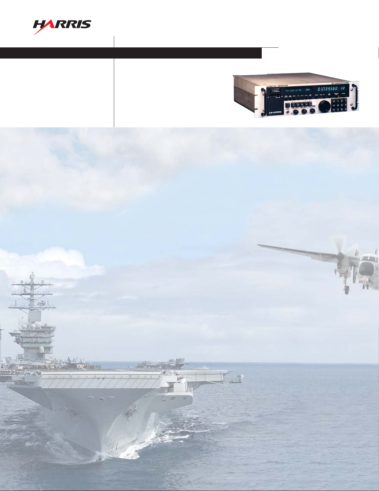
R-2368B(V)1/URR
RECEIVER
assuredcommunications
™
The R-2368B(V)1/URR is a high-performance, cost-effective, VLF/LF/MF/HF receiver
covering the frequency range from 10 kHz to 30 MHz in 1 Hz increments. Using
modern microprocessor control technology, this receiver provides the operational
es required for the professional communicator, while still maintaining the
featur
"touch" of the familiar tuning controls of older designs. The excellent RF performance
of the R-2368B(V)1/URR receiver, as exhibited by the superb intermodulation,
reciprocal mixing characteristics, and frequency agility, complement the unit's control
features in providing state-of-the-art communications capability.
The ability to enter and store up to 100 channels from the front panel or over remote
control, makes the R-2368B(V)1/URR a versatile communications tool for surveillance,
networking, or general purpose receiving. Each of the 100 channels may be
programmed for frequency, mode, IF; BW, BFO, FSK and AGC settings. The channels
may be scanned at variable rates, either sequentially or in programmed groups, with
the capability of being selected by the automatic scan control feature. An internal FSK
Demodulator is also provided.
The receiver contains a comprehensive built-in test equipment (BITE) network, which
allows extensive microprocessor-controlled self-testing to isolate faults at the modular
level. Surveillance BITE monitors the RF input, the power supply, and the
frequency stability.
Manual tuning and channel selection is activated via a front panel keypad or tuning
knob. Operating parameters such as detection mode, filter bandwidth (typically:
CW – 0.3 kHz, AM – 6 and 16 kHz, USB/LSB – 2.7 kHz, and FM – 16 kHz), and AGC
mode (Slow, Medium, Fast, Data, and Manual) are pushbutton selectable.
Receiver operating parameters and self-testing results are displayed on two front-panel
numeric and alphanumeric displays. Full remote control capability is accomplished with
an internal remote control system compatible with MIL-STD-188C, EIA Standard
RS-232C, or RS-422 formats.
The rear panel contains 50 ohm connectors for RF antenna input; filtered 455 kHz IF
output, unfiltered 455 kHz; ISB output; 5 MHz frequency standard inputs; and frequency standard output, local control lines, and other functions. The receiver is supplied with
rack mount kit including rack shock pins and shock blocks.
The R-2368B(V)1/URR offers a fully solid-state design with all components substantially
derated for long-term, dependable operation. This basic design concept coupled with
an extensive BITE self-diagnostics capability and modular packaging, result in rapid
maintenance by personnel with limited training.
The self-check sequence is automatically performed by momentarily pressing the TEST
button located on the front panel. Normal length of the self-test for all assemblies is
five seconds with all tests performed sequentially following the RF signal path. If it is
determined that a fault exists in a particular assembly, that assembly number and the
corresponding fault code number defining the type of failure are indicated on the
receiver's front-panel alphanumeric display. Because of the BITE system and modular
equipment design, demonstrated MTTR is less than ten minutes.
Page 2

®
Specifications for the R-2368B(V)1/URR
Electrical
Frequency Range 10 kHz to 29.999999 MHz
Frequency Resolution 1 Hz increments
Tuning Continuous, with lockout, with
Tuning Time Tuning time between any two
MTBF Greater than 6215 hours
Frequency Stability
Internal Standard 1 part in 10
Frequency Standard Input: 5 MHz, 0.5 VRMS;
Channel Memory 100-channel capacity capable of
Scanning Scan any set of consecutive channel
Automatic Scan Control Allows receiver to automatically stop
Readout/Display Receiver frequency, BFO frequency,
BFO 10 Hz synthesized tuning ± 9.99 kHz
Internal Preselector Digital operation, 20 dB attenuation
Maximum Signal Input Receiver protected for up to 100 watts at
Modes of Operation LSB, USB, 2-channel ISB, AM, CW, FM;
Link-11/TADIL-A With Delay-Compensated Filters
Operability
Sensitivity For 10 dB (S + N) : N radio
CW: 0.2 µV, 50 kHz – 30 MHz
AM
SSB: 0.6 µV, 50 kHz – 30 MHz
IF Bandwidths
Mode 3 dB BW (kHz)
CW
AM 6.0/16.0
USB 300 – 3050 Hz
LSB 300 – 3050 Hz
ISB (each channel) 300 – 3050Hz
seven selectable ranges and keypad entry.
frequencies is less than 20 msec
demonstrated per MIL-STD-781C
8
- OVEN
Output: 5 MHz, 0.5 VRMS/50 ohms
(daisy chain feature with automatic
frequency standard switchover)
being loaded locally or remotely
with complete receiver parameters.
Retention of operational parameters
without power is provided for one
month minimum
numbers (channel scan) or any of
ten preprogrammed sets of random
channel numbers (group scan)
scanning when a received signal
exceeds a predetermined threshold.
Scanning will resume automatically
when the signal falls below the
threshold or may be selected to
maintain the frequency.
channel assignment mode, IF/BW/filters,
AGC, BITE, dwell, scan, group,
FSK parameters
± 10% off frequency
the antenna input
Optional: 4-channel ISB, FSK with
internal modem or external modem
1.0 µV, 14 kHz – 50 kHz
1.6 µV, 10 kHz – 14 kHz
, 50 kHz – 30 MHz
V
µ
2.5
, 14 kHz – 50 kHz
V
µ
3.0
Standard supplied
0.15, 0.3, 1.0
16.0
FM
COR/Squelch Carrier Operated Relay with front panel
adjustable level set. Optional squelch thr
eshold
control.
Phase Stability Typically no greater than 2 degrees. Fully meets
Link-11 data requirements.
Intermodulation In-Band: -50 dB or better for two 100 mV
(-7 dBm) signals within the IF passband.
Out-of-Band: <10 dB (S + N) ÷ N for two –5 dBm
signals removed >10% from tuned frequency
Cross Modulation -20 dB or better for 500 mV 30% modulated
interfering signals r
emoved 20 kHz or greater
from the desired signal of 10 µV.
Reciprocal Mixing The apparent noise appearing at the receiver
input, when in a 3 kHz bandwidth, caused by a
0 dBm signal 100 kHz off tune, is less than 1.0
µV (-107 dBm).
Quieting Ultimate (S + N) ÷ N: 50 dB
Spurious Responses Image and IF: -100 dB; Spurious: Internal less
than –121 dBm equivalent except for seven less
than –101 dBm equivalent; External: -80 dB.
AGC Range: <3 dB audio output variation for 1 µV to 1
V signal range. (Thr
eshold internally adjustable
from 0.5 to 5 µV).
Time Constants;
Attack Time: <20 msecs;
Hang and Decay Time: Short <35 msecs,
Medium 200 ±50 msec, Long 2.5 ±0.5 secs;
Data: Link-11 compatible
Manual: 125 dB range
Audio Outputs Phone: +15 dBm/600 ohms/5% distortion
Line Output: -20 to +15 dBm, -26 dB distortion,
(optional +10 dBm 600 ohm balanced)/
Hum and Noise; less than 50 dB.
Pass Band Ripple: 3 dB max (optional internal
speaker).
IF Outputs 455 kHz (filtered and unfiltered)
Built-in Test Diagnostics Fault isolation to LRU with front-panel
alphanumeric indication
Remote Control An internal microprocessor-based system
capable of accepting asynchronous serial data
using the following formats: MIL-STD188C, EIA
Standard RS-232C and RS-422. Remote Control
protocol may be Harris proprietary or ASCII.
Remote control function allows interface to the
RF-7700NT Command and Control System, or
other control equipment. Remote Control
Functions: Frequency, Channel Select, IF BW,
Mode, AGC-TC, BFO, Fault-BITE Status,
Scan Select, RF Gain, AF Gain, RF and Audio Level
Status, and Channel Load, FSK Demod.
Installation
Power Requirements 115/230 VAC ±20%, 47 – 420 Hz, 90 watts max.
Size Rack mount and desk mount capability
5.25H x 19W x 19.5D (less fr
ont panel pr
ojections)
inches max.
(13.3H x 48.3W x 49.5D cm)
Weight 40 lbs (18.5 kg)
Environmental
Vibration MIL-STD-167-1, Type 1
Shock MIL-S-901; Grade A, Class 1, Lightweight, Type A
emperature Operating: -10°C to +55°C
T
Humidity 0 to 95%
(hard mount)
Non-Operating: -62
C to +71
°
°C
Specifications are subject to change without notice.
assured
communications
™
RF Communications Division | 1680 University Avenue | Rochester, NY USA 14610
www.harris.com 1-585-244-5830
Copyright © 2005 Harris Corporation 1/05 DS-317A
 Loading...