

Page 1
Operator’s Manual
MM-013994-001
Rev. J, October 2014
P7300 Series
Portable Radios
Page 2

MM-013994-001, Rev. J
REV
DATE
REASON FOR REVISION
Copyright © 2009-2014 Harris Corporation.
- Apr/09 Initial release.
A Oct/09 Updated the format of the manual to the Harris Corporate identity and improved consistency throughout the
B Jul/10 Added OpenSky support and SAR information for the 700/800 MHz portable radio. Added Immersion-Rated
C Apr/11 Updated for OTP 17; consolidated EDACS, Conventional, and P25 operation into one section.
D Oct/12 Added stealth mode and PIN entry (ECP R16A). Incorporated addendums. Added cleaning instructions.
E Dec/12 Updated parts list and caution in Section 7.
F May/13 Added Audio Playback, included OTP R20A features, updated OpenSky operation. Updated Options and
G Sep/13 Updated Options and Accessories table. Updated cleaning instructions.
H Mar/14 Updated Options and Accessories and data TX/RX indications; add Radio TextLink, view GPS information, and
J Oct/14 Updated for XGP R4A – added Voice Annunciation.
The software contained in this device is copyrighted by Harris Corporation Unpublished rights are reserved under the copyright laws of the United States.
This device is made under license under one or more of the following US patents: 4,590,473; 4,636,791; 5,148,482; 5,185,796; 5,271,017; 5,377,229;
4,716,407; 4,972,460; 5,502,767; 5,146,497; 5,164,986; 5,185,795; 5,226,084; 5,247,579; 5,491,772; 5,517,511; 5,630,011; 5,649,050; 5,701,390;
5,715,365; 5,754,974; 5,826,222; 5,870,405; 6,161,089; and 6,199,037 B1. DVSI claims certain rights, including patent rights under aforementioned U.S.
patents, and under other U.S. and foreign patents and patents pending. Any use of this software or technology requires a separate written license from DVSI.
Harris, OpenSky, and EDACS are registered trademarks and ProScan, Failsoft, and TECHNOLOGY TO CONNECT, INFORM AND PROTECT are
trademarks of Harris Corporation.
RBRC and 1-800-8-BATTERY are registered trademarks of Rechargeable Battery Recycling Corporation.
AMBE is a registered trademark and IMBE, AMBE+, and AMBE+2 are trademarks of Digital Voice Systems, Inc.
TORX is a registered trademark of CAMCAR division of TEXTRON, Inc.
All other product and brand names are trademarks, registered trademarks, or service marks of their respective holders.
The material contained herein is subject to U.S. export approval. No export or re-export is permitted without written approval f rom the U.S. Government.
Rated: EAR99; in accordance with U.S. Dept. of Commerce regulations 15CFR774, Export Administration Regulations.
Information and descriptions contained herein are the property of Harris Corporation . Such inf o r mation and descriptio n s may not be copied or reproduced by
any means, or disseminated or distributed without the exp ress prior written permission of Harris Corp oration, PSPC Business, 221 Jefferson Ridge Parkway,
Lynchburg, VA 24501.
manual with the documentation of the operation of the radio.
information.
Accessories table. Updated warranty.
Control and Status Services.
ACKNOWLEDGEMENTS
CREDITS!
NOTICE!
This product conforms to the European Union WEEE Directive 2012/19/EU. Do not dispose of this product in a public landfill. Take it to a
recycling center at the end of its life.
Harris products comply with the Restriction of the Use of Certain Hazardous Substances in Electrical and Electronic Equipment (RoHS)
Directive.
The voice coding technology embodied in this product is protected by intellectual property rights including patent rights, copyrights, and trade secrets of
Digital Voice Systems, Inc. The user of this technology is explicitly p rohibited from attempting to decompile, reverse engineer, or disassemble the Object
Code, or in any other way convert the Object Code into human-readable form.
Repairs to this equipment should be made only by an authorized service technician or facility designated by the supplier. Any repairs, alterations, or
substitution of recommended parts made by the user to this equipment not approved by the manufacturer could void the user’s authority to operate the
equipment in addition to the manufacturer’s warranty.
This manual is published by Harris Corporation, without any warranty. Improvements and changes to this manual necessitated by typographical errors,
inaccuracies of current information, or improvements to prog rams and/or equip ment, may be made by Harris Corporation, at an y time and withou t notice.
Such changes will be incorporated into new editions of this manual. No part of this manual may be reproduced or transmitted in any form or by any means,
electronic or mechanical, including photocopying and recording, for any purpose, without the express written permiss ion of Harris Corporation.
2
Page 3

MM-013994-001, Rev. J
1 SAFETY CONVENTIONS .................................................................................................................... 9
9.6.2 Display’s Second Line ................................................................................................... 30
TABLE OF CONTENTS
2 SAFETY TRAINING INFORMATION ............................................................................................ 10
2.1 RF EXPOSURE GUIDELINES ................................................................................................. 10
2.2 ELECTROMAGNETIC INTERFERENCE/COMPATIBILITY ............................................... 11
3 OPERATING TIPS .............................................................................................................................. 12
3.1 EFFICIENT RADIO OPERATION ........................................................................................... 12
4 CLEANING ........................................................................................................................................... 14
5 BATTERIES ......................................................................................................................................... 15
5.1 CONDITIONING BATTERY PACKS ...................................................................................... 15
5.2 CHARGING BATTERY PACKS .............................................................................................. 16
5.3 BATTERY PACK USAGE ........................................................................................................ 16
5.4 CHANGING THE BATTERY PACK ....................................................................................... 17
5.5 BATTERY DISPOSAL .............................................................................................................. 18
6 INTRODUCTION ................................................................................................................................ 19
6.1 WEATHERPROOF .................................................................................................................... 20
6.2 UNIVERSAL DEVICE CONNECTOR ..................................................................................... 20
7 OPTIONS AND ACCESSORIES ....................................................................................................... 21
8 CHANGE OPERATING MODE ........................................................................................................ 23
8.1 CHANGE FROM OTP MODE .................................................................................................. 23
8.2 CHANGE TO OTP MODE ........................................................................................................ 23
9 OPENSKY OPERATION .................................................................................................................... 24
9.1 CONTROLS ............................................................................................................................... 24
9.2 TRI-COLOR LED ...................................................................................................................... 28
9.3 LOG-IN TO THE NETWORK .................................................................................................. 28
9.4 LOG OFF THE NETWORK ...................................................................................................... 29
9.5 PERSONALITY ......................................................................................................................... 29
9.6 OPENSKY DISPLAY OVERVIEW .......................................................................................... 30
3.1.1 Antenna Care and Replacement ..................................................................................... 12
3.1.2 Electronic Devices ......................................................................................................... 12
3.1.3 Aircraft........................................................................................................................... 13
3.1.4 Electric Blasting Caps ................................................................................................... 13
3.1.5 Potentially Explosive Atmospheres ............................................................................... 13
5.1.1 Conditioning NiMH Battery Packs ................................................................................ 15
5.1.2 Conditioning NiCd Battery Packs ................................................................................. 15
5.1.3 Conditioning Lithium Battery Packs ............................................................................. 16
5.1.4 Storing Li-Ion Battery Packs ......................................................................................... 16
5.1.5 Additional Information .................................................................................................. 16
5.4.1 Removing the Battery Pack ........................................................................................... 17
5.4.2 Attaching the Battery Pack ............................................................................................ 18
9.1.1 Buttons, Knobs, and Switch .......................................................................................... 25
9.1.2 Keypad ........................................................................................................................... 26
9.1.3 Display ........................................................................................................................... 27
9.1.4
9.5.1 Profiles ........................................................................................................................... 29
9.5.2 Talk Groups ................................................................................................................... 30
9.6.1 Display’s Top Line ........................................................................................................ 30
Radio Status Icons ......................................................................................................... 27
Page
3
Page 4

MM-013994-001, Rev. J
9.6.3 Dwell Display ................................................................................................................ 30
9.28.2 Receiving an Emergency Call ....................................................................................... 49
TABLE OF CONTENTS
Page
9.7 ALERT TONES .......................................................................................................................... 31
9.8 BASIC MENU STRUCTURE.................................................................................................... 32
9.9 ERROR MESSAGES ................................................................................................................. 34
9.10 KEYPAD FUNCTION COMMANDS (P7370 ONLY) ............................................................. 36
9.11 QUICK KEYS (P7370 ONLY) .................................................................................................. 37
9.12 DTMF OVERDIAL .................................................................................................................... 37
9.13 LOCK/UNLOCK THE KEYPAD .............................................................................................. 37
9.14 DUAL-TONE MULTI-FREQUENCY (P7370 ONLY) ............................................................ 38
9.15 CHANGING THE ACTIVE PROFILE ..................................................................................... 38
9.16 CHANGING THE SELECTED TALK GROUP ....................................................................... 38
9.17 ADJUSTING DISPLAY AND BUTTON BACKLIGHT BRIGHTNESS ................................ 38
9.18 STEALTH MODE ...................................................................................................................... 38
9.18.1 Enabling Stealth Mode .................................................................................................. 38
9.18.2 Disabling Stealth Mode ................................................................................................. 38
9.19 ADJUSTING SIDE TONE AUDIO LEVEL ............................................................................. 39
9.20 CHANGE OPERATING MODE ............................................................................................... 39
9.20.1 From OTP to ECP Mode ............................................................................................... 39
9.20.2 From ECP to OTP Mode ............................................................................................... 40
9.21 RECEIVING AND TRANSMITTING VOICE CALLS ........................................................... 40
9.21.1 Receiving a Voice Call .................................................................................................. 40
9.21.2 Transmitting a Voice Call .............................................................................................. 40
9.22 ADJUSTING AUDIO TREBLE LEVEL ................................................................................... 40
9.23 TALK GROUP LOCK OUT ...................................................................................................... 41
9.23.1 Lock Out a Talk Group .................................................................................................. 41
9.23.2 Unlock a Talk Group ..................................................................................................... 41
9.24 SCANNING ................................................................................................................................ 42
9.24.1 Selecting Scan Modes .................................................................................................... 42
9.24.2 Checking or Changing Active Scan Mode .................................................................... 42
9.24.3 Scanning Priority ........................................................................................................... 43
9.24.4 Scan Mode A/B Switch ................................................................................................. 43
9.24.5 Scan Mode Quick Key (P7370 Only) ............................................................................ 44
9.25 MAKING SELECTIVE CALLS ................................................................................................ 44
9.25.1 Manually Dialing a Selective Call (P7370 Only) .......................................................... 44
9.25.2 Selective Call Using Speed Dial .................................................................................... 45
9.25.3 Accepting a Selective Call ............................................................................................. 45
9.25.4 Rejecting a Selective Call .............................................................................................. 46
9.25.5 Terminating a Selective Call ......................................................................................... 46
9.26 SELECTIVE ALERTS
9.26.1 Defining Messages......................................................................................................... 46
9.26.2 Sending a Message ........................................................................................................ 46
9.26.3 Receiving a Message ..................................................................................................... 47
9.26.4 Deleting a Selective Alert Message ............................................................................... 47
9.27 MAKING INTERCONNECT CALLS (P7370 ONLY) ............................................................. 48
9.28 EMERGENCY COMMUNICATIONS ..................................................................................... 48
9.28.1 Declaring an Emergency Call or Alert .......................................................................... 49
............................................................................................................... 46
4
Page 5

MM-013994-001, Rev. J
9.28.3 Dismissing an Emergency ............................................................................................. 49
10.18.1 Using the Menu Button .................................................................................................. 72
TABLE OF CONTENTS
9.28.4 Clearing an Emergency Call or Alert ............................................................................ 50
9.29 OPENSKY ENCRYPTION ........................................................................................................ 50
9.29.1 Automatic Encryption .................................................................................................... 50
9.29.2 A/B Switch .................................................................................................................... 51
9.29.3 Manual Encryption (P7370 Only) ................................................................................. 51
9.30 STATUS MESSAGES ............................................................................................................... 52
9.30.1 Send Status Message via the Keypad (System Model Radios Only)............................. 52
9.30.2 Send Status Message via the Menu ............................................................................... 52
9.31 REQUEST TO TALK (RTT) MESSAGES ............................................................................... 52
9.31.1 Send RTT Message via the Keypad (Sy ste m Model Radios Only) ............................... 52
9.31.2 Send RTT Message via the Menu .................................................................................. 53
9.32 SITE LOCK ................................................................................................................................ 53
9.33 GPS COORDINATES ................................................................................................................ 53
9.34 V-TAC OPERATION ................................................................................................................ 53
9.34.1 Extended Coverage Modes (XCOV, XCOV-TG, and XCOV-PROF) .......................... 53
9.34.2 Change Between Extended Coverage Modes ................................................................ 54
9.34.3 Radio Limitations Using Extended Coverage Modes .................................................... 54
9.34.4 Use XCOV Mode .......................................................................................................... 55
9.34.5 Use XCOV-TG Mode .................................................................................................... 55
9.34.6 Using XCOV-PROF Mode ............................................................................................ 56
9.34.7 Use Scene-of-Incident Mode ......................................................................................... 56
10 EDACS, CONVENTIONAL, P25 (ECP) OPERATION................................................................... 59
10.1 TURNING ON THE RADIO ..................................................................................................... 59
10.2 CONTROLS ............................................................................................................................... 59
10.2.1 Buttons, Knobs, and Switch .......................................................................................... 60
10.2.2 Keypad ........................................................................................................................... 61
10.3 DISPLAY ................................................................................................................................... 63
10.4 RADIO STATUS ICONS ........................................................................................................... 63
10.5 TRI-COLOR LED ...................................................................................................................... 65
10.6 STATUS MESSAGES ............................................................................................................... 65
10.7 ERROR MESSAGES ................................................................................................................. 66
10.8 ALERT TONES ......................................................................................................................... 67
10.9 VOICE ANNUNCIATION ........................................................................................................ 67
10.10 SYSTEM SELECTION .............................................................................................................. 67
10.11 GROUP/CHANNEL SELECTION ............................................................................................ 68
10.12 MODIFY SCAN LIST ............................................................................................................... 68
10.12.1 P7370 Model
10.12.2 P7350 Model .................................................................................................................. 69
10.13 MENU ........................................................................................................................................ 69
10.13.1 Menu Item Selection Process ......................................................................................... 69
10.14 BACKLIGHT ADJUST ............................................................................................................. 72
10.15 CONTRAST ADJUST ............................................................................................................... 72
10.16 DECLARING AN EMERGENCY ............................................................................................. 72
10.17 LOCKING/UNLOCKING KEYPAD ........................................................................................ 72
10.18 HIGH/LOW POWER ADJUSTMENT ...................................................................................... 72
.................................................................................................................. 68
Page
5
Page 6

MM-013994-001, Rev. J
10.18.2 Using the Pre-Programmed Option Button .................................................................... 73
10.32 AUDIO PLAYBACK ................................................................................................................. 88
TABLE OF CONTENTS
Page
10.19 ENCRYPTION ........................................................................................................................... 73
10.19.1 Displaying the Curren tly Used Cryptographic Key Number ......................................... 73
10.19.2 Key Zero ........................................................................................................................ 73
10.19.3 Receiving an Encrypted Call ......................................................................................... 74
10.19.4 Transmitting an Encrypted Call ..................................................................................... 74
10.20 SCAN OPERATION .................................................................................................................. 74
10.21 SYSTEM SCAN (EDACS AND P25 TRUNKED) ................................................................... 76
10.22 EMERGENCY OPERATION .................................................................................................... 78
10.23 STEALTH MODE ...................................................................................................................... 78
10.24 INDIVIDUAL CALLS (EDACS AND P25 M ODES) .............................................................. 79
10.25 TELEPHONE INTERCONNECT CALLS (EDACS AND P25 TRUNKED) .......................... 81
10.26 PRE-STORING INDIVIDUAL AND TELEPHONE INTERCONNECT CALLS FROM
10.27 STATUS/MESSAGE OPERATION (EDACS AND P25 MODES) ......................................... 84
10.28 DYNAMIC REGROUP OPERATION (EDACS) ..................................................................... 85
10.29 MACRO KEY OPERATION ..................................................................................................... 85
10.30 DATA (EDACS AND P25 MODES) ......................................................................................... 85
10.31 TYPE 99 OPERATION (ANALOG CONVENTIONAL) ......................................................... 87
10.20.1 Turning Scan On and Off .............................................................................................. 74
10.20.2 Add Groups and Channels to a Scan List ...................................................................... 75
10.20.3 Deleting Groups from a Scan List ................................................................................. 76
10.20.4 Nuisance Delete ............................................................................................................. 76
10.21.1 Wide Area System Scanning ......................................................................................... 77
10.21.2 Priority System Scan...................................................................................................... 77
10.21.3 ProScan .......................................................................................................................... 77
10.22.1 Receiving an Emergency Call ....................................................................................... 78
10.22.2 Declaring an Emergency Call ........................................................................................ 78
10.24.1 Receiving and Responding to an Individual Call .......................................................... 79
10.24.2 Sending an Individual Call ............................................................................................ 80
10.24.3 Call Storage Lists ........................................................................................................... 80
10.25.1 Receiving a Telepho ne Interconnect Call ...................................................................... 81
10.25.2 Sending a Telephone Interconnect Call ......................................................................... 81
10.25.3 Dual-Tone Multi-Frequency: Overdial .......................................................................... 82
THE KEYPAD ........................................................................................................................... 83
10.27.1 Status Operation ............................................................................................................ 84
10.27.2 Message Operation ........................................................................................................ 84
10.28.1 Emergency Operation .................................................................................................... 85
10.30.1 Displays ......................................................................................................................... 86
10.30.2 DATA OFF Operation ................................................................................................... 86
10.30.3 DATA ON Operation ....................................................................................................
10.30.4 Exiting Data Calls .......................................................................................................... 86
10.30.5 Scan Lockout Mode ....................................................................................................... 86
10.30.6 Data Lockout Mode ....................................................................................................... 87
10.31.1 Type 99 with or without Channel Guard ....................................................................... 87
10.31.2 Resetting Type 99 af ter a Call ....................................................................................... 87
10.31.3 Type 99 Disable after PTT ............................................................................................ 88
86
6
Page 7

MM-013994-001, Rev. J
10.33 RADIO TEXTLINK OPERATION ........................................................................................... 88
TABLE OF CONTENTS
10.33.1 Send TextLink Messages ............................................................................................... 88
10.33.2 View Received Text Link Messages .............................................................................. 88
10.33.3 Delete TextLink M essages ............................................................................................ 89
10.33.4 View the Current Time .................................................................................................. 89
10.34 VIEW GPS INFORMATION ..................................................................................................... 89
10.35 CONTROL AND STATUS SERVICES .................................................................................... 89
11 PREVENTIVE MAINTENANCE ...................................................................................................... 90
11.1 IMMERSIBLE P7300 PREVENTIVE MAINTENANCE ......................................................... 90
11.2 TECHNICAL ASSISTANCE – IMMERSIBLE P7300 ............................................................. 90
11.3 BASIC TROUBLESHOOTING ................................................................................................. 90
12 CUSTOMER SERVICE ...................................................................................................................... 92
12.1 CUSTOMER CARE ................................................................................................................... 92
12.2 TECHNICAL ASSISTANCE .................................................................................................... 92
13 WARRANTY ........................................................................................................................................ 93
FIGURES
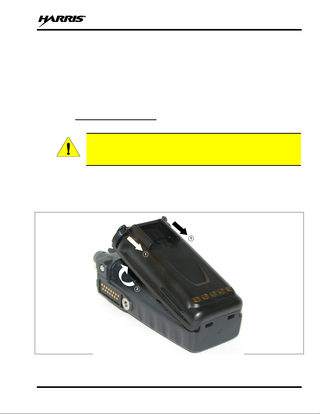
Figure 5-1: Removing the Battery Pack ......................................................................................................... 17
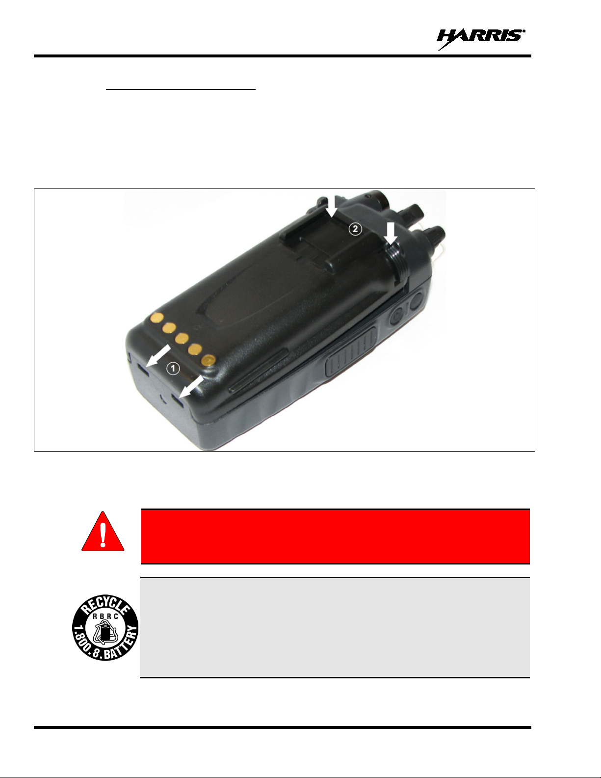
Figure 5-2: Attaching the Battery Pack .......................................................................................................... 18
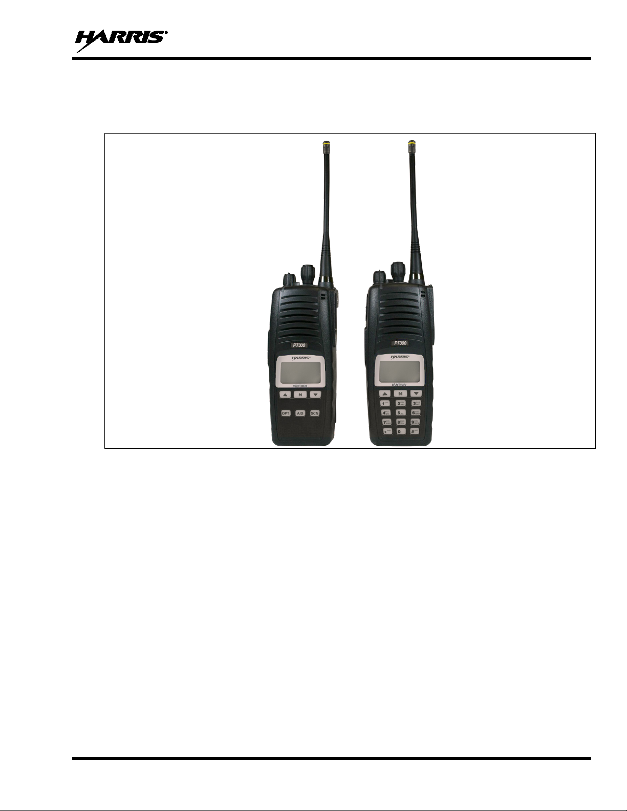
Figure 6-1: P7350 andP7370 Portable Radios ............................................................................................... 19
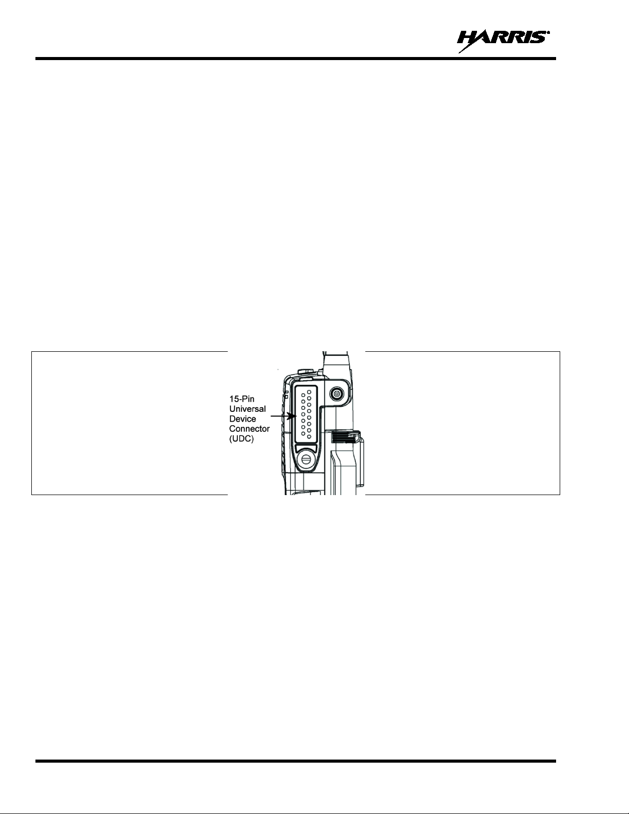
Figure 6-2: P7300 15-Pin Universal Device Connector ................................................................................ 20
Figure 9-1: Top View ..................................................................................................................................... 24
Figure 9-2: Side View .................................................................................................................................... 24
Figure 9-3: P7350 “Scan” Model Front Panel ............................................................................................... 26
Figure 9-4: P7370 “System” Model Front Panel ........................................................................................... 26
Figure 9-5: Sample Radio Display ................................................................................................................. 27
Figure 9-6: Full Cycle Battery Charge Indicator ........................................................................................... 28
Figure 9-7: Tri-Color LED ............................................................................................................................. 28
Figure 9-8: Personality Structure Example .................................................................................................... 30
Figure 10-1: Top View ................................................................................................................................... 59
Figure 10-2: Side View .................................................................................................................................. 59
Figure 10-3: P7350 “Scan” Radio Front Panel .............................................................................................. 61
Figure 10-4: P7370 “System” Radio Front Panel .......................................................................................... 62
Figure 10-5: P7300 Radio Display ................................................................................................................. 63
Figure 10-6: Full Cycle Battery Charge Indicator ......................................................................................... 64
Figure 10-7: Tri-Color LED ........................................................................................................................... 65
Figure 10-8: Menu Display ............................................................................................................................ 69
Figure 10-9: Backlight Menu Item Selection Parameter ................................................................................ 70
Figure 10-10: Backlight Menu Display
Figure 10-11: System Encryption Key Display ............................................................................................. 73
Figure 10-12: Group/Channel Encryption Key Display ................................................................................ 73
Figure 10-13: Calls Received Lists ................................................................................................................ 79
Figure 10-14: WHC Individual Call Display ................................................................................................. 80
Figure 10-15: Calls Received and Personality Lists ...................................................................................... 81
Figure 11-1: Labels ........................................................................................................................................ 90
......................................................................................................... 70
Page
7
Page 8

MM-013994-001, Rev. J
TABLE OF CONTENTS
Page
TABLES
Table 2-1: RF Exposure Compliance Testing Distances ............................................................................... 11
Table 7-1: Options and Accessories ............................................................................................................... 21
Table 9-1: Buttons, Knobs, and Switch Functions ......................................................................................... 25
Table 9-2: Keypad Functions ......................................................................................................................... 26
Table 9-3: Status Icons Descriptions.............................................................................................................. 27
Table 9-4: Alert Tones ................................................................................................................................... 31
Table 9-5: Basic P7300 OpenSky Menu Structure ........................................................................................ 32
Table 9-6: Keypad Function Commands ....................................................................................................... 36
Table 9-7: Quick Key Sequence .................................................................................................................... 37
Table 9-8: Scan Modes .................................................................................................................................. 42
Table 8-9: Status of Selective Call ................................................................................................................. 45
Table 8-10: Status of Selective Alert Messages ............................................................................................. 46
Table 9-11: Emergency Calls vs. Emergency Alerts ..................................................................................... 48
Table 9-12: Band Definitions ......................................................................................................................... 58
Table 10-1: Buttons, Knobs, and Switch Functions ....................................................................................... 60
Table 10-2: P7350 Keypad Functions ............................................................................................................ 61
Table 10-3: P7370 Keypad Functions ............................................................................................................ 62
Table 10-4: Status Icon Descriptions ............................................................................................................. 63
Table 10-5: Alert Tones ................................................................................................................................. 67
Table 10-6: Menu Item Information .............................................................................................................. 70
Table 10-7: Information Display .................................................................................................................... 71
Table 11-1: Troubleshooting .......................................................................................................................... 91
Harris Corporation, Public Safety and Professional Communications (PSPC) Business continually evaluates its
technical publications for completeness, technical accuracy, and organization. You can assist i n this process by
submitting your comments and suggestions to the following:
Harris Corporation
PSPC Business or fax your comments to: 1-434-455-6851
Technical Publications
221 Jefferson Ridge Parkway or e-mail us at: PSPC_techpubs@harris.com
Lynchburg, VA 24501
8
Page 9
MM-013994-001, Rev. J
Do not
proceed beyond a WARNING symbol until the conditions identified are fully
WARNING
CAUTION
NOTE
1 SAFETY CONVENTIONS
The following conventions are used throughout this manual to alert the user to general safety precautions
that must be observed during all phases of operation, service, and repair of this product. Failure to comply
with these precautions or with specific warning elsewhere in this manual violates safety standards of
design, manufacture, and intended use of the product. Harris assumes no liability for the customer’s
failure to comply with these standards.
The WARNING symbol calls attention to a procedure, practice, or the like, which, if
not correctly performed or adhered to, could result in personal injury.
understood or met.
The CAUTION symbol calls attention to an operating procedure, practice, or the like,
which, if not performed correctly or adhered to, could result in damage to the equipment
or severely degrade the equipment perfo r mance.
The NOTE symbol calls attention to supplemental information, which may improve
system performance or clarify a process or procedure.
The ESD symbol calls attention to procedures, practices, or the like, which could expose
equipment to the effects of Electro-Static Di scharge. Proper precautions must be taken to
prevent ESD when handling circuit modules.
The electrical hazard symbol indicates t here is an electrical hazard present.
9
Page 10
MM-013994-001, Rev. J
The Harris P7300 portable radio generates RF electromagnetic energy during
Only,” meaning it must be used only during the course of employment by
individuals aware of the hazards and the ways to minimize such hazards. This
radio is NOT intended for use by the “General Population” in an uncontrolled
To ensure that exposure to RF electromagnetic energy is within the FCC allowable
WARNING
CAUTION
2 SAFETY TRAINING INFORMATION
transmit mode. This radio is designed for and classified as “Occupational Use
environment.
The P7300 portable radio has been tested and complies with the FCC RF exposure limits for
“Occupational Use Only.” In addition, this Harris radio complies with the following Standards and
Guidelines with regard to RF energy and electromagnetic energy levels and ev aluation of such levels for
exposure to humans:
• FCC OET Bulletin 65 Edition 97-01 Supplement C, Evaluating Compliance with FCC Guidelines for
Human Exposure to Radio Frequency Electromagnetic Fields.
• American National Standards Institute (C95.1 – 1992), IEEE Standard for Safety Levels with Respect
to Human Exposure to Radio Frequency Electromagnetic Fields, 3 kHz to 300 GHz.
• American National Standards Institute (C95.3 – 1992), IEEE Recommended Practice for the
Measurement of Potentially Hazardous Electromagnetic Fields – RF and Microwave.
2.1 RF EXPOSURE GUIDELINES
limits for occupational use, always adher e to the following guidelines:
• DO NOT operate the radio without a proper antenna attach ed, as this may d amage the radio an d may
also cause the FCC RF exposure limits to be exceed ed. A p roper anten na is the anten na supp lied with
this radio by Harris or an antenna specifically authorized by Harris for use with this radio. (Refer to
Table 7-1.)
• DO NOT transmit for more than 50% of total radio use time (“50% duty cycle”). Transmitting more
than 50% of the time can cause FCC RF exposure compliance requirements to be exceeded . Th e rad io
is transmitting when the “TX” indicator appears in the display. The radio will transmit by pressing the
“PTT” (Push-To-Talk) button.
• ALWAYS transmit using low power when possible. In addition to conserving battery charge, low
power can reduce RF exposure.
• ALWAYS use Harris authorized accessories (an tennas, batteries, bel t clips, speaker/ mics, etc ). Use of
unauthorized accessories may cause the FCC Occupational/Controlled Exposure RF compliance
requirements to be exceeded. (Refer to Table 2-1.)
10
Page 11
MM-013994-001, Rev. J
Body
Face
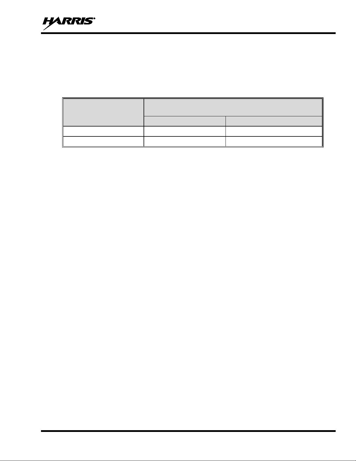
• As noted in Table 2-1, ALWAYS keep the device and its ant enna AT LEAST 1.1 cm (0.43 inches)
from the body and at least 2.5 cm (1.0 inch) from the face when transmitting to ensure FCC RF
exposure compliance requirements are not exceeded. However, to provide the best sound quality to
the recipients of your transmission, Harris recommends you hold the microphone at least 5 cm (2
inches) from mouth and slightly off to one side.
Table 2-1: RF Exposure Compliance Testing Distances
TESTED DISTANCES
RADIO FREQUENCY
450-512 MHz 1.1 cm 2.5 cm
700/800 MHz 1.1 cm 2.5 cm
The information in this section provides the information needed to make the user aware of RF exposure,
and what to do to assure that this radio operates within the FCC RF exposure limits of th is radio.
(worst case scenario)
2.2 ELECTROMA GNETIC INTERFERENCE/COMPATIBILITY
During transmissions, this Harris radio generates RF energy that can possibly cause interference with
other devices or systems. To avoid such interferen ce, turn off the radio in areas where sig ns are posted to
do so. DO NOT operate the trans mitter in areas that are sensitiv e to electromagnetic radiation such as
hospitals, aircraft, and blasting sites.
11
Page 12
MM-013994-001, Rev. J
may result if a damaged antenna comes into contact with the skin. Replace a
or attachments could cause damage to the radio unit and may violate FCC
RF energy from portable radios may affect some electronic equipment. Most modern
WARNING
WARNING
WARNING
CAUTION
3 OPERATING TIPS
Antenna location and condition are important when operating a portable radio. Operating the radio in low
lying areas or terrain, under power lines or bridges, inside of a vehicle or in a metal framed building can
severely reduce the range of the unit. Mountains can also reduce the range of the unit.
In areas where transmission or reception is poor, some improvement may be obtained by ensuring that the
antenna is vertical. Moving a few yards in another direction or moving to a higher elevation may also
improve communications. Vehicular operation can be aided with the use of an externally mounted
antenna.
Battery condition is another important factor in the trouble free operation of a portable radio. Always
properly charge the batteries.
3.1 EFFICIENT RADIO OPERATION
Keep the antenna in a vertical position when r ecei ving or transmitting a message.
Do not hold the antenna when receiving a message and, especially, do not hold when transmitting a
message.
Do NOT hold onto the antenna when the radio is powered on!
3.1.1 Antenna Care and Replacement
Do not use the portable radio with a damaged or missing antenna. A minor burn
damaged antenna immediately. Operating a portable radio with the antenna missing
could cause personal injury, damage the radio, and may violate FCC regulations.
Use only the supplied or approved antenna. Unauthorized antennas, modifications,
regulations. (Refer to Table 7-1.)
3.1.2 Electronic Devices
electronic equipment in cars, hospital s, homes, et c. is sh ielded from RF energ y. Howev er,
in areas in which you are instructed to turn off two-way radio equipment, always observe
the rules. If in doubt, turn it off!
12
Page 13
MM-013994-001, Rev. J
Areas with potentially explosive atmospheres are often, but not always, clearly
WARNING
WARNING
WARNING
3.1.3 Aircraft
• Always turn off a portable radio before boarding any aircraft!
• Use it on the ground only with crew permission.
• DO NOT use while in-flight!!
3.1.4 Electric Blasting Caps
To prevent accidental detonation of electric blasting caps, DO NOT use two-way
radios within 1000 feet of blasting operations. Always obey the "Turn Off Two-Way
Radios" signs posted where electric blasti ng caps are being used. (OSHA Standard:
1926.900)
3.1.5 Potentially Explosive Atmospheres
marked. These may be fuelling a reas, such as gas stations, fuel or che mical transfer
or storage facilities, and areas wh ere the air contains chemica ls or particles, such as
grain, dust, or metal powders.
Sparks in such areas could cause an explosion or fire resulting in bodily injury or
even death.
Turn OFF two-way radios when in any area with a potentially explosive atmosphere.
It is rare, but not impossible, that a radio or its accessories could generate sp arks.
13
Page 14
MM-013994-001, Rev. J
CAUTION
NOTE
4 CLEANING
Keep the exterior of the radio, battery, antenna, and radio accessories clean.
Periodically clean using the following procedures:
1. To remove dust and dirt, clean using damp clean cloth (warm water and mild detergent soap).
2. Follow by wiping with damp (warm water) clean cloth. Wipe dry with clean cloth.
3. Remove the battery and wipe the battery and radio contacts using a soft dry cloth to remove dirt or
grease. This will ensure efficient power tran sf er from the battery to the radio.
4. Remove any accessories and clean the accessor ies Univer sal Device Connector (UDC) contacts usin g
a clean dry cloth. When the UDC is not in use, co ver the connector with the protective dust cap to
prevent the build-up of dust or water particles.
5. If the radio is used in a harsh environment (such as driving rain, salt fog, etc.), it may be necessary to
periodically dry and clean the battery and radio contacts with a soft dry cloth or soft-bristle nonmetallic brush.
For more rigorous cleaning, use the foll owing procedure:
Do not use chemical cleaners, spray, or petroleum-based products. They may damage
the radio housing. We recommend using Chemtronics® Electro-Wash® PR (ES-1603) or
equivalent.
1. Apply the cleaning solution to a clean damp cloth and clean the radio.
Do not spray cleaning solution directly on radio. To clean the radio in the speaker and
microphone areas, carefully wipe these areas but prevent the cleaning solution from
entering the speaker or microphone openings.
2. Wipe off the radio with clean damp cloth usi ng mild warm soapy water.
3. Follow up by wiping off the radio with clean damp cloth using warm water only.
4. Wipe dry with clean cloth.
14
Page 15
MM-013994-001, Rev. J
WARNING
Harris authorized chargers and conditioners. Use of unauthorized chargers
lt in
WARNING
CAUTION
CAUTION
5 BATTERIES
The P7300 series portable radios use rechargeable, recyclable Nickel Cadmium (NiCd), Nickel Metal
Hydride (NiMH), Lithium-Ion (Li-Ion), and Lithium Polymer batter ies. Please carefully read the battery
information provided to maximize the useful life of each type of battery.
Do not disassemble or modify Lithium ba ttery packs. The Lithium battery packs
are equipped with built-in safety and protection features. Should these feat ures be
disabled or tampered with in any way, the battery pack can leak acid, overheat,
emit smoke, burst, and/or ignite.
If the battery is ruptured or is leaking electrolyte that results in skin or eye contact
with the electrolyte, immediately flush th e affected area with water. If the battery
electrolyte gets in the eyes, flush with water for 15 minutes and consult a physician
immediately.
Always use
and conditioners may void the warranty.
5.1 CONDITIONING BATTERY PACKS
5.1.1 Conditioning NiMH Battery Packs
Condition a new NiMH battery before putting into use. This also applies to rechargeable NiMH batteries
that have been stored for long periods (weeks, months, or longer). Conditioning requires fully charging
and fully discharging the battery three (3) times using the tri-chemistry charger. The first time the battery
is put into the charger, this unit will condition Nickel-based battery packs by automaticall y charging and
discharging (cycling) the battery. Refer to the appropriate charger manual for details.
Failure to properly condition NiMH battery packs before initial use will resu
shortened performance by the battery.
5.1.2 Conditioning NiCd Battery Packs
A new NiCd battery does not require conditioning before use. However, Harris recommend s periodically
conditioning NiCd batteries to avoid t he memory effect which results when a NiCd bat tery is repeatedly
charged and not fully discharged, further resulting in a lower voltag e and a lower capacity. Fortunately,
both nominal voltage and capacity are restored through battery conditioning.
Conditioning requires fully charging and fully discharging the battery three (3) times using the trichemistry charger. The first time the battery is put into the charger, this unit will condition Nickel-based
15
Page 16

MM-013994-001, Rev. J
battery packs by automatically chargi ng and discharging (cycling) the battery. Refer to the approp riate
charger manual for details.
5.1.3 Conditioning Lithium Battery Packs
Lithium-based battery packs do not suffer from memory effect and therefore do not require conditioning.
5.1.4 Storing Li-Ion Battery Packs
If a battery pack is expected to be idle for a month or more, it should be properly prepared. Li-Ion battery
packs should not be stored fully charged. Before storing the battery pack, discharge it to 40% capacity. If
the battery is not discharged prior to storage, i ts overall capacity may be reduced. Although all battery
packs experience some capacity loss during storage, the shelf life for Li-Ion battery packs is about 3
months. However, note that any capacity drop which occurs during storage is permanent and cannot be
reversed. Li-Ion battery packs should be purchased and used immediately. They should not be stockpiled without a rotating stock plan.
5.1.5 Additional Information
For more information regarding the proper care of portable radio battery packs or establishing a battery
maintenance program, refer to ECR-7367 which may be ordered by calling toll free 1-800-368-3277
(international - 1-434-455-6403) or via https://premier.pspc.harris.com/infocenter/.
5.2 CHARGING B ATTERY PACKS
Battery chargers are available fr om Harris with nominal charge times. Combination s include single and
multi-position charge units.
Harris chargers are specifically designed for charging Nickel-based and Lithium battery packs. The
chargers are chemistry-specific for the battery packs and automatically adjust the charging profiles
accordingly. Refer to the appropriate charger manual for specific operating instructions.
Observe the following guidelines when charging a battery pack:
• Avoid high temperature during charging.
• Discontinue use if the charger is overheating.
• Only charge Harris battery packs using a charger approved for use by Harris.
• Do not leave batteries in the charger indefi nitely. For best results, l eave the battery in t he charger for
two to six hours after the Green Ready LED comes on. Then place the battery pack into service and
fully discharge (as indicated by the radio lo w battery warning) before re-charging.
If any faults are encountered while charging the battery pack, con sult the charger’s manual to determine
the cause and possible corrective action.
5.3 BATTERY PACK USAGE
Both Nickel-based and Lithium batteries vary in capaci ty and life cycle. For instance, Ni Cd batt eries have
a longer life cycle than NiMH batterie s whereas NiMH batteries have a larger capacity. Howev er, both
Nickel-based and Lithium type batteries require basic usage g uidelines be followed in order to optimize
the battery runtime or shift life.
16
The following guidelines will help optimize the battery runtime or shift life:
Page 17
MM-013994-001, Rev. J
Although the P7300 has been designed to tolerate changing the battery pack without
CAUTION
• Ensure Nickel-based battery packs are fully discharged (as indicated by the radio low battery
warning) before re-charging. Full discharge is not required for Lithium battery packs.
• Periodically condition Nickel-based battery packs. The frequency should be determined based on
usage patterns (refer to ECR-7367). If the battery is fully discharged (to radio Low Battery warning)
during routine use, the frequency of conditioning may be reduced. Lithium batteries do not suffer
from memory-effect and therefore do not require conditioning.
Do not leave any Harris rechargeable bat teries in a charger for more than a few days.
5.4 CHANGING THE BATTERY PACK
5.4.1 Removing the Battery Pack
Make sure the power to the radio is turned OFF.
turning power off, Harris recommends turning the radio off before changing battery packs
to ensure safety and best operation.
1. Press or pull both latches on either side of the battery pack toward the bottom of the radio
simultaneously.
2. Pull the battery away from the radio.
3. Remove the battery pack from the radio.
Figure 5-1: Removing the Battery Pack
17
Page 18
MM-013994-001, Rev. J
you have
useful life, under various state and local laws, it may be illegal to dispose of this
for information and/or procedures for
WARNING
5.4.2 Attaching the Battery Pack
Make sure the power to the radio is turned OFF.
1. Align the tabs at each side on the bottom of the battery pack with the slots at the bottom of the battery
cavity .
2. Push the top of the battery pack down until the latches click to attach the battery to the radio.
3. Tug gently to verify that the latches are secure and the battery pack is properly attached to the radio.
Figure 5-2: Attaching the Battery Pack
5.5 BATTERY DISPOSAL
In no instance should a battery be incinerated. Disposing of a battery by burning
will cause an explosion.
RECHARGEABLE BATTERY PACK DISPOSAL – The product
purchased contains a rechargeable batt ery. The battery is recyclable. At the end of i ts
battery into the municipal waste stream. Check with you r local solid waste officials for
details in your area for recycling options or proper disposal. Canadian and U.S. users
may call Toll Free 1-800-8-BATTERY®
returning rechargeable batteries in y our locality.
18
Page 19
MM-013994-001, Rev. J
6 INTRODUCTION
The P7300 series portable radio is availabl e in two mo dels: th e P7350 Scan model wi th a li mited 6 -button
front-mounted keypad and the P7370 System model with a 15-button DTMF front-mounted keypad.
Figure 6-1: P7350 andP7370 Portable Radios
The Harris P7300 portable radio delivers end-to-end encrypted digital voice and IP data communications.
It is designed to support multiple operating modes including:
• EDACS
• OpenSky
®
(Enhanced Digital Access Communication s System) or ProVoice™ Trunked Modes
®
Trunked Protocol (OTP)
• P25 Trunked Mode
• P25 Digital Conventional Mode
• Conventional Analog Mode
The P7300 portables can include all of these modes or just one. Additional modes of operation can be
added with software updates.
The P7300 supports a full range of advanced digital trunking features, including Talk Group calls, priority
scanning, emergency calls, late call entry , and dynamic reconf iguration. It p erforms autonomou s roaming
for wide area applications. High quality voice coding and robust audio components assure speech clarity.
In the trunked modes, the user selects a communicati ons “operating” system (i.e., EDACS, ProVo ice, or
P25) and group. While communicating in a trunked mode, channel selection is transparent to the user and
is controlled via digital communication with the system controller (e.g., a CSD in an EDACS system).
This provides advanced programmable features and fast access to communication channels.
19
Page 20
MM-013994-001, Rev. J
In Conventional Analog mode, the user selects a ch annel and communicates directly on that chan nel. A
channel is a transmit/receive radio frequency pair.
The exact operation of the radio depends on the operating mode, the radio’s programming, and the
particular radio system. Most features described in this manual can be enabled through programming.
Consult your System Administrator for the particular features programmed into your P7300. Then refer
to the corresponding section(s) within this manual for feature and operation information.
6.1 WEATHERPROOF
The P7300 series radios operate reliably un der adverse conditions. These portable radios meet military
standards MIL-STD-810F specifications for high and low operating and storage temperatures, low
pressure extremes, thermal shock, solar radiation, driven rain, humidity, salt fog, blowing dust, shock, and
vibration.
6.2 UNIVERSAL DEVICE CONNECTOR
The Universal Device Connector (UDC) provid es connections for external accessories such as a h eadset,
a speaker-microphone, audio test box, audio test cables, and programming cables. The UDC is located o n
the right side of the radio, opposite the PTT Button. The UDC facilitates programming and testing the
radio. The UDC pins perform different functions depending on the accessory attached to the UDC.
20
Figure 6-2: P7300 15-Pin Universal Device Connector
Page 21
MM-013994-001, Rev. J
arris authorized accessories (antennas, batteries, belt clips,
speaker/mics, etc). Use of unauthorized accessories may cause the FCC
Occupational/Controlled Exposure RF compliance requirements to be exceeded.
ANTENNAS
Half Wave Whip Antenna, 806-870 MHz
KRE 101 1506/1
MAEV-NNC5K
Wideband Whip, 764-870 MHz
KRE 101 1506/2
MAEV-NNC5X
Helical Stub 470-512 MHz
KRE 101 1219/14
MAEV-NNC5Y
¼ Wave Whip 440-512 MHz
KRE 101 1223/12
MAEV-NNC1N
Antenna, 764-870 MHz, Flex, End-Fed, Hi Gain
14002-0223-01
EV-NC7A
BATTERIES
Nickel Cadmium (NiCd) Battery, Immersible
BT-023406-001
MAEV-NPA9W
Nickel Cadmium (NiCd) Battery, Immersible, [FM]
BT-023406-002
MAEV-NPA9Z
Nickel Metal Hydride (NiMH) Battery, Immersible
BT-023406-003
MAEV-NPA9X
Nickel Metal Hydride (NiMH) Battery, Immersible, [FM]
BT-023406-004
MAEV-NPA2A
Lithium-Ion (Li-Ion) Battery, Immersible
BT-023406-005
MAEV-NPA9Y
Lithium Polymer Battery, 3600 mAH
BT-023436-001
MAEV-PA2U
AUDIO ACCESSORIES
Speaker Mic without Antenna (cc) provision, [FM]
MC-023933-001
MAEV-NAE9D
Rugged Speaker Mic, Antenna, Strai ght, SBR
MC-011617-602
MAEV-NAE6D
Earphone for Speaker Mic, [FM]
LS103239V1
MAEV-NAE3Z
Earphone for Speaker Mic, Right A ngle Jack
LS103239V2
EV-AE1K
GPS
MC-009104-002
MAEV-NAE9R
Ruggedized Speaker Mic-Coil Cord
MC-011617-601
MAEV-NAE6C
Standard Speaker Mic - Non Ant
MC-011617-701
MAEV-NAE6A
Rugged Speaker Mic, Coiled Cord, Hi -Visibility
MC-011617-606
EV-AE4C
Speaker Mic, Straight Cord, 25.6in, A ntenna
MC-011617-703
MAEV-AE6L
Speaker Mic, Antenna, Straight, 18in
MC-011617-718
MAEV-AE6M
Speaker Mic, Antenna, Straight, 30in
MC-011617-730
MAEV-AE6N
Speaker Mic, Rugged, Coiled, Hir os e Port
MC-011617-611
EV-AE4K
DROP SHIP AUDIO ACCESSORIES
Earphone Kit, Black
EA-009580-001
Earphone Kit, Beige
EA-009580-002
2-Wire Kit, Palm Mic, Black
EA-009580-003
2-Wire Kit, Palm Mic, Beige
EA-009580-004
WARNING
CAUTION
7 OPTIONS AND ACCESSORIES
Table 7-1 lists the Options and Acces sories tested for use with the P730 0 series portable radios. Refer to
the Harris Products and Services Catalog for a complete list of options and accessories, including those
items that do not adversely affect the RF energy exposure.
Always use H
(Refer to Table 2-1.)
Always use the correct options and accessories (bat tery , anten na, speaker/ mic, etc.) for th e
radio. Immersion rated options must be used with an immersion rated radio. Intrinsically
safe options (identified by [FM]) are certified by Factory Mutual (FM) and must only be
used with FM certified radios. (Refer to Table 7-1.)
Table 7-1: Options and Accessories
DESCRIPTION PART NUMBER OPTION NUMBER
21
Page 22

MM-013994-001, Rev. J
3-Wire Kit, Mini-Lapel Mic, Black
EA-009580-005
3-Wire Kit, Mini-Lapel Mic, Beige
EA-009580-006
Explorer Headset with PTT
EA-009580-007
Lightweight Headset Single Speaker with PTT
EA-009580-008
Breeze Headset with PTT
EA-009580-009
Headset, Heavy Duty, N/C Behind-the-Head, with PTT
EA-009580-010
Ranger Headset with PTT
EA-009580-011
Skull Mic with Body PTT and Earcup
EA-009580-012
Headset, Heavy Duty, N/C Over-the-Head, with PTT
EA-009580-013
Throat Mic with Acoustic Tube and Bod y PTT
EA-009580-014
Throat Mic with Acoustic Tube, Body PTT, and Ring PTT
EA-009580-015
Breeze Headset with PTT and Pigtail Jac k
EA-009580-016
Hurricane Headset with PTT
EA-009580-017
Hurricane Headset with PTT and Pigtail Jack
EA-009580-018
CARRYING CASE ACCESSORIES
14011-0012-03 includes:
CC-014527
14011-0012-04 includes:
CC-014524-001
Belt Clip, Standard
CC23894
MAEV-NHC2G
T Strap Holder
MAEV-NHC2J
Belt Loop, Leather with Swivel
KRY 1011 609/1
FM-017262-001
Case, Black Nylon, with Belt Loop
14011-0012-01 includes:
CC-014527
Case, Orange Nylon, with Belt Loop
KT-016201-002
MAEV-NHC2B
Strap, Leather Retaining
CC-014524-002
MAEV-NHC2E
DESCRIPTION PART NUMBER OPTION NUMBER
Case, Leather with Bel t Loop
Case, Leather, with Shoulder Strap
14011-0011-03
FM-017262-001
14011-0011-04
FM-017262-001
14011-0011-01
MAEV-NHC2C
MAEV-NHC2D
MAEV-NHC7T
MAEV-NHC2A
22
Page 23

MM-013994-001, Rev. J
8 CHANGE OPERATING MODE
8.1 CHANGE FRO M OTP MODE
To change from OTP operating mode to EDACS/P25/Conventional (ECP):
1. Use or
2. Use or to choose an available mode. Press and or to confirm (Y/N).
3. Press the button to confirm.
Or
With a system model radio, press 1# to transition to ECP.
Or
If configured, turn the A/B Switch to the A or B position.
to cycle through the menu until “App Mode” is displayed.
8.2 CHANGE TO OTP MODE
1. Use or to scroll through available systems un til OpenSky is displayed and wait.
2. The radio transitions to OTP mode.
23
Page 24
MM-013994-001, Rev. J
9 OPENSKY OPERATION
Once an OpenSky system has been selected from the available systems on your P7300 series portable
radio, the characteristics described in the following sections will govern operation.
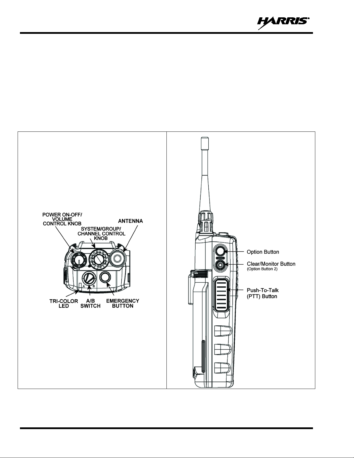
9.1 CONTROLS
The P7300 portable radios feature two rotary control knobs, an emergency button, and a dual-position
A/B switch located on the top of the radio (Figure 9-1). The Push-To-Talk (PTT) button and two option
buttons are located on the side (Figure 9-2) of the radio. The front mounted keypad of the P7370
“System” model has 15 buttons and the P7350 “Scan” model has six buttons. Refer to Figure 9-3 and
Figure 9-4, respectively.
24
Figure 9-1: Top View Figure 9-2: Side View
Page 25
MM-013994-001, Rev. J
and
Rotating the control clockwise applies power to the radio. Rotating the control clockwise increases the
volume level. Minimum volume levels may be programmed into the radio to prevent missed calls due
he display will momentarily indicate the volume
KNOB
(A minimum time that the emergency button must
be pressed may be configured into the radio before an emergency is declared. Check with your System
press the emergency button. Release both buttons when the “emergency cleared”
BUTTON 1
A/B SWITCH
e encrypted disable voice encryption on
is voice encrypted enable voice encryption on
transmit.
9.1.1 Buttons, Knobs, and Switch
The functions of the buttons, knob controls, and dual position A/B Switch vary depending on the mode of
operation. Their functions while in the OpenSky mode of operation are discussed in Table 9-1.
Table 9-1: Buttons, Knobs, and Switch Functions
POWER
ON-OFF
VOLUME KNOB
TALK GROUP
SELECTION
EMERGENCY
BUTTON
PTT BUTTON
SIDE OPTION
SIDE OPTION
BUTTON 2
The Power On-Off/Volume Knob is rotated to apply power to the radio and adjust audio volume up
down.
to a low volume setting. While adjusting the volume, t
level (e.g., VOL=39). The volume range is from a minimum programmed level of 1 (displayed as OFF
in the display) up to 39, which is the maximum level.
Used to select Talk Groups when operating within an OpenSky system. This is a 16-position rotary
knob.
Press the emergency button to declare an emergency.
Administrator.) To clear an emergency, if programmed to do so, press and hold the Option 2 button .
While holding ,
tone sounds.
The Push-To-Talk button must be pressed before voice transmission begins.
Scrolls UP or DOWN thru available items within a sub-menu, such as available Talk Groups, preprogrammed speed dial numbers, canned alert messages, etc.
The following settings are configurable via the at@abcswitch command:
• N o Action.
• V-TAC Detach (same as *60).
• V-TAC Attach (same as *61, *62, or *62 depending on at@cmode setting).
• Change to ECP mode.
• Scan Mode - No Scan (See Section 9.24.1).
• Scan Mode - Normal (See Section 9.24.1).
• Scan Mode - Fixed (See Section 9.24.1).
• Voice Encryption OFF - If the Selected Talk Group is voic
transmit.
• Voice Encryption ON - If the Selected Talk Group
25
Page 26
MM-013994-001, Rev. J
KEY
FUNCTION
Primary function: Acts much as an “enter” button to activate a selection.
, and
channel.
(P7370 Only)
but it clears everything, not onl y t he last digit/character).
numeric keys for passwords and OpenSky
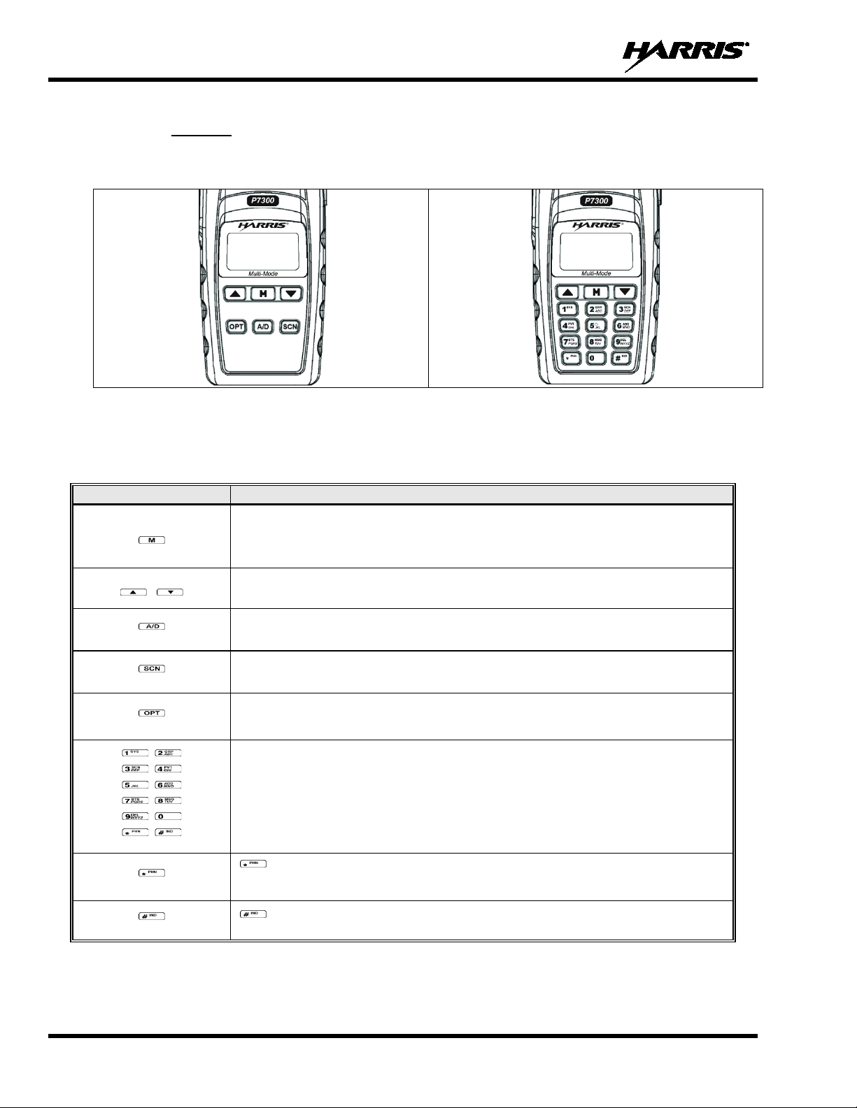
9.1.2 Keypad
The front mounted keypad of the P7350 “Scan” model has six buttons and P7370 “System” model has 15
buttons. Refer to Figure 9-3 and Figure 9-4, respectively.
Figure 9-3: P7350 “Scan” Model Front Panel Figure 9-4: P7370 “System” Model Front Panel
In OTP mode, numeric entry is the primary function of the keys. Each key is described in Table 9-2.
Table 9-2: Keypad Functions
(P7350 only)
(P7350 only)
(P7350 only)
(P7370 Only)
(P7370 Only)
Secondary function: While in the “d well display,” press repe atedly to scroll throug h and
view status display (on 2
Scrolls thru available menu items ( s ee Table 9-5).
Currently undefined in OpenSk y mode.
Toggles scan mode On/Off.
Currently undefined in OpenSk y mode.
The alpha-numeric keys are used t o ent er a l pha-numeric passwords for logging into the
OpenSky network, if not pre-configured for automatic registration at power-up.
Also used to place telephone int erconnect and individual (unit-to-unit) call s, operating
like a normal telephone keypad. Additiona l functions are also av ailable, such as speed
dial, quick access to V-TAC, voice scanning, and Stealth mode operation.
Initiates OpenSky functions (log-in, log out, selective call, telephone interconnect
call, etc.). It is also used as an escape or to cl ear an entry (someth ing like backspace,
Used in conjunction with alpha-
functions to end a command string.
nd
line) for current profile, caller, received Talk Group
26
Page 27
MM-013994-001, Rev. J
STATUS ICON DESCRIPTIONS
OPENSKY ICONS
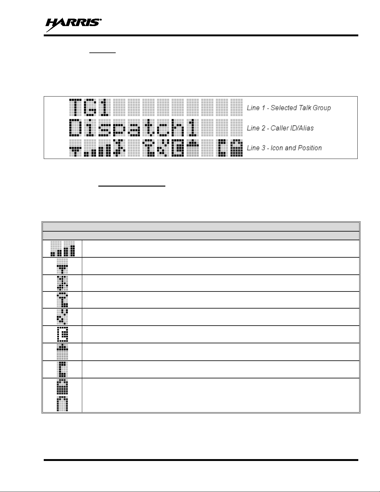
9.1.3 Display
The P7300 display is made up of 3 lines. Lines 1 and 2 contain twelve alpha-numeric character blocks
each. The 3
rd
line also contains twelve blo cks, each u sed to disp lay radi o stat us i co ns. If p rog ra mmed, t he
display backlighting will illuminate upon power-up or when radio controls are operated. Specific display
characteristics will be discussed in following sub-sections.
Figure 9-5: Sample Radio Display
9.1.4 Radio Status Icons
Status Icons indicate the various operat ing characteristics of the radio. The icons sho w operating modes
and conditions and appear on the third line of the display (see Table 9-3).
Table 9-3: Status Icons Descriptions
Steady – Received Signal Strength Indicator (RSSI).
Steady – Radio is data registered.
Steady – Stealth mode is enabled, all tones and the display backlight are disabled, voice is still heard.
Steady – Radio is transmitting or receiving an encrypted voice call.
Animated – The radio is scanning for a V-TAC. Once the radio has attached to a V-TAC, the icon will turn off.
V-TAC Connection Indicator – Indicates the client is connected to a V-TAC.
Steady – Indicates Voice Scan mode is Normal or Fixed. Is not displayed when Voice Scan mode is No Scan.
Steady – Indicates Selective Call mode.
Steady – Battery charge indicator.
Flashing – Low battery indicator.
27
Page 28
MM-013994-001, Rev. J
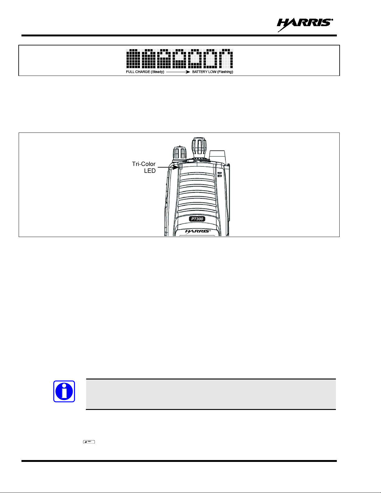
NOTE
Figure 9-6: Full Cycle Battery Charge Indicator
The battery charge indicator illustrates approximate charge only, based on battery voltage. Refer to
Figure 9-6.
9.2 TRI-COLOR L ED
Figure 9-7: Tri-Color LED
The Tri-Color LED changes color to indicate radio status and is visible from both the front and top of the
radio (see Figure 9-7).
In OpenSky mode the following radio states are ref l ected by the LED and the status they represent are:
Green: Receiving
Red: Transmitting
Orange: If the LED is flashing rapidly, the radio is receiving an emergency call. If the
LED is flashing every ½ second, the selected Talk Group is in the emergency
state (although not transmitting). I f the selected Talk Group is in the emergency
state, an asterisk will be displayed next to t he Talk Group name.
9.3 LOG-IN TO THE NETWORK
Log-in occurs either automatically (auto registration) if the radio has a valid registration or, if enabled,
requires the user to enter a User ID and password.
The user will be prompted with “Pls Login” if one Talk Group in the selected profile
can be encrypted. The user has to log-in to use that Talk Group in encrypted mode.
1. Press *1.
2. Enter the full 10-digit User ID.
3. Press the key.
28
Page 29

MM-013994-001, Rev. J
in assistance and/or
NOTE
4. Enter the password.
• If the radio is configured for alpha-numeric passwords and the password has consecutive
duplicate numbers (“MES33” for example), enter #, the key, between the consecutive
duplicate numbers so the radio will not interpret t he entry as a letter (“D” in this example).
• If the radio is configured for numeric-only passwords, do not press the key between
duplicated numbers.
5. Press the key twice for alphanumeric passwords or once for numeric only passwords.
The User ID may be remembered from the previous log-in. (Refer to Section 9.4 for further details
regarding log-off commands.) The password will be established before the radio is put into operation.
Contact the local OpenSky network administrator for more information.
If necessary, contact radio system administration personnel for logradio-specific log-in instructions.
9.4 LOG OFF THE NETWORK
The *0## command de-registers the radio. Typically, this is automatically performed when powering
down the radio. Using this method, the User ID is remembered by the radio so only the password is
needed at next log-in.
If a user is logged in, it is preferable to log-o f f to prevent unnecessary network resources being used.
9.5 PERSONALITY
As illustrated in Figure 9-8, a personality defines the profiles and Talk Groups available to the user. It is
the structuring of a collection of profiles and privileges established by the OpenSky network administrator
to provide the user with a comprehensiv e set of profiles to communicate effectively with the necessary
Talk Groups or individuals.
Personalities are stored on the network and downloaded over-the-air to the radio. This process is called
“provisioning.” Provisioning occurs at radio power-up (if the personality is not already stored in the
radio’s memory) and at user log-in (if the radio has been deregistered). When changes are made to the
personality, the radio is automatically re-provisioned. Each personality can contain up to sixteen (16)
profiles and each profile can contain up to sixteen Talk Groups.
9.5.1 Profiles
As stated above, each profile can contain up to sixteen (16) Talk Groups. A profile also defines the
radio’s emergency behavior. All transmissions are ma de on the sel ected Talk Group (displayed on the top
line of the dwell display). The user ca n change the selected Talk Group to any of the other Talk Groups
within the profile.
29
Page 30

MM-013994-001, Rev. J
TG a
TG b
TG c
TG x
TG y
TG z
TG d
TG e
TG f
TG a
TG d
TG g
TG h
TG i
TG = Talk Group
Profile 1
Profile 2
Profile 3
Figure 9-8: Personality Structure Example
9.5.2 Talk Groups
A Talk Group represents a set of users that regularly need to communicate with one an other. There can
be any number of authorized users assigned t o a Talk Group. Talk Groups are established and organized
by the OpenSky network administrator. An OpenSky Talk Group is similar to a channel within a
conventional FM radio system.
9.6 OPENSKY DISPLAY OVERVIEW
The 12-character x 3-line display shows the radio status. The first two lines of th e display are text lines
that change in response to user interaction with the menu buttons. Status icons appear in the bottom line
(line 3) of the display (see Table 9-3).
9.6.1 Display’s Top Line
The display’s top line of text changes as the and buttons are pressed to scroll through the
available menu options (see Table 9-5). When the dwell display is present, the selected Talk Group will
be displayed. Other information, such as alert messages, will scroll across the top line of the display.
9.6.2 Display’s Second Line
The second line will display information su ch as activ e menu, log-in prompt, emergency status, and dwell
display messages as described in Section 9.6.3.
9.6.3 Dwell Display
When not engaged in menu selection, the first two lines of the display default to the user-defined display,
known as the “dwell display.” The to p line indicates the curren tly selected Talk Group. The second line
will display the currently selected profile, caller ID/alias
if the channel menu is enabled. Press the button repeatedly to scroll through and view one of these
second line options.
1
, received Talk Group, and current channel name
1
Alias is a logical ID name such as “J_Smith.” The name corresponds to a user ID such as 003-542-0001.
30
Page 31

MM-013994-001, Rev. J
NAME
TONE
DESCRIPTION
Call Queued
One low tone/two high tones
Call is queued for processing.
active.
second grant tone to let the user know they have roamed.
coverage area or pre-empted by higher-priority call).
pitched
network drops the call if unans wered after one (1) minute.
If enabled via programming, sounds at a programmable interval
Menu.
Sounds when a radio connects to a V-TAC in XCOV, XCOV-
Menu.
pitched tone
Sounds when the man down accessory is connect to the radio’s
9.7 ALERT TONES
The P7300 radio also provides audible Alert Tones or “beeps” to indicate the various operating conditions
(see Table 9-4).
Table 9-4: Alert Tones
Call Denied Three short beeps
Grant (or Go-Ahead) Single short beep
Call Removed Single long low-pitched tone
Low Battery
Selective Alert Received Four short tones
Emergency Alert Tone Three long beeps Sounds when an emergency alert is declared.
Emergency Cleared Tone Single long low-pitched tone Sounds when an emergency is cleared.
Selective Call Ring Tone
Roam Tone
One low-pitched/one short mid-
A ringing tone similar to a
telephone
Two short tones, one highpitched and one low-pitched
Radio is out of coverage area or requ ested Talk Group is
Sounded when resources become available for a call request
placed in the queue (if enabled) upon c hannel access.
If the radio roams to another site whil e transmitting, then it will
auto rekey and begin transmitting on t hat tower. It gives a
Notifies the user access to the channel has been lost (out of
Low battery.
Only played once to indicate a selective alert has been
received.
Ringing is repeated every four (4) seconds until the call is
accepted or rejected by the radio bein g called or until the
Sounds when the radio transitions from one radio base station
site to another. While transmitting voice.
Out of Range Tone Three brief tones
Priority Bump Single medium mid-pitched tone
XCOV Connect Tone
or
Site Found Tone
XCOV Disconnect Tone
or
Site Not Found Tone
Man Down Tone
Three short high-pitched tones
Three short high-pitched tones
Single long low-pitch tone
followed by a single short high-
while the radio is in a state of persistent deactivation.
Sounds when the current received ca ll is preempted by a
higher priority call.
Sounds when a radio connects to a V-TAC in XCOV, XCOV-
TG, or XCOV-Prof mode.
Sounds when the selected site is found using the Site Lock
TG, or XCOV-Prof mode.
Sounds when the selected site is not f ound using the Site Lock
UDC port and the radio is a horizontal.
31
Page 32

MM-013994-001, Rev. J
MENU
NAME
RADIO
DISPLAYS
To/From Dwell
Display
bit-error rates,
registration status
Silent
Emergency
and
confirm (Y/N) with or and again.
to base station [“GPS (Site)”] or
Station
Identification
Stealth Mode
is disabled)
for more
.
Display
Brightness
to
See Next Page
9.8 BASIC MENU STRUCTURE
Table 9-5 illustrates the basic P7300 OpenSky menu structure. Menu items will vary depending upon
system programming, radio hardware, and optional configurations. All menus except the dwell display
menu can be turned off by network administration personnel.
Table 9-5: Basic P7300 OpenSky Menu Structure
USAGE NOTES
Engineering
Display
Operating Mode
GPS Fix
User ID
IP Address
RSSI data, sync
status, current
channel and
“SilentEmerg”
“App Mode”
“GPS”
“User ID”
“IP Address”
“Station ID”
Displays radio system connection data. For engineering use.
Use or to toggle between OFF/ON. Press to enable.
Use or to choose an available mode (
GPS latitude and longitude position of currently tunedV-TAC (“GPS”) scrolls across top line of the display. “GPS (Aged)” indicates V-TAC
coordinates haven’t been updated f or more that 2 minutes.
User’s identification/name scrolls across top line of the display (if programm ed).
Radio’s Internet Protocol (IP) address scrolls across top line of the display.
Station’s identification/name scrolls across top line of the display (if progra mmed).
OTP, OCF, or ECP). Press
(display backlight
Treble Level
Side Tone Level
32
“StealthMenu”
“Treble Menu”
“Bright Menu”
“Side Menu”
Use or to turn Stealth Mode “On” or “Off.” See Section 8.17
information about Stealth Mode.
Use or to choose speaker treble level (LOW, MEDIUM, MEDHIGH, or HIGH)
Press to return to dwell display.
Use or to brighten or dim backlighting. Press to return to dwell display.
Use or to choose side tone level (OFF, LOW, MED, or HIGH). Press
return to dwell display.
Page 33

MM-013994-001, Rev. J
MENU
NAME
RADIO
DISPLAYS
See Previous Page
Selected
Channel
.
to toggle “<”
Talk Group
Priority 1
all
to go to the “Alert Msg” menu.
to send message and
to return to dwell
Use or to tog gle status led “On” or “Of f.” When On, the LED flashes red when
the radio transmits, green when rec eiving, a nd amber when in emergenc y. When Off,
the LED will not light at all.
Use or to scroll through available messages. Press to send the selected
message.
Request to Talk
Message
Use or to scroll through available messages. Press to send the selected
message.
V-TAC Client
Emergency
Dismiss
” on (dismiss)
and off.
See Next Page
USAGE NOTES
Scan Mode
Talk Group
Lock Out
Priority 2
Talk Group
Alerts Received
Alert Destination
“ChannelMenu”
“ScnModeMenu”
“LockOutMenu”
“Priority2”
“Priority1”
“Alerts Rcvd”
or oldest message
“Alert Dest”
Displays the current channel. Press to return to dwell display.
Use or to scroll through available scan m odes (Normal, No Scan, or Fixed)
Press to return to dwell display.
Use or to choose a Talk Group for locking/unlock ing. Press
on (locked out) and off.
Use or to choose Priority 2 Talk Group. Press to return to dwell display.
Use or to choose Priority 1 Talk Group. Press to return to dwell display.
“No alerts” or alert message text scrolls in display. Use or to scroll through
messages.
Use or to choose a speed-dial num ber. Press
Use or to scroll through “canned mess ages. ” Press
return to dwell display.
Speed Dial
Profile Selection
Talk Group
Selection
Status LED
Status Message
Mode
“Speed Dial”
“ProfileMenu”
“TalkGrpMenu”
“Status LED”
“Status Msg”
“RTT Msg”
“Client Mode”
“EmgDismiss”
Use or to choose a speed-dial number and press P TT to place call.
Use or to choose an available profile. Press to ret ur n to dwell display.
Use or to choose a Talk Group in current profile. Press
display.
Use or to choose Client Mode (Network, XCOV, XCOV-TG, or SOI).
Use or to cho ose emer genc y Talk Grou p. Press to toggl e “<
33
Page 34

MM-013994-001, Rev. J
MENU
NAME
RADIO
DISPLAYS
See Previous Page
OTP Software
Version
to reset RF
diagnostics counters.
Group
)
and off.
Use and to scroll through menus.
MESSAGE
DESCRIPTION
conditions, contact your system administrator.
your system administrator.
UNAUTH3
Unauthorized IP. The radio network ID has not been added to network.
system administrator.
your system administrator.
system administrator.
DUP IP
Duplicate IP.
BADIKEY
Invalid infrastructure public key sequence number (IPKSN).
BADEKEY
Invalid end-system public key sequence number (EPKSN).
conditions, contact your system administrator.
contact your system administrator.
contact your system administrator.
MDS BSY
MDIS busy – retry.
USAGE NOTES
Site Lock
RF Diagnostics
Priority 3 Talk
“Site Lock”
“Software Ver”
“Diagnostics”
“Priority 3”
Use or to scroll through sites. Press to select site.
Displays OTP software version Press t o return to dwell display.
Use or to scroll through RF diagnostics displays. Press
Use or to choose Pr iority 3 Talk Group. Press to toggle “<” on (selected
9.9 ERROR MESSAGES
This section lists and describes the erro r messages that may be displayed by the radio durin g OpenSky
operation.
NOAUT01
MDENIED
Unspecified MDIS (data switch) error. If condition persists in strong signal
Unspecified MDIS error. If condition persists in strong signal conditions, contact
UNAUTH4
UNAUTH5
MDISBSY
UNK MES
NOAUT05
BADMDIS
Bad authentication. If condition persists in strong signal conditions, contact your
Unsupported authentication. If condition persists in strong signal conditions, contact
The MDIS is busy. If condition persists in strong signal conditions, contact your
Unknown mobile end system (MES); i.e., radio. If condition persists in strong signal
MDIS failed mutual authentication. If condition persists in strong signal conditions,
MDIS failed mutual authentication. If condition persists in strong signal conditions,
34
Page 35

MM-013994-001, Rev. J
MESSAGE
DESCRIPTION
your system administrator.
KEYSYNC
Mismatched key sequence number.
UNK ALG
Unknown/unsupported encryption algorithm.
BADSIZE
Unsupported MDIS key size.
If condition persists in strong signal
conditions, contact your system administrator.
your system administrator.
If condition persists in strong signal conditions,
contact your system administrator.
If condition persists in strong signal
conditions, contact your system administrator.
BAD VID
Invalid voice User ID. Check User ID. If correct, contact your system administrator.
Retry. If error continues, contact your system
administrator.
SRV BSY
The serving VNIC is busy (congested).
*0## command or power down one of the other radios to de-register the radio.
NAS BSY
The system cannot provision radio because of an administrative process.
contact TAC (see Section 12.2).
conditions, contact your system administrator.
signal conditions, contact your system administrator.
PLS LOGIN
Log-in with keypad.
BAD PWD
An invalid password has been entered. Verify the password and re-enter.
exceeds an
Report this failure to authorized technician.
No App
ECP mode is unavailable (not programmed).
NO PRIV
Missing required privilege.
conditions, contact your system administrator.
Dead battery
Radio must shutdown because battery charge is critically low.
NO REG
Not registered with MDIS, VNIC, or both.
UNK DOM
NOAUT11
NOAUT12
NOREPLY
VDENIED
HOM DWN
MAX USR
Unknown home domain. If condition persists in strong signal conditions, contact
Radio failed data mutual authentication.
No response from MDIS. If condition persists in strong signal conditions, contact
No SME response from MDIS.
Unspecified VNIC (voice switch) error.
The Home VNIC is down.
The maximum users are already registered with the specified User ID. OpenSky
allows one User ID to log onto the network using up to three different radios. Use
NOAUTHM
NOSUPRT
NOAUTHV
OVER_TEMP
NO SYNC
The radio failed voice mutual authentication. If a valid radio displays this error,
The radio cannot support the required provision. If condition persists in strong signal
VNIC does not support or failed mutual authentication. If condition persists in strong
The radio may be too hot. The radio will cease transmitting if it
operational temperature threshold. Let the radio cool before attempting to transmit.
No forward-channel sync (weak or no coverage). If condition persists in strong signal
35
Page 36

MM-013994-001, Rev. J
MESSAGE
DESCRIPTION
DISABLED
Function disabled (e.g., function invalid in current context).
*0
Log-off command: *0## (logs the user off the system ). See Section 9.4 for additional informatio n.
additional information.
*2
Status Message: *2 <0...9> #.
Exit SOI Mode with *40#
*5
RTT Message: *5 <0...9> #.
additional information.
*8
Radio-to-Radio Call command: *8<Selective call number>#(PTT to dial).
dial) See Section 9.27 for additional information.
1-16 digit encryption key for 128 bit encr yption; 17-32 digit encryption key for 256 bit enc ryption.
*33
End Manual Encryption command: *33#
*61
Initiate XCOV Mode: Extended coverage for individu al users.
*62
Initiate XCOV-TG Mode: Extended coverage for Talk Groups.
*63
Initiate XCOV-PROF Mode command: *63#.
*60
Exit XCOV or XCOV-TG Mode: Returns to the Network mode.
9.10 KEYPAD FUN CTION COMMANDS (P7370 ONLY)
To perform a command from the keypad, use the keypad commands in Table 9-6.
Table 9-6: Keypad Function Commands
COMMANDS FUNCTION
*1
*4
*7
*9
*32
Log-in command: *1<User ID> # <Password> ## (required for encryption). See Section 9.1.3 for
Enter Scene of Incident Mode (SOI) on specified channel and band: *4#<Chan>#<Band>#
where Chan is the channel number that i s being used as a SOI repeater and band is the number
assigned to each frequency band. F or example, if Channel 25 800 MHz (band 0) is being used for
SOI, then enter *4#25#0#.
Initiate Selective Alert command: *7<Target ID>#[Choose Message]#. See Section 9.26 for
Public Switched Telephone Network (PSTN) Call command: *9 <telephone number>#(PTT to
Begin Manual Encryption command: *32<Pre-determined Encryption Key>#
36
Page 37

MM-013994-001, Rev. J
QUICK
KEYS
Transition to ECP Mode
If ECP code is not loaded in the radio, “No App” appears in the display.
2#
Toggles Stealth Mode On/Off
Toggles Scan Mode On/Off (Normal/Fixed, see details below)
toggled On.
Lights/Tones On/Off
If the radio is in Stealth mode, this quick key is disabled since the user is not able to turn on the
light/tones in stealth mode.
This quick key sequence is used to set the current active profile to the default profile in the personality as
defined in the UAS.
XCOV & XCOV-TG Attach/Detach
TAC, the
will attempt to attach to another V-TAC.
7#
This quick key sequence is used to tr ansmit the RTT Automatic Normal Message to the cons ole.
8#
This quick key sequence is used to tr ansmit the RTT Automatic Priority Message to the c onsole.
9.11 QUICK KEYS ( P7370 ONLY)
Quick Keys are a two-button sequence that provides the user with quick access to certain menu items.
Quick Keys function as a toggle for these menu items.
Table 9-7: Quick Key Sequence
1#
• If the Scan Mode is Normal when the Scan Mode is toggled Off, the Scan Mode will be Normal when
toggled On again.
3#
4#
• If the Scan Mode is Fixed when the Scan Mode is toggled Off, the Scan Mode will be Fixed when
scan mode is toggled On again.
• If the Scan Mode is Off when the radio boots up, the Scan Mode will be Normal when Scan Mode is
Pressing 4# turns the TX/RX LEDs, B ac klight, and Side Tones On/Off.
If any of the TX/RX LEDs, Backlight, and/or Side Tones are On, and this quick ke y sequence is used,
then all of the TX/RX LEDs, Backlight , and Side Tones are turned Off.
FUNCTION
5#
6#
9.12 DTMF OVERDIAL
Using the keypad on a System Model, the radio can transmit DTMF tones corresponding to
numbers/characters 0 - 9, *, and # on the keypad. To overdial numbers/characters, transmit by pressing
and holding the PTT button and then, press the corresponding keys (one at a time) on the keypad.
9.13 LOCK/UNLOCK THE KEYPAD
This quick key sequence is used t o manually connect to a V-TAC. When attaching to a Vradio’s programming determines whether to attach to the V-TAC in XCOV or XCOV-TG mode.
• I f the user attaches to a V-TAC manually, using the *61# or *62# command sequenc e, the radio is
understood to be attached and this quick key sequence will detach the radio from the V-TAC.
• If the user detaches manually from a V-TAC using the *60# command sequence, the radio is
understood to be detached and this qu i c k key sequence will attach the radio to a V-TAC.
• A t bootup, t he radi o is under st ood to be det ac hed from a V-TAC. If a radio automatically attaches to
a V-TAC, the radio is still und erstood to be det ached from a V-TAC and will attempt to attach to a VTAC.
• I f a radio manuall y attaches to a V-TAC and then is automatically detached from a V-TA C, the radio
1. Press and hold the button.
2. Within 1 second, press the Option button on the side of the radio.
37
Page 38

MM-013994-001, Rev. J
9.14 DUAL-TONE MULTI-FREQUENCY (P7370 ONLY)
Dual-Tone Multi-Frequency (DTMF) is the system used by touch-tone telephones. DTMF assigns a
specific set of tone frequencies to each key . This allows for specific tasks such as entering a user ID and
password, or selective calling. When a key on the DTMF keypad is pressed, the DTMF tone is played
through the radio’s speaker.
9.15 CHANGING T HE ACTIVE PROFILE
The radio can store up to sixteen (16) standard profiles, one of which is the currently active profile. To
change the currently active profile:
1. Press the or buttons until ProfileMenu is displayed.
2. Then use or
3. A Profile becomes active when selected fo r longer than 2 seco nds, when the is pressed, or when
the menu is changed using the or
to scroll through the list of available profiles.
button. Press to activate the selected profile.
9.16 CHANGING T HE SELECTED TALK GROUP
Each profile stored in the radio can have up to sixteen (16) Talk Groups. One Talk Group within the
currently active profile is set as the “selected Talk Group.” To change the selected Talk Group, turn the
Group Selection knob on top of the radio or use the Talk Group selection menu.
9.17 ADJUSTING DISPLAY AND BUTTON BACKLIGHT BRIGHTNESS
1. Press the or buttons until Bright Menu is displayed.
2. Use to toggle display backlighting on and to toggle display backlighting off.
9.18 STEALTH MODE
For some users, it is important to be able to turn off the radio’s display lights and side tones, but not the
radio traffic. For example, in covert operations, lights and sounds could inadvertently expose an
otherwise unobservable radio user. For this purpose, the radio has a Stealth feature that disables the radio
display lights, indicator lights, and audible alert and side tones.
When Stealth Mode is on, the radio continues to scan the programmed list of Talk Groups and the user
can key-up on the selected Talk Group.
38
9.18.1 Enabling Stealth Mode
P7370 only: Quick Key combination 2# toggles Stealth Mode on and off.
Both models: Press the or buttons to scroll through menus until StealthMenu appears in the
display. To immediately activate Stealth Mode, press the or button once. This activates Stealth
Mode, exits the Stealth Menu, and returns to the Dwell Display.
The display lights, indicator lights, and side tones are disabled. The stealth mode icon is displayed.
9.18.2 Disabling Stealth Mode
P7370 only: To re-enable all lighting, side tones and exit Stealth Mode, press Quick Key combination 2#
again. The radio returns to the Dwell Display.
Page 39

MM-013994-001, Rev. J
NOTE
NOTE
Stealth Mode can also be disabled by using the Stealth Menu.
P7350 only: To re-enable all lighting, side tones and exit Stealth Mode, press the or buttons or
the button. The radio returns to the Dwell Display.
The display lights, indicator lights, and side tones are re-enabled. The stealth mode icon disappears.
9.19 ADJUSTING SIDE TONE AUDIO LEVEL
The radio sounds confirming tones called “side tones” when its buttons are pressed. Most users find this
audible confirmation helpful when navigating the menus. Side tone audio level can be adjusted or turned
completely off using the “Side Menu” or the Quick Key combination #4.
Quick Key combination #4 turns off the backlight in addition to the side tones. Unlike
Stealth Mode, alert tones can still be heard.
For covert operations, it may be necessary to turn off side tones. For safety’s sake, turning off the radio
during covert operations is not recommended.
If the radio is operating properly but side tones are not heard when the menu buttons are pressed, the side
tones are probably turned off. To turn them back on, acces s the “Side Tone” menu and select a setting
other than “off.”
Use the following procedure set side tone level:
1. Press the or buttons to cycle through the menu until Side Menu is displayed.
2. Press or to change to the desired level (Off, Low, Medium, and High). To turn side tones off
completely, use the “Off” setting.
9.20 CHANGE OPERATING MODE
9.20.1 From OTP to ECP Mode
Method 1 (Quick Key, P7370 only):
1. Press 1#. If ECP is not loaded in the radio, the radio displays “No App.”
Method 2:
To change from OTP operation to ECP operation using the menu, perform the following steps:
1. Press the or
2. Press or to select the desired operation mode.
3. Press and use or to select Y or N.
4. Press to make selection and return to the dwell display.
5. “Restart Please Wait” appears in the disp lay as the radio switches modes.
buttons to cycle through the menu until “App Mode” is displayed.
Method 3:
If configured, turn the A/B Switch to the A or B position.
39
Page 40

MM-013994-001, Rev. J
NOTE
9.20.2 From ECP to OTP Mode
Press the or buttons to cycle through available systems until OPEN SKY appears in the display.
Pause briefly and the radio will switch automatically from ECP to OTP operation.
9.21 RECEIVI NG AND TRANSMITTING VOICE CALLS
As soon as the radio completes the initializatio n sequence an d registers o n the Open Sky network , the user
will begin to hear calls from the Talk Groups in the active profile, if available.
9.21.1 Receiving a Voice Call
No action is required to receive a voice call . The display responds to incoming voice calls as follows:
• When the dwell display is set to received Talk Group and the scan mode is Normal o r Fixed:
a. If the received Talk Group matches the select ed Talk Group, then the alias (if avai lable) or user
ID of the incoming caller is displayed.
b. If the received Talk Group does not match the selected Talk Group, then the received T alk Group
name is displayed.
• When the dwell display is set to received Talk Group and the scan mode is None, the radio only
receives voice on its selected Talk Group. When the call is r eceiv ed , t he ali as ( if avail abl e) or t h e u ser
ID of the incoming caller is displayed.
• When the dwell display is not set to received Talk Group, then there is no display indication of an
incoming call.
A radio receiving a System All Call, Regency All Call, or an Agency All Call displays
“All Call” instead of the alias. A radio not transmitting on a Talk Group in emergency
status will drop all other calls to scan into an All Call.
9.21.2 Transmitting a Voice Call
1. Select the desired Talk Group.
2. Press and hold the PTT button, wait a couple of seconds. If programmed by the administrator, a
grant tone will sound.
3. Begin speaking into the microphone in a normal voice.
4. For maximum clarity, hold the radio approximately 2 inches from your mouth. Take care not to cover
up the microphone while speaking.
5. Release the PTT button to terminate an outgoing voice call.
9.22 ADJUSTING AUDIO TREBLE LEVEL
The tone of received signals can be adjusted using the radio’s “Treble Menu.”
1. Press the or buttons to cycle through the menu until Treble Menu is displayed.
2. Press or to increase or decrease l evel. There are four levels available: low, mediu m, medium-
high, and high.
3. Press or wait a few seconds to return to the dwell display.
40
Page 41

MM-013994-001, Rev. J
NOTE
NOTE
NOTE
9.23 TALK GROUP L OCK OU T
There are two ways to focus voice communic ations by suppressing calls from Talk Groups in the active
profile.
• No Scan. By changing the Scanning Mode to No Scan only the selected Talk Group is scanned.
• Lock Out. By locking out selected Talk Groups, background noise or chatter can be eliminated and
scanning resources can be focused on just those groups whose calls you wish to monitor.
Lock out is a listening (receive) function and only blocks received calls on locked out
Talk Groups. Lock out does not affect transmit capability. “No Scan” and “Lock Out” do
not apply to recent emergency lock outs.
Only Talk Groups in the active profile can be locked out, since they are the only Talk Groups whose
voice calls can be heard on the radio. Talk Group lock out is a scan-related feature. With lock out, one or
more Talk Groups in the activ e profile can be temporarily disabled from being scanned. Call s are not
received on locked-out Talk Groups. Lock out settin gs are not retained between profile changes.
P1, P2, and P3 groups CANNOT be locked out.
The default emergency and emergency-capable Talk Groups can be locked out if they are NOT in an
emergency state. If a Talk Group is locked out and is subsequently changed to the currently selected Talk
Group, it will automatically be unlocked by the radio so the user can hear calls on the Talk Group. The
radio may be configured so all Talk Groups are automatically locked out by default. In this case, they
must be manually unlocked, if desired.
9.23.1 Lock Out a Talk Group
1. Use the or buttons to scroll through the menu choices until LockOutMenu appears in the
display.
2. Use the or keys to scroll through the list of Talk Groups, if any, until the user group you want to
lock out appears in the display.
3. Press the key to select the lockable Talk Group.
4. < appears next to the locked out Talk Group.
9.23.2 Unlock a Talk Group
1. Use the or buttons to scroll through the menu choices until LockOutMenu appears in the
display.
2. Use the or keys to scroll through the list of Talk Groups, if any, until the user group you want to
unlock appears in the display.
3. Use the key to unlock the displayed Talk Group.
• Changing the active profile removes any lockouts you have made.
• Turning off the radio removes any lockouts you have made.
41
Page 42

MM-013994-001, Rev. J
9.24 SCANNING
9.24.1 Selecting Scan Modes
Three scanning modes are available for the radio, but only one can be active at any time. Changing the
scanning mode changes the way the radi o scans voice calls for all of the profiles in the radio per sonality,
no matter which profile is or becomes active.
The choice of scanning mode broadens or narrows the span of communications with all the groups in
profiles you listen to, but does not affect your interaction with those groups you talk with.
The scanning modes available for selec tion may be limited by the administrator to a subset of the three
scanning modes.
Table 9-8: Scan Modes
SCAN
MODE
None
Normal
(Default)
Fixed
EXPLANATION
Eliminates distractions.
Full communications (listen and t al k ) with the selected Talk Group.
No calls received from other T alk Groups.
The user can scan all Talk Groups in the act ive profile that ar e not locked out as long as there is demand on
the site.
Priority (P1, P2, and P3) groups are user selectable.
Receive calls from more than one Talk Group, if available from the current site.
Allows dragging of the select ed Talk Group, P1, P2, P3, and emer gency Talk Group (in emergency state) to
the site on which the radio is registered. (If other calls are available at the site, they also can be heard but they
will not be actively dragged.)
The default emergency Talk Group, as well as any emerg ency-enabled Talk Groups, is only dragged if it is in
emergency mode.
Functions the same as Normal Scan Mode, except the priority groups are fixed to the selected profile’s predefined P1 and P2 groups (configured via the UAS).
The scanning mode choice remains in effect until it is changed. Even if the radio is turned off, the current
scanning mode selection is saved for the next use.
9.24.2 Checking or Changing Active Scan Mode
9.24.2.1 Setting the Scan Mode
42
1. Press the or buttons until ScnModeMenu appears in the display.
2. Use the or keys to scroll through the list of modes until your choice appears: Normal, None, or
Fixed.
3. Press the key to activate the scan mode selection and return to the dwell display.
9.24.2.2 Duration of Scanning Mode Selections
Scanning Mode selections survive power down. At startup, the radio defaults to the scanning mode of set
during last use. The last selection mad e remains in effect until a new selection is made from the Scan
Mode menu.
Page 43

MM-013994-001, Rev. J
are saved
NOTE
9.24.3 Scanning Priority
The following lists the scanning priority order (from highest to lowest):
• Selected Talk Group in emergency state.
• Default emergency group in emergency state.
• Selected Talk Group.
• Emergency capable group in emergency state.
• Priority 1 Talk Group.
• Priority 2 Talk Group.
• Priority 3 Talk Group.
• Other (non-priority).
9.24.3.1 Changing Scan Priority
1. Press the or keys until Priority 1 or Priority 2 appears in the d isplay (Priority 1
group has higher priority than the Priorty 2 group).
2. Press the or button until the desired Talk Group is displayed.
3. Press the key to select and activate the selectio n. The radio automatically return s to the Dwell
Display.
• Changing the priority of a listen group does not change your Talk Group.
• Priority can be set for six Talk Groups (Priority 1, Priority 2, and up to four Priority 3),
but only in the selected profile.
• If the save settings is configured for the radio, scanning priority settings
when the radio is turned off. Otherwi se, they are reset to the default values when the
radio is turned off.
9.24.3.2 Changing Scan Priority 3 Talk Groups
1. Use the or buttons to scroll through the menu choices until “Priority 3” appears in the
display.
2. Use the or keys to scroll through the list of Talk Groups, if any, until the user group you want to
set as Priority 3 appears in the display.
3. Press the key to select a Priority 3 Talk Group.
4. “<” appears next to the Priority 3 Talk Group.
9.24.4 Scan Mode A/B Switch
The A/B switch can be configured to toggle Scan Mode On/Off.
If the Scan mode icon (see Table 9-8) is On; either the Normal or Fixed Scan modes are enabled,
depending on programming. If the Scan mode icon is not displayed, Scan mode is set to No Scan.
43
Page 44

MM-013994-001, Rev. J
NOTE
NOTE
9.24.5 Scan Mode Quick Key (P7370 Only)
Press 3# to toggle Scan mode on and off.
If the Scan mode icon (see Table 9-3) is displayed, either the Normal or Fixed Scan modes are enabled,
depending on programming. If the Scan mode icon is not displayed, Scan mode is set to No Scan.
9.25 MAKING SELECTI VE CA LLS
Selective calling is the capability for two voice radio units to obtain and use an independent talk path for a
unit-to-unit call. A properly equipped radio can initiate a selective call to any radio in the system that is
also programmed for selective calls.
In the OpenSky system, a radio can be co nfigu red to in itiate sele cti ve calls th roug h a pre-programmed list
in memory called a speed dial list. Alternatively, a prop erly configured radio can initiate a selective c all
to any radio in the system by ent ering the ten-digit User ID (similar to a telephone number) of the tar get
radio. Some radios are configured to only receive (not initiate) selective calls.
Selective calls are terminated if an emergency is declared. The network limits selective
calls to ten (10) minutes maximum.
If a Selective Call is attempted without physical registration, No Priv is displayed.
9.25.1 Manually Dialing a Selective Call (P7370 Only)
1. Enter *8, the User ID number of the user being called, and the # key (no dashes or spaces). Note that
this feature must be enabled by the administrator.
*8<destination user id>#
A shortened User ID number can be dialed using the following guidelines:
• If the radio being called is in the same region and agency – enter only the last four digits.
• If the radio being called is in the same region, but a different agency – enter the last seven digits.
• If the radio being called is in another region or if the area is unknown – enter all ten digits.
2. Press the PTT (and release) to ring the other user.
The ring tone is sounded.
If the other user accepts the call, the called user’s alias will ap pear in initiating caller’s display. The
two are now in a unit-to-unit call until one ends the call, the call is terminated due to an initiated
emergency, or the maximum time limit of ten ( 10) minutes is reached.
If the called radio is busy, BUSY will appear in the second line of the display.
44
Page 45

MM-013994-001, Rev. J
MESSAGE
DEFINITION
Busy
Peer is involved in another selective/PSTN call.
Disconnect
Selective/PSTN call was terminated for unknown reason.
Network Err
Selective/PSTN call cannot conti nue because of an unspecified network error.
Reject
Peer or this user declined request to establish selective/PSTN call.
Unavailable
Peer cannot be reached for selective/PSTN call.
Calling
Calling peer (i.e., for selective or PSTN calls).
Connecting
Establishing selective/PST N c al l with peer.
Hangup
Peer or this user terminated selective/PSTN call.
Lim 10 min
Selective/PSTN call limited to 10 m i nutes.
Timing Out
Selective/PSTN call has 10 seconds remaining before limit is reached (shown for 5 sec onds).
Sel Call
Selective call is active.
NOTE
Table 8-9 lists and defines the messages that are displayed by the radio during a selective call.
Table 8-9: Status of Selective Call
9.25.2 Selective Call Using Speed Dial
Speed dial numbers are defined and provisioned by the OpenSky network admin istrator and
cannot be manually entered into the radio by the user. Contact the administrator if changes
to the speed dial list are required.
1. Scroll through the Menu options using the or button until Speed Dial appears in the
second line of the display. Using the or keys, scroll through the pre-programmed speed-dial
numbers until the desired number appears in the display and press the PTT button.
OR
2. Press and hold a key associated with a given number for more t han t hree s eco nd s. Fo r ex amp le, p ress
and hold the to open the Speed Dial Menu and display the number assigned to that key in the
speed dial list. Press the PTT button.
3. A ring tone is sounded.
If the other user accepts the call, the called user’s alias will ap pear in initiating caller’ s display. The two
are now in a unit-to-unit call until one ends the call, or the call is terminated due to an initiated
emergency.
If the called radio is involved in anoth er selectiv e call, BUSY will appear on the second line of the display.
Unavailable is display ed when the call has not been answered after a 1 minute timeout or wh en the
other party is not registered on the network.
9.25.3 Accepting a Selective Call
1. The radio will ring (like a telephone), indicating you are receiving a Selective Call.
2. Press the , or the or
3. CONNECT will ap pear in the display, followed by Lim 10 Min., SEL CALL, and the alias of the
caller appear in the display once the call is estab lished.
buttons to accept the incoming Selective Call.
45
Page 46

MM-013994-001, Rev. J
MESSAGE
DEFINITION
Alert Sent
Alert message successfully sent to target.
Delivered
Alert message passed to network.
Delivering
Delivering alert message to target .
New alert
New alert message received.
No alerts
No alerts are available.
Busy
VNIC congested and cannot deliver message at the current time.
Dest Down
Destination home VNIC down.
Ignored
Destination is either non-responsive or does not care to respond.
Inv Option
Distribution option is invalid.
Not Reg
Destination is not registered.
Unauth Alrt
Unauthorized service function; initiator is not authorized to send the selected service message.
Unknown Msg
Unknown status received from VNIC.
Unreachable
Alert destination cannot be reached.
9.25.4 Rejecting a Selective Call
When a Selective Call is being receiv ed (the radio is ringing), you can reject the call b y pressing or
. The call will be rejected and Reject appear s on the callers display.
9.25.5 Terminating a Selective Call
Terminate a Selective Call (call must be active) by pressing the or buttons or the key, or by
turning the Talk Group Selector Control knob. HANGUP will appear in the display followed by the active
Talk Group.
9.26 SELECTIVE ALER TS
Selective alert messaging is an OTP feat ure that allows one of up to eight (8) pre-programmed (canned)
text messages to be sent from one radio to another. The sender speci fies a destination (receiving) radio,
selects one of the pre-programmed text messages, and then transmits it to the destination radio. The
message delivery system adds sender and time-of-day information and forwards the message to the
destination (receiving) radio. The sending radio receives a brief message noting the status of the
transmission.
Received messages are stored in th e radio until deleted or until t he radio is reboo ted. Received messages
do not survive a reboot.
9.26.1 Defining Messages
All selective alert messages are pre-defined. The messages are programmed and provisioned remotely by
your OpenSky system administrator. Th e radio user cannot create selective alert message content. The
entire selective alert message, including the abbreviation, can be up to 99 characters long.
Table 8-10 lists and defines the messages that may be displayed by the radio during a Selective Alert.
Table 8-10: Status of Selective Alert Messages
Partial Not all destination ESN instances reachable.
9.26.2 Sending a Message
The sending process has three steps. First select the destination radio’s User ID, then select the alert
message, and finally send the message. Refer to the procedures in subsections 9.26.2.1 or 9.26.2.2 for
instructions on selecting a destination f or a Selective Alert Message.
46
Page 47

MM-013994-001, Rev. J
9.26.2.1 Selecting a Destination Using the Keypad (P7370 Only)
1. Using the keypad, enter *7.
At the AlertDst prompt, enter the full User ID of the unit to send the message. A shortened User
ID number can be dialed using the following guidelines:
• If the radio being called is in the same region and agency – enter only the last four digits.
• If the radio being called is in the same region, but a different agency – enter the last seven digits.
• If the radio being called is in another region or if the area is unknown – enter all ten digits.
2. Press the key to activate the selection.
3. Use the and buttons or the and buttons to scroll through the available messages until
the desired message is displayed.
4. Press the or key to send the message.
5. Observe Status Messages (Table 8-10) to ensure proper delivery.
9.26.2.2 Selecting a Destination Using the Menu
1. Using the or key, scroll through the menu until AlertDst (Alert Destination) appears.
2. Use the or button to scroll through the list of User IDs until the desired destination is displayed
and press the key.
3. Use the or buttons to scroll through the available messages until the desired message is
displayed.
4. Press the key to send the message.
5. Observe Status Messages (Table 8-10) to ensure proper delivery.
9.26.3 Receiving a Message
When a selective alert message is receiv ed by a radio, a four-beep tone is heard. The tone is heard only
once, but the message NEWALRT alter nates with the Talk Group on the main display. Up to 8 received
messages can be stored. If a ninth messag e is received, the first (ol dest) message is automatical ly deleted
to make room for the new message.
Received messages are displayed with the time and source information.
To display a Selective Alert Message:
1. Using the or button, scroll through the menu items until Alerts Rcvd appears. The
oldest message is displayed and scrolls across the top line of the display.
2. The message includes the time, the User ID, and alias of the sender along with the message.
3. To view the next message, press the or button to go forward or backwards.
9.26.4 Deleting a Selective Alert Message
1. Display the message.
2. Press the key and or to select Y or N.
3. At the Delete? Y prompt, press the key. The message will be deleted.
47
Page 48

MM-013994-001, Rev. J
An Emergency Alert message is sent to the dispatcher console. All peers
(radios and consoles) and the dispatch console play the emergency tone
whenever an emergency call is detected. An emergency tone plays for each
addition to the Emergency Alert signal, the microphone goes hot for a
predetermined length of time to all ow for emergency audio (voic e) transmission.
NOTE
NOTE
Received messages cannot be saved.
9.27 MAKING INTERC ONN E CT CALLS (P7370 ONLY)
1. Using the keypad, enter *9, followed by the telephone number being called, and the # key (no dashes
or spaces).
*9<telephone number>#
Wait a couple of seconds and press and releas e the P TT b utton to initiate th e call. An in itial ring tone
will sound to indicate signal call initiation. Once the gateway picks up the call, the ring tone will
change. Press and hold the PTT and talk normally. Release the PTT to listen.
2. To hang up the call, press
the button or the key.
9.28 EMERGENCY COMMUNICATIONS
The P7300 portable radio is capable of sending an emergency alert and making emergency calls on the
network. The OpenSky system handles emergency calls with the highest priority, allowing you or the
people you serve to get needed help.
Emergency call and alert capability for a profile is configured by the system administrator.
The radio that initiates an emergency alert emits a signal of 3 distinct beeps that only goes to
the dispatch console.
Table 9-11: Emergency Calls vs. Emergency Alerts
EMERGENCY ALERT EMERGENCY CALL
An Emergency Alert message is sent
to the dispatcher console. The
dispatch console plays an emerge ncy
tone when it receives the message.
new emergency, or when a profile is change d, (assuming ther e is an emergency
on one of the Talk Groups for the new profi le).
If the orange LED is flashing r apidly, the rad io is receivin g an emergenc y call. If
the LED is flashing every ½ second, the selected Talk Group is in the emergency
state (although not transmitti ng). If the selec ted Talk Group is in the emergency
state, an asterisk displays next to the Talk Group name.
In
No emergency audio (voice)
transmission (hot-mic) capability
available (per programming by s ystem
administrator)
The radio declaring the em ergency has channel access priority. Not e that the
User can also use the PTT af ter the pre-determine d hot-mic audio transm ission,
or during to extend the initial h ot-m ic aud io t r ansm issi on. However, if the PTT is
pressed and released during the hot-mic period, the hot-mic transmission
will end as soon as the PTT is released.
48
Page 49

MM-013994-001, Rev. J
NOTE
NOTE
NOTE
9.28.1 Declaring an Emergency Call or Alert
1. Press the red emergency button on the radio to enter emergency mode.
The emergency behavior for the selected profile is configured by the network administrator.
This determines whether pressing the E mergency button sends an Emergen cy Call o r just an
Emergency Alert. An Emergency Alert is always part of and sent with an Emergency Call.
• If the active profile of the unit initiating the emergency is configured to Emergency Alert, the
three-beep emergency alert signal is sent only to the dispatcher console.
• If the active profile of the unit initiating the emergency is configured to Emergency Call, the
three-beep emergency alert signal is sent to the dispatcher console and to all other radios within
the selected Talk Group. The default emergency Talk Group becomes the selected Talk Group.
The display will alternate between the emergency Talk Group name and EMERGENCY to indicate
that the emergency has been initiated.
2. The microphone is hot (open mic) for a programmed amount of time in order to send your voice out
on the emergency Talk Group.
If the attempt is u nsuccessful, “E-PE ND” flashes period ically and a retry is queued for 10 seconds. If the
attempt is unsuccessful because of lost syn c, retry occurs immediately upon reacquiring sync. On each
retry attempt, radio temporarily displays “E-RETRY.” This process repeats until the emergency is
successfully declared.
9.28.2 Receiving an Emergency Call
Initially, when receiving an emergency call, the radio sounds the emergency tone (three short highpitched tones).
The radio will flash EMERGENCY and display the alias of the user th at tr iggered th e emergen cy or th e alias
of the Talk Group (if the incoming Talk Group is the selected Talk Group of the receiving radio).
With No Scan, only the emergency tone is heard, not the initial open mic transmission.
To dismiss or ignore the emergency, refer to Section 9.28.3.
9.28.3 Dismissing an Emergency
The “Dismissing an Emergency” funct ion allows you to “ignore” an emergency declared by another user.
An emergency is dismissed for a configurable amount of time (default = 5 minutes).
1. After receiving an emergency call, press the or button until you see EmgDismiss.
2. Press the to toggle “<” on (dismiss) and off. This works in similar fashion to the lock out menu.
The emergency dismiss timer is cleared when the emergency is cleared.
49
Page 50

MM-013994-001, Rev. J
Check with your system administrator to ensure that your radio is configured with the
at voice registration and
NOTE
NOTE
NOTE
NOTE
9.28.4 Clearing an Emergency Call or Alert
ability to clear an emergency.
1. To clear an emergency, press and hold Option 2 button . While holding , press the emergency
button. Release both buttons when the “emergency cleared” tone sounds.
2. The radio returns to your default selected Talk Group. The EMERGENCY display is removed from the
main screen.
If the radio is in stealth mode, clearing th e emergency will cause the radio to exit stealth
mode.
9.29 OPENSKY ENCRYPTION
In the OpenSky network, both data and voice use a 128-bit or 256-bit key encryption standard published
by the Federal Information Processing Service (FIPS), called Advanced Encryption Standard (AES).
AES is approved by the U.S. Department o f C ommerce for encryption of classified materials.
When encryption is enabled on the network, data is encrypted from the MDIS to the Mobile End System
(MES) (e.g., P7300 portable radio). This form of encryption provides airlink security.
Voice encryption is handled either automatically or manually. Automatic encryption is initiated through
the Unified Administration Server (UAS) for a specific Talk Group and requires nothing from the user.
Manual encryption is initiated by two or more radio users. Both methods of encryption are discussed in
the following sections.
When a user transmits encrypted v oice, any listening users with different encryption keys
hear distorted voice and No Access appears in the radio display.
9.29.1 Automatic Encryption
For automatic encryption, a system administrator will select the Talk Group to be encrypted at the
interface to the UAS. Once the Talk Groups have been selected and identif ied as secure, credentials for
key generation are generated automatically by the system and provisioned to authorized users. This
process requires that authorized users log-in to the network and be authenticated. Encryption keys require
no manual handling and are never sent “in the clear” over any network interface or airlink.
If enabled via programming, a radio can automatically log-in
enable voice encryption.
50
Page 51

MM-013994-001, Rev. J
NOTE
To use automatic encryption:
1. Locate the Talk Group that has been encrypted at the system administrat or level.
2. Pls Login appears in the display (un l ess the keypad was used to log-in).
3. Log-in normally by entering your User ID and Password.
If a user is engaged in a call on a Talk Group encrypted at the network administrator level, Secure Call
will appear in the second line of the dwell display if the user is logged in to that Talk Group.
If a secure call is in progress elsewhere and the user has not logged in, the bottom of the dwell display
will alternate between No Access and the alias of the radio that is currently engaged in the secure call.
9.29.2 A/B Switch
If configured, the A/B switch can be used to enable or disable encryption.
9.29.3 Manual Encryption (P7370 Only)
Two or more users can manually encrypt a call, if enabled, witho ut an established encry pted Talk Group.
A pre-determined “key or code” is required. No te that while a user is engaged in an encryp ted call, user s
within the Talk Group that are not encrypted can still make standard voice calls on that Talk Group. The
encrypted user can hear the standard unencrypted calls, but cannot respond while still manually
encrypted.
Manual key entry only affects the curren tly selected Talk Group. All available Talk Groups within the
current profile may be independently encrypted.
The key must be pre-determined by the users prior to making a manually encrypted call on
a Talk Group and is entered into the radio using the keypad. For 128 bit encryption, this
key is between 1 and 16 digits. For 256 bit encryption, this key is between 17 and 32
digits.
9.29.3.1 Using Manual Encryption
1. Press *32 on the keypad.
2. Enter the key (1 – 16 digits for 128 bit encryption; 17 – 32 digits for 256 bit encryption).
3. Press #.
4. To end manual encryption, press *33.
If a user is engaged in a call on a Talk Group that has b een manu ally encry pted at the rad io lev el, th e user
will see Secure Call on the bottom of the dwell display.
If a secure (encrypted) call is in progress, and the user has not entered the key, the bottom of the dwell
display will alternate between No Access and the alias of the radio that is currently engaged in the
secure call.
Once the user has terminated manual en cry ption, UnSecure appears temporarily in the bottom line of the
dwell display.
51
Page 52

MM-013994-001, Rev. J
9.30 STATUS MESSAGES
If enabled via programming, the radio can transmit a pre-programmed status message. Section 8.30.1
describes how to send a status mess age via the keypad and Section 8.30.2 describes how to send a st atus
message via the menu.
9.30.1 Send Status Message via the Keypad (System Model Radios Only)
1. Press *2 <0…9> # on the keypad.
2. A Status message can be associated with each key (0 – 9). This text is displayed on the first line of the
display when the key is pressed until another key is pressed.
• If no messages have been configured, “No Messages” is displayed.
• If a message is not assigned to a key, “No Entry” is displayed for the keypad sequence.
• You can press multiple keys to select the desired Status message.
3. The # key terminates the keypad sequence and sends the currently selected status message. If no
messages have been configured or no message i s associated with the key, no message is sent and an
error tone is played.
Press the * key to cancel the keypad sequence.
9.30.2 Send Status Message via the Menu
1. Press or until “Status Msg” appears a nd press . If no messages have been configured,
“No Messages” is displayed.
2. Scroll through the available messages using or . The configured Status message is displayed on
3. Press the button to send the currently selected message. If no messag es have b een con figured, no
Press or
st
the 1
line of the display.
message is sent and an error tone sounds.
to cancel status message selection.
9.31 REQUEST TO TALK (RTT) MESSAGES
If enabled via programming, the RTT mes sage feature allows you to send a short service message to the
VNIC. Section 8.31.1 describes how to send an RTT mes sag e via t h e key pad and S ectio n 8.31.2 describes
how to send an RTT message via the menu. Note that only one RTT message can be programmed into the
radio.
9.31.1 Send RTT Message via the Keypad (System Model Radios Only)
1. Press *5 <0…9> # on the keypad. The key associated with the RTT message (0-9) is configured via
programming by the system administrator.
2. This message is displayed on the first line of the display when the key is pressed until another key is
pressed.
• If no message has been configured, “No Message” is displayed.
• If a message is not assigned to the key, “No Entry” is displayed for the keypad sequence.
52
3. The # key terminates the keypad sequence and sends the currently selected RTT message. If no
message has been configured or no messag e is associated with the key, no message is sent and an
error tone is played.
Press the * key to cancel the keypad sequence.
Page 53

MM-013994-001, Rev. J
NOTE
9.31.2 Send RTT Message via the Menu
1. Press or until “RTT Msg” appears and p ress . If no message has been configured, “No
Message” is displayed.
2. Use or to select the message. The configured RTT message is displayed on the 1
display.
3. Press the button to send the selected message. If no message ha s been conf igured, no messag e is
sent and an error tone sounds.
st
line of the
Press or
to cancel RTT message selection.
9.32 SITE LOCK
Users may need to select the site in cases wher e netwo rk co mmunicatio ns are do wn. Th e Site Lo ck menu
allows a user to manually roam to a specific site. T he sites in the menu are populated with the current
site, adjacent sites, and node 2 sites. The menu allows t he user to select a particu lar site based on the Site
Name. Once selected, the radio will randomly pick a channel at the site that is identified as operational
and attempt to attach to it.
If the channel is not available, the radio attempts to attach to the next channel in the channel list for the
site until it has attempted every channel at the sit e. If no channels are available, the radio plays a “Site
Not Found” tone and displays “SiteUnavail” on the second line of the Site Lock menu. The radio reverts
to its normal roaming functionality.
If the radio does find a valid channel on the site, it attaches to it, plays a “Site Found” tone, displays
“SiteAvail” on the second line of the Site Lock menu for 2 seconds, and then reverts to the Dwell menu.
9.33 GPS COORDINATES
The portable radio will display the coordinates of the channel that the radio is currently tuned to through
provisioned information. Otherwise, the following procedure assumes the radio uses an external GPS
receiver and is receiving adequate signals from GPS satellites.
1. Press or
longitude data continuously scrolls in the top line of the display in a degrees:minutes:seconds format.
until the “GPS” menu appears in the display. Current GPS coordinate latitude and
2. Press or
to change to another menu.
If the radio uses an external GPS receiver (e.g., GPS micro phone) the information that it
provides can only be sent over the air and not displayed by the radio.
9.34 V-TAC OPERA TION
9.34.1 Extended Coverage Modes (XCOV, XCOV-TG, and XCOV-PROF)
In addition to all standard portable radio operating capabilities, Extended Coverage adds the V-TAC’s
bridging (vehicular repeat) function ality for accessing the OpenSky radio network. Each portable radio
connected to the V-TAC using Extended Coverage is considered a “client” on the V-TAC. Extended
Coverage benefits portable radio users since it allows them to get network connectivity using the
V-TAC’s higher transmit output power and better antenna system.
The V-TAC supports three Extended Coverage modes: Extended Coverage for individual users (XCOV),
Extended Coverage for a Talk Group (XCOV-TG), and Profile Extended Coverage (XCOV-PROF).
53
Page 54

MM-013994-001, Rev. J
Typically, Extended Coverage is used a fter the vehicle’s operator has exited the vehicle with a p ortable
radio unit and the portable unit requires this bridging functionality to access the OpenSky radio network.
The V-TAC takes advantage of OpenSky’s T DMA capability to eliminate interference between its local
and network radio links when operating in an Extended Coverage mode, an undesirable characteristic of
many traditional vehicular repeater syst ems. Because the V-TAC employs this technology, interference
on the network and local radio links is minimized.
A V-TAC in Extended Coverage mode sends its alias to cli ents. The alias is displayed in the second line
of the dwell menu of the client, (“VA <alias>”). The client must be connected to a V-TAC running
version OTP14.4 or later for the V-TAC to provide the alias to the client. If the client is connected to a VTAC running version OTP14.3.1 or earlier, the client displays “VA None.”
9.34.2 Change Between Extended Coverage Modes
By default, the specific Extended Coverage mode utilized is determined by settings programmed into the
V-TAC and portable radios from the system administrator or radio installation personnel. These
programmed settings determine which Extended Coverage mode the V-TAC and radios normally use and
determine the access method employed by a portable radio to connect to the V-TAC. After these settings
are programmed to the V-TAC and portable radios, each must be rebooted (powered off and then back
on) before the change takes effect.
See the following sections for instructions on how to override this setting manually. Note that the override
is only successful if the V-TAC operating mode matches the manually selected portable V-TAC mode.
9.34.3 Radio Limitations Using Extended Coverage Modes
Connecting a portable radio to a V-TAC introduces minor functional limitations. See the following
sections for a listing.
9.34.3.1 Limitations Using XCOV, XCOV-TG, and XCOV-PROF
Portable radios connected to the V-TAC using any of the Extended Coverage Modes, XCO V, XCOV -TG,
or XCOV-PROF, will not channel-scan unless they lose radio frequency contact with the V-TAC. If
manually enabled, radios will not scan netwo r k channels.
9.34.3.2 Limitations Using XCOV-TG
The following portable radio keypad functions are disabled when the radio is connected to the V-TAC
using the XCOV-TG mode: log-off, manual log-in, alerts, selective calls, PSTN calls, and speed dial
calls, SOI mode, RTT.
The following portable radio menus are disabled when the radio is connected to the V-TAC using the
XCOV-TG mode: alert destination, alert message, alert received, channel, speed dial, priority 1 Talk
Group, priority 2 Talk Group, priority 3 Talk Group, RTT, Status message, site lock and scan mode. In
addition, the user cannot change Talk Group or profile.
9.34.3.3 Limitations Using XCOV-PROF
The following portable radio keypad functions are disabled when the radio is connected to the V-TAC
using the XCOV-PROF mode: log-off, manual log-in, alerts, selective calls, PSTN calls, and sp eed dial
calls, SOI mode, RTT.
54
The following portable radio menus are disabled when the radio is connected to the V-TAC using the
XCOV-TG mode: alert destination, alert message, alert received, priority 1 Talk Group, priority 2 Talk
Group, priority 3 Talk Group and scan mode. In addition, the user cannot change Talk Group or profile.
Page 55

MM-013994-001, Rev. J
9.34.4 Use XCOV Mode
The Extended Coverage for individual users (XCOV) mode allows up to eight (8) client radios to connect
to the V-TAC. The radios have full radio functionality including selective calling and mobile data.
With the Extended Coverage for individual users’ (XCOV) mode, V-TAC configuration defines which
portable radios are permitted V-TAC access. The radio will automatically connect to a V-TAC if it
cannot find a network channel. The radio can also be manually connected to a V-TAC as indicated with
the *61# and *62# commands, each determined by the system administrator in the radio configuration.
9.34.4.1 Manually Accessing the XCOV Mode
System Model Radios
1. Press *61# to manually access XCOV mode.
2. Press *60# to manually disconnect from XCOV mode.
Both Model Radios
1. Press or until the Client Mode menu appears.
2. Press or until XCOV is displayed.
3. Press to confirm mode selection. The radio reverts to the dwell display and the V-TAC icon is
displayed.
9.34.5 Use XCOV-TG Mode
When using the XCOV-TG mode, up to thirty (30) client radios can connect to the V-TAC. However,
unlike XCOV, radios connected using XCOV-TG a re limited to communicating only on the XCOV-TG
Talk Group. The radio can only raise an emergency if this Talk Group is emergency capabl e. Advanced
features such as selective callin g and mobile data operations are not available to the XCOV-TG connected
clients. The radio will automatically connect to a V-TAC if it cannot find a network channel.
The Talk Group used for XCOV-TG c ommunications is the Talk Group that was selected at the V-TAC
when it entered XCOV-TG mode. Befo re a radio can connect to the V-TAC, the Talk Group must be
selected on the P5300. If this Talk Group is not provisioned in the radio’s personality, the radio cannot
connect to the V-TAC via the XCOV-TG mode. While connected to the V-TAC via XCOV-TG, a
different Talk Group or profile cannot be selected.
When a portable radio is connected to the V-TAC via XCOV-TG, the V-TAC forwards only the network
voice traffic on the XCOV-TG Talk Groups.
9.34.5.1 Manually Accessing the XCOV-TG Mode
For the Extended Coverage for a Talk Group mode (XCOV-TG), a portable radio user is granted access
and connects to the V-TAC by simply selecting the same Talk Group that the V-TAC had selected when
it entered the XCOV-TG mode. Contact the system administrator for questions regarding these aspects.
During XCOV-TG mode operations, the V-TAC will not disconnect portable radios connected to it. A
portable radio user must manually disconnect from the V-TAC by pressing *60 # on the radio’s keypad.
However, if the V-TAC is switched out of the XCOV-TG mode, all portable radios will be automatically
disconnected from the V-TAC. The radios will continue to look for another V-TAC until manually
disconnected (*60#).
55
Page 56

MM-013994-001, Rev. J
System Model Radios
• Press *62# to manually access XCOV-TG mode.
• Press *60# to manually disconnect XCOV-TG mode.
Both Model Radios
1. Press or until the Client Mode menu appears.
2. Press or until XCOV-TG is displayed.
3. Press to confirm mode selection. The radio reverts to the dwell display and the V-TAC icon is
displayed.
9.34.6 Using XCOV-PROF Mode
In XCOV-PROF mode, client attachment to a V-TAC is based on profile rather than Talk Group.
XCOV-PROF mode allows the transmission an d receip t of voice ca lls on any Talk Group in the profile as
opposed to only one Talk Group. XCOV-PROF allows emergencies on a non-selected Talk Group based
on the emergency behaviors of the profile. XCOV-PROF minimizes data traffic between the client and VTAC while allowing flex ibility of voice fun ctionality. As a resul t, data services between the client and VTAC are disabled. The radio will automatically connect to a V-TAC if it cannot find a network channel.
Note the following regarding XCOV-PROF mode:
• The client profile must match the V-TAC.
• The client profile used to connect to the V-TAC must have been previously provisioned to the client
prior to connection. If the profile is not in the client’s personality, the client cannot connect to the VTAC.
• Neither the V-TAC nor a client can change the profile once it h as entered XCOV-PROF mode. The
Profile menu will be disabled.
• Client global profiles are disabled.
9.34.6.1 Access XCOV-PROF Mode
System Model Radios Only:
• Enter the command *63 # to set the radio to use the XCOV-PROF mode.
• Press *60 # to disconnect from the XCOV-PROF mode.
Both Model Radios:
1. Press or until the Client Mode menu appears.
2. Press or until XCOV-PROF is displayed.
3. Press to confirm mode selection. The r adio reverts to the dwell display an d the V-TAC icon is
displayed.
56
9.34.7 Use Scene-of-Incident Mode
The Scene-of-Incident mode (SOI) is user-selectable. Th e SOI mode provides a local repeater function
(V-TAC) with no network connection.
Page 57

MM-013994-001, Rev. J
Therefore, communications with radios and dispatch personnel on the network is not
CAUTION
When operating in the SOI mode, the radio is disconnected from the OpenSky network.
possible.
SOI Mode, Manual Channel Entry (P7370 Model Only)
1. Press *4#.
2. The radio prompts for the channel. Enter the channel number and press to confirm channel.
The radio prompts for the band.
3. Table 9-12 lists valid bands and thei r definitions. Enter the number assigned for the desired frequency
band and press to confirm.
4. The radio reverts to the dwell display. If accepted, you will be switched off the network, and be
communicating locally through the V-TAC.
Press *40# or use the Client Mode menu to return to normal operation (Network Mode). The personality
and profile in use at the time the radio entered SOI mode is restored.
SOI Mode, Manual Channel Entry (All P7300 Models)
1. Press or until the Client Mode menu appears.
2. Press or until SOI is displayed.
3. Press to confirm mode selection.
4. Press or until Manual Select Chan is displayed and press .
5. Press or to edit the right-most digit an d press to advance to the next digit. Repeat until the
desired channel is entered.
6. The radio then prompts the user to edit the band. Table 9-12 lists valid bands and their definitions.
Press or to edit the number assigned to the frequency band and press to confirm and enter
the SOI mode.
Use the Client Mode menu to return to normal operation (Network Mode). The personality and profile in
use at the time the radio entered SOI mod e i s restored.
SOI Mode, Pre-Programmed Channel Selection (All P7300 Models)
1. Press or until the Client Mode menu appears.
2. Press or until SOI is displayed.
3. Press to confirm mode selection.
4. Press or scroll through a list of pre-programmed channels.
5. Press to confirm channel and enter SOI mode.
Use the Client Mode menu to return to normal operation (Network Mode). The personality and profile in
use at the time the radio entered SOI mod e is restored.
57
Page 58

MM-013994-001, Rev. J
RF BAND
RF CHANNEL NUMBER
0 = SMR
Band 0: 1-830
1 = AMPS
Band 1: 1-600
2 = BORDER
Band 2: 1-600
3 = 700 MHz Band 1
Band 3: 1-477
4 = 700 MHz Band 2
Band 4: 481-957
5 = 700 MHz Band 3
Band 5: 1-477
6 = 700 MHz Band 4
Band 6: 481-957
7 = 900 MHz
Band 7: 1-399
8 = 800 MHz Rebanded
Band 8: 1-830
Band 9: 1-6718
(Independent Separation Betwee n TX and RX)
Band 10: 1-6718
(Independent Separation Betwee n TX and RX)
11 = 400 MHz T band Temp (NYPD only)
Band 11: 1-120
14 = 700 MHz reband WB
Band 14: 1-957
15 = 700 MHz reband NB
Band 15: 1-959
Table 9-12: Band Definitions
9 = 400 MHz T band WB
10 = 400 MHz T band NB
58
Page 59

MM-013994-001, Rev. J
In the trunked environment, CC SCAN will be displayed if communication with the
operations. CC SCAN is displayed on t he group line until a control channel is accessed.
Figure 10-1: Top View
Figure 10-2: Side View
NOTE
NOTE
10 EDACS, CONVENTIONAL, P25 (ECP) OPERATION
10.1 TURNING ON THE RADIO
1. Power ON the radio by rotating the POWER ON-OFF/VOLUME knob clockwise. A short alert
signal (if enabled through programming) indicates the radio is ready to use.
The radio can be programmed to require the entry of a PIN in order to operate the radio.
Check with your System Administrator if you forget your PIN. As the PIN is entered, an
asterisk is displayed for each digit. The actual value is not displayed.
2. The display shows the last selected system and group or a default system and group (depending on
programming).
3. Adjust the POWER ON-OFF/VOLUME knob to the desired volume level.
4. Select the desired system and group. The display indicates the current system and group names.
5. The radio is now ready to transmit and receive calls.
system's control channel cannot be established. This may occur if, for ex ample, the radio
is out of range of the trunking site. It may be necessary to move to another location or
select another trunking system to re-establish the control channel link for trunked mode
10.2 CONTROLS
The radio features two rotary control knobs, an emergency button, and a dual position A/B Switch
mounted on the top of the radio. Push-To-Talk and option buttons are mounted on the side. The front
mounted keypad has six buttons on the P7350 Scan model and 15 buttons on the P7370 System Radio.
59
Page 60

MM-013994-001, Rev. J
Applies power to and adjusts the receiver’s volume. Rotating the control clockwise
applies power to the radio. A single alert tone (if enabled through programming)
The radio can be programmed to require the entry of a PIN in order to
your PIN. As the PIN is entered, an asterisk is disp layed for each digit.
The actual value is not displayed.
clockwise increases the volume level. Minimum volume levels may
be programmed into the radio to prevent missed calls due to a low volume setting. While
adjusting the volume the display will momentarily indicate the volume level (i.e.,
VOL=31
e range is from a minimum programmed level of zero (displayed as
OFF in the display) up to 40, which is the loudest level.
CONTROL KNOB
position
rotary knob.
programmed Group/System by pressing a nd holding for a
programmed duration. It can also be used to declare an emergency by pressing and
programmed for either
operation, but not both.
PTT must be pressed before voice transmission begins. In trunked modes the radio’s ID
is transmitted when the PTT button is pressed.
software options selected during PC
programming. Programmable options include hi/low power settings, keypad lock, LCD
contrast, LCD, and keypad back lighting.
OPTION BUTTON 2
ociated with it) and returns the radio
NOTE
10.2.1 Buttons, Knobs, and Switch
This section provides detail for EDACS function of the button, knob, and switch controls. Refer to the
other operation sections for additional details associated with functions for these controls.
Table 10-1: Buttons, Knobs, and Switch Functions
POWER ON/OFF-VOLUME
CONTROL KNOB
indicates the radio is operational.
operate the radio. Check with your System Administrator if you forget
Rotating the control
). The volum
SYSTEM/GROUP/CHANNEL
EMERGENCY/HOME
BUTTON
PTT BUTTON
OPTION BUTTON
CLEAR/MONITOR BUTTON
A/B SWITCH
Selects systems or group/channels (depending on programming). This is a 16-
Automatically selects the pre-
holding for a programmed duration. The button must be pre-
Activates one of a number of programmable
Exits the current operation (removing all displays ass
to the selected Talk Group. Also terminates individual and telephone interconnect calls.
The function of the dual-position A/B switch is defi ned via programming.
60
Page 61

MM-013994-001, Rev. J
Scrolls through available menu items.
(P7350 only)
(P7350 only)
(P7350 only)
10.2.2 Keypad
The keys on the keypad have special functions and are labeled using a symbol or abbreviated word
describing its primary function. Alpha-numeric entry is a secondary function of the keys. Each key is
described in the following subsections.
Figure 10-3: P7350 “Scan” Radio Front Panel
Table 10-2: P7350 Keypad Functions
KEY FUNCTION
Primary Function: Accesses the pre-stored menu.
Secondary Function: Activates a selected item within the menu. This is similar to an “Enter” key.
Activates one of any programmable software options selected during the PC programming, including: high/low TX
power and talkaround.
Toggles SCAN operation ON and OFF.
Adds/Deletes selected groups or channels from SCAN list of the currently selected system.
61
Page 62

MM-013994-001, Rev. J
Primary Function: Accesses the pre-stored menu.
Primary Function: Allows the user to scroll through available systems, groups, or channels, depending on
Secondary Function: Changes the selection for an item within a list.
Selects a specific system. If the rotary knob is used to select the system and more than 16 systems are
Figure 10-4: P7370 “System” Radio Front Panel
Table 10-3: P7370 Keypad Functions
KEY FUNCTION
0-9,
and
Secondary Function: Activates a selected item within the menu. This is similar to an “Enter” key.
personality programming.
Primary Function: Refer to the separate key definitions within this table.
Secondary Function: These keys function much as a typical DTMF telephone pad 0-9, *, and # keys; and
are used to place telephone interconnect and individual (unit-to-unit) calls.
programmed in the radio, this key is used to select additional banks (groupings) of systems.
Selects a specific group.
Turns the Scan operation ON and OFF.
Enables or disables Private Mode for the system/group/channel displayed.
Adds groups or channels from the currently selected system to the Scan list.
Status. Access to the status list (0-9). The Status key permits the transmission of a pre-programmed status
message to an EDACS or P25 site.
Message. Access to the message list (0-9). The Message key permits the transmission of a pre-
programmed message to an EDACS or P25 site.
Deletes selected groups or channels of the currently selected system from the Scan list.
Inverts display – Toggle normal/invert.
Initiates telephone interconnect calls.
Initiates individual unit-to-unit calls.
62
Page 63

MM-013994-001, Rev. J
STATUS ICONS
10.3 DISPLAY
The radio display is made up of three (3) lines (see Figure 10-5). Lines 1 and 2 contain eight
alphanumeric character blocks and are used primarily to display system and group names. Line 1 also
displays radio status messages. The 3rd line is u sed primarily to display radio status icons. All three lines
are used to display menu options when in the menu mode. If programmed, the display backlighting will
illuminate upon power-up or when radio controls are operated.
Figure 10-5: P7300 Radio Display
10.4 RADIO STATUS ICONS
Status icons indicate the various operating characteri stics of the radio. The icons show operating modes
and conditions and appear on the third line of the display (see Table 10-4).
Table 10-4: Status Icon Descriptions
Steady – During all radio transmissions. Appears in the 1st position of the display.
Steady – “Busy” transmitting or receiving, call queued. Appears in the 2nd position of the
display.
Steady – T99 mode enabled. Appears in the 3rd position of the display.
Steady – Channel Guard enabled. Appears in the 4th position of the display.
Steady – Trunked system in Failsoft™ mode. Appears in the 4th position of the display.
Steady – Transmit at low power. Appears in the 5th position of the display.
If icon is not visible – transmit at high power.
Steady – Transmit in encrypt mode. Appears in the 6th position of the display.
Flashing – Receiving an encrypted call.
Steady – Indicates the current channel is set up as a Project 25 (P25) channel. Appears in
th
and 8th positions of the display.
the 7
Steady – Indicates the current channel is set up as a ProVoice channel. Appears in the 7th
position of the display.
63
Page 64

MM-013994-001, Rev. J
STATUS ICONS
Steady – Indicates the current channel is analog. Appears in the 7th position of the display.
Animated (rotates clockwise) – Scan Mode enabled. Appears in the 9th position of the display.
If icon is not visible – scan is disabled.
Steady – Priority 1 group or channel. Appears in the 10th position of the display.
Steady – Priority 2 group or channel. Appears in the 10th position of the display.
Steady – Group or channel in scan list. Appears in the 10th position of the display.
Steady – Special call mode (individual or telephone). Appears in the 11th position of the
display.
Steady – Battery charge indicators. Appear in the 12th position of the display.
Flashing – Low battery indicator.
Figure 10-6: Full Cycle Battery Charge Indicator
The battery charge indicators illustr ate approximate lev el only, based on battery voltag e. Refer to Figure
10-6.
64
Page 65

MM-013994-001, Rev. J
MESSAGE
QUEUED
SYS BUSY
is full, or an individual call is being attempted to a radio that is currently
DENIED
CC SCAN
Indicates the control channel is lost and the radio has entered the Control
WA SCAN
Indicates the radio has entered the Wide Area Scan mode to search for a
SYSC ON
10.5 TRI-COLOR L ED
The Tri-Color LED changes color to indicate radio status and is visible from both the front and top of the
radio (see Figure 10-7). The colors of the LED and the status they represent are defined below.
Figure 10-7: Tri-Color LED
Green: Receiving
Red: Unencrypted transmission
Orange: Encrypted transmission
10.6 STATUS MESSAGES
During radio operation, various radio Status Messages can be displayed. The messages are described
below.
NAME DESCRIPTION
Call Queued Indicates the system has placed the call in a request queue.
System Busy Indicates the system is busy, no channels are currently available, the queue
transmitting.
Call Denied Indicates the radio or talkgroup is not authorized to operate on the selected
system and/or talkgroup.
Control
Channel Scan
Wide Area
Scan
Channel Scan mode to search for the control channel (usually out of range
indication).
new system (if enabled through programming).
System Scan
Features On
Indicates the System Scan features are enabled.
65
Page 66

MM-013994-001, Rev. J
MESSAGE
SYSC OFF
LOW BATT
Battery voltage has dropped to the point to where the radio is no longer
able to transmit. The radio will still receive calls until the battery is
discharged beyond the point of operation at which time the radio
RXEMER
Indicates an emergency call is being received. This message will be
TXEMER
Indicates an emergency call has been transmitted on this radio. This
VOL=31
Indicates the current volume level. The volume level display ranges from
WHC
Indicates an individual call has been received, but not responded to. The
indicator turns OFF if the individual call mode is entered, the system is
UNKNOWN
(Power-up only)
or
NAME DESCRIPTION
System Scan
Features Off
Low Battery
Receive
Emergency
Transmit
Emergency
Volume Level
Who Has
Called
Unknown ID Indicates an individual call is being received from an unknown ID.
10.7 ERROR MESSAGES
If either of the Error Messages shown below is displayed, the radio is programmed incorrectly or needs
servicing.
DSP ERR
ERR=XXXX
Indicates the System Scan features are disabled.
automatically shuts down.
flashing on line two.
message will be flashing on line two.
OFF (muted) to 40 (loudest).
changed, or the radio is turned off and then on again.
DIG V x
ERR x
Where xxxx is the error code and DSP ERR or DIG V ERR is the message.
66
Page 67

MM-013994-001, Rev. J
Call Originate
Call Queued
Autokey
System Busy
Call Denied
Carrier Control Timer
Low Battery
TX Low Battery Alert
programmed to provide access to a “2
bank” of 16 system number positions (17-32).
display registers the new system name on line one.
10.8 ALERT TONES
The P7300 radio provides audible Alert Tones or “beeps” to indicate the various operating conditions (see
Table 10-5).
NAME TONE DESCRIPTION
one short mid-pitched OK to talk after pressing the push-to-talk b utton
one high-pitched Call queued for processing
one mid-pitched Queued call received channel as signment
three low-pitched System busy or unable to complete ca l l
one low-pitched Radio is not authorized on the system or group
Table 10-5: Alert Tones
five high-pitched/one long
low-pitched
one low-pitched/one short
mid-pitched
one low-pitched After PTT - battery too low to transmit
10.9 VOICE ANNUNCIATION
When enabled via programming, the Voice Annunciation feature provides audible feedback for various
radio operations. The radio can be programmed to play an audio message for any or all of the following.
This message can be a pre-recorded (canned) message or a user-recorded message.
• Channel changes
• System changes
• Encryption On/Off
• Noise Cancellation On/Off
• Scan On/Off
• Talkaround On/Off
For more information on configuring the radio for Voice Annunciation, refer to the Voice Annunciation
Feature manual, 14221-7200-6110.
PTT depressed for maximum length of t ime
Low battery
10.10 SYSTEM SELECTION
METHOD 1: From the control knob: If system selection is programmed to the System/Group/Channel
control knob, select a system by turning the knob to the desired system number position
(1-16). The display registers the new system na me on line one. The button can be
METHOD 2: From the keypad: If system selection is programmed as the primary function of
and
, select a system by pressing or to scroll through the system list. The
nd
67
Page 68

MM-013994-001, Rev. J
will move to the selected system.
will scroll through
the radio. The systems within each bank are then selectable via the
METHOD 1:
From the Control knob: If group selection is programmed to the System/Group/Channel
control knob, select a group by turning the System/Group/Channel control knob to the
desired group number position. The display registers the new group name on line two.
If the knob is moved to a position greater than the number of programmed groups, the
highest programmed group will remain selected. Th e button can be programmed to
provide access to a “2
bank” of 16 group number positions (17-32).
METHOD 2:
From keypad: If group selection is programmed as the primary function of
and
to scroll through the group list. The
display registers the new group name on line two.
METHOD 3:
(P7370 model radios only)
to enter the group select mode.
Press the numeric key mapped to the desired g roup. Press
The radio will move
to the selected group.
NOTE
METHOD 3: (P73 70 model radios only) Direct Access: Press to enter the system select mode.
Press the numeric key, which is map ped to the desired system. Press . The radio
If system selection is programmed to the System/Group/Channel control knob, direct
access to systems will not be available. Pressing or
different sets of 16 systems each (banks) if more than 16 systems are programmed into
System/Group/Channel control knob as described previously in METHOD 1.
Example:
System: 1 = North Group: 1 = Group 1
2 = South 2 = Group 2
3 = East 3 = Group 3
4 = West 4 = Group 4
1. Press . (South is the currently selected sy stem.)
2. Press . (Press 4 to select “West” system.)
3. Press . (West is the newly selected system.)
10.11 GROUP/CHANNEL SELECTION
Several methods can be used to select a new group or channel.
nd
select a group by pressing or
Direct Access: Press
10.12 MODIFY SCAN LIST
10.12.1 P7370 Model
1. Press to toggle scan OFF and verify is not displayed.
2. Select group or channel.
.
3. Press once to remove group or channel from list.
4. Press once to add as a normal group or channel.
5. Press twice to add as a Priority 2 group.
68
Page 69

6. Press three times to add as a Priority 1 group.
7. Press to re-start scanning.
10.12.2 P7350 Model
1. Press to toggle scan OFF and verify is not displayed.
2. Select group or channel.
3. Press once to remove group or channel from the list.
4. Press once to add as a normal group or channel.
5. Press twice to add as a Priority 2 group.
6. Press three times to add as a Priority 1 group.
7. Press to re-start scanning.
10.13 MENU
The Menu function accesses features that ar e not ava ilable direct ly fro m the keyp ad. The or der and actu al
menu items available is configurable through programming. Upon radio power-up, the menu item that is
at the top of the menu list will always be disp layed first. Subsequent access to the menu function will
return the last menu item that was shown in the display and cursor position.
MM-013994-001, Rev. J
1. To enter the menu mode, press .
2. Upon entering the menu selection mode, Menu options will appear in the display (see Figure 10-8).
Figure 10-8: Menu Display
3. The radio will continue to receive and transmit normally while in the menu function.
4. To scroll through the menu options, use the or
keys. When the required menu item has
been found, align the cursor with the option then press to sel ect it. The menu item's parameter
setting shown in the display can now be changed by using or
to scroll through the list of
parameter values.
5. Once the desired setting is reached, press to store the value and return the menu option selection
level.
For menu items that display radio information, pressing or
will scroll through a list of
informational displays. Possible menu items are listed in Table 10-6.
10.13.1 Menu Item Selection Process
An example of the backlight menu item selection process and menu item parameter change is shown in
Figure 10-9.
1. Press . The menu mode is entered.
2. Press or
until the display shows:
69
Page 70

MM-013994-001, Rev. J
sequence is also a short cut to locki ng the keypad.)
Backlight Adjust
BACKLGHT
OFF, 1 thru 6
Selects the light level for backlighting.
Contrast Adjust
CONTRAST
1, 2, 3, 4
Selects the display contrast level.
Transmit Power Select
TX POWER
HIGH or LOW
Selects radio output power mode.
Information
Selects the information display to v i ew. Informational display
only. No user selectable settings.
Toggle Scan On/Off
SCAN
ON/OFF
Toggles Scan operation ON/OFF.
Toggle Private Mode
PRIVATE
ON/OFF
Toggles Private Mode ON/OFF.
Display Current
Encryption Key
Displays current encryption key. Informational display only.
No selectable settings.
Returns the radio to the home system/channel on
Select Desired System
SYS SEL
N/A
Selects a new system.
Scan List
Delete Group/Channel
SCAN DEL
N/A
Deletes Group or Channel from Scan List.
NOTE
Figure 10-9: Backlight Menu Item Selection Parameter
3. Press
. The backlight menu item is activated. Line one shows the active menu item and its
current parameter setting. Line two shows the cu rrently selected system or group name (see Figure
10-10).
Figure 10-10: Backlight Menu Display
4. The menu item's parameter setting shown in the display can now be changed by using or
.
5. Once the desired setting is reached, press to store the value and return the menu option selection
level.
For menu items that display radio information, pressing or
will scroll through a list of
informational displays. An example of information displays is shown in Table 10-6.
The TX POWER menu item, when se lected, toggles LOW/HIGH power. It does not use
or to scroll nor is an additional press of the button required.
Table 10-6: Menu Item Information
FEATURE DISPLAY
Keypad Lock KEY LOCK
Radio Revision
Home Group/Channel. HOME
Add Group/Channel to
REVISION N/A
DISP KEY N/A
SCAN ADD N/A Adds to Scan List.
PARAMETER
70
SETTING
Locked
Unlocked
COMMENT
Locks the keypad. To unlock; press and release “M” then
within 1 second press the option button. (NOTE: this
conventional systems and to the home group on trunked
systems.
Page 71

MM-013994-001, Rev. J
Add/Delete Scan List
SCAN A/D
N/A
Add or Delete from Scan List.
Select OpenSky mode
MODE
Allows you to activate OpenSky mode.
Permits the transmission of a preprogram med message to a
P25 or EDACS site.
ProFile
PROFILE
ON/OFF
Toggles ProFile On/Off.
Talkaround
TALKARND
ON/OFF
Conventional Only. Toggles Tal k around feature ON/OFF.
Select Telephone
List
Data Operation
NO DATA
ON/OFF
EDACS and P25 trunked. Toggles Data Operation ON/OFF.
from IC List
Select Group
GRP
N/A
EDACS and P25 modes.
Indicates current features progr ammed into the radio as well
Informational display only. No user selectable settings.
System Scan Enable
SYS SCAN
ON/OFF
Toggles System Scan feature ON/O FF.
Talk-around
TALK
Toggles Talk-Around ON/OFF.
Type 99 Enable
T99 EN
ON/OFF
Toggles Type 99 Decode ON/OFF.
• 0x0020 – undefined
FEATURE DISPLAY
PARAMETER
SETTING
Message MSG
Numbers From Phone
Select Individual Call
Feature Encryption
Display
PHONE N/A EDACS and P25 trunked.
INDV N/A EDACS and P25 modes.
FEATURES
N/A
Table 10-7: Information Display
RADIO ID
XXXXXXXX
RAM SIZ RAM Size
FLSH SIZ Flash Size
RF BAND Frequency Band
PERS VER Software Version
DSP DATE Date DSP code was built.
DSP TIME Time DSP code was built.
DSP FEAT The DSP Features supported by the
COMMENT
as certain information require d to add features to the radio.
LID in EDACS/EA In CONV it has no
meaning.
DSP code, in Hexadecimal.
Bit mapped (see IPC spec for details):
• 0x0001 – Conventional
• 0x0002 – EDACS
• 0x0010 – AMPF
DSP VER DSP Software Version
FLSH VER FLASH Software
HARRIS
(C) 2012
PERSNLTY Personality Name
BLD DATE Date host (ARM) code was built.
BLD TIME Time host (ARM) code was built.
ex: P73U0102
P=portable, 73=7300 radio,
U=unencrypted, 01=major revision (>50
means unreleased code), 02=minor
revision
Copyright
71
Page 72

MM-013994-001, Rev. J
10.14 BACKLIGHT ADJUST
1. Press to access the menu.
2. Press or
3. Press to select Backlight menu.
4. Press or
5. Press to select new backlight setting.
to scroll through menu until “BCKLGHT” appears.
to scroll through available settings OFF, 1 through 6.
10.15 CONTRAST ADJUST
1. Press to access the menu.
2. Press or
3. Press to select Contrast menu.
4. Press or
5. Press to select new contrast setting.
to scroll through menu until “CONTRAST” appears.
to adjust contrast setting from 1 - 4.
10.16 DECL ARING AN EMERGENCY
1. Press and hold the red Emergency/Home button (the length of time is programmable; check with the
system administrator).
2. *TXEMER* will flash in the display, plus and will be display ed. After 2-3 seconds the t ransmit
icon will turn off.
3. *TXEMER* and will remain until the emergency is cleared. See Section 10.22 for additional
emergency operation.
4. Press the PTT and will reappear.
5. Release PTT when the transmission is co mplete.
10.17 LOCKING/UNLOCKING KEYPAD
1. Press button.
2. Within 1 second, press the button on the side of the radio.
10.18 HIGH/LOW POWER ADJUSTMENT
Transmit power adjustment is possible if enabled through programming. Within conventional systems,
transmit power is adjustable on a per chan nel basis. Within EDACS trunking systems, tran smit power is
adjustable on a per system basis.
There are two ways to toggle between high and low power, described in Sections 10.18.1 and 10.18.2.
10.18.1 Using the Menu Button
1. Press .
2. Using the or
display.
keys, scroll until the cursor (>) appears t o the left of “TX POWER” in the
72
Page 73

MM-013994-001, Rev. J
3. Press again to toggle between High and Low power.
4. “POWER = HIGH” or “POWER = LOW” will appear momentarily on the top line of the display.
10.18.2 Using the Pre-Programmed Opt i on But ton
Press the Option button. “POWER = HIGH” or “POWER = L OW” will appear momentarily on the top
line of the display.
10.19 ENCRYPTION
The P7300 portable radio supports AES and DES encryption. When operating on a group or channel
programmed for encryption, all transmissions are private and the radio receives clear and private signals.
is displayed when the encryption is enabled. If the selected group or channel is programmed for autoselect capability, the mode may be toggled between encrypted and unencrypted by pressing the key,
and then selecting the PRIVATE menu option. Radios programmed for forced encryption do not allow a
change of the transmit mode.
10.19.1 Displaying the Current ly Used Cryptographic Key Number
To display the Currently Used Cryptographic Key Number for either the system encryption key (for
special call such as individual, phone, all, agency or fleet) or the group/channel key (for group or
conventional calls), perform the following procedure:
1. Press the button.
2. Use the or button to select "DISP KEY."
3. Use the or button to toggle between displaying the system key (Figure 10-11) or the
group/channel key (Figure 10-12).
Figure 10-11: System Encryption Key Display
Figure 10-12: Group/Channel Encryption Key Display
10.19.2 Key Zero
All cryptographic keys can be zeroed ( erased from radio memory) by pressing the button and while
still pressing this button, press and hold the OPTION button. Press both buttons for 2 seconds. A series
of beeps will begin at the start of the 2 second period and then switch to a solid tone after the keys have
been zeroed. The display will indicate KEY ZERO.
If the cryptographic key(s) are zeroed, one or more keys must be transferred from the Keyloader into the
radio before private communications may continue.
73
Page 74

MM-013994-001, Rev. J
10.19.3 Receiving an Encrypted Cal l
When receiving, the radio automatically switch es between clear or private operatio n. If the transmission
being received is an encrypted transmission, it will be decrypted, the icon will be displayed, the receiver
will unsquelch, and the message will be heard in the speaker. For this to occur, the selected group or
channel must be programmed for private operation and the correct cryptographic key must be loaded into
the radio.
10.19.4 Transmitting an Encrypted Call
1. Select the desired group or channel.
2. Place the radio in Private Mode by p ressing key, and then select PRIVATE. On a System radio,
the key can be used to toggle the Private Mode ON/OFF. When Private Mode is enabled, the
icon is displayed.
3. If the last state of the radio was Private Mode, the Private Mode will be enab led on power-up. Also,
the Private Mode will be enabled if forced operation has been programmed in the radio.
If a group or channel is not programmed for Private Mode operation, PVT DIS wil l be displayed if
an attempt is made to enable private transmit mode. It is not possible to operate on this group/channel
in Private Mode.
If the radio does not have the correct encryption key loaded, NO KEY# will be displayed and the call
will not be transmitted.
4. Continue with standard transmission pro cedures. A Private Mode access ton e will be heard when the
PTT button is pressed.
10.20 SCAN OPERATION
Groups/channels that have been previously added to the scan list on a per system basis may be scanned.
Each system's scan list is retained in memory when the radio is powered OF F or when the batt ery pack is
removed.
10.20.1 Turning Scan On and Off
1. Toggle Scan operation ON by pressing (P7350 model) or (P7370 model). icon rotates
clockwise to indicate radio is scanning.
2. Toggle Scan operation OFF by again pressing (P7350 model) or (P7370 model). will
disappear.
• If the radio scans to a group/channel other than the one selected and then recei ves a call on the
selected group, the radio switches to the selected group/channel. However, if the “scanned-to”
group/channel is programmed at a higher priority the radio remains on the “scanned-to”
group/channel.
• The radio continues scanning if a new group/channel is selected when scan is ON.
74
3. Pressing the PTT button when scan is ON will cause the radio to transmit on the displayed
group/channel or to the currently selected group (depending on programming).
Page 75

MM-013994-001, Rev. J
SCAN DIS
The radio is not programmed to scan.
FIXED P1
A Priority 1 group has been pre-programmed into the radio. A new Priority 1 group
cannot be selected.
FIXD LST
A fixed scan list has been pre-programmed into the radio. It is not possible to change
the list without reprogramming the radio.
then slowly rotate the group
NOTE
10.20.2 Add Groups and Channels to a Scan List
P7350 Model Radio
1. Scan must be OFF to add groups/channels to the scan list. If the Scan icon is ON, press the
key to turn Scan OFF.
2. Select the desired group/channel using the System/Group/Channel control knob and/or the or
keys. If the selected group/channel is currently on the list, pressing will display on line
three.
3. If the scan list status icon is blank ( ), the group/channel can be added to the scan list by pressing the
key. will be displayed o n line three.
4. Press the key a second time to set the group/channel to Priority 2. is displayed on line three.
5. Press a third time to set the group to Priority 1. is displayed on line three. The priority level
section sequence only advances the group/channel to the next high priority level and stops at priority
level 1. To select a lower priority level, the group/channel must be deleted from the scan list and then
added back to the scan list. Each new group added to the scan list starts at the lowest priority. If the
Priority 1 and Priority 2 group/channel are already set and a new group is assigned as Priority 1 or
Priority 2, the previously assigned group/channel will change to non-priority scanning. One of the
following messages may be momentarily d isplayed:
To quickly view multiple group scan status, press
knob. Each group status will appear on the display.
P7370 Model Radio
1. With scan operation turned OFF, select the desired group/channel to add to the selected scan list.
2. Press . T he current priority status of the group/channel will be displayed in column 10 of line
three for a time-out period. If the group is not part of the scan list, the status will be blank.
3. While the status is displayed, press to add the group/channel to the scan list. The icon is
displayed on line three.
4. Press a second time to set the group to Priority 2. The icon is displayed on line three.
5. Press a third time to set t he group/channel to Priority 1. The icon is displayed on line three.
The priority level selection sequence only advances the group/channel to next higher priority level
and stops at priority level 1. To select a lower priority level, the group/channel must be d eleted from
the scan list and then added back t o the scan list. Eac h new group/channel added to the scan list starts
at the lowest priority. If the Priority 1 and Priority 2 group/channel are already set and a new
75
Page 76

MM-013994-001, Rev. J
SCAN DIS
The radio is not programmed to scan.
FIXED P1
A Priority 1
programmed into the radio. A new Priority 1
group cannot be selected.
FIXD LST
A fixed scan list has been pre-programmed into the radio. It is not possible to change
the list without reprogramming the radio.
key. Then
NOTE
group/channel is assigned as Priority 1 or Priority 2, the previously assigned group/channel will
change to non-priority scanning. One of the following messages may be momentarily displayed:
To quickly view multiple group scan status, press either or the
slowly rotate the group knob. Each group/channel status will appear on the display.
group/channel has been pre-
10.20.3 Deleting Groups from a Scan Li st
P7350 Model Radio
1. With scan operation turned OFF, select the desired group/channel to delete from the selected scan list.
2. Press . The current status of the group/channel is displayed for a time-out period.
3. While the current status is displayed, press until the group/channel from the scan list is "blank."
The sequence is "blank," , , , "blank." Any group that i s not in a scan list will show a "blank" f or
the time-out period when it is the selected channel.
P7370 Model Radio
1. With scan operation turned OFF, select the desired group/channel to delete from the selected scan list.
2. Press . The current status of the group/channel is disp layed for a time-out period.
3. While the status is displayed, press
turns OFF. Any group/channel that is not in a scan list will show a "blank" for the time out period
when it is the selected group/channel.
to delete the group/channel from the scan list. , , or
10.20.4 Nuisance Delete
A group/channel can also be deleted fr om th e scan l ist, if it is n ot the cu rrentl y selected group/channel, by
pressing the key (P7350 model) or the key (P7370 model) during scan operation while the
radio is displaying the unwanted group/channel. The group/channel will be deleted from the scan list in
the same manner as if done using the steps above. Deletions done in this manner will not remain deleted if
the radio is powered OFF and then powered ON.
10.21 SYSTEM SCAN (EDACS AND P25 TRUNKED)
The radio can be programmed using Radio Personality Manager (RPM) with the following System Scan
features. These features are automatically enabled when the radio is p owered ON. A key or menu option
is also defined to allow the System Scan features to be toggled during radio operation. The System Scan
state will be maintained through system changes but will default to ON when the radio is powered ON.
76
Page 77

MM-013994-001, Rev. J
Enable/Disable via Menu Selection
Press and then use the or buttons to scroll through the selections until SYS SCAN is
displayed. Then press to toggle the System Scan state. The SYSC ON or SYSC OFF display
message is displayed for two seconds to show the new state.
Enable/Disable via Pre-Programmed Keypad Key
Press the key pre-programmed to toggle System Scan and the SYSC ON or SYSC OFF display message
is displayed for two seconds to show the new st ate.
10.21.1 Wide Area System Scanning
The P7300 series radio can be pre-programmed through RPM for Wide Area System Scan operation for
roaming across mobile systems. ED ACS radio systems manage the radios assi gned to the system via a
control channel (CC). Upon the loss of the currently selected system's control channel, radios can be
programmed to automatically scan the control channels of other systems. If a new control channel is
found, the radio will switch to the new system and sound an alert tone.
10.21.2 Priority System Scan
The radio can also be pre-programmed for Priority System Scan. The priority syst em is the desired or
preferred system. While receiving the control channel of the selected system, the radio will period ically
leave the selected system and search for the cont rol channel of the priority system. This is done at a preprogrammed rate defined by th e valu e in th e Pri orit y Scan Ti me control, unless the ProScan
enabled, as explained in the followin g section s. Thi s prio rity scan timer is r eset each ti me the P TT bu tton
is pressed or when the call is received. If the priority system control channel is found, or meets the
predefined criteria (ProScan), the radio will automatically switch to the priority system.
™
algorithm is
10.21.2.1 Enabling the Wide Area System Scan Function
If the radio cannot find the control channel o f the selected system and begins to wide area system scan,
the radio will only scan for the priority system control channel if the priority system is in the wide area
scan list.
10.21.2.2 When ProScan is Enabled
The radio monitors the priority system and will switch to the priority system if the pre-preogrammed
criteria ProScan options are met. If ProScan is enabled, the rate at which the radio will scan for the
priority system is defined by the System Sample Time control, set in RPM (refer to RPM On-Line Help).
See Section 10.21.3 for more information on ProScan.
10.21.3 ProScan
The radio may be programmed for ProScan system scan operation for multi-site applications. ProScan is
a multi-site, system-scanning algorithm. ProScan provides the radio with the ability to select a new
system for the radio to communicate on, when the selected system drops below a predefined lev el. This
algorithm enables each radio to analyze the signal quality of its current control channel and compare it
with the signal quality of the control channel for each site in its adjacent scan list. The signal quality
metric used for the ProScan algorithm is based on a combination of both Received Signal Strength
Indicator (RSSI) and Control Channel Verification (CCV) measurements. When the selected system
degrades to a pre-programmed level, the radio will begin to look for a better control channel. Once a
control channel that exceeds the pre-programmed parameters is found, the radio will change to the new
system and emit a tone (if enabled through programming). If the control channel is completely lost, the
77
Page 78

MM-013994-001, Rev. J
radio will enter Wide Area System scan ning and search the prog rammed adjace nt systems un til a suitabl e
control channel is found.
10.22 EMERGENCY OPERATION
The radio's ability to declare an emergency , clear an emergency, remain locked on an emergency system
and group, and the emergency audio and display freeze can each be enabled or disabled through
programming. When an emergency is declared, scanning will stop and restarts only after the emergenc y
has been cleared.
10.22.1 Receiving an Emergency Call
When receiving an Emergency Call on the selected group and system, an alert beep is heard and is
displayed. The message *RXEMER* flashes in the display on line two until the emergency condition is
cleared.
10.22.2 Declaring an Emergency Call
Perform the following steps to send an emergency call to a selected system and group (or on an optionally
pre-programmed group).
1. Press and hold the red EMERGENCY button that is on top of the radio in front of the antenna for
approximately one second (this time is programmable and therefore could be longer or shorter; check
with the system administrator). The ra dio will transmit an emergency call request with th e radio ID
until an emergency channel assignment is received.
2. When the working channel assignment is received, the radio sounds a single beep indicating the radio
has auto keyed (see Table 10-5) and is ready for voice transmissi on. *TXEMER* flashes on line two
in the display until the emergency is cleared.
3. Press PTT and speak into the microphone in a normal voice. and momentarily turn ON.
4. Release PTT when the transmission is co mplete.
To clear the emergency, first press and hold the button. While continuing to hold the button, press
the EMERGENCY button. (This will work if the radio is programmed to clear emergencies.)
10.23 STEALTH MODE
Press the button programmed for Stealth Mode operation to toggle Stealth Mode on or off. During Stealth
Mode, all buttons are disabled except PTT, the button programmed for Stealth operation, Emergency, and
Nuisance delete. The radio will receive and transmit when Stealth Mode is enabled.
The radio can be configured to disable any or all of the following during Stealth Mode:
• LCD display
• LED
• Backlight
• Side/alert tones
Stealth Mode can be configured to persist t hrough a power cycle.
78
Page 79

MM-013994-001, Rev. J
NOTE
10.24 INDIVIDUAL CALLS (EDACS AND P25 MODES)
10.24.1 Receiving and Responding to an Indi vi dual Call
When the radio receives an individual call (a call directed only to the user's radio), it un-mutes on the
assigned working channel and displays . The first line on the display shows the logical ID number of the
unit sending the message, or the associated name if the ID number is found in the individual call list. The
radio can be programmed to ring when an individual call is received. If enabled, the ring begins five
seconds after the caller un-keys and will continue until the PTT button, the button or the individual call
mode is entered.
The volume of the ring is adjustable through the volume control levels.
If a response is made by pressing the PTT to the call prior to the programmed call-back time-out, the call
will automatically be directed to th e originating unit. If a response is not made before the cal l-back timeout, the radio will return to normal receive display, and *WHC* will appear on the first line of the LCD.
To respond after the call-back time-out, press the key. The radio's display will show the callers ID
on the first line and WHCI=1 on the second line. Pressing the PTT button at this point will initiate an
individual call back to the original caller.
The radio stores the IDs of the last 10 callers in the Calls Receiv ed List as shown. Individual calls are
stored in the top half of the list (1-10) and Group calls are stored in the bottom half of the list (1-10). The
most recent call is stored in position 1, the second most recent call is stored in position 2, etc.
Figure 10-13: Calls Received Lists
To access the Calls Received List, press the key twice. Use the or
buttons to scroll
through the list. Pressing the key will display the time elapsed since the call was received. After
pressing the display will appear similar to Figure 10-14.
79
Page 80

MM-013994-001, Rev. J
Figure 10-14: WHC Individual Call Display
Pressing the PTT will initiate an individual call to the displayed logical ID. Powering the radio OFF and
ON will clear this list.
10.24.2 Sending an Indivi dual Call
10.24.2.1 Pre-Stored Individual Calls
The following procedures describe how to initiate and complete a Pre-Stored Individual Call.
P7370 Model Radio
1. To select a pre-stored individual phone number, enter the individual call mode using the key.
is displayed. Then scroll through the list of stored numbers using the or
2. Press the PTT button; when the radio is clear to transmit, turns ON, turns OFF, and the chann el
access tone sounds. Line one shows the called individual's name if found in the list of stored
individuals or LID followed by the logical ID number of the unit being called. The message *INDV*
displays on line two.
keys.
P7350 Model Radio
1. To select a pre-stored individual number, enter the menu mode by pressing the key. Scroll
through the mode list using the or
2. Press . is displayed. Scroll through the list of stored phone numbers using the or
buttons.
buttons until the desired number is displayed. Press .
3. Press the PTT button; when the radio is clear to transmit turns ON, turns OFF, and the channel
access tone sounds. Line one shows the called individual's name or LID. The message *INDV*
displays on line two.
10.24.2.2 Direct Dial Individual Calls (P7370 Model Only)
1. The following procedure describes how to initiate and complete a Direct Dial Individual Call.
2. The individual call ID is not stored in the pre-stored list of call IDs but the individual unit ID is
known, it can be entered directly from the keypad.
3. Press and hold the PTT button to transmit. will turn ON, will turn OFF, and the channel ac cess
tone will sound. Line one shows the called individual's ID followed by the logical ID number of the
unit being called. The message *INDV* displays on line two. Proceed talking into the microphone.
10.24.3 Call Storage Lists
There are two lists available for call storage in the P7300 series radi os, the calls received list (1 - 10) and
the personality list (1 - 99 as defined by the user). When the in dividual call mode is entered by pressing
, the calls received list is available. The user can toggle t o the personality li st by selecting any index
other than 0 or toggle between the two lists by pressing the key. If wrap is enabled, the calls
received list wraps on itself and not into the other list.
80
Page 81

MM-013994-001, Rev. J
Figure 10-15: Calls Received and Personality Lists
The saved call list shows all ten storage locat i ons. If no calls have been received, the saved call list will be
empty and the pre-stored list will be available upon entering the individual call mode.
When in the saved call list, pressing the key toggles the time stamp ON and OFF. The time stamp
indicates how long ago the call was receiv ed. When in the pre-stored list pressing the key toggles the
Logical IDentification (LID) ON and OFF.
10.25 TELEPHONE INTERCONNECT CALLS (EDACS AND P25 TRUNKED)
10.25.1 Receiving a Telephone Inter connect Cal l
When the radio receives a telephone intercon nect call (a call di rected on ly to the user's radio ), it un-mutes
on the assigned working channel and displays . The first line displays *PHONE*. The second line
displays *INDV*. Proceed with the call. Press the PTT to talk, release the PTT to listen.
10.25.2 Sending a Telephone Int er connect Cal l
10.25.2.1 Pre-Stored Number
Use the following procedures to initiate and complete a Telephone Interconnect call.
1. P7370 Model: To select a previously stored phone number, press the key. Use the or
buttons to scroll through the list of stored numbers.
P7350 Model: To select a previously stored phone number, press the key. Use the or
buttons to select the menu option PHN CALL. Press the key again then use the or
buttons to scroll through the list of pre-stored numbers.
2. Press and release the PTT button. When the radio is clear to transmit, turns ON, turns OFF, and
the channel access tone sounds. Line one shows the accompanying name selected from the list of
stored numbers. The message *PHONE* appears on line two of the display. The radio then
automatically transmits the programmed number stored in the special call queue.
3. A telephone ring will be heard from the speaker. When someone answers the phone, press the PTT
button and speak into the microphone. Release the PTT button to listen to the callee. Unsuccessful
interconnect signaling returns the radio to the normal receive mode and the number remains displayed
until the special call is cleared, the time-out expires, or another group or system is selected. Ter minate
a call by pressing the button.
81
Page 82

MM-013994-001, Rev. J
communicate to the individual called and released for the
NOTE
NOTE
In half-duplex mode, only one person may talk at a time. The radio PTT button needs
to be pressed in order to
individual called to be heard.
10.25.2.2 Direct Dialing of Phone Calls (P7370 Model Only)
1. If the phone number is not stored in the pre-stored list of phone numbers, but the phone number is
known, it can be entered directly from the keypad. Start by pressing the key, then enter the
required number from the keypad. Press and release the PTT button.
The last number directly entered can b e recalled by first pressing then pressing
the PTT button.
2. A telephone ring can be heard from the speaker. When someone answers the phone, press and hold
the PTT button and speak into the microphone. Release the PTT button to listen to the individual
called. Unsuccessful interconnect signaling returns the radio to the normal receive mode and the
number remains displayed until the special call is cl eared or the time-out expires or another group or
system is selected.
3. To terminate the call, momentarily press the button.
10.25.3 Dual-Tone Multi -Frequency: Overdial
Once the radio has established a connection to th e public telephone system, it may be necessary to “ov erdial” more digits to access banking services, answering machines, credit card calls, or other types of
systems that require Dual-Tone Multi-Frequency (DTMF) access digits.
Overdial operation can also be used to initiate a telephone interco nnect call via DTMF signaling if a dial
tone has already been accessed on the sy stem. This method makes a telephone interconnect call while
operating in the conventional mode but will also function in trunked mode if a dial tone is directly
accessible.
Telephone numbers and other number sequences for overdialing can be stored in the phone list when
programming the radio. These numbers are accessed by pressing the key, then following the
selection mode rules. Perform the following procedures to access and dial these stored numbers.
P7350 Model Radio
1. Follow the procedure in Section 10.25.2 to establish a co nnection to the telephone syst em or consult
the system administrator for the procedure to access a dial tone on the trunked or conventional
system.
2. Enter selection mode first to enable entr y of Overdial numbers by pressing the button.
3. Follow the selection mode rules to call up a stored number from the phon e list: Use the or
buttons to scroll through the list of stored numbers. is displayed. Press the PTT to send th e overdial
sequence once. If the number needs to be transmitted again it must be sel ected or entered again (th is
prevents unwanted numbers from being sent the next time the PTT button is pressed during the call).
82
Overdial select/entry mode remains active until the call is dropped, cleared, or is pressed. The
overdial select/entry mode can be re-entered if the call is still active by pressing .
Page 83

MM-013994-001, Rev. J
METHOD 1:
2.
is displayed. Press the PTT to send the overdial sequence once. If the
number needs to be transmitted again it must be selected or entered again
(this prevents unwanted numbers from being sent the next time the PTT
Overdial select/entry mode remains activ e until the call is dropped, cleared, or
entered if the call is
still active by pressing .
METHOD 2:
(P7370 model radios only)
1.
2.
button while entering the overdial number
sequence from the keypad. This method sends DTMF tones during
channel
calls. Press the PTT to send the overdial sequence once. If the number
needs to be transmitted again it must be selected or entered again (this
prevents unwanted numbers from being sent the next time the PTT button
nytime the PTT button is pressed and held,
Overdial select/entry mode remains activ e until the call is dropped, cleared, or
entered if the call is
still active by pressing .
P7370 Model Radio
1. Follow the procedure in Section 10.25.2 to establish a co nnection to the telephone syst em or consult
the system administrator for the procedure to access a dial tone on the trunked or conventional
system.
2. Overdial numbers are transmitted using one of the following methods:
1. Enter the overdial selection mode by pressing the button.
Use the or buttons to scroll through the list of stored numbers.
button is pressed during the call).
is pressed. The overdial select/entry mode can be re-
Enter the overdial selection mode by pressing the button.
Press and hold the PTT
individual, telephone interconnect, trunked group, or conventional
is pressed during the call). A
the keypad is enabled for DTMF entry.
is pressed. The overdial select/entry mode can be re-
This overdial select/entry mode remain s active until dropped, cleared, or is pressed. The overd ial
select/entry mode can be re-entered if the call is still active by pressing the button.
10.26 PRE-STORING INDIVIDUAL AND TELEPHONE INTERCONNECT CALLS FROM THE KEYPAD
Individual Call ID numbers, telephone numbers, and other number sequences for overdialing are stored in
the special calls lists when programming the radio. The first ten entry locations of these lists can be
changed by the radio operator. The keypad is used when adding, changing, and storing numbers in these
entry locations.
Use the following procedure to store a number in one of the first ten entries of a special call list:
1. Press the or button to enter the individual call list or the phone call list. is displayed.
2. Scroll through the list using the or keys until one of the first ten entries is reached. NO
ENTRY is displayed if the location is empty.
3. Enter the desired number. If necessary , a pause can be entered by pressing and holding 0-9, , or
until an underscore appears in the display (telephone interconnect only). The individual call list
entries will accept up to 5 digits. The phone call list entries accept a combination of up to 31 digits
and pauses.
83
Page 84

MM-013994-001, Rev. J
METHOD 1:
-
programmed status
2.
to enter the number of the status condition you
intend to transmit. If no status has been programmed for the selected number key,
NO ENTRY
-
After the time
key will override
the time-out period), the status is selected and will be transmitted to the site or stored in
the radio memory where it can be polled by the site at a f uture time.
METHOD 2:
2.
programmed 0 through 9 status condition key. If no
status has been programmed for the selected number key, the radio will display
NO ENTRY. A valid selection will permit the status condition to appear in the top
play and the status ID to appear in the second line of the display for a
After the time
key will override
the time
te or stored in
the radio memory where it can be polled by the site at a f uture time.
4. Press and hold the key until the display changes indicating that the number has been stored.
Repeat steps 1-4 to store additional numbers, to change numbers already stored, or to change the storage
location of a number.
10.27 STATUS/MESSAGE OPERATION (EDACS AND P25 MODES)
The Status and Message operations allow for the transmission of a pre-programmed status or a preprogrammed message to an EDACS site. Each Status and Message is assigned an ID then cross-
referenced with the representative status con di tion ( “Off Duty , ” for exa mple) o r a messag e (“C all ho me”).
In addition, Status conditions can also be associated with a programmable Menu entry (required for
second method of transmitting a Status condition).
10.27.1 Status Operation
P7370 Model Radio
One of two methods can be used to transmit a status condition:
1. Press the key, then use the or buttons to scroll to the pre
programmed status condition. STATUS and 0 through 9 preselections are available from the menu.
If STATUS is selected, you need
the radio will display
programmed time.
-out expires or the key has b een pressed (the
1. Press the key.
Press the corresponding pre-
line of the dis
pre-programmed time.
-out expires or the key has been pressed (the
-out period), the status is select ed and will be tr ansmitted to th e si
View the currently selected status af ter it has been tran smitted b y p ressing the key and then the
key and then the button prior to the time-out period. If the status was not sent successfully to the sit e,
the text associated with the status condition will flash in the display.
The status selection can be changed by pressing a different status key 0 through 9, or the status operation
can be cancelled by pressing Option Button 2 . Both operations must be carried out prior to the timeout period.
. A valid selection will display the status for a pre
84
10.27.2 Message Operation
The following method can be used to transmit a Message using the Message Operation.
1. Press the key.
Page 85

MM-013994-001, Rev. J
2. Press the corresponding pre-programmed 0 through 9 pre-programmed “message” key. If no message
has been programmed for the selected number key, the radio will display NO ENTRY. A valid
selection will permit the message to app ear in the t op line of the d isplay and the message ID to appear
in the second line of the display for a pre-programmed time.
The message selection can be changed by pressing a different message key 0 through 9, or the message
operation can be cancelled by pressing Option Button 2 . Both operations must be carried out prior to
the pre-programmed time-out period.
10.28 DYNAMIC REGROUP OPERATION (EDACS)
Dynamic Regroup Operation permits multiple Talk Groups (up to eight) to be added to a radio via the
system manager. The radio must be pre-programmed to respond to regrouping. Dynamic regrouping will
not be activated in a radio u ntil the sy stem manager sends an activat ion messa ge. Each r adio that receive s
and acknowledges the regrouping instructions is successfully regrouped.
Pressing and holding the button for 2.5 seconds toggles the user into and out of the dynamic regroup
groupset. A double beep will sound for entry or exit. The display will indicate REGRP_0x where "x" is a
digit of 1 to 8 indicating the group (when dynamic regroup has been enabled by the user). If the radio is in
dynamic regroup and the user selects a group that has not been regrouped, the display will show NO
ENTRY. The radio will be prevented from transmitting and receiving calls in this condition except for
scanned groups.
After the time-out expires or the key has been pressed (the key will override the time-out
period), the status is selected and will be transmitted to the site or stored in the radio memory where it can
be polled by the site at a future time.
10.28.1 Emergency Operation
If the pre-programmed groupset on the currently selected system contains an EMER/HOME group and
the radio is in dynamic regroup, the radio will declare the emergency on the currently selected dynamic
group.
10.29 MACRO KEY OPERATION
Macro key operation permits the user to accomplish a series of keystrokes with a single "macro"
keystroke. Each Macro Key is capable of executing up to twenty (20) keystrokes, to any push button input
(i.e., keypad keys, OPTION buttons, etc.). Each macro key can be pre-programmed to activate when
pressed or when released.
A macro key may also be pre-programmed t o ch ang e the k ey st roke sequen ce th e n ext ti me the macro k ey
is activated.
For detailed operation and assignment of macro keys, contact your communications supervisor or
administrator.
10.30 DATA ( EDACS AND P25 MODES)
The P7300 series portable radios, when operating in the EDACS Trunked configuration, permit both
voice and data calls to be transmitted and received. The radio can handle only one type of call at a time;
however, either data or voice is selected transparently by the operator through normal usage o f the radio.
Data communications is not supported in conventional mode.
The radios can be connected to a Mobile Data Terminal (MDT) or to a host computer. Any RS-232
compatible device that supports the Radio Dat a Interface (RDI ) protoco l (Version 1.9 1 or greater) may b e
85
Page 86

MM-013994-001, Rev. J
DATA T/R
Appears on top line of display wh
DATA OFF
Appears on top line of display when the radio is in the data disabled state.
DATA ON
Appears for two seconds on top line of display when the radio is toggled to the data
enabled state.
connected to the radio. Support for MDTs or host computers is a programmable option per radio.
Additionally, radios may also be programmed for data only operation (no voice calls transmitted or
received).
10.30.1 Displays
The following will be displayed during data operation:
en the radio is transmitting/receiving a data call.
10.30.2 DATA OFF Oper at ion
The radio can be placed in the data disab led state b y any of the fol lowing metho ds. When th e data state i s
disabled, DATA OFF appears on the top line of the display.
• Declaring an emergency (not to be used unless an actual e mergency conditi on exists). Alert tone will
sound.
• Pressing Option Button 1 (if pre-programmed as “no data” key). Alert tone will sound.
• Pressing the pre-programmed “no data” (ND) key. Refer to previous bullet.
10.30.3 DATA ON Operation
The data state is enabled by one of the following (depending on how it was disabled). DATA ON will
appear on the top line in the display for two seconds then the display will return to normal.
• Pressing the pre-programmed “no data” (ND) key toggles data state ON or OFF.
• Clearing an emergency. This is valid only if the emergency caused “DATA OFF” operation.
10.30.4 Exiting Data Calls
Under normal conditions, the radio enters the scan lockout mode and returns to the control channel after
completion of a data call (transmit or receive). If, during a data call, one of the following operations
occurs, the data call is immediately terminated and the radio performs the desired function:
• If the PTT is activated.
• If an Emergency is declared by pressing the pr e-programmed emergency button.
• If a group or system is changed.
10.30.5 Scan Lockout Mode
Following the transmission or reception of a data call, if scan is enabled, scanning will stop temporarily.
There are two independent pre-programmed times associated with this mode; one after a received data
call and one after a transmitted data call. During this time the scan indicator will flash to indicate that scan
is enabled but temporarily suspended. This condition typically returns to normal scan operation when the
pre-programmed time expires; however, the following operations and conditions will terminate the scan
lockout mode before the timeout has expired.
• Press the button.
• Press the PTT.
86
Page 87

MM-013994-001, Rev. J
• Change a group or system.
• Enter Telephone Interconnect mode.
• Enter Individual call mode.
• Receive a new emergency assignment.
• Declare or clear an emergency.
• Receive an individual or phone call.
• Receive an Agency, Fleet, or System All Call.
• Press (P7350 model) or (P7370 model) to toggle Scan ON or OFF.
10.30.6 Data Lockout Mode
During the voice call scan hang time (pre-programmed) the radio does not r eceive data calls.
10.31 TYPE 99 OPERATION (ANALOG CONVENTIONAL)
Type 99 is a conventional in-band, two-tone sequential signaling method. This conventional signaling
protocol controls the muting and unmuting of a radio. Type 99 encoded base stations, mobiles, or
portables can selectively call individual units or groups of units in a conventional system. Type 99 is
used in paging operations providing a dispatcher with the ability to selectively call a radio or a group of
radios. If Type 99 is enabled in the radio personality, the radio can decode Individual, Group, and
Supergroup Type 99 calls.
In a selective signaling environment, the P7300 portable radios operate in one of two states, Monitor
mode or Selective Call mode.
• In Monitor mode, Type 99 “OFF,” the decod er is disabled and all calls are heard by the user.
• In Selective Call mode, Type 99 “ON,” the d ecoder is enabled and only calls intended for the user
will be heard.
10.31.1 Type 99 with or without Channel Guard
Selective signaling operates with or witho ut Channel Guard. If Channel Guard is enabled, the rad io can
be programmed with an "And" or an "Or" option, determined by programming with T99 Mute Control.
• If the "And" option is programmed, T99 calls require the correct selective signaling (T99 tone
sequence) AND the correct Channel Guard tones are heard by the user.
• If the "Or" option is programmed, calls with the correct Channel Guard tones OR calls with the
correct T99 tone sequence and Channel Guard tones are heard by the user.
A radio operating in Selective Call mode th at rec eiv es a selective call switches to the Monitor mode (after
decoding the T99 call) and the TX/RX LED flashes green. The TX/RX LED indicates whether the
channel has a carrier signal.
10.31.2 Resetting Type 99 after a Cal l
After decoding a Type 99 call, the radio operates in Monitor mode and all traffic on the channel is
audible. If the channel has Channel Guard, only the traffic with the radio's Channel Guard tone will be
heard.
To reset Type 99 operation, use one of the following methods:
• Press the button.
• Press the button, if enabled through programming to toggle Type 99 ON/OFF.
87
Page 88

MM-013994-001, Rev. J
NOTE
• Allow the "Auto-Reset" timer, if enabled through programming, to reset the Type 99 decoder.
10.31.3 Type 99 Disable after PTT
The radio may be programmed with the Type 99 Disab le after PTT feature, which auto matically disables
the Type 99 decoder after a transmission.
Use one of the methods outlined in Section 10.31.2 to reset Type 99 operation.
10.32 AUDIO PLAYBACK
Every call received by the radio is recorded in internal memory, overwriting the last recorded call. When
the PLAYBACK key is pressed, the last recording is replayed and any future recordings are stopped.
Pressing PLAYBACK again repeat s the same recorded call. Pressing and holding the PLAYBACK key
until the tone sounds erases the recording and starts the recording of incoming calls again. If a call is
received while the recorded call i s playing, the recorded call continues to p lay, rather than the received
audio. However, if a call is received and the recorded call is played back in close succ ession received
audio could mute call playback. This feature requires RPM R8A and later, and ECP R15A and later.
The PLAYBACK function must be programmed to a button on the radio via RPM.
10.33 RADIO TEXTLINK OPERATION
Radio TextLink provides a simple means of exchanging pre-defined, or “canned,” text messages. This
section describes how to send messages if the Radio TextLink feature is enabled.
10.33.1 Send TextLink Messages
1. Press to access the menu.
2. Press or to scroll through menu until SND MAIL is displayed. Press to select.
3. Press or to scroll through the pre-defined messages that scroll across the top of the display.
Press to select to select the desired message.
4. Press or to scroll through the list of availabl e destinatio n IDs and select t he desired ID wi th
.
10.33.2 View Received TextLink Messages
Received Messages are listed in th e order in which they are received (newest at the top). All messages
include the user LID along with the date and time stored/displayed. The mailbox can hold 16 messages at
a time. If a new Message arrives after the limit is reached, the new message overwrites the oldest
message.
1. Press to access the menu.
2. Press or to scroll through menu until RD MAIL is displayed. Press to select.
3. Scroll through the list of received messages using the or key.
4. Selecting a received message with the key will bring up a reply to sender option.
88
Page 89

MM-013994-001, Rev. J
10.33.3 Delete TextLink Messages
Select DEL MAIL with the key to delete ALL messages in the inbox.
10.33.4 View the Current Time
Select TIME with the key to retrieve the current date and time.
10.34 VIEW GPS INFORMATION
If the GPS Speaker microphone is connected to the P7300, you can view your position and satellite
information via the GPS Menu. GPS r equires an unobstructed view of the sky an d the signal is greatly
diminished inside buildings, tunnels, heavily forested areas, etc. GPS may not work at all under some
conditions, especially in metal enclosures or buildings.
1. Press to access the menu.
2. Press or to scroll through menu until GPS is displayed and press to select.
3. Press or to scroll through available information screens.
10.35 CONTROL AND STATUS SERVICES
The P7300 supports Control and Status services. These services allow the computer application to
monitor and control a radio. The Control and Status Services can be used from a locally-connected
Mobile Data Terminal (MDT) or a network MDT. In some cases, the radio can support both MDTs
simultaneously. However, priority is given to the local MDT.
The Radio Status Service allows an MDT or Fixed End System (FES) to receive real-time status upd ates
from a radio. An MDT sends Host Att ach/Detach messages to the radio as UDP datagra ms destined for
the UDP Service Address and Serv ice UDP Port of the radio. All respo nses and asyn chronous reports are
returned to the address and port of the requesting host. Refer to the ECP Control and Status Services
Feature Manual, 14221-7200-6040, for more information on this feature.
89
Page 90

MM-013994-001, Rev. J
CAUTION
necessary tests to verify watertight integrity. As part of a thorough preventive
mode series
11 PREVENTIVE MAINTENANCE
11.1 IMMERSIBLE P7300 PREVENTIVE MAINTENANCE
Those P7300 radios labeled “immersible” (see Figure 11-1) require periodic testing using specialized
equipment to verify the radio’s watertight integrity.
Preventive Maintenance for Immersi on-Rated Radios
P7300 multi-mode series portable radios with Immersion Option MAEV-PKGMR
must be serviced by a service center authorized and certified by Harris to perf orm the
maintenance plan, Harris recommends Immersion-Rated P7300 multiportable radios be, at a minimum, tested and re-certified on an annual basis. Harris
further recommends that the radios be tested on or close to the anniversary of the
ship date printed on the Model Number label on the back of the radio (see Figure
11-1).
Figure 11-1: Labels
11.2 TECHNICAL ASSISTANCE – IMMERSIBLE P7300
To recertify the watertight integrity of the P7300 portable radio, the radio must be insp ected by a service
center authorized and certified by Harris to perform the necessary tests to verify the watertight integrity.
The Harris Service Network includes company-owned service facilities as well as the capabilities of
service partners located throughout the world. We have over 250 Authorized Service Centers (ASC)
qualified to perform warranty repair s, installation and maintenance serv ices. For a list of ASCs, contact
our Customer Care center.
11.3 BASIC TROUBLESHOOTING
Use Table 11-1 as a troubleshooting guide if the radio is not functioning properly. If additional assistance
90
is required, contact a qualified service technician or call Harris at 1-800-528-7711.
Page 91

MM-013994-001, Rev. J
CAUTION
More importantly, if the radio is covered by
serviced by Harris
Table 11-1: Troubleshooting
SYMPTOM POSSIBLE CAUSE POSSIBLE SOLUTION
Radio will not turn on Low battery charge Change the battery pack to a fully charged pack.
No Audio Speaker volume is
muted
Poor Audio User is in a poor
coverage area or not on
the network
Radio powers off for
no apparent reason
Radio may be
experiencing very low
voltage
Radio will not transmit Radio may be out of
coverage area or may
be overheated
Though none of the above symptoms or solutions require disassembling the radio, this is a
reminder that Harris recommends the radio should only be disassembled by Harrisauthorized and certified service personnel.
Immersion-Rated Option MAEV-PKGMR, then the radio must be
authorized and certified service personnel. This is a requirement to maintain the watertight
integrity warranted under Immersion Option MAEV-PKGMR.
Increase the volume level.
Move to a better coverage area.
Have the battery checked by an authorized technician.
Return to coverage area if possible. If overheated, let radio
cool before retrying transmission. Report this failure to an
authorized technician.
91
Page 92

MM-013994-001, Rev. J
12 CUSTOMER SERVICE
12.1 CUSTOMER CARE
If any part of the system equipment is damaged on arrival, contact the shipper to conduct an inspection
and prepare a damage report. Save the shipping container and all packing materials until the inspection
and the damage report are completed. In addition, contact the Customer Care center to make
arrangements for replacement equipment. Do not return any part of the shipment until you receive
detailed instructions from a Harris representative.
Contact the Customer Care center at https://www.harris.com/solution/pspc-customer-service or:
North America:
Phone Number: 1-800-368-3277
Fax Number: 1-321-409-4393
E-mail: PSPC_CustomerFocus@harris.com
International:
Phone Number: 1-434-455-6403
Fax Number: 1-321-409-4394
E-mail: PSPC_InternationalCustomerFocus@harris.com
12.2 TECHNICAL ASSISTANCE
The Technical Assistance Center's (TA C) resources are available to help with overall sy stem operation,
maintenance, upgrades and product support. TAC is the point of contact when answers are needed to
technical questions.
Product specialists, with detailed knowledge of product operation, maintenance and repair provide
technical support via a toll-free (in North America) telephone number. Sup port is also available through
mail, fax and e-mail.
For more information about technical assistance services, contact your sales representative, or call the
Technical Assistance Center at:
North America: 1-800-528-7711
International: 1-434-385-2400
Fax: 1-434-455-6712
E-mail: PSPC_tac@harris.com
92
Page 93

MM-013994-001, Rev. J
13 WARRANTY
Please register this product within 10 days of purchase. Registration validates the warranty cov erage, an d
enables Harris to contact you in case of any saf ety notifications issued for this product.
Registration can be made on-line at the Customer Care center webpage:
https://www.harris.com/solution/pspc-customer-service
While on the webpage, please review the app l icable battery and/or product warranty literature.
93
Page 94

About Harris Corporation
critical solutions that connect,
inform and protect the world. The company’s
technology provides information and
insight to customers operating in demanding
between. Harris has approximately $8 billion in
annual revenue and supports customers in 125
focused business
segments: Communication Systems, Space and
Harris Corporation is a leading technology innovator
that creates mission-
advanced
environments from ocean to orbit and everywhere in
countries through four customer-
Intelligence Systems, Electronic Systems, and Critical
Networks.
FLORIDA NEW YORK VIRGINIA BRAZIL UNITED KINGDOM UAE SINGAPORE
 Loading...