

Page 1

ECP-3405
Training Session Notes
Trunked Radio System
P7250 Portable Radio
User’s Guide for
Orleans County, NY
Page 2

ECP-3405 page 3
Project 25
Interoperable digital radio system standard
Intended for all public safety LMR bands
(VHF, UHF, and 800 MHz)
Developed Jointly by:
TIA
Association of Public-Safety Communications Officials (APCO)
National Association of State Telecommunications Directors
(NASTD)
Various agencies of the Federal government (FED) in the early
90’s to improve spectral efficiencies
TIA/EIA Standard in 1999. Under TIA/EIA-102
Page 3

ECP-3405 page 4
Project 25 Benefits
Key benefits sought by the user community:
– Competitive procurement of equipment
– Interoperability of equipment
– Spectrum efficiency
– User-friendly operation equivalent to today's public
safety equipment and common across all bands,
system configurations, services, and
manufacturers
Page 4

ECP-3405 page 5
* SAFETY ITEMS *
DO NOT...operate the portable radio near or in an area
where blasting is taking place. Anyone using radio
controlled explosives must post signs. If you see a
caution sign about blasting in the area, you must turn
your radio off. This applies to any radio equipment
capable of transmitting: phones, CB’s, etc.
DO NOT...operate the portable radio in an explosive
atmosphere. The radio is an electrical device with
switches that can cause an explosion in an explosive
atmosphere. If you can operate your vehicle or any
power tools, it is safe to use the radio.
Page 5

ECP-3405 page 6
* SAFETY ITEMS *
To ensure that user exposure to RF electromagnetic
energy is within the FCC allowable limits for
occupational use, always adhere to the following
guidelines:
DO NOT operate the radio without a proper antenna
DO NOT transmit for more than 50% of the total radio use
Always use only those accessories that have been tested
and authorized by the manufacturer
Always keep the antenna at least 5cm (2 inches) away from
the body while transmitting
Page 6

ECP-3405 page 7
Operating Rules and Regulations
The Federal Communications Commission sets all rules for two-
way radio use. All users of two-way radio equipment should be
familiar with these basic rule requirements.
It is a violation of FCC rules to interrupt any distress or
emergency message
Any use of profane or obscene language is prohibited
It is against the law to send false call letters or a false distress
or emergency message
All messages must be brief and limited to the business need
It is a violation of FCC rules to send personal messages, unless
in an emergency
The FCC requires that radio systems be identified by use of the
assigned Call Letters – the radio system does this
automatically
Page 7
ECP-3405 page 8
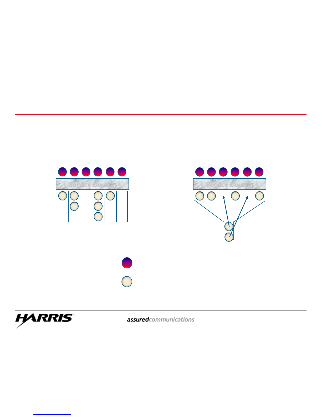
Conventional vs. Trunked
Computerized Assignment of Channels
Service Employee
Customer
Conventional
Trunked
Service Counter
Service Counter
Page 8
ECP-3405 page 9
Why Trunking?
Improves spectral efficiency
Relieves the user from managing the channel
Encourages cross agency / shared communications
Establishes communications privacy
Encourages private communications
Discourages eavesdropping by scanners
Establishes “queuing” rather than “waiting”
Enables priority use during busy times
Trunking:
Page 9

ECP-3405 page 10
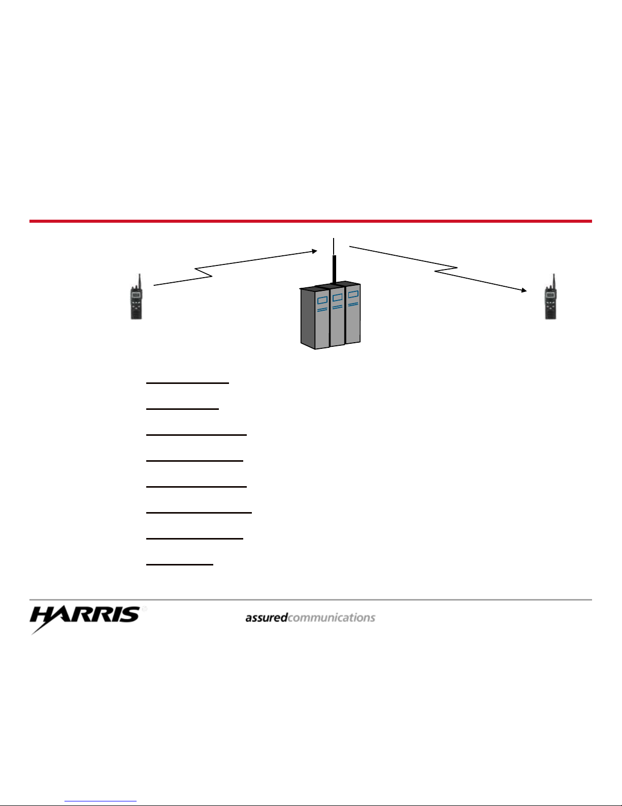
Trunked Radio System Features
Digital Control Channel
Multiple Working Channels
< 0.5 Second Access
Group & Individual Voice Calls
Logical ID (LID) for each radio
Late / Delayed Entry
Emergency Calls
Queuing with Priority
Unit Enable / Disable
Wide Area Coverage
Page 10
ECP-3405 page 11
???
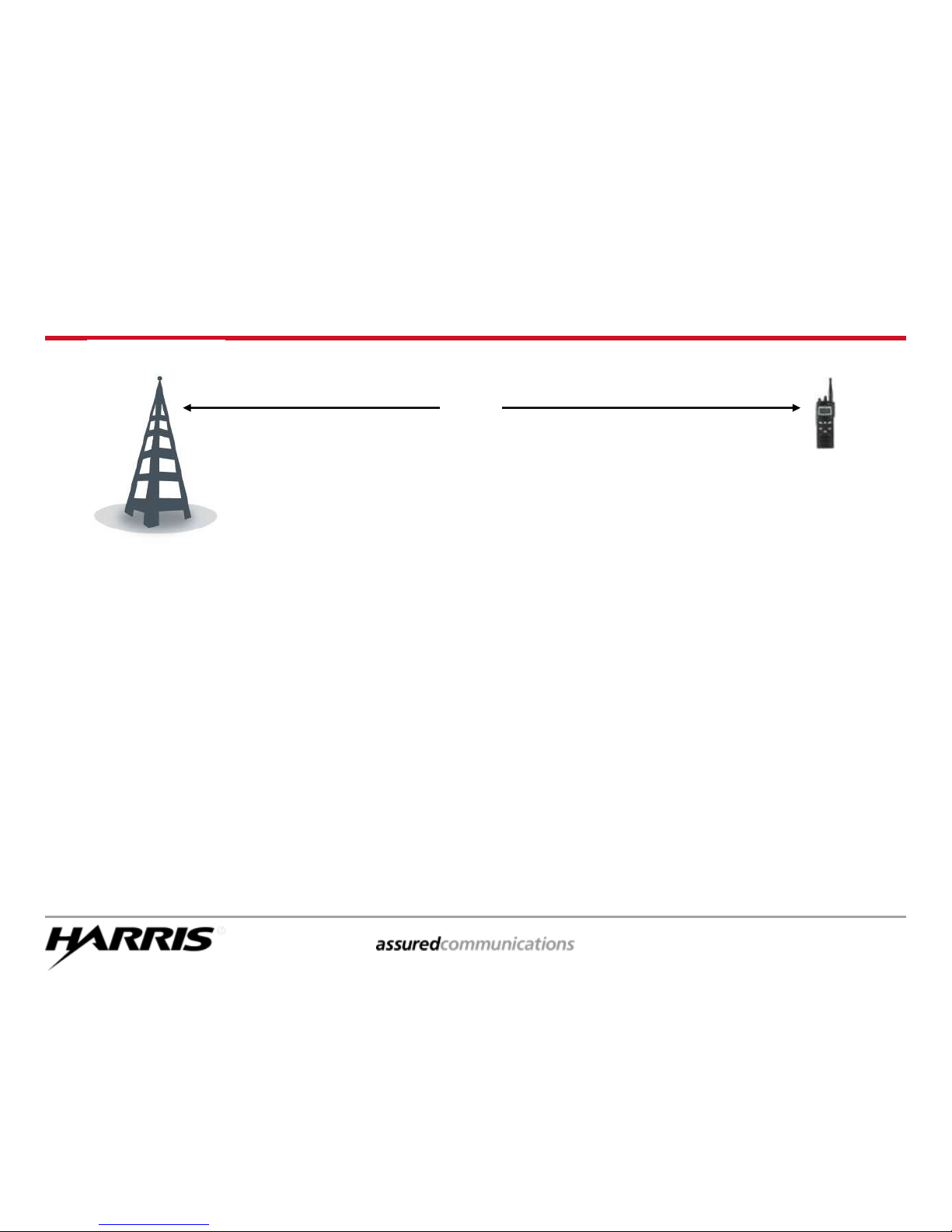
Communication Range
Many factors affect range:
– Site Location
– Urban Clutter
– Reflections / Multipath
– Ducting over Water
– Heavy vegetation
– Weather
– Frequency
Page 11
ECP-3405 page 12
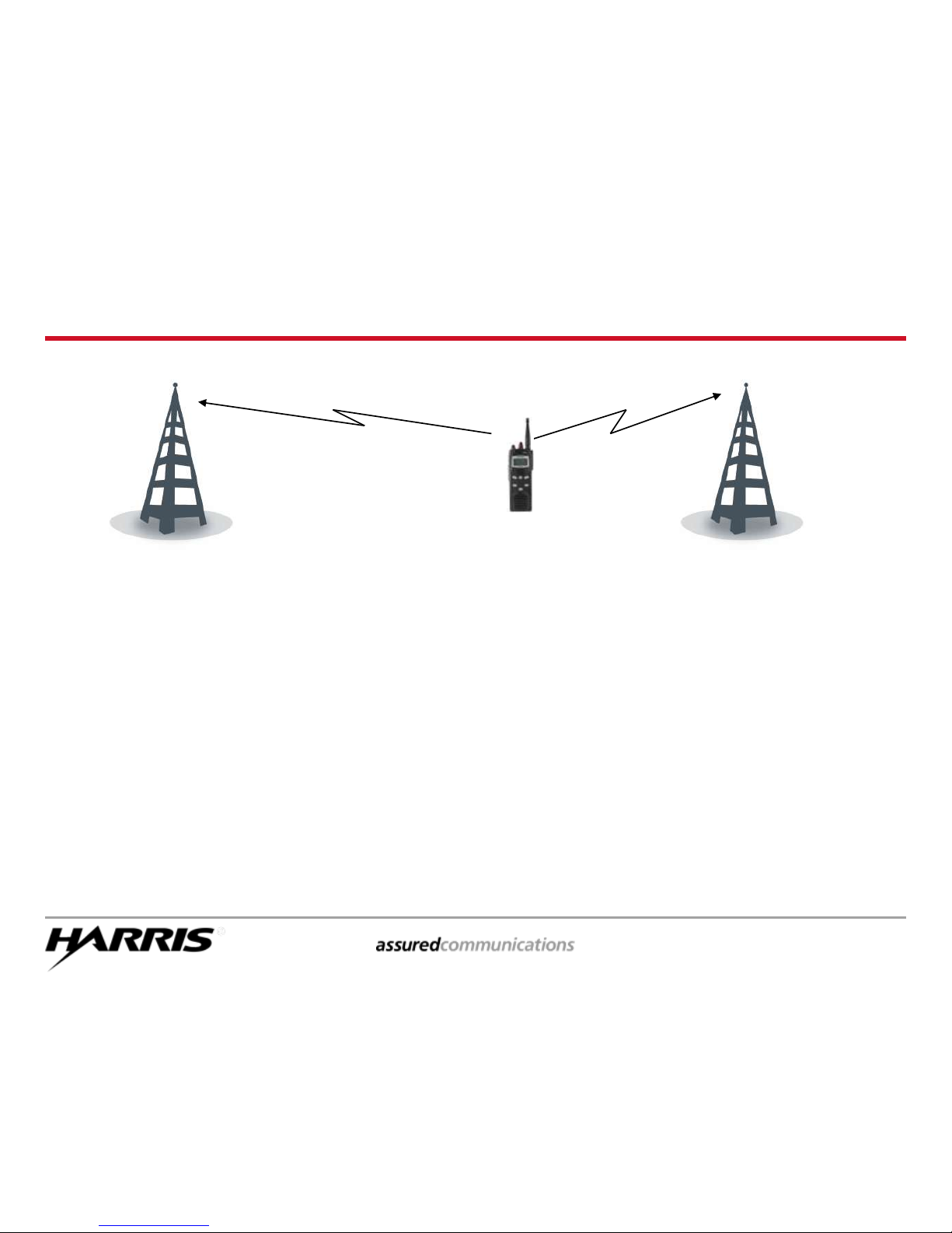
Multisite - What the Radios Do
Units inform the System of their location:
Each time the Radio is powered up
Each time a System selection is made
Each time a Group selection is made
When Radio detects a high bit error rate on the Control Channel,
Radio will look for another site (algorithm pre-programmed in Radio)
Automatically switches to the new site when the criteria is met
Site 1 Site 2
Page 12
ECP-3405 page 14
P7250 Scan Model Operation
Page 13
ECP-3405 page 15
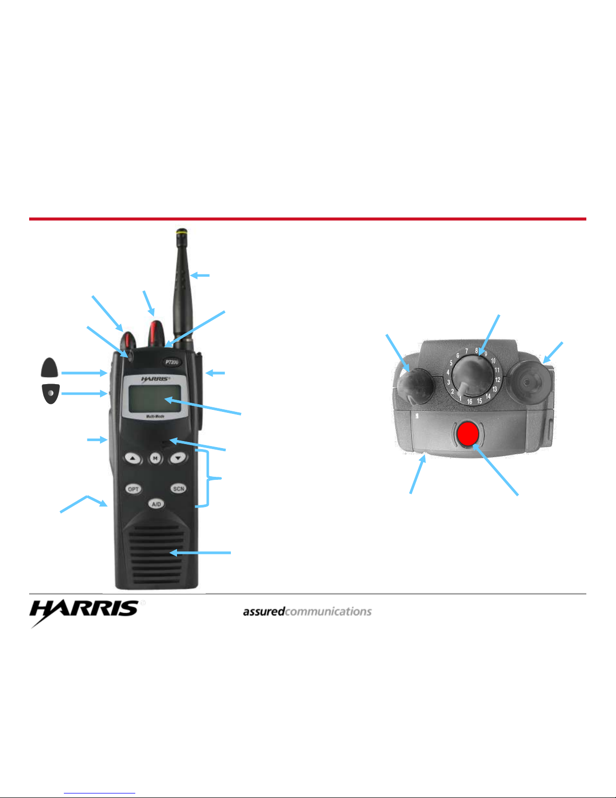
Power On/Off
& Volume Knob
Group
Select
Knob
Option Button 1
Clear Button
Push-to-Talk
(PTT)
Battery
(on Back)
Display
Universal Device
Connector “UDC”
(On Side)
Keypad
Speaker
Antenna
Emergency
Button
TX / RX
Indicator
TX / RX
Indicator
Front and Top Views
Microphone
Antenna
Emergency
Button
Group
Select
Knob
Power On/Off
& Volume
Knob
Page 14

ECP-3405 page 16
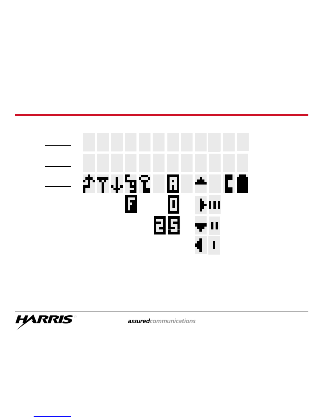
Current Talkgroup Name (example: TRNG 1)
Call Queued (QUEUED)
System Busy (SYS BUSY)
Call Denied (DENIED)
Individual Call (* INDV *)
Control Channel Scan (CC SCAN)
Wide Area Scan (WA SCAN)
Receive Emergency (* RX EMER *)
Transmit Emergency (* TX EMER *)
Current System Name (example: TRAINING)
Volume Level (VOL = 10)
Caller Identification (GR 1234)
Low Battery (LOW BATT)
‘Who Has Called’ (* WHC *)
LINE 1:
LINE 2:
LINE 3:
Radio Status Icons (see next page)
Line 1 & Line 2 Display Indicators
Page 15
ECP-3405 page 17
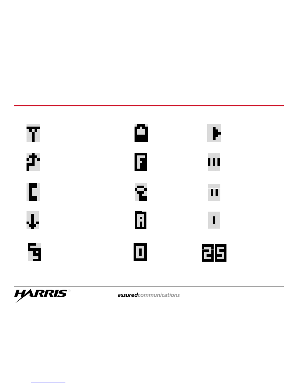
Radio Status Icons
see next page for explanations of icons
Line 3 Display Status Icons
N
I N
T
R
N
G
R A
Line 1
Line 2
Line 3
I
T
G
1
Page 16
ECP-3405 page 18
ON - transmitting or receiving
FLASHING - call queued
Radio is transmitting
Radio in special call
select/entry mode (Individual or
Telephone Interconnect)
ON - low power transmit
OFF - high power transmit
Battery level
indicator
Failsoft mode
Selected group
Encryption
enabled
SCAN enabled
(rotates clockwise)
Selected group
in scan list
Selected group
is priority-two scan
Selected group
is priority-one scan
Conventional channel
is enabled with
Channel Guard
Selected group
Analog Voice
Selected channel
Project 25 Enabled
Line 3 Icons
Selected group
Digital Voice
Page 17

ECP-3405 page 19
Keypad Function Keys
A/D
OPT
SCN
M – Accesses pre-stored menus
Acts as “Enter” key
– Scrolls through available
systems, groups, or
channels
Changes the selection for an
item within a menu list
OPT – Optional key
A/D – Adds (or deletes) talk groups
or channels from the scan
list
SCN – Turns Scan function on or off
M
Page 18

ECP-3405 page 20
Alert Tones
Call Originate short mid-pitched beep (“beep”)
Autokey short mid-pitched beep sounding after queued and an
open channel is gained (“beep”)
Call Queued high-pitched tone (“beep”) sounded when the system
places the call request in a queue
System Busy three low-pitched tones (“dut-dut-dut”), only with I-
Calls
Call Denied low-pitched tone (“bomp”) sounded when the radio is
not authorized on the selected system
Timing Out five short high-pitched warning tones (“beep..”)
followed by a low-pitched tone (“bomp”)
Key Press Alert short tone “beep”= access; low-pitched “bomp”=
denial
Low Battery short quiet mid-pitched tone (“beep”)
Missed I-Call telephone ring sounded when an incoming individual
call is not answered
Page 19

ECP-3405 page 22
Basic Radio Operation
Page 20

ECP-3405 page 23
Locking/Unlocking the Keypad
Press and release the M key and
then press and release the
upper Option button ( ) on
the side of the radio to LOCK
or UNLOCK the keypad
All front keypad keys except M
are locked
Emergency Button, PTT, and both
knobs function normally
KEY LOCK
BCK LGHT
CONTRAST
Upper
Option
Button
M
Key
Page 21

ECP-3405 page 24
Changing Talk Groups
Turn the GROUP SELECT
knob to select a group
Group names appear on
Line 2 of the display
Group
Select
Knob
Group
Names
Displayed
Page 22

ECP-3405 page 25
Making a Group Call
Turn on the radio
Select the group you want to
reach
Group names appear on Line
2 of the display
Push-to-Talk (PTT)
Indicator will light red while
transmitting (orange if
transmitting in encrypted
mode)
Group
Select
Knob
Power
On/Off
Volume
Knob
Indicator
Light
PTT
Group
Names
Displayed
Page 23

ECP-3405 page 26
Receiving a Group Call
The caller’s Radio ID or alias
appears on Line 1 (ex. 1234)
Group that is transmitting
appears on Line 2
Indicator will light green while
receiving
If in SCAN and you want to talk
to the caller, change to the
group that appeared in the
display
PTT to respond
Group
Select
Knob
PTT
Indicator
Light
Group
Name
Displayed
Caller’s ID
or Alias
Displayed
Page 24

ECP-3405 page 27
Changing Systems
Use the keys to select
another system
System names appear on Line
1 of the display
Keys
System
Names
Displayed
Page 25

ECP-3405 page 28
Adjust Display Backlight Brightness
KEY LOCK
BCK LGHT
CONTRAST
Keys
M
Key
Press the M key to access the menu
Use either of the arrow keys
to position the “ > ” cursor
at BCK LGHT
Press the M key to select the
Backlight menu
Use the arrow keys to adjust
the brightness level of the display
backlight from “Off” up to 6
Press the M key to select the new
setting
> Cursor
Pointing to
BCK LGHT
Page 26

ECP-3405 page 29
Adjust Display Contrast
Press M to enter the Menu mode
Use the keys to find and
select CONTRAST
Press M a second time
CNTRST = 1, 2, 3, or 4 will appear
in the display with the current
setting
Use the keys to change
the contrast level
Press M a third time to store the
change
KEY LOCK
BCK LGHT
CONTRAST
Keys
M
Key
> Cursor
Pointing to
CONTRAST
Page 27

ECP-3405 page 30
Changing the Power Level
– page 1
CONTRAST
REVISION
TX POWER
Keys
M
Key
If enabled, the transmit power level of
the radio can be adjusted
Press the M key to access the menu
Use either of the arrow keys
to position the “ > ” cursor
to TX POWER
Press the M key to toggle between
High and Low power
POWER=HIGH or POWER=LOW
will appear momentarily in the
display
> Cursor
Pointing to
TX POWER
Page 28

ECP-3405 page 31
Changing the Power Level
– page 2
If enabled, the transmit power level
of the radio can be adjusted
simply by pressing the pre-
programmed “Option” button on
the side of the radio
Press the upper option button
on the side of the radio to
toggle between High and Low
power
POWER=HIGH or POWER=LOW
will appear momentarily in the
display
Upper
Option
Button
POWER=HIGH
POWER=HIGH
or
POWER=LOW
Appears
Briefly
Page 29

ECP-3405 page 32
Emergencies
Page 30

ECP-3405 page 33
Top View
Declaring an Emergency
PTT
*TXEMER*
Displayed
Emergency
Button
Emergency
Button
Indicator
Light
Press and hold the red EMERGENCY
button on the top of the radio for a
preprogrammed amount of time
* TXEMER * appears in display and will
remain until the emergency is
cleared
The microphone will be active for a
programmed length of time, but the
PTT can be depressed to extend the
time needed to report the
emergency circumstances
Page 31

ECP-3405 page 34
Receiving an Emergency
Indicator
Light
PTT
*RXEMER *
Displayed
* RXEMER * appears in display and
will remain until the emergency is
cleared
The microphone will be deactivated
for a programmed length of time
(while the unit that declared the
emergency is transmitting) but the
radio will function normally after
the initial transmission is
complete
PTT to respond if appropriate
Page 32

ECP-3405 page 35
Clearing an Emergency
Press and hold the lower option
(CLEAR) button ( ) on the
side of the radio
Simultaneously press and hold
the EMERGENCY button until
*TXEMER* stops flashing in
the display
NOTE –
Only certain radios and specific radio
operators will be authorized to clear
emergencies (the portable radio must be
pre-configured and the operator must be
specifically authorized in order to clear
emergencies)
Emergency
Button
Lower
Option
(CLEAR)
Button
Page 33

ECP-3405 page 36
Call Scanning
Group 1
Group 2
?
Page 34

ECP-3405 page 37
Group Call Scanning
The radio is able to monitor multiple groups, but the radio can only receive
one group at a time
The radio can scan only those groups on a “Scan List”
This list can be programmed by the user, or
The list may be directly programmed into the radio by the Network Administrator
Turning the Scan function On or Off can be:
Fixed in programming by the Network Administrator, or
Controlled by the radio user
The radio can have up to two “Priority Talk Groups” designated
Priority 1 Talk Group
Priority 2 Talk Group
Priority Talk Groups can be assigned by the radio user, or they might be
fixed in the programming by the Network Administrator
The radio will be extracted from listening to a scanned call if a call with a
higher priority is received
Page 35

ECP-3405 page 38
Turning SCAN On/Off
Press the SCN key to turn on
the Scan function
The icon rotates clockwise
to indicate the radio is
scanning.
Press SCN again to turn off
the Scan function and the
icon will disappear.
SCN
Key
Scan Icon
Rotates
Page 36

ECP-3405 page 39
Establishing a Scan List
If necessary, turn Scan off by
pressing the SCN key
The indicator will disappear from
the display
To Scan, you must have a Scan List,
and to create or edit your Scan List,
you must have Scan turned off
SCN
Key
Scan Icon
Disappears
Page 37

ECP-3405 page 40
Adding Groups to the Scan List
Turn the Group Select knob to the
group you wish to add to your
Scan List
Press the A/D key once to add the
group to the Scan List
III will appear in the display
indicating the addition of the
group to the Scan List
Turn to the next group and repeat
the process to add that group to
your Scan List
NOTE – If “FIXD LST” appears instead of the 3-bar
icon, a fixed scan list has been programmed
into the radio, and you will not be able to
change it
III
Group
Select
Knob
A/D
Key
III Bars
Displayed
Page 38

ECP-3405 page 41
Creating a Priority 2 Talk Group
Turn the Group Select knob to the
group you wish to make your
Priority 2 for scanning
Press the A/D key once to add the
group to the Scan List
III bars appear in the display
Press A/D again to prioritize the
group to Priority 2
II bars appear in the display to
indicate this is the Priority 2
group
NOTE – You can only have one “Priority 2” talk group
in your scan list – changing another talk group to
“Priority 2” will cause the previously-designated
talk group to revert to a non-priority scanned
group ( III )
II
Group
Select
Knob
A/D
Key
II Bars
Displayed
Page 39

ECP-3405 page 42
Creating a Priority 1 Talk Group
I
Group
Select
Knob
A/D
Key
I Bar
Displayed
Turn the Group Select knob to the
group you wish to make your
Priority 1 for scanning
Press the A/D key once to add the
group to the Scan List ( III )
Press A/D again to prioritize the
group to Priority 2 ( II )
Press A/D again to prioritize the group
to Priority 1
I bar is displayed to indicate this is the
Priority 1 group
NOTE – You can only have one “Priority 1” talk group
in your scan list
Page 40

ECP-3405 page 43
Deleting Talk Groups from the Scan List
Turn the Group Select knob to the
group you wish to delete from
your Scan List
Press the A/D key until none of the
scan priority bars ( III, II, or I )
are displayed
The talk group will no longer be
scanned until you replace the
group in your Scan List
Group
Select
Knob
A/D
Key
III, II, or I
Priority Bars
Disappear
III = in scan list – no priority
II = in scan list – Priority 2
I = in scan list – Priority 1
no bars = not in scan list
Page 41

ECP-3405 page 44
Special Calls
Individual Calls & Telephone Calls
Page 42

ECP-3405 page 45
Sending an Individual Call
– page 1
REVISION
TX POWER
INDV CALL
Keys
M
Key
If this feature is enabled, the radio can
initiate individual radio-to-radio
calls to another radio
Press the M key to access the menu
Use either of the arrow keys
to position the “ > ” cursor
to INDV CALL
Press the M key to select this feature
A list of available radios that can be
called individually will be displayed
> Cursor
Pointing to
INDV CALL
Page 43

ECP-3405 page 46
Sending an Individual Call
– page 2
Note: While in the individual call mode,
you will miss all talk group calls
12001019
12001022
12001023
Keys
Lower
Option
(CLEAR)
Button
PTT
Use either of the arrow keys
to position the “ > ” cursor beside
the ID number (User ID or Logical ID)
of the radio to be called
PTT to send the call
The Special Call icon will appear
while the individual call is in
progress
To end the individual call, press
the lower option button
on the side of the radio
Page 44

ECP-3405 page 47
Receiving an Individual Call
Line 1 shows the alias of the
caller or the LID of the unit
sending the message
Line 2 shows * INDV *
The Special Call icon
appears on Line 3
To answer: PTT
(Only the caller can hear you)
To end the call, press the
lower option button
on the side of the radio
Note: While in the individual call mode,
you will miss all talk group calls
Lower
Option
(CLEAR)
Button
PTT
*INDV *
Displayed
Caller’s ID
or Alias
Displayed
Special
Call Icon
Displayed
Page 45

ECP-3405 page 48
Missing an Individual Call
Line 1 will display * WHC *
and the radio will begin
ringing
To stop the ringing, press the
lower option (CLEAR)
button
If an Individual Call is not answered:
* WHC *
Displayed
Lower
Option
(CLEAR)
Button
Page 46

ECP-3405 page 49
Returning a Missed Individual Call
Keys
Caller’s LID
or Alias
Displayed
“Who Has
Called”
Index Number
Displayed
Press the M key to access the menu
Use either of the arrow keys
to position the “ > ” cursor
to INDV CALL
Press the M key to select this option
Line 2 shows the WHCI (Who Has
Called Index) entry number
Line 1 shows the LID, User ID or alias
of the unit that tried to call
Use the arrow keys to scroll
through other radio numbers if
desired
PTT to initiate the return call
PTT
Page 47

ECP-3405 page 50
Telephone Interconnect Calls
In order to connect to a telephone scan, your system must
be equipped with a Public Service Telephone Network
(PSTN) interface device of some type
You will receive specific instructions regarding disclosure
of the direct-dial-in capabilities of your telephone interface
system as they apply to your radio system utilization and
to your organization
Page 48

ECP-3405 page 51
Sending a Telephone Call
– page 1
APPLICTN
PHN CALL
KEY LOCK
Keys
Lower
Option
(CLEAR)
Button
PTT
If this feature is enabled, the radio can
make a telephone call through a
PSTN interchange to a telephone
Press the M key to access the menu
Use either of the arrow keys
to position the “ > ” cursor
to PHN CALL
Press the M key to select this feature
A list of available telephone numbers
that have been pre-programmed into
the radio will be displayed
> Cursor
Pointing to
PHN CALL
Page 49

ECP-3405 page 52
Sending a Telephone Call
– page 2
Note: While in the phone call mode, you
will miss all talk group calls
4344559454
4344559458
4344559521
Keys
Lower
Option
(CLEAR)
Button
PTT
Use either of the arrow keys
to position the “ > ” cursor beside
the telephone number to be called
PTT to initiate the call
The special call icon will appear
and will remain displayed until the
call is concluded
To end the telephone call, press the
lower option button
on the side of the radio
Page 50

ECP-3405 page 53
Receiving a Telephone Call
Note: While in the phone call mode, you
will miss all talk group calls
Lower
Option
(CLEAR)
Button
PTT
The telephone number of the
network PSTN interface will be
displayed on the top line
The second line will display the
“PHONE”
To respond, press the PTT (only the
telephone caller can hear you)
The special call icon will appear
To end the call, press the
lower OPTION button on
the side of the radio
5551234
* PHONE *
Page 51

ECP-3405 page 54
Special Licensed Features
Status & Message Alert Calls
Request-to-Talk Function
Page 52

ECP-3405 page 55
Status & Message Operations
STATUS operation allows a pre-programmed status condition to
be transmitted to a P25 trunked tower site
MESSAGE operation allows a pre-programmed text message to
be transmitted to a P25 trunked tower site
Each STATUS and MESSAGE is assigned an ID that is cross-
referenced to a determined condition (ie., Off Duty, In Service,
Transporting, or some similar message)
The messages are routed from the tower site to a specific
dispatch console (or to several specific consoles) that have been
pre-designated to receive that particular message (based on the
assigned ID number)
Each STATUS condition message and each MESSAGE text is pre-
programmed by the system administrator – individual radio
operators cannot enter their own messages as “text” entries
nor can they choose which console(s) receive the message
Page 53

ECP-3405 page 56
Status Message Operation
TX POWER
> STATUS
MESSAGE
Press the M key to access the menu
Use either of the arrow keys
to position the “ > ” cursor
to STATUS
Press the M key to select STATUS
operation
Use either of the arrow keys
to position the “ > ” cursor
to the status message to be sent
(up to 10 different status messages
can be pre-programmed)
Press the M key again to send the
message (or to save it in the radio’s
memory where it can be retrieved by
the site later)
Keys
M
Key
> Cursor
Pointing to
STATUS
Page 54

ECP-3405 page 57
RTT Message Operation
TX POWER
STATUS
> MESSAGE
Press the M key to access the menu
Use either of the arrow keys
to position the “ > ” cursor
to MESSAGE
Press the M key to select MESSAGE
operation
Use either of the arrow keys
to position the “ > ” cursor
to the status message to be sent
(up to 10 different messages can be
pre-programmed)
Press the M key again to send the
message (or to save it in the radio’s
memory where it can be retrieved by
the site later)
Keys
M
Key
> Cursor
Pointing to
MESSAGE
Page 55

ECP-3405 page 58
Request-to-Talk Function
PTT
Press the OPT key to send a
“Request-to-Talk” notification to
the dispatcher
When the dispatcher acknowledges
your request, press the PTT and
transmit normally
OPT
Key
Note – Each customer may have a
different method to signal RTT
(RTT-Normal, RTT-Priority, or RTT-
Cancel), which may result in certain
keypad keys being mapped to
perform specific functions.
Always verify RTT operation &
methods with your management.
Page 56

ECP-3405 page 59
Radio Care
Troubleshooting Tips &
Battery Replacement
Page 57

ECP-3405 page 60
Troubleshooting Tips
Issue What do you do?
Any talk group or system configuration
or structuring (fleet mapping) issue, or
any RF coverage issues
Contact your management
to report the issue
Any physical radio equipment issues
Contact your management
to report the issue
Any failure of the radio or any error
code appears in the display that is not
explained
Contact your management
to report the issue
Slight delay in audio
All digital communications
have a slight delay in audio
Only noticeable when radios
are in very close proximity
Page 58

ECP-3405 page 61
RELEASE
BUTTON
LIFT UP
& AWAY
POWER
ON/OFF
Changing the Battery
Before changing the battery, turn the radio off
Press the battery release button on the bottom of
the battery
Lift the bottom of the battery pack up and away
until it separates from the radio
Insert the top of the new battery onto the radio
and press down until it clicks in place
Page 59

ECP-3405 page 62
Notes
Page 60

RF Communication Division | 221 Jefferson Ridge Parkway | Lynchburg, VA USA 24501
Tel: 800-528-7711 www.harris.com
Copyright© 2012 Harris Corporation
Harris is a registered trademark of Harris Corporation.
 Loading...