

Page 1

Operator’s Manual
MM-008212-001
Rev. L, July 2015
P5300 Series
Portable Radio
Page 2

MM-008212-001, Rev. L
REV
DATE
REASON FOR REVISION
Copyright © 2007-2011, 2013-2015 Harris Corporation.
A Jul/07 Added Lithium Ion battery pack tamper warning.
B Apr/08 Added 800 MHz SAR information for P5300 series portable radios. Added Type 99 Operation information.
C Oct/08 Updated user interface and accessories.
D Aug/09 Reformat to change to the Harris corporate identity. Include, modify, and make consistent any language for Dual
E Mar/10 Remove the reference to BT-023406-006.
F Apr/11 Updated for OTP R17; consolidated ECP operation into one section.
G May/13 Incorporated addendums. Added stealth mode and PIN entry (ECP R16A). Added Audio Playback. Added
H Sep/13 Updated options and accessories. Updated cleaning procedure.
J Oct/14 Added CE information. Added Radio TextLink operation, view GPS information, and Control and Status services.
K Apr/15 Updated for XGP R5A.
L Jul/15 Added HAZLOC info. Added additional warnings to Section 3.1.5.
Harris Corporation, Public Safety and Professional Communications (PSPC) Business continually evaluates its technical publications for
completeness, technical accuracy, and organization. You can assist in this process by submitting your comments and suggestions to the following:
Harris Corporation fax your comments to: 1-434-455-6851
PSPC Business or
Technical Publications e-mail us at: PSPC_TechPubs@harris.com
221 Jefferson Ridge Parkway
Lynchburg, VA 24501
The software contained in this device is copyrighted by Harris Corporation Unpublished rights are reserved under the copyright laws of the United
States.
This device is made under license under one or more of the following US patents: 4,590,473; 4,636,791; 5,148,482; 5,185,796; 5,271,017;
5,377,229; 4,716,407; 4,972,460; 5,502,767; 5,146,497; 5,164,986; 5,185,795; 5,226,084; 5,247,579; ; 5,491,772; 5,517,511; 5,630,011; 5,649,050;
5,701,390; 5,715,365; 5,754,974; 5,826,222; 5,870,405; 6,161,089; and 6,199,037 B1. DVSI claims certain rights, including patent rights under
aforementioned U.S. patents, and under other U.S. and foreign patents and patents pending. Any use of this software or technology requires a
separate written license from DVSI.
Harris Corporation, EDACS, and OpenSky are registered trademarks and ProScan, Failsoft, and TECHNOLOGY TO CONNECT, INFORM AND
PROTECT are trademarks of Harris Corporation.
RBRC and 1-800-8-BATTERY are registered trademarks of Rechargeable Battery Recycling Corporation.
AMBE is a registered trademark and IMBE, AMBE+, and AMBE+2 are trademarks of Digital Voice Systems, Inc.
All other product and brand names are trademarks, registered trademarks, or service marks of their respective holders.
The material contained herein is subject to U.S. export approval. No export or re-export is permitted without written approval from the U.S.
Government. Rated: EAR99; in accordance with U.S. Dept. of Commerce regulations 15CFR774, Export Administration Regulations.
Information and descriptions contained herein are the property of Harris Corporation. Such information and descriptions may not be copied or
reproduced by any means, or disseminated or distributed without the express prior written permission of Harris Corporation,
Jefferson Ridge Parkway, Lynchburg, VA 24501.
Position A/B Switch functionality.
OpenSky A/B switch functionality. Updates to OpenSky operation. Added cleaning instructions. Updated Options
and Accessories. Updated warranty.
Updated accessories and Data TX/RX displayed indicators. Added Voice Annunciation.
ACKNOWLEDGEMENTS
CREDITS!
NOTICE!
PSPC Business, 221
This product conforms to the European Union WEEE Directive 2012/19/EU. Do not dispose of this product in a public landfill. Take
it to a recycling center at the end of its life.
Harris products comply with the Restriction of the Use of Certain Hazardous Substances in Electrical and Electronic Equipment
(RoHS) Directive.
The voice coding technology embodied in this product is protected by intellectual property rights including patent rights, copyrights, and trade
secrets of Digital Voice Systems, Inc. The user of this technology is explicitly prohibited from attempting to decompile, reverse engineer, or
disassemble the Object Code, or in any other way convert the Object Code into human-readable form.
Repairs to this equipment should be made only by an authorized service technician or facility designated by the supplier. Any repairs, alterations,
or substitution of recommended parts made by the user to this equipment not approved by the manufacturer could void the user’s authority to
operate the equipment in addition to the manufacturer’s warranty.
This manual is published by Harris Corporation, without any warranty. Improvements and changes to this manual necessitated by typographical errors, inaccuracies of current
information, or improvements to programs and/or equipment, may be made by Harris Corporation, at any time and without notice. Such changes will be incorporated into new
editions of this manual. No part of this manual may be reproduced or transmitted in any form or by any means, electronic or mechanical, including photocopying and recording, for
any purpose, without the express written permission of Harris Corporation.
2
Page 3
MM-008212-001, Rev. L
This device is a RF transceiver intended for land mobile radio applications. The device may have use restrictions, which require that the
national authority be contacted for any system licensing requirements, frequency use, allowable power level, etc.
3
Page 4

MM-008212-001, Rev. L
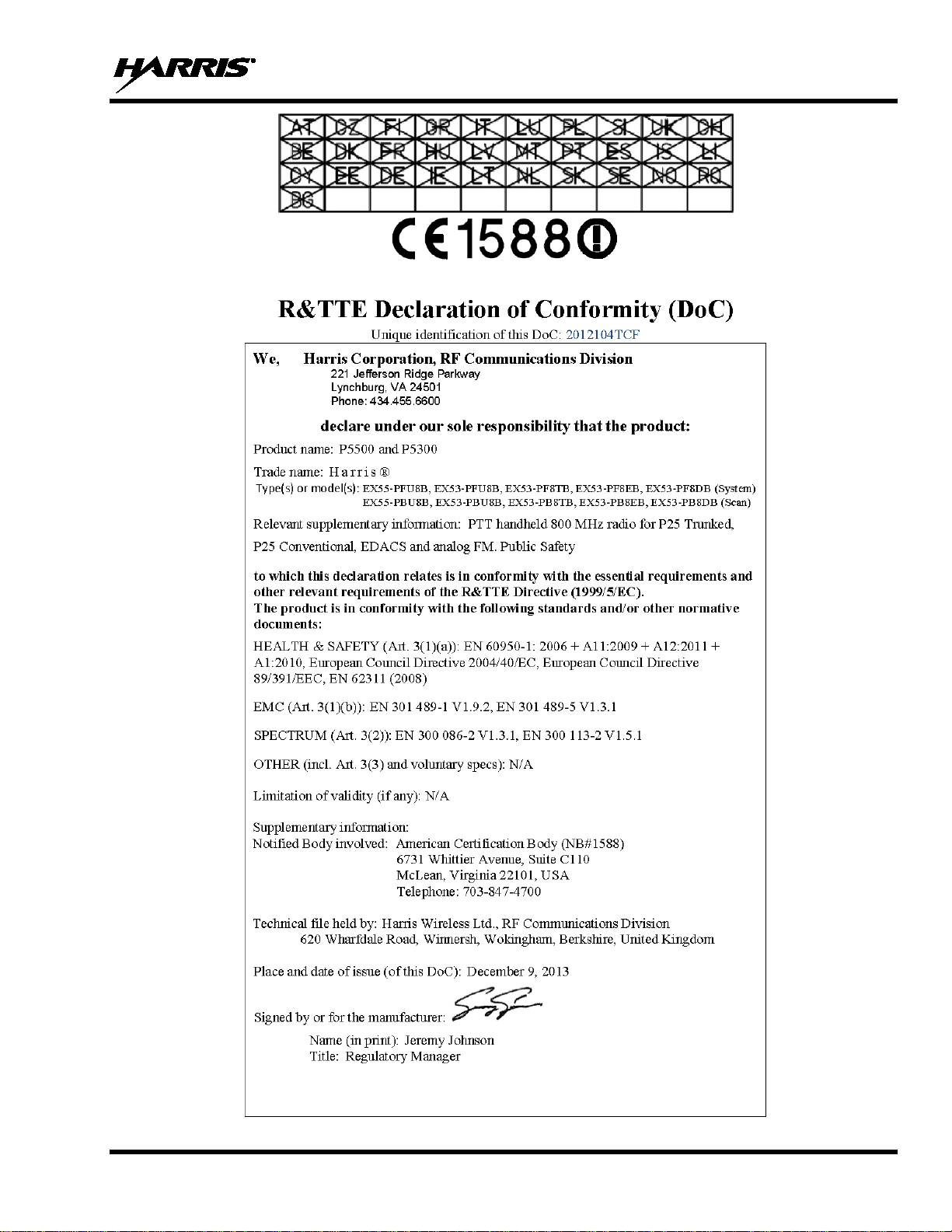
Česky
[Czech]
Harris Corporation tímto prohlašuje, že tento 800 (806-824, 851-870 MHz) je ve shodě se
základními požadavky a dalšími příslušnými ustanoveními směrnice 1999/5/ES.
Dansk
[Danish]
Undertegnede Harris Corporation erklærer herved, at følgende udstyr 800 (806-824, 851-870
MHz) overholder de væsentlige krav og øvrige relevante krav i di rektiv 1999/5/EF.
Deutsch
Hiermit erklärt Harris Corporation, dass sich das Gerät 800 (806-824, 851-870 MHz) in
Bestimmungen der Richtlinie 1999/5/EG befindet.
Eesti
Käesolevaga kinnitab Harris Corporation seadme 800 (806-824, 851-870 MHz) vastavust
sätetele.
Hereby, Harris Corporation, declares that this 800 (806-824, 851-870 MHz) is in compli ance
with the essential requirements and other relevant provisions of Directive 1999/5/EC.
Español
Por medio de la presente Harris Corporation declara que el 800 (806-824, 851-870 MHz)
de la Directiva 1999/5/CE.
ΜΕ ΤΗΝ ΠΑΡΟΥΣΑ Harris Corporation ΔΗΛΩΝΕΙ ΟΤΙ 800 (806-824, 851-870 MHz)
ΔΙΑΤΑΞΕΙΣ ΤΗΣ ΟΔΗΓΙΑΣ 1999/5/ΕΚ.
Par la présente Harris Corporation déclare que l'ap pareil 800 (806-824, 851-870 MHz) est
1999/5/CE.
Italiano
Con la presente Harris Corporation dichiara che questo 800 (806-824, 851-870 MHz) è
1999/5/CE.
Latviski
[Latvian]
Ar šo Harris Corporation deklarē, ka 800 (806-824, 851-870 MHz) atbilst Direktīvas 1999/5/EK
būtiskajām prasībām un citiem ar to saistītajiem noteikumiem.
Lietuvių
[Lithuanian]
Šiuo Harris Corporation deklaruoja, kad šis 800 (806-824, 851-870 MHz) atitinka esminius
reikalavimus ir kitas 1999/5/EB Direktyvos nuostatas.
[Dutch]
Hierbij verklaart Harris Corporation dat het toestel 800 (806-824, 851-870 MHz) in
1999/5/EG.
[Maltese]
Hawnhekk, Harris Corporation, jiddikjara li dan 800 (806-824, 851-870 MHz) jikkonforma mal[Hungarian]
Alulírott, Harris Corporation nyilatkozom, hogy a 800 ( 806-824, 851-870 MHz) megfelel a
[Polish]
Niniejszym Harris Corporation oświadcza, że 800 (806-824, 851-870 MHz) jest zgodny z
[German]
[Estonian]
English
[Spanish]
Ελληνική
[Greek]
Français
[French]
[Italian]
Übereinstimmung mit den grundlegenden Anford erungen und den übrigen einschlägigen
direktiivi 1999/5/EÜ põhinõuetele ja nimetatud direktiivist tulenevatele teistele asjakohastel e
cumple con los requisitos esenciales y cualesquiera otras disposiciones aplicables o exigibles
ΣΥΜΜΟΡΦΩΝΕΤΑΙ ΠΡΟΣ ΤΙΣ ΟΥΣΙΩΔΕΙΣ ΑΠΑΙΤΗΣΕΙΣ ΚΑΙ ΤΙΣ ΛΟΙΠΕΣ ΣΧΕΤΙΚΕΣ
conforme aux exigences essentielles et aux autres dispositions pertinentes de la directive
conforme ai requisiti essenziali ed alle altre disposizioni pertinenti stabilite dalla direttiva
Nederlands
Malti
Magyar
Polski
overeenstemming is met de essentiële eisen en de a ndere relevante bepalingen van richtlijn
ħtiġijiet essenzjali u ma provvedimenti oħrajn relevanti li hemm fid-Dirrettiva 1999/5/ EC.
vonatkozó alapvetõ követelményeknek és az 1999/5/EC irányelv egyéb elõírásainak.
zasadniczymi wymogami oraz pozostałymi stosownymi postanowieniami Dyrektywy 1999/5/EC.
4
Page 5
MM-008212-001, Rev. L
Português
[Portuguese]
Harris Corporation declara que este 800 (806-824, 851-870 MHz) está conforme com os
requisitos essenciais e outras disposições da Directiva 1999/5/CE.
Slovensko
[Slovenian]
Harris Corporation izjavlja, da je ta 800 (806-824, 851-870 MHz) v skladu z bistvenimi
zahtevami in ostalimi relevantnimi določili direktive 1999/5/ES.
Slovensky
[Slovak]
Harris Corporation týmto vyhlasuje, že 800 (80 6-824, 851-870 MHz) spĺňa základné
požiadavky a všetky príslušné ustanovenia S m ernice 1999/5/ES.
Suomi
Harris Corporation vakuuttaa täten että 800 (8 06-824, 851-870 MHz) tyyppinen laite on
mukainen.
Svenska
Härmed intygar Harris Corporation att denna 800 (806-824, 851-870 MHz) står I
framgår av direktiv 1999/5/EG.
Íslenska
[Icelandic]
Hér með lýsir Harris Corporation yfir því að 800 (806-824, 851-870 MHz) er í samræmi við
grunnkröfur og aðrar kröfur, sem gerðar eru í ti l skip un 1999/5/EC.
Norsk
[Norwegian]
Harris Corporation erklærer herved at utstyret 800 (806-824, 851-870 MHz) er i samsvar med
de grunnleggende krav og øvrige relevante krav i direktiv 1999/5/EF.
[Finnish]
[Swedish]
direktiivin 1999/5/EY oleellisten vaatimusten ja sit ä koskevien direktiivin muiden ehtojen
överensstämmelse med de väsentliga egenskap skrav och övriga relevanta bestämmelser som
5
Page 6

MM-008212-001, Rev. L
Page
9.5 LOG OFF THE NETWORK ...................................................................................................... 31
TABLE OF CONTENTS
1 SAFETY CONVENTIONS .................................................................................................................. 12
2 SAFETY TRAINING INFORMATION ............................................................................................ 13
2.1 RF EXPOSURE GUIDELINES ................................................................................................. 13
2.2 ELECTROMAGNETIC INTERFERENCE/COMPATIBILITY ............................................... 14
3 OPERATING TIPS .............................................................................................................................. 15
3.1 EFFICIENT RADIO OPERATION ........................................................................................... 15
3.1.1 Antenna Care and Replacement ..................................................................................... 15
3.1.2 Electronic Devices ......................................................................................................... 15
3.1.3 Aircraft ........................................................................................................................... 16
3.1.4 Electric Blasting Caps.................................................................................................... 16
3.1.5 Potentially Explosive Atmospheres ............................................................................... 16
4 CLEANING ........................................................................................................................................... 17
5 BATTERIES ......................................................................................................................................... 18
5.1 CONDITIONING BATTERY PACKS ...................................................................................... 18
5.1.1 Conditioning NiMH Battery Packs ................................................................................ 18
5.1.2 Conditioning NiCd Battery Packs ................................................................................. 18
5.1.3 Storing Li-Ion Battery Packs ......................................................................................... 19
5.1.4 Additional Information .................................................................................................. 19
5.2 CHARGING BATTERY PACKS .............................................................................................. 19
5.3 BATTERY PACK USAGE ........................................................................................................ 19
5.4 CHANGING THE BATTERY PACK ....................................................................................... 20
5.4.1 Removing the Battery Pack ........................................................................................... 20
5.4.2 Attaching the Battery Pack ............................................................................................ 21
5.5 BATTERY DISPOSAL .............................................................................................................. 21
6 INTRODUCTION ................................................................................................................................ 22
7 OPTIONS AND ACCESSORIES........................................................................................................ 23
8 CHANGE OPERATING MODE ........................................................................................................ 25
8.1 CHANGE FROM OTP MODE .................................................................................................. 25
8.2 CHANGE TO OTP MODE ........................................................................................................ 25
9 OPENSKY OPERATION .................................................................................................................... 26
9.1 CONTROLS ............................................................................................................................... 26
9.1.1 Buttons, Knobs, and Switch ........................................................................................... 26
9.1.2 Keypad ........................................................................................................................... 28
9.2 DISPLAY ................................................................................................................................... 29
9.3 TRI-COLOR LED ...................................................................................................................... 30
9.4 LOG IN TO THE NETWORK ................................................................................................... 30
6
Page 7

MM-008212-001, Rev. L
Page
9.21.4 Rejecting a Selective Call .............................................................................................. 47
TABLE OF CONTENTS
9.6 PERSONALITY ......................................................................................................................... 31
9.6.1 Profiles ........................................................................................................................... 31
9.6.2 Talk Groups ................................................................................................................... 32
9.7 OPENSKY DISPLAY OVERVIEW .......................................................................................... 32
9.7.1 Display’s Top Line ........................................................................................................ 32
9.7.2 Display’s Second Line ................................................................................................... 32
9.7.3 Dwell Display ................................................................................................................ 32
9.8 ALERT TONES ......................................................................................................................... 33
9.9 ERROR MESSAGES ................................................................................................................. 34
9.10 BASIC MENU STRUCTURE ................................................................................................... 36
9.11 KEYPAD .................................................................................................................................... 38
9.11.1 Keypad Function Commands (P5370 Only) .................................................................. 38
9.11.2 Quick Keys (P5370 Only) ............................................................................................. 39
9.11.3 DTMF Overdial ............................................................................................................. 39
9.11.4 Lock/Unlock the Keypad ............................................................................................... 39
9.11.5 Dual-Tone Multi-Frequency (P5370 only) .................................................................... 40
9.12 CHANGING THE ACTIVE PROFILE ..................................................................................... 40
9.13 CHANGING THE SELECTED TALK GROUP ....................................................................... 40
9.14 ADJUSTING DISPLAY AND BUTTON BACKLIGHT BRIGHTNESS ................................ 40
9.15 STEALTH MODE ...................................................................................................................... 40
9.15.1 Enabling Stealth Mode .................................................................................................. 40
9.15.2 Disabling Stealth Mode ................................................................................................. 40
9.16 ADJUSTING SIDE TONE AUDIO LEVEL ............................................................................. 41
9.17 RECEIVING AND TRANSMITTING VOICE CALLS ........................................................... 41
9.17.1 Receiving a Voice Call .................................................................................................. 41
9.17.2 Transmitting a Voice Call .............................................................................................. 42
9.18 ADJUSTING AUDIO TREBLE LEVEL ................................................................................... 42
9.19 TALK GROUP LOCK OUT ...................................................................................................... 42
9.19.1 Lock Out a Talk Group .................................................................................................. 43
9.19.2 Unlock a Talk Group ..................................................................................................... 43
9.20 SCANNING ................................................................................................................................ 43
9.20.1 Selecting Scan Modes .................................................................................................... 43
9.20.2 Change Active Scan Mode ............................................................................................ 44
9.20.3 Scanning Priority ........................................................................................................... 44
9.20.4 Scan Mode A/B Switch ................................................................................................. 45
9.20.5 Scan Mode Quick Key (P5470 Only) ............................................................................ 45
9.21 MAKING SELECTIVE CAL
LS ................................................................................................ 45
9.21.1 Manually Dialing a Selective Call (P5370 Only) .......................................................... 46
9.21.2 Selective Call Using Speed Dial .................................................................................... 47
9.21.3 Accepting a Selective Call ............................................................................................. 47
7
Page 8

MM-008212-001, Rev. L
Page
9.21.5 Terminating a Selective Call ......................................................................................... 47
10.7 ALERT TONES .......................................................................................................................... 67
TABLE OF CONTENTS
9.22 SELECTIVE ALERTS ............................................................................................................... 47
9.22.1 Defining Messages......................................................................................................... 48
9.22.2 Sending a Message ........................................................................................................ 48
9.22.3 Receiving a Message ..................................................................................................... 49
9.22.4 Deleting a Selective Alert Message ............................................................................... 49
9.23 INTERCONNECT CALLS (P5370 ONLY) .............................................................................. 49
9.23.1 Making Interconnect Calls ............................................................................................. 49
9.23.2 Receiving Interconnect Calls ......................................................................................... 50
9.24 EMERGENCY COMMUNICATIONS ..................................................................................... 50
9.24.1 Declaring an Emergency Call or Alert .......................................................................... 50
9.24.2 Receiving an Emergency Call ....................................................................................... 51
9.24.3 Dismissing an Emergency ............................................................................................. 51
9.24.4 Clearing an Emergency Call or Alert ............................................................................ 51
9.25 STATUS MESSAGES ............................................................................................................... 52
9.25.1 Send Status Message via the Keypad (System Model Radios Only) ............................. 52
9.25.2 Send Status Message via the Menu ............................................................................... 52
9.26 REQUEST TO TALK (RTT) MESSAGES ............................................................................... 52
9.26.1 Send RTT Message via the Keypad (Sy ste m Model Radios Only) ............................... 52
9.26.2 Send RTT Message via the Menu .................................................................................. 53
9.27 SITE LOCK ................................................................................................................................ 53
9.28 GPS COORDINATES ................................................................................................................ 53
9.29 V-TAC OPERATION ................................................................................................................ 53
9.29.1 Extended Coverage Modes (XCOV, XCOV-TG, and XCOV-PROF) .......................... 53
9.29.2 Change between Extended Coverage Modes ................................................................. 54
9.29.3 Radio Limitations Using Extended Coverage Modes .................................................... 54
9.29.4 Use XCOV Mode .......................................................................................................... 55
9.29.5 Use XCOV-TG Mode .................................................................................................... 55
9.29.6 Using XCOV-PROF Mode ............................................................................................ 56
9.29.7 Use Scene-of-Incident Mode ......................................................................................... 57
10 EDACS AND CONVENTIONAL OPERATION .............................................................................. 59
10.1 TURNING ON THE RADIO ..................................................................................................... 59
10.2 CONTROLS ............................................................................................................................... 59
10.2.1 Buttons, Knobs, and Switch ........................................................................................... 60
10.2.2 Keypad ........................................................................................................................... 61
10.3 DISPLAY ................................................................................................................................... 63
10.4 TRI-COLOR LED ...................................................................................................................... 65
10.5 STATUS MESSAGES ................................
10.6 ERROR MESSAGES ................................................................................................................. 66
8
............................................................................... 65
Page 9

MM-008212-001, Rev. L
Page
10.25.3 Dual-Tone Multi-Frequency: Overdial/Conventional Mode ......................................... 83
TABLE OF CONTENTS
10.8 VOICE ANNUNCIATION ........................................................................................................ 67
10.9 SYSTEM/ZONE SELECTION .................................................................................................. 68
10.10 GROUP/CHANNEL SELECTION ............................................................................................ 68
10.11 MODIFY SCAN LIST ............................................................................................................... 69
10.11.1 P5370 Model .................................................................................................................. 69
10.11.2 P5350 Model .................................................................................................................. 69
10.12 BACKLIGHT ON/OFF .............................................................................................................. 69
10.13 CONTRAST ADJUST ............................................................................................................... 69
10.14 DECLARING AN EMERGENCY ............................................................................................. 70
10.15 LOCK/UNLOCK THE KEYPAD .............................................................................................. 70
10.16 HIGH/LOW POWER ADJUSTMENT ...................................................................................... 70
10.16.1 Using the Menu Button .................................................................................................. 70
10.16.2 Using the Pre-Programmed Option Button .................................................................... 70
10.17 MENU ........................................................................................................................................ 70
10.17.1 Overview ....................................................................................................................... 70
10.17.2 Menu Item Selection Process ......................................................................................... 71
10.18 SCAN OPERATION .................................................................................................................. 73
10.18.1 Turn Scan On and Off ................................................................................................... 73
10.18.2 Add Groups or Channels to a Scan List ......................................................................... 74
10.18.3 Delete Groups or Channels from a Scan List ................................................................ 75
10.18.4 Nuisance Delete ............................................................................................................. 75
10.18.5 Mixed Zone Scan ........................................................................................................... 75
10.19 SCAN TRUNKED SYSTEMS (EDACS) .................................................................................. 77
10.19.1 Wide Area System Scanning ......................................................................................... 77
10.19.2 Priority System Scan ..................................................................................................... 77
10.19.3 ProScan .......................................................................................................................... 77
10.20 EMERGENCY OPERATION .................................................................................................... 78
10.20.1 Receiving an Emergency Call ....................................................................................... 78
10.20.2 Declaring an Emergency Call ........................................................................................ 78
10.21 MIXED SYSTEM ZONES ......................................................................................................... 79
10.22 CALLER ID ............................................................................................................................... 79
10.23 STEALTH MODE ...................................................................................................................... 79
10.24 INDIVIDUAL CALLS (EDACS) .............................................................................................. 80
10.24.1 Receiving and Responding to an Individual Call .......................................................... 80
10.24.2 Sending an Individual Call ............................................................................................ 81
10.24.3 Call Storage Lists ........................................................................................................... 81
10.25 TELEPHONE INTERCONNECT CALLS (EDACS) ...............................................................
10.25.1 Receiving a Telepho ne Interconnect Call ...................................................................... 82
10.25.2 Sending a Telephone Interconnect Call ......................................................................... 82
82
9
Page 10

MM-008212-001, Rev. L
Page
Figure 9-7: Personality Structure Example .................................................................................................... 32
TABLE OF CONTENTS
10.26 PROGRAMMABLE ENTRIES (EDACS) ................................................................................ 84
10.27 STATUS/MESSAGE OPERATION (EDACS) ......................................................................... 85
10.27.1 Status Operation ............................................................................................................ 85
10.27.2 Message Operation ........................................................................................................ 86
10.28 DYNAMIC REGROUP OPERATION (EDACS) ..................................................................... 86
10.28.1 Emergency Operation .................................................................................................... 86
10.29 MACRO KEY OPERATION ..................................................................................................... 86
10.30 PORTABLE DATA .................................................................................................................... 86
10.30.1 Displays ......................................................................................................................... 87
10.30.2 DATA OFF Operation ................................................................................................... 87
10.30.3 DATA ON Operation .................................................................................................... 87
10.30.4 Exiting Data Calls .......................................................................................................... 87
10.30.5 Scan Lockout Mode ....................................................................................................... 87
10.30.6 Data Lockout Mode ....................................................................................................... 88
10.31 TYPE 99 OPERATION (CONVENTIONAL ONLY) ............................................................... 88
10.31.1 Type 99 with or without Channel Guard ....................................................................... 88
10.31.2 Resetting Type 99 af ter a Call ....................................................................................... 89
10.31.3 Type 99 Disable after PTT ............................................................................................ 89
10.32 AUDIO PLAYBACK ................................................................................................................. 89
10.33 RADIO TEXTLINK OPERATION ........................................................................................... 89
10.33.1 Send TextLink Messages ............................................................................................... 89
10.33.2 Receive TextLink Messages .......................................................................................... 90
10.33.3 Delete TextLink M essages ............................................................................................ 90
10.33.4 View the Current Time .................................................................................................. 90
10.34 VIEW GPS INFORMATION ..................................................................................................... 90
10.35 CONTROL AND STATUS SERVICES .................................................................................... 90
11 CUSTOMER SERVICE ...................................................................................................................... 91
11.1 CUSTOMER CARE ................................................................................................................... 91
11.2 TECHNICAL ASSISTANCE .................................................................................................... 91
12 BASIC TROUBLESHOOTING .......................................................................................................... 92
13 WARRANTY ........................................................................................................................................ 93
FIGURES
Figure 5-1: Removing the Battery Pack ......................................................................................................... 20
Figure 5-2: Attaching the Battery Pack .......................................................................................................... 21
Figure 9-1: Top View ..................................................................................................................................... 26
Figure 9-2: Side View .................................................................................................................................... 26
Figure 9-3: P5350 Scan Model Front Panel ................................................................................................... 28
Figure 9-4: P5370 System Model Front Panel
Figure 9-5: Full Cycle Battery Charge Indicator ........................................................................................... 29
Figure 9-6: Tri-Color LED ............................................................................................................................. 30
............................................................................................... 28
10
Page 11

MM-008212-001, Rev. L
Page
Figure 10-1: Top View ................................................................................................................................... 60
TABLE OF CONTENTS
Figure 10-2: Side View .................................................................................................................................. 60
Figure 10-3: P5350 Scan Model Front Panel ................................................................................................. 61
Figure 10-4: P5370 System Model Front Panel ............................................................................................. 62
Figure 10-5: Radio Display ............................................................................................................................ 63
Figure 10-6: Full Cycle Battery Charge Indicator ......................................................................................... 64
Figure 10-7: Tri-Color LED ........................................................................................................................... 65
Figure 10-8: Menu Display ............................................................................................................................ 71
Figure 10-9: Backlight Menu Item Selection Parameter ................................................................................ 71
Figure 10-10: Backlight Menu Display ......................................................................................................... 71
Figure 10-11: Calls Received Lists ................................................................................................................ 80
Figure 10-12: WHC Individual Call Display ................................................................................................. 81
Figure 10-13: Calls Received and Personality Lists ...................................................................................... 82
TABLES
Table 2-1: RF Exposure Compliance Testing Distances ............................................................................... 14
Table 7-1: Options and Accessories ............................................................................................................... 23
Table 9-1: Keypad Functions ......................................................................................................................... 28
Table 9-2: Status Icons Descriptions ............................................................................................................. 29
Table 9-3: Alert Tones ................................................................................................................................... 33
Table 9-4: Basic P5300 OpenSky Menu Structure ........................................................................................ 36
Table 9-5: Keypad Function Commands ....................................................................................................... 38
Table 9-6: Quick Key Sequence .................................................................................................................... 39
Table 9-7: Scan Modes .................................................................................................................................. 44
Table 9-8: Status of Selective Call ................................................................................................................. 46
Table 9-9: Status of Selective Alert Messages ............................................................................................... 48
Table 9-10: Emergency Calls vs. Emergency Alerts ..................................................................................... 50
Table 9-11: Band Definitions ......................................................................................................................... 58
Table 10-1: Buttons, Knobs, and Switch Functions ....................................................................................... 60
Table 10-2: P5300 Scan Model Keypad Functions ........................................................................................ 61
Table 10-3: P5300 System Model Keypad Functions .................................................................................... 62
Table 10-4: Status Icons Descriptions ........................................................................................................... 63
Table 10-5: Alert Tones ................................................................................................................................. 67
Table 10-6: Menu Item Information .............................................................................................................. 72
Table 10-7: Information Display .................................................................................................................... 73
Table 12-1: Troubleshooting .......................................................................................................................... 92
11
Page 12
MM-008212-001, Rev. L
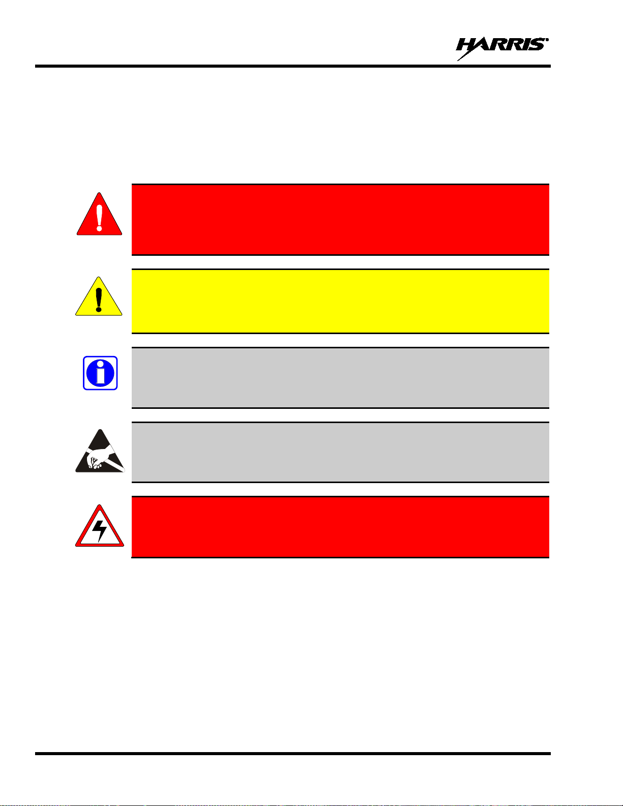
not correctly performed or adhered to, could result in personal injury. Do not
proceed beyond a WARNING symbol until the conditions identified are fully
WARNING
CAUTION
NOTE
1 SAFETY CONVENTIONS
The following conventions are used throughout this manual to alert the user to general safety precautions
that must be observed during all phases of operation, service, and repair of this product. Failure to comply
with these precautions or with specific warning elsewhere in this manual violates safety standards of
design, manufacture, and intended use of the product. Harris assumes no liability for the customer’s
failure to comply with these standards.
The WARNING symbol calls attention to a proced ure, practice, or the like, which, if
understood or met.
The CAUTION symbol calls attention to an operating procedure, practice, or the like,
which, if not performed correctly or adhered to, could result in damage to the equipment
or severely degrade the equipment perfo r mance.
The NOTE symbol calls attention to supplemental information, which may improve
system performance or clarify a process or procedure.
The ESD symbol calls attention to procedures, practices, or the like, which could expose
equipment to the effects of Electro-Static Di scharge. Proper precautions must be taken to
prevent ESD when handling circuit modules.
WARNING - The electrical hazard sy mb ol indicates there is an electrical hazard
present.
12
Page 13
MM-008212-001, Rev. L
portable radio generates RF electromagnetic energy during
transmit mode. This radio is designed for and classified as “Occupational Use
Only,” meaning it must be used only during the course of employment by
is NOT intended for use by the “General Population” in an uncontrolled
WARNING
CAUTION
2 SAFETY TRAINING INFORMATION
The Harris P5300
individuals aware of the hazards and the ways to minimize such hazards. This radio
environment.
The P5300 portable radio has been tested and complies with the FCC RF exposure limits for
“Occupational Use Only.” In addition, this Harris radio complies with the following Standards and
Guidelines with regard to RF energy and electromagnetic energy levels and ev aluation of such levels for
exposure to humans:
• FCC OET Bulletin 65 Edition 97-01 Supplement C, Evaluating Compliance with FCC Guidelines for
Human Exposure to Radio Frequency Electromagnetic Fields.
• American National Standards Institute (C95.1 – 1992), IEEE Standard for Safety Levels wi th R espect
to Human Exposure to Radio Frequency Electromagnetic Fields, 3 kHz to 300 GHz.
• American National Standards Institute (C95.3 – 1992), IEEE Recommended Practice for the
Measurement of Potentially Hazardous Electromagnetic Fields – RF and Microwave.
• DIRECTIVE 2004/40/EC OF THE EUROPEAN PARLIAMENT AND OF THE COUNCIL of 29
April 2004 on the minimum health and safety requirements regarding the exposure of workers to the
risks arising from physical agents (electromagnetic fields) and amended by:
• Directive 2007/30/EC of the European Parliament and of the Council of 20 June 2007
• Directive 2008/46/EC of the European Parliament and of the Council of 23 April 2008
• Regulation (EC) No 1137/2008 of the European Parliament and of the Council of 22 October 2008
• Directive 2012/11/EU of the European Parliament and of the Council of 19 April 2012
2.1 RF EXPOSURE GUIDELINES
To ensure that exposure to RF electromagnetic energy is within the FCC allowable
limits for occupational use and/or the exp osure li mit valu es in Ann ex A of E U Directive
2004/40/EC, always adhere to the following guidelines:
• DO NOT operate the radio without a proper antenna attached, as this may damage the radio and may
also cause the FCC RF exposure limits and/or th e exposure limit values in Annex A of EU Directiv e
2004/40/EC to be exceeded. A proper antenna is the antenna supplied with this radio by Harris or an
antenna specifically authorized by Harris f or use with this radio. (Refer to Table 7-1.)
• DO NOT transmit for more than 50% of total radio use time (“50% duty cycle”). Transmitting more
than 50% of the time can cause FCC RF exposu re compliance req uirements an d/or the exp osure limit
values in Annex A of EU Directive 2004/40/EC to be exceeded. The radio is transmitting when the
13
Page 14

MM-008212-001, Rev. L
Body
Face
“TX” indicator appears in the displ ay. The radio will transmit b y pressing the “PTT” (Pu sh-To-Talk)
button.
• ALWAYS transmit using low power when possible. In addition to conserving battery charge, low
power can reduce RF exposure.
• ALWAYS use Harris authorized access ories (an tenn as, batteri es, b elt clips, speaker/ mics, etc ). Use of
unauthorized accessories may cause t he FC C Oc c up atio nal /Cont rol led E xposu re RF co mplian c e
requirements and/or the exposure limit values in Annex A of EU Directive 2004/40/EC to be
exceeded. (Refer to Table 2-1.)
• As noted in Table 2-1, ALWAYS keep the housing of the transmitter AT LEAST 1.5 cm (0.59
inches) from the body and at least 2.5 cm (1.0 inch) from the face when transmitting to ensure FCC
RF exposure compliance requirements and/or the exposure limit values in Annex A of EU Directive
2004/40/EC are not exceeded.
Table 2-1: RF Exposure Compliance Testing Distances
TESTED DISTANCES
RADIO FREQUENCY
800 MHz 1.1 cm 2.5 cm
900 MHz 1.1 cm 2.5 cm
(worst case scenario)
The information in this section provides the information needed to make the user aware of RF exposure,
and what to do to assure that this radio operates within the FCC RF exposure limits and/or the exposure
limit values in Annex A of EU Directive 2004/40/EC.
2.2 ELECTROMA GNETIC INTERFERENCE/COMPATIBILITY
During transmissions, this Harris radio generates RF energy that can possibly cause interference with
other devices or systems. To avoid such interferen ce, turn off the radio in areas where sig ns are posted to
do so. DO NOT operate the trans mitter in areas that are sensitive to electromagnetic radiation such as
hospitals, aircraft, and blasting sites.
14
Page 15
MM-008212-001, Rev. L
or attachments could cause damage to the radio unit and may violate FCC
RF energy from portable radios may affect some electronic equipment. Most modern
WARNING
WARNING
WARNING
CAUTION
3 OPERATING TIPS
Antenna location and condition are important when operating a portable radio. Operating the radio in low
lying areas or terrain, under power lines or bridges, inside of a vehicle or in a metal framed building can
severely reduce the range of the unit. Mountains can also reduce the range of the unit.
In areas where transmission or reception is poor, some improvement may be obtained by ensuring that the
antenna is vertical. Moving a few yards in another direction or moving to a higher elevation may also
improve communications. Vehicular operation can be aided with the use of an externally mounted
antenna.
Battery condition is another important factor in the trouble free operation of a portable radio. Always
properly charge the batteries.
3.1 EFFICIENT RADIO OPERATION
For optimum audio clarity at the receiving radio(s), hold the portable radio approximately two inches
from your mouth and speak into the microphone at a normal voice level.
Keep the antenna in a vertical position when r ecei ving or transmitting a message.
Do not hold the antenna when receiving a message and, especially, do not hold when transmitting a
message.
Do NOT hold onto the antenna when the radio is powered on!
3.1.1 Antenna Care and Replacement
Do not use the portable radio with a damaged or missing antenna. A minor burn
may result if a damaged antenna comes into contact with the skin. Replace a
damaged antenna immediately. Operating a portable radio with the antenna missing
could cause personal injury, damage the radio, and may violate FCC regulations.
Use only the supplied or approved antenna. Unauthorized antennas, modifications,
regulations. (Refer to Table 7-1.)
3.1.2 Electronic Devices
electronic equipment in cars, hospital s, homes, etc. is shield ed from RF energy. However,
in areas in which you are instructed to turn off two-way radio equipment, always observe
the rules. If in doubt, turn it off!
15
Page 16

MM-008212-001, Rev. L
Areas with potentially explosive atmospheres are often, but not always, clearly
potentially explosive atmospheres are often, but not always, clearly
DO NOT remove, install, or charge batteries in potentially explosive atmosphere
WARNING
WARNING
WARNING
WARNING
WARNING
3.1.3 Aircraft
• Always turn off a portable radio before boarding any aircraft!
• Use it on the ground only with crew permission.
• DO NOT use while in-flight!!
3.1.4 Electric Blasting Caps
To prevent accidental detonation of electric blasting caps, DO NOT use two-way
radios within 1000 feet of blasting operations. Always obey the "Turn Off Two-Way
Radios" signs posted where electric blasti ng caps are being used. (OSHA Standard:
1926.900)
3.1.5 Potentially Explosive Atmospheres
marked. These may be fuelling a reas, such a s gas s tati ons, fu el or che mical t ransfer o r
storage facilities, and areas where the air contains chemicals or particles, such as
grain, dust, or metal powders.
Sparks in such areas could cause an explosion or fire resulting in bodily injury or even
death.
Turn OFF two-way radios when in any area with a potentially explosive atmosphere.
It is rare, but not impossible that a radio or its accessories could generate sparks.
Turn OFF radios when in any area with a potentially explosive atmosphere unless the
radio is Hazardous Location (HAZLOC) certified.
Areas with
marked. These may be fuelling areas, such as gas stations, fuel or chemical tra nsfer or
storage facilities, and areas where the air contains chemicals or particles, such as
grain, dust, or metal powders.
areas.
Sparks in such areas could cause an explosion or fire resulting in bodily injury or
even death.
16
Page 17
MM-008212-001, Rev. L
CAUTION
NOTE
4 CLEANING
Keep the exterior of the radio, battery, antenna, and radio accessories clean.
Periodically clean using the following procedures:
1. To remove dust and dirt, clean using damp clean cloth (warm water and mild detergent soap).
2. Follow by wiping with damp (warm water) clean cloth. Wipe dry with clean cloth.
3. Remove the battery and wipe the battery and radio contacts using a soft dry cloth to remove dirt or
grease. This will ensure efficient power tran sf er from the battery to the radio.
4. Remove any accessories and clean the accessori es Universal Device Connecto r (UDC) contacts u sing
a clean dry cloth. When the UDC is not in use, co ver the connector with the protective dust cap to
prevent the build-up of dust or water particles.
5. If the radio is used in a harsh environment (such as driving rain, salt fog, etc.), it may be necessary to
periodically dry and clean the battery and radio contacts with a soft dry cloth or soft-bristle nonmetallic brush.
For more rigorous cleaning, use the foll owing procedure:
Do not use chemical cleaners, spray, or petroleum-based products. They may damage
the radio housing. We recommend using Chemtronics® Electro-Wash® PR (ES-1603) or
equivalent.
1. Apply the cleaning solution to a clean damp cloth and clean the radio.
Do not spray cleaning solution directly on radio. To clean the radio in the speaker and
microphone areas, carefully wipe these areas but prevent the cleaning solution from
entering the speaker or microphone openings.
2. Wipe off the radio with clean damp cloth using mild warm soapy water.
3. Follow up by wiping off the radio with clean damp cloth using warm water only.
4. Wipe dry with clean cloth.
17
Page 18
MM-008212-001, Rev. L
WARNING
in safety and protection features. Should these
Failure to properly condition NiMH battery packs before initial use will result in
WARNING
CAUTION
5 BATTERIES
The P5300 series portable radios use rechargeable, recyclable Nickel Cadmium (NiCd), Nickel Metal
Hydride (NiMH), or Lithium-Ion (Li-Ion) batteries. Please follow the directions b elow to maximize the
useful life of each type of battery.
Do not disassemble or modify Lithium-Ion battery packs. The Lithium-Ion battery
packs are equipped with builtfeatures be disabled or tampered with in any way, the battery pack can leak acid,
overheat, emit smoke, burst, and/or ignite.
If the battery is ruptured or is leaking electrolyte that results in skin or eye contac t
with the electrolyte, immediately flush the affected area with water. If the battery
electrolyte gets in the eyes, flush with water for 15 minutes and consult a physician
immediately.
5.1 CONDITIONING BATTERY PACKS
5.1.1 Conditioning NiMH Battery Packs
Condition a new NiMH batt ery before putting into use. Th is also applies to rechargeabl e NiMH batteries
that have been stored for long periods (weeks, months, or longer). Conditioning requires fully charging
and fully discharging the battery three (3) ti mes usin g the t ri-che mistry charger. The first time th e b attery
is put into the charger, this unit will condition Nickel-based battery packs by automatical ly charging and
discharging (cycling) the battery. Refer to the appropriate charger manual for details.
shortened performance by the battery.
5.1.2 Conditioning NiCd Battery Packs
A new NiCd battery does not require conditioning before use. However, Harris recommends periodically
conditioning NiCd batteries to avoid t he memory effect which results when a NiCd bat tery is repeatedly
charged and not fully discharged, further resulting in a lower volt age and a lower capacity. Fortunately,
both nominal voltage and capacity are restored through battery conditioning.
Conditioning requires fully charging and fully discharging the battery three (3) times using the trichemistry charger. The first time the battery is put into the charger, this unit will condition Nickel-based
battery packs by automatically chargi ng and discharging (cycling) the battery. Refer to the approp riate
charger manual for details.
18
Page 19

MM-008212-001, Rev. L
argers and conditioners. Use of unauthorized chargers
CAUTION
Always use Harris authorized ch
and conditioners may void the warranty.
5.1.3 Storing Li-Ion Battery Packs
If a battery pack is expected to be idle for a month or more, it should be properly prepared. Li-Ion battery
packs should not be stored fully charged. Before storing the battery pack, discharge it to 40% capacity. If
the battery is not discharged prior to storage, its overall capacity may be reduced. Although all b attery
packs experience some capacity loss during storage, the shelf life for Li-Ion battery packs is about 3
months. However, note that any capacity drop which occurs during storage is permanent and cannot be
reversed. Li-Ion battery packs should be purchased and used immediately. They should not be stockpiled without a rotating stock plan.
5.1.4 Additional Information
For more information regarding the proper care of portable radio battery packs or establishing a battery
maintenance program, refer to ECR-7367 which may be ordered by calling toll free 1-800-368-3277
(international - 1-434-455-6403) or via https://premier.pspc.harris.com/infocenter/.
5.2 CHARGING B ATTERY PACKS
Battery chargers are available fro m Harris with nominal charge times. Combin ations include single and
multi-position charge units.
Harris charge rs are specifically designed for charging nickel-based and Lithium-Ion batt ery packs. The
chargers are chemistry-specific for the battery packs and automatically adjust the charging profiles
accordingly. Refer to the appropriate charger manual for specific operating instructions.
Observe the following guidelines when charging a battery pack:
• Avoid high temperature during charging.
• Discontinue use if the charger is overheating.
• Only charge Harris battery packs using a charger approved for use by Harris.
• Do not leave batteries in the charger indefini tely. For best results leave the battery in the charger for
two to six hours after the Green Ready LED comes on. Then place the battery pack into service and
fully discharge (as indicated by the radio lo w battery warning) before re-charging.
If any faults are encountered while charging the battery pack, consult the charger’s manual to determine
the cause and possible corrective action.
5.3 BATTERY PACK USAGE
Both Nickel-based and Lithium-Ion batteries vary in capacity and life cycle. For instance, NiCd batteries
have a longer life cycle than NiMH b atteries whereas NiMH batteries have a larger capacity. Howev er,
both Nickel-based and Lithium-Ion type batteries require basic usage guidelines be followed in order to
optimize the battery runtime or shift life.
The following guidelines will help optimize the battery runtime or shift life:
19
Page 20
MM-008212-001, Rev. L
has been designed to tolerate changing the battery pack without
CAUTION
• Ensure Nickle-based battery packs are fully discharged (as indicated by the radio low battery
warning) before re-charging. Full discharge is not required for Lithium-Ion battery packs.
• Periodically condition Nickel-based battery packs. The frequency should be determined based on
usage patterns (refer to ECR-7367). If the battery is fully discharged (to radio Low Battery warning)
during routine use, the frequency of conditioning may be reduced. Lithium-Ion batteries do not suffer
from memory-effect and therefore do not require conditioning.
Do NOT leave any Harris rechargeable batteries in a charger for more than a few days.
5.4 CHANGING THE BATTERY PACK
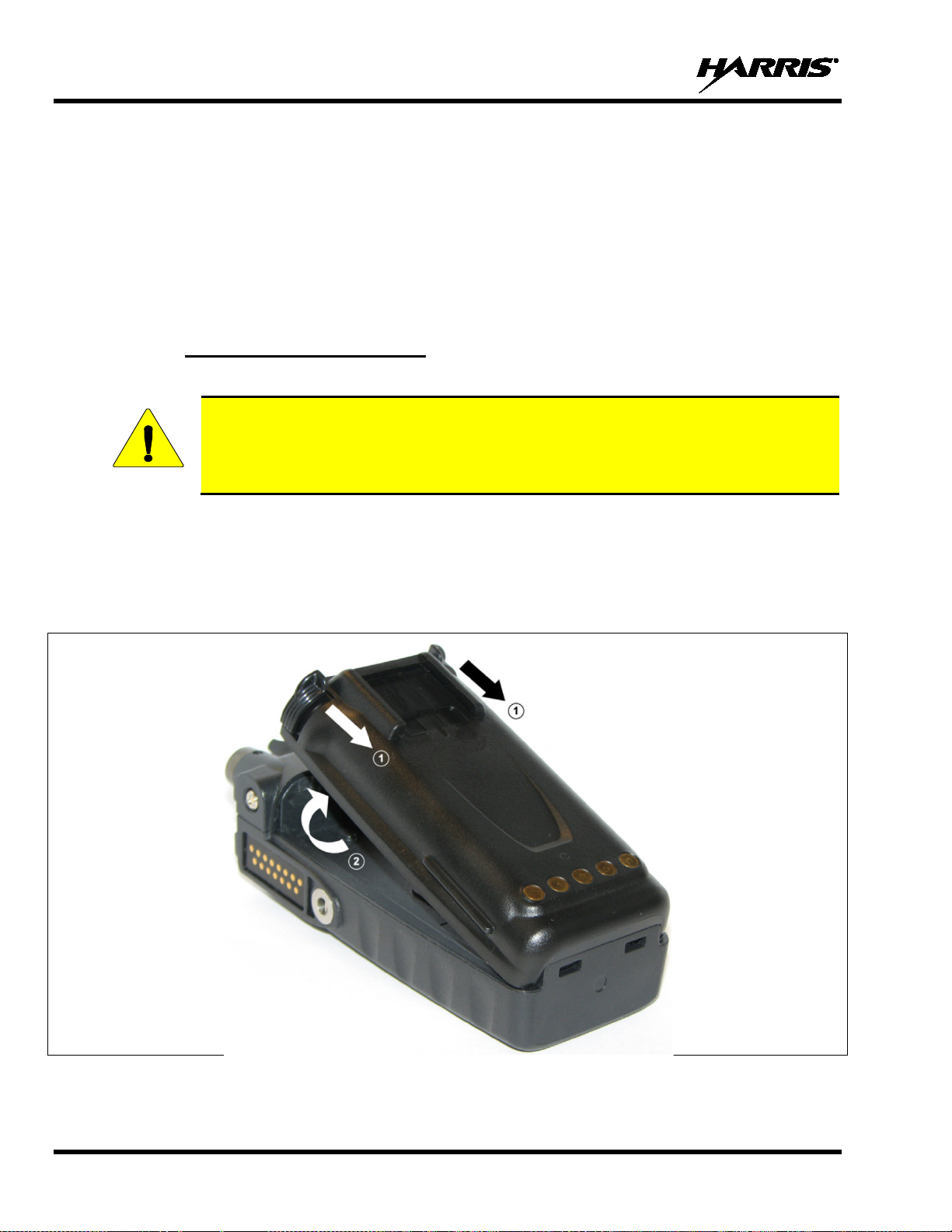
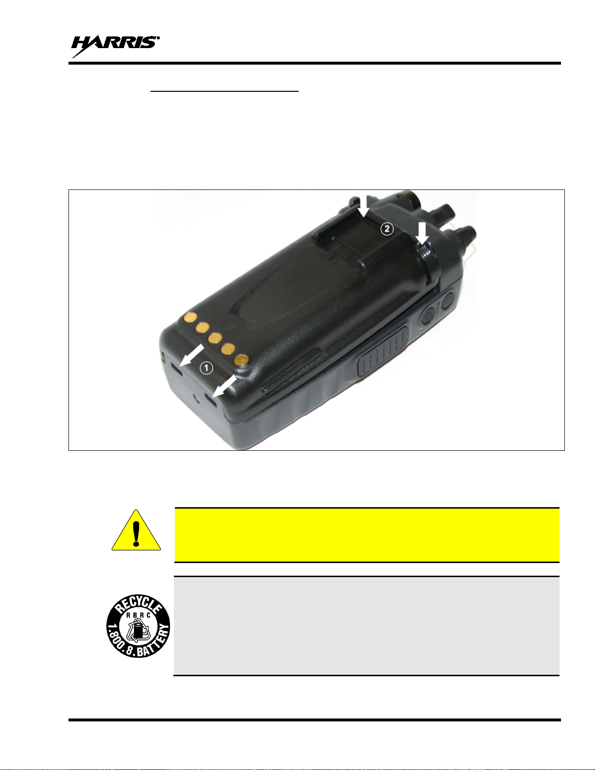
5.4.1 Removing the Battery Pack
Make sure the power to the radio is turned OFF.
Although the P5300
turning power off, Harris Corporation recommends turning the radio off before changing
battery packs to ensure safety and best operation.
1. Press or pull both latches on either side of the battery pack toward the bottom of the radio
simultaneously.
2. Pull the battery away from the radio.
3. Remove the battery pack from the radio.
20
Figure 5-1: Removing the Battery Pack
Page 21
MM-008212-001, Rev. L
you have
useful life, under various state and local laws, it may be illegal to dispose of this
for information and/or procedures for
CAUTION
5.4.2 Attaching the Battery Pack
Make sure the power to the radio is turned OFF.
1. Align the tabs at each side on the bottom of the battery pack with the slots at the bottom of the battery
cavity .
2. Push the top of the battery pack down until the latches click to attach the battery to the radio.
3. Tug gently to verify that the latches are secure and the battery pack is properly attached to th e radio.
Figure 5-2: Attaching the Battery Pack
5.5 BATTERY DISPOSAL
In no instance should a battery be incinerated. Disposing of a battery by burning will
cause an explosion.
RECHARGEABLE BATTERY PACK DISPOSAL – The product
purchased contains a rechargeable batt ery. The battery is recyclable. At the end of i ts
battery into the municipal waste stream. Check with you r local solid waste officials for
details in your area for recycling options or proper disposal. Canadian and U.S. users
may call Toll Free 1-800-8-BATTERY®
returning rechargeable batteries in y our locality.
21
Page 22

MM-008212-001, Rev. L
6 INTRODUCTION
The P5300 series portable radio is available in two models: the P5350 Scan model with a limited 6-button
front-mounted keypad and the P5370 System model with a 15-button DTMF front-mounted keypad. The
P5300 portable radio delivers end-to-end digital voice and IP data communications. It is designed to
support multiple operating modes including:
• OpenSky
• EDACS
• Conventional Analog mode
The P5300 portables can include all of these modes or just one. Additional modes of operation can be
added with software updates.
The P5300 supports a full range of advanced digital trunking features, including voice group calls,
priority scanning, emergency calls, late call entry, and dynamic reconfiguration. It performs autonomous
roaming for wide area applications. High quality voice coding and robust audio components assure
speech clarity.
In the trunked modes, the user selects a communicati ons “operating” system (i.e., OpenSky or EDACS)
and group. While communicating in a trunked mode, channel selection is transparent to the user and is
controlled via digital communication with the system controller (e.g., base station in an OpenSky system
or a CSD in an EDACS system). This provides advanced programmable features and fast access to
communication channels.
®
Trunked Protocol (OTP)
®
Trunked mode
In Conventional Analog mode, the user selects a channel and communicates directly on that channel. A
channel is a transmit/receive radio frequency pair.
The exact operation of the radio will depend on the operating mode, the radio’s programming, and the
particular radio system. Most features described in this manual can be enabled through programming.
Consult your System Administrator for the particular features programmed into your P5300.
The P5300 series portable radios operate reli ably even under adv erse conditions. These rad ios meet MILSTD-810F specifications for wind driven rain, humidity, and salt fog.
The Universal Device Connector (UDC) provides connections for external accesso ries such as a headset
or a speaker-microphone and for programming cables. The UDC is located on the right side of the radio,
opposite the PTT Button. The UDC facilitates programming and testing the radio. The UDC pins
perform different functions depending on the accessory attached t o the UDC.
22
Page 23
MM-008212-001, Rev. L
authorized accessories (antennas, batteries, belt clips,
speaker/mics, etc). Use of unauthorized accessories may cause the FCC
Occupational/Controlled Exposure RF compliance requirements to be exceeded.
) are certified by Factory
Mutual and must only be used with FM certified radios or, if applicable, Canadian
DESCRIPTION
PART NUMBER
OPTION NUMBER
ANTENNAS
¼ Wave Whip 800 MHz [CSA]
KRE 101 1223/01
MAEX-NNC1K
High Gain, Flexible Construction, 800 MHz [CSA]
KRE 101 1506/1
MAEX-NNC5K
¼ Wave Whip, 900 MHz
KRE 101 1223/02
MAEX-NNC1Z
Antenna, 764-870 MHz, Flex, End-Fed, Hi Gain
14002-0223-01
EX-NC7A
BATTERIES
Battery, NiCd, 1600 mAH
BT-023406-001
MAEX-NPA9W
Battery, NiCd, 1600 mAH, [FM] [CSA]
BT-023406-002
MAEX-NPA9Z
NiMH, immersible, [FM] [CSA]
BT-023406-004
MAEX-NPA2A
NiMH, immersible
BT-023406-003
MAEX-NPA9X
Li Ion, immersible
BT-023406-005
MAEX-NPA9Y
Lithium Polymer, immersible
BT-023436-001
MAEX-PA2U
CHARGERS
Power Adapter Kit, VC4000 Charger
PS-007810-001
MAH2-NPS9X
VC4000 Tri-Chemistry Charger
CH-017231-001
MAH2-VC4PB
Single Charger, Tri-Chemistry
CH-104560-007
MAEX-NCH9T
6-bay Charger, Li-Ion/Polymer
12082-0314-01
MAEX-CH4B
Wall Mount Kit, 6-Bay Li-Ion/Poly Charger
12082-0315-01
MAEX-AE4A
Charger, 6-Bay, Tri-Chemistry
CH-104570-007
MAEX-NCH9U
AUDIO ACCESSORIES
Speaker Mic without Antenna (cc) provision, [FM] [CSA]
MC-023933-001
MAEX-NAE9D
Earphone for Speaker Mic [FM] [CSA]
LS103239V1
MAEX-NAE3Z
Earphone for Speaker Mic, Right-Angle
LS103239V2
EX-AE1K
Ruggedized Speaker Mic, Coil Cord
MC-011617-601
MAEX-NAE6C
Standard Speaker Mic, Non-Antenna
MC-011617-701
MAEX-NAE6A
Hi-Visibility Rugged Speaker Mic, Coiled Cord
MC-011617-606
EX-AE4C
Speaker Mic, Straight Cord, 25.6 in, Antenna
MC-011617-703
MAEX-AE6L
WARNING
CAUTION
NOTE
7 OPTIONS AND ACCESSORIES
Table 7-1 lists the Option s and Accessories tested for use with th e P5300 series portable radios. Refer to
the Products and Serv ices Catalog for a complete list of options and accessories, including those items
that do not adversely affect the RF energy exposure.
Always use Harris
(Refer to Table 2-1.)
Always use the correct options and accessories (bat tery , anten na, speaker/ mic, etc.) for th e
radio. Immersion rated options must be used with an immersion rated radio. Hazardous
Location (HAZLOC) certified options (identified by [FM]
Standards Association [CSA] certified radios. (Refer to Table 7-1.)
Refer to the product label or HAZLOC certif ication for class, division, and temperature
rating.
Table 7-1: Options and Accessories
23
Page 24

MM-008212-001, Rev. L
DESCRIPTION
PART NUMBER
OPTION NUMBER
Speaker Mic, Straight, 18 in, Antenna
MC-011617-718
MAEX-AE6M
Speaker Mic, Straight, 30 in, Antenna
MC-011617-730
MAEX-AE6N
Speaker Mic, Rugged, Antenna, Straight
MC-011617-602
MAEX-NAE6D
GPS Speaker Mic
MC-009104-002
MAEX-NAE9R
Speaker Mic, Rugged, Coiled Cord
MC-011617-611
EX-AE4K
DROP SHIP AUDIO ACCESSORIES
Earphone Kit, Black
EA-009580-001
Earphone Kit, Beige
EA-009580-002
2-Wire Kit, Palm Mic, Black
EA-009580-003
2-Wire Kit, Palm Mic, Beige
EA-009580-004
3-Wire Kit, Mini-Lapel Mic, Black
EA-009580-005
3-Wire Kit, Mini-Lapel Mic, Beige
EA-009580-006
Explorer Headset with PTT
EA-009580-007
Lightweight Headset Single Speaker with PTT
EA-009580-008
Breeze Headset with PTT
EA-009580-009
Headset, Heavy Duty, N/C Behind-the-Head, with PTT
EA-009580-010
Ranger Headset with PTT
EA-009580-011
Skull Mic with Body PTT and Earcup
EA-009580-012
Headset, Heavy Duty, N/C Over-the-Head, with PTT
EA-009580-013
Throat Mic with Acoustic Tube and Body PTT
EA-009580-014
Throat Mic with Acoustic Tube, Body PTT, and Ring PTT
EA-009580-015
Breeze Headset with PTT and Pigtail Jack
EA-009580-016
Hurricane Headset with PTT
EA-009580-017
Hurricane Headset with PTT and Pigtail Jack
EA-009580-018
CARRYING CASE ACCESSORIES
used with Belt Loop
used with: KRY 101 1609/1
Nylon Case (black) with Belt Loop
CC-023932-001
used with Swivel Mount
Kit: CC-014528-004
KRY 101 1608/2
Standard Leather Case with Belt Loop Kit, consists of:
used with Swivel Mount
KRY 101 1608/2
Standard Black Nylon Case with Belt Loop Kit, consists of:
Standard Leather Belt Loop
Kit: CC-014534-002, incl:
CC-014527
Standard Restraining Strap
Metal Belt Clip (standard)
CC23894
MAEX-NHC7P
Leather Belt Loop with Swivel
FM-017262-001
KRY1011609/1
MISCELLANEOUS
Adapter, UDC, GPS
14002-2014-01
Adapter, UDC, Bluetooth
14002-2015-01
Leather Carrying Case without D-Rings Kit, consists of:
Leather Case without D-rings
Elastic Strap
Swivel Mount,
Standard Leather Case with Shoulder Strap Kit, consists of:
Standard Leather Case with D-Rings
Shoulder Strap with Loop for Speaker/Mic
Standard Leather case without D-Rings
Standard Leather Belt Loop
Standard Black Nylon Case
used with Shoulder Strap with Loop for Speaker/Mic
Kit: CC-023931-003, incl:
CC-023931-001
FM-011820
KRY 101 1608/2
KRY 101 1609/1
, incl:
CC-014528-002
CC-014524-001
Kit: CC-014528-003, incl:
CC-014528-001
CC-014527
CC-014534-001
CC-014524-002 MAEX-NHC9V
MAEX-NHC9L
MAEX-NHC9M
MAEX-NHC9S
MAEX-NHC9T
MAEX-NHC9U
MAEX-NHC7T
24
Page 25

MM-008212-001, Rev. L
8 CHANGE OPERATING MODE
8.1 CHANGE FROM OTP MODE
To change from OTP operating mode to EDACS/P25/Conventional (ECP):
1. Use or
2. Use or to choose an available mode. Press and or to confirm (Y/N).
3. Press the button to confirm.
Or
With a system model radio, press 1# to transition to ECP.
Or
If configured, turn the A/B Switch to the A or B position.
to cycle through the menu until “App Mode” is displayed.
8.2 CHANGE TO OTP MODE
1. Use or to scroll through available systems until OpenSky is displayed and wait.
2. The radio transitions to OTP mode.
25
Page 26
MM-008212-001, Rev. L
9 OPENSKY OPERATION
Once an OpenSky system has been selected from the available systems on your P5300 series portable
radio, the characteristics described in the following sections will govern operation.
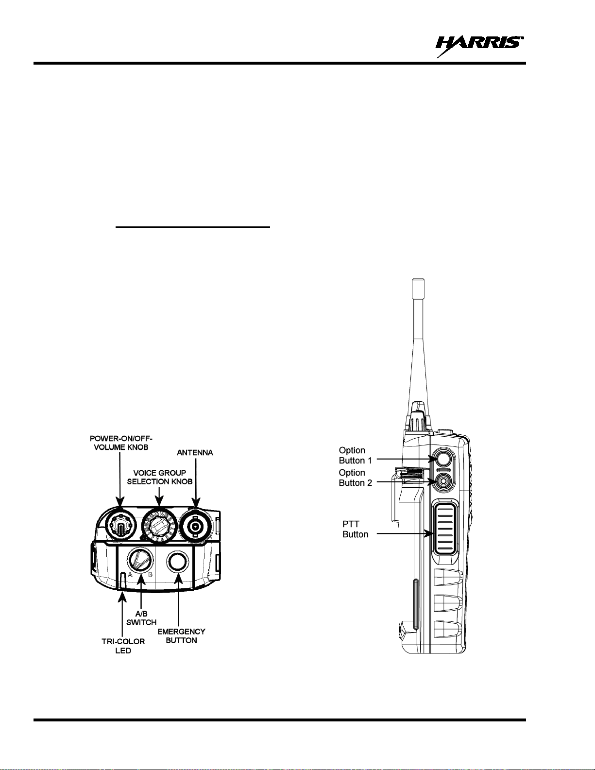
9.1 CONTROLS
The P5300 portable radio features two rotary control knobs, an emergency button, and a dual-position
A/B switch, all located on the top of the radio (see Figure 9-1). The Push-To-Talk (PTT) button and two
option buttons are located to the left side of the radio keypad (see Figure 9-2). The front mounted keypad
of the P5370 “System” model has 15 buttons and the P5350 “Scan” model has six buttons.
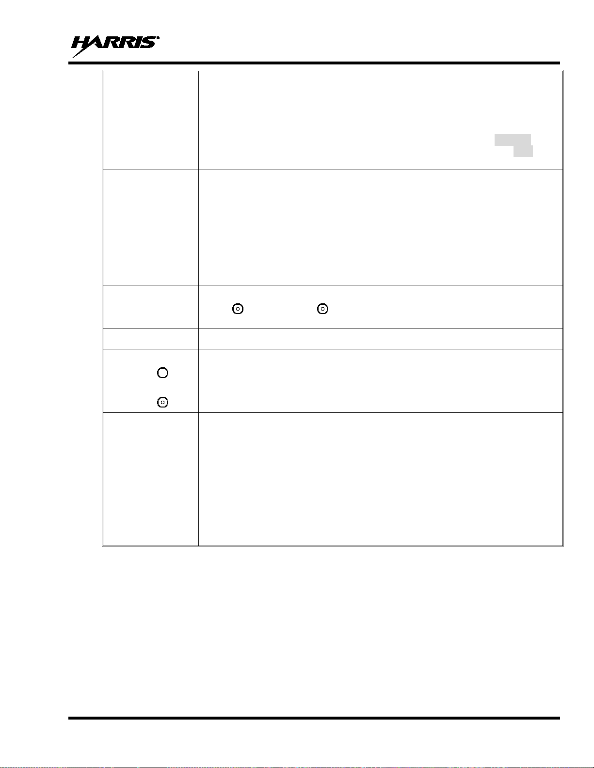
9.1.1 Buttons, Knobs, and Switch
The functions of the buttons, knob controls, and dual position A/B Switch vary depending on the mode of
operation. Their functions while in the OpenSky mode of operation are discussed in the following
paragraphs.
26
Figure 9-1: Top View
Figure 9-2: Side View
Page 27
MM-008212-001, Rev. L
Rotating the control clockwise applies power to the radio. A single alert tone (if
he volume level. While adjusting the
). The
in the
display) up to 39, which is the loudest level.
Used to select voice groups when operating within an OpenSky system. This is a
A mechanical stop, which can limit the number of positions accessed, is shipped
the mechanical stop, remove the
voice group selection knob, loosen the set screw on the voice group selection knob
metal base (using a 1.27 mm hex wrench), and remove the voice group selection
stop ring located at
install the voice group selection knob metal base, tighten
the set screw, and re-install the voice group selection knob.
Option 2
press the emergency button. Release both buttons
when the “emergency cleared” tone sounds.
PTT BUTTON
The Push-To-Talk button must be pressed before voice transmission begins.
menu, such as available talk
The following settings are configurable v ia t he at @abcswitch command:
• Scan Mode - Fixed (See Section 9.20.1).
POWER
ON/OFF
VOLUME KNOB
VOICE GROUP
SELECTION KNOB
EMERGENCY
BUTTON
SIDE OPTION
BUTTON 1
SIDE OPTION
BUTTON 2
Applies power to the radio and adjusts audio volume.
enabled through programming) indicates t he radio is operational.
Rotating the control clockwise increases t
volume the display will momentarily indicate the volume level (i.e., VOL=31
volume range is from a minimum programmed level of 1 (displayed as OFF
16-position rotary knob.
with the radio but must be installed. To install
knob metal base. Replace the 16 channel ring with the channel
the desired channel. Re-
Press to declare an emergency. To clear an emergency, press and hold
button . While holding ,
Scrolls up or down thru available items within a subgroups, pre-programmed speed dial numbers, ca nned alert messages, etc.
A/B SWITCH
• No Action.
• V-TAC Detach (same as *60).
• V-TAC Attach (same as *61, *62, or *62 depending on at@cmode setting).
• Change to ECP mode.
• Scan Mode - No Scan (See Section 9.20.1).
• Scan Mode - Normal (See Section 9.20.1).
27
Page 28
MM-008212-001, Rev. L
Secondary function: While in the “dwell display,” press repeatedly to scroll
(P5370 Only)
numeric passwords for
configured for automatic
unit) calls,
d. Additional functions are also
TAC, voice scanning, and
Initiates OpenSky functions (log in, log out, selective call, telephone
escape or to clear an entry (something like backspace, but it clears
9.1.2 Keypad
Alpha-numeric character entry is th e function of most of the P5300 keypad keys while in the OpenSky
mode of operation, in addition to the (*) and (#) key s which are also available. Refer to Table
9-1 in this section for the function of the keys while in OpenSky mode.
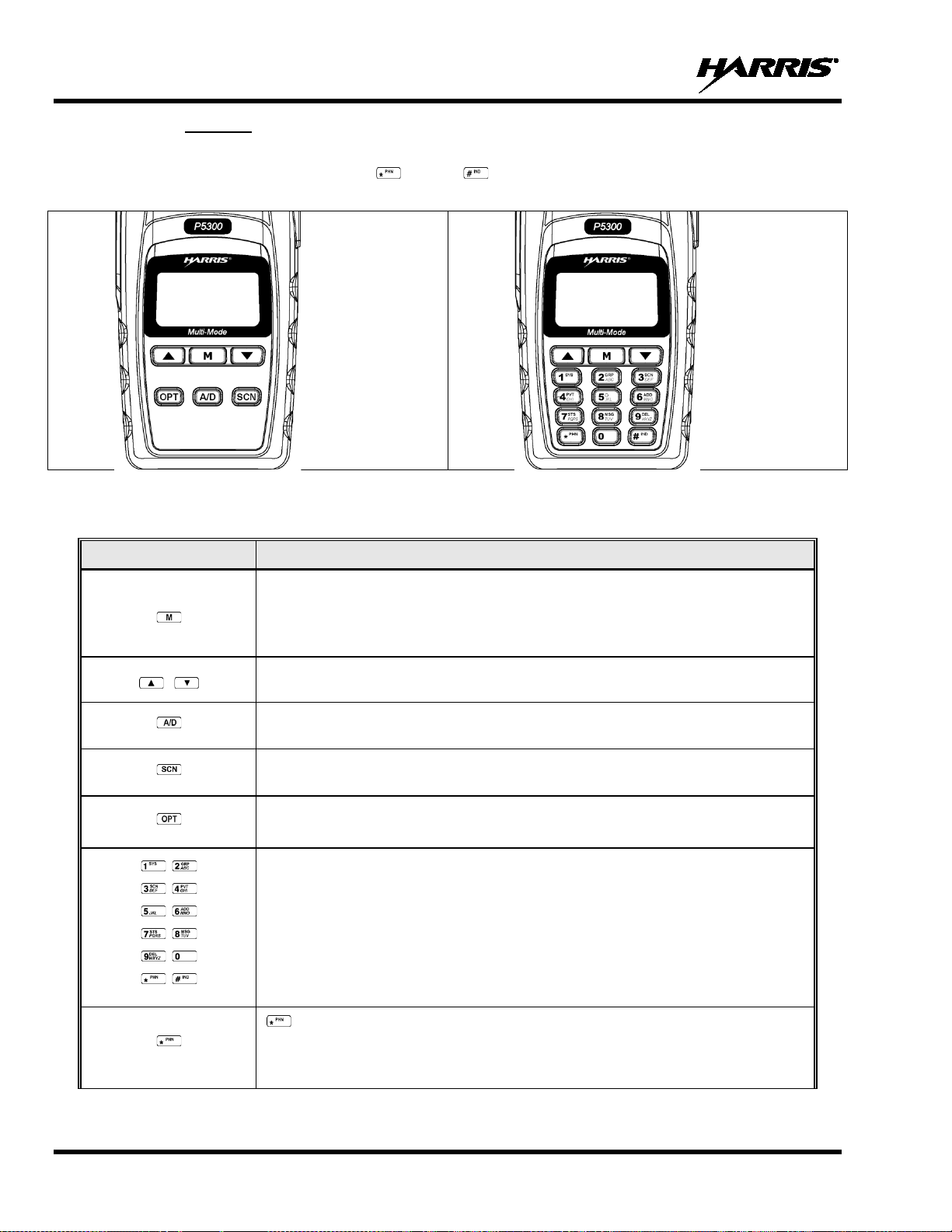
Figure 9-3: P5350 Scan Model Front Panel Figure 9-4: P5370 System Model Front Panel
Table 9-1: Keypad Functions
KEY FUNCTION
Primary function: Acts much as an “enter” button to acti vate a selection.
(P5350 only)
(P5350 only)
(P5350 only)
through and view status display (on 2nd line) for current profile, caller, received
talk group, and channel.
Scrolls thru available menu items (see Table 9-4).
Currently undefined.
Toggles scan function On and Off.
Currently undefined.
The alpha-numeric keys are used to enter alphalogging into the OpenSky network, if not preregistration at power-up.
Also used to place telephone interconnect and individual (unit-tooperating like a normal telephone keypa
available, such as speed dial, quick access to VStealth mode operation.
(P5370 Only)
28
interconnect call, etc.). See page 38 for additional information. It is also used
as an
everything and not only the last digit/character).
Page 29
MM-008212-001, Rev. L
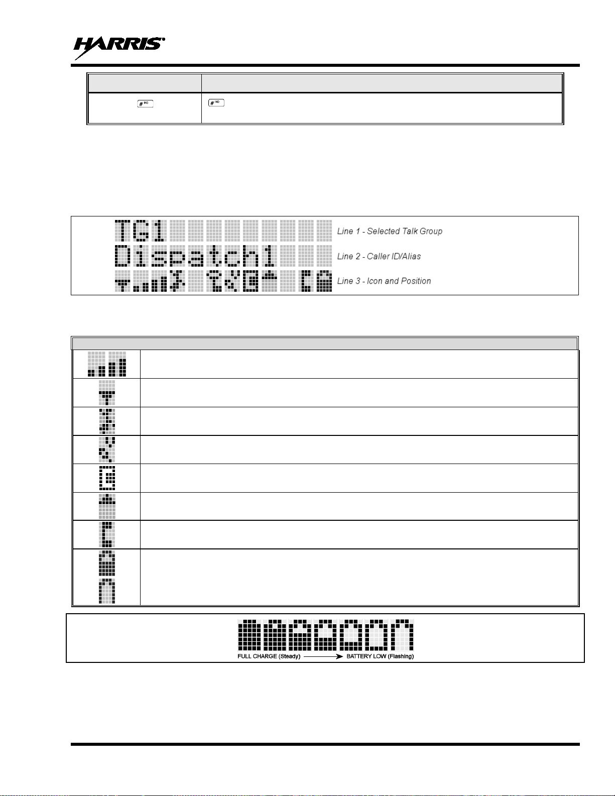
(P5370 Only)
OPENSKY ICONS
KEY FUNCTION
9.2 DISPLAY
The P5300 display is made up of 3 lines. Lines 1 and 2 contain twelve alpha-numeric character blocks
each. The 3
display backlighting will illuminate upon power up or when radio controls are operated. Specific display
characteristics will be discussed in following sub-sections.
Table 9-2 describes the icons displayed by the radio during OpenSky operation.
rd
Steady – Received Signal Strength Indicator (RSSI).
Steady – Radio is data registered.
Used in conjunction with alpha-numeric keys for passwords and OpenSky
functions. See page 38 for additional information.
line also contains twelve blo cks, each u sed to disp lay radi o stat us i co ns. If p rog ra mmed, t he
Table 9-2: Status Icons Descriptions
Steady – Stealth mode is enabled, all tones and the display backlight are disabled, voice is still heard.
Animated – The radio is scanning for a V-TAC. Once the radio has attached to a V-TAC, the icon will turn off.
V-TAC Connection Indicator – Indicates the client is connected to a V-TAC.
Steady – Indicates Voice Scan mode is Normal or Fixed. Is not displayed when Voice Scan mode is No Scan.
Steady – Indicates Selective Call mode.
Steady – Battery charge indicator.
Flashing – Low battery indicator.
Figure 9-5: Full Cycle Battery Charge Indicator
The battery charge indicators illustrate approximate level only, based on battery voltage. Refer to Figure
9-5.
29
Page 30

MM-008212-001, Rev. L
9.3 TRI-COLOR L ED
Figure 9-6: Tri-Color LED
The Tri-Color LED changes color to indicate radio status and is visible from both the front and top of the
radio (see Figure 9-6). The radio states reflected by the LED are:
Green: Receiving
Red: Transmitting
If the LED is flashing rapidly, the radio is receiving an emergency call. If the
LED is flashing every ½ second, the selected talk grou p is in th e emergency state
(although not transmitting). If the selected talk group is in the emergency state,
an asterisk will be displayed next to the talk group name.
9.4 LOG IN TO THE NETWORK
Log in occurs either auto matically (auto registration) if the radio has a valid registration or, if enabled,
requires the user to enter a User ID and password.
To manually register:
1. Press *1.
2. Enter the full 10-digit User ID.
3. Press the key.
4. Enter the password.
• If the radio is configured for alpha-numeric passwords and the password has consecutive
duplicate numbers (“MES33” for example), enter #, the key, between the consecutive
duplicate numbers so the radio will not interpret t he entry as a letter (“D” in this example).
• If the radio is configured for numeric-only passwords, do not press the key between
duplicated numbers.
5. Press the key twice for alphanumeric p asswords; press the once for numeric only passwords.
The User ID may be remembered from the previous log in. (Refer to Section 9.5 for further details
regarding log-off commands.) The password will be established before the radio is put into operation.
Contact the local OpenSky network administrator for more information.
30
Page 31

MM-008212-001, Rev. L
NOTE
If necessary, contact radio system ad ministration personnel for log in assistance and/or
radio-specific log in instructions.
9.5 LOG OFF THE NETWORK
The *0## command de-registers the radio. Typically, this is automatically performed when powering
down the radio. Using this method, the User ID is remembered by the radio so only the password is
needed at next log in.
If a user is logged in, it is necessary to log-off.
9.6 PERSONALITY
As illustrated in Figure 9-7, a personality defines the profiles and talk groups available to the u ser. It is
the structuring of a collection of profiles and privileges established by the OpenSky network administrator
to provide the user with a comprehensiv e set of profiles to communicate effectively with the necessary
talk groups or individuals.
Personalities are stored on the network and downloaded over-the-air to the radio. This process is called
“provisioning.” Provisioning occurs at radio power-up (if the personality is not already stored in the
radio’s memory) and at user log in (if the radio has been deregistered). When changes are made to the
personality, the radio is automatically re-provisioned. Each personality can contain up to sixteen (16)
profiles and each profile can contain up to sixteen talk groups.
9.6.1 Profiles
As stated above, each profile can contain up to sixteen (16) talk groups. A profile also defines the radio’s
emergency behavior. All transmissions are made on the selected talk group (displayed on the top line of
the dwell display). The user can change the selected talk group to any of the other talk groups within the
profile.
31
Page 32

MM-008212-001, Rev. L
TG a
TG b
TG c
TG x
TG y
TG z
TG d
TG e
TG f
TG a
TG d
TG g
TG h
TG i
TG = Talk Group
Profile 1
Profile 2
Profile 3
Figure 9-7: Personality Structure Example
9.6.2 Talk Groups
A talk group represents a set of users that reg ularly need to commun icate with one another. There can be
any number of authorized users assigned to a talk group. Talk groups are established and organized by the
OpenSky network administrator. An OpenSky talk group is similar to a channel within a conventional FM
radio system.
9.7 OPENSKY DISPLAY OVERVIEW
The 12-character x 3-line display shows the radio status. The first two lines of the display are text lines
that change in response to user interaction with the menu buttons. Status icons appear in the bottom line
(line 3) of the display (see Table 9-2).
9.7.1 Display’s Top Line
The display’s top line of text changes as the and buttons are pressed to scroll through the
available menu options (see Table 9-4). When the dwell display is present, the select ed talk g roup will be
displayed. Other information, such as al er t messages will scroll across the top line of the display.
9.7.2 Display’s Second Line
The second line will display information such as active menu, log in p rompt, emergency status, and dwell
display messages as described in the following section.
9.7.3 Dwell Display
When not engaged in menu selection, the first two lines of the display default to the user-defined display,
known as the “dwell display.” The top lin e indicates the currently selected talk group. The second line
will display the currently selected profile, cal ler ID/alias
(if the channel menu is enabled). Press the button repeatedly to scroll through and view one of these
second line options.
1
, received talk group, and current channel name
1
Alias is a logical ID name such as “J_Smith.” The name corresponds to a user ID such as 003-542-0001.
32
Page 33

MM-008212-001, Rev. L
NAME
TONE
DESCRIPTION
Call Queued
One low tone/two high tones
Call is queued for processing.
Call Denied
Three short beeps
Radio is out of coverage area or requ ested talk group is active.
second grant tone to let the user know they have roamed.
coverage area or pre-empted by higher-priority call).
pitched
network drops the call if unans wered after one (1) minute.
If enabled via programming, sounds at a programmable interval
Sounds when the current received call is preempte d by a
Sounds when a radio connects to a V-TAC in XCOV, XCOV-
Menu.
Sounds when a radio connects to a V-TAC in XCOV, XCOV-
Menu.
Single long low-pitch tone
pitched tone
Sounds when the man down accessory is connect to the radio’s
9.8 ALERT TONES
The P5300 radio also provides audible Alert Tones or “beeps” to indicate the various operating conditions
(see Table 9-3).
Grant (or Go-Ahead) Single short beep
Table 9-3: Alert Tones
Sounded when resources become available for a call request
placed in the queue (if enabled) upon c hannel access.
If the radio roams to another site whil e transmitting, then it will
auto rekey and begin transmitting on t hat tower. It gives a
Call Removed Single long low-pitched tone
Low Battery
Selective Alert Received Four short tones
Emergency Alert Tone Three long beeps Sounds when an emergency alert is declared.
Emergency Cleared Tone Single long low-pitched tone Sounds when an emergency is cleared.
Selective Call Ring Tone
Roam Tone
Out of Range Tone Three brief tones
Priority Bump
XCOV Connect Tone
or
Site Found Tone
One low-pitched/one short mid-
A ringing tone similar to a
telephone
Two short tones, one highpitched and one low-pitched
Single medium mid-pitched
tone
Three short high-pitched tones
Notifies the user access to the channel has been lost (out of
Low battery.
Only played once to indicate a selective alert has been
received.
Ringing is repeated every four (4) seconds until the call is
accepted or rejected by the radio bein g called or until the
Sounds when the radio transitions from one radio base station
site to another. While transmitting voice.
while the radio is in a state of persistent deactivation.
higher priority call.
TG, or XCOV-Prof mode.
Sounds when the selected site is found using the Site Lock
XCOV Disconnect Tone
or
Site Not Found Tone
Man Down Tone
Three short high-pitched tones
followed by a single short high-
TG, or XCOV-Prof mode.
Sounds when the selected site is not f ound using the Site Lock
UDC port and the radio is a horizontal.
33
Page 34

MM-008212-001, Rev. L
MESSAGE
DESCRIPTION
conditions, contact your system administrator.
your system administrator.
UNAUTH3
Unauthorized IP. The radio network ID has not been added to network.
system administrator.
your system administrator.
system administrator.
DUP IP
Duplicate IP.
BADIKEY
Invalid infrastructure public key sequence number (IPKSN).
BADEKEY
Invalid end-system public key sequence number (EPKSN).
conditions, contact your system administrator.
contact your system administrator.
contact your system administrator.
MDS BSY
MDIS busy – retry.
your system administrator.
KEYSYNC
Mismatched key sequence number.
UNK ALG
Unknown/unsupported encryption algorithm.
BADSIZE
Unsupported MDIS key size.
If condition persists in strong signal
conditions, contact your system administrator.
your system administrator.
If condition persists in strong signal conditions,
contact your system administrator.
If condition persists in strong signal
conditions, contact your system administrator.
9.9 ERROR MESSAGES
This section lists and describes the erro r messages that may be displayed by the radio durin g OpenSky
operation.
NOAUT01
MDENIED
UNAUTH4
UNAUTH5
MDISBSY
UNK MES
NOAUT05
Unspecified MDIS (data switch) error. If condition persists in strong signal
Unspecified MDIS error. If condition persists in strong signal conditions, contact
Bad authentication. If condition persists in strong signal conditions, contact your
Unsupported authentication. If condition persists in strong signal conditions, contact
The MDIS is busy. If condition persists in strong signal conditions, contact your
Unknown mobile end system (MES); i.e., radio. If condition persists in strong signal
MDIS failed mutual authentication. If condition persists in strong signal conditions,
BADMDIS
UNK DOM
NOAUT11
NOAUT12
NOREPLY
VDENIED
MDIS failed mutual authentication. If condition persists in strong signal conditions,
Unknown home domain. If condition persists in strong signal conditions, contact
Radio failed data mutual authentication.
No response from MDIS. If condition persists in strong signal conditions, contact
No SME response from MDIS.
Unspecified VNIC (voice switch) error.
34
Page 35

MM-008212-001, Rev. L
MESSAGE
DESCRIPTION
BAD VID
Invalid voice User ID. Check User ID. If correct, contact your system administrator.
Retry. If error continues, contact your system
administrator.
SRV BSY
The serving VNIC is busy (congested).
radio.
NAS BSY
The system cannot provision radio because of an administrative process.
contact TAC (see Section 11.2).
conditions, contact your system administrator.
signal conditions, contact your system administrator.
PLS LOGIN
Log in with keypad.
BAD PWD
An invalid password has been entered. Verify the password and re-enter.
The radio will cease transmitting if it exceeds an
Report this failure to authorized technician.
No App
ECP mode is unavailable (not programmed).
NO PRIV
Missing required privilege.
conditions, contact your system administrator.
Dead battery
Radio must shutdown because battery charge is critically low.
NO REG
Not registered with MDIS, VNIC, or both.
DISABLED
Function disabled (e.g., function invalid in current context).
HOM DWN
MAX USR
NOAUTHM
NOSUPRT
NOAUTHV
OVER_TEMP
The Home VNIC is down.
The maximum number of users are already registered with the specified User ID.
OpenSky allows one User ID to log onto the network using up to three different
radios. Use *0## command or power down one of the other radios to de-register the
The radio failed voice mutual authentication. If a valid radio displays this error,
The radio cannot support the required provision. If condition persists in strong signal
VNIC does not support or failed mutual authentication. If condition persists in strong
The radio may be too hot.
operational temperature threshold. Let the radio cool before attempting to transmit.
NO SYNC
No forward-channel sync (weak or no coverage). If condition persists in strong signal
35
Page 36

MM-008212-001, Rev. L
MENU
NAME
RADIO
DISPLAYS
To/From Dwell
Display
bit-error rates,
registration status
Silent
Emergency
and
confirm (Y/N) with or and again.
to base station [“GPS (Site)”] or
Station
Identification
Stealth Mode
is disabled)
for more
.
Display
Brightness
to
See Next Page
9.10 BASIC MENU STRUCTURE
Table 9-4 illustrates the basic P5300 OpenSky menu structure. Menu items will vary depending upon
system programming, radio hardware, and optional configurations. All menus except the dwell display
menu can be turned off by network administration personnel.
Table 9-4: Basic P5300 OpenSky Menu Structure
USAGE NOTES
Engineering
Display
Operating Mode
GPS Fix
User ID
IP Address
RSSI data, sync
status, current
channel and
“SilentEmerg”
“App Mode”
“GPS”
“User ID”
“IP Address”
“Station ID”
Displays radio system connection data. For engineering use.
Use or to toggle between OFF/ON. Press to enable.
Use or to choose an available mode (OTP, OCF, or ECP). Press
GPS latitude and longitude position of currently tunedV-TAC (“GPS”) scrolls across top line of the display. “GPS (Aged)” indicates V-TAC
coordinates haven’t been updated f or more that 2 minutes.
User’s identification/name scrolls across top line of the display (if programmed).
Radio’s Internet Protocol (IP) address scrolls across top line of the display.
Station’s identification/name scrolls across top line of the display (if programmed).
(display backlight
Treble Level
Side Tone Level
36
“StealthMenu”
“Treble Menu”
“Bright Menu”
“Side Menu”
Use or to turn Stealth Mode “On” or “Off.” See Section 9.15
information about Stealth Mode.
Use or to choose speaker trebl e level (LOW, MEDIUM, MEDHIGH, or HIGH)
Press to return to dwell display.
Use or to brighten or dim backlighting. Pr ess to return to dwell display.
Use or to choose si de tone level (OFF, LOW, MED, or HIGH). Press
return to dwell display.
Page 37

MM-008212-001, Rev. L
MENU
NAME
RADIO
DISPLAYS
See Previous Page
Selected
Channel
.
to toggle “<”
Talk group
Priority 1
all
to go to the “Alert Msg” menu.
to send message and
to return to dwell
display.
status led “On” or “Off.” When On, t he LED flashes red when
the radio transmits, green when rec eiving, a nd amber when in emergenc y. When Off,
the LED will not light at all.
Status Message
message.
Request to Talk
Message
message.
Mode
Dismiss
to toggle “<” on (dismiss )
and off.
See Next Page
USAGE NOTES
Scan Mode
Talk group
Lock Out
Priority 2
Talk group
Alerts Received
Alert Destination
“ChannelMenu”
“ScnModeMenu”
“LockOutMenu”
“Priority2”
“Priority1”
“Alerts Rcvd”
or oldest message
“Alert Dest”
Displays the current channel. Press to return to dwell display.
Use or to scroll through available scan modes (Normal, No Scan, or F ixed)
Press to return to dwell display.
Use or to choose a talk group for locking/unlocking. Press
on (locked out) and off.
Use or to choose Priority 2 talk group. Press to return to dwell display.
Use or to choose Priority 1 talk group. Press to return to dwell display.
“No alerts” or alert message t ext scrolls in display. Use or to scroll throu gh
messages.
Use or to choose a speed-di al number. Press
Use or to scroll through “canned messages.” Press
return to dwell display.
Speed Dial
Profile Selection
Talk group
Selection
Status LED
V-TAC Client
Emergency
“Speed Dial”
“ProfileMenu”
“TalkGrpMenu”
“Status LED”
“Status Msg”
“RTT Msg”
“Client Mode”
“EmgDismiss”
Use or to choose a speed-dial number and press PTT to place call.
Use or to choose an available profile. Pres s to return to dwell display.
Use or to choose a talk group in current p rofile. Press
Use or to toggle
Use or to scroll through available messages. Press to send the selected
Use or to scroll through available messages. Press to send the selected
Use or to choose Client Mode (Network, XCOV, XCOV-TG, or SOI).
Use or to choose emergency talk group. P ress
37
Page 38

MM-008212-001, Rev. L
MENU
NAME
RADIO
DISPLAYS
See Previous Page
OTP Software
Version
to reset RF
diagnostics counters.
Group
to toggle “<” on (selected)
and off.
Use and to scroll through menus.
KEYPAD
COMMAND
*0
Log-off command: *0## (logs the user off the system). See Section 9.5 for add itional information.
*1
Log in command: *1<User ID> # <Password> ##.
*2
Status Message: *2 <0...9> #. See Section 9.25 for more information.
Exit SOI Mode with *40#
*5
RTT Message: *5 <0...9> #. See Secti on 9.26 for more information.
additional information.
*8
Radio-to-Radio Call command: *8<Selectiv e c al l number># (PTT to dial).
dial).
Extended coverage for individual users. Refer to Section 9.29.1 for more information.
Extended coverage for a talk group. Refer to Section 9.29.1 for more inf ormation.
*63
Initiate XCOV-PROF Mode command: *63#. Refer to Section 9.29.6 for more information.
*60
Exit XCOV, XCOV-TG, or XCOV-Prof Mode: Returns to the Network mode.
USAGE NOTES
Site Lock
“Software Ver”
RF Diagnostics
Priority 3 Talk
“Diagnostics”
9.11 KEYPAD
9.11.1 Keypad Function Commands (P5370 Only)
To perform a command from the keypad, use the keypad commands in Table 9-5.
“Site Lock”
“Priority 3”
Use or to scroll through sites. Press to select s i te.
Displays OTP software version Press t o return to dwell display.
Use or to scroll through RF diagnostics displays. Press
Use or to choose Priority 3 talk group. Press
Table 9-5: Keypad Function Commands
FUNCTION
Enter Scene of Incident Mode (SOI) on specified channel and band: *4#<Chan>#<Band>#
where Chan is the channel number that i s being used as a SOI repeater and band is the num ber
*4
*7
*9
*61
*62
assigned to each frequency band. F or example, if Channel 25 800 MHz (band 0) is being used for
SOI, then enter *4#25#0#.
Initiate Selective Alert command: *7<Target ID>#[Choose Message]#. S ee S ection 9.22 for
Public Switched Telephone Network (PSTN) Call command: *9 <telephone num ber># (PTT to
Initiate XCOV Mode command: *61#
Initiate XCOV-TG Mode command: *62#
38
Page 39

MM-008212-001, Rev. L
QUICK
KEYS
Transition to ECP Mode
If ECP code is not loaded in the radio, “No App” appears in the display.
2#
Toggles Stealth Mode On/Off
Toggles Scan Mode On/Off (Normal/Fixed, see details below)
toggled On.
Lights/Tones On/Off
If the radio is in Stealth mode, this quick key is disabled since the user is not able to turn on the
light/tones in stealth mode.
This quick key sequence is used to set the current active profile to the default profile in the personality as
defined in the UAS.
XCOV & XCOV-TG Attach/Detach
TAC, the
will attempt to attach to another V-TAC.
7#
This quick key sequence is used to t rasmit the RTT Automatic Normal Message to the c onsole.
8#
This quick key sequence is used to tr ansmit the RTT Automatic Priority Message t o the console.
9.11.2 Quick Keys (P5370 Only)
Quick Keys are a two-button sequen ce that provides the user with quick access to certain menu items.
Quick Keys function as a toggle for these menu items.
Table 9-6: Quick Key Sequence
FUNCTION
1#
• If the Scan Mode is Normal when the Scan Mode is toggled Off, the Scan Mode will be Norm al when
toggled On again.
3#
4#
• If the Scan Mode is Fixed when the Scan Mode is toggled Off, the Scan Mode will be Fixed when
scan mode is toggled On again.
• If the Scan Mode is Off when the radio boots up, the Sc an Mode will be Normal when Scan Mode is
Pressing 4# turns the TX/RX LEDs, B ac klight, and Side Tones On/Off.
If any of the TX/RX LEDs, B acklight, and/or Side Tones are On, a nd this quick key sequence is use d,
then all of the TX/RX LEDs, Backlight , and Side Tones are turned Off.
5#
6#
9.11.3 DTMF Overdial
Using the keypad on a System Model, the radio can transmit DTMF tones corresponding to
numbers/characters 0 - 9, *, and # on the keypad. To overdial numbers/characters, transmit by pressing
and holding the PTT button and then, press the corresponding keys (one at a time) on the keypad.
9.11.4 Lock/Unlock the Keypad
1. Press and hold the button.
This quick key sequence is used t o manually connect to a V-TAC. When attaching to a Vradio’s programming determines whether to attach to the V-TAC in XCOV or XCOV-TG mode.
• If the user attaches to a V-TAC manually, using the *61# or *62# command sequenc e, the radio is
understood to be attached and this quick key sequence will detach the radio from the V-TAC.
• If the user detaches manually from a V-TAC using the *60# command sequence, the radio is
understood to be detached and this qu i c k key sequence will attach the radio to a V-TAC.
• At bootup, the radio is understood to be deta ched fr om a V-TAC. If a r adio autom atical ly att aches t o
a V-TAC, the radio is still und erstood to be det ached from a V-TAC and will attempt to attach to a VTAC.
• If a radio manually attaches to a V-T AC and then is automat ically detac hed from a V-T AC, the radio
2. While holding the button, press the button on the side of the radio.
39
Page 40

MM-008212-001, Rev. L
9.11.5 Dual-Tone Multi-Frequency (P5370 onl y)
Dual-Tone Multi-Frequency (DTMF) is the system used by touch-tone telephones. DTMF assigns a
specific tone frequency to each key so a microprocessor can easily identify its activation . This allows for
specific tasks such as entering a user ID and password, or selective calling.
When a key on the DTMF keypad is pressed, the DTMF tone is played through the radio’s speaker.
9.12 CHANGING T HE ACTIVE PROFILE
The radio can store up to sixteen (16) standard profiles, one of which is the currently active profile. To
change the currently active profile:
1. Press or
2. Use or
3. Profile becomes active when selected fo r lon ger than 2 secon ds, when the is pressed, or when the
menu is changed using or
until “ProfileMenu” is displayed.
to scroll through the list of available profiles.
. Press to activate the selected profile.
9.13 CHANGING T HE SELECTED TALK GROUP
Each profile stored in the radio can have up to sixteen (16) talk groups. One talk group within the
currently active profile is set as the “selected tal k group.” To change the selected talk group, turn the
Group Selection knob on top of the radio or use the Talk Group selection menu.
9.14 ADJUSTING DISPLAY AND BUTTON BACKLIGHT BRIGHTNESS
1. Press or until “Bright Menu” is displayed.
2. Use or to brighten or dim the display and button backlighting.
9.15 STEALTH MODE
For some users, it is important to be able to turn off the radio’s display lights and side tones, but not the
radio traffic. For example, in covert operations, lights and sounds could inadvertently expose an
otherwise unobservable radio user. For this purpose, the radio has a Stealth feature that disables the r adio
display light, indicator light, and audible side tones.
40
When Stealth Mode is on, the radio continues to scan the programmed list of talk groups and the user can
key-up on the selected talk group.
9.15.1 Enabling Stealth Mode
P5370 only: Quick Key combination 2# toggles Stealth Mode on and off.
Both models: Press or to scroll through menus until “StealthMenu” appears in the display. To
immediately activate Stealth Mode p ress the or button once. This activates Steal th Mode, exits the
Stealth Menu, and returns to the Dwell Display.
The display lights, indicator lights, and side tones are disabled. The Stealth Mode icon is displayed.
9.15.2 Disabling Stealth Mode
P5370 only: To re-enable all lighting, side tones and exit Stealth Mode, press Quick Key combination 2#
again. The radio returns to the Dwell Display.
Page 41

MM-008212-001, Rev. L
WARNING
P5350 only: To re-enable all lighting, side tones and exit Stealth Mode, press any key other than PTT or
the Emergency button. The radio returns to the Dwell Display.
The display lights, indicator lights, and side tones are re-enabled. The Stealth Mode icon disappears.
With Stealth Mode on the P5350 model radio, pressing any radio button (other than
the mic’s PTT button or the Emergency button) on the front panel will immediately
turn Stealth Mode off. For example, pressing the button on the front panel will
turn Stealth Mode off.
9.16 ADJUSTING SIDE TONE AUDIO LEVEL
The radio sounds confirming tones called “side tones” when its buttons are pressed. Most us ers find this
audible confirmation helpful when navigating the menus. Side tone audio level can be adjusted or turned
completely off using the “Side Menu.”
For covert operations, it may be necessary to turn o ff side tones. For safety’s sake, turning off the radio
during covert operations is not recommended.
If the radio is operating properly but side tones are not heard when the menu buttons are pressed, the side
tones are probably turned off. To turn them back on, access the “Side Tone” menu and select a setting
other than “off.”
Use the following procedure set side tone level:
1. Press or
2. Press or to change to the desired level (Off, Low, Medium, and High). To turn side tones
completely off, use the “Off” setting.
to cycle through the menu until “Side Menu” is displayed.
9.17 RECEIVI NG AND TRANSMITTING VOICE CALLS
As soon as the radio completes the initializatio n sequence an d registers o n the Open Sky network , the user
will begin to hear calls from the talk group s in the active profile, if available.
9.17.1 Receiving a Voice Call
No action is required to receive a voice call. The display responds to incoming voice calls as foll ows:
• When the dwell display is set to received talk group and the Scan Mode is Normal or Fixed:
a. If the received talk group matches the selected talk group, then the alias (if available) or user ID
of the incoming caller is displayed.
b. If the received talk group does not match the selected talk group, then the received talk group
name is displayed.
• When the dwell display is set to received talk group and the Scan Mode is None, the radio only
receives voice on its selected talk grou p. When the call is receive d, the alias (if available) or t he user
ID of the incoming caller is displayed.
• When the dwell display is not set to received talk group, then there is no display indication of an
incoming call.
41
Page 42

MM-008212-001, Rev. L
NOTE
NOTE
NOTE
A radio receiving a System All Call, Regency All Call, or an Agency All Call displays
“All Call” instead of the alias. A radio not t ransmitting on a talk group in emergency
status will drop all other calls to scan into an All Call.
9.17.2 Transmitting a Voice Call
1. Select the desired talk group.
2. Depress and hold the PTT button, wait a couple of seconds. If programmed by the administrator, a
grant tone will be sounded.
3. Begin speaking into the microphone in a normal voice.
4. For maximum clarity, hold the radio approximately 2 inches from your mouth. Take care not to cover
up the microphone while speaking.
5. Release the PTT button to terminate an outgoing voice call.
9.18 ADJUSTING AUDIO TREBLE LEVEL
The tone of received signals can be adjusted using the radio’s “Treble Menu.”
1. Press or
to cycle through the menu until “Treble Menu” is displayed.
2. Press or to increase or decrease level. There are four levels avail able: low, medium, medium-
high, and high.
3. Press or wait a few seconds to retu r n to the dwell display.
9.19 TALK GROUP L OCK OUT
There are two ways to focus voice co mmunications by suppressing calls from talk groups in the active
profile.
• Non. By changing the Scanning Mode to “None” only the selected talk group is scanned.
• Lock Out. By locking out selected talk groups, background noise or chatter can be eliminated and
scanning resources can be focused on just those groups whose calls you wish to monitor.
Lock out is a listening (receive) function and only blocks received calls on locked out talk
groups. Lock out does not affect transmit capability. “None” and “Lock Out” do not
apply to recent emergency lock outs.
Only talk groups in the active profile can be locked out, since they are the only talk groups whose voice
calls can be heard on the radio. Talk group lock out is a scan-related feature. With lock out, one or more
talk groups in the active profile can be temporarily disabled from being scanned. Calls ar e n ot receiv ed o n
locked-out talk groups. Lock out settings are not retained between profile changes.
P1, P2, and P3 groups CANNOT be locked out.
42
Page 43

MM-008212-001, Rev. L
NOTE
The default emergency and emergency-capable talk groups can be locked out if they are NOT in an
emergency state. If a talk group is locked out and is subsequently changed to the currently selected talk
group, it will automatically be unlocked by the radio so the user can hear calls on the talk group. The
radio may be configured so all talk groups are automatically locked out by default. In this case, they must
be manually unlocked, if desired.
9.19.1 Lock Out a Talk Group
1. Use or to scroll through the menu choices until “LockOutMenu” appears in the display.
2. Use or to scroll through the list of talk groups, if any, until the user group you want to lock out
appears in the display.
3. Press the key to select the lockable talk group.
4. “<” appears next to the locked out talk group.
9.19.2 Unlock a Talk Group
1. Use or to scroll through the menu choices until “LockOutMenu” appears in the display.
2. Use or to scroll through the list of talk groups, if any, until the user group you want to unlock
appears in the display.
• Changing the active profile removes any lockouts you have made.
• Turning off the radio removes any lockouts you have made.
9.20 SCANNING
9.20.1 Selecting Scan Modes
Three scanning modes are available for the radio, but only one can be active at any time. Changing the
scanning mode changes the way the radi o scans voice calls for all of the profiles in the radio per sonality,
no matter which profile is or becomes active.
The choice of scanning mode broadens or narrows the span of communications with all the groups in
profiles you listen to, but does not affect your interaction with those groups you talk with.
The scanning modes available for selec tion may be limited by the administrator to a subset of the three
scanning modes.
3. Use the key to unlock the displayed talk group.
43
Page 44

MM-008212-001, Rev. L
Table 9-7: Scan Modes
SCAN
MODE
None
Normal
(Default)
Fixed
Eliminates distractions.
Full communications (listen and t al k ) with the selected talk group.
No calls received from other talk groups .
The user can scan all talk groups in the active profil e that are not locked out as long as there is dem and on
the site.
Priority (P1, P2, and P3) groups are user selectable.
Receive calls from more than one talk group, if available from the current site.
Allows dragging of the selected talk gr oup, P1, P2, P3, and emergenc y talk group (in emergency state) to the
site on which the radio is regis tered. (If other calls are available at the site, they also can be heard but they will
not be actively dragged.)
The default emergency talk group, as well as any emergency-enabled talk groups, is only dragged if it is in
emergency mode.
Functions the same as Normal Scan Mode, except the priority groups are fixed to the selected profile’s predefined P1 and P2 groups (configured via the UAS).
EXPLANATION
The scanning mode choice remains in effect until it is changed. Even if the radio is turned off, the current
scanning mode selection is saved for the next use.
9.20.2 Change Active Scan Mode
9.20.2.1 Setting the Scan Mode
1. Press or until “ScnModeMenu” appears in the display.
2. Use or to scroll through the list of modes until your choice appears: Normal, None, or Fixed.
3. Press to activate the scan mode select ion and return to the dwell display.
9.20.2.2 Duration of Scanning Mode Selections
Scanning Mode selections survive power down. At startup, the radio defaults to the scanning mode of set
during last use. The last selection made remains in effect until a new selection is made from the Scan
Mode menu.
9.20.3 Scanning Priority
The following lists the scanning priority order (from highest to lowest):
• Selected talk group in emergency st ate.
• Default emergency group in emergency state.
• Selected talk group.
• Emergency capable group in emergency state.
• Priority 1 talk group.
• Priority 2 talk group.
• Priority 3 talk group.
44
• Other (non-priority).
Page 45
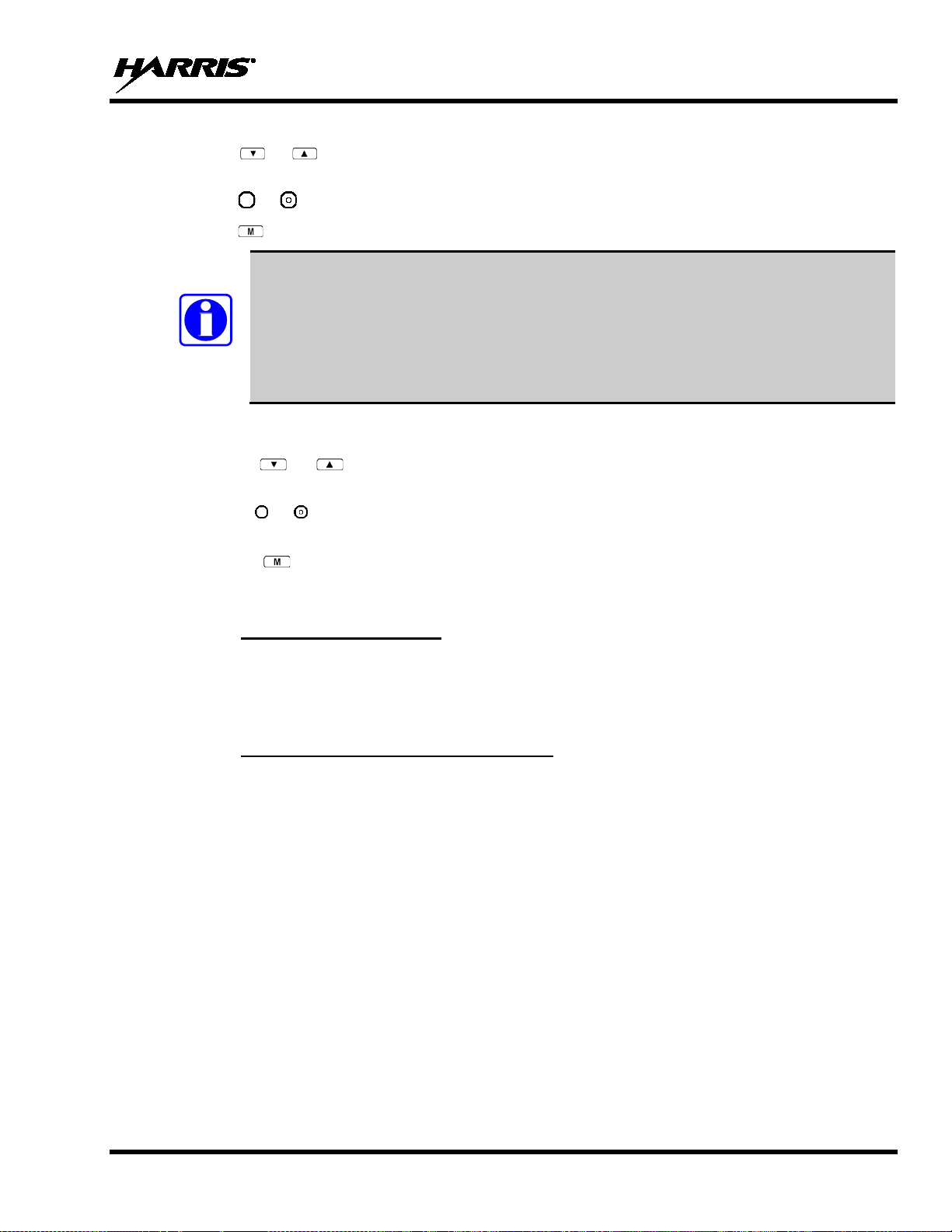
MM-008212-001, Rev. L
are saved
NOTE
9.20.3.1 Changing Scan Priority
1. Press or un til “Priority1” or “Priority2” appears in the display (Priority1 group has higher
priority than the Priorty2 group).
2. Press or until the desired talk group is displayed.
3. Press to select and activate the selection. The radio automatically returns to the Dwell Display.
• Changing the priority of a listen group does not change your talk group.
• Priority can be set for six talk groups (Priority1, Priority2, and up to four Priority 3),
but only in the selected profile.
• If the save settings is configured for the radio, scanning priority settings
when the radio is turned off. Otherwi se, they are reset to the default values when the
radio is turned off.
9.20.3.2 Changing Scan Priority 3 Talk Groups
1. Use the or buttons to scroll through the menu choices until “Priority 3” appears in the
display.
2. Use the or keys to scroll through the list of talk groups, if any, until the user group you want to
set as Priority 3 appears in the display.
3. Press the key to select a Priority 3 talk group.
4. “<” appears next to the Priority 3 talk group.
9.20.4 Scan Mode A/B Switch
The A/B switch can be configured to toggle Scan Mode On/Off.
If the Scan mode icon is On; either the Normal or Fixed Scan modes are enabled, depending on
programming. If the Scan mode icon is not displayed, Scan mode is set to No Scan.
9.20.5 Scan Mode Quick Key (P5470 Only)
Press 3# to toggle Scan Mode On/Off.
If the Scan mode icon is On; either the Normal or Fixed Scan modes are enabled, depending on
programming. If the Scan mode icon is not displayed, Scan mode is set to No Scan.
9.21 MAKING SE LECTI VE CA LL S
Selective calling is the capability for two voice radio units to obtain and use an independent talk path for a
unit-to-unit call. A properly equipped radio can initiate a selective call to any radio in the system that is
also programmed for selective calls.
In the OpenSky system, a radio can be co nfigu red to in itiate sele cti ve calls th roug h a pre-programmed list
in memory called a speed dial list. Alternatively, a properly equipped radio can initiate a selective call to
any radio in the system by enterin g the ten-digit User ID (similar to a telephone number) of the target
radio. Some radios are configured to only receive (not initiate) selective calls.
45
Page 46

MM-008212-001, Rev. L
Selective calls are terminated if an emergency is declared. The network limits selective
STATUS MESSAGE
DEFINITION
Busy
Peer is involved in another selective/PSTN call.
Selective/PSTN call was terminated for unknown
reason.
an unspecified network error.
Peer or this user declined request to establish
selective/PSTN call.
Unavailable
Peer cannot be reached for selective/PSTN call.
Calling
Calling peer (i.e., for selective or PSTN calls).
Connecting
Establishing selective/PSTN call with peer.
Hangup
Peer or this user terminated selective/PSTN call.
Lim 10 min
Selective/PSTN call limited to 10 minutes.
before limit is reached (shown for 5 seconds).
Sel Call
Selective call is active.
NOTE
NOTE
calls to ten (10) minutes maximum.
If a Selective Call is attempted without registration, “No Priv” is displayed.
9.21.1 Manually Dialing a Selective Call (P5370 Only)
1. Enter *8, the User ID number of the user being called, and the # key (no dashes or spaces). Note that
this feature must be enabled by the administrator.
*8<destination user id>#
A shortened User ID number can be dialed using the following guidelines:
• If the radio being called is in the same region and agency – enter only the last four digits.
• If the radio being called is in the same region, but a different agency – enter the last seven digits.
• If the radio being called is in another region or if the area is unknown – enter all ten digits.
2. Press PTT (and release) to ring the other user.
The ring tone is sounded.
If the other user accepts the call, the called user’s alias will appear in initiating caller’s d isplay. The
two are now in a unit-to-unit call until one ends the call, the call is terminated due to an initiated
emergency, or the maximum time limit of ten ( 10) minutes is reached.
Table 9-8 lists and defines the messages that are displayed by the radio during a selective call.
Table 9-8: Status of Selective Call
Disconnect
Network Err
Reject
Timing Out
Selective/PSTN call cannot continue because of
Selective/PSTN call has 10 seconds remaining
46
Page 47
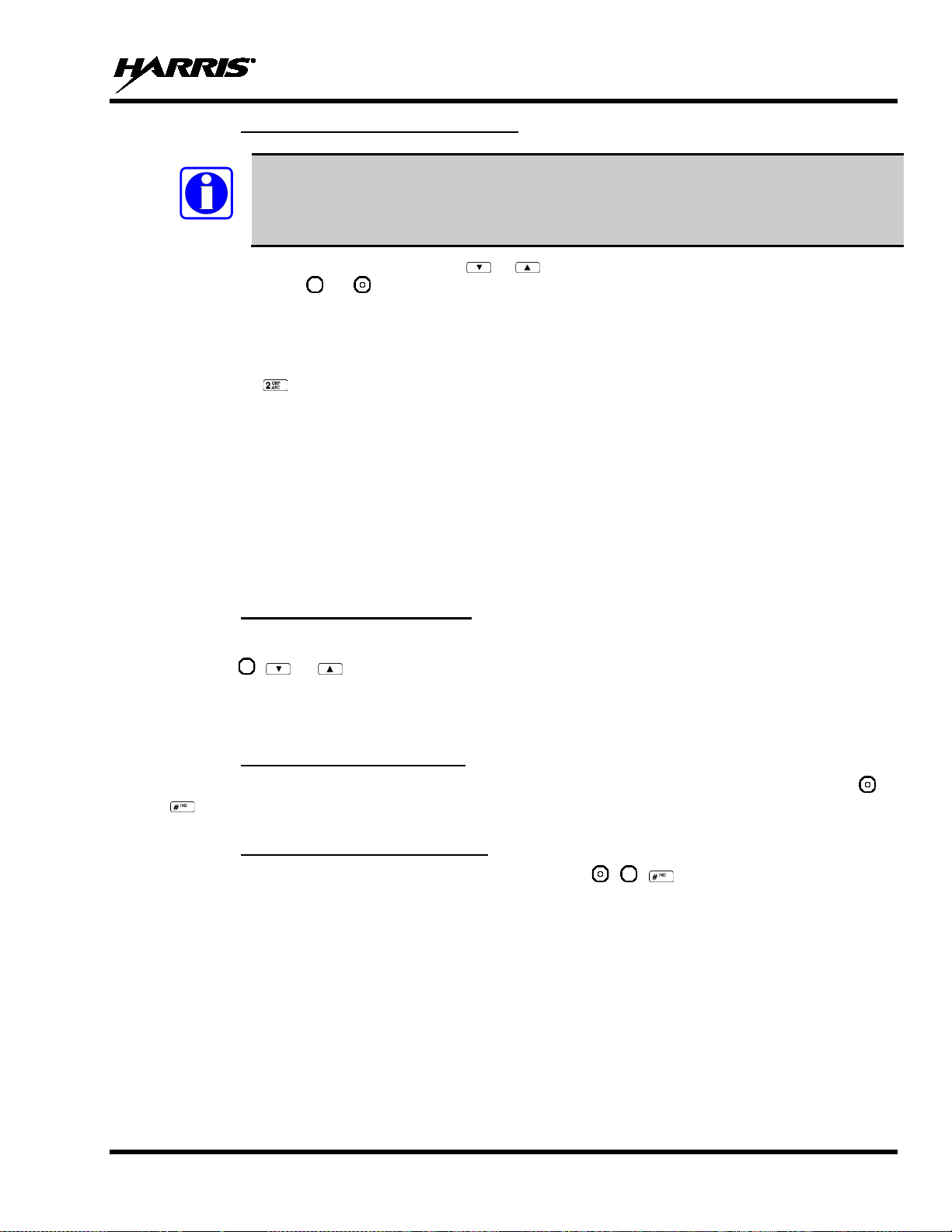
MM-008212-001, Rev. L
NOTE
9.21.2 Selective Call Using Speed Dial
Speed dial numbers are defined and provisioned by the OpenSky network admin istrator and
cannot be manually entered into the radio by the user. Contact the administrator if changes
to the speed dial list are required.
1. Scroll through the Menu options using or until “Speed Dial” appears in the second line of the
display. Using or , scroll through the pre-programmed speed-dial numbers until the desired
number appears in the display and press the PTT button.
OR
2. Press and hold a key associated with a given number for more than three seconds. For example, press
and hold to open the Speed Dial Menu and display the number assigned to that key in the speed
dial list. Press the PTT button.
A ring tone is sounded.
If the other user accepts the call, the c alled user’s alias will appear in in itiating caller’s display. The two
are now in a unit-to-unit call until one ends the call, or the call is terminated due to an initiated
emergency.
If the called radio is involved in another selective call, “BUSY” will appear on the second line of the
display. “Unavailable” is displayed when the cal l has not been answered after a 1 minu te timeo ut or when
the other party is not registered on the network.
9.21.3 Accepting a Selective Call
1. The radio will ring (like a telephone), indicating you are receiving a Selective Call.
2. Press ,
, or to accept the incoming selective call.
3. “CONNECT” will appear in the display, followed by “Lim 10 Min.” “SEL CALL” and the alias of
the caller appear in the display once the call is established.
9.21.4 Rejecting a Selective Call
When a Selective Call is being received (the radio is ringing), you can reject the call by pressing or
. The call will be rejected and “Reject” appears on the callers display.
9.21.5 Terminating a Selective Call
Terminate a Selective Call (call must be active) by pressing , , , or by turning the Voice Group
Selector Control knob. “HANGUP” will appear in the display followed by the active talk group.
9.22 SELECTIVE ALER TS
Selective alert messaging is an OTP feat ure that allows one of up to eight (8) pre-programmed (canned)
text messages to be sent from one radio to another. The sender specifies a destination (receiving) radio,
selects one of the pre-programmed text messages, and then transmits it to the destination radio. The
message delivery system adds sender and time-of-day information and forwards the message to the
destination (receiving) radio. The sending radio receives a brief message noting the status of the
transmission.
47
Page 48

MM-008212-001, Rev. L
Alert Sent
Alert message successfully sent to target.
Delivered
Alert message passed to network.
Delivering
Delivering alert message to target.
New alert
New alert message received.
No alerts
No alerts are available.
VNIC congested and cannot deliver message at
the current time.
Dest Down
Destination home VNIC down.
Destination is either non-responsive or does not
care to respond.
Inv Option
Distribution option is invalid.
Not Reg
Destination is not registered.
Partial
Not all destination ESN instances reachable.
Unauthorized service function; initiator is not
authorized to send the selected service message.
Unknown Msg
Unknown status received from VNIC.
Unreachable
Alert destination cannot be reached.
Received messages are stored in th e radio until deleted or until the radio is reb ooted. Received messag es
do not survive a reboot.
9.22.1 Defining Messages
All selective alert messages are pre-defined. The messages are programmed and provisioned remotely by
your OpenSky system administrator. The radio user cannot create selective alert message content. The
entire selective alert message, including the abbreviation, can be up to 99 characters long.
Table 9-9 lists and defines the messages that may be displayed by the radio during a Selective Al er t.
Table 9-9: Status of Selective Alert Messages
STATUS MESSAGE DEFINITION
Busy
Ignored
Unauth Alrt
9.22.2 Sending a Message
The sending process has three steps. First select the destination radio’s User ID, then select the alert
message, and finally send the message.
9.22.2.1 Selecting a Destination Using the Keypad (P5370 Only)
1. Using the keypad, enter *7.
At the “AlertDst” prompt, enter the full User ID of th e unit t o send th e message. A sho rtened User I D
number can be dialed using the following guidelines:
• If the radio being called is in the same region and agency – enter only the last four digits.
• If the radio being called is in the same region, but a different agency – enter the last seven digits.
• If the radio being called is in another region or if the area is unknown – enter all ten digits.
2. Press to activate the selection.
3. Use , , , or to scroll through the available messages until the desired message is
displayed.
4. Press or to send the message.
48
Page 49

MM-008212-001, Rev. L
NOTE
5. Observe Status Messages (Table 9-9) to ensure proper delivery.
9.22.2.2 Selecting a Destination Using the Menu
1. Using or , scroll through the menu until “AlertDst” (Alert Destination) appears.
2. Use or to scroll through the list o f User IDs until the desired destination i s displayed and press
.
3. Use or to scroll through the availabl e messages until the desired message is displayed.
4. Press to send the message.
5. Observe Status Messages (Table 9-9) to ensure proper delivery.
9.22.3 Receiving a Message
When a selective alert message is receiv ed by a radio, a four-beep tone is heard. The tone is heard only
once, but the message “NEWALRT” alt ernates with the talk g roup on the main disp lay. Up to 8 received
messages can be stored. If a ninth messag e is received, the first (ol dest) message is automatical ly deleted
to make room for the new message.
Received messages are displayed with the time and source information.
To display a Selective Alert Message:
1. Using or
, scroll through the menu items until “Alerts Rcvd” appears. The ol dest message is
displayed and scrolls across the top lin e of the display.
2. The message includes the time, the User ID, and alias of the sender along with the message.
3. To view the next message, press or to go forward or backwards.
9.22.4 Deleting a Selective Alert Message
1. Display the message.
2. Press and or to select Y or N.
3. At the “Delete? Y” prompt, press . Th e message is deleted.
Received messages cannot be saved.
9.23 INTERCONNECT CALLS (P5370 ONLY)
9.23.1 Making Interconnect Calls
1. Using the keypad, enter *9, followed by the telephone number being called, and the # key (no dashes
or spaces).
*9<telephone number>#
Wait a couple of seconds and press and release the PTT button to initiate the call. An initial ring tone
will sound to indicate signal call initiation. Once the gateway picks up the call, the ring tone will
change. Press and hold the PTT and talk normally, then release the PTT to listen.
2. To hang up the call, press
or the key.
49
Page 50

MM-008212-001, Rev. L
microphone goes hot for a
The emergency behavior for the selected profile is configured by the network
administrator. This determines whether pressing the Emergency button sends an
sent with an Emergency Call.
NOTE
NOTE
9.23.2 Receiving Interconnect Calls
Press , , or to accept an incoming interconnect call.
9.24 EMERGENCY COMMUNICATIONS
The P5300 portable radio is capable of sending an emergency alert and making emergency calls on the
network. The OpenSky system handles emergency calls with the highest priority, allowing you or the
people you serve to get needed help.
Emergency call and alert capability for a profile is configured by the system administrator.
The radio that initiates an emergency alert emits a signal of 3 distinct beeps that only goes
to the dispatch console.
Table 9-10: Emergency Calls vs. Emergency Alerts
EMERGENCY ALERT EMERGENCY CALL
An Emergency Alert message is s ent to the dispat cher con sole. Al l peers (radios
and consoles) and the dispatch cons ole play the emergency tone whenever an
An Emergency Alert message is sent
to the dispatcher console. The disp atch
console plays an emergency tone
when it receives the message.
emergency call is detected. An emer gency tone plays for each ne w emergency,
or when a profile is changed, (assuming there is an emergency on one of the talk
groups for the new profile).
If the orange LED is flashing rapidly, t he radio is receiving an emergenc y call. If
the LED is flashing every ½ s econd, the selec ted talk group is in the emer gency
state (although not transmittin g). If the selected talk group is in the emergency
state, an asterisk displays next to the talk group name.
No emergency audio (voice)
transmission (hot-mic) capability
available (per programming by s ystem
administrator)
In addition to the Emergency Alert signal, the
predetermined length of time to all ow for emergency audio (voic e) transmission.
The radio declaring the emergency has channel access priority. Note that the
User can also use the PTT af ter the pre-determine d hot-mic audio transm ission,
or during to extend the initial hot-mic audio transmission.
9.24.1 Declaring an Emergency Call or Alert
1. Press the red emergency button on the radio to enter emergency mode.
Emergency Call or just an Emergency Alert. An Emergency Alert is always part of and
If the active profile of the unit initiating the emergency is configured to Emergency Alert, the threebeep emergency alert signal is sent only to t he dispatcher console.
If the active profile of the unit initiating the emergency is configured to Emergency Call, the threebeep emergency alert signal is sen t to the dispatcher console and to all other radios within the selected
talk group. The default emergency talk group becomes the selected talk group. The display will
alternate between the emergency talk group name and “EMERGENCY” to indicate that the
emergency has been initiated.
50
Page 51

MM-008212-001, Rev. L
administrator to ensure that your radio is configured with the
NOTE
NOTE
NOTE
NOTE
2. The microphone is hot (open mic) for a programmed amount of time in order to send your voice out
on the emergency talk group. All of the radios in the emergency talk group hear your call and see the
emergency talk group displayed on their radio.
If the attempt is unsuccessful, “E-PEND” flashes periodically and a retry is queued for 10 seconds. If
unsuccessful because of lost sync, ret ry occu rs i mmed iatel y upon reacqu irin g sy n c. On each r etry attempt,
radio temporarily displays “E-RETRY.” This process repeats until the emergency is successfully
declared.
9.24.2 Receiving an Emergency Call
Initially, when receiving an emergency call, the radio sounds the emergency tone (three short highpitched tones).
The radio will flash “EMERGENCY” and display the alias of the user th at trig gered the e merg ency or the
alias of the talk group (if the incoming talk group is the selected talk group of the receiving radio).
With “None,” only the emergency tone is heard, not the initial open mic transmission.
To dismiss or ignore the emergency, refer to Section 9.24.3.
9.24.3 Dismissing an Emergency
The “Dismissing an Emergency” funct ion allows you to “ignore” an emergency declared by another user.
An emergency is dismissed for a configurable amount of time (default = 5 minutes).
1. After receiving an emergency call, press or until you see “EmgDismiss.”
2. Press to toggle “<” on (dismiss) and off. This works in similar fashion to the lock out menu.
The emergency dismiss timer is cleared when the emergency is cleared.
9.24.4 Clearing an Emergency Call or Alert
Check with your system
ability to clear an emergency.
1. To clear an emergency, press and hold . While holding , press the emergency bu tton. Release
both buttons when the “emergency cleared” tone sounds.
2. The radio returns to your default selected talk group. The “EMERGENCY” display is removed from
the main screen.
If the radio is in stealth mode, cl earing the emergency will cau se the radio to exit Stealth
Mode.
51
Page 52

MM-008212-001, Rev. L
9.25 STATUS MESSAGES
If enabled via programming, the radio can transmit a pre-programmed status message. Section 9.25.1
describes how to send a status mess age via the keypad and Section 9.25.2 describes how to send a status
message via the menu.
9.25.1 Send Status Message via the Keypad (System Model Radios O nly)
1. Press *2 <0…9> # on the keypad.
2. A Status message can be associated with each key (0 – 9). This text is displayed on the first line of the
display when the key is pressed until another key is pressed.
• If no messages have been configured, “No Messages” is displayed.
• If a message is not assigned to a key, “No Entry” is displayed for the keypad sequence.
• You can press multiple keys to select the desired Status message.
3. The # key terminates the keypad sequence and sends the currently selected status message. If no
messages have been configured or no message is associated with the key, no message is sent an d an
error tone is played.
Press the * key to cancel the keypad sequence.
9.25.2 Send Status Message via the Menu
1. Press or until “Status Msg” appears and press . If no messages have been configured,
“No Messages” is displayed.
2. Scroll through the available mess ages using or . The configured Status message is displayed on
3. Press the button to send the currently selected message. If no messages have been configured, no
Press or
st
line of the display.
the 1
message is sent and an error tone sounds.
to cancel status message selection.
9.26 REQUEST TO TALK (RTT) MESSAGES
If enabled via programming, the RTT message feature allows you to send either a short service message
to the VNIC. Section 9.26.1 describes how to send an RTT message via the keypad (P5370) and Section
9.26.2 describes how to sen d an RTT message via the menu. Note that only o ne RTT message can be
programmed into the radio.
9.26.1 Send RTT Message via the Keypad (System Model Radios Onl y)
1. Press *5 <0…9> # on the keypad. The key associated with the RTT message (0-9) is configured via
programming.
2. This message is displayed on the first line of the display when the key is pressed until another key is
pressed.
• If no message has been configured, “No Message” is displayed.
• If a message is not assigned to the key, “No Entry” is displayed for the keypad sequence.
3. The # key terminates the keypad sequence and sends the currently selected RTT message. If no
message has been configured or no message is associat ed with the key, no message is sent and an
error tone is played.
52
Press the * key to cancel the keypad sequence.
Page 53

MM-008212-001, Rev. L
receiver’s data is expired (30 minutes or more) or unavailable, the
NOTE
9.26.2 Send RTT Message via the Menu
1. Press or until “RTT Msg” appears an d press . If no message has been configured, “No
Message” is displayed.
st
2. Use or to select the mes sage. The configured RTT message is d isplayed on the 1
display.
3. Press the button to send the selected message. If no message has been configured, no message is
sent and an error tone sounds.
line of the
Press or
to cancel RTT message selection.
9.27 SITE LOCK
Users may need to select the site in cases wher e netwo rk co mmunicatio ns are do wn. Th e Site Lo ck menu
allows a user to manually roam to a specific site. T he sites in the menu are populated with the current
site, adjacent sites, and node 2 sites. The menu allows the user to select a particular site based o n the Site
Name. Once selected, the radio will randomly pick a channel at the site that is identified as operational
and attempt to attach to it.
If the channel is not available, the radio attempts to attach to the next channel in the channel list for the
site until it has attempted every channel at the sit e. If no channels are available, the radio plays a “Site
Not Found” tone and displays “SiteUnavail” on the second line of the Site Lock menu. The radio reverts
to its normal roaming functionality.
If the radio does find a valid channel on the site, it attaches to it, plays a “Site Found” tone, displays
“SiteAvail” on the second line of the Site Lock menu for 2 seconds, and then reverts to the Dwell menu.
9.28 GPS COORDINATES
The radio’s current latitude and longitude coordinates may be displayed using the “GPS” menu. The
following procedure assumes a GPS anten na is connected to t he radio and it is receivi ng adequate signals
from GPS satellites.
1. Press or un til the “GPS” menu appears in the display. Current GPS coordinate latitud e and
longitude data continuously scrolls in the top line of the display in a degrees:minutes:seconds format.
2. Press or
to change to another menu.
If the internal GPS
radio uses the serving base station ’s coo rdinates [GP S (S ite) is di splay ed]. The G PS M enu
will also indicate if the data is aged (2 minutes or more) [GPS (Aged) is displayed].
9.29 V-TAC OPERATION
9.29.1 Extended Coverage Modes (XCOV, XCOV-TG, and XCOV-PROF)
In addition to all standard portable radio operating capabilities, Extended Coverage adds the V-TAC’s
bridging (vehicular repeat) function ality for accessing the OpenSky radio network. Each portable radio
connected to the V-TAC using Extended Coverage is considered a “client” on the V-TAC. Extended
Coverage benefits portable radio users since it allows them to get network connectivity using the
V-TAC’s higher transmit output power and better antenna system.
53
Page 54

MM-008212-001, Rev. L
The V-TAC supports three Extended Coverage modes: Extended Coverage for individual users (XCOV),
Extended Coverage for a talk group (XCOV-TG), Profile Extended Coverage (XCOV -PROF). Typically,
Extended Coverage is used after the vehicle’s operator has exited the vehicle with a portable radio unit
and the portable unit requires this bridging functionality to access the OpenSky radio network.
The V-TAC takes advantage of OpenSky’s T DMA capability to eliminate interference between its lo cal
and network radio links when operating in an Extended Coverage mode, an undesirable characteristic of
many traditional vehicular repeater syst ems. Because the V-TAC employs this technology, interference
on the network and local radio links is minimized.
A V-TAC in Ex tended Coverage mode sends its alias to cli ents. The alias is displayed in the second line
of the dwell menu of the client, (“VA <alias>”). The client must be connected to a V-TAC running
version OTP14.4 or for the V-TAC to provide the alias to the client. If the client is connected to a V-TAC
running version OTP14.3.1 or earlier, the client displays “VA None.”
9.29.2 Change between Extended Coverage Modes
By default, the specific Extended Coverage mode utilized is determined by settings programmed into the
V-TAC and portable radios from the system administrator or radio installation personnel. These
programmed settings determine which Extended Coverage mode the V-TAC and radios normally use and
determine the access method employ ed by a portable radio to connect to the V-TAC. After these settings
are programmed to the V-TAC and portable radios, each must be rebooted (powered off and then back
on) before the change takes effect.
See the following sections for instructions on how to override this setting manually. Note that the override
is only successful if the V-TAC operating mode matches the manually selected portable V-TAC mode.
9.29.3 Radio Limitations Using Extended Coverage M odes
Connecting a portable radio to a V-TAC introduces minor functional limitations. See the following
sections for a listing.
9.29.3.1 Limitations Using XCOV, XCOV-TG, and XCOV-PROF
Portable radios connected to the V-TAC using any of the Extended Coverage Modes, XCO V, XCOV -TG,
or XCOV-PROF, will not channel-scan unless they lose radio frequency contact with the V-TAC. If
manually enabled, radios will not scan netwo r k channels.
9.29.3.2 Limitations Using XCOV-TG
The following portable radio keypad functions are disabled when the radio is connected to the V-TAC
using the XCOV-TG mode: log-off, manual log in, alerts, selectiv e calls, PSTN calls, and speed dial c alls,
SOI mode, RTT.
The following portable radio menus are disabled when the radio is connected to the V-TAC using the
XCOV-TG mode: alert destination, alert message, alert received, channel, speed dial, priority 1 talk
group, priority 2 talk group, priority 3 talk group, RTT, Status message, site lock and scan mode. In
addition, the user cannot change talk group or profile.
54
9.29.3.3 Limitations Using XCOV-PROF
The following portable radio keypad functions are disabled when the radio is connected to the V-TAC
using the XCOV-PROF mode: log-off, manual log in, alerts, selective calls, PSTN calls, and speed dial
calls, SOI mode, RTT.
Page 55

MM-008212-001, Rev. L
The following portable radio menus are disabled when the radio is connected to the V-TAC using the
XCOV-TG mode: alert destination, alert message, alert received, priority 1 talk group, priority 2 talk
group, priority 3 talk group and scan mode. In addition, the user cannot change talk group or profile.
9.29.4 Use XCOV Mode
The Extended Coverage for individual users (XCOV) mode allows up to eight (8) client radios to connect
to the V-TAC. The radios have full radio functionality including selective calling and mobile data.
With the Extended Coverage for individual users’ (XCOV) mode, V-TAC configuration defines which
portable radios are permitted V-TAC access. The radio will automatically connect to a V-TAC if it
cannot find a network channel. The radio can also be manually connected to a V-TAC as indicated with
the *61# and *62# commands, each determined by the system administrator in the radio configuration.
9.29.4.1 Manually Accessing the XCOV Mode
P5370 Model Radios
1. Press *61# to manually access XCOV mode.
2. Press *60# to disconnect from XCOV mode.
All P5300 Model Radios
1. Press or until the Client Mode menu appears.
2. Press or until XCOV is displayed.
3. Press to confirm mode selection. The radio reverts to the dwell display and the V-TAC icon is
displayed.
9.29.5 Use XCOV-TG Mode
When using the XCOV-TG mode, up to thirty (30) client radios can connect to the V-TAC. However,
unlike XCOV, radios connected using XCOV-TG a re limited to communicating only on the XCOV-TG
talk group. The radio can only raise an emergency if this talk group is emergency capable. Advanced
features such as selective calling and mobile data operations are not available to the XCOV-TG connected
clients. The radio will automatically connect to a V-TAC if it cannot find a network channel.
The talk group used for XCOV-TG communications is the talk group that was selected at the V-TAC
when it entered XCOV-TG mode. Before a radio can connect to the V-TAC, the talk group must be
selected on the P5300. If this talk group is not provisioned in the radio’s personality, the radio cannot
connect to the V-TAC via the XCOV-TG mode. While connected to the V-TAC via XCOV-TG, a
different talk group or profile cannot be selected.
When a portable radio is connected to the V-TAC via XCOV-TG, the V-TAC forwards only the network
voice traffic on the XCOV-TG talk groups.
9.29.5.1 Manually Accessing the XCOV-TG Mode
For the Extended Coverage for a talk group mode (XCOV-TG), a portable radio user is granted access
and connects to the V-TAC by simply selecting the same Talk Group that the V-TAC had selected wh en
it entered the XCOV-TG mode. Contact the system administrator for questions regarding these aspects.
During XCOV-TG mode operations, the V-TAC will not disconnect portable radios connected to it. A
portable radio user must manually disconn ect from the V-TAC by pressing *60 # on the radio’s keypad.
55
Page 56

MM-008212-001, Rev. L
However, if the V-TAC is switched out o f the XCOV-TG mode, all portable radios will be automatically
disconnected from the V-TAC. The radios will continue to look for another V-TAC until manually
disconnected (*60#).
P5370 Model Radios
• Press *62# to manually access XCOV-TG mode.
• Press *60# to manually disconnect XCOV-TG mode.
All P5300 Model Radios
1. Press or until the Client Mode menu appears.
2. Press or until XCOV-TG is displayed.
3. Press to confirm mode selection. The radio reverts to the dwell display and the V-TAC icon is
displayed.
9.29.6 Using XCOV-PROF Mode
In XCOV-PROF mode, client attachment to a V-TAC is based on profile rather than talk group.
XCOV-PROF mode allows the transmission and receipt of voice calls on any talk group in the profile as
opposed to only one talk group. XCOV-PROF allows emergencies on a non-selected talk group based on
the emergency behaviors of the profile. XCOV-PROF minimizes data traffic between the client and VTAC while allowing flex ibility of voice fun ctionality. As a resul t, data services between the client and VTAC are disabled. The radio will automatically connect to a V-TAC if it cannot find a network channel.
Note the following regarding XCOV-PROF mode:
• The client profile must match the V-TAC.
• The client profile used to connect to the V-TAC must have been previously provisioned to the client
prior to connection. If the profile is not in the client’s personality, the client cannot connect to the VTAC.
• Neither the V-TAC nor a client can change the p rofile once it has entered XCOV-PROF mode. The
Profile menu will be disabled.
• Client global profiles are disabled.
9.29.6.1 Access XCOV-PROF Mode
P5370 Model Radios Only:
1. Enter the command *63 # to set the radio to use the XCOV-PROF mode.
2. Press *60 # to disconnect from the XCOV-PROF mode.
All P5300 Model Radios:
1. Press or until the Client Mode menu appears.
2. Press or until XCOV-PROF is displayed.
3. Press to confirm mode selection. Th e radio reverts to the dwell display and the V-TAC icon is
displayed.
56
Page 57

MM-008212-001, Rev. L
CAUTION
9.29.7 Use Scene-of-Incident Mode
The Scene-of-Incident mode (SOI) is user-selectable. Th e SOI mode provides a local repeater function
(V-TAC) with no network connection.
When operating in the SOI mode, the radio is disconnected from the OpenSky network.
Therefore, communications with radios and dispatch personnel on the network is not
possible.
SOI Mode, Manual Channel Entry (P5370 Model Only)
1. Press *4#.
2. The radio prompts for the channel. Enter the channel number and press to confirm channel.
3. The radio prompts for the band. Table 9-11 lists valid bands and their definitions. Enter the number
assigned for the desired frequency band and press to confirm.
4. The radio reverts to the dwell display. If accepted, you will be switched off the network, and be
communicating locally through the V-TAC.
Press *40#, *41#, or use the Client Mode menu to return to normal operation (Network Mode). The
personality and profile in use at the time th e radio entered SOI mode is restored.
SOI Mode, Manual Channel Entry (All P5300 Models)
1. Press or until the Client Mode menu appears.
2. Press or until SOI is displayed.
3. Press to confirm mode selection.
4. Press or until “Manual Select Chan” is displayed and press .
5. Press or to edit the right-most digi t and p ress to advance to the next digit. Repeat until the
desired channel is entered.
6. The radio then prompts the user to edit the band. Table 9-11 lists valid bands and their definitions.
Press or to edit the number assigned to the frequency band and press to confirm and enter
the SOI mode.
Use the Client Mode menu to return to normal operation (Network Mode). The personality and profile in
use at the time the radio entered SOI mod e is restored.
SOI Mode, Pre-Programmed Channel Selection (All P5300 Models)
1. Press or until the Client Mode menu appears.
2. Press or until SOI is displayed.
3. Press to confirm mode selection.
4. Press or scroll through a list of pre-programmed channels.
5. Press to confirm channel and enter SOI mode.
Use the Client Mode menu to return to normal operation (Network Mode). The personality and profile in
use at the time the radio entered SOI mod e is restored.
57
Page 58

MM-008212-001, Rev. L
RF BAND
RF CHANNEL NUMBER
0 = SMR
Band 0: 1-830
1 = AMPS
Band 1: 1-600
2 = BORDER
Band 2: 1-600
3 = 700 MHz Band 1
Band 3: 1-477
4 = 700 MHz Band 2
Band 4: 481-957
5 = 700 MHz Band 3
Band 5: 1-477
6 = 700 MHz Band 4
Band 6: 481-957
7 = 900 MHz
Band 7: 1-399
8 = 800 MHz Rebanded
Band 8: 1-830
Band 9: 1-6718
(Independent Separation Betwee n TX and RX)
Band 10: 1-6718
(Independent Separation Betwee n TX and RX)
11 = 400 MHz T band Temp (NYPD only)
Band 11: 1-120
14 = 700 MHz reband WB
Band 14: 1-957
15 = 700 MHz reband NB
Band 15: 1-959
Table 9-11: Band Definitions
9 = 400 MHz T band WB
10 = 400 MHz T band NB
58
Page 59

MM-008212-001, Rev. L
In the trunked environment, CC SCAN is di splayed if communication with the sy stem's
range of the trunking site. It may be necessary to move to another location or select
establish the control channel link for trunked mode
Control Channel is configurable in RPM.
NOTE
NOTE
10 EDACS AND CONVENTIONAL OPERATION
10.1 TURNING ON THE RADIO
1. Power ON the radio by rotating the POWER ON-OFF/VOLUME knob clockwise. A short alert
signal (if enabled through programming) indicates the radio is ready to use.
The radio can be programmed to require the entry of a PIN in order to operate the radio.
Check with your System Administrator if you forget your PIN. As the PIN is entered, an
asterisk is displayed for each digit. The actual value is not displayed.
2. The display shows the last selected system and group or a default system and group (depending on
programming).
3. Adjust the POWER ON-OFF/VOLUME knob to the desired volume level.
4. Select the desired system and group/channel. The display indicates the current system and
group/channel names.
5. The radio is now ready to transmit and receive calls.
control channel cannot be established. This may occur if, for examp le, the radio is out of
another trunking system to reoperations. CC SCAN is displayed on the group line until a control channel is accessed.
The length of time before the radio enters CC Scan after losing communication with the
10.2 CONTROLS
The radio features two rotary control knobs, an emergency button, and a dual position A/B switch
mounted on the top of the radio. The Push-To-Talk and two option buttons are located on the side. The
front mounted keypad has six buttons on the P5350 Scan Model and 15 buttons on the P5370 System
Model Radio.
59
Page 60

MM-008212-001, Rev. L
Applies power to and adjusts the receiver’s volume. Rotating the control clockwise
applies power to the radio. A single alert tone (if enabled through programming)
ontrol clockwise increases the volume level. Minimum volume levels
may be programmed into the radio to prevent missed calls due to a low volume setting.
While adjusting the volume the display will momentarily indicate the volume level
VOL=31
olume range is from a minimum programmed level of zero
(displayed as OFF in the display) up to 40, which is the loudest level.
position
A mechanical stop, which can limit the posit ions accessed, is shipped with the
voice group
metal base
metal base.
Replace the 16 channel ring with t he channel stop ring located at the desired channel.
metal base, tighten the set screw, an d rei nstall
the voice group selection knob.
programmed Group/System by pressing and holding for
a programmed duration. It can also be used to declare an emergency by pressing and
programmed for either
operation, but not both.
In trunked mode the
radio’s ID is transmitted upon depression of the PTT button.
s one of a number of programmable software options selected during PC
Programmable options include hi/low power settings, keypad lock,
LCD contrast, and LCD and keypad back lighting.
10.2.1 Buttons, Knobs, and Switch
The functions of the buttons, knob controls, and dual position A/B Switch vary depending on the mode of
operation. Their default functions while in EDACS/Conventional modes are discussed in the following.
Figure 10-1: Top View
POWER ON-OFF
VOLUME KNOB
SYSTEM/GROUP/
CHANNEL KNOB
Figure 10-2: Side View
Table 10-1: Buttons, Knobs, and Switch Functions
indicates the radio is operational.
Rotating the c
(i.e.,
). The v
Selects systems or group/channels (depending on programming). This is a 16rotary knob.
Note:
radio but must be installed. To install the mechanical stop, remove the
selection knob, loosen the set screw on the voice group selection knob
(using a 1.27 mm hex wrench), and remove t he voice group selection knob
Reinstall the voice group selection knob
EMERGENCY/HOME
BUTTON
Automatically selects the pre-
holding for a programmed duration. The button must be pre-
PTT BUTTON
OPTION BUTTON 1
Push-To-Talk must be pressed before voice transmissi on begins.
Activate
programming.
60
Page 61
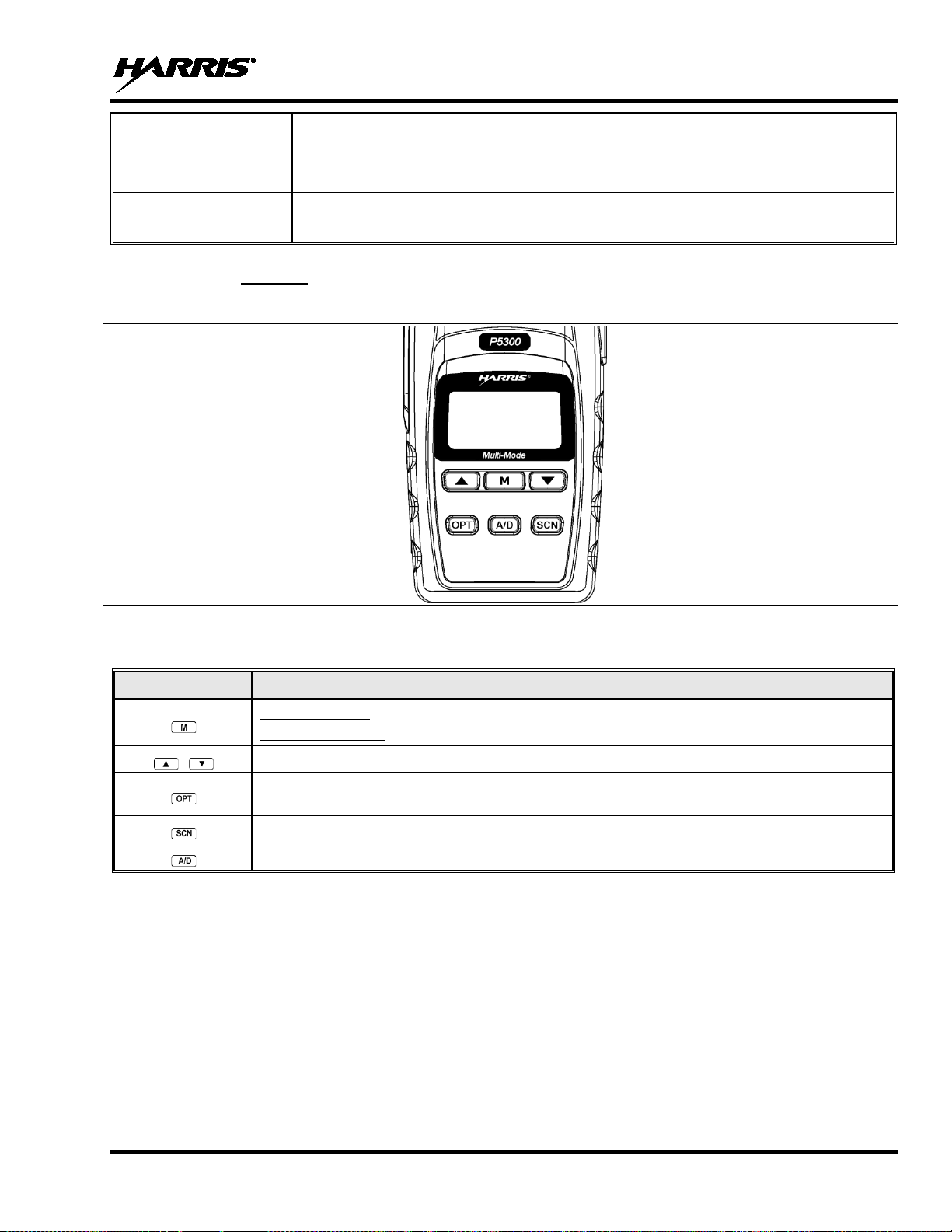
Exits the current operation (removing all displays associated with it) and returns the
In conventional mode, allows the user to monitor the channel for activity.
selected
during PC programming.
KEY
FUNCTION
CLEAR/MONITOR
BUTTON
MM-008212-001, Rev. L
radio to the idle display. Terminates individual and telephone interconnect calls.
A/B SWITCH
10.2.2 Keypad
The functions of the keys are described in Table 10-2 and Table 10-3 and the following subsections.
Can be pre-programmed to switch between two available software options
Figure 10-3: P5350 Scan Model Front Panel
Table 10-2: P5300 Scan Model Keypad Functions
Primary Function: Accesses the pre-stored menu.
Secondary Function: Activates a selected item within the menu. This is similar to an “Enter” key.
Scrolls thru available menu items.
Activates one of any programmable software options selected during the PC programming,
including: high/low TX power and talkaround.
Toggles SCAN operation ON and OFF.
Adds/Deletes selected groups or channels from SCAN list of the currently selected system.
61
Page 62

MM-008212-001, Rev. L
Primary Function: Accesses the pre-stored menu.
Primary Function: Allows the user to scroll through available systems, groups, or channels,
Secondary Function: Changes the selection for an item within a list.
9, *, and #
Figure 10-4: P5370 System Model Front Panel
Table 10-3: P5300 System Model Keypad Functions
KEY FUNCTION
Secondary Function: Activates a s el ec ted item within the menu. This is similar to an “Enter” key.
depending on personality program ming.
Primary Function: Refer to the separate key definitions within this table.
Secondary Function: These keys function much as a typical DTMF telephone pad 0-
keys; and are used to place telephone interconnect and individual (unit -to-unit) calls.
Selects a specific system. I f the rot ary kn ob is use d to sel ect the system and m ore than 16 syst ems
are programmed in the radio, the key is used to select additional banks (groupings) of systems.
Selects a specific group.
Turns the Scan operation ON and OFF.
Not applicable.
Adds groups or channels from the currently selected system to the Scan list.
Status. Access to the status list (0-9). The Status key permits the transmission of a pre-programmed
status message to an EDACS site.
Message. Access to the message list (0-9). The Message key permits the transmissi on of a pre-
programmed message to an EDACS site.
Deletes selected groups or channels of the currently selected system from the Scan list.
Inverts display – Toggle normal/invert.
Places telephone interconnect calls.
Initiates individual calls.
62
Page 63

10.3 DISPLAY
The radio Display is made up of 3 lines (see Figure 10-5). Lines 1 and 2 contain eight alphanumeric
character blocks and are used primarily to display system and group names. Line 1 also displays radio
status messages. The 3rd line is used pri marily to display radio status icons. All three lines are used to
display menu options when in the menu mode. If programmed, the display backlighting will illuminate
upon power up or when radio controls are operated.
MM-008212-001, Rev. L
Figure 10-5: Radio Display
Table 10-4 describes the icons displayed by the radio during operation.
Table 10-4: Status Icons Descriptions
STATUS ICON DESCRIPTIONS
Steady – During all radio transmissions.
Steady – “Busy” transmitting or receiving.
Flashing – Call is queued.
Steady – T99 Mode enabled.
Steady – Channel Guard enabled. If icon is not visible – Channel Guard is disabled.
Steady – Trunked system in Failsoft™ mode.
Steady – Transmit at low power.
If icon is not visible – Transmit at high power.
Steady – Indicates the current channel is set up as a ProVoice channel.
Steady – Indicates the current channel is set up as an analog channel.
Animated (rotates clockwise) – Scan mode enabled.
If icon is not visible – Scan is disabled.
63
Page 64

MM-008212-001, Rev. L
STATUS ICON DESCRIPTIONS
Steady – Group or channel in scan list.
Steady – Priority 2 group or channel.
Steady – Priority 1 group or channel.
Steady – Special call mode (individual or telephone).
Steady – Battery charge indicator.
Flashing – Low battery indicator.
Flashing - Acquiring GPS satellites.
Steady - GPS satellites have been acquired.
Figure 10-6: Full Cycle Battery Charge Indicator
The battery charge indicators illustr ate approximate lev el only, based on battery voltag e. Refer to Figure
10-6.
64
Page 65

MM-008212-001, Rev. L
QUEUED
SYS BUSY
Indicates the system is busy, no channels are currently available, the
queue is full, or an individual call is being attempted to a radio that is
DENIED
CC SCAN
WA SCAN
Indicates the radio has entered the Wide Area Sc an mode to search for a
10.4 TRI-COLOR L ED
The Tri-Color LED changes color to indicate radio status and is visible from both the front and top of the
radio (see Figure 10-7). The P5300 utilizes two of the three colors of the LED and the status they
represent are defined below.
Figure 10-7: Tri-Color LED
Green: Receiving
Red: Transmitting
If the LED is flashing rapidly, the radio is receivin g an emergency call. If the LED is
flashing every ½ second, the selected ta lk group is in the emergency state (although not
transmitting). If the selected talk group is in the emergency state, an asterisk will be
displayed next to the talk group name.
10.5 STATUS MESSAGES
During radio operation, various radio Status Messages can be displayed. The messages are described
below.
MESSAGE
NAME DESCRIPTION
Call Queued Indicates the syst em has placed the call in a request queue.
System Busy
currently transmitting.
Call Denied Indicates the radio or talkgroup is not authorized to operate on the selected
system and/or talkgroup.
Control
Channel Scan
Indicates the control channel is lost and the radio has entered the Control
Channel Scan mode to search for the control channel (usually out of range
indication).
Wide Area
Scan
new system (if enabled through programming).
65
Page 66

MM-008212-001, Rev. L
SYSC ON
SYSC OFF
LOW BATT
voltage has dropped to the point to where the radio is no longer
able to transmit. The radio will still receive calls until the battery is
discharged beyond the point of operation at which time the radio
RXEMER
Indicates an emergency call is being received. This message will be
TXEMER
Indicates an emergency call has been transmitted on this radio. This
VOL=31
WHC
Indicates an individual call has been received, but not responded to. The
indicator turns OFF if the individual call mode is entered, the system is
UNKNOWN
only)
or
MESSAGE
NAME DESCRIPTION
System Scan
Features On
System Scan
Features Off
Low Battery Battery
Receive
Emergency
Transmit
Emergency
Volume Level In dicates the current volume level. The vol ume level display ranges from
Who Has
Called
Unknown ID Indicates an individual call is being received from an unknown ID.
Indicates the System Scan features are enabled.
Indicates the System Scan features are disabled.
automatically shuts down.
flashing on line two.
message will be flashing on line two.
OFF (silent) to 40 (loudest).
changed, or the radio is turned off and then on again.
10.6 ERROR MESSAGES
If either of the Error Messages shown below is displayed, the radio is programmed incorrectly or needs
servicing.
DSP ERR
ERR=XXXX
(PowerUp
Where xxxx is the error code and DSP ERR or DIG V ERR is the message.
DIG V x
ERR x
66
Page 67

MM-008212-001, Rev. L
Call Originate
Call Queued
Autokey
System Busy
Call Denied
Carrier Control Timer
Low Battery
TX Low Battery Alert
10.7 ALERT TONES
The P5300 radio provides audible Alert Tones or “beeps” to indicate the various operating conditions (see
Table 10-5).
NAME TONE DESCRIPTION
Table 10-5: Alert Tones
one short mid-pitched
one high-pitched
one mid-pitched
three low-pitched
one low-pitched
five high-pitched / one long low-pitched
one low-pitched / one short mid-pitched
one low-pitched
10.8 VOICE ANNUNCIATION
When enabled via programming, the Voice Annunciation feature provides audible feedback for various
radio operations. The radio can be programmed to play an audio message for any or all of the following.
This message can be a pre-recorded (canned) message or a user-recorded message.
• Channel changes
• System changes
• Encryption On/Off
OK to talk after pressing the push-to-talk b utton
Call queued for processing
Queued call received channel as signment
System busy or unable to complete call
Radio is not authorized on the system or group
PTT depressed for maximum length of t ime
Low battery
After PTT - battery too low to transmit
• Noise Cancellation On/Off
• Scan On/Off
• Talkaround On/Off
For more information on configuring the radio for Voice Annunciation, refer to the Voice Annunciation
Feature manual, 14221-7200-6110.
67
Page 68

MM-008212-001, Rev. L
METHOD 1:
From the control knob: If system
selection is programmed to the
SYSTEM/GROUP/CHANNEL SELECTION control knob, select a system by turning
the knob to the desired system
The display registers the
new system
button can be programmed to provide
access to a “2
bank” of 16 system/zone number positions (17-32).
METHOD 2:
From the keypad: If system
selection is programmed as the primary function of
to scroll through the system
list. The display registers the new system name on line one.
METHOD 3:
(
select
mode. Press the numeric key, which is mapped to the
The
radio will move to the selected system.
METHOD 1:
From the control knob: If group selection is programmed to the Voice group selection
knob
to the desired group
number position. The display registers the new group name on line two. If the knob is
moved to a position greater than the number of programmed groups, the highest
programmed group will remain selected . The button can be programmed to provide
access to a “2
bank” of 16 group number positions (17-32).
METHOD 2:
From keypad: If group selection is programmed as the primary function of
select a group by pressing
to scroll through the group list. The display
registers the new group name on line two.
METHOD 3:
to enter the group select mode.
Press the numeric key mapped to the desired gr oup. Press
The radio will move to
the selected group.
NOTE
10.9 SYSTEM/ZONE SELECTION
/zone name on line one. The
nd
and , select a system/zone by pressing or
P5370 model radios only) Direct Access: Press to enter the system/zone
If system/zone selection is programmed to the SYSTEM/GROUP/CHANNEL knob,
direct access to systems will not be available. Pressing or will scroll through
different sets of 16 systems/zones each (banks) if more than 16 systems/zones are
programmed into the radio. T he systems/zones within each bank are then se lectable
via the Voice group selection knob as described previously in METHOD 1.
Example:
System: 1 = North Group: 1 = Group 1
2 = South 2 = Group 2
3 = East 3 = Group 3
4 = West 4 = Group 4
/zone
/zone number position (1-16).
/zone
desired system. Press .
1. Press . (South is the currently selected system.)
2. Press . (Press 4 to select “West” system.)
3. Press . (West is the newly selected sy stem.)
10.10 GROUP/CHANNEL SELECTION
Several methods can be used to select a new group or channel.
, select a group by turning the Voice group selection knob
nd
or
(P5370 model radios only) Direct Access: Press
In trunked mode, press PTT button and speak normally while holding the microphone approximately two
inches from your mouth.
68
and
.
Page 69

MM-008212-001, Rev. L
In conventional mode, press the Monitor/Clear button briefly. If audio is heard or is illuminated, then
the channel is busy. Wait till the channel become available and press the PTT button and speak normally
while holding the microphone approximately two inches from your mouth.
10.11 MODIFY SCAN LIST
10.11.1 P5370 Model
1. Press to toggle scan OFF and verify is not displayed.
2. Select group or channel.
3. Press once to remove group or channel from list.
4. Press once to add as a normal group or channel.
5. Press twice to add as a Priority 2 group.
6. Press three times to add as a Priority 1 group.
7. Press to re-start scanning.
10.11.2 P5350 Model
1. Press to toggle scan OFF and verify is not displayed.
2. Select group or channel.
3. Press once to remove group or channel from the list.
4. Press once to add as a normal group or channel.
5. Press twice to add as a Priority 2 group.
6. Press three times to add as a Priority 1 group.
7. Press to re-start scanning.
10.12 BACKLIGHT ON/OFF
1. Press to access the menu.
2. Press or
to scroll through menu until “BCKLGHT” appears.
3. Press to select Backlight menu.
4. Press or
to toggle backlight ON and OFF.
5. Press to select new backlight setting.
10.13 CONTRAST ADJUST
1. Press to access the menu.
2. Press or
to scroll through menu until “CONTRAST” appears.
3. Press to select Contrast menu.
4. Press or
to adjust contrast setting from 1 - 4.
5. Press to select new contrast setting.
69
Page 70

MM-008212-001, Rev. L
10.14 DECLARING AN EMERGENCY
1. Press and hold the red Emergency/Home button (the length of time is programmable; check with the
system administrator).
2. *TXEMER* will flash in the display, plus and will be displayed. After 2-3 seconds the
transmit icon will turn off.
3. *TXEMER* and will remain until the emergency is cleared.
4. Press the PTT and will reappear.
5. Release PTT when the transmission is co mplete.
10.15 LOCK/UNLOCK THE KEYPAD
1. Press and hold the button.
2. Within 1 second, press the button on the side of the radio.
10.16 HIGH/LOW POWER ADJUSTME NT
Transmit power adjustment is possible if enabled through programming. Within conventional systems,
transmit power is adjustable on a per chan nel basis. Within EDACS trunking systems, tran smit power is
adjustable on a per system basis.
There are two ways to toggle between high and low power, described in Sections 10.16.1 and 10.16.2.
10.16.1 Using the Menu Button
1. Press .
2. Using the or
display.
3. Press again to toggle between High and Low power.
4. “POWER = HIGH” or “POWER = LOW” will appear momentarily on the top line of the display.
10.16.2 Using the Pre-Programmed Option Button
Press the Option 1 button. “POWER = HIGH” or “POWER = LOW” will appear momentarily on the
top line of the display.
10.17 MENU
10.17.1 Overview
The Menu function accesses features that are not availabl e dir ectly from the k eyp ad. The order and actu al
menu items available are configurable through programming. Upon radio power up, the menu item that is
at the top of the menu list will always be displayed first. Subsequ ent access to the menu function will
return the last menu item that was shown in the display and cursor position.
keys, scroll until the cursor (>) appears to the left of “TX POWER” in the
70
1. To enter the menu mode, press .
2. Upon entering the menu selection mode, Menu options will appear in the display (see Figure 10-8).
Page 71

MM-008212-001, Rev. L
Figure 10-8: Menu Display
3. The radio will continue to receive and transmit normally while in the menu function.
4. To scroll through the menu options use the or
keys. When the required menu item has been
found align the cursor with the option then press to select it. The menu item's parameter set ting
shown in the display can now be changed by using or
to scroll through the list of parameter
values.
5. Once the desired setting is reached p ress to store the value and return the menu option selection
level.
For menu items that display radio information, pressing or
will scroll through a list of
informational displays. The possible menu items are in Table 10-6.
10.17.2 Menu Item Selection Process
An example of the menu item selection process and menu item parameter change is shown in Figure 10-9
for the backlight menu item.
1. Press . The menu mode is entered.
2. Press or
until the display shows:
Figure 10-9: Backlight Menu Item Selection Parameter
3. Press
. The backlight menu item is activated. Line one shows the active menu item and its
current parameter setting. Line two shows the cu rrently selected system or group name (see Figure
10-10).
Figure 10-10: Backlight Menu Display
4. The menu item's parameter setting shown in the display can now be changed by using or
.
5. Once the desired setting is reached p ress to store the value and return the menu option selection
level.
For menu items that display radio information, pressing or
will scroll through a list of
informational displays. An example of information displays is shown in Table 10-7.
71
Page 72

MM-008212-001, Rev. L
Keypad Lock
Menu Item:
LOCKED
Locked
Locks the keypad. To unlock; press and release
then within 1
Backlight Adjust
Menu Item:
OFF/ON
Selects the light level for backlighting.
CNTRST=
POWER=
Radio Revision
Menu Item:
N/A
Selects the information display to view. Informational display only (see
Toggle Scan On/Off
SCAN
ON/OFF
Toggles Scan operation ON/OFF.
Display Current Home
Group/Channel
HOME
N/A
Selects Home Group/Channel.
Select Desired System
SYS SEL
N/A
Selects a new system.
Add Group/Channel to
Scan List
SCAN ADD
N/A
Adds to Scan List.
Delete Group/Channel
SCAN DEL
N/A
Deletes Group or Channel from Scan List.
Add/Delete Scan List
SCAN A/D
N/A
Add or Delete from Scan List.
Select Telephone
List
PHN CALL
N/A
Trunked Only.
Data Operation
NO DATA
ON/OFF
Trunked Only. Toggles Data Operation ON/OFF.
Select Individual Call
from IC List
IND CALL
N/A
Trunked Only.
Select Group
GRP SEL
N/A
Trunked Only.
display only. No user selectable settings.
System Scan Enable
Menu Item:
SYSC OFF
ON/OFF
Toggles System Scan feature ON/OFF.
and time.
System/Zone
Display Caller ID
CALL ID
N/A
Displays the Radio IDs or alias names for the last 10 received calls.
Scan List
CUSTSCAN
for more information.
NOTE
The TX POWER menu item, when selected, toggles LOW/HIGH power. It does not use
or to scroll nor is an additional press of the button required.
Table 10-6: Menu Item Information
FEATURE DISPLAY
KEY LOCK
Once Selected:
BCK LIGHT
Once Selected:
BCKL=
Contrast Adjust Menu Item:
Transmit Power Select Menu Item:
Information
CONTRAST
Once Selected:
TX POWER
Once Selected:
REVISION
PARAMETER
SETTING
Unlocked
1, 2, 3, 4 Selects t he disp lay contrast level.
HIGH or LOW Selects radio output power mode.
second press the option 1 button. NOTE: This sequence is also a
short cut to locking the keypad.
Table 10-7). No user selectable settings.
COMMENT
Numbers From Phone
Feature Encryption
Display
Display GPS information GPS N/A
Select Mixed
View/Modify Custom
72
Menu Item:
FEATURES
SYS SCAN
Once Selected:
SYSC ON or
ZONE N/A Select a Mixed System Zone.
Menu Item:
N/A Indicates current features programmed into the radio as well as
certain information required to add features to the radio. Informational
Displays GPS Status (On/Off), Latitude, Longitude, Speed/Direction,
Allows you to view and edit a Custom Scan list. See Section 10.18.5
Page 73

MM-008212-001, Rev. L
• 0x0020 – undefined
Table 10-7: Information Display
RADIO ID
XXXXXXXX
RAM SIZ RAM Size
FLSH SIZ Flash Size
RF BAND Frequency Band
PERS VER Software Version
DSP DATE Date DSP code was built.
DSP TIME Time DSP code was built.
DSP FEAT
DSP VER DSP Software Version
FLSH VER
HARRIS CORPORATION
(C) 2015
PERSNLTY Personality Name
BLD DATE Date host (ARM) code was built.
BLD TIME Time host (ARM) code was built.
LID in EDACS/EA In CONV it has
no meaning.
The DSP Features supported by the
DSP code, in Hexadecimal.
Bit mapped (see IPC spec for
details):
• 0x0001 – Conventional
• 0x0002 – EDACS
• 0x0010 – AMPF
FLASH Software
ex: P53U0102
P=portable, 53=5300 radio,
U=unencrypted, 01=major revision
(>50 means unreleased code),
02=minor revision
Copyright
10.18 SCAN OPERATION
Groups and channels that have been previously added to the scan list on a per system basis may be
scanned. Each system's scan list is retained in memory when the radio is powered OFF or when the
battery pack is removed.
10.18.1 Turn Scan On and Off
1. Toggle Scan operation ON by pressing (P5350 model) or (P5370 model). icon rotates
clockwise to indicate radio is scanning.
2. Toggle Scan operation OFF by again pressing (P5350 model) or (P5370 model). will
disappear.
• If the radio scans to a group/channel other than the one selected, then receives a call on the
selected group/channel, the radio switches to the selected group/channel. However, if the
“scanned-to” group/channel is programmed at a higher priority, the radio remains on the
“scanned-to” group/channel.
• The radio will continue scanning if a n ew group is selected when scan is ON.
73
Page 74

MM-008212-001, Rev. L
SCAN DIS
The radio is not programmed to scan.
FIXED P1
A Priority 1
programmed into the radio. A new Priority 1
group
FIXD LST
A fixed scan list has been pre-programmed into the radio. It is not possible to change
the list without reprogramming the radio.
NOTE
3. Pressing the PTT button when scan is ON will cause the radio to transmit on the displayed group or to
the currently selected group (depending on programming).
10.18.2 Add Groups or Channels to a Scan List
P5350 Model Radio
1. Scan must be OFF to add groups or channels to the scan l ist. If the Scan icon is ON, press the
key to turn Scan OFF.
2. Select the desired group using the Voice group selection knob and/or the or
keys. If the
selected group/channel is currently on the list, pressing displays on line three.
3. If the scan list status icon is blank ( ), the group/channel can be added to the scan list by p ressing the
key. is displayed on line three.
4. Press the key a second time to set the group to Priority 2. A is displayed on line three.
5. Press a third time to set the group/channel to Priority 1. A is displayed on line three. The
priority level section sequence only advances the group/channel to the next high priority level and
stops at priority level 1. To select a lower priority level, t he group/channel must be deleted from the
scan list and then added back to the sca n list. Each new group/channel added to the scan list start s at
the lowest priority. If the Priority 1 and Priority 2 groups are already set and a new group/channel is
assigned as Priority 1 or Priority 2, the previously assigned group/channel changes to non-priority
scanning. One of the following messages may be momentarily displayed.
group/channel has been pre-
/channel cannot be selected.
To quickly view multiple group scan status, press then slowly rotate the group knob.
Each group/channel status appears on the display.
P5370 Model Radio
1. With scan operation turned OFF, select the desired group/channel to add to the selected trunked
system group scan list.
2. Press . The current priority status of the group/channel will be displayed in column 10 of line
three for a time-out period. If the group is not part of the scan list the status will be blank.
3. While the status is displayed, press to add the group/channel to the scan list. is displayed on
line three.
4. Press a second time to set the group/channel to Priority 2. A is displayed on line three.
5. Press a third time to set the group/channel to Priority 1. A is displayed on line three. The
priority level selection sequence only advances the group/channel to next higher priority level and
74
Page 75
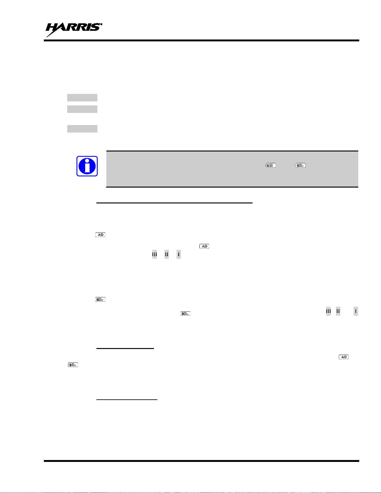
MM-008212-001, Rev. L
SCAN DIS
The radio is not programmed to scan.
FIXED P1
A Priority 1
programmed into the radio. A new Priority 1
group
FIXD LST
A fixed scan list has been pre-programmed into the radio. It is not possible to change the
list without reprogramming the radio.
NOTE
stops at priority level 1. To select a lower priority level, t he group/channel must be deleted from the
scan list and then added back to the sca n list. Each new group/channel added to the scan list start s at
the lowest priority. If the Priority 1 and Priority 2 group/channel are already set and a new
group/channel is assigned as Priority 1 or Priority 2, the previously assigned group will change to
non-priority scanning. One of the following messages may be momentarily displayed.
group/channel has been pre-
/channel cannot be selected.
To quickly view multiple group scan status, press eith er or the key. Then slowly
rotate the group knob. Each group/channel status will appear on the display.
10.18.3 Delete Groups or Channels from a Scan List
P5350 Model Radio
1. With scan operation turned OFF, select the desired group/channel to delete from the selected scan list.
2. Press . The current status of the group/channel i s displayed for a time-out period.
3. While the current status is displayed, press . until the group/channel from the scan list is "blank."
The sequence is "blank," , , ,"blank." Any group/channel that is not in a scan list shows a
"blank" for the time-out period when it is the selected group/channel.
P5370 Model Radio
1. With scan operation turned OFF, select the desired group/channel to delete from the selected scan list.
2. Press . The current status of the group/channel is displayed for a time-out period.
3. While the status is displayed, press
to delete the group/channel from the scan list. , , or
turns OFF. Any group that is not in a trunked system group scan list will show a "blank" for the time
out period when it is the selected channel.
10.18.4 Nuisance Delete
A group/channel can also be deleted from the scan list, if i t is not currently selected , by pressing or
during scan operation while the radio is displaying the unwanted group/channel. The group/channel
is deleted from the scan list in the same manner as if done using the steps above. Deletions done in this
manner will not remain deleted if the radio is powered OFF and then powered ON.
10.18.5 Mixed Zone Scan
The Mixed Zone Scan (MZS) feature gives the u ser the capability to scan based on a custom scan list th at
is assigned at the system level. The Custom Scan (CS) list can contain System and Channel/Group
configurations across Analog Syst ems. MZS gives the user the capabi lity to scan beyond the selected
system group set.
75
Page 76

MM-008212-001, Rev. L
NOTE
NOTE
10.18.5.1 Cust om Scan List Selection
The Custom Scan List is assigned at the System level. Scanning protocols (Custom Scan, System Scan,
and Conventional Priority Scan) are mutually exclusive. Once a custom scan list is assig ned to a system,
when you enable scan, you are scanning the channels/groups defined in the custom scan list. A Custom
Scan List can be assigned to a sy stem through RPM only. The radio supports up to 10 Custom Scan lists,
with up to 50 channels/groups in each.
10.18.5.2 Vi ew Custom Scan Lists
Scan must be off to view a Custom Scan List.
1. From the radio menu, select CUSTSCAN.
2. Select the desired group/channel from the Custom Scan list. Options available for each
channel/group include:
• View the channel’s/group’s scan priori ty.
• Delete the channel/group from the scan list.
• Nuisance delete the channel/group.
3. Press the Option button to back up one display; press the Clear button to return to the home screen.
10.18.5.3 Edit Custom Scan Lists
Scan must be off to edit a Custom Scan List.
1. From the radio menu, select CUSTSCAN.
2. Select EDIT LST.
3. Select the desired system from the list.
4. Select the desired channel group. Scroll through available options:
• Add the channel/group to the scan list.
• Change the channel’s/group’s scan priority.
• Delete the channel/group from the scan list.
• Nuisance delete the channel/group.
5. Press the Option button to back up one display; press the Clear button to return to the home screen.
76
Page 77

MM-008212-001, Rev. L
10.19 SCAN TRUNKED SYSTEMS (EDACS)
The radio can be programmed with the following System Scan feat ures. These features are automati cally
enabled when the radio is powered ON . A key or menu option is also defined to allow the System Scan
features to be toggled during radio operation. The System Scan state will be maintained through system
changes but will default to ON when the radio i s powered ON.
Enable/Disable via Menu Selection
Press and then use or to scroll through the selections until SYS SCAN is display ed. Then
press to toggle the System Scan state. The SYSC ON or SYSC OFF display message is displayed for
two seconds to show the new state.
Enable/Disable via Pre-Programmed Keypad Key
Press the key pre-programmed to toggle System Scan and the SYSC ON or SYSC OFF d isplay message
is displayed for two seconds to show the new st ate.
10.19.1 Wide Area System Scanning
The P5300 series radio can be programmed for Wide Area System Scan operation for roaming across
mobile systems. Upon the loss of the currently selected system's control channel, radios can be
programmed to automatically scan the control channels of other systems. If a new control channel is
found, the radio will switch to the new system and sound an alert tone. The amount of time before the
radio enters Control Channel Scan after losing the control channel is configurable in RPM.
10.19.2 Priority System Scan
The radio can also be programmed for Priority System Scan. The priority system is the desired or
preferred system. While receiving the control channel of the selected system, the radio will periodically
leave the selected system and search for the control channel of the priority system. This is done at a
™
programmable rate defined by the value in th e Priority Scan Time contro l (unless the Pro Scan
algorithm
is enabled, as explained in the following sectio ns). This priority scan timer is reset each time the PTT
button is pressed or when the call is received. If the priority system control channel is found, (or meets the
predefined criteria <ProScan>), the radi o will automatically switch to the priority system.
10.19.2.1 Enabl ing the Wide Area System Scan Function
If the radio cannot find the control channel o f the selected system and begins to wide area system scan,
the radio will only scan for the priority system control channel if the priority system is in the wide area
scan list.
10.19.2.2 W hen Pr oScan i s Enabled
The radio monitors the priority system and will switch to the priority system if the criteria defined by the
controls in the ProScan Options dialog box are met. If ProScan is enabled, the rate at which the radio will
scan for the priority system is defined by the System Sample Time control, located in the ProScan
Options dialog box. See Section 10.19.3 for more information on ProScan.
10.19.3 ProScan
The radio may be programmed for ProScan system scan operation for multi-site applications depending
on the version of radio flash code. ProScan is an improved multi-site system scanning algorithm designed
to replace ProSound
™
scanning. ProScan provid es the radio with the abi lity to select a new s ystem for th e
radio to communicate on, when the selected system drops bel ow a predefined lev el. This is accomplished
77
Page 78

MM-008212-001, Rev. L
by enabling each radio to analyze the signal quality of its current control channel and compares it with the
signal quality of the control ch annel for each site in its adjacent scan l ist. [The signal quality metric used
for the ProScan algorithm is based on a combination of both Received Signal Strength Indicator (RSSI)
and Control Channel Verification (CCV) measurements.] When the selected system degrades to a preprogrammed level, the radio will begin to look for a better control channel. Once a control channel that
exceeds the pre-programmed parameters is found, the radio will change to the new system and emit a tone
(if enabled through programming). If the control channel is completely lost, the radio will enter Wide
Area System scanning and search the programmed adjacent systems until a suitable control channel is
found.
10.20 EMERGENCY OPERATION
The radio's ability to declare an emergency , clear an emergency, remain locke d on an emergency system
and group, and the emergency audio and display freeze can each be enabled or disabled through
programming. When an emergency is declared scanning will stop and restarts only after the emergency
has been cleared.
10.20.1 Receiving an Emergency Call
When receiving an Emergency Cal l on the selected group and system, an alert beep is heard and is
displayed. The message *RXEMER* flashes in the display on line two until the emergency condition is
cleared.
10.20.2 Declaring an Emergency Call
Perform the following steps to send an emergency call to a selected system and group (or on an optionally
pre-programmed group).
1. Press and hold the red EMERGENCY button that is on top of the radio in front of the antenna for
approximately one second (this time is programmable and therefore could be longer or shorter; check
with the system administrator). The ra dio will transmit an emergency call request with th e radio ID
until an emergency channel assignment is received.
2. When the working channel assignment i s received, th e radio sounds a single beep indicating the radio
has auto keyed (see Table 10-5) and is ready for vo ice transmission. *TXEMER* flashes on line two
in the display until the emergency is cleared.
3. Press PTT and speak into the microphone in a normal voice. and momentarily turn ON.
4. Release PTT when the transmission is co mplete.
To clear the emergency first press and h old the button. While continuing to hold the button, press
the EMERGENCY button. (This will work if the radio is programmed to clear emergencies.)
78
Page 79

MM-008212-001, Rev. L
10.21 MIXED SYSTEM ZONES
A Zone is a grouping of analog conventional channels, P25 conventional channels, and/or talkgroups.
Mixed System Zones are defined in RPM and can be comprised of any combination of channels/groups
from multiple systems. If a Mixed System Zone is not configured in RPM, it will not appear on the radio.
Up to 50 Mixed System Zones can be defined.
To select a Mixed System Zone:
1. Press .
2. Press or to select ZONE and press .
3. Press or to select the desired Mixed System Zone and press .
Alternately, the System/Group/Channel knob or a button on the radio can be programmed to scroll
through available Mixed System Zones.
When scan is enabled on a system in a Mixed System Zon e, the radio cont inues to display the zone n ame
or system name per the current radio mode (system/zone). When toggling scan ON/OFF, there is no
change one line 1 of the radio display. If it is showing system name, it continues to show sy stem name; if
it is showing zone name, it continues to show the zone name during scanning.
10.22 CALLER ID
This feature allows you to view the caller I D or alias for up to the last 10 recei ved calls. Received calls
include Group, Announcement, Phone, Patch, SimulSelect, Agency, Fleet, and MDC.
1. Press and press or to select CALL ID. Press . Alternately, a button can be
programmed to access the CALL ID list.
2. Press or to scroll through available entries. “NO ENTRY” is displayed if there are no
entries.
The most recent call is displayed at the top of the list. The Caller ID list is cleared when power is cycled
on the radio.
10.23 STEALTH MODE
Press the button programmed for Stealth Mode operation to toggle Stealth Mode on or off. During Stealth
Mode, all buttons are disabled except PTT, the button programmed for Stealth operation, Emergency, and
Nuisance delete. The radio will receive and transmit when Stealth Mode is enabled.
The radio can be configured to disable any or all of the following during Stealth Mode:
• LCD display
• LED
• Backlight
• Side/alert tones
Stealth Mode can be configured to persist t hrough a power cycle.
79
Page 80

MM-008212-001, Rev. L
NOTE
10.24 INDIVIDUAL CALLS (EDACS)
10.24.1 Receiving and Responding to an Individual Call
When the radio receives an individual call (a call directed only to the user's radio), it un-mutes on the
assigned working channel and displays . The first line on the display shows the logical ID number of
the unit sending the message, or the associated name if the ID number is found in the individual call list.
The radio can be programmed to ring when an individual call is received. If enabled, the ring begins five
seconds after the caller un-keys and will continue until the PTT button, the button or the individual
call mode is entered.
The volume of the ring is adjustable through the volume control levels.
If a response is made by pressing the PTT to the call prior to the programmed call-back time-out, the call
will automatically be directed to th e originating unit. If a response is not made before the cal l-back timeout, the radio will return to normal receive display, and *WHC* will appear on the first line of the LCD.
To respond after the call-back time-out, press the key. The radio's display will show the callers ID on
the first line and WHCI=1 on the second line. Pressing the PTT button at this point will initiate an
individual call back to the original caller.
The radio stores the IDs of the last 10 callers in the Calls Receiv ed List as shown. Individual calls are
stored in the top half of the list (1-10) and Group calls are stored in the bottom half of the list (1-10). The
most recent call is stored in position 1, the second most recent call is stored in position 2, etc.
Figure 10-11: Calls Received Lists
To access the Calls Received List, press twice. Use or
to scroll through the list. Pressing
will display the time elapsed since the call was received. After pressing , the display will appear
similar to Figure 10-12.
80
Page 81
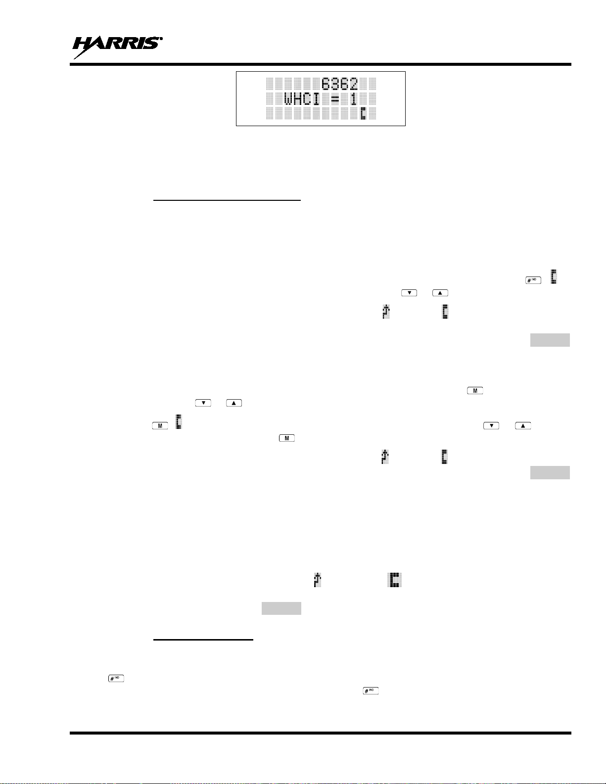
MM-008212-001, Rev. L
Figure 10-12: WHC Individual Call Display
Pressing the PTT will initiate an individual call to the displayed logical ID. Powering the radio OFF and
ON will clear this list.
10.24.2 Sending an Individual Call
10.24.2.1 Pre-Stored Individual Calls
The following procedures describe how to initiate and complete a Pre-Stored Individual Call.
P5370 Model Radio
1. To select a pre-stored individual phone number, enter the individual call mode using . is
displayed. Then scroll through the list of stored numbers using or
2. Press the PTT button; when the radio is clear to transmit, turns ON, turns OFF and the channel
access tone sounds. Line one shows the called individual's name if found in the list of stored
individuals or LID followed by the logical ID number of the unit being called. The message *INDV*
displays on line two.
.
P5350 Model Radio
1. To select a pre-stored individual number, enter the menu mode by pressing . Scroll through the
mode list using or
2. Press . is displayed. Scroll through the list of stored phone numbers using or
.
until the
desired number is displayed. Press .
3. Press the PTT button; when the radio is clear to transmit turns ON, turns OFF and th e channel
access tone sounds. Line one shows the called individual's name or LID. The message *INDV*
displays on line two.
10.24.2.2 Di r ect Dial Individual Calls (P5370 Model Only)
1. The following procedure describes how to initiate and complete a Direct Dial Individual Call.
2. The individual call ID is not stored in the pre-stored list of call IDs but the individual unit ID is
known, it can be entered directly from the keypad.
3. Press and hold the PTT button to transmit. will turn ON, will turn OFF, and the chann el acces s
tone will sound. Line one shows the called individual's ID followed by the logical ID number of the
unit being called. The message *INDV* displays on line two. Proceed talking into the microphone.
10.24.3 Call Storage Lists
There are two lists available for call storage i n the P5300 series radios; the calls received list (1 - 10) and
the personality list (1 - 99 as defined by the user). When the individual cal l mode is entered by pressing
, the calls received list is available. The user can togg le to the personality li st by selecting any index
other than 0 or toggle between the two lists by pressing . If wrap is enabled, the calls received list
wraps on itself and not into the other list.
81
Page 82

MM-008212-001, Rev. L
Figure 10-13: Calls Received and Personality Lists
The saved call list shows all ten storage locat i ons. If no calls have been received, the saved call list will be
empty and the pre-stored list will be available upon entering the individual call mode.
When in the saved call list, pressing toggles the time stamp ON and OFF. The time stamp indicates
how long ago the call was received. When in the pre-stored list pressing toggles the Logical
IDentification (LID) ON and OFF.
10.25 TELEPHONE INTERCONNECT CALLS (EDACS)
10.25.1 Receiving a Telephone Interconnect Call
When the radio receives a telephone intercon nect call (a call di rected on ly to the user's radio ), it un-mutes
on the assigned working channel and displays . The first line displays *PHONE*. The second line
displays *INDV*. Proceed with the call. Press the PTT to talk, release the PTT to listen.
10.25.2 Sending a Telephone Interconnect Call
10.25.2.1 Pre-Stored Number
Use the following procedures to initiate and complete a Telephone Interconnect call.
1. P5370 Model: To select a previously stored phone number, press . Use or
through the list of stored numbers.
P5350 Model: To select a previously stored phone number, press . Use or
menu option PHN CALL. Press again, and then use or to scroll through the list of prestored numbers.
2. Press and release the PTT button. When the radio is clear to transmit, turns ON, turns OFF and
the channel access tone sounds. Line one shows the accompanying name selected from the list of
stored numbers. The message *PHONE* appears on line two of the display. The radio then
automatically transmits the programmed number stored in the special call queue.
to scroll
to select the
82
3. A telephone ring will be heard fr om the speaker. When someone answers th e phone, press the PTT
button and speak into the microphone. Release the PTT button to listen to the callee. Unsuccessful
interconnect signaling returns the radio to the normal receive mode and the number remains displayed
until the special call is cleared or the time-out expires or another group or system is selected.
Terminate a call by pressing .
Page 83

MM-008212-001, Rev. L
to be pressed in order to communicate to the individual called and released for the
NOTE
NOTE
In half-duplex mode, only one person may talk at a time. The radio PTT button needs
individual called to be heard.
10.25.2.2 Direct Dialing of Phone Calls (P5370 Model Only)
1. If the phone number is not stored in the pre-stored list of phone numbers, but the phone number is
known, it can be entered directly from the keypad. Start by pressing , then enter the required
number from the keypad. Press and release the PTT button.
The last number directly entered can be recalled by fir st pressing , then pressing
the PTT button.
2. A telephone ring can be heard from the speaker. When someone answers the phone, press and hold
the PTT button and speak into the microphone. Release the PTT button to listen to the individual
called. Unsuccessful interconnect signaling returns the radio to the normal receive mode and the
number remains displayed until the special call is cl eared or the time-out expires or another group or
system is selected.
3. To terminate the call, momentarily press .
10.25.3 Dual-Tone Multi-Frequency: Overdial/Conventional Mode
Once the radio has established a connection to th e public telephone system, it may be necessary to “overdial” more digits to access banking services, answering machines, credit card calls, or other types of
systems that require Dual-Tone Multi-Frequency (DTMF) access digits.
Overdial operation can also be used to initiate a telephone interco nnect call via DTMF signaling if a dial
tone has already been accessed on the sy stem. This method makes a telephone interconnect call while
operating in the conventional mode but will also function in trunked mode if a dial tone is directly
accessible.
Telephone numbers and other number sequences for overdialing can be stored in the phone list when
programming the radio. These numbers are a ccessed by pressing , then following the selection mode
rules. Perform the following procedures to access and dial these stored numbers.
P5350 Model Radio
1. Follow the procedure in Section 10.25.2 to establish a connection to the telephone sy stem or consult
the system administrator for the procedure to access a dial tone on the trunked or conventional
system.
2. Enter selection mode first to enable entry of Over dial numbers by pressing .
3. Follow the selection mode rules to call up a stored number from the phone list: Use or
scroll through the list of stored numbers. is displayed. Press the PTT to send the overdial sequence
once. If the number needs to be transmitted again it must be selected or entered again (this prevents
unwanted numbers from being sent the next time the PTT button is pressed during the call).
Overdial select/entry mode remains active until the call is dropped, cleared, or is pressed. The
overdial select/entry mode can be re-entered if the call is still active by pressing .
to
83
Page 84

MM-008212-001, Rev. L
METHOD 1:
2.
Press the
If the number needs to be transmitted again
it must be selected or entered again (t his prev ents unwan ted nu mbers from bein g sent
O
is
pressed. The overdial select/entry mode can be re-entered if the call is still active by
pressing .
METHOD 2:
(
1.
2.
while entering the overdial number sequence from the
keypad. This method sends DTMF tones during individual, telephone interconnect,
Press the PTT to send the overdial
transmitted again it must be selected or
entered again (this prevents unwanted numbers from being sent the next time the PTT
Anytime the PTT button is pressed and held, the keypad is enabled for
O
is
pressed. The overdial select/entry mode can be re-entered if the call is still active by
pressing .
NOTE
P5370 Model Radio
1. Follow the procedure in Section 10.25.2 to establish a connection to the telephone sy stem or consult
the system administrator for the procedure to access a dial tone on the trunked or conventional
system.
2. Overdial numbers are transmitted using one of the following methods:
1. Enter the overdial selection mode by pressing .
Use or to scroll through the list of stored numbers. is disp lay ed .
PTT to send the overdial sequence once.
the next time the PTT button is pressed during the call).
verdial select/entry mode remains active until the call is dropped, cleared, or
P5370 model radios only)
Enter the overdial selection mode by pressing the button.
Press and hold the PTT button
trunked group, or conventional channel calls.
sequence once. If the number needs to be
button is pressed during the call).
DTMF entry.
verdial select/entry mode remains active until the call is dropped, cleared, or
This overdial select/entry mode remains active until dropped, cleared, or is pressed. The overdial
select/entry mode can be re-entered if the call is still active by pressing .
10.26 PROGRAMMABLE ENTRIES (EDACS)
Individual Call ID numbers, telephone numbers, and other number sequences for overdialing are stored in
the special calls lists when programming the radio. The first ten entry locations of these lists can be
changed by the radio operator. The keypad is used when adding, changing, and storing numbers in these
entry locations.
Use the following procedure to store a number in one of the first ten entries of a special call list:
1. Press the or button to enter the individual call list or the phone call list. is displayed.
2. Scroll through the list using or until one of the first ten entr ies is reached. NO ENTRY is
displayed if the location is empty.
3. Enter the desired number. If necessary , a pause can be entered by pressing and hol ding 0-9, , or
84
until an underscore appears in the display (telephone interconnect only). The individual call list
Page 85

MM-008212-001, Rev. L
METHOD 1:
programmed status
programmed status selections are available
2. If STATUS is selected, you need to enter the number of the status condition you
s has been programmed for the selected number key, the
NO ENTRY
-
After the time
out
period), the status
transmitted to the site or stored in the radio memory
where it can be polled by the site at a future time.
METHOD 2:
2.
If no
status has been programmed for the selected number key, the radio will display
NO ENTRY
top
display for a
After the time
out period),
the status is selected and will be transmitted to the site or stored in the radio memory
where it can be polled by the site at a future time.
entries will accept up to 5 digits. The phone call list entries accept a combination of up to 31 digits
and pauses.
4. Press and hold until the display changes indicating that the number has been stored.
Repeat steps 1-4 to store additional numbers, to change numbers alread y stored, or to change the storage
location of a number.
10.27 STATUS/MESSAGE OPERATION (EDACS)
The Status and Message operations allow for the transmission of a pre-programmed status or a preprogrammed message to an EDACS site. Each Status and Message is assigned an ID then cross-
referenced with the representative status con di tion ( “Off Duty , ” for example) o r a messag e (“C all h o me”).
In addition, Status conditions can also be associated with a programmable Menu entry (required for
second method of transmitting a Status condition (see Section 10.27.1).
10.27.1 Status Operation
P5370 Model Radio
One of two methods can be used to transmit a status condition.
1. Press , then use the or buttons to scroll to the precondition. STATUS and 0 through 9 prefrom the menu.
intend to transmit. If no statu
radio will display
programmed time.
-out expires or the key has been pressed ( overrides the timeis selected and is
1. Press .
Press the corresponding pre-programmed 0 through 9 status condition key.
. A valid selection will permit the status condition to appear in the
line of the display and the status ID to appear in the second line of the
pre-programmed time.
-out expires or has been pressed ( overrides the time-
View the currently selected status after it has been transmitted by pressing and to ramp to STS.
Press again and press prior to the time-out peri od. If the status was not sent successfully to the
site, the text associated with the status condition will flash in the display.
The status selection can be changed by pressing a different status key 0 through 9, or the status operation
can be cancelled by pressing . Both operations must be carried out prior to the time-out period.
. A valid selection will display the status for a pre
85
Page 86

MM-008212-001, Rev. L
10.27.2 Message Operation
The following method can be used to transmit a Messag e using the Message Operation.
1. Press the key.
2. Press the corresponding pre-programmed 0 through 9 pre-programmed “message” key. If no message
has been programmed for the selected number key, the radio will display NO ENTRY. A valid
selection will permit the message to appear in the top line of the display and the message ID to appear
in the second line of the display for a pre-programmed time.
The message selection can be changed by pressing a different message key 0 through 9, or the message
operation can be cancelled by pressing . Both operations must be carried out prior to the preprogrammed time-out period.
10.28 DYNAMIC REGROUP OPERATION (EDACS)
Dynamic Regroup Operation permits multiple talk groups (up to eight) to be added to a radio via the
system manager. The radio must be pre-programmed to respond to regrouping. Dynamic regrouping will
not be activated in a radio until the system manager sends an activation message. Each r adio that rec eives
and acknowledges the regrouping instructions is successfully regrouped.
Pressing and holding the button for 2.5 seconds toggles the user into and out of the dynamic regroup
groupset. A double beep will sound for entry or exit. The display will indicate REGRP_0x where "x" is a
digit of 1 to 8 indicating the group (when dynamic regroup has been enabled by the user). If the radio is in
dynamic regroup and the user selects a group that has not been regrouped, the display will show NO
ENTRY. The radio will be prevented from transmitting and receiving calls in this condition except for
scanned groups.
After the time-out expires or the key has been pressed (the key will override the time-out
period), the status is selected and will be tran s mitted to the site or stored in the radio memory where i t c an
be polled by the site at a future time.
10.28.1 Emergency Operation
If the pre-programmed groupset on the currently selected system contains an EMER/HOME group and
the radio is in dynamic regroup, the radio will declare the emergency on the currently selected dynamic
group.
10.29 MACRO KEY OPERATION
Macro key operation permits the user to accomplish a series of keystrokes with a single "macro"
keystroke. Each Macro Key is capable of executing up to twenty (20) keystrokes, to any push button input
(i.e., keypad keys, OPTION buttons, etc.). Each macro key can be pre-programmed to activate when
pressed or when released.
A macro key may also be pre-programmed t o ch ang e the k ey st roke sequen ce th e n ext ti me the macro k ey
is activated. For detailed operation and assignment of macro keys, contact your communications
supervisor or administrator.
10.30 PORTABLE DATA
The P5300 series portable radios permit both voice and data calls to be transmitted and received. The
radio can handle only one type of call at a time; howe ver, either data or v oice is selected transparen tly by
the operator through normal usage of the radio.
86
Page 87

MM-008212-001, Rev. L
DATA T/R
Appears on top line of display when the radio is transmitting/receiving a data call.
DATA OFF
Appears on top line of display when the radio is in the data disabled state.
DATA ON
Appears for two seconds on top line of display when the radio is toggled to the data
enabled state.
The radios can be connected to a Mobile Data Terminal (MDT) or to a host computer. Any RS-232
compatible device that supports the Radio Dat a Interface (RDI ) protoco l (Version 1.9 1 or greater) may b e
connected to the radio. Support for MDTs or host computers is a programmable option per radio.
Additionally, radios may also be programmed for data only operation (no voice calls transmitted or
received).
10.30.1 Displays
The following will be displayed during data operation:
10.30.2 DATA OFF Operation
The radio can be placed in the data disab led state b y any of the fol lowing metho ds. When th e data state i s
disabled, DATA OFF appears on the top line of the display.
• Declaring an emergency (not to be u sed unless an act ual emergency co ndition exists). Alert t one will
sound.
• Pressing (if pre-programmed as “no data” key). Alert tone will sound.
• Pressing the pre-programmed “no data” (ND) key. Refer to previous bullet.
10.30.3 DATA ON Operation
The data state is enabled by one of the following (dep ending on how it was disabled). DATA ON will
appear on the top line in the display for two seconds then the display will return to normal.
• Pressing the pre-programmed “no data” (ND) key toggles data state ON or OFF.
• Clearing an emergency. This is valid only if the emergency caused “DATA OFF” operation.
10.30.4 Exiting Data Calls
Under normal conditions, the radio enters the scan lockout mode and returns to the control channel after
completion of a data call (transmit or receive). If, during a data call, one of the following operations
occurs, the data call is immediately terminated and the radio performs the desired function:
• If the PTT is activated.
• If an Emergency is declared by pressing the pre-programmed emergency button.
• If a group or system is changed.
10.30.5 Scan Lockout Mode
Following the transmission or reception of a data call, if scan is enabled, scanni ng will stop temporarily.
There are two independent pre-programmed times associated with this mode; one after a recei ved data
call and one after a transmitted data call. During this time the scan indicator will flash to indicate that scan
is enabled but temporarily suspended. This condition typically returns to normal scan operation when the
pre-programmed time expires; however, the following operations and conditions will terminate the scan
lockout mode before the timeout has expired.
87
Page 88

MM-008212-001, Rev. L
• Press the button.
• Press the PTT.
• Change a group or system.
• Enter Telephone Interconnect mode.
• Enter Individual call mode.
• Receive a new emergency assignment.
• Declare or clear an emergency.
• Receive an individual or phone call.
• Receive an Agency, Fleet, or System All Call.
• Press or to toggle Scan ON or OFF.
10.30.6 Data Lockout Mode
During the voice call scan hang time (pre-pr ogrammed) the radio will not receive data calls.
10.31 TYPE 99 OPERATION (CONVENTIONAL ONLY)
Type 99 is Harris Corporation’s proprietary method for in-band, two-tone sequential signaling. Type 99
is a conventional signaling protocol that controls the muting and unmuting of a radio. Type 99 encoded
base stations, mobiles, or portables can selectively call individual units or groups of units in a
conventional system. Type 99 is used in paging operations providing a dispatcher with the ability to
selectively call a radio or a group of radios. If Ty pe 99 is enabled in the radio personality , the radio can
decode Individual, Group, and Supergroup Type 99 calls.
In a selective signaling environment, the P5300 portable radios operate in one of two states, Monitor
mode or Selective Call mode.
• In Monitor mode, Type 99 “OFF,” the decoder is disabled and all calls are heard by the user.
• In Selective Call mode, Type 99 “ON,” the d ecoder is enabled and only calls intended for the user
will be heard.
10.31.1 Type 99 with or without Channel Guard
Selective signaling operates with or without Channel Guard. If Channel Guard is enabled, the radio can
be programmed with an "And" or an "Or" option, determined by programming with T99 Mute Control.
• If the "And" option is programmed, T99 calls require the correct selective signaling (T99 tone
sequence) AND the correct Channel Guard tones ar e heard by the user.
• If the "Or" option is programmed, calls with the correct Channel Guard tones OR calls with the
correct T99 tone sequence and Channel Guard tones are heard by the user.
A radio operating in Selective Call mode th at rec eiv es a selective call switches to the Monito r mode (after
decoding a T99 call) and the TX/RX LED flashes green. The TX/RX LED indicates whether the
channel has a carrier signal.
88
Page 89
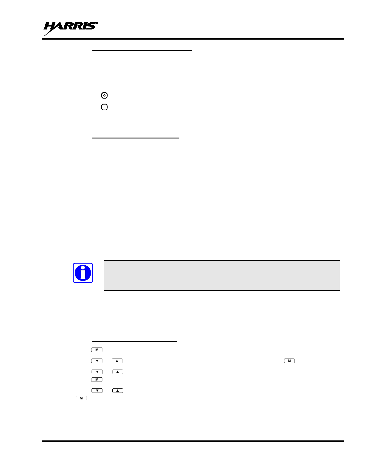
MM-008212-001, Rev. L
NOTE
10.31.2 Resetting Type 99 after a Call
After decoding a Type 99 call, the radio operates in Monitor mode and all traffic on the channel is
audible. If the channel has Channel Guard, only the traffic with the radio's Channel Guard tone will be
heard.
To reset Type 99 operation, use one of the following methods:
• Press the button.
• Press the button if enabled through programming to toggle Type 99 ON/OFF.
• Allow the "Auto-Reset" timer, if enabled through programming, to reset the Type 99 decoder.
10.31.3 Type 99 Disable after PTT
The radio may be programmed with the Type 99 Disable after PTT feature, which aut omatically disables
the Type 99 decoder after a transmission.
Use one of the methods outlined in the “Resetting Type 99 after a Call” section to reset Type 99
operation.
10.32 AUDIO PLAYBACK
Every call received by the radio is recorded in internal memory, overwr iting the last recorded call. When
the PLAYBACK key is pressed, the last recording is replayed and any future recordings are stopped.
Pressing PLAYBACK again repeat s the same recorded call. Pressing and ho lding the PLAYBACK key
until the tone sounds erases the recording and starts the recording of incoming calls again. If a call is
received while the recorded call i s playing, the recorded call continues to p lay, rather than the received
audio. However, if a call is received and th e recorded call is played back in close succession received
audio could mute call playback. This feature requires RPM R8A and later, and ECP R15A and later .
The PLAYBACK function must be programmed to a button on the radio via RPM.
10.33 RADIO TEXTLINK OPERATION
Radio TextLink provides a simple means of exchanging pre-defined, or “canned,” text messages. This
section describes how to send messages if the Radio TextLink feature is enabled.
10.33.1 Send TextLink Messages
1. Press to access the menu.
2. Press or to scroll through menu until SND MAIL is displayed. Press to select.
3. Press or to scroll through the pre-defined messages th at scroll across th e top of the d isplay.
Press to select to select the desired message.
4. Press or to scroll through the list of available destination IDs and select the desired ID with
.
89
Page 90

MM-008212-001, Rev. L
10.33.2 Receive TextLink Messages
Received Messages are listed in th e order in which they are received (newest at the top). All messages
include the user LID along with the date and time stored/displayed. The mailbox can hold 16 messages at
a time. If a new Message arrives after the limit is reached, the new message overwrites the oldest
message.
1. Press to access the menu.
2. Press or to scroll through menu until RD MAIL is displayed. Press to select.
3. Scroll through the list of received messages using the or key.
4. Selecting a received message with the key will bring up a reply to sender option.
10.33.3 Delete TextLink Messages
Select DEL MAIL with the key to delete AL L messages in the inbox.
10.33.4 View the Current Time
Select TIME with the key to retrieve the current date and time.
10.34 VIEW GPS INFORMATION
If GPS is enabled in RPM and the GPS Speaker microphone or GPS dongle is connected to the P5300,
view your position and satellite information via the GPS Menu. GPS requires an unobstructed view of
the sky and the signal is greatly diminished inside buildings, tunnels, heavily forested areas, etc. GPS may
not work at all under some conditions, especially in metal enclosures or buildings. flashes o n the radio
display when the GPS signal is being acquired; stops flashing after signal is acquired.
1. Press to access the menu.
2. Press or to scroll through menu until GPS is displayed and press to select.
3. Press or to scroll through available information screens.
10.35 CONTROL AND STATUS SERVICES
The P5300 supports Control and Status services. These services allow the computer application to
monitor and control a radio. The Control and Status Services can be used from a locally-connected
Mobile Data Terminal (MDT) or a network MDT. In some cases, the radio can support both MDTs
simultaneously. However, priority is given to the local MDT.
The Radio Status Service allows an MDT or Fixed End System (FES) to receive real-time status upd ates
from a radio. An MDT sends Host Att ach/Detach messages to the radio as UDP datagra ms destined for
the UDP Service Address and Serv ice UDP Port of the radio. All respo nses and asyn chronous reports are
returned to the address and port of the requesting host. Refer to the ECP Control and Status Services
Feature Manual, 14221-7200-6040, for more information on this feature.
90
Page 91

MM-008212-001, Rev. L
11 CUSTOMER SERVICE
11.1 CUSTOMER CARE
If any part of the system equipment is damaged on arrival, contact the shipper to conduct an inspection
and prepare a damage report. Save the shipping container and all packing materials until the inspection
and the damage report are completed. In addition, contact the Customer Care center to make
arrangements for replacement equipment. Do not return any part of the shipment until you receive
detailed instructions from a Harris representative.
Contact the Customer Care center at https://www.harris.com/solution/pspc-customer-service or:
North America:
Phone Number: 1-800-368-3277
Fax Number: 1-321-409-4393
E-mail: PSPC_CustomerFocus@harris.com
International:
Phone Number: 1-434-455-6403
Fax Number: 1-321-409-4394
E-mail: PSPC_InternationalCustomerFocus@harris.com
11.2 TECHNICAL ASSISTANCE
The Technical Assistance Center's (TAC) resources are available to help with overall system operation,
maintenance, upgrades and product support. TAC is the point of contact when answers are needed to
technical questions.
Product specialists, with detailed knowledge of product operation, maintenance and repair provide
technical support via a toll-free (in North America) telephone number. Su pport is also available through
mail, fax and e-mail.
For more information about technical assistance services, contact your sales representative, or call the
Technical Assistance Center at:
North America: 1-800-528-7711
International: 1-434-385-2400
Fax: 1-434-455-6712
E-mail: PSPC_tac@harris.com
91
Page 92

MM-008212-001, Rev. L
transmitting if an operational
Let the radio cool before attempting to transmit.
Radio may be experiencing very low
Have the battery checked by an authorized
Return to coverage area if possible. If
overheated, let radio cool before retrying
12 BASIC TROUBLESHOOTING
Use Table 12-1 as a troubleshooting guide if the radio is not functioning properly. If additional assistance
is required, contact a qualified service technician or call Harris at 1-800-528-7711.
Table 12-1: Troubleshooting
SYMPTOM POSSIBLE CAUSE POSSIBLE SOLUTION
Radio will not turn on. Low battery charge. Change the battery pack to a fully charged pack .
No Audio. Speaker volume is muted. Increase the volume level.
Poor Audio
Radio will not register or
does not receive
provisioning data.
Screen displays:
NOAUTHV
Screen displays:
NOAUTHM
Screen displays:
UNAUTH3
Screen displays:
NOSUPRT
Screen displays:
BAD PWD
Screen displays:
OVR TEMP
Radio powers off for no
apparent reason.
Radio will not transmit.
• User is in a poor coverage area or n ot
on the network.
• Data cable is connected.
Bad logon credentials. Verify logon and password.
Radio authentication of the VNIC fai led. Contact system administrator.
VNIC authentication of the radio failed. Contac t system administrator.
The radio network ID has not been a dded
to network.
The voice authentication security policy is
set to only allow authenticated users.
An invalid password has been entered. Verify the password and re-enter.
The radio may be too hot. The radio will
cease
temperature threshold has been exceeded.
voltage.
Radio may be out of coverage area or may
be overheated.
• Move to a better coverage area.
• If the data cable is connected, enter “atspkr 1”
to enable internal speaker.
Contact system administrator.
Contact system administrator.
Report this failure to an authorized technician.
technician.
transmission. Report this failur e to an authorized
technician.
92
Page 93

MM-008212-001, Rev. L
13 WARRANTY
Please register this product within 10 days of purchase. Registration validates the warranty co verage, and
enables Harris to contact you in case of any saf ety notifications issued for this product.
Registration can be made on-line at the Customer Care center webpage:
https://www.harris.com/solution/pspc-customer-service
While on the webpage, please review the app l icable battery and/or product warranty literature.
93
Page 94

About Harris Corporation
critical solutions that connect,
inform and protect the world. The company’s
information and
insight to customers operating in demanding
between. Harris has approximately $8 billion in
annual revenue and supports customers in 125
focused business
ments: Communication Systems, Space and
Harris Corporation is a leading technology innovator
that creates mission-
advanced technology provides
environments from ocean to orbit and everywhere in
countries through four customerseg
Intelligence Systems, Electronic Systems, and Critical
Networks.
FLORIDA NEW YORK VIRGINIA BRAZIL UNITED KINGDOM UAE SINGAPORE
 Loading...