

Page 1

OTM-20
Optical Test Meter
Installation and Operation Handbook
ONE-YEAR LIMITED WARRANTY
Videotek, Inc. warrants that this product is free from defects in materials and workmanship for a period of one year from the date
of purchase. During this warranty period, Videotek will, at its option, repair or replace defective products at no charge for the
parts or labor. Batteries are not covered in the warranty.
For warranty service or repair, this product must be returned to a service facility designated by Videotek in the original packing or
its equivalent. The purchaser shall insure the product and prepay shipping charges to Videotek, and Videotek shall insure the
product and pay shipping charges to return the product to the purchaser.
The foregoing warranty shall not apply to defects or damage resulting from improper or inadequate maintenance by the
purchaser, connecting the product to incompatible equipment, misuses, operation outside any environmental specification for the
product, improper site preparation or maintenance, or attempts by personnel other than authorized Videotek representatives to
repair or service the product.
No other warranty is expressed or implied. Videotek specifically disclaims the implied warranties of merchantability and fitness for
a particular purpose. The remedies provided by the foregoing warranty are the purchaser's sole and exclusive remedies.
Videotek shall not be liable for any direct, indirect, special, incidental or consequential damages, whether based on contract, tort,
or otherwise.
Printed February 2007
Item #261345 Rev. A
Copyright © 2006 - 2007 by Videotek, Inc.
All rights reserved.
Contents of this publication may not be reproduced in any form without permission of Videotek, Inc.
This instrument, in whole or in part, may be protected by one or more US or foreign patents or patent applications.
Specifications subject to change without notice.
___________________________________________________________________________________________________________
Videotek and the Videotek logo are registered trademarks of Videotek, Inc.
Page 2

VIDEOTEK SOFTWARE LICENSE AND WARRANTY
The software which accompanies this license (the "Software") is the property of Videotek or its licensors and is
protected by copyright law. While Videotek continues to own the Software, you will have certain rights to use the
Software after your acceptance of this license. Except as may be modified by a license addendum which accompanies
this license, your rights and obligations with respect to the use of this Software are as follows:
• You may not:
i. Sublicense, rent, or lease any portion of the Software; or
ii. Reverse engineer, decompile, disassemble, modify, translate, make any attempt to discover the source code
• Limited Warranty:
Videotek warrants that the media on which the Software is distributed will be free from defects for a period of sixty (60)
days from the date of delivery of the Software to you. Your sole remedy in the event of a breach of this warranty will be
that Videotek will replace any defective media returned to Videotek within the warranty period. Videotek does not
warrant that the Software will meet your requirements or that operation of the Software will be uninterrupted or that the
Software will be error-free.
THE ABOVE WARRANTY IS EXCLUSIVE AND IN LIEU OF ALL OTHER WARRANTIES, WHETHER EXPRESS OR
IMPLIED, INCLUDING THE IMPLIED WARRANTIES OF MERCHANTABILITY, FITNESS FOR A PARTICULAR
PURPOSE AND NONINFRINGEMENT. THIS WARRANTY GIVES YOU SPECIFIC LEGAL RIGHTS. YOU MAY HAVE
OTHER RIGHTS, WHICH VARY FROM STATE TO STATE.
• Disclaimer of Damages:
REGARDLESS OF WHETHER ANY REMEDY SET FORTH HEREIN FAILS OF ITS ESSENTIAL PURPOSE, IN NO
EVENT WILL VIDEOTEK BE LIABLE TO YOU FOR ANY SPECIAL, CONSEQUENTIAL, INDIRECT OR SIMILAR
DAMAGES, INCLUDING ANY LOST PROFITS OR LOST DATA ARISING OUT OF THE USE OR INABILITY TO USE
THE SOFTWARE EVEN IF VIDEOTEK HAS BEEN ADVISED OF THE POSSIBILITY OF SUCH DAMAGES.
SOME STATES DO NOT ALLOW THE LIMITATION OR EXCLUSION OF LIABILITY FOR INCIDENTAL OR
CONSEQUENTIAL DAMAGES SO THE ABOVE LIMITATIONS OR EXCLUSION MAY NOT APPLY TO YOU.
IN NO CASE SHALL VIDEOTEK LIABILITY EXCEED THE PURCHASE PRICE FOR THE SOFTWARE. This
disclaimer and limitations set forth above will apply regardless of whether you accept the Software.
• U.S. Government Restricted Rights:
RESTRICTED RIGHTS LEGEND. Use, duplication, or disclosure by the Government is subject to restrictions as set
forth in subparagraph © (1) (ii) of the Rights in Technical Data and Computer Software clause at DFARS 252 227-7013
or subparagraphs © (1) and (2) of the Commercial Computer Software-Restricted Rights clause at 48 CFR 52.227-19,
as applicable, Videotek, Inc., 243 Shoemaker Road, Pottstown, PA 19464.
• General:
This agreement will be governed by the laws of the Commonwealth of Pennsylvania. This Agreement may only be
modified by a license addendum which accompanies this license or by a written document which has been signed by
both you and Videotek. Should you have any questions concerning this Agreement, or if you desire to contact Videotek
for any reason, please write:
Videotek, Inc.
243 Shoemaker Road
Pottstown, PA 19464-6433
of the Software, or create derivative works from the Software
OTM-20 Installation and Operation Handbook
Page 3
OPERATOR'S SAFETY SUMMARY
CAUTION — these instructions are for use by qualified personnel only. To reduce
the risk of electric shock, do not perform this installation or any servicing unless you
are qualified to do so. Refer all servicing to qualified service personnel.
To ensure safety:
• The unit should not be exposed to dripping or splashing, and no objects filled with liquids, such as
vases, shall be placed on the unit.
• When the unit is to be permanently cabled, connect the protective ground conductor before making
any other connections.
• Operate built-in units only when they are properly fitted into the system.
• For permanently cabled units without built-in fuses, automatic switches, or similar protective facilities,
the AC supply line must be fitted with fuses rated to the units.
• Before switching on the unit, ensure that the operating voltage set at the unit matches the line
voltage, if appropriate. If a different operating voltage is to be set, use a fuse with the appropriate
rating. Refer to the Installation Instructions.
• Units of Protection Class I with an AC supply cable and plug that can be disconnected must be
operated only from a power socket with protective ground contact:
− Do not use an extension cable—it can render the protective ground connection ineffective.
− Do not intentionally interrupt the protective ground conductor.
− Do not break the protective ground conductor inside or outside the unit or loosen the protective
ground connection; such actions can cause the unit to become electrically hazardous.
• Before opening the unit, isolate it from the AC supply. Then ensure that:
− Adjustments, part replacements, maintenance, and repairs are carried out by qualified personnel
only.
− Safety regulations and rules are observed to prevent accidents.
− Only original parts are used to replace parts relevant to safety (for example, the power on/off
switches, power transformers, and fuses).
• Replaceable fuses can be hazardous when live. Before replacing a fuse, disconnect the AC power
source.
• Use caution when cleaning the equipment; isopropyl alcohol or similar solvents can damage or
remove the labels.
• Observe any additional safety instructions specified in this manual.
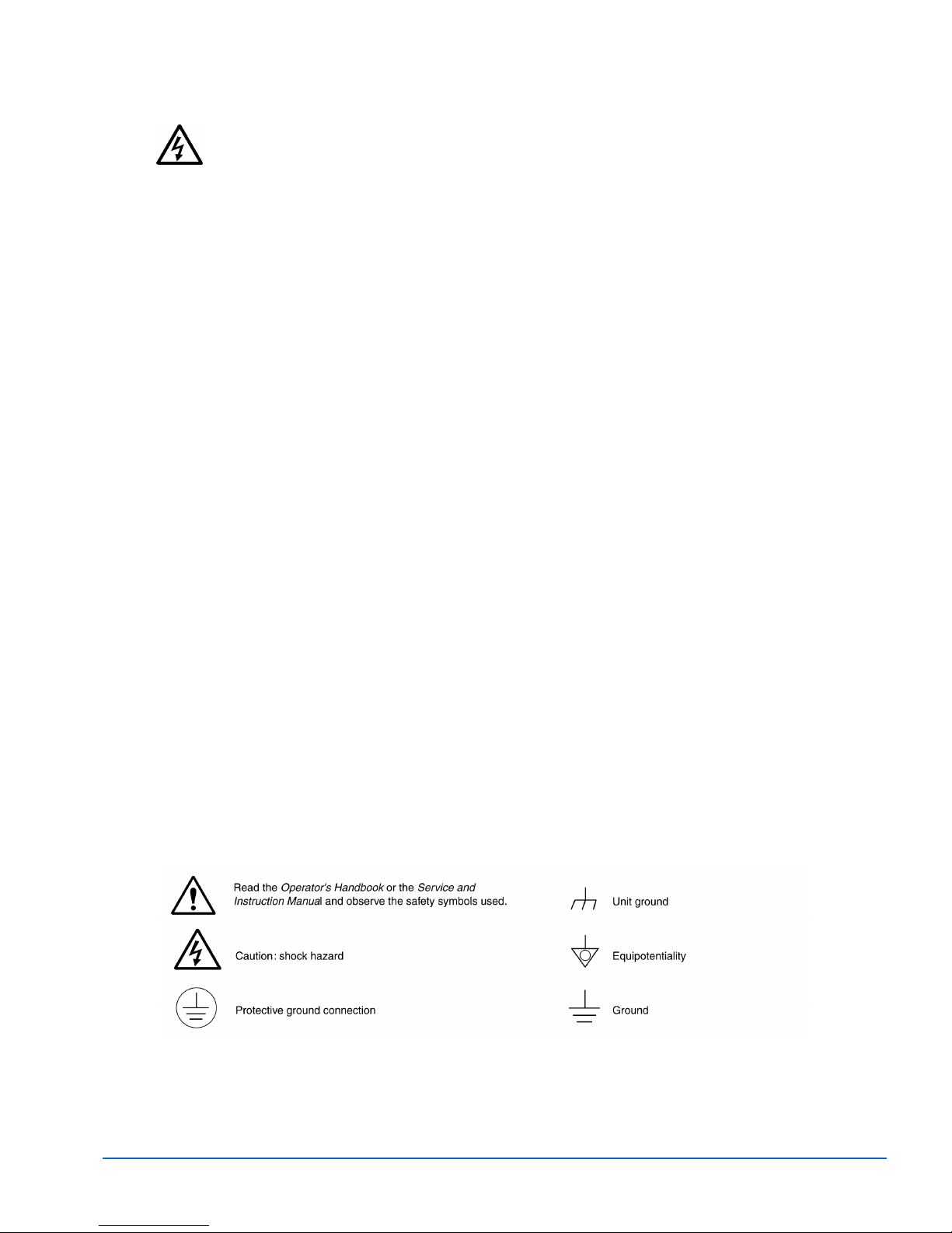
These symbols may appear on Videotek equipment:
Explanation of Symbols
OTM-20 Installation and Operation Handbook
Page 4

European Restriction on Hazardous Substance (RoHS), and Waste from
Electrical and Electronic Equipment (WEEE) Compliance
About This Document
This document provides information concerning Leitch Technology International, Inc. compliance with EU
Directive 2002/95/EC and EU Directive 2002/96/EC.
Restriction on Hazardous Substances (RoHS) Directive
Directive 2002/95/EC—commonly known as the European Union (EU) Restriction on Hazardous
Substances (RoHS)—sets limits on the use of certain substances found in electrical and electronic
equipment. The intent of this legislation is to reduce the amount of hazardous chemicals that may leach
out of landfill sites or otherwise contaminate the environment during end-of-life recycling. The Directive
takes effect on July 1, 2006, and it refers to the following hazardous substances:
• Lead (Pb)
• Mercury (Hg)
• Cadmium (Cd)
• Hexavalent Chromium (Cr-V1)
• Polybrominated Biphenyls (PBB)
• Polybrominated Diphenyl Ethers (PBDE)
In accordance with this EU Directive, all Leitch Technology products sold in the European Union will be
fully RoHS-compliant and “lead-free.” (See the Leitch Web site, www.leitch.com, for more information on
dates and deadlines for compliance.) Spare parts supplied for the repair and upgrade of equipment sold
before July 1, 2006 are exempt from the legislation. Leitch equipment that complies with the EU directive
will be marked with a RoHS-compliant symbol, as shown in Figure 1.
Figure 1. RoHS Compliance Symbol
WASTE FROM ELECTRICAL AND ELECTRONIC EQUIPMENT (WEEE)
DIRECTIVE
The European Union (EU) Directive 2002/96/EC on Waste from Electrical and Electronic Equipment
(WEEE) deals with the collection, treatment, recovery, and recycling of electrical and electronic waste
products. The objective of the WEEE Directive is to assign the responsibility for the disposal of associated
hazardous waste to either the producers or users of these products. Effective August 13, 2005, producers
or users will be required to recycle electrical and electronic equipment at end of its useful life, and must
not dispose of the equipment in landfills or by using other unapproved methods. (Some EU member
states may have different deadlines.)
In accordance with this EU Directive, Leitch Technology International, Inc. and other companies selling
electric or electronic devices in the EU will affix labels indicating that such products must be properly
recycled.
(See the Leitch Web site, www.leitch.com, for more information on dates and deadlines for compliance.)
Contact your local Leitch sales representative for information on returning these products for recycling.
Leitch equipment that complies with the EU directive will be marked with a WEEE-compliant symbol, as
shown in Figure 2.
OTM-20 Installation and Operation Handbook
Page 5

Figure 2. WEEE Compliance Symbol
OTM-20 Installation and Operation Handbook
Page 6

Blank Page
OTM-20 Installation and Operation Handbook
Page 7

Contents
Section 1 ♦ Introduction
Safety Information ................................................................................................................. 1-2
Safety Terms....................................................................................................................1-2
Service and Support.............................................................................................................. 1-3
Section 2 ♦ Installation
Inspecting the Shipment ....................................................................................................... 2-1
Connecting ............................................................................................................................ 2-1
Maintenance of Batteries ...................................................................................................... 2-2
Section 3 ♦ Operation
Panel ..................................................................................................................................... 3-1
GUI................................................................................................................................... 3-2
LCD Contrast ............................................................................................................... 3-2
Power Meter and Laser Source Interface.................................................................... 3-2
GUI Display.................................................................................................................. 3-3
Wavelength.................................................................................................................. 3-4
Menu Configuration and Measurement Operation................................................................ 3-4
Power Meter.....................................................................................................................3-5
W/dBm ......................................................................................................................... 3-5
Reference .................................................................................................................... 3-6
Precision ...................................................................................................................... 3-7
Average ....................................................................................................................... 3-8
Buzzer..........................................................................................................................3-9
Auto Trace ................................................................................................................. 3-10
Zero ........................................................................................................................... 3-12
Scale.......................................................................................................................... 3-13
Laser Source.................................................................................................................. 3-13
Laser On/Off .............................................................................................................. 3-14
Auto Test........................................................................................................................ 3-15
Recall ............................................................................................................................. 3-17
Clear............................................................................................................................... 3-18
Auto Off .......................................................................................................................... 3-19
Language ....................................................................................................................... 3-19
Set Default .....................................................................................................................3-19
Section 4 ♦ Data Collection Software
Introduction ........................................................................................................................... 4-1
OTM-20 Installation and Operation Handbook
i
Page 8

Contents
Software Installation.............................................................................................................. 4-1
Computer System Requirements..................................................................................... 4-1
Install the OTM-20 Upload Application Software............................................................. 4-1
Connecting ............................................................................................................................ 4-1
Software Operation ............................................................................................................... 4-1
GUI................................................................................................................................... 4-1
Menu and Tool Bar ...................................................................................................... 4-2
Upload Records ............................................................................................................... 4-3
Save Records .................................................................................................................. 4-4
Browse Stored Data......................................................................................................... 4-4
Printing Stored Data......................................................................................................... 4-5
Auto Trace Drawing ......................................................................................................... 4-6
Exit the Software.............................................................................................................. 4-7
Section 5 ♦ Troubleshooting
Maintenance and Replacing of Batteries .............................................................................. 5-1
Cleaning the Interfaces .........................................................................................................5-1
Calibration Requirements ..................................................................................................... 5-2
Appendix A ♦ Specifications
Power Meter Specifications ..................................................................................................A-1
Laser Source Module Specifications ....................................................................................A-1
Mechanical ............................................................................................................................ A-2
Environmental .......................................................................................................................A-2
Index
Figures
Figure 1-1. The OTM-20........................................................................................................... 1-2
Figure 2-1. OTM-20 Series Panel............................................................................................. 2-1
Figure 3-1. The Front OTM-20 Panel ....................................................................................... 3-1
Figure 3-2. Boot-up GUI of Optical Test Meter......................................................................... 3-2
Figure 3-3. Power Meter Interface............................................................................................ 3-2
Figure 3-4. Laser Source Interface........................................................................................... 3-3
Figure 3-5. Main Menu ............................................................................................................. 3-4
Figure 3-6. Power Meter Configuration Menu .......................................................................... 3-5
Figure 3-7. Unit of Measure Configuration ............................................................................... 3-6
Figure 3-8. Reference Configuration ........................................................................................ 3-6
Figure 3-9. Relative Measurement Menu ................................................................................. 3-7
Figure 3-10. Precision Configuration Menu.............................................................................. 3-8
Figure 3-11. Average Configuration Menu ............................................................................... 3-8
ii
OTM-20 Installation and Operation Handbook
Page 9

Contents
Figure 3-12. Buzzer Configuration............................................................................................ 3-9
Figure 3-13. Buzzer Max Configuration.................................................................................... 3-9
Figure 3-14. Auto Trace Configuration ................................................................................... 3-10
Figure 3-15. Auto Trace in Progress ...................................................................................... 3-10
Figure 3-16. Tracing Finished................................................................................................. 3-11
Figure 3-17. Auto Trace Curve ............................................................................................... 3-11
Figure 3-18. Zero Operation ................................................................................................... 3-12
Figure 3-19. Auto Zero Success............................................................................................. 3-12
Figure 3-20. Calibration Failure .............................................................................................. 3-13
Figure 3-21. Scale Configuration............................................................................................ 3-13
Figure 3-22. Laser Source Configuration ............................................................................... 3-14
Figure 3-23. Laser CW/MD Configuration .............................................................................. 3-14
Figure 3-24. Laser W/dBm...................................................................................................... 3-15
Figure 3-25. Auto Test Menu.................................................................................................. 3-15
Figure 3-26. Manual Configuration of Loss ............................................................................3-16
Figure 3-27. Auto Test in Process .......................................................................................... 3-16
Figure 3-28. Report of Auto Test Result................................................................................. 3-17
Figure 3-29. Recall Menu ....................................................................................................... 3-17
Figure 3-30. Recall Records................................................................................................... 3-18
Figure 3-31. Clear Menu.........................................................................................................3-18
Figure 3-32. Screen for Delete Record Confirmation ............................................................. 3-19
Figure 3-33. Set Default Confirmation GUI............................................................................. 3-20
Figure 4-1. OTM-20 Data Collection Software GUI.................................................................. 4-2
Figure 4-2. File Menu................................................................................................................ 4-2
Figure 4-3. Record Menu for Software ..................................................................................... 4-3
Figure 4-4. Draw Menu............................................................................................................. 4-3
Figure 4-5. Upload Records ..................................................................................................... 4-3
Figure 4-6. Sample Save Records GUI .................................................................................... 4-4
Figure 4-7. Open Saved File .................................................................................................... 4-5
Figure 4-8. Browse Saved Records.......................................................................................... 4-5
Figure 4-9. Printing Stored Data............................................................................................... 4-6
Figure 4-10. Power Auto Trace Interface.................................................................................. 4-6
Tables
Table 3-1. Description of the Front OTM-20 Panel .................................................................. 3-1
Table 3-2. Description of the GUI ............................................................................................. 3-3
OTM-20 Installation and Operation Handbook
iii
Page 10

Contents
Blank Page
iv
OTM-20 Installation and Operation Handbook
Page 11

Section 1 ♦ Introduction
NOTE: Please read the manual carefully before using any of the Harris fiber-optic instruments. Always
observe the warnings and cautions appearing throughout this manual. Bodily injury or damage to the
instrument can be caused when not following directions.
The Harris® OTM-20 Optical Test Meter is a new generation optical inspection tool.
This hand-held, intelligent, easy-to-use instrument is designed for fiber network
installation, verification, and routine inspection and maintenance. The OTM-20 has a
large memory capacity, and can transfer the testing data to a PC by associated software
for analyzing, graphic drawing, reporting, and printing previously stored data. Its
microprocessor and linear magnifying technology provides long-term stability. The
OTM-20 combines the function of the Laser Source (& Visible Laser) and the Power
Meter. It is ideal for both single-mode and multi-mode fiber checkouts.
This manual contains the information necessary for the proper operation and
maintenance of the Harris Optical Test Meters. It also provides troubleshooting and
service information.
The OTM-20 features are:
• Support quick test, intelligent operation
• Graphic interface on a large easy to read LCD display
• Bilingual operation (English and simplified Chinese)
• Multi-wavelength auto self-testing
• Relative/absolute power measurement
• Measures in dB, dBm, and mW
• Large memory capacity (4000 measurements)
• RS-232 data upload port, and PC software for previously stored data analyzing,
graphic drawing, and reporting
• Both continuous wave (CW) and modulated frequency modes
• Optical connector with dual-wavelength output
• Supports auto test of optic fiber loss
• Plotted power value graph
• Optical power alarm
• Automatically store data
• Damp, dust, and shock proof design
• Powered by a NiMH battery or Power adapter with auto recharging
• Interchangeable fiber-optic connectors (FC/PC, or optional SC, ST)
• Battery level indicator and auto recharging display
• Auto off function conserving battery life
OTM-20 Installation and Operation Handbook
1-1
Page 12
Introduction
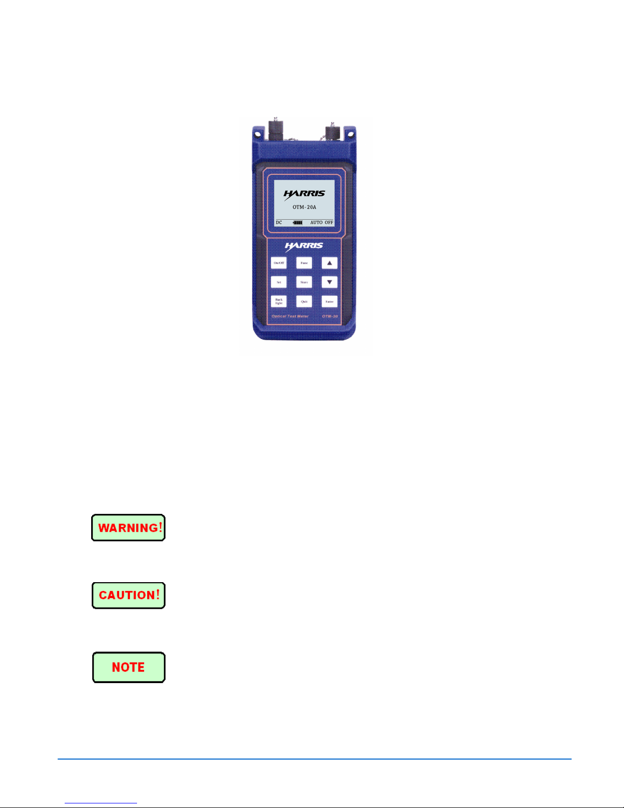
The OTM-20 is illustrated in Figure 1-1.
Figure 1-1. The OTM-20
Safety Information
Please observe the following general safety precautions at each stage when using these
instruments. Violation of the safety standards of the instruments will occur if such
safety precautions are not adopted or the user fails to obey the special warning in other
parts of this manual. Harris will not take any responsibility for the results caused by
not following these requirements.
Safety Terms
WARNING identifies any procedure or practice that if not followed could result in
serious injury.
CAUTION identifies any procedure or practice that if not followed could result in
damage to the instrument or serious injury.
NOTE identifies information that may be beneficial during the use and maintenance of
the instrument.
1-2
OTM-20 Installation and Operation Handbook
Page 13
The Optical Test Meter is a laser instrument. Users should avoid looking directly into
the optical output. And the use of a microscope or magnifier should also be avoided,
for the use of such devices can focus a highly intense beam onto the retina that may
result in permanent eye damage.
Battery: The battery for this instrument is a rechargeable NiMH battery. If unused for
a long time, the battery should be recharged before being used. If the instrument is left
idle for more than two months, it should be recharged to maintain adequate power
volume.
Battery Power: Do not recharge batteries for more than 8 hours. Do not take batteries
out without the assistance of authorized personnel help. Do not expose batteries to fire
or intense heat. Do not open or mutilate batteries. Avoid touching the electrolyte on the
batteries, which is corrosive and may cause injuries to eyes or skin, or damage to
clothes.
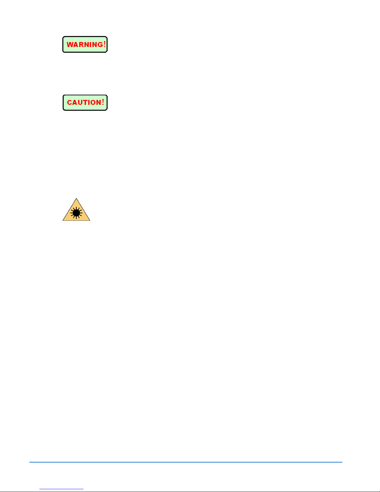
Fiber Optic Laser Source
Laser Radiation: To avoid serious eye injury, never look directly into the
optic outputs of the fiber optic network equipment, test equipment, patch cords, or test
jumpers.
• Always avoid looking directly into the optic output port. The emitted laser is a
non-visible laser.
• Always replace protective dust caps on the detector port when the instrument is not
being used.
Protective Sleeve: Keep the soft plastic sleeve on the OTM-20 to avoid possible
damage.
Service and Support
Upon receiving the instrument, please check for any obvious signs of physical damage
that may have occurred during shipment. Report any damage to the shipping agent or
the representative of Videotek immediately. Retain the original packing materials if
reshipment becomes necessary.
For service and support, telephone the Customer Service Department at 610-327-2292.
If the problem cannot be resolved over the telephone and the instrument must be
shipped to Videotek for service or repair:
• Obtain a Return Authorization (RA) number from the Videotek Customer Service
Department.
• Attach a tag to the unit with:
− Your company name, address, and telephone number
− The name of the contact person at your company
− The RA number
OTM-20 Installation and Operation Handbook
1-3
Page 14

Introduction
− The unit serial number
− An explanation of the problem
• To prevent shipping damage, pack the unit the same way Videotek had packed it.
If possible, use the original packing materials in the original shipping container.
• Ship the unit to:
Videotek, Inc.
243 Shoemaker Road
Pottstown, PA 19464-6433
Attn: Service Dept.
1-4
OTM-20 Installation and Operation Handbook
Page 15

Section 2 ♦ Installation
This section provides information about inspecting and configuring the OTM-20.
Inspecting the Shipment
The OTM-20 is carefully assembled and undergoes a rigorous mechanical, electrical,
and optical inspection prior to shipment.
Inspect the box and the contents. Report any damage to the shipper and telephone the
Videotek Customer Service Department for service and support (see Section 1,
“Service and Support”).
NOTE: Refer to the enclosed packing sheet for the latest list of items that are supplied with the unit.
The box contains the following:
• One OTM-20 with protective sleeve
• One OTM-20 Installation and Operation Handbook
• AC adapter/charger
• Soft carrying case with belt strap
• RS232 cable/adapter
• Shoulder strap that attaches to the protective sleeve
• CD-Rom software
Save the box and packing material for any future shipping requirements.
Connecting
The panel connectors are illustrated in Figure 2-1.
Figure 2-1. OTM-20 Series Panel
Power Adapter Jack
Power adapter jack requirements: 13.8V DC @ 1.2A
OTM-20 Installation and Operation Handbook
2-1
Page 16

Installation
Optical Power Test Input
The fiber optic power metering input used to receive optical signal. It is a Fiber Optic
FC/PC connector. Optional SC/ST connectors available.
RS-232 Data Port
This interface is used to upload stored measurement records to the PC data collection
software for further analysis, statistics, and reporting.
CAUTION: Avoid looking directly at the optic output. The laser is a non-visible laser.
Maintenance of Batteries
The battery used for the Harris OTM-20 is the NiMH battery.
Cautions during Operation:
Auto Power Off occurs under the following conditions:
• The instrument will be auto power off when there is insufficient power during
operation and low power will be shown on the LCD.
• The Auto Off function is active and shuts down the device after being idle for 5
minutes.
Cautions in Recharge:
• When the AC adapter is applied, the OTM first performs a quick charge. After the
Quick charge is performed, the OTM automatically switches to trickle charge after
the voltage reaches a predefined parameter. The battery can be damaged if the
operating temperature range is exceeded during charging.
• Do not charge for over eight hours.
2-2
OTM-20 Installation and Operation Handbook
Page 17

Section 3 ♦ Operation
Panel
The OTM-20 Series is shown in Figure 3-1.
Figure 3-1. The Front OTM-20 Panel
Table 3-1. Description of the Front OTM-20 Panel
Name Description
On/Off
Func
Set
Store
Backlight
Quit
Enter
[ ] and [ ]
This button turns the instrument on and off. After the unit is powered on,
under the default state, the OTM-20 automatically shuts down when buttons
have not been pressed for five minutes and not performing Auto Trace.
Press to toggle between the Laser Source interface and the Power Meter
interface.
Press to enter the Main menu. The Main menu is used to configure system
parameters.
Saves measurements and results from auto test.
Turns the LCD backlight on. Press and the light will last for approximately ten
seconds.
Exit all auto tests and menus, and return to the Graphical User Interface
(GUI).
Selects the highlighted parameter.
This button has several functions: On the Startup screen, it is used to adjust
the LCD contrast. In the system menu it scrolls through the menu items and
menu values. Under the Laser Source and Power Meter mode, it is used to
switch the wavelength.
OTM-20 Installation and Operation Handbook
3-1
Page 18

Operation
GUI
LCD Contrast
After powering on, the Graphical User Interface (GUI) will be displayed, as shown in
Figure 3-2.
Figure 3-2. Boot-up GUI of Optical Test Meter
The surrounding temperature will affect the LCD contrast. Contrast can be adjusted by
pressing the button through the following procedures.
• Power on the instrument, the GUI is displayed (as shown in Figure 3-2).
• Press the button and the contrast will be increased. Press button and the
contrast will be reduced.
Power Meter and Laser Source Interface
Press FUNC and the instrument will enter the Power Meter interface, as shown in
Figure 3-3.
Figure 3-3. Power Meter Interface
Press FUNC again to switch between the Power Meter interface and the Laser Source
interface. The Laser Source interface is shown in Figure 3-4.
3-2
OTM-20 Installation and Operation Handbook
Page 19

Operation
Figure 3-4. Laser Source Interface
GUI Display
As shown in Figure 3-3 and Figure 3-4, the GUI Display contains the items described
in Table 3-2.
Table 3-2. Description of the GUI
Key
1
2
3
4
5
Name Description
Wavelength Wavelength of the selected function: Laser Souce or Power Meter.
Power Value
Display
Modulation
Frequency
Scale In the power meter mode, the bar is used to display the power level
DC Batteries power the instrument. When the instrument is powered by the
In the Laser Source mode, “Laser Off” or the output power value will be
displayed. In the Power Meter mode, a series of “-“ or the measured
input power value will be displayed.
In the Laser Source mode, the modulation frequency (or CW) will be
displayed. In the Power Meter mode, the modulation frequency of 270,
1000, or 2000 Hz will be displayed (if the modulation is present).
above and below the reference value. “
value. The ± value indicates the selected scale, which is the maximum
and minimum indication above and below the reference value.
rechargeable batteries, the charge volume of the batteries is shown on
the LCD:
” indicates the reference
OTM-20 Installation and Operation Handbook
(Table continues on next page)
3-3
Page 20

Table 3-2. Description of the GUI (continued)
Operation
5 (cont)
6
AC (not shown) The instrument is powered through an AC/DC adapter. When the
instrument is powered on and powered through the AC/DC adapter, the
batteries are automatically recharged. The battery symbol on the LCD
indicates charge status:
Auto Off This is the Auto Off enable indication. After powering on, the Auto-Off
function default status is enabled. If no buttons have been pressed for 5
minutes, the instrument will automatically turn off for the benefit of
conserving battery life.
Wavelength
In the Power Meter or Laser Source modes, the wavelength can be changed by pressing
[ ] and [ ].
Menu Configuration and Measurement Operation
When in the GUI, press the SET button to enter the Main Menu, as shown in
Figure 3-5.
Figure 3-5. Main Menu
Press the
button to scroll through the currently activated menu bar, then press the
ENTER button to enter the activated sub menu. Press the QUIT button to return to a
higher-level menu.
The Main Menu includes the following menu selections:
Power Meter
Laser Source
Auto Test
Recall
3-4
OTM-20 Installation and Operation Handbook
Page 21

Operation
Clear
Auto Off
Lang.
Set Default
Auto test is only applicable to a long distance single-mode optical
fiber.
Power Meter
When in the GUI, press SET to enter the Main Menu. Use the [ ] to scroll
through the menu bar to select Power Meter. Press ENTER. The display is shown in
Figure 3-6.
Figure 3-6. Power Meter Configuration Menu
The Power Meter menu includes the menu selections:
W/dBm
Reference
Precision
Average
Buzzer
Auto Trace
Zero
Scale
After the configuration is complete, press the QUIT button to exit to the main menu.
W/dBm
In the Power Meter menu, press the [
] buttons to scroll through the menu bar to
select W/dBm, and press the ENTER button to enter the configuration shown in
Figure 3-7. Use the [ ] buttons to scroll through the menu bar to select the item.
Press ENTER to confirm. The selected unit of measure is marked with “*”.
OTM-20 Installation and Operation Handbook
3-5
Page 22

Operation
After selecting the menu item, press QUIT to exit to the higher-level menu. The
selection is saved after the unit is powered off.
Figure 3-7. Unit of Measure Configuration
“dBm” is set as the default. “W” includes: “mW,” “uW,” “nW,” and
“pW.” When “W” is selected, the optical test meter will choose the unit of measure to
display automatically.
Reference
In the Power Meter menu, press the [ ] buttons to scroll through the menu bar
and select “Reference.” Press ENTER to enter the configuration as shown in
Figure 3-8. The selections are not saved and return to the default value after the
device is powered off.
Figure 3-8. Reference Configuration
Under this configuration menu, there are three function menus: “DRef,” “Ref Value,”
and“Ref:”
DReF
Ref Value
3-6
Set current tested power value as the relative
reference value.
Set the relative reference value
OTM-20 Installation and Operation Handbook
Page 23

Operation
Ref
Reference ON/OFF
DRef: Under the DRef menu, press [ ] to scroll through the menu bar to select
DRef. Press ENTER to set the current power value as the reference value.
After the configuration is complete, press QUIT to exit to the higher-level menu.
Ref Value: Under the RefValue menu, press [ ] to scroll the menu bar to select
Ref Value. Press ENTER to enter the configuration. The reference value can be
adjusted by pressing [ ]. When the final desired value is reached, press ENTER
to confirm and set the adjusted value as the current reference value. After the
configuration is complete, press QUIT to exit to the higher-level menu.
Ref: Under the Reference menu, press [ ] to select Ref On/Off, and press
ENTER to activate or deactivate the relative measurement. When “*” appears, the
function is activated. When “*” disappears, the function is deactivated. A sample
screen is shown in Figure 3-8. After the configuration is complete, press QUIT to exit
to the higher-level menu.
Relative Measurement: Press [ ] to select Ref On/Off, and press ENTER to
activate the reference measurement. Press QUIT to exit level by level. The relative
measurement is now displayed, and the unit of measurement is dB, as shown in
Figure 3-9.
Figure 3-9. Relative Measurement Menu
To disable relative measurement, press SET to enter the main menu, deactivate
Reference in the Power Meter mode, and then press QUIT to exit level by level. The
Absolute Measurement is now displayed, as shown in Figure 3-3.
Precision
There are three precision selections, as shown in Figure 3-10: “0.1dB,” “0.01dB,” and
“0.001dB.”
OTM-20 Installation and Operation Handbook
3-7
Page 24

Operation
Figure 3-10. Precision Configuration Menu
When in Power Meter menu, press [ ] to scroll the menu bar until Precision is
highlighted. Press ENTER to confirm and enter the Precision menu (as shown in
Figure 3-10). Press [ ] to scroll the menu bar and highlight the Precision unit
for the power value display. Then, press ENTER for confirmation. “*” indicates the
selected menu item. After the configuration is set, press QUIT to back to the
higher-level menu. The selection is saved after the unit is powered off.
“0.01dB”is the default value.
Average
The Average menu has the following menu selections: “Average Off,” “10 Samples,”
“50 Samples,” and “100 Samples,” as shown in Figure 3-11.
Figure 3-11. Average Configuration Menu
In Power Meter menu, press [
] to scroll the menu bar until Average is
highlighted. Press ENTER to confirm and enter the Average menu. Press [ ] to
scroll the menu bar and highlight the average time. Press ENTER for confirmation.
“*” indicates the selected menu item. After the configuration is set, press QUIT to exit
to the higher-level menu. The selections are not saved to memory, and will return to the
default value after the unit is powered off.
“Average Off” is the default.
3-8
OTM-20 Installation and Operation Handbook
Page 25

Operation
Buzzer
The buzzer is designed to test the stability of the optical fiber power. When the input
power exceeds the selected Max and Min values the buzzer automatically gives an
alarm when enabled.
In the Power Meter menu, press [ ] to scroll the menu bar until “Buzzer” is
highlighted. Press ENTER to confirm and enter the Buzzer menu. There are three
menu selections: “Max,” “Min,” and “Buzzer,” as shown in Figure 3-12. The
selections are not saved to memory and will return back to the default value after the
unit is powered off.
Figure 3-12. Buzzer Configuration
• Buzzer Max: Under the Buzzer menu, press [ ] to highlight the menu bar
and select “Max,” and press ENTER for confirmation to enter the Buzzer Max
menu as shown in Figure 3-13.
Press [ ] to change the Max parameter (default set to begin with the last
parameter). When the desired Max value is reached, press ENTER to confirm and
exit to the higher-level menu.
Figure 3-13. Buzzer Max Configuration
• Buzzer Min: The Buzzer Min specific operation process is similar to Buzzer Max;
please refer to the above procedures.
• Buzzer On/Off: In the Buzzer menu, press [ ] to select “Buzzer On/Off.”
Press ENTER to activate or deactivate the buzzer. When “*” appears, it means the
OTM-20 Installation and Operation Handbook
3-9
Page 26

Operation
buzzer is activated. After the configuration is set, press QUIT to back to the
higher-level menu.
“Buzzer Off” is the default.
Auto Trace
The Auto Trace function records power variations in the optical fiber for the selected
duration. It then draws the power variation curve.
• Activate Auto Trace: For the proper implementation of the auto trace function, a
Dref point is needed to be set first (For specific configuration, please refer to
Reference on page 3-6), which will be the scale for the power variation curve.
Set the reference to display an indication on the bar graph.
After the above setting is established, select Auto Trace in Power Meter menu to enter
the Auto Trace menu, as shown in Figure 3-14.
Figure 3-14. Auto Trace Configuration
A different trace time can be chosen by pressing [ ] and then pressing ENTER
to confirm. After the trace time is selected, the instrument will start auto tracing, as
shown in Figure 3-15.
Figure 3-15. Auto Trace in Progress
3-10
OTM-20 Installation and Operation Handbook
Page 27

Operation
• Terminate Auto Trace: The applications can be terminated at any time during the
auto trace progress by pressing the QUIT button. Pressing the QUIT button
returns to the Power Meter menu, shown in Figure 3-6.
• Auto Trace Finish and Draw Power Variation Curve: When the instrument
finishes auto tracing, “Finished!” is indicated on the screen, as shown in
Figure 3-16.
Figure 3-16. Tracing Finished
After Auto Trace is complete, press the QUIT button to back out to the Auto Trace
configuration menu (as shown in Figure 3-14), or press ENTER to draw the power
variation curve, as shown in Figure 3-17.
Figure 3-17. Auto Trace Curve
The dynamic range for the instrument’s auto trace curve is the selected
scale. Any value beyond the scale will not be displayed. The trace can be uploaded to
the PC for storage and printing.
Only one auto trace curve can be stored in the OTM memory. If the
screen is to be saved, DO NOT push the STORE button again until the screen is
downloaded to the PC, otherwise the screen will be lost. The activation of another auto
trace will overwrite the trace already in memory. A viewable auto trace can only be
achieved if the reference parameters are set and there is a level response in the bar on
OTM-20 Installation and Operation Handbook
3-11
Page 28

Operation
the Power Meter GUI. This also requires the Laser Source to be activated if the OTM
Laser Source was used prior to the auto trace activation.
Zero
The Zero function is used to Auto Calibrate the Power Meter. Replace the protective
cap on the optical power testing input. After the power is on, enter the Power Meter
menu and press [ ] to scroll the menu selection to highlight Zero. Then, press
ENTER to confirm the selection and begin the auto calibration process, as shown in
Figure 3-18.
Figure 3-18. Zero Operation
After the auto calibration, the display will be as shown in Figure 3-19.
Figure 3-19. Auto Zero Success
If the input is not completely enclosed, it may cause calibration failure, as shown in
Figure 3-20. Calibration must be successful for general operation.
3-12
OTM-20 Installation and Operation Handbook
Page 29

Figure 3-20. Calibration Failure
Scale
Operation
In the Power Meter menu, press [
] to select Scale. Press ENTER to enter the
Scale Configuration, as shown in Figure 3-21. The four Scale selections are: ±0.5 dB,
±1.0 dB, ± 1.5 dB, and ± 2.0 dB. Press [
] to select a different scale and press
the ENTER button to accept the selection. “*” indicates the selected menu item. Once
the scale is changed, the scale displayed on the screen will change immediately. After
the configuration is selected, press QUIT to back out to the higher-level menu. The
selections are not saved to memory and return back to the default value after the unit is
powered off.
Figure 3-21. Scale Configuration
Laser Source
Under the GUI, press SET to enter the Main menu. Use [ ] to scroll through the
menu and highlight Laser Source. Press ENTER to enter the Laser Source menu, as
shown in Figure 3-22. After configuration is established, press the QUIT button to
exit to the Main menu.
OTM-20 Installation and Operation Handbook
3-13
Page 30

Figure 3-22. Laser Source Configuration
Laser On/Off
Operation
In the Laser Source menu, as shown in Figure 3-22, press [
] to highlight Laser
On/Off and press ENTER to activate or deactivate the laser function. “*” indicates the
selected menu item. After the configuration is set, press the QUIT button to back out
to the higher-level menu. The selections are not saved to memory and return back to
the default value after the unit is powered off.
CW/MOD
In the Laser Source menu, as shown in Figure 3-22, press [ ] to scroll and
highlight CW/MOD. Press ENTER to access the Laser CW/MOD menu, as shown in
Figure 3-23. Press [ ] to scroll and select the desired mode, and then press
ENTER to accept the selection. “*” indicates the selected menu item. After the
configuration is set, press the QUIT button to exit to the higher-level menu. The
selections are not saved to memory and return back to the default value after the unit is
powered off.
Figure 3-23. Laser CW/MD Configuration
The default set is CW (continuous wave).
3-14
OTM-20 Installation and Operation Handbook
Page 31

Operation
W/dBm
In the Laser Source menu, as shown in Figure 3-22, press [ ] to scroll and
highlight W/dBm. Press the ENTER button to access the Laser W/dBm menu, as
shown in Figure 3-24. Press [ ] to scroll and select the desired unit, and press
ENTER to accept the selection. “*” indicates the selected menu item. After the
configuration is set, press the QUIT button to exit to the higher-level menu. The
selection is saved to memory after the unit is powered off.
Figure 3-24. Laser W/dBm
The default selection is dBm.
Auto Test
The instrument can perform loss testing of the optical fiber and make an estimation of
the optical fiber length. Loss per kilometer is used to calculate the fiber length.
• Enter Auto Test Menu: In the main menu, press [ ] to scroll and highlight
Auto Test. Press the ENTER button to access the Auto Test configuration menu,
as shown in Figure 3-25.
Figure 3-25. Auto Test Menu
• Manually Set Loss: Users can precisely configure the loss of the 1310nm and
1550nm wavelength, so as to increase the accuracy of the optical fiber length.
OTM-20 Installation and Operation Handbook
3-15
Page 32

Operation
Under the Auto Test menu, press [ ] to scroll the menu selections to select
1310nm or 1550nm, and press the ENTER button to access the menu, as shown in
Figure 3-26. Press (or press and hold) [ ] to change the value. After the
value reaches the desired parameter, press ENTER to confirm. The selections are
not saved and return back to the default value after the unit is powered off.
Figure 3-26. Manual Configuration of Loss
• Default: The default loss of this instrument is: 0.40dB/km for 1310nm and
0.25dB/km for 1550nm. In the Auto Test menu, press [
] to scroll the menu
bar and select Default. Press ENTER for confirmation. The loss will be set to
Default.
• Activate Auto Test: In the Auto Test menu, press [ ] to select Start Test,
and then press ENTER for confirmation. The optical test meter will start the auto
test. The test in-process screen is shown in Figure 3-27. The test takes
approximately five minutes to complete, or press the QUIT button to terminate the
operation without results.
Figure 3-27. Auto Test in Process
• Auto Test Report: After the completion of the Auto Test, the instrument screen
will display the report of the auto test result, as shown in Figure 3-28. Browse the
test results in the1310nm and 1550nm wavelength by pressing [ ].
3-16
OTM-20 Installation and Operation Handbook
Page 33

Operation
Figure 3-28. Report of Auto Test Result
To save the Auto Test Data for PC uploading, push the STORE button. Only one
information screen is saved per file memory. To save the 1310 and 1550 information,
push the STORE button for each screen. When STORE is pushed, the memory file
number is flashed on the screen for .5 seconds.
Press QUIT to exit the test results screen. At this point, the Test Results screen can no
longer be saved. Press QUIT again to return to the Main Menu.
Auto test is only applicable to long-distance, single-mode optical fiber.
Recall
Recall is used to review stored wavelength measurements of 850nm, 1300nm, 1310nm,
1550nm, and auto test. In the main menu, press [ ] to select Recall. Press the
ENTER button to access the Recall menu, as shown in Figure 3-29.
Figure 3-29. Recall Menu
In the Recall menu, press [
test”) and press
ENTER to enter the submenu. The screen will display the stored
records of this wavelength (or “auto test”). Browse all stored records by pressing
[ ], as shown in Figure 3-30. After completion, press the QUIT button to exit
to the higher-level menu.
] to select the corresponding wavelength (or “auto
OTM-20 Installation and Operation Handbook
3-17
Page 34

Operation
Figure 3-30. Recall Records
Clear
Clear is used to clear or delete wavelength measurements for 850nm, 1300nm,
1310nm, 1550nm, or auto test. In the main menu, press
Press the ENTER button to access the Clear menu, as shown in Figure 3-31
[ ] to select Clear.
Figure 3-31. Clear Menu
Under the Clear menu, press [
] to select the corresponding wavelength or auto
test, and press ENTER to enter the Delete Record menu, as shown in Figure 3-32.
Select YES and ENTER for confirmation. All stored records of the selected
wavelength or auto test will be deleted and then automatically return to the CLEAR
menu.
3-18
OTM-20 Installation and Operation Handbook
Page 35

Operation
Figure 3-32. Screen for Delete Record Confirmation
Auto Off
The instrument has an Auto-Off function. When this function is activated, and no
buttons have been pressed for five minutes, the instrument will automatically turn off
to conserve battery life.
Under the main menu, press the [ ] button to select Auto Off, and press ENTER
to activate or deactivate the Auto-Off function. When “*” appears, the Auto-Off
function is ON. After the selection is made, press the QUIT button to exit to the main
menu. The selections are not saved to memory and return back to the default value
after the unit is powered off.
The default setting for Auto-Off is ON.
Language
The instrument supports both a Chinese and English display. When a selection is
made, the instrument will memorize this selection and automatically display the
selected language the next time the device is powered-on.
In the Main menu, press the [ ] button to select the Language menu item, then
press the ENTER button to switch between English and Chinese. After the selection is
made, press QUIT to exit to a higher level menu.
Set Default
Set Default is used to set the default values for all parameters and configurations of this
instrument. In the main menu, press the [ ] button to select SET DEFAULT.
Press the ENTER button to access the Set Default interface, as shown in Figure 3-33.
After selecting YES or NO, press ENTER to confirm. The instrument will perform the
relevant operation and exit to the main menu.
OTM-20 Installation and Operation Handbook
3-19
Page 36

Figure 3-33. Set Default Confirmation GUI
Operation
3-20
OTM-20 Installation and Operation Handbook
Page 37

Section 4 ♦ Data Collection Software
Introduction
The OTM-20 upload application is software that allows the stored measurement
records in the instrument to be uploaded to a PC through an RS-232 port to be
displayed, saved, or printed. The data saving format is compatible with Microsoft®
Excel. All stored records can be browsed, edited, and printed with Excel.
Software Installation
Computer System Requirements
• CPU: Pentium or above
• Operating System: Microsoft
• Internal Memory: 64MB or above
®
Windows 98/2000/XP
• Hard Disk: 10MB or above (exclude the space of the operating system)
• CD-ROM: 8 speed or above
• RS-232 serial port: at least one 9-pin series port
Install the OTM-20 Upload Application Software
1. Start Windows 98/2000/XP. If Windows 98/2000/XP is running, please quit all the
other applications.
2. Insert the installation disc into the CD-ROM drive.
3. Double-click SETUP.EXE to install.
4. The installation is similar to other Windows application software. Follow the
instructions on the installation wizard step-by-step until the installation is
completed.
Connecting
Power off the instrument, and connect the provided RS-232 cable to the device and the
PC. Power on the instrument.
Software Operation
GUI
After the installation of the OTM-20 upload application, double-click the Launch
OTMupload shortcut on the desktop or select
START\PROGRAMS\HARRIS\HARRIS OTM UPLOAD APPLICATION
SYSTEM\LAUNCH OTMupload.exe, and the GUI will appear, as shown in
Figure 4-1.
OTM-20 Installation and Operation Handbook
4-1
Page 38

Data Collection Software
Figure 4-1. OTM-20 Data Collection Software GUI
Menu and Tool Bar
On the main screen select the COM port where the device is located.
Click FILE. The File menu appears, as shown in Figure 4-2. The File menu items are:
• Upload: Click the UPLOAD menu selection to upload measurement records.
• Open: Open a saved data file to browse the previous measurement results.
• Close: Close the file.
• Save: Save the data.
• Print: Print the data.
• Exit: Exit the OTM-20 upload application.
Figure 4-2. File Menu
Click RECALL. The Recall menu, as shown in Figure 4-3, is used to select the data to
be uploaded. The Recall menu items are:
• STORE RECORD: Select the stored records of different wavelengths.
• AUTO TEST RECORD: Selects the Auto Test Records.
• AUTO TRACE RECORD: Selects the Auto Trace Records.
4-2
OTM-20 Installation and Operation Handbook
Page 39

Data Collection Software
Figure 4-3. Record Menu for Software
After opening a saved trace file or uploading an auto trace, click DRAW. The Draw
menu appears, as shown in Figure 4-4. The Draw menu items are:
• Scale=±1.0dB: Selects the data scale within ±1.0dB when the curve is drawn.
• Scale=±2.0dB: Selects the data scale within ±2.0dB when the curve is drawn.
• Scale=±3.0dB: Selects the data scale within ±3.0dB when the curve is drawn.
• Scale=±4.0dB: Selects the data scale within ±4.0dB when the curve is drawn.
Figure 4-4. Draw Menu
Upload Records
Click the UPLOAD (RS-232 plug icon) button to start automatically uploading the
selected records determined by the Recall menu. The sample screen is shown in
Figure 4-5.
Figure 4-5. Upload Records
OTM-20 Installation and Operation Handbook
4-3
Page 40

Data Collection Software
Save Records
After completing the uploading and filling out all the necessary information, click the
SAVE (disk icon) button or Save menu from the File menu and select or type a file
name. The Save Records dialog box will display, as shown in sample Figure 4-6.
• Date: Automatically set according to the PC’s internal setting.
• Time: Automatically set according to the PC’s internal setting.
• Cable: Fill in the number of the cable under test.
• From: Fill in the starting point of the cable under test.
• To: Fill in the destination of the cable under test.
• Company: Fill in the name of the company.
• Operator: Fill in the name of the operator.
• Location: Fill in the location of fiber.
Figure 4-6. Sample Save Records GUI
Browse Stored Data
Stored data can be reopened, browsed, and reviewed. Click the OPEN (folder icon)
button. Select a file from the OPEN dialog box and click the OPEN button, as shown
in Figure 4-7.
4-4
OTM-20 Installation and Operation Handbook
Page 41

Figure 4-7. Open Saved File
Data Collection Software
Click OPEN. The records will display, as shown in Figure 4-8. Users can browse the
records. To close the opened file, click CLOSE (folder with arrow icon) button.
Figure 4-8. Browse Saved Records
Printing Stored Data
After uploading or opening a stored record file, click the PRINT (printer icon) button.
The Printer Dialog appears, as shown in Figure 4-9.
OTM-20 Installation and Operation Handbook
4-5
Page 42

Figure 4-9. Printing Stored Data
Auto Trace Drawing
Data Collection Software
After uploading the auto trace records or opening the stored auto trace records file,
click the Draw\Auto Trace Drawing menu selection. The software will draw the auto
trace curve in a new window, as shown in Figure 4-10.
Figure 4-10. Power Auto Trace Interface
In the figure:
Max.: The maximum value of the records.
Min.: The minimum value of the records
Avg.: The average value of the records.
Ref.: The reference value (set to the 0.0 value in the graph)
4-6
OTM-20 Installation and Operation Handbook
Page 43

Data Collection Software
Click the Scale selection to change the dynamic range of the Y-axis. Single-click the
REDRAW button to redraw the curve for the new scale selection. Single-click the
PRINT button to print the displayed curve. Single-click the CLOSE button to close the
displayed curve drawing window.
Exit the Software
Select the EXIT menu item to close the File menu and exit the application.
OTM-20 Installation and Operation Handbook
4-7
Page 44

Data Collection Software
Blank Page
4-8
OTM-20 Installation and Operation Handbook
Page 45

Section 5 ♦ Troubleshooting
CAUTION — these instructions are for use by qualified personnel only. To reduce
the risk of electric shock, do not perform this installation or any servicing unless you
are qualified to do so. Refer all servicing to qualified service personnel.
Maintenance and Replacing of Batteries
The battery for the Harris OTM-20 is a rechargeable NiMH battery. All the NiMH
batteries have been correctly installed and factory tested. Please do not open the
instrument to replace batteries.
• If the instrument is left unused for a long time (idle for over 1 month), it is
recommended to recharge the battery every other month
• Do not charge the battery for more than 8 hours, or permanent damage may occur.
Cautions during Operation:
Auto Power Off occurs under the following conditions:
• The instrument will be auto power off when there is insufficient power during
operation and low power will be shown on the LCD.
• The Auto Off function is active and shuts down the device after being idle for 5
minutes.
Cautions in Recharge:
• When the AC adapter is applied, the OTM first performs a quick charge. After the
Quick charge is performed, the OTM automatically switches to trickle charge after
the voltage reaches a predefined parameter. The battery can be damaged if the
operating temperature range is exceeded during charging.
• Do not charge for over eight hours.
Cleaning the Interfaces
Proper cleaning should be performed before conducting any tests. A
lint-free cloth and reagent-grade isopropyl alcohol should be used to
clean the interfaces. Always replace protective dust caps when the
unit is not in use, and keep the protective dust caps clean.
Dirty connectors will cause performance degradation as follows:
• Measurement errors
• Linear errors
• Attenuation in optical power
• Optical power received may be out
OTM-20 Installation and Operation Handbook
5-1
Page 46

Troubleshooting
Calibration Requirements
Calibration is recommended every three years. Please contact Videotek Customer
Service.
5-2
OTM-20 Installation and Operation Handbook
Page 47

Appendix A ♦ Specifications
Power Meter Specifications
Measurement Range (dBm)
Wavelength (nm)
Detector Type
Accuracy
Resolution
Data Storage
-70 ~ + 10 for model A
-50 ~ + 27 for model C
850, 1300, 1310, 1550 for model A
980, 1310, 1480, and 1550 for Model C
InGaAs
±0.25 dB @ 25°C & -10dBm
0.001 dB
4000 Measurements
Laser Source Module Specifications
Emitter Type
Wavelength (nm)
Output Power
Spectral Width (nm)
Stability
Modulation Frequency
Connector Type
LD
1310/1550
≥ -7 dBm
≤ 5
Short Time: ±0.05 dB/15 min
Long Time: ±0.10 dB/8 hr @ 1310/1550nm
270/1K/2KHz
FC/PC (input only SC, ST)
OTM-20 Installation and Operation Handbook
A-1
Page 48

Specifications
Mechanical
Dimensions
Weight
Height: 8.8" (22 cm)
Width: 4.4" (11.2 cm)
Depth: 2.3" (6 cm)
2.0 lbs (0.88 kg)
Environmental
Operating temperature
Storage temperature
Humidity
0° to +50°C
-20° to +70°C
10 to 90% (non-condensing)
Specifications are subject to change without notice.
A-2
OTM-20 Installation and Operation Handbook
Page 49

Index
A
Auto Off, 3-19
Auto Test, 3-15
Auto Trace, 3-10
Curve Configuration, 3-11
AVerage, 3-8
B
Battery
Maintenance, 5-1
Replace, 5-1
Battery Maintenance, 2-2
NiMH, 2-2
Recharge, 2-2, 5-1
Browse Saved Records, 4-5
Buzzer, 3-9
C
Specifications, A-2
F
File Menu, 4-2
Front Panel, 1-2, 3-1
Controls and Indicators, 3-1
G
GUI, 3-2
Boot Strap, 3-2
DC, 3-4
I
Installation
Check Contents, 2-1
Interface, 3-2
Laser Source, 3-2
Power Meter, 3-2
Calibration Interval, 5-2
Cleaning Interfaces, 5-1
Clear, 3-18
Customer Service, 1-3
CW/MOD, 3-14
D
Data Collection Software, 4-1
Activate, 4-1
Auto Trace Drawing, 4-6
Browse Data, 4-4
Exit, 4-7
GUI, 4-1, 4-2
Installation, 4-1
Menu and Tool Bar, 4-2
Operation, 4-1
Printing, 4-5
Save Records, 4-4
System Requirements, 4-1
Upload Records, 4-3
DC, 3-4
Draw Menu, 4-3
E
Environmental
L
Language, 3-19
Laser On/Off, 3-14
Laser Source, 3-2, 3-13
Specifications, A-1
M
Main Menu Screen, 3-4
Mechanical
Specifications, A-2
Meter W/dBm menu, 3-5
P
Panel, 2-1
Power Auto Trace Interface, 4-6
Power Meter, 3-2
Specifications, A-1
Power Meter Menu, 3-5
Precision, 3-7
Printing Stored Data, 4-6
R
RA. See Return Authorization
Recall, 3-17
Record Menu, 4-3
OTM-20 Installation and Operation Handbook
Index-1
Page 50

Index
Reference Configuration, 3-6
Return Authorization, 1-3
S
Safety Information, 1-2
Caution, 1-2
Non-Visible Laser, 1-3
Note, 1-2
Warning, 1-2
Save Records GUI, 4-4
Scale, 3-13
Service, 1-3
Set Default, 3-19
Shipment
Returning to Videotek, 1-4
Software
Activate, 4-1
Auto Trace Drawing, 4-6
Browse Data, 4-4
Exit, 4-7
GUI, 4-1
Installation, 4-1
Operation, 4-1
Printing, 4-5
Save Records, 4-4
Upload Records, 4-3
System Requirements, 4-1
U
Upload Records, 4-3
W
W/dBm, 3-15
Wavelength Switching, 3-4
Z
Zero, 3-12
Item Number 261345 Rev. A
Printed 02/07
Index-2
OTM-20 Installation and Operation Handbook
 Loading...