

Page 1

HMX6803+
8-AES Audio Multiplexer
OP+HMX+
8-AES Audio Multiplexer with Fiber Output
Installation and Operation Manual
Edition B
175-100062-00
Page 2

Page 3

HMX6803+
8-AES Audio Multiplexer
OP+HMX+
8-AES Audio Multiplexer
With Fiber Output
Installation and Operation Manual
Edition B
June 2009
Page 4

Copyright Information
Copyright 2009 Harris Corporation, 1025 West NASA Boulevard, Melbourne,
Florida 32919-0001 U.S.A.
All rights reserved. This product and related documentation are protected by
copyright and are distributed under licenses restricting their use, copying,
distribution, and decompilation. No part of this product or related
documentation may be reproduced in any form by any means withou t prior
written authorization of Harris Corporation and its licensors, if any.
This publication could include technical inaccuracies or typographical errors.
Changes are periodically added to the information herein; these changes will be
incorporated into new editions of the publication. Harris Corporation may make
improvements and/or changes in the product(s) and/or the program(s) described
in this publication at any time.
All trademarks are property of their respective owners.
Warranty Information
The Limited Warranty Policy provides a complete description of your warranty
coverage, limitations, and exclusions, as well as procedures for obtaining
warranty service. To view the complete warranty, visit our website.
This publication is provided “as is” without warranty of any kind, either express
or implied, including, but not limited to, the implied warranties of
merchantability, fitness for a particular purpose, or non-infringement.
Page 5

Content s
Preface
Manual Information ...............................................................................................vii
Purpose ........................................................................................................... vii
Audience .........................................................................................................vii
Revision History .............................................................................................vii
Writing Conventions ..................................................................................... viii
Obtaining Documents ....................................................................................viii
Unpacking/Shipping Information ........................................................................... ix
Unpacking a Product .......................................................................................ix
Product Servicing ............................................................................................ix
Returning a Product .........................................................................................ix
References ............................................................................................................... x
Safety Standards and Compliances ........................................................................xi
Restriction on Hazardous Substances (RoHS) Compliance ............................ xi
Waste from Electrical and Electronic Equipment (WEEE) Compliance .......xii
Safety Terms and Symbols in this Manual ....................................................xiii
Chapter 1: Introduction
Product Description .................................................................................................1
Main Features ......................................... ..........................................................1
Optional Features .............................................................................................2
OP+HMX+ Module Types ...................................................... ........................3
Hardware Options .................................................................................. ..................3
Module Descriptions ...............................................................................................4
Front Module ....................................................................................................4
Back Connectors ..............................................................................................6
Breakout Cables ..................................................................................... ..........6
RS-422/232 Cable ..........................................................................................10
Signal Flow ................................................................................ ............................11
Chapter 2: Installation
Unpacking the Module ..........................................................................................13
Checking the Packing List ..............................................................................14
Choosing HMX6803+ and OP+HMX+ Upgrade Options ............................14
Selecting an External Balun ...........................................................................15
Setting Jumper CJ1 for Local or Remote Control .................................................16
Maximum 6800+ Frame Power Ratings ...............................................................17
Installing 6800+ Modules .....................................................................................18
HMX6803+ and OP+HMX+ Installation and Opera tion Manual iii
Copyright © 2009, Harris Corporation
Page 6

Contents
Required Frames and Back Connector Types ................................................18
Installing and Removing HMX6803+ Modules ............................................18
Installing OP+HMX+ Modules .....................................................................18
Inspecting and Cleaning Fiber Optic Connections .........................................21
Upgrading Module Firmware ................................................................................24
Chapter 3: Operation
Operating Notes .....................................................................................................25
Q-SEE Compliant Thumbnails .............................................................. .. ..............25
Activating HMX6803+ and OP+HMX+ Functions .............................................26
Adding a License Key ....................................................................................26
Audio Test Tones ...........................................................................................27
Audio Embedding Modes ...............................................................................27
Audio Embedding Errors ...............................................................................31
Mono Channel Audio Embedding ...................................... ............................32
Audio V-Fade .................................................................................................33
Input Audio Rate .......................................................................................... ..33
Audio Path ......................................................................................................34
Seamless Sound Function ...............................................................................34
Test Pattern Generator ....................................................................................36
Dolby-E Automatic Header Alignment ..........................................................36
Audio Delay Ranges .......................................................................................36
Maintaining Audio/Video Alignment ............................................................36
AFD/WSS/VI Detection and Insertion ........................................................... 37
Cross-Functional Parameter Changes ....................................................................38
Out Aspect Ratio .......................................................................................... ..38
ADS Clean Parameter ....................................................................................39
PCM/Non-PCM Settings ................................................................................39
Channel Word Length ....................................................................................40
Parameter Availability Based on Operating Mode ........................................40
Changing Parameter Settings ................................................................................42
Changing Parameter Settings Using Card-Edge Controls ..............................42
Changing Parameter Settings Using CCS Software .......................................43
Setting HMX6803+ Remote Control Parameters ..........................................44
LEDs and Alarms ..................................................................................................61
Monitoring LEDs ...........................................................................................61
Module Status LEDs ......................................................................................62
Alarms ............................................................................................................ 63
Chapter 4: Specifications
Overview ............................................................................................................... 65
Inputs ..................................................................................................................... 66
SDI Video Inputs ............................................................................................66
AES/DARS Inputs .........................................................................................67
Outputs ..................................................................................................................68
SDI Video Outputs .........................................................................................68
Laser Output (OP+HMX+ Only) ..........................................................................69
Optical Port (OP+HMX+ Only) ...........................................................................70
RS-232/RS-422 .....................................................................................................71
iv HMX6803+ and OP+HMX+ Installation and Operation Manual
Copyright © 2009, Harris Corporation
Page 7

Propagation Delay .................................................................................................71
Power Consumption ............................................... .................................... ...........72
Start-Up Time ........................................ .................................... ............................72
Operating Temperature ..........................................................................................72
Appendix A: Audio Bit Manipulation
Overview ............................................................................................................... 73
Manipulating Channel Status Bits (C-Bit) ............................................................74
Manipulating Validity and User Bits (V-Bit and U-Bit) ............................... ........77
Identifying Audio Characteristics
(Audio Sampling Frequency and Word Length) ...................................................78
Appendix B: Laser Safety Guidelines
Laser Safety ...........................................................................................................80
Precautions for Enclosed Systems ..................................................................80
Precautions for Unenclosed Systems ............................................................. 81
Labels ....................................................................................................................82
Appendix C: Communication and Control
Troubleshooting Tips
Overview ............................................................................................................... 83
Software Communication Problems ......................................................................84
Hardware Communication Problems ............................................................... .....87
Contents
Index
Keywords ...............................................................................................................89
HMX6803+ and OP+HMX+ Installation and Operatio n Ma nua l v
Copyright © 2009, Harris Corporation
Page 8

Contents
vi HMX6803+ and OP+HMX+ Installation and Operation Manual
Copyright © 2009, Harris Corporation
Page 9

Manual Information
Purpose
This manual details the features, installation, operation, maintenance, and
specifications for the HMX6803+ and OP+HMX+ auto-sensing SD/HD-SDI
8-AES audio demultiplexers.
Audience
This manual is written for engineers, technicians, and operators responsible for
installation, setup, maintenance, and/or operation of the HMX6803+ and
OP+HMX+
Revision History
Table P-1. Revision History of Manual
Edition Date Comments
Preface
auto-sensing SD/HD-SDI 8-AES audio demultiplexers.
A April 2009 Initial release
B June 200 9 Additional AFD feature set
HMX6803+ and OP+HMX+ Installation and Operation Manual vii
Copyright © 2009, Harris Corporation
Page 10

Preface
Note
Writing Conventions
To enhance your understanding, the authors of this manual have adhered to the
following text conventions:
Table P-2. Writing Conventions
Term or
Convention
Bold Indicates dialog boxes, property sheets, fields, buttons,
Italics Indicates E-mail addresses, the names of books or
CAPS Indicates a specific key on the keyboard, such as
Code Indicates variables or command-line entries, such as a
> Indicates the direction of navigation through a hierarchy
hyperlink Indicates a jump to another location within the
Internet address Indicates a jump to a website or URL
Description
check boxes, list boxes, combo boxes, menus,
submenus, windows, lists, and selection names
publications, and the first instances of new terms and
specialized words that need emphasis
ENTER, TAB, CTRL, ALT, or DELETE
DOS entry or something you type into a field
of menus and windows
electronic document or elsewhere
Indicates important information that helps to avoid and
troubleshoot problems
Obtaining Documents
Product support documents can be viewed or downloaded from our website.
Alternatively, contact your Customer Service representative to request a
document.
viii HMX6803+ and OP+HMX+ Installation and Operation Manual
Copyright © 2009, Harris Corporation
Page 11

Unpacking/Shipping Information
Unpacking a Product
This product was carefully inspected, tested, and calibrated before shipment to
ensure years of stable and trouble-free service.
1. Check equipment for any visible damage that may have occurred during
transit.
2. Confirm that you have received all items listed on the packing list.
3. Contact your dealer if any item on the packing list is missing.
4. Contact the carrier if any item is damaged.
5. Remove all packaging material from the product and its associated
components before you install the unit.
Keep at least one set of original packaging, in the event that you need to return a
product for servicing.
Product Servicing
Except for firmware upgrades, HMX6803+ and OP+HMX+ modules are not
designed for field servicing. All hardware upgrades, modifications, or repairs
require you to return the modules to the Customer Service center.
Preface
Returning a Product
In the unlikely event that your product fails to operate properly, please contact
Customer Service to obtain a Return Authorization (RA) number, and then send
the unit back for servicing.
Keep at least one set of original packaging in the event that a product needs to
be returned for service. If the original package is not available, you can supply
your own packaging as long as it meets the following criteria:
• The packaging must be able to withstand the product’s weight.
• The product must be held rigid within the packaging.
• There must be at least 2 in. (5 cm) of space between the product and the
• The corners of the product must be protected.
Ship products back to us for servicing prepaid and, if possible, in the original
packaging material. If the product is still within the warranty period, we will
return the product prepaid after servicing.
container.
HMX6803+ and OP+HMX+ Installation and Operation Manual ix
Copyright © 2009, Harris Corporation
Page 12

Preface
References
ANSI/SMPTE 259M-1997
10-Bit 4:2:2 Component and 4fsc NTSC Composite Digital Signals - Serial
Digital Interface
ITU-R BT.601-5
Studio Encoding Parameters of Digital Television for Standard 4:3 and
Wide-Screen 16:9 Aspect Ratios
SMPTE 292M-1999
Bit-Serial Digital Interface for High-Definition Television Systems
ITU-R BT.709-4
Parameter Values for the HDTV Standards for Production and International
Programme Exchange
SMPTE 291M-1998
Ancillary Data Packet and Space Formatting
SMPTE RP 184-1996
Specification of Jitter in Bit-Serial Digital Systems
ANSI/SMPTE 276M-1995
Transmission of AES/EBU Digital Audio Signal Over Coaxial Cable
AES3-2003
AES Recommended Practice for Digital Audio Engineering - Serial
Transmission Format for Two-Channel Linearly Represented Digital Audio
Data
TIA/EIA-232-E 1991
Interface Between Data Terminal Equipment and Data Circuit-Terminating
Equipment Employing Serial Binary Data Interchange
EIA/TIA-422-B 1994
Electrical Characteristics of Balanced Voltage Digital Interface Circuits
EIA RS-485 1983
Standard for Electrical Characteristics of Generators and Receivers for use in
Balanced Digital Multipoint Systems
SMPTE 346-M 2000
Time Division Multiplexing Video Signals and Generic Data over
High-Definition Interface
SMPTE 352-M 2002
Video Payload Identification for Digital Interfaces
SMPTE 424-M 2005 (Proposed)
3Gb/s Signal/Data Serial Interface
SMPTE 425-M 2005 (Proposed)
3Gb/s Signal/Data Serial Interface - Source Image Format Mapping
47 Code of Federal Regulations
Part 15 FCC rules—Radio Frequency Devices
EN55103-1
x HMX6803+ and OP+HMX+ Installation and Operation Manual
Copyright © 2009, Harris Corporation
Page 13

EMC emission requirements applies to professional audio, video, au dio-visual
and entertainment lighting control apparatus
EN55103-2
EMC immunity requirements applies to professional audio, video, audio-visual
and entertainment lighting control apparatus
IEC 61754-4
Specifications for the fiber optic connector type SC/PC
IEC 61754-2
Specifications for the fiber optic connector type ST/PC terminated to a type
BFOC/2,5
IEC 61754-13
Specifications for the fiber optic connector type FC/PC
Safety Standards and Compliances
See “Laser Safety” on page 80 to find the safety standards and compliances for
this OPT O+ series product. A 68 00+ series safety manual is shipped with every
6800+ Frame Installation and Operation Manual and can be downloaded from
our website. Alternatively, contact your Customer Service representative for a
copy of this safety manual.
Preface
Restriction on Hazardous Substances (RoHS) Compliance
Directive 2002/95/EC—commonly known as the European Union (EU)
Restriction on Hazardous Substances (RoHS)—sets limits on the use of certain
substances found in electrical and electronic equipment. The intent of this
legislation is to reduce the amount of hazardous chemicals that may leach out of
landfill sites or otherwise contaminate the environment during end-of-life
recycling. The Directive, which took effect on July 1, 2006, refers to the
following hazardous substances:
HMX6803+ and OP+HMX+ Installation and Operation Manual xi
Copyright © 2009, Harris Corporation
Page 14

Preface
• Lead (Pb)
• Mercury (Hg)
• Cadmium (Cd)
• Hexavalent Chromium (Cr-V1)
• Polybrominated Biphenyls (PBB)
• Polybrominated Diphenyl Ethers (PBDE)
According to this EU Directive, all products sold in the European Union will be
fully RoHS-compliant and “lead-free.” (See our website for more information
on dates and deadlines for compliance.) Spare parts supplied for the repair and
upgrade of equipment sold before July
Equipment that complies with the EU directive will be marked with a
RoHS-compliant emblem, as shown in
Figure P-1. RoHS Compliance Emblem
1, 2006 are exempt from the legislation.
Figure P-1.
Waste from Electrical and Electronic Equipment (WEEE) Compliance
The European Union (EU) Directive 2002/96/EC on Waste from Electrical and
Electronic Equipment (WEEE) deals with the collection, treatment, recovery,
and recycling of electrical and electronic waste products. The objective of the
WEEE Directive is to assign the responsibility for the disposal of associated
hazardous waste to either the producers or users of these products. As of August
13, 2005, the producers or users of these products were required to recycle
electrical and electronic equipment at end of its useful life, and may not dispose
of the equipment in landfills or by using other unapproved methods. (Some EU
member states may have different deadlines.)
xii HMX6803+ and OP+HMX+ Installation and Operation Manual
Copyright © 2009, Harris Corporation
Page 15
Preface
In accordance with this EU Directive, companies selling electric or electronic
devices in the EU will affix labels indicating that such products must be
properly recycled. (See our website for more information on dates and deadlines
for compliance.) Contact your local Sales representative for information on
returning these products for recycling. Equipment that complies with the EU
directive will be marked with a WEEE-compliant emblem, as shown in
Figure
P-2.
Figure P-2. WEEE Compliance Emblem
Safety Terms and Symbols in this Manual
This product manual uses the following safety terms and symbols to identify
certain conditions or practices. See
Safety Instructions and Standards Manual for more information.
WARNING
Statements identifying conditions or practices that may
result in personal injury or loss of life. High voltage is
present.
CAUTION
Statements identifying conditions or practices that can
result in damage to the equipment or other property.
“Laser Safety” on page 80 and the FR6802+
HMX6803+ and OP+HMX+ Installation and Operation Manual xiii
Copyright © 2009, Harris Corporation
Page 16

Preface
xiv HMX6803+ and OP+HMX+ Installation and Operation Manual
Copyright © 2009, Harris Corporation
Page 17

Product Description
The HMX6803+ is an auto-sensing SD/HD-SDI 4-AES audio multiplexer and
processing amplifier with one digital video input and one DARS reference
input, and has four processed SD/HD-SDI outputs. The OP+HMX+ module has
the same features, and an additional optical transmitter. The modules support
embedding and passing of Dolby E™ metadata , and picture and sound control
through integrated processing amplifiers. The basic HMX6803+ and
OP+HMX+ provide SD and HD-SDI audio embedding, and there is an optional
upgrade to 3G HD-SDI. Another optional upgrade adds four AES inputs, for a
total of eight.
Each HMX6803+ or OP+HMX+ package includes a module-specific breakout
cable with unbalanced (coaxial) audio connectors that expands the number of
available connections beyond what would fit on a standard two-slot back
connector. Balanced AES inputs are supported with external baluns. The
breakout cable includes an RS-232/RS-422 serial connector to embed metadata.
Chapter 1
Introduction
HMX6803+ and OP+HMX+ can be operated locally (using card-edge
controls); or operated and monitored remotely with control software
applications such as CCS
SNMP-based control applications, or CCS-compliant remote control panels
such as NUCLEUS. The modules are QSEE™-compliant, so you can monitor a
thumbnail when it is installed in an Ethernet-equipped FR6802+QXF or
FR6822+ frame.
The HMX6803+ and OP+HMX+ back connector requires two frame slots
within an FR6802+XF, FR6822+, or FR6802+QXF frame. There is no
backward compatibility provided for use with 6800/7000 series frames or
FR6802+DM frames. HMX6803+ and OP+HMX+ must be installed in a frame
with fans.
Navigator™, HTTP web browser, third-party
Main Features
All versions of HMX6803+ and OP+HMX+ include the following features:
• Inputs
• One serial digital SMPTE 292M/SMPTE 259M SDI input
• Metadata
HMX6803+ and OP+HMX+ Installation and Operation Manual 1
Copyright © 2009, Harris Corporation
Page 18

Chapter 1: Introduction
• Four AES audio
• DARS input (unbalanced, balanced compatible with external balun)
•Outputs
• Four serial digital SMPTE 292M/259M SDI processed outputs
• One RS-232/RS-422 serial connector to embed metadata
• 10-bit video processing in the following standards and frame rates:
• Standard definition 525/625
• 1080psf (progressive segmented frame), 23.98/24 Hz
• 1080i (interlaced), 25/29.97/30 Hz
• 1080p (progressive), 23.98/24/25/29.97/30 Hz
• 720p (progressive), 50/59.94/60 Hz
• Up to 50 frames of SD video delay, up to 11 frames of HD video delay
• Auto-detect or user-forced input video standard with HD/SD-SDI auto
sensing
• AFD/WSS/VI detector and inserter
• Seamless sound functionality
• V-fading of the output audio on so urce audio change
• Automatic cable equalization
Optional Features
• Embed on black or grey on loss of video mode
• Video processing amplifier with luminance gain/offset and chrominance
gain/offset controls
• 16-, 20-, or 24-bit audio processing
• Shadowed/restored parameter settings when switching video standards
• Card-edge control and monitoring
• Serial and Ethernet remote control and monitoring
• Video and audio test signal generators
OP+HMX+ has an optional fiber transmitter.
HMX68OPT+AES8 adds four balanced or unbalanced AES inputs, for a total
of eight.
The HMX68OPT+3G upgrade option adds 10-bit video processing with 1080p
(progressive) video standard at 50/59.94/60 Hz frame rates as per SMPTE
424M.
2 HMX6803+ and OP+HMX+ Installation and Operation Manual
Copyright © 2009, Harris Corporation
Page 19

OP+HMX+ Module Types
Table 1-1 describes the different versions of the OP+HMX+ product. The basic
module outputs through an SC/PC connector. Hardware upgrade options are
listed in
Table 1-2.
Table 1-1. OP+HMX+ Modules
Module Name Description
OP+HMX+13D Fiber transmitter set at 1310 nm
OP+HMX+CxxD Fiber transmitter set at CWDM wavelength
Hardware Options
All OP+HMX+ modules are shipped with standard SC/PC fiber connectors.
Other connectors are available (see
Table 1-2. Available Connectors
Chapter 1: Introduction
of 1xx0 nm
Table 1-2).
Item Description
OP+OPT+SC SC/PC fiber optic connectors (standard)
OP+OPT+ST ST/PC fiber optic connectors (optional)
OP+OPT+FC FC/PC fiber optic connectors (optional)
HMX6803+ and OP+HMX+ Installation and Operation Manual 3
Copyright © 2009, Harris Corporation
Page 20
Chapter 1: Introduction
Module
status
LEDs
Mode select
rotary
switch
Navigation
toggle
switch
Monitoring
LEDs
Remote/local
control
jumper
Extractor
handle
Control
LEDs
Module Descriptions
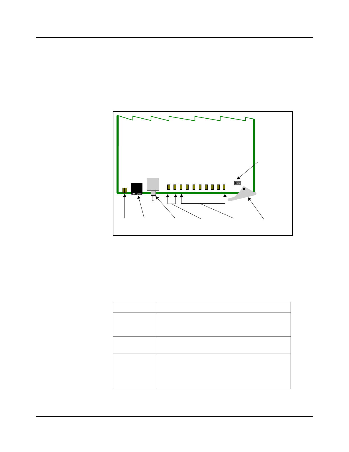
Front Module
Figure 1-1 is a generic top-front view of a typical 6800+ module and shows the
general location of standard LEDs, controls, and jumpers. The number of
control and monitoring LEDs on 6800+ modules varies.
Figure 1-1. Typical 6800+ Module
Table 1-3 on page 4 briefly describes generic 6800+ LEDs, switches, and
jumpers. See “Chapter 3: Operation” for more information on specific
HMX6803+ and OP+HMX+ module controls, LEDs, and jumpers.
Table 1-3. Generic 6800+ Module Features
Feature Description
Module status
LEDs
Mode select
rotary switch
Navigation
toggle switch
Various color and lighting combinations of these LEDs
indicate the module state. See
page 61 for more information.
This switch selects between various control and
feedback parameters.
This switch navigates up and down through the available
control parameters:
• Down: Moves down through the parameters
• Up: Moves up through the parameters
“Monitoring LEDs” on
4 HMX6803+ and OP+HMX+ Installation and Operation Manual
Copyright © 2009, Harris Corporation
Page 21

Chapter 1: Introduction
Table 1-3. Generic 6800+ Module Features(Continued)
Feature Description
Control LEDs Various lighting combinations of these control LEDs
(sometimes referred to as “Bank Select LEDs”) indicate
which bank is currently selected. See
Indicated by Control LEDs” on page 42 for more
information.
“Selected Bank as
Monitoring
LEDs
Local/remote
control jumper
Each 6800+ module has a number of LEDs assigned to
indicate varying states/functions. See
“Monitoring
LEDs” on page 61 for a description of these LEDs.
• Local: This jumper setting locks out external control
panels and allows card-edge control only; limits the
functionality of remote software applications to
monitoring
• Remote: This jumper setting allows remote or local
(card-edge) configuration, operation, and monitoring
of the HMX6803+ and OP+HMX+ (this is the
default setting)
HMX6803+ and OP+HMX+ Installation and Operation Manual 5
Copyright © 2009, Harris Corporation
Page 22
Chapter 1: Introduction
Note
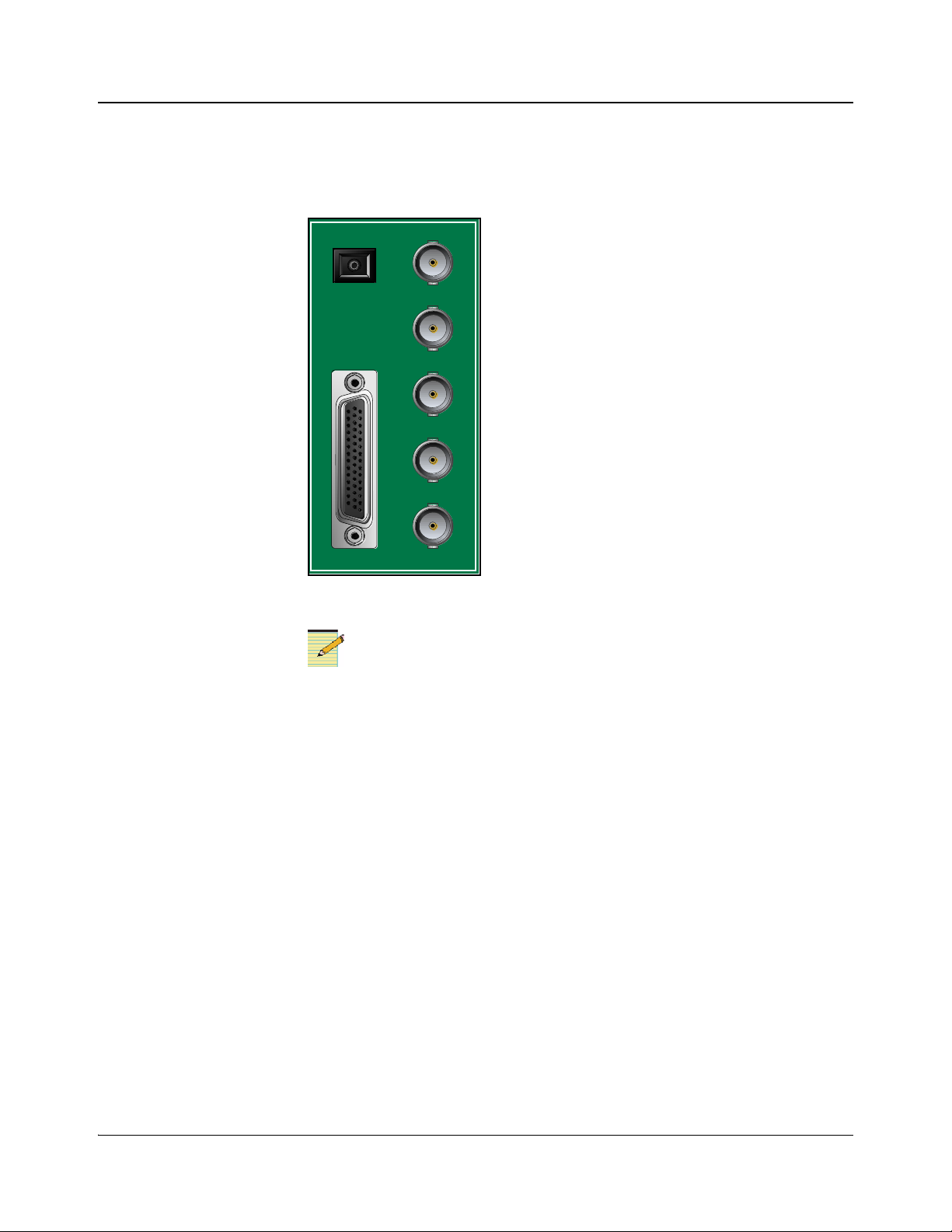
SDI I N 1
SDI OUT 1
SDI OUT 2
SDI OUT 3
SDI OUT 4
BREAKOUT
Fiber
Back Connectors
Figure 1-2 shows the double-slot back connector used by HMX6803+ and
OP+HMX+ modules.
Breakout Cables
Figure 1-2. HMX6803+ and OP+HMX+ Back Connector
To maintain optimal output video signal integrity, terminate unused output
video BNCs with 75Ω terminators.
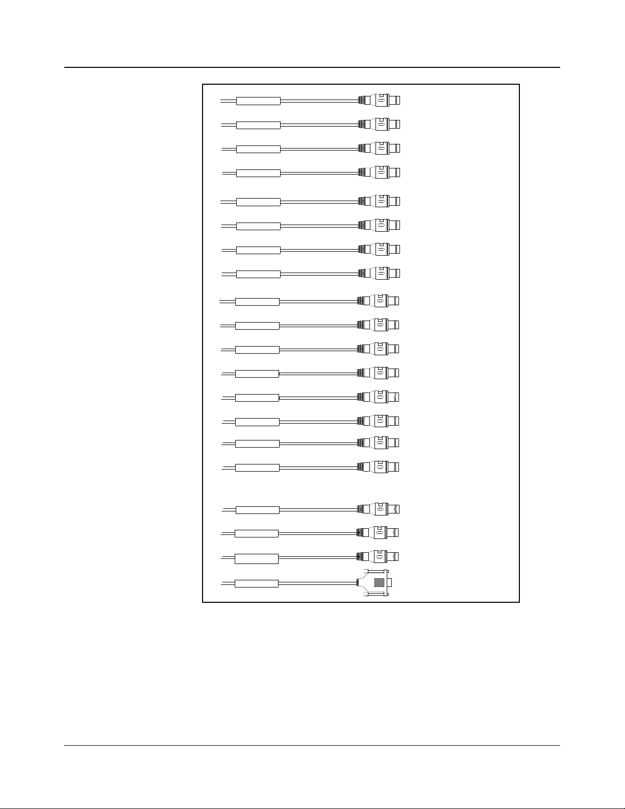
The standard HMX6803+ and OP+HMX+ ship with an unbalanced breakout
cable, pictured in
Figure 1-3. For information on ordering cables, see Table 2-1
on page 14.
If you need to make your own breakout cable, pinouts are listed in Table 1-4,
and pin numbers for the 44-pin connector are listed in Figure 1-4 on page 8.
6 HMX6803+ and OP+HMX+ Installation and Operation Manual
Copyright © 2009, Harris Corporation
Page 23
Chapter 1: Introduction
AES 1 In
AES 2 In
AES 3 In
AES 4 In
AES 5 In
AES 6 In
AES 7 In
AES 8 In
AES 1 Ou t
AES 2 Ou t
AES 3 Ou t
AES 4 Ou t
AES 5 Ou t
AES 6 Ou t
AES 7 Ou t
AES 8 Ou t
DARS In
Data I/O
Genlock
Serial
AES1 IN
AES2 IN
AES3 IN
AES4 IN
AES5 IN
AES6 IN
AES7 IN
AES8 IN
AES1 OUT
DARS IN
DATA I/O
GENLOCK
SERIAL
AES2 OUT
AES3 OUT
AES4 OUT
AES5 OUT
AES6 OUT
AES7 OUT
AES8 OUT
Figure 1-3. HMX6803+ and OP+HMX+ Breakout Cable
HMX6803+ and OP+HMX+ Installation and Operation Manual 7
Copyright © 2009, Harris Corporation
Page 24

Chapter 1: Introduction
Figure 1-4. Pin Numbers for 44-Pin Connector
Table 1-4. Pinouts for 44-Pin Connector
Pin No. on
DB-44M
1 BNC GENLOCK GENLOCK Black Black
2 BNC GND GENLOCK
3 BNC GND AES OUT 7
4 BNC AES IN 4 AES IN 4 White White
5 BNC GND AES IN 4 GND AES IN 4 White White
6 BNC AES IN 3 AES IN 3 White White
7 BNC GND AES IN 3 GND AES IN 3 White White
8 BNC DATA IO DATA IO Yellow Yellow
9 BNC GND DATA IO GND DATA IO Yellow Yellow
10 BNC AES OUT 2 AES OUT 2 Blue Blue
11 BNC GND AES OUT 2
12 BNC AES OUT 1 AES OUT 1 Blue Blue
13 BNC GND AES OUT 1
Connection Type Description Wire Label
GENLOCK Black Black
GND
AES OUT 7 Blue Blue
GND
AES OUT 2 Blue Blue
GND
AES OUT 1 Blue Blue
GND
External
Cable Color
BNC
Color
14 BNC GND AES IN 7 GND AES IN 7 White White
15 BNC AES IN 7 AES IN 7 White White
16
17
18 BNC AES OUT 7 AES OUT 7 Blue Blue
19 BNC DARS IN 1 DARS IN 1 Yellow Black
20 BNC GND DARS IN 1
GND
21 BNC AES IN 2 AES IN 2 White White
22 BNC GND AES OUT 3
GND
23 BNC AES OUT 3 AES OUT 3 Blue Blue
24 BNC GND AES OUT 6
GND
8 HMX6803+ and OP+HMX+ Installation and Operation Manual
Not Connected
DARS IN 1 Yellow Black
AES OUT 3 Blue Blue
AES OUT 6 Blue Blue
Copyright © 2009, Harris Corporation
Page 25

Table 1-4. Pinouts for 44-Pin Connector (Continued)
Chapter 1: Introduction
Pin No. on
DB-44M
25 162A10019X (DB9.5) RS232_GND
25 BNC GND AES OUT 4
26 BNC AES OUT 4 AES OUT 4 Blue Blue
27 BNC GND AES OUT 5
28 BNC AES IN 8 AES IN 8 White White
29 BNC GND AES IN 8 GND AES IN 8 White White
30 BNC GND AES IN 5 GND AES IN 5 White White
31 162A10019X (DB9.3) BALANCED
32 162A10019X (DB9.8) BALANCED
33 BNC GND AES OUT 8
Connection Type Description Wire Label
SERIAL Black N/A
(DB9)
AES OUT 4 Blue Blue
GND
AES OUT 5 Blue Blue
GND
SERIAL Red N/A
SERIAL IN(DB9)
SERIAL Yellow N/A
SERIAL IN+
(DB9)
AES OUT 8 Blue Blue
GND
External
Cable Color
BNC
Color
34 BNC AES OUT 8 AES OUT 8 Blue Blue
35 162A10019X (DB9.1) RS422_FR_GN
D (DB9)
35 BNC GND AES IN 2 GND AES IN 2 White White
36 BNC AES IN 1 AES IN 1 White White
37 162A10019X (DB9.9) RS422_FR_GN
D (DB9)
37 BNC GND AES IN 1 GND AES IN 1 White White
38 BNC AES OUT 6 AES OUT 6 Blue Blue
39 162A10019X (DB9.7) BALANCED
SERIAL OUT(DB9)
40 162A10019X (DB9.2) BALANCED
SERIAL OUT+
(DB9)
41 BNC AES OUT 5 AES OUT 5 Blue Blue
42 BNC GND AES IN 6 GND AES IN 6 White White
43 BNC AES IN 6 AES IN 6 White White
44 BNC AES IN 5 AES IN 5 White White
SERIAL Black N/A
SERIAL Black N/A
SERIAL Blue N/A
SERIAL Green N/A
HMX6803+ and OP+HMX+ Installation and Operation Manual 9
Copyright © 2009, Harris Corporation
Page 26
Chapter 1: Introduction
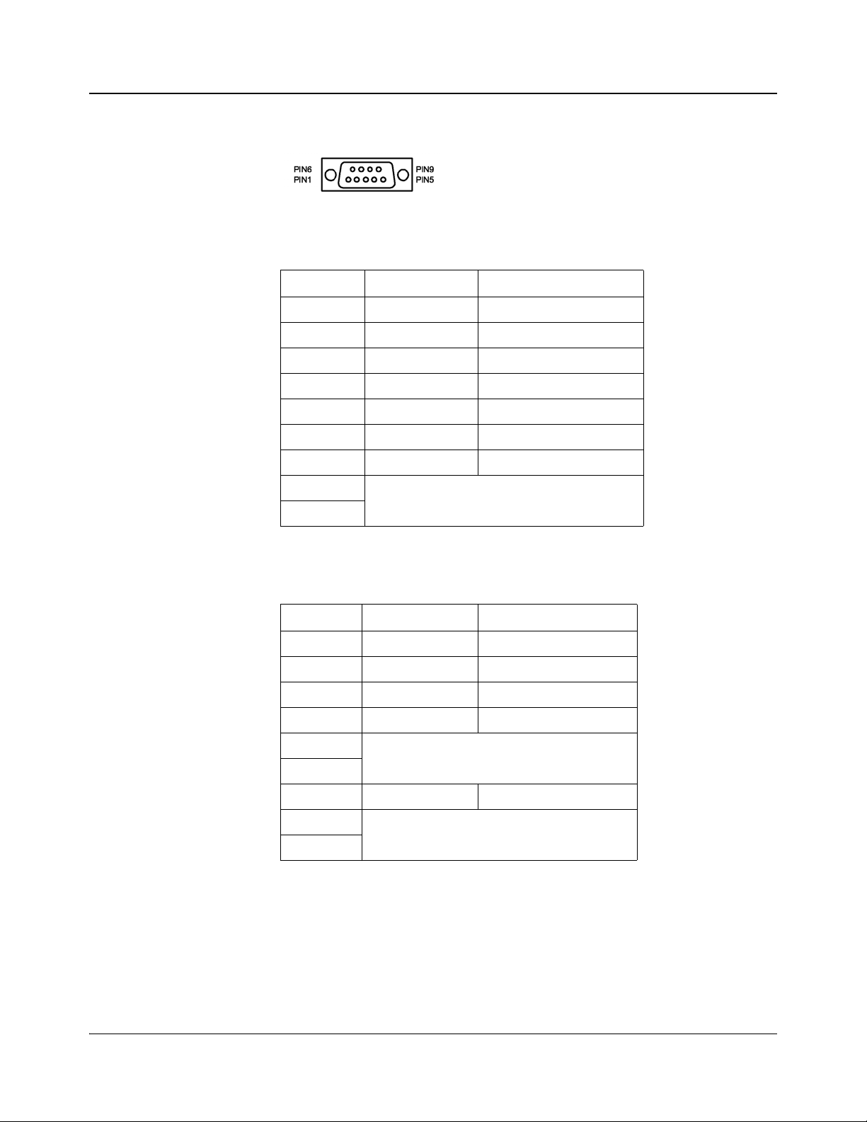
RS-422/232 Cable
Figure 1-5. Pin Numbers for RS-422/232 Female Connector
Table 1-5. Pin Assignment of DB-9 Connector (Female) in RS-422
Format
Pin No. Signal Comments
1 FG Frame Ground
9 FG Frame Ground
5 FG Frame Ground
2 TA (Tx-) Transmitted Data 7 TB (Tx+) Transmitted Data +
8 RA (Rx-) Received Data 3 RB (Rx+) Received Data +
4
6
Not connected
Table 1-6. Pin Assignment of DB-9 Connector (Female) in RS-232
Format
Pin No. Signal Comments
1 FG Frame Ground
9 FG Frame Ground
5 FG Frame Ground
2 Tx Transmitted Data
7
8
3 Rx Received Data
4
6
Not connected
Not connected
10 HMX6803+ and OP+HMX+ Installation and Operation Manual
Copyright © 2009, Harris Corporation
Page 27
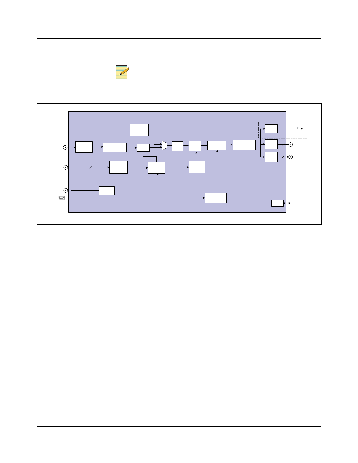
Signal Flow
Note
1
Available via breakout cable ( included).
3G/HD/SD-SDI
Metadata
Video
Delay
Test
pattern
generator
Video
proc
Audio
embed
Data
embed
Sample
rate
converter
Audio
delay
Metadata
router
CCS &QSEE
monitor ing
&
control
Laser
Driver
Audio
proc amp
OP+SFS+(C)xxD
Equalizer
AES In
8
3G/HD/SD-SDI
2
3G/HD/SD-SDI
2
Driver
Driver
CCS & SNMP
control
DARS DARS
AFD/WSS/VI
Detector
AFD/WSS/VI
Inserter
Chapter 1: Introduction
3G HD-SDI in and out are only available if your module has the optional
HMX68OPT
+3G license key.
Figure 1-6. HMX6803+ and OP+HMX+ Signal Flow Diagram
HMX6803+ and OP+HMX+ Installation and Operation Manual 11
Copyright © 2009, Harris Corporation
Page 28

Chapter 1: Introduction
12 HMX6803+ and OP+HMX+ Installation and Operation Manual
Copyright © 2009, Harris Corporation
Page 29

Unpacking the Module
Before you install modules, perform the following:
• Check the equipment for any visible damage that may have occurred during
transit.
• Confirm receipt of all items on the packing list. See “Checking the Packing
List” for more information.
Contact your Customer Service representative if parts are missing or
damaged.
• Remove the anti-static shipping pouch, if present, and all other packaging
material.
• Retain the original packaging materials for possible re-use.
See “Unpacking/Shipping Information” on page ix for information about
returning a product for servicing.
Chapter 2
Installation
HMX6803+ and OP+HMX+ Installation and Operation Manual 13
Copyright © 2009, Harris Corporation
Page 30

Chapter 2: Installation
Checking the Packing List
\
Table 2-1. Available Product Packages
Ordered Product Content Description
HMX6803+D
OP+HMX+D
6800+OPT+16CAPM One breakout cable with unbalanced audio
• One HMX6803+ front module
• One double-slot back connector
• One 6800+OPT+16CAPM breakout cable
with unbalanced audio connectors
• One HMX6803+ and OP+HMX+ Installation
and Operation Manual
•One OP+HMX+ front module
• One double-slot back connector
• One 6800+OPT+16CAPM breakout cable
with unbalanced audio connectors
• One HMX6803+ and OP+HMX+ Installation
and Operation Manual
connectors
Choosing HMX6803+ and OP+HMX+ Upgrade Options
Basic HMX6803+ and OP+HMX+ modules have one SD-SDI input and four
SD-SDI outputs with embedded audio. The following firmware upgrades are
available:
Table 2-2. Available License Key Upgrades
Ordered Product Content Description
HMX68OPT-AES8 Adds four discrete AES inputs, for a total of eight
HMX68OPT-3G Adds 3G HD-SDI functionality to an 1.5G
HD-SDI and SD-SDI module
To purchase additional licen se keys, contact your Sales representative. To
activate a license key, see
“Adding a License Key” on page 26.
14 HMX6803+ and OP+HMX+ Installation and Operation Manual
Copyright © 2009, Harris Corporation
Page 31

Selecting an External Balun
The following baluns from Neutrik® or equivalent are recommended for the
unbalanced to balanced AES conversion:
• NADITBNC-F: Female chassis XLR 110Ω input - female BNC 75Ω
output.
http://www.neutrik.com/fl/en/audio/210_309314683/NADITBNC-F_detail.
aspx
• NADITBNC-M: Female BNC 75Ω input - male chassis XLR 110Ω output.
http://www.neutrik.com/fl/en/audio/210_2044239418/NADITBNC-M_det
ail.aspx
• NADITBNC-FX: Female cable end XLR 110Ω input - female BNC 75Ω
output.
http://www.neutrik.com/fl/en/audio/210_1576769505/NADITBNC-FX_det
ail.aspx
• NADITBNC-MX: Female BNC 75Ω input - male cable end XLR 110Ω
output.
http://www.neutrik.com/fl/en/audio/210_1923043515/NADITBNC-MX_d
etail.aspx
Chapter 2: Installation
HMX6803+ and OP+HMX+ Installation and Operation Manual 15
Copyright © 2009, Harris Corporation
Page 32

Chapter 2: Installation
Note
Note
CJ1 jumper
Remote control
setting
Local control
setting
3 2 1 3 2 1
Setting Jumper CJ1 for Local or Remote Control
The HMX6803+ and OP+HMX+ module has one jumper, CJ1, which sets the
module for local or remote control.
You need to configure modules for local or remote operation prior to
power-up. To change the configuration, first remove power from the module,
reset the jumper, and then reapply power.
Figure 2-1. Jumper Location
1. Locate jumper CJ1 on the module (behind the mode select rotary switch).
Figure 2-1 shows the location of the CJ1 jumper.
2. Place a jumper on pins 1 and 2 to set the module for Remote control, or pins
2 and 3 to set the module for Local control. See Figure 2-2.
Figure 2-2. CJ1 Settings for Local and Remote Control
The white triangle near the jumper pins on the module
indicates pin 1.
16 HMX6803+ and OP+HMX+ Installation and Operation Manual
Copyright © 2009, Harris Corporation
Page 33

Maximum 6800+ Frame Power Ratings
Caution
Note
See the FR6802+ Frame Installation and Operation Manual for information
about installing and operating an FR6822+, FR6802+QXF or FR6802+ frame
and its components.
Before installing this product, read the 6800+ Series Safety
Instructions and Standards Manual shipped with every 6800+ Frame
Installation and Operation Manual or downloadable from our website.
This safety manual contains important information about the safe
installation and operation of 6800+ series products.
The power consumption for the HMX6803+ and OP+HMX+ modules is 12 W.
Table 2-3 describes the maximum allowable power ratings for 6800+ frames.
Note the given maximums before installing any 6800+ modules in your frame.
HMX6803+ and OP+HMX+ modules operate only in fan-cooled FR6802+ and
FR6822+ frames, subject to the limitations shown in
cannot be installed in 6800/7000 series frames.
Chapter 2: Installation
Table 2-3. These modules
To maintain proper temperatures, ensure that the front panel is closed at all
times and that the fan module is fully operational.
Table 2-3. Maximum Power Ratings for 6800+ Frames
Max. Frame
6800+ Frame Type
Power
Dissipation
FR6802+XF
(frame with AC power supply)
FR6802+XF48
(frame with DC power supply)
FR6802+QXF frame
(with AC or DC power supply)
FR6822+ frame (with AC or DC power supply) 120W 20 6 W
120 W 20 6 W
105 W 20 5.25 W
120W 20 6 W
Number of
Usable
Slots
Max. Power
Dissipation
Per Slot
HMX6803+ and OP+HMX+ Installation and Operation Manual 17
Copyright © 2009, Harris Corporation
Page 34

Chapter 2: Installation
Installing 6800+ Modules
Required Frames and Back Connector Types
HMX6803+ and OP+HMX+ modules have double-width back connectors that
can be installed in an FR6802+XF, FR6822+, or FR6802+QXF frame.
HMX6803+ and OP+HMX+ modules cannot be installed in an FR6802+DM
frame, a FR6800/7000 frame, or a frame without fans.
See your 6800+ Frame Installation and Operation Manual for details on
installing back connectors in an FR6802+ or FR6822+ frame.
A FR6802+RM (Rear Support Extension Rails for 6800+ series frames) option
is recommended for the HMX6803+ and OP+HMX+ modules. See your 6800+
Frame Installation and Operation Manual for installation instructions.
Installing and Removing HMX6803+ Modules
These modules require no specialized installation or removal procedures.
However, if installing both front and rear modules, ensure that the back module
is installed first before plugging in the front module.
When removing both the front and rear modules, ensure that the front module is
unplugged from the frame first, before removing the rear module.
• See the 6800+ Frame Installation and Operation Manual for information
about installing and operating a frame and its components.
• See the 6800+ Safety Instructions and Standards Manual for important
information about safely installing your module.
Once you have installed your HMX6803+ and OP+HMX+ modules, you can
connect them to the appropriate input and outputs.
Installing OP+HMX+ Modules
Front and back modules in the OPTO+ series have plastic caps that protect the
fragile laser connections from damage. You must remove these protective
covers before you install the back and front modules (see
18 HMX6803+ and OP+HMX+ Installation and Operation Manual
Figure 2-3).
Copyright © 2009, Harris Corporation
Page 35

Chapter 2: Installation
Caution
Caution
Remove these
protective covers
Remove this
protective cover
In addition, all fiber optic connections must be inspected and cleaned before
they are assembled. Carefully follow the inspection and cleaning steps
described in the next pages. Additional safety information appears in
“Laser
Safety Guidelines” on page 79.
Ensure that you remove the fiber optic protective covers from the front and
back modules before installation. Take care to avoid touching the fiber optic
connections. Thoroughly clean the connections before installa tion. Remove
power from the frame before installing or removing back modules.
Back Module Installation
Figure 2-3. Protective Covers for Laser Connectors
Follow these steps to install the back module into an FR6802+XF,
FR6802+XF48, FR6822+, or FR6802+QXF frame:
1. Remove a blank back plate from the frame.
Do not discard the blank back plates. They may be needed for future
configurations.
2. On the side of the back module that inserts into the front module, remove
the inner protective cap from the fiber connection (see Figure 2-3 on
page 19).
Microscopic dust or other contaminants can seriously impair or disable a
fiber optic network. Observe strict cleaning procedures. Do not touch the
end of the fiber.
3. Follow the inspection and cleaning procedure that begins on page 21.
HMX6803+ and OP+HMX+ Installation and Operation Manual 19
Copyright © 2009, Harris Corporation
Page 36

Chapter 2: Installation
Caution
Note
Front Module Installation
4. If it is already installed, remove the front module from the slot.
5. Install the new back module by inserting the bottom lip into the required
frame slot, and then screwing it into place.
Ensure that the EMI gaskets on the right side of the back module remains in
place during the installation. The EMI gaskets fit tightly.
6. Apply the adhesive label to the back module if it is supplied separately.
Follow these steps to install the front module:
1. Pull out the finger-release screws on the right and left side of the front panel
of the frame, and then open it.
2. Locate the front module slot that corresponds with the matching back
module.
3. Gently remove the outer and inner protective caps from the laser
connections. (see Figure 2-3 on page 19).
Microscopic dust or other contaminants can seriously impair or disable a
fiber optic network. Observe strict cleaning procedures. Do not touch the
end of the fiber.
4. Follow the fiber cleaning instructions that begin on page 21.
5. Ensure that your front module matches with a corresponding back module
6. Slide the module into the guides in the frame.
7. When the module edge is flush with the guide, close the extractor handle.
8. Close the front panel to ensure proper frame ventilation.
Removing OP+HMX+ Modules
Front Module
Follow these steps to remove a front module from a frame:
1. Pull out the finger-release screws on the right and left side of the front panel
of the same name.
The module is properly seated when its edge is flush with the guide edge
and the extractor handle closes.
To prevent overheating, keep the front panel closed and all back module
plate slots covered during operation.
The removal steps provided here are simila r to those outlined in your 6800+
Frame Installation and Operation Manual. Refer to that manual for detailed
information about installing and operating a frame and its components.
of the frame, and then open the front panel.
20 HMX6803+ and OP+HMX+ Installation and Operation Manual
Copyright © 2009, Harris Corporation
Page 37

2. Grasp the extractor handle on the installed module, and then pull the
module out of its slot. Use the handle as a lever.
3. Close the front panel to ensure proper frame ventilation.
Back Module
Follow these steps to remove a back module from a frame:
1. Remove the front module, as described above.
2. Unscrew the top of the corresponding back module, and then tip it towards
you.
3. Pull the bottom lip of the back module from its slot.
4. Reinstall a new or blank back plate in the empty slot to ensure proper frame
ventilation.
5. Reinstall the front module.
Inspecting and Cleaning Fiber Optic Connections
Small amounts of microscopic dust or other contaminants can seriously impair
or disable a fiber optic network. To ensure that your network operates reliably,
you must carefully inspect and clean each connection when installing OPTO+
products.
Table 2-4 lists some typical contaminants of a fiber optic connection. The
inspection and cleaning procedure begins on page 22.
Chapter 2: Installation
Important Points
Table 2-4. Typical Contaminants
Contaminant Comments
Dust particle, 1 micron Can block up to 1% of th e light transmission,
creating a loss of 0.05 dB
Dust particle, 9 microns Although microscopic, the particle can completely
block the fiber core
Human hair Typically 50 to 75 microns in diameter
Oil Frequently caused by touching
Film residues Can accumulate from vapors or smoke
Powdery coatings Can be left behind after water or other solvents
evaporate
• Before you begin cleaning, always inspect the fiber connections.
• Inspect and clean both fiber ends every time you make a connection.
• Keep a protective cap on unplugged fiber connectors .
• Do not touch the end of a fiber.
• Store unused protective caps in a clean resealable container, located nearby
for easy access.
HMX6803+ and OP+HMX+ Installation and Operation Manual 21
Copyright © 2009, Harris Corporation
Page 38

Chapter 2: Installation
Warning
Zone 2
(20 t o 50 micr on d iam et er)
Maximum of 3 scratches <1.0 mi cron width is acceptable;
Maximum 1.0 micron light dig is acceptable
Zone 1
(0 to 20 micron diam eter)
No scratches or digs are allowed
Zone 3
(50 to 126 micron diameter)
Maximum 25 micron dig is acceptable;
Maximum scrat ch size of 1.0 micron is acceptable
Maximum 25 micron diameter dig is acceptable
Scratches and dust
• Do not reuse cleaning tissues or swabs.
• Do not allow alcohol or another wet cleaning agent to dry on a fiber end.
• Never touch the dispenser tip of an alcohol bottle or any clean portion of a
tissue or swab.
• Use care when handling the fiber; do not twist or pull.
• Keep your cleaning fluids away from open flame or spark.
Figure 2-4 describes the acceptable limits of defects in a fiber connection.
Figure 2-4. Fiber Optic Cross Section
Inspection and Cleaning Procedure
22 HMX6803+ and OP+HMX+ Installation and Operation Manual
Inspection
Eye damage may occur if an optical instrument such as a microscope,
magnifying glass, or eye loupe is used to stare at an energized fiber end.
To inspect and clean the fibers, follow these steps:
1. Ensure the fiber is not “live.”
2. Inspect the fiber endface with a fiberscope.
3. If the fiber endface is clean, return to the installation instructions on page 19
for back modules or page 20 for front modules.
If the connector is dirty, proceed to the dry cleaning instructions below.
Copyright © 2009, Harris Corporation
Page 39

Chapter 2: Installation
Caution
Caution
Dry Cleaning
If you are using cartridge or pocket-style dry cleaning tools, follow the
manufacturer’s directions. If you are using lint-free wipes, follow these steps:
1. Fold the lint-free wipe four to eight times into a square, taking care to avoid
touching the cleaning surface of the wipe.
2. Lightly wipe the fiber tip in the central portion of the lint-free wipe.
Do not scrub the fiber. Excessive rubbing will leave scratches.
3. Repeat the wiping action on another clean section of the wipe or a new
wipe.
4. Inspect the connector again with the fiberscope.
5. If the connection is clean, return to the installation steps on page 19 for back
modules, or page 20 for front modules.
If the connector is still dirty, proceed to the wet cleaning instructions.
Wet Cleaning
Using 99% isopropyl alcohol and lint-free wipes, follow these steps to wet clean
the fiber:
1. Fold the wipe into a square, about four to eight layers thick.
2. Moisten one section of the lint-free wipe with one drop of 99% alcohol,
ensuring that a portion of the wipe remains dry.
3. Lightly wipe the fiber end in the alcohol-moistened portion of the lint-free
wipe.
4. Immediately repeat the wiping action on the dry section of the wipe,
removing any residual alcohol.
5. Inspect the fiber endface again, and if necessary, repeat the wet cleaning
with another clean section of the lint-free wipe.
Do not scrub the fiber. Excessive rubbing will leave scratches.
6. Dry clean any remaining residue, and then inspect the connector again.
7. If the contamination persists, repeat the dry and wet cleaning procedure
until the endface is clean.
If the fiber end still remains dirty after repeated cleaning attempts, call
Customer Service for further instructions.
If the fiber end is clean, return to the installation instructions on page 19 for
back modules, or page 20 for front modules.
HMX6803+ and OP+HMX+ Installation and Operation Manual 23
Copyright © 2009, Harris Corporation
Page 40

Chapter 2: Installation
Upgrading Module Firmware
This module’s firmware can be updated using CCS Pilot, CoPilot, or Navigator
version 3.1.1 or higher, or the HTTP software upgrade tool. In order to perform
these upgrades, your frame must be equipped with a 6800+ETH module. See
your frame manual for more information.
24 HMX6803+ and OP+HMX+ Installation and Operation Manual
Copyright © 2009, Harris Corporation
Page 41

Operating Notes
Note
When you set the control parameters on the HMX6803+ and OP+HMX+,
observe the following:
• If you make changes to certain parameters, other related parameters may
also be affected. See “Cross-Functional Parameter Changes” on page 38 for
more information.
• When you change a parameter, the effect is immediate. However, the
module requires up to 30 seconds to save the latest change. After 30
seconds, the new settings are saved and will be restored if the module loses
power and must be restarted.
Q-SEE Compliant Thumbnails
When installed in an FR6802+QXF or FR6822+ frame that also contains a
6800+ETH resource module, HMX6803+ and OP+HMX+ module control
windows have an extra Streaming tab in CCS Pilot and Navigator (version
3.2.1 or later). There you can view output video from the module.
In addition, video from the HMX6803+ and OP+HMX+, displayed at up to
three frames per second, can be displayed on the 6800+ETH’s control page, and
(for CCS Navigator only) on Graphical Navigation pages.
Chapter 3
Operation
HMX6803+ and OP+HMX+ modules all show a HMX6803+ label in
Navigator.
Thumbnail streaming is not supported for the following video standards:
• 1080i 60
• 720p 60
• 1080p 24/25/29.97/30
• 1080psF 23.98/24
• 1080p 50/59.94/60
HMX6803+ and OP+HMX+ Installation and Operation Manual 25
Copyright © 2009, Harris Corporation
Page 42

Chapter 3: Operation
Note
Activating HMX6803+ and OP+HMX+ Functions
The following sections provide information about the HMX6803+ and
OP+HMX+ special functions:
• “Adding a License Key” on page 26
• “Audio Test Tones” on page 27
• “Audio Embedding Modes” on page 27
• “Audio Embedding Errors” on page 31
• “Input Audio Rate” on page 33
• “Audio Path” on page 34
• “Seamless Sound Function” on page 34
• “Test Pattern Generator” on page 36
• “Dolby-E Automatic Header Alignment” on page 36
• “Audio Delay Ranges” on page 36
• “Maintaining Audio/Video Alignment” on page 36
Adding a License Key
For assistance with a license key, or to purchase a license key, please
contact your Sales representative.
To enter a license key to activate AES audio and/or 3G HD video, your CCS
software must be in Control mode.
1. Select the HMX6803+ module in the Navigation pane, right click, and then
select Control to open the module’s Control window.
2. Select the Parameters tab.
3. Select General in the tree view, and then type your license key in the
License Key field.
HMX6803+ and OP+HMX+ modules appear as HMX6803+ modules in
Navigator.
If your license key is valid, the Installed Options field displays the features
that are activated on the module, which in this case is 3G and/or AES.
26 HMX6803+ and OP+HMX+ Installation and Operation Manual
Copyright © 2009, Harris Corporation
Page 43

Audio Test Tones
Table 3-1 describes the frequency and levels of each audio output test tone,
available as a selection from each of the Output Ch (1–16) Source Select and
Audio Procamp AES (1A-8B) Out Source parameters (see
Table 3-1. Audio Test Tones
Test Tone Frequency Level
Test Tone 1 400 Hz -18 dBFS
Test Tone 2 1 kHz -18 dBFS
Test Tone 3 2 kHz -18 dBFS
Test Tone 4 4 kHz -18 dBFS
EBU R68 1 kHz -18.06 dBFS
SMPTE RP155 1 kHz -20 dBFS
Audio Embedding Modes
The audio embedder component in the HMX6803+ and OP+HMX+ is
composed of several smaller subcomponent blocks:
Chapter 3: Operation
page 57).
• One ancillary data stripper (ADS)
• Four audio embedding subcomponents
The first subcomponent is an ancillary data stripper ( ADS). This block removes
all ancillary data packets in the input SDI stream, prior to embedding.
Following the ADS block are four separate audio-embedding subcomponents.
Each subcomponent has the ability to operate on only one audio group, either
appending or overwriting a predetermined group onto the SDI stream.
The audio embedding modes are Audio Group (1–4) Embedding Mode
parameters (see
page 51). Table 3-2 briefly describes the Off, Append,
OverWrt, and Auto options available from each of the embedding modes.
Table 3-2. Embedding Mode Options
Options Description
Off Deactivates embedding of the selected audio group
Append Attempts to insert the audio dat a and co ntrol packets
immediately following the last existing audio data/control
packet in the horizontal ancillary region (see
Embedding” on page 28)
OverWrt Attempts to overwrite existing audio data and control
packets of the same group number with the new audio data
(see
“Overwrite Embedding” on page 30)
“Append
HMX6803+ and OP+HMX+ Installation and Operation Manual 27
Copyright © 2009, Harris Corporation
Page 44

Chapter 3: Operation
EAV
ADS before em bedding
EAV
ADS afte r e m bedding group 1
Group 1
ADS before em bedding
Other
auxilliary dat a
A
EAV
Other
auxilliary dat a
B
ADS afte r e m bedding group 1
Group 1
EAV
Other
auxilliary dat a
A
Other
auxilliary dat a
B
Append Embedding
Table 3-2. Embedding Mode Options (Continued)
Options Description
Auto Attempts first to overwrite existing audio data and control
packets of the same audio group number; failing that, it
appends the new audio data and control packets
immediately following the last existing audio data/control
packet (refer to the Audio Group (1–4) Exists parameters
on
page 51 to determine what audio groups are already
present in the incoming SDI signal)
When you select Append embedding, the HMX6803+ and OP +HMX+
attempts to insert the audio data and control packets immediately following the
last existing data/control packet in the horizontal ancillary data space (ADS).
Append embedding is only valid if the audio group to be embe dded does not
already exist.
Figure 3-1 shows how append embedding will appear in the ancillary data space
when there is no previous audio or other data.
Figure 3-1. In Append Embedding Mode, Adding Group 1 When No Other Data is Present
Figure 3-2. In Append Embedding Mode, Adding Group 1 When Auxiliary Data is Present
28 HMX6803+ and OP+HMX+ Installation and Operation Manual
When auxiliary data exists in the ancillary data space, appended audio appears
following that data, as shown in
Figure 3-2.
Copyright © 2009, Harris Corporation
Page 45

Chapter 3: Operation
ADS afte r attem pt ing to em bed gr oup 1
ADS before em bedding
Pre-existing
Group 1
EAV
EAV
Pre-existing
Group 1
R esu l t : Error i s returne d
ADS afte r em be ddi ng group 2
EAV Group 1
Group 2
EAV
ADS before e m bedding
Group 1
ADS before em be ddi ng
EAV
Group 2
ADS aft er embedding gr oup 1
Group 1
EAV
Group 2
If you attempt to insert audio into Group 1 when Group 1 audio data already
exists in the ancillary data space, an error will be returned, as shown in
Figure 3-3.
Figure 3-3. Append Embedding Mode When Adding Group 1 and a Group 1 Already Exists
If you insert Group 2 audio when there is pre-existing Group 1 audio in the
ancillary data space and no Group 2 audio, the Group 2 audio will be inserted
following the Group 1 audio, as shown in
Figure 3-4.
Figure 3-4. Append Embedding Mode, Adding Group 2 Following Group 1
If you insert Group 1 audio when there is pre-existing Group 2 audio in the
ancillary data space and no Group 1 audio, the Group 1 audio will be inserted
following the Group 2 audio, as shown in
Figure 3-5. Append Embedding Mode, Adding Group 2 Following Group 1
HMX6803+ and OP+HMX+ Installation and Operation Manual 29
Copyright © 2009, Harris Corporation
Figure 3-5.
Page 46

Chapter 3: Operation
Note
ADS before em be ddi ng
EAV
Other
auxillary
data
Other
auxillar y
data
Other
auxillar y
data
ADS after att em pting t o em be d gr oup 1
EAV
R esu l t : Error i s re t u rned
Other
auxillary
data
Other
auxillar y
data
Other
auxillar y
data
ADS before e m bedding
EAV
EAV
ADS after attempting to embed group 1
R esu l t : Error i s re t u rned
An audio group cannot be divided. In Append embeddin g, the audio group is
always added following the last block in the ADS. If there is not enough room
to append the audio group following the last block of auxiliary data or audio in
the ADS, the attempt will result in an error, as shown in
Figure 3-6.
Figure 3-6. Append Embedding Mode Returns Error When Auxiliary Data Exists in all Audio Groups
Overwrite Embedding
When you select Overwrite embedding, the module attempts to overwrite any
existing audio data and control packets of the same group number with the new
audio data. This setting is valid only if the audio group to be embedded already
exists. If the new sample distribution does not exactly match the existing audio
data packet sample distribution, the embedder will mark some audio data
packets for deletion (DID word will be set to 180h).
Figure 3-7. Overwrite Embedding Mode When There is No Pre-Existing Audio
To avoid sample distribution issues, activate the ADS Clean feature (see
“ADS Clean Parameter” on page 39).
When you attempt Overwrite embedding and there is no previous audio (as in
Figure 3-7), it will return an error because there is nothing to overwrite.
30 HMX6803+ and OP+HMX+ Installation and Operation Manual
Copyright © 2009, Harris Corporation
Page 47

Figure 3-8 shows how overwrite embedding will appear in the ancillary data
EAV
ADS before e m bedding
other
auxilliary data
A
other
auxilliary data
B
ADS after attempting to embed group 1
EAV
other
auxilliary data
A
other
auxilliary data
B
R esu l t : Error i s re t urn ed
ADS after embeddi ng gr oup 1
( with overw ri t e group spec i f i ed as G roup 1 )
G roup 1
EAV
ADS before em be ddi ng
Pre-existing Group 1
EAV
space when there is auxiliary data where Group 1 should be inserted.
Figure 3-8. Overwrite Embedding Mode When There is Auxiliary Data on Group 1
Figure 3-9 shows how overwrite embedding will appear in the ancillary data
space when there is pre-existing Group 1 audio. This operation is successful.
Chapter 3: Operation
Figure 3-9. Overwrite Embedding Mode When There is Group 1 Audio in the Group 1 Space
Audio Embedding Errors
Table 3-3 describes Group (1–4) Append Embedding Error and Group (1–4)
Overwrite Embed Error audio embedding errors (also see page 51).
Table 3-3. Audio Embedding Error Descriptions
Error Description
Group (1–4)
Append
Embedding
Error
Group (1–4)
Overwrite
Embed Error
HMX6803+ and OP+HMX+ Installation and Operation Manual 31
Copyright © 2009, Harris Corporation
To avoid embedding errors, follow these guidelines:
This error occurs if the embedder is set to Append mode
for a particular audio group, but that audio group already
exists in the incoming SDI signal.
In this case, the embedder does not embed another audio
data and control packet of the same audio group, as this
will result in incorrect audio sample distribution.
This error occurs if the embedder is set to Overwrite
mode for a particular audio group, but that audio group
does not exist in the incoming SDI signal
Page 48

Chapter 3: Operation
• Set the embedding mode to Auto. If the group is present, it will be
overwritten; if it is not present, it will be appended. The overwrite and
append errors are actually warnings that the operation is not being
performed.
• In SD-SDI mode do not overwrite embedded groups of 20-bit audio
samples with groups of 24-bit audio samples. The required extended data
packet information appended to that group may over write a pre-existing
audio group. For 24-bit audio embedding, use the ADS Clean feature
provided.
Mono Channel Audio Embedding
To embed audio on a channel-by-channel (mono) basis, preserving some
embedded audio channels while replacing others from external AES sources,
follow these steps:
1. Configure the input audio routing path (Input > Audio > Routing) by
selecting audio pair sources to the individual audio sample rate converters.
By default, SRCs 1-8 are assigned to the 8 deembedded audio sources
(DMX Grp1 Ch1/2, DMX Grp1 Ch3/4, DMX Grp2 Ch1/2, etc.) and SRCs
9-16 are assigned to the external AES audio sources (AES1a/1b, AES2a/2b,
etc.).
2. Configure the output audio routing path (Output > Audio Source Select >
Embedded Audio) by selecting sources to each mono embedded audio
output channel.
Each SRC (SRC1a, SRC1b, SRC2a, etc.) can be selected to any output
embedded audio channel, allowing for any input-to-output au dio
configuration.
3. Remove or preserve existing embedded audio with the ADS Clean
parameter (Processing > Audio).
4. Use the Audio Group (1-4) Embedding Mode parameters (Processing >
Audio > Embedding) to select the desired audio group embedding mode for
each audio group.
•In Auto mode, non-existing audio groups are appended and existing
audio groups are overwritten.
•In Overwrite mode, the original audio is preserved using the settings in
step 2.
•In Off mode, audio groups are untouched unless the ADS Clean
parameter is enabled.
Example: Replacing Audio Channel 1 in Group 1 Only
To replace only embedded audio channel 1 in group 1 with audio from external
AES 1A source, follow these steps:
1. Leave the input audio routing path at the default configuration (SRCs 1-8
from deembedded audio, SRCs 9-16 from external AES audio).
32 HMX6803+ and OP+HMX+ Installation and Operation Manual
Copyright © 2009, Harris Corporation
Page 49

Chapter 3: Operation
Note
2. Route the output audio sources as follows (Output > Audio Source Select >
Embedded Audio):
Output Emb Ch 1 Source Select: SRC9a
Output Emb Ch 2 Source Select: SRC1b
Output Emb Ch 3 Source Select: SRC2a
Output Emb Ch 4 Source Select: SRC2b
3. Preserve existing embedded audio by setting the ADS Clean parameter
(Processing > Audio) to No.
4. Set the audio group embedding mode (Processing > Audio > Embedding):
Audio Group 1 Embedding Mode: Auto
Audio Group 2 Embedding Mode: Off
(incoming audio group 2 will be preserved)
Audio Group 3 Embedding Mode: Off
(incoming audio group 3 will be preserved)
Audio Group 4 Embedding Mode: Off
(incoming audio group 4 will be preserved)
Audio V-Fade
Input Audio Rate
To enable a smooth deembedded audio V-fade transition when switching video
sources, set the
Audio V-Fade parameter to Enable, and the Audio LOV Output
Mode parameter to Mute.
AES outputs in this mode are not AES11 alignment compliant and are not
aligned with video.
For proper operation in this mode, set the user delay parameters for all
audio channels (Processing > Audio > Delay) to the same value.
When embedding audio in PCM mode (Audio Ch [1–16] Format = PCM or
Audio Ch [1–16] Format
=
PCM), the input audio sample rate may be from 32 kHz to 108 kHz. This
= Auto and Audio Ch [1–16] Format Feedback
input audio will be sample rate converted to 48 kHz prior to embedding in the
video signal; as well, the embedder will indicate 48 kHz in the “Rate” word of
the audio control packet for each embedded audio group.
When embedding audio in Non-PCM mode (Audio Ch [1–16]
Format
[1–16] Format Feedback
= Non-PCM or Audio Ch [1–16] Format = Auto and Audio Ch
= Non-PCM), the input audio sample rate must be
48 kHz, and it must be frequency locked to the source video. In this scenario,
the sample rate conversion function is bypassed and the embedder will indicate
48 kHz in the “Rate” word of the audio control packet for each embedded audio
group.
(The parameters are listed on page 45.)
HMX6803+ and OP+HMX+ Installation and Operation Manual 33
Copyright © 2009, Harris Corporation
Page 50

Chapter 3: Operation
Note
Audio Path
The output audio source selection consists of two sets of controls.
• Input Sample Rate Conversion (SRC) routing source selections
Each SRC source can be assigned to one of the following sources:
• AES In (1A/1B to 8A/8B) (with AES8 option)
• Demuxed audio (Group 1 channels 1/2 to Group 4 channels 3/4)
• Output Audio Source Selection for the embedded audio
Each output embedded Audio channel can be assigned to one of the
following sources:
• SRC (1a to 16b)
• In Pair (SRC1a+1b to SRC16a+16b) Sum
• TstTone 400 Hz
• TstTone 1 kHz
• TstTone 2 kHz
• TstTone 4 kHz
• EBU R68
• SMPTE RP155
• SRC1a+2a
• SRC1b+2b
• SRC2b+3b
• SRC2a+4a
• SRC2b+4b
(The parameters are listed on page 45.)
Seamless Sound Function
When used in conjunction with HDX6803+ or SFS6803+ in a de-embedding
mode, the HMX6803+ can provide an uninterrupted (“popless”) embedding and
de-embedding path for the discrete audio channels regardless of the presence or
input switching of the video, as long as a constant video standard is maintained.
HMX6803+/OP+HMX+ connected to HDX6803+/OP+HDX+
HMX6803+/OP+HMX+ parameter settings (embedding module):
Set the Seamless Sound Enable parameter (Processing > Audio) to Enable.
Set the Audio LOV Output Mode to Pass.
If an audio group already exists and you want to replace it, set the ADS Clean
parameter to Yes (Processing > Audio > Embedding).
The ADS Clean parameter removes all audio groups from the vid eo stream.
34 HMX6803+ and OP+HMX+ Installation and Operation Manual
Copyright © 2009, Harris Corporation
Page 51

Chapter 3: Operation
Note
If the audio group already exists and you do not want to replace it, or if the
audio group to be embedded does not exist, set the ADS Clean parameter to No
(Processing > Audio > Embedding).
To set an audio group to be embedded to the Append mode, set the Audio
Group 1-4 Embedding Mode parameter to Append (Processing > Audio >
Embedding).
For optional minimum propagation delay, set the Video Delay Bypass
parameter to Yes (Processing > Video > Delay).
HDX6803+/OP+HDX+ parameter settings (de-embedding module):
Set the Seamless Sound Enable parameter (Processing > Audio) to Enable.
Set the Audio LOV Output Mode to Pass.
To set the AES output(s) to be sourced directly fro m the audio deembedder by
using the appropriate Demux Ch source, set the Output AES 1-8 Source Select
parameter to Demux Ch 1/2, Demux Ch 3/4, etc. (Output > Audio Source
Select > AES Audio).
For optional minimum propagation delay, set the Video Delay Bypass
parameter to Yes (Processing > Video > Delay).
HMX6803+/OP+HMX+ connected to SFS6803+/OP+SFS+
HMX6803+/OP+HMX+ parameter settings (embedding module):
Set the Seamless Sound Enable parameter (Processing > Audio) to Enable.
Set the Audio LOV Output Mode to Pass.
If an audio group already exists and you want to replace it, set the ADS Clean
parameter to Yes (Processing > Audio > Embedding).
The ADS Clean parameter removes all audio groups from the vid eo stream.
If an audio group already exists and you do not want to replace it, or if the audio
group to be embedded does not exist, set the ADS Clean parameter to No
(Processing > Audio > Embedding).
To embed an audio group in Append mode, set the Audio Group 1-4
Embedding Mode para meter to Append (Processing > Audio > Embedding).
For optional minimum propagation delay, set the Video Delay Bypass
parameter to Yes (Processing > Video > Delay).
SFS6803+/OP+SFS+ parameter settings (de-embedding module):
Set the Seamless Sound Enable parameter (Processing > Audio) to Enable.
Set the Audio LOV Output Mode to Pass.
To set the AES output(s) to be sourced directly fro m the audio deembedder
using the appropriate Demux Ch source, set the Output AES 1-8 Source Select
parameter(s) to Demux Ch 1/2, Demux Ch 3/4, etc. (Output > Audio Source
Select > AES Audio).
HMX6803+ and OP+HMX+ Installation and Operation Manual 35
Copyright © 2009, Harris Corporation
Page 52

Chapter 3: Operation
For optional minimum propagation delay, set the Frame Sync Bypass
parameter to Yes (Processing > Video > Synchronization).
Test Pattern Generator
When the Test Pattern Enable parameter (listed on page 54) is set to On, the
video output displays one of three options:
• 75% color bars
• Pathological
• 100% color bars
Dolby-E Automatic Header Alignment
When you embed Dolby E audio, the module automatically adjusts input audio
delay such that the Dolby E header resides on the line specified by the Dolby E
Start Line parameter, with a tolerance of ±1 line.
and default values for the Dolby E Start Line parameter.
Table 3-4. Dolby E Automatic Header Alignment by Video Standard
Video Standard Range Default
Table 3-4 shows the ranges
525 13–25 15
625 9–30 11
1080i/p/psF 15–54 19
720p 20–71 25
Audio Delay Ranges
Depending on the amount of delay applied to the video stream, the available
range for the audio delay parameters varies. The ranges are listed in
Table 3-5. Audio Delay Range Depending on the Amount of Video Delay
Condition Parameters Range
Video Delay greater than 31
frames
Video Delay less than 32
frames
Input Audio Ch 1–16 Delay
Input Audio AES 1A–4B Delay
Input Audio Ch 1–16 Delay
Input Audio AES 1A–4B Delay
0 to 660.00 ms
0 to 1320.00 ms
For Dolby-E automatic header alignment to operate correctly, the input SDI
must be frequency locked to the same reference source as the Dolby-E source.
Maintaining Audio/Video Alignment
Table 3-5.
When you use Sample Rate Conversion with PCM Audi o to chang e audio rates
and provide audio synchronization with output video, this introduces a delay in
the audio signal path.
36 HMX6803+ and OP+HMX+ Installation and Operation Manual
Copyright © 2009, Harris Corporation
Page 53

To maintain an alignment between video and audio in PCM mode, set the
Audio/Video Align parameter (Processing > Video > Delay) to Yes. This
introduces a matching video delay and maintains audio/video alignment.
When using Non-PCM Audio, or when sample rate converters are bypassed, set
the Audio/Video Align parameter (Processing > Video > Delay) to No to avoid
excessive video delay.
AFD/WSS/VI Detection and Insertion
AFD, WSS (625 only), and VI (526/625 only) embedded video metadata
specify the active area to be displayed from a video input. These codes do not
do any aspect ratio conversion themselves, but indicate how the vi deo should
appear to systems capable of interpreting the data.
• Seven input parameters (Input > AFD/VI/WSS De-embedder) on
HMX6803+ modules indicate the presence of AFD, WSS, and VI data
when you determine the lines where this data is likely to appear, if present.
• The single processing parameter (Out Aspect Ratio, which appears at
Processing > Video > AFD/VI/WSS) determines the options for the AFD
Select and VI Select parameters.
• Twelve output parameters (Output > AFD/VI/WSS Embedder) determine
the line to embed AFD, WWS, and/or VI codes on, the code(s) to be
embedded, and what happens when a code disappears from the input.
Chapter 3: Operation
HMX6803+ and OP+HMX+ Installation and Operation Manual 37
Copyright © 2009, Harris Corporation
Page 54

Chapter 3: Operation
Cross-Functional Parameter Changes
When you configure certain parameters, you force a change in other associated
parameters. The various conditions that affect parameter availability or settings
are described in the following sections:
• “Out Aspect Ratio” on page 38
• “ADS Clean Parameter” on page 39
• “PCM/Non-PCM Settings” on page 39
• “Channel Word Length” on page 40
• “Parameter Availability Based on Operating Mode” on page 40
Out Aspect Ratio
When the Out Aspect Ratio parameter (Processing > V ideo > AFD/VI/WSS) is
set to 4:3, the AFD Select and VI Select parameters (Output > AFD/VI/WSS
Embedder) have the following options:
•16:9 top
•14:9 top
•>16:9 in 4:3
• 4:3 full
•16:9 l
•14:9 l
• 4:3 a 14:9
• 16:9 l a 14:9
• 16:9 l a 4:3
When the Out Aspect Ratio parameter (Processing > V ideo > AFD/VI/WSS) is
set to 16:9, the AFD Select and VI Select parameters (Output > AFD/VI/WSS
Embedder) have the following options:
•16:9 full
•14:9 p
• >16:9 in 16:9
•4:3 p
• 16:9 prtctd
• 4:3 p a 14:9
• 16:9 a 14:9
• 16:9 a 4:3
38 HMX6803+ and OP+HMX+ Installation and Operation Manual
Copyright © 2009, Harris Corporation
Page 55

ADS Clean Parameter
Note
Depending on the setting of the ADS Clean parameter (listed on page 49), the
Audio Group (1–4) Embedding Mode parameters will have different options.
Table 3-6. ADS Clean Parameter
Chapter 3: Operation
ADS Clean
State
Yes
No
PCM/Non-PCM Settings
If a channel’s format is PCM, that channel’s Gain and Invert parameters are
activated. (The parameters are listed on
Table 3-7 describes how the PCM format setting for Output Embedded Ch 1
affects the Gain and Invert options for embedded channel 1. Similar conditions
apply to channels 2-16 and AES Outputs 1A–8B when their audio formats are
changed.
The forced setting (center column) takes effect before the identified
parameter (right column) becomes activated or deactivated.
Audio Group (1–4)
Embedding Mode Options
•Off
•Append
•Off
•Append
• OverWrt
•Auto
page 50.)
Table 3-7. Cross-Functional Parameters
Condition Forced Setting
Audio Ch 1 Format = Non-PCM
or
Audio Ch 1 Format = Auto
and
Audio Ch 1 Format Feedback = Non-PCM
Audio Ch 1 Format = PCM
or
Audio Ch 1 Format = Auto
and
Audio Ch 1 Format Feedback= PCM
HMX6803+ and OP+HMX+ Installation and Operation Manual 39
Copyright © 2009, Harris Corporation
• Audio Ch 1 Gain = 0 dB
• Audio Ch 1 Invert = No
Enabled/Disabled
Parameters
• Audio Ch 1 Gain = Disabled
• Audio Ch 1 Invert = Disabled
• Audio Ch 1 Gain = Enabled
• Audio Ch 1 Invert = Enabled
Page 56

Chapter 3: Operation
Channel Word Length
When the incoming video is 3G or 1.5G HD-SDI (and you have the optional
license key for those video input and outputs), the default value for all Audio
Ch XX-XX Word Length parameters is 24 bits.
When the incoming video is SD-SDI, the default value is 20 bits. However, if at
least one channel is set to 24 bits, the corresponding embedder will enable 24
bits embedding.
The Audio Channel Word Length parameters are listed on page 56.
Parameter Availability Based on Operating Mode
Some parameters may or may not be available depending on whether the
module is in HD or SD mode.
• The HD parameters apply when the SDI Video Standard Set parameter is
set to one of the HD operating modes, or when it is set to Auto and SDI IP
Video Standard Feedback is one of the HD operating modes.
• The SD parameters apply when SDI Video Standard Set is set to either
525i 59.94 or 625i 50, or when it set to Auto and SDI IP Video Standard
Feedback is 525i 59.94 or 625i 50.
40 HMX6803+ and OP+HMX+ Installation and Operation Manual
Copyright © 2009, Harris Corporation
Page 57

Table 3-8. Parameter Availability Based on Operating Mode
Condition Available Parameters Unavailable Parameters
1080i/p/psf and
720p 3G or 1.5G
HD Operating
Mode
SDI 525i 59.94
Operating Mode
SDI 625i 50
Operating Mode
• Y CRC Error Counter
• Y CRC Error Counter Clear
• C CRC Error Counter
• C CRC Error Counter Clear
• EDH Present
• EDH Error
Counter
• EDH Error
Counter Clear
• VI Detect Line
Fld1
• VI Detect Line
• Out Aspect Ratio
• VI Control
• VI Embed Line
• VI Select
• SD Out VI with AFD
•VI Output (AFD)
• VI Output (Scan)
Fld2
• VI AFD Present
• VI Scan Present
• EDH Present
• EDH Error
Counter
• EDH Error
Counter Clear
• VI Detect Line
Fld1
• VI Detect Line
Fld2
• VI AFD Present
• VI Scan Present
• VI Select
• SD Out VI with AFD
•VI Output (AFD)
• VI Output (Scan)
• WSS Detect Line
• WSS Present
•WSS Control
• WSS Embed Line
• WSS Select
•WSS Output
• Out Aspect Ratio
• VI Control
• VI Embed Line
• EDH Present
• EDH Error Counter
• EDH Error Counter
Clear
• VI Detect Line Fld1
• VI Detect Line Fld2
• VI AFD Present
• VI Scan Present
• Out Aspect Ratio
• VI Control
• VI Embed Line
• Y CRC Error
Counter
• Y CRC Error
Counter Clear
• C CRC Error
Counter
• C CRC Error
Counter Clear
• Y CRC Error Counter
• Y CRC Error Counter Clear
• C CRC Error Counter
• C CRC Error Counter Clear
• VI Select
• SD Out VI with AFD
• VI Output (AFD)
• VI Output (Scan)
• WSS Detect Line
• WSS Present
• WSS Control
• WSS Embed Line
• WSS Select
• WSS Output
• WSS Detect Line
• WSS Present
• WSS Control
• WSS Embed Line
• WSS Select
• WSS Output
Chapter 3: Operation
HMX6803+ and OP+HMX+ Installation and Operation Manual 41
Copyright © 2009, Harris Corporation
Page 58

Chapter 3: Operation
Changing Parameter Settings
You can change parameter settings at the card edge. You can change the
parameter settings, view read-only parameters, view alarms, and adjust alarm
settings using CCS software. See the following topics:
• “Changing Parameter Settings Using Card-Edge Controls” on page 42
• “Changing Parameter Settings Using CCS Software” on page 43
Changing Parameter Settings Using Card-Edge Controls
1. Rotate the hex switch (mode select rotary switch) to 0.
2. Once the hex switch is set to “0,” toggle the navigation switch up or down
to select a bank.
View the two control LEDs next to the navigation toggle switch to see
which bank is currently selected. (See
See Table 3-10 on page 45 to view the various banks, hex switch positions,
and corresponding parameter options and values.
Table 3-9. Selected Bank as Indicated by Control LEDs
Table 3-9.)
Bank Number LED 3 LED 2 LED 1 LED 0
0 Off Off Off Off
1 Off Off Off On
2 Off Off On Off
3 Off Off On On
4 Off On Off Off
5 Off On Off On
6 Off On On Off
7 Off On On On
8 On Off Off Off
9 On Off Off On
A (10) On Off On Off
B (11) On Off On On
C (12) On On Off Off
D (13) On On Off On
E (14) On On On Off
F (15) On On On On
3. Rotate the hex switch to the parameter number (1 to 9) or letter (A to F) of
the option you want to set.
4. Toggle the navigation switch to select and se t the value of the chosen
parameter.
5. Do either of the following:
42 HMX6803+ and OP+HMX+ Installation and Operation Manual
Copyright © 2009, Harris Corporation
Page 59

• Rotate the hex switch to another parameter number/letter in the current
bank, and then repeat step 4.
• Rotate the hex switch to “0” again to select a different bank, and then
repeat steps 3 and 4.
Use an available 6800+ software control option to aid in viewing, setting,
and confirming the parameter value.
Recalling Factory Default Parameter Settings
“HMX6803+ and OP+HMX+ Parameters” on page 45 describes all of the
parameter settings for HMX6803+ and OP+HMX+ modules, including the
original factory defaults. To return this module to its factory default settings,
you can either reset each parameter individually or do a global recall following
this procedure.
1. Rotate the hex switch to 0.
2. Toggle the navigation switch to the bank number 0.
3. Use the control LEDs to verify which bank you have selected, or use an
available 6800+ software control option (serial/local or Ethernet/remote) to
aid in confirming your bank selection.
4. Rotate the hex switch to the global recall parameter F.
5. Toggle the navigation switch to On.
Chapter 3: Operation
Use an available 6800+ software control option to aid in viewing, setting,
and confirming the parameter value.
Reading Software and Hardware Versions
The current software version of your module can viewed using a HTTP
browser, a CCS-enabled control panel, or a CCS software application, such as
Pilot or Navigator. See your RCP-CCS-1U Installation and Operation Manual,
CCS software application user manual, or CCS software application online help
for information on viewing software and hardware version numbers.
Changing Parameter Settings Using CCS Software
Before using CCS Navigator to change your module’s parameter settings, you
must discover the module. Discovery is the process by which CCS Navigator
finds, and then connects to your module.
Identifying Your Module in CCS Software
Whether your module is a HMX6803+ or an OP+HMX+, when you discover it
in CCS Navigator or refresh it in + Pilot Lite, the module will be identified as a
HMX6803+.
If your module has an optional laser OP+HMX+ component, the Laser
Wavelength parameter displays the wavelength. If the module does not have an
optical component, the Laser Wavelength parameter displays Not Installed.
In addition, if the module is an OP+HMX+, it will have one additional alarm
that standard HMX6803+ modules do not. This alarm is Laser Failed.
HMX6803+ and OP+HMX+ Installation and Operation Manual 43
Copyright © 2009, Harris Corporation
Page 60

Chapter 3: Operation
Discovering Your Module Using CCS Software
To discover your module, your Navigator software must be in Build mode.
1. If the Discovery window is not open, click Tools > Discovery in the main
menu.
A Discovery window opens, most likely in the bottom left corner of the
screen.
2. Click Options, and then click Add.
3. Enter the IP address of the frame that contains your module, the frame that
contains your ICE6800+ module, or the frame that contains a 6800+ETH
module that provides access to your module.
4. Click OK to close the Add Host dialog b ox, and then OK again to close the
Discovery Options dialog box.
5. Click Start.
This triggers Navigator to run a discovery.
Discovery Completed is displayed in the Discovery pane.
6. Click Save to save the results of your discovery to the Discovery folder of
the Navigation pane.
7. Switch to Control mode by selecting Operational Mode > Control from
the main menu.
8. Double-click HMX6803+ in the Navigation pane.
The Control window opens displaying the module’s controls.
You can now switch to Control mode by selecting Operational Mode >
Control from the main menu. Double-click HMX6803+ in the Navigation pane
(OP+HMX+ modules are also referred to as HMX6803+ in the Navigator
pane). The Control dialog box opens displaying the module’s controls.
Setting HMX6803+ Remote Control Parameters
Table 3-10 lists all of the remote control parameters and options for the
HMX6803+. T o access these parameters, you can use CCS Navigator , an HTTP
web browser, or a third-party SNMP-based control application (depending on
your host frame’s options). See your software user manual for more
information.
Note that rows in the table that contain a range of numbers in parentheses
indicate that a series of numbered parameters contain that same function and
range.
Legend
Bold option=Indicates that this is the default setting for the parameter.
Rows of the table that are in grey are read-only parameters.
44 HMX6803+ and OP+HMX+ Installation and Operation Manual
Copyright © 2009, Harris Corporation
Page 61

All parameters clip unless otherwise indicated.
Table 3-10. HMX6803+ and OP+HMX+ Parameters
Chapter 3: Operation
Path Parameter Name
General
Serial Number Displays the module’s
License Key Activates options String
Installed Options Displays activated options 3G
Factory Recall 0, F Recalls the factory default
Laser Wavelength Shows the wavelength of
Serial Port
Metadata Interface
Type
Input > SDI
SDI Video Standard
Set
SDI Electrical IP
Present
Bank/
Switch
Function Options or User Range
unique identifier
settings
the laser submodule if the
module is an OP+HMX+;
if the module is a
HMX6803+, this
parameter displays Not
Installed
12, 8 Selects the metadata
interface type
0, 1 Selects the SDI video
signal standard
** Standards are available
with the optional 3G HD
license only.
Reports the presence of the
SDI input video signal
(string)
• No
•Yes
String
•RS-232
• RS-422
• Auto
• 525i 59.94
•625i 50
• 1080i 50 (295M)
• 1080i 60
• 1080i 59.94
• 1080i 50
• 1080p 30
• 1080p 29.97
• 1080p 25
•No
•Yes
• 1080p 24
• 1080p 23.98
• 1080psf 24
• 1080psf 23.98
• 720p 60
• 720p 59.94
• 720p 50
• 1080p 60**
• 1080p 59.94**
• 1080p 50**
HMX6803+ and OP+HMX+ Installation and Operation Manual 45
Copyright © 2009, Harris Corporation
Page 62

Chapter 3: Operation
Table 3-10. HMX6803+ and OP+HMX+ Parameters (Continued)
Path Parameter Name
SDI Electrical IP
Video Std Fb
Y CRC Error Counter Reports the number of
Y CRC Error Counter
Clear
Bank/
Switch
Function Options or User Range
Reports the detected SDI
video signal standard
luminance CRC errors that
have occurred
0, 3 Clears the luminance CRC
error counter
• Unknown
• 1080p 25
• 720p 59.94
• 720p 60
• 1080p 23.98
• 1080p 24
• 1080p 29.97
• 1080p 30
• 1080i 50
• 1035i 59.94
• 1035i 60
• 1080i 50 (295M)
• 1080i 59.94
0 to 16777215
• No
•Yes
• 1080i 60
• 525i 59.94
• 625i 50
• 720p 50
• 1080psf 23.98
• 1080psf 24
• 720p 29.97
• 720p 30
• 720p 25
• 720p 23.98
• 720p 24
• 1080p 50
• 1080p 59.94
• 1080p 60
C CRC Error Counter Reports the number of
C CRC Error Counter
Clear
EDH Error Counter Reports the number of
EDH Error Counter
Clear
EDH Present Reports the presence of
Input > Genlock/DARS
DARS Present Reports the presence of the
DARS Locked to
Video
chrominance CRC errors
that have occurred
0, 4 Clears the chrominance
CRC error counter
EDH errors that have
occurred
0, 5 Clears the EDH error
counter
EDH in the input SDI
signal
DARS reference signal
Reports the locked status of
the DARS input signal
0 to 16777215
• No
•Yes
0 to 32767
• No
•Yes
•No
•Yes
•No
•Yes
•No
•Yes
46 HMX6803+ and OP+HMX+ Installation and Operation Manual
Copyright © 2009, Harris Corporation
Page 63

Table 3-10. HMX6803+ and OP+HMX+ Parameters (Continued)
Chapter 3: Operation
Path Parameter Name
Input > Audio > AES
Input AES (1–8)
Present
Input > Audio > Routing
SRC(1–16) Input
Select
Bank/
Switch
0, 7
•
•
0, E
1, 1
•
•
1, 8
Function Options or User Range
Reports the presence of the
specified AES input signal
Selects the input audio
source for the specified
Channel’s Sample Rate
Converter
•Yes
•No
• DMX Grp1 Ch1/2 (Default for SRC1)
• DMX Grp1 Ch3/4 (Default for SRC2)
• DMX Grp2 Ch1/2 (Default for SRC3)
• DMX Grp2 Ch3/4 (Default for SRC4)
• DMX Grp3 Ch1/2 (Default for SRC5)
• DMX Grp3 Ch3/4 (Default for SRC6)
• DMX Grp4 Ch1/2 (Default for SRC7)
• DMX Grp4 Ch3/4 (Default for SRC8)
• AES1a/1b (Default for SRC9)
• AES2a/2b (Default for SRC10)
• AES3a/3b (Default for SRC11)
• AES4a/4b (Default for SRC12)
• AES5a/5b (Default for SRC13)
• AES6a/6b (Default for SRC14)
• AES7a/7b (Default for SRC15)
• AES8a/8b (Default for SRC16)
Input > Audio > V-bit
V-bit Mute Enable 4, C Enables automatic muting
of audio outputs when the
• No
•Yes
V-bit is set
Note Muting on a detected
V-Bit applies to PCM audio
channels only. Non-PCM
audio channels will not be
muted.
Aud Ch(1-32)
(SRC1a-16b) V-bit
Status
Input > Audio > Format
Aud Ch(1-32)
(SRC1a-16b) Format
1, 9
•
•
Reports the validity bit
status of the specified audio
channel
Selects the AES format
(Auto/PCM/Non-PCM) of
the selected input audio
channel
•Off
•On
• Auto
•PCM
•Non-PCM
3, A
HMX6803+ and OP+HMX+ Installation and Operation Manual 47
Copyright © 2009, Harris Corporation
Page 64

Chapter 3: Operation
Table 3-10. HMX6803+ and OP+HMX+ Parameters (Continued)
Path Parameter Name
Input > Audio >Status
Bank/
Switch
Input AES (1A–8B)
Status
Input > Metadata
Embedded Metadata
Present
External Metadata
Present
Input > AFD / VI / WSS De-embedder
AFD Present Indicates the presence of
VI Scan Present Indicates the presence of
VI AFD Present Indicates the presence of
Function Options or User Range
Reports the current status
of the specified audio input
channel
Reports the presence of
embedded metadata
Reports the presence of
external metadata
AFD packets
VI packet Scan Part
(526/625 only)
VI packet AFD Part
(526/625 only)
•Normal
• Silence
• Peak
•Not Present
•No
•Yes
•No
•Yes
•None
•UNDEF
• RSVD
• 16:9 top
• 14:9 top
• >16:9 in 4:3
• 4:3 full
•16:9 l
•14:9 l
•4:3 a 14:9
• 16:9 l a 14:9
•None
•NO INFO
• 525 4:3
• 625 4:3
•None
•UNDEF
• RSVD
• 16:9 top
• 14:9 top
• >16:9 in 4:3
• 4:3 full
•16:9 l
•14:9 l
•4:3 a 14:9
• 16:9 l a 14:9
• 16:9 l a 4:3
• 16:9 full
• 14:9 cntr
• >16:9 in 16:9
• 16:9 full
•4:3 p
• 16:9 prtctd
• 14:9 p
• 4:3 p a 14:9
• 16:9 a 14:9
• 16:9 a 4:3
•RSVD
• 525 16:9
• 625 16:9
• 16:9 l a 4:3
• 16:9 full
• 14:9 cntr
• >16:9 in 16:9
• 16:9 full
•4:3 p
• 16:9 prtctd
• 14:9 p
• 4:3 p a 14:9
• 16:9 a 14:9
• 16:9 a 4:3
48 HMX6803+ and OP+HMX+ Installation and Operation Manual
Copyright © 2009, Harris Corporation
Page 65

Table 3-10. HMX6803+ and OP+HMX+ Parameters (Continued)
Chapter 3: Operation
Path Parameter Name
VI Detect Line Fld 1 Controls the video line
VI Detect Line Fld 2 Controls the video line
WSS Present Indicates the presence of
WSS Detect Line Controls the video line
Processing > Audio
Audio Control Style Switches betw een Mono
Bank/
Switch
Function Options or User Range
• 12 to 19 (525 Input) (14)
number to detect VI packet
embedded in field 1
(526/625 only)
number to detect VI packet
embedded in field 2
(526/625 only)
WSS packet (625 only)
number to detect WSS
packet embedded in field 1
(625 only)
and Stereo control styles
•8 to 22 (625 Input) (11)
• 275 to 282 (525 Input) (277)
• 321 to 335 (625 Input) (324)
• None
• Full frame
• 14:9 center
• 14:9 top
• 16:9 top
• >16:9
• Full a 14:9
• 16:9 Anamorphic
• 16:9 center
8 to 23
• Mono
•Stereo
Fade Rate 7, 7 Controls the rate of fading
when channels are swapped
or muted
ADS Clean 12, A Cleans the Ancillary Data
Space prior to audio
embedding
Audio V-Fade 14, A Disables audio V-fade
(clean audio hotswitch)
Seamless Sound
Enable
Audio LOV Output
Mode
14, 9 Enables seamless sound
functionality
12, 5 Selects the output audio
mode when the input video
is disrupted
Processing > Audio > Sample Rate Conversion
SRC (1–16) Control 3, B
•
Controls insertion of the
audio sample rate converter
in the processing path
•
4, B
0.0 s to 10.0 s (0.1 s)
• No
•Yes
• Disable
• Enable
• Disable
• Enable
• Pass
•Mute
• Auto
• Enable
•Bypass
HMX6803+ and OP+HMX+ Installation and Operation Manual 49
Copyright © 2009, Harris Corporation
Page 66

Chapter 3: Operation
Table 3-10. HMX6803+ and OP+HMX+ Parameters (Continued)
Path Parameter Name
SRC (1–16) Status Reports the state of the
Processing > Audio > Delay
Delay Lock 5, 4 Couples fixed delay
Aud Ch (1- 32)
(SRC1a - 16b) Delay
Processing > Audio > Input Gain
Aud Ch (1- 8) (SRC1a
- 4b) Gain
Processing > Audio > Test Tones
Test Tone 400 Hz
Level
Test Tone 1 kHz Level 7, 9
Bank/
Switch
Function Options or User Range
• Enabled
specified sample rate
• Bypassed
converter
• No
5, 5
•
controls
Adjusts delay for the
specified audio channel
•Yes
0.000 ms to 1320.000 ms
•
7, 6
Adjusts input gain for the
-36.0 dB to 36.0 dB (0.0 dB)
specified audio channel
7, 8 Sets the tone amplitude -36.0 dBFS to 0.0 dBFS (18.0 dBFS)
Test Tone 2 kHz Level 7, A
Test Tone 4 kHz Level 7, B
Processing > Audio > Output Gain
Gain Lock Couples the gain controls
Processing > Audio > Output Gain > Embedded Audio
Output Emb Ch (1 -
16) Gain
Adjusts gain for the
specified output embedded
audio channel
Processing > Audio > Invert > Embedded Audio
Output Emb Ch (1 -
16) Invert
Inverts the selected audio
channel to correct for phase
error
Processing > Audio > Mute
Master Mute 7, C Enables muting for all
output audio channels
Processing > Audio > Mute > Embedded Audio
Output Emb Ch (1 -
16) Mute
Enables muting for
specified output embedded
audio channel
• No
•Yes
-36.0 dB to 36.0 dB
(0.0 dB)
• No
•Yes
• Off
•On
• Off
•On
50 HMX6803+ and OP+HMX+ Installation and Operation Manual
Copyright © 2009, Harris Corporation
Page 67

Table 3-10. HMX6803+ and OP+HMX+ Parameters (Continued)
Chapter 3: Operation
Path Parameter Name
Processing > Embedding
Dolby-E Start Line 12, 9 Specifies the starting video
Audio Group (1-4)
Exists
Audio Group (1–4)
Embedding Mode
Group 1 Append
Embedding Error
Group 1 Overwrite
Embed Error
Group 2 Append
Embedding Error
Group 2 Overwrite
Embed Error
Group 3 Append
Embedding Error
Group 3 Overwrite
Embed Error
Group 4 Append
Embedding Error
Bank/
Switch
12, B
•
•
12, E
Function Options or User Range
• 15 to 54 (1080p, 1080i, and 1080psf
line of embedded Dolby
bitstreams
Reports the presence of the
specified audio group in the
SDI stream
Selects the embedding
mode for the specified
audio group
Reports if an append
embedding error has
occurred in the group 1
embedder
Reports if an overwrite
embedding error has
occurred in the Group 1
embedder
Reports if an append
embedding error has
occurred in the group 2
embedder
Reports if an overwrite
embedding error has
occurred in the group 2
embedder
Reports if an append
embedding error has
occurred in the group 3
embedder
Reports if an overwrite
embedding error has
occurred in the group 3
embedder
Reports if an append
embedding error has
occurred in the group 4
embedder
formats) (19)
• 20 to 71 (720p formats) (25)
• 13 to 25 (525i 59.94 format) (15)
• 9 to 30 (625i 50 format) (11)
•No
•Yes
•Off
• Append (when ADS Clean is set to On)
• OverWrt
• Auto (when ADS Clean is set to Off)
•No
•Yes
•No
•Yes
•No
•Yes
•No
•Yes
•No
•Yes
•No
•Yes
•No
•Yes
HMX6803+ and OP+HMX+ Installation and Operation Manual 51
Copyright © 2009, Harris Corporation
Page 68

Chapter 3: Operation
Table 3-10. HMX6803+ and OP+HMX+ Parameters (Continued)
Path Parameter Name
Group 4 Overwrite
Embed Error
Processing > Metadata
Metadata Embedding
Enable
Metadata Embedding
Line Number
Processing > Video
Loss Of Video Output
Mode
Processing > Video > Delay
Video Delay Bypass 13, C Controls insertion of the
Bank/
Switch
Function Options or User Range
Reports if an overwrite
embedding error has
occurred in the group 4
embedder
12, 6 Enables embedding of
metadata
12, 7 Controls the line to which
metadata packets will be
embedded
Note 1080p (50/59.94/60)
ranges apply with the
optional 3G HD license only.
14, 2 Selects the output video
mode when the input video
is disrupted
video delay circuit into the
signal processing path
•No
•Yes
• Disable
• Enable
• 9 to 41 (1080p) (13)
• 9 to 25 (720p) (13)
• 9 to 20 (1080i) (13)
• 12 to 19(525i 59.94) (13)
• 8 to 22 (625i 50) (13)
• Black
•Grey
• No
•Yes
52 HMX6803+ and OP+HMX+ Installation and Operation Manual
Copyright © 2009, Harris Corporation
Page 69

Table 3-10. HMX6803+ and OP+HMX+ Parameters (Continued)
Chapter 3: Operation
Path Parameter Name
Horizontal Phase 14, 3 Adjusts the horizontal
Vertical Phase 14, 4 Adjusts the vertical timing
Video Delay 14, 5 Controls the amount of
Audio/Video Align 14, 6 Provides a fixed delay to
Bank/
Switch
Function Options or User Range
•
0.000
us to 29.616 us (1080p30, 1035i 60, 1080i
timing
Note: 1080p (50/59.94/60)
ranges apply with the
optional 3G HD license only.
Note: 1080p ranges apply
with the optional 3G HD
license only.
video delay in frames
the video processing path
to compensate for audio
processing delay
60)
•
0.000
us to 14.808 us (1080p 60)
•
0.000
us to 29.646 us (1080p 29, 1035i 59,
1080i 59)
•
0.000
us to 14.823 us (1080p 59)
•
0.000
us to 35.542 us (1080p 25, 1080i 25)
•
0.000
us to 17.771 us (1080p 50)
•
0.000
us to 37.024 us (1080p 24, 1080psf 2)
•
0.000
us to 37.061 us (1080p 23, 1080psf23)
•
0.000
us to 31.987 us (1080i 25_295)
•
0.000
us to 22.209 us (720p60)
•
0.000
us to 22.231 us (720p50)
•
0.000
us to 26.653 us (720p50)
•
0.000
us to 44.431 us (720p30)
•
0.000
us to 44.475 us (720p29)
•
0.000
us to 53.320 us (720p25)
•
0.000
us to 63.518 us (525i 59.94)
•
0.000
us to 63.963 us (625i 50)
• 0 to 1124 lines (1080p/i/psf)
• 0 to 1249 lines
(1080i 25_295M)
• 0 to 749 lines (720p)
• 0 to 524 lines (525i 59.94)
• 0 to 624 lines (625i 50)
• 0-8 frames (HD sync mode)
• 0-10 frames (HD delay mode)
• 0-50 frames (SD)
•No
• Yes
Processing > Video > Processing Amplifier
Video ProcAmp
Enable
12, F Enables the video
processing amplifier
Y Gain 13, 1 Adjusts gain for the Y
•No
• Yes
-3.0 to +3.0 dB (0 dB)
channel
Cb Gain 13, 2 Adjusts gain to the Cb
-3.0 to +3.0 dB (0 dB)
color difference component
HMX6803+ and OP+HMX+ Installation and Operation Manual 53
Copyright © 2009, Harris Corporation
Page 70

Chapter 3: Operation
Table 3-10. HMX6803+ and OP+HMX+ Parameters (Continued)
Path Parameter Name
Cr Gain 13, 3 Adjusts gain to the Cr color
Y Offset 13, 4 Adjusts offset for the Y
Cb Offset 13, 5 Adjusts offset for the Cb
Cr Offset 13, 6 Adjusts offset for the Cr
White Clip Enable 13, 7 Controls level clipping
White Clip Level 13, 8 Sets the white clip level 636.9 to 763.1 mV (700 mV)
Black Clip Enable 13, 9 Controls level clipping
Black Clip Level 13, A Sets the black clip level -47.9 to +47.9 mV (0.0 mV)
Hue 13, B Adjusts the hue of the
Bank/
Switch
Function Options or User Range
-3.0 to +3.0 dB (0 dB)
difference component
±100.6 mV (0 mV)
channel
±100.6 mV (0 mV)
channel
±100.6 mV (0 mV)
channel
• Disable
according to the White Clip
Level control
according to the Black Clip
Level control
incoming digital video
signal
• Enable
• Disable
• Enable
-180 to +180° (0°)
Processing > Test Pattern Generator
Test Pattern Select 14, 7 Selects the test pattern to
Test Pattern Enable 14, 8 Enables the internal test
Processing > Video > VBI
VBI Control Type Provides a master control
VBI Line (746–750)
Delete
VBI Line (1122–1123)
Delete
display
pattern generator
for the VBI line processing
Deletes to black the active
video portion of the
selected VBI line (720p
output only)
Deletes to black the active
video portion of the
selected VBI line (1080p
output only)
• 75% color Bars
• Pathological
• 100% color Bars
• Off
•On
• Individual
•Set All Pass
• Set All Delete
•Off
•On
•Off
•On
54 HMX6803+ and OP+HMX+ Installation and Operation Manual
Copyright © 2009, Harris Corporation
Page 71

Table 3-10. HMX6803+ and OP+HMX+ Parameters (Continued)
Chapter 3: Operation
Path Parameter Name
VBI Line (1124–1125)
Delete
VBI Line 6 Delete Deletes to black the active
VBI Line (7–9) Delete Deletes to black the active
VBI Line (10–20)
Delete
VBI Line (21–23)
Delete
VBI Line (24–25)
Delete
VBI Line (26–41) Deletes to black the active
VBI Line (272–286)
Delete
VBI Line (318–336)
Delete
VBI Line (561–562)
Delete
Bank/
Switch
Function Options or User Range
Deletes to black the active
video portion of the
selected VBI line
(1080i/psf, 1080p output
only)
video portion of the
selected VBI line (625,
1080p, 720p output only)
video portion of the
selected VBI line (625,
1080i/psf, 1080p, 720p
output only)
Deletes to black the active
video portion of the
selected VBI line (all
standards)
Deletes to black the active
video portion of the
selected VBI line (525,
625, 1080p, 720p output
only)
Deletes to black the active
video portion of the
selected VBI line (1080p,
720p output only)
video portion of the
selected VBI line (1080p
output only)
Deletes to black the active
video portion of the
selected VBI line (525
output only)
Deletes to black the active
video portion of the
selected VBI line (625
output only)
Deletes to black the active
video portion of the
selected VBI line (1080i
output only)
•Off
•On
•Off
•On
•Off
•On
•Off
•On
•Off
•On
•Off
•On
•Off
•On
•Off
•On
•Off
•On
•Off
•On
HMX6803+ and OP+HMX+ Installation and Operation Manual 55
Copyright © 2009, Harris Corporation
Page 72

Chapter 3: Operation
Table 3-10. HMX6803+ and OP+HMX+ Parameters (Continued)
Path Parameter Name
VBI Line (569–583)
Delete
Bank/
Switch
Function Options or User Range
Deletes to black the active
video portion of the
selected VBI line (1080i
output only)
Processing > Video > AFD / VI / WSS
Out Aspect Ratio Sets the aspect ratio of SD
output in auto ARCing
control
Output > Audio Word Length > Embedded Audio
Audio Ch 1/2 Word
Length
7, D Adjusts the sample
resolution for the selected
7, E
output audio channel pair
Length
Audio Ch 5/6 Word
7, F
Length
Audio Ch 7/8 Word
8, 1
Length
Audio Ch 9/10 Word
8, 2
Length
•Off
•On
• 4:3
•16:9
•
24 bits
•
20 bits
• 16 bitsAudio Ch 3/4 Word
(default for HD mode)
(default for SD mode)
Audio Ch 11/12 Word
Length
Audio Ch 13/14 Word
Length
Audio Ch 15/16 Word
Length
8, 3
8, 4
8, 5
56 HMX6803+ and OP+HMX+ Installation and Operation Manual
Copyright © 2009, Harris Corporation
Page 73

Table 3-10. HMX6803+ and OP+HMX+ Parameters (Continued)
Chapter 3: Operation
Path Parameter Name
Output > Audio Source Select > Embedded audio
Output Emb Ch (1–16)
Source Select
Bank/
Switch
8, E
•
Function Options or User Range
Selects the source for the
specified output channel
•
9, E
Default for each channel is
the corresponding source --
for example, the default for
Output Emb Ch 9 Source
Select is SRC 13a.
• SRC1a
•
•
•
• SRC8b
• SRC1a+1b
• SRC2a+2b
• SRC3a+3b
• SRC4a+4b
• SRC5a+5b
• SRC6a+6b
• SRC7a+7b
• SRC8a+8b
•
SRC9a
(default for Output Emb Ch 1 Source
Select)
•
•
•
•
SRC16b
Select)
(default for Output Emb Ch 16 Source
• SRC9a+9b
• SRC10a+10b
• SRC11a+11b
• SRC12a+12b
• SRC13a+13b
• SRC14a+14b
• SRC15a+15b
• SRC16a+16b
• Test Tone 400Hz
• Test Tone 1kHz
• Test Tone 2kHz
• Test Tone 4kHz
•Mute
• EBU R68
•SMPTE RP155
• SRC1a+2a
• SRC1b+2b
• SRC2a+3a
• SRC2b+3b
• SRC2a+4a
• SRC2b+4b
Output > Audio Format > Embedded audio
Output Emb Ch (1–16)
Format Feedback
Reports the AES format
(PCM/non-PCM) of
specified output embedded
•PCM
• Non-PCM
• Unknown
audio channel
HMX6803+ and OP+HMX+ Installation and Operation Manual 57
Copyright © 2009, Harris Corporation
Page 74

Chapter 3: Operation
Table 3-10. HMX6803+ and OP+HMX+ Parameters (Continued)
Path Parameter Name
Output > Video Status
Bank/
Switch
Output Video Frozen Reports the output video
Output > AFD /VI / WSS Embedder
AFD Control Controls the embedding of
AFD Embed Line Controls the video li ne
AFD Select Controls the AFD code that
AFD Output Indicates current AFD
Function Options or User Range
•No
frozen status
the AFD packet
number where the AFD
packet gets embedded to in
field 1
gets embedded
output code
•Yes
• Remove
• Insert Custom
• Pass
• Convert from VI (525/625 input only)
• Convert from WSS (625 input only)
• 12 to 19 (525)
• 8 to 22 (625)
• 9 to 20 (1080i)
• 9 to 25 (720p)
• 9 to 41 (1080p)
When Out Aspect
Ratio is set to 4:3:
• 16:9 top
• 14:9 top
• >16:9 in 4:3
• 4:3 full
•16:9 l
•14:9 l
•4:3 a 14:9
• 16:9 l a 14:9
When Out Aspect
Ratio is set to 16:9:
• 16:9 full
• 14:9 p
• >16:9 in 16:9
•4:3 p
• 16:9 prtctd
• 4:3 p a 14:9
• 16:9 a 14:9
• 16:9 a 4:3
• 16:9 l a 4:3
•None
• 16:9 top
• 14:9 top
• >16:9 in 4:3
• 4:3 full
•16:9 l
•14:9 l
•4:3 a 14:9
• 16:9 l a 14:9
• 16:9 l a 4:3
• 16:9 full
• 14:9 p
• >16:9 in 16:9
•4:3 p
• 16:9 prtctd
• 4:3 p a 14:9
• 16:9 a 14:9
• 16:9 a 4:3
58 HMX6803+ and OP+HMX+ Installation and Operation Manual
Copyright © 2009, Harris Corporation
Page 75

Table 3-10. HMX6803+ and OP+HMX+ Parameters (Continued)
Chapter 3: Operation
Path Parameter Name
VI Control Controls the embedding of
VI Embed Line Controls the video line
VI Select Controls the VI code that
SD Out VI with AFD Controls whether the VI
VI Output (AFD) Indicates current VI output
VI Output (Scan) Indicates current VI output
Bank/
Switch
Function Options or User Range
• Remove
the VI packet (526/625
only)
number where the VI
packet gets embedded to in
field 1 (526/625 only)
gets embedded (526/625
only)
output supports the AFD
upper bits part
code AFD part (526/625
only)
code Scan part (526/625
only)
• Insert Custom
• Convert from AFD
• Pass
• Convert from WSS (valid for 625 input
only)
• 12 to 19 (525) (14)
• 8 to 22 (625) (11)
When Out Aspect
Ratio is set to 4:3:
• 16:9 top
• 14:9 top
• >16:9 in 4:3
• 4:3 full
•16:9 l
•14:9 l
•4:3 a 14:9
• 16:9 l a 14:9
When Out Aspect
Ratio is set to 16:9:
• 16:9 full
• 14:9 p
• >16:9 in 16:9
•4:3 p
• 16:9 prtctd
• 4:3 p a 14:9
• 16:9 a 14:9
• 16:9 a 4:3
• 16:9 l a 4:3
• No
•Yes
•None
• 16:9 top
• 14:9 top
• >16:9 in 4:3
• 4:3 full
•16:9 l
•14:9 l
•4:3 a 14:9
• 16:9 l a 14:9
• 16:9 l a 4:3
• 16:9 full
• 14:9 p
• >16:9 in 16:9
•4:3 p
• 16:9 prtctd
• 4:3 p a 14:9
• 16:9 a 14:9
• 16:9 a 4:3
•None
• 525 4:3
• 625 4:3
• 525 16:9
• 625 16:9
HMX6803+ and OP+HMX+ Installation and Operation Manual 59
Copyright © 2009, Harris Corporation
Page 76

Chapter 3: Operation
Table 3-10. HMX6803+ and OP+HMX+ Parameters (Continued)
Path Parameter Name
WSS Control Controls the embedding of
WSS Embed Line Controls the video line
WSS Select Controls the WSS code that
WSS Output Indicates current WSS
Custom On Loss Co n tr ols whether to insert
Bank/
Switch
Function Options or User Range
• Remove
the WSS packet (625 only)
number where the WSS
packet gets embedded to in
field 1 (625 only)
gets embedded (625 only)
output code (625 only)
custom code when
upstream code disappears
in code bypass mode
• Insert Custom
• Convert from AFD
• Convert from VI
• Pass
•8 to 23
• Full frame
• 14:9 center
• 14:9 top
• 16:9 center
• None
• Full frame
• 14:9 center
• 14:9 top
• 16:9 center
• No
•Yes
• 16:9 top
• >16:9 center
• Full a 14:9
• 16:9 Anamorphic
• 16:9 top
• >16:9 center
• Full a 14:9
• 16:9 Anamorphic
60 HMX6803+ and OP+HMX+ Installation and Operation Manual
Copyright © 2009, Harris Corporation
Page 77

LEDs and Alarms
Monitoring LEDs
Module status LED
Monitoring LEDs
The HMX6803+ and OP+HMX+ have 11 monitoring LEDs that serve as quick
monitoring references.
on an HMX6803+ and OP+HMX+ module. Table 3-11 describes each LED in
more detail.
Chapter 3: Operation
Figure 3-10 shows the location of the monitoring LEDs
Table 3-11. Monitoring LEDs
LED Color Indicators Meaning
AUTO Green Auto detection of the SD-SDI input standard is active
720P Green Selected video standa rd is 720 p
1035I Green Unused
1080P/SF Green Selected video standard is 1080p or 1080psf
1080I Green Selected video stand a rd is 1080i
525 Green Selected video standard is 525
625 Green Selected video standard is 625i 50
VID PRES ELECT Green Electrical input video is present
VID PRES FIBER Green Unused
HMX6803+ and OP+HMX+ Installation and Operation Manual 61
Copyright © 2009, Harris Corporation
Figure 3-10. Location of HMX6803+ and OP+HMX+ LEDs
Page 78

Chapter 3: Operation
Note
Table 3-11. Monitoring LEDs (Continued)
LED Color Indicators Meaning
ELECT IN SEL Green Unused
FIBER IN SEL Green Unused
REF PRES Green Unused
FREEZE Yellow Unused
DARS PRES Green Indicates presence of DARS
AUDIO 1 Green Presence of AES audio on AES input 1
AUDIO 2 Green Presence of AES audio on AES input 2
AUDIO 3 Green Presence of AES audio on AES input 3
AUDIO 4 Green Presence of AES audio on AES input 4
AUDIO 5 Green Presence of AES audio on AES input 5
AUDIO 6 Green Presence of AES audio on AES input 6
AUDIO 7 Green Presence of AES audio on AES input 7
AUDIO 8 Green Presence of AES audio on AES input 8
Module Status LEDs
HMX6803+ and OP+HMX+ modules do not have any card-edge alarms.
Instead, a module status LED on the corner of the module lights up if an error is
detected. See
Table 3-12 for a definition of the LED colors.
Table 3-12. Module Status LED Descriptions
LED Color Sequence Meaning
Off There is no power to the module; the module
Green There is power to the module; the module is
Red There is an alarm condition.
Flashing red The module has detected a
Figure 3-10 on page 61 for the location of these LEDs, and
If the LED is flashing red, please contact your Customer Service
representative.
is not operational.
operating properly.
hardware/firmware fault.
Amber The module is undergoing configuration.
62 HMX6803+ and OP+HMX+ Installation and Operation Manual
Copyright © 2009, Harris Corporation
Page 79

Alarms
Chapter 3: Operation
If a major or minor alarm is triggered within your HMX6803+ and OP+HMX+
module, the Status LED lights red.
Alarms are usually logged and monitored within available software control
applications (for example, CCS Navigator). You can only differentiate between
major and minor alarms within a software control application. See the
appropriate software control user manual or online help for more information.
The following settings can be made for each alarm within Pilot or Navigator
software.
Table 3-13. Alarm Options
Alarm Option Effect
Enable/Disable This option toggles between Enabled and Disabled. If
the alarm is Enabled, an alarm condition will
an alarm; but if it is Disabled, the alarm condition will
be ignored.
By default, all alarms are disabled.
Alarm priority This setting determines whether a triggered alarm will
be reported as major or minor. The range is 1–10. A
priority of 6 or higher is a major alarm, and a priority of
5 or lower is a minor alarm
generate
Trigger (s) This option determines how long an alarm condition
must exist (in seconds) before the alarm is triggered. If
the alarm level is reached for less time than the Trigger
duration, the alarm will not trigger. Choose any
duration from 0 to 7200 seconds (or 2 hours). If this
option is set to 0 and the alarm condition exists for any
period of time, the alarm will trigger.
Clear (s) This option determines the amount of time the alarm
condition must be in abatement in order for the alarm to
be turned off. Choose any duration from 0 to 7200
seconds (or 2 hours). If this option is set to 0 and the
alarm condition ceases for any period of time, the alarm
will clear.
Ack When an alarm is active, click this option to allow
other users on the network to see that you have
acknowledged the alarm.
HMX6803+ and OP+HMX+ Installation and Operation Manual 63
Copyright © 2009, Harris Corporation
Page 80

Chapter 3: Operation
Table 3-14 describes the specific alarms for the HMX6803+ and OP+HMX+.
You can only identify specific alarms using a software control application.
Table 3-14. Alarm Definitions
Alarm Name
Alarm Option Default Settings
Priority Trigger Clear
Video Standard Mismatch 8 1 sec 2 sec
Unsupported Video Standard 8 1 sec 2 sec
Loss of Electrical SDI Input 9 1 sec 2 sec
Input AES (1A-8B) Silent 1 30.0 s 0.0 s
Input AES (1A-8B) Peak 6 0.0 s 0.0 s
Group (1–4) Append
Embedding Error
Group (1–4) Overwrite
Embedding Error
AES (1–8) In Missing 1 2 sec 2 sec
Output Video Frozen 1 2 sec 2 sec
V-Bit Mute On 4 0.0 s 2.0 s
Master Mute On 5 0.0 s 2.0 s
Laser Failed
(OP+HMX+ modules only)
Loss of AFD 5 0 sec 0 sec
6 2 sec 2 sec
6 2 sec 2 sec
6 (Major) 1 sec 2 sec
64 HMX6803+ and OP+HMX+ Installation and Operation Manual
Copyright © 2009, Harris Corporation
Page 81

Overview
Chapter 4
Specifications
The following specifications appear in this chapter:
• “Inputs” on page 66
• “Outputs” on page 68
• “Propagation Delay” on page 71
• “Power Consumption” on page 72
• “Start-Up Time” on page 72
Specifications and designs are subject to change without notice.
HMX6803+ and OP+HMX+ Installation and Operation Manual 65
Copyright © 2009, Harris Corporation
Page 82

Chapter 4: Specifications
Note
Inputs
SDI Video Inputs
Table 4-1. SDI Video Inputs
3G HD-SDI video input specifications only apply if you have installed a
HMX68OPT-3G license key.
Item
Number 1 1 1
Standard 1080p (SMPTE 424M)
Connector BNC (IEC169-8) BNC (IEC169-8) BNC (IEC169-8)
Impedance 75Ω 75Ω 75Ω
Frame rate
Return loss
Equalization Adaptive cable equalization
3G HD-SDI
Specification
• 1080p: 50, 59.94, 60 Hz • 1080i/p: 23.98, 24, 25, 29.97,
• > 15 dB from 5 MHz to
1485 MHz
• >10 dB from 1485 MHz to
2970 MHz
for up to 230 ft (70 m)
(typical) of Belden 1694A
coaxial cable
1.5G HD-SDI
Specification
• 1080i/p (SMPTE 274M)
• 720p (SMPTE 296M)
30 Hz
• 720p: 50, 59.94, 60 Hz
> 15 dB from 5 MHz
to 1485 MHz
Adaptive cable equalization for
up to 492 ft (150 m) (typical) of
Belden 1694A coaxial cable
SD-SDI Specification
SMPTE 259M-C, 270 Mbps,
525/625 component
• 525: 59.94 Hz
•625: 50 Hz
> 15 dB up to 270 MHz
Adaptive cable equalization
for up to 984 ft (300 m)
(typical) of Belden 8281
coaxial cable
66 HMX6803+ and OP+HMX+ Installation and Operation Manual
Copyright © 2009, Harris Corporation
Page 83

AES/DARS Inputs
Table 4-2. AES Inputs
Chapter 4: Specifications
Item
Standard AES 3 AES 3, SMPTE 276M
Connector 3-pin connector, female XLR with
Sensitivity <200 mV <100 mV
Impedance 110Ω ± 20% (0.1 to 6 MHz) 75Ω
Return loss N/A > 25 dB, 0.1 to 6 MHz
Common mode rejection 0 V to 7 V (0 kHz to 20 kHz) N/A
Input audio rate 32 kHz to 108 kHz (DARS 48 kHz only) 32 kHz to 108 kHz (DARS 4 8kHz
Maximum input signal 10 V pk-to-pk n/a
Bits 16, 20 , or 24 16, 20, or 24
Channel status and user
bit
Balanced/DARS Specification
(Requires External Balun)
external balun
Maintained, but professional mode, 48 kHz (see Appendix A for full details)
Unbalanced/DARS
Specification
BNC (IEC 169-8)
only)
HMX6803+ and OP+HMX+ Installation and Operation Manual 67
Copyright © 2009, Harris Corporation
Page 84

Chapter 4: Specifications
Note
Outputs
SDI Video Outputs
Table 4-3. SDI Video Outputs
3G HD-SDI video output specifications only apply if you have installed a
HMX68OPT+3G license key
.
Item
Number 4 processed 4 processed 4 processed
Standard 1080p (SMPTE 424M)
Frame rate 1080p: 50, 59.94, 60 Hz
Connector BNC (IEC169-8) BNC (IEC 169-8) BNC (IEC 169-8)
Impedance 75Ω 75Ω 75Ω
Return loss
Signal level 800 mV ± 10% 800 mV ± 10% 800 mV ± 10%
3G HD-SDI
Specification
• > 15 dB from 5 MHz to
1485 MHz
• >10 dB from 1485
MHz to 2970 MHz
1.5G HD-SDI
Specification
• 1080i (SMPTE 274M)
• 720p (SMPTE 296M)
SMPTE 292M with
SMPTE 299M embedded
audio
• 1080i: 50, 59.94, 60
• 1080p: 23.98, 24, 25,
29.97, 30 Hz
• 1080psf: 23.98, 24 Hz
• 720p: 50, 59.94, 60 Hz
> 15 dB from 5 MHz to
1485 MHz
SD-SDI Specification
SMPTE 259M-C,
270 Mb/s, 525/625
component
• 525i 59.94
• 625i 50
> 15 dB up to 270 MHz
D.C. offset 0.0 V ± 0.5 V 0.0 V ± 0.5 V 0.0 V ± 0.5 V
Rise and fall time < 135 ps < 270 ps, within 100 ps of
each other
Overshoot < 10% of amplitude < 10% of amplitude < 10% of amplitude
Jitter
Delay Up to 11 frames Up to 11 frames Up to 50 frames
68 HMX6803+ and OP+HMX+ Installation and Operation Manual
• >100kHz: < 0.3 UI
(101 ps) pk-to-pk
• >10 Hz: < 2.0 UI (675
ps) pk-to-pk
• >100 kHz: < 0.2 UI
(135 ps) pk-to-pk
• >10 Hz: < 1 UI
(675 ps) pk-to-pk
0.4–1.5 ns
< 0.2 UI (740 ps) pk-to-pk
Copyright © 2009, Harris Corporation
Page 85

Laser Output (OP+HMX+ Only)
OP+HMX+(C)xxD optical modules comply with laser product performance
standards set by the Center for Devices and Radiological Health (except for
deviations), pursuant to Laser Notice No. 50, dated July 26, 2001. Additionally ,
OP+HMX+(C)xxD modules comply with the provisions of IEC 60825-1.
Table 4-4. Optical Specifications for Laser Modules
Chapter 4: Specifications
Laser Module
Model
OP+HMX+13D 1310 -7 dBm typical Continuous 1/I
OP+HMX+CxxD 1270
Wavelength (nm)
1470
1290
1310
1330
1350
1370
1430
1450
1490
1510
1530
1550
1570
1590
1610
Output
Optical
Power
0 dBm typical
Pulse
Duration
Laser Product
Class/Laser
Radiation Class
HMX6803+ and OP+HMX+ Installation and Operation Manual 69
Copyright © 2009, Harris Corporation
Page 86

Chapter 4: Specifications
Caution
Optical Port (OP+HMX+ Only)
Table 4-5. Fiber Option Video Output
Item Specification
Number of outputs 1
Connector
Table 4-6. Optical Port Performance Specifications - Output (Transmitter)
Item Min Typical Max Conditions
Fixed Wavelength Modules (OP+HMX+13D)
Peak wavelength (FP) 1290 nm 1310 nm 1340 nm
Spectrum width (RMS) (FP) - 2 nm 4 nm
Average output power (FP) -8 dBm -7 dBm -6 dBm
• SC/PC per IEC 61754-4-1 (standard)
• ST/PC per IEC 61754-2 (optional)
• FC/PC per IEC 61754-13 (optional)
Multiple Wavelength Modules (OP+HMX+CxxD)
Peak wavelength (CWDM) n-3 nm n nm n+3 nm Peak wavelength n = 1270; 1290; 1310;
1330; 1350; 1370; 1430; 1450; 1470;
1490; 1510; 1530; 1550; 1570; 1590;
1610
Average output power
(CWDM)
All Modules
Extinction ratio 6 dB 8 dB - 2.1 GHz filter (4th order Bessel filter)
Optical rise time - - 135 ps No filter, 20%~80%
Optical fall time - 135 ps 150 ps No filter, 20%~80%
-1 dBm 0 dBm +2 dBm
To prevent overload damage, ensure that you observe the following:
Before connecting any standard-sensitivity (PIN) op tical receiver to a fiber
network, ensure the power level is tested to fall within the publishe d
specifications of the receiver. Failure to verify optical power before
connection will void the warranty .
To ensure error-free operation, the input power must be less than -7 Bm.
70 HMX6803+ and OP+HMX+ Installation and Operation Manual
Copyright © 2009, Harris Corporation
Page 87

Chapter 4: Specifications
RS-232/RS-422
Table 4-7. RS-232/RS-422
Item Specification
Standard Electrical specification EIA-232C
Connector
•DB-9
• 232/422 switchable
Propagation Delay
Table 4-8. HMX6803+/HDX6803+ System Video Propagation Delay
Note: Video delay is bypassed for these measurements
Video Format Video Path Specification
3G HMX6803+ electrical in to fiber out to HDX6803+ fiber
in to electrical out
HMX6803+ electrical path (SDI in to out) 0.96 µs
HD HMX6803+ electrical in to fiber out to HDX6803+ fiber
in to electrical out
HMX6803+ electrical path (SDI in to out) 1.75 µs
SD HMX6803+ electrical in to fiber out to HDX6803+ fiber
in to electrical out
HMX6803+ electrical path (SDI in to out) 5.7 µs
Table 4-9. HMX6803+/HDX6803+ System Video Propagation Delay
Video Format Conditions Delay
When HDX6803+ AES Output Source Selection parameter is set to Audio Proc
SD AES IN to AES OUT; SRCs ON 8.1 ms
AES IN to AES OUT; SRCs OFF 2.3 ms
HD AES IN to AES OUT; SRCs ON 8.7 ms
AES IN to AES OUT; SRCs OFF 3.0 ms
1.92 µs
3.6 µs
11.3 µs
3G AES IN to AES OUT; SRCs ON 8.2 ms
AES IN to AES OUT; SRCs OFF 2.4 ms
When HDX6803+ AES Output Source Selection is set to Demux Ch (Direct, SRC bypassed)
SD / HD / 3G AES IN to AES OUT; SRCs ON 4.7 ms
AES IN to AES OUT; SRCs OFF 1.8 ms
HMX6803+ and OP+HMX+ Installation and Operation Manual 71
Copyright © 2009, Harris Corporation
Page 88

Chapter 4: Specifications
Power Consumption
Table 4-10. Power Cons umption Specifications
Module Power Consumption
HMX6803+ and OP+HMX+ < 12 W
Start-Up Time
The start-up time for HMX6803+ and OP+HMX+ modules is <10 seconds.
Operating Temperature
The operating temperature for HMX6803+ and OP+HMX+ modules is 41° to
113°F (5°
to 45°C).
72 HMX6803+ and OP+HMX+ Installation and Operation Manual
Copyright © 2009, Harris Corporation
Page 89

Audio Bit Manipulation
Overview
The tables in this appendix contain information on the manipulation of bits that
occur when using HMX6803+ and OP+HMX+ modules.
The following items are documented:
• “Manipulating Channel Status Bits (C-Bit)” on page 74
• “Manipulating Validity and User Bits (V-Bit and U-Bit)” on page 77
• “Identifying Audio Characteristics (Audio Sampling Frequency and Word
Length)” on page 78
Table A-1. Description of Short Forms in the Appendix
RX Key TX Key Sample Rate Indication Audio Word Length
Appendix A
N=Not recognized N=Not
transmitted
Y=Recognized Y=Transmitted
S=Recognized and
stored,
passed-through, or
both
Byte 0 Bits [6,7],
Byte 4 Bits [3,4,5,6]
• [00,0100] = 96 kHz
• [01,0000] = 48 kHz
• [11,0000] = 32 kHz
• [00,1000] = 24 kHz
• [00,0101] = 88.2 kHz
• [10,0000] = 44.1 kHz
• [00,1001] = 22.05 kHz
Byte 2 Bits [0,1,2]
• [000] = Maximum word length
20 bits (auxiliary bit use not
indicated)
• [001] = Maximum word length
24 bits (auxiliary bits used for
audio)
Byte 2 Bits [3,4,5]
• [100] = Encoded word length
=Maximum word length - 4 bits
• [101] = Encoded word length
=Maximum word length - 0 bits
HMX6803+ and OP+HMX+ Installation and Operation Manual 73
Copyright © 2009, Harris Corporation
Page 90

Appendix A: Audio Bit Manipulation
Manipulating Channel Status Bits (C-Bit)
Table A-2. Channel Status (C-Bits) Data Description
Byte Bit Function RX TX Remarks
0 0 [0] Consumer Use
[1] Professional Use
0 1 [0] Audio
[1] Non-Audio
0 2 to 4 [000] Not Indicated
[100] No Emphasis
[110] 50/15 µs
[111] CCITTJ17
0 5 [0] Locked
[1] Unlocked
0 6 to 7 [00] Not indicated
[01] 48 kHz
[10] 44.1 kHz
[11] 32 kHz
N YN
Y
S
Y
S
Y
S
Y
S
Y
S
Y
S
Y
N NY
N
Y
N
Y
Y
Y
N
Y
N
• RX ignores bit
• TX sets bit to 1
• RX sets up audio channel
to pass data (Gain=0 dB,
Invert=off)
• TX bit passed
unmodified or forced,
according to Output
Chxx Format and Out
Chxx Format Fb
parameters
• RX ignores bits
• TX passed bits
unmodified
• RX ignores bits
• TX sets bit to [0]
• RX ignores bits
• TX sets bits to [01]
1 0 to 3 [0000] Not indicated
[0001] Two channel
[0010] Mono
[0011] Prim/sec
[0100] Stereo
[0101] to [1111] Undefined
1 4 to 7 [0000] Not indicated
[0001] 192 bit block
[0010] AES18 (HDLC)
[0011] User defined
[0100] to [1111] Undefined
2 0 to 2 [000] Aux. bit use is not indicated
[001] Aux. bit use is audio data
[010] Aux. bit use is co-ordination
signal
[011] to [111] Undefined
74 HMX6803+ and OP+HMX+ Installation and Operation Manual
N
N
N
N
N
N
S
S
S
S
S
N
N
N
N
Y
N
N
N
N
N
Y
Y
Y
Y
Y
Y
Y
N
N
• RX ignores bits
• TX sets bits to [0000]
• RX ignores bits
• TX passes bits
unmodified
• RX ignores bits
• TX sets bits according to
transmitted word length
Copyright © 2009, Harris Corporation
Page 91

Appendix A: Audio Bit Manipulation
Table A-2. Channel Status (C-Bits) Data Description (Continued)
Byte Bit Function RX TX Remarks
2 3 to 5 [000] Not indicated
[001] Max Length - 1
[010] Max Length - 2
[011] Max Length - 3
[100] Max Length - 4
[101] Max Length
[110] to [111] Undefined
2 6 to 7 [00] Alignment level not indicated
[01] Alignment to SMPTE RP155
[10] Alignment to EBU R68
[11] Reserved
3 0 to 6 Bit 7 = 0: Channel number
Bit 7 = 1: [0,1,2,3] Channel number
[4,5,6] Multi-channel mode
3 7 [0] Undefined multi-channel mode
[1] Defined multi-channel mode
4 0 to 1 [00] Not a reference
[01] Grade 1 reference
[10] Grade 2 reference
[11] Undefined
N
N
N
N
N
N
N
N Y
N Y
N Y
N
N
N
N
N
N
N
N
Y
Y
N
Y
N
N
N
• RX ignores bits
• TX sets bits according to
transmitted word length
• RX ignores bits
• TX sets bits to [00]
• RX ignores bits
• TX sets bits to [0000000]
• RX ignores bits
• TX sets bits to [0]
• RX ignores bits
• TX sets bits to [00]
4 2 Reserved N Y
4 3 to 6 [0000] Not indicated
N Y
[1000] 24 kHz
[0100] 96 kHz
[1100] 192 kHz
[1001] 22.05 kHz
[0101] 88.2 kHz
[1101] 176.4 Hz
[1111] User defined
4 7 [0] Sample frequency not scaled
N Y
[1] Sample frequency scaled by 1/1.001
5 0 to 7 Reserved N Y
6 to 9 0 to 7 Alphanumeric channel origin data S Y
• RX ignores bits
• TX sets bits to [0]
• RX ignores bits
• TX sets bits to [0000]
• RX ignores bits
• TX sets bits to [0]
• RX ignores bits
• TX sets bits to
[00000000]
• RX ignores bits
• TX passed bits
unmodified
HMX6803+ and OP+HMX+ Installation and Operation Manual 75
Copyright © 2009, Harris Corporation
Page 92

Appendix A: Audio Bit Manipulation
Table A-2. Channel Status (C-Bits) Data Description (Continued)
Byte Bit Function RX TX Remarks
10 to 13 0 to 7 Alphanumeric channel destination data S Y
14 to 17 0 to 7 Local sample address code S Y
18 to 21 0 to 7 Time-of-day sample address code S Y
22 0 to 3 Reserved N Y
22 4 Bytes 0 to 5 reliability flag N Y
22 5 Bytes 6 to 13 reliability flag S Y
22 6 Bytes 14 to 17 reliability flag S Y
• RX ignores bits
• TX passed bits
unmodified
• RX ignores bits
• TX passed bits
unmodified
• RX ignores bits
• TX passed bits
unmodified
• RX ignores bits
• TX passed bits
unmodified
• RX ignores bits
• TX passed bits
unmodified
• RX ignores bits
• TX passed bits
unmodified
• RX ignores bits
• TX passed bits
unmodified
22 7 Bytes 17 to 21 reliability flag S Y
• RX ignores bits
• TX passed bits
unmodified
23 0 to 7 CRC Y Y
• RX ignores bits
• TX calculates CRC on
output
76 HMX6803+ and OP+HMX+ Installation and Operation Manual
Copyright © 2009, Harris Corporation
Page 93

Manipulating Validity and User Bits
Appendix A: Audio Bit Manipulation
(V-Bit
and U-Bit)
Table A-3. V-Bit and U-Bit Data Descriptions
Item RX TX Remarks
Validity (V) bit S Y
User (U) bit S Y
• RX optionally mutes data if
enabled
• TX passes bit unmodified
•RX ignores bits
• TX passed bits unmodified
HMX6803+ and OP+HMX+ Installation and Operation Manual 77
Copyright © 2009, Harris Corporation
Page 94

Appendix A: Audio Bit Manipulation
Identifying Audio Characteristics (Audio Sampling Frequency and Word Length)
Table A-4. Audio Sampling Frequency and Word Length
Item Remarks
Audio sampling frequency
Audio word length
• RX: 32 to 108 kHz
• TX: 48 kHz
• RX: 16 to 24 bits
• TX: 16 to 24 bits
78 HMX6803+ and OP+HMX+ Installation and Operation Manual
Copyright © 2009, Harris Corporation
Page 95

Overview
Appendix A
Laser Safety Guidelines
This section describes important safety considerations when using laser
modules.
The following topics are included:
• “Laser Safety” on page 80
• “Labels” on page 82
HMX6803+ and OP+HMX+ Installation and Operation Manual 79
Copyright © 2009, Harris Corporation
Page 96

Appendix A: Laser Safety Guidelines
Laser Safety
WARNING
Use of controls, adjustments, and procedures other than
those specified in this document may result in hazardous
laser radiation exposure.
Optical fiber telecommunication systems use semiconductor laser transmitters
that emit infrared light that is normally not visible to the human eye. Although a
conventional laser produces a small beam of light, the power density is very
high, and it can cause damage to your eyes.
If a beam of laser light enters the eye, the eye magnifies and focuses the energy
on the retina. The energy that reaches the retina can be as much as 100,000
times more than at the cornea and, as a result, it can burn the retina.
Laser transmission products are classified in four major groups (Class 1, 2, 3,
and 4), according to their emissions and potential for causing injury. Fiber optic
transmitter modules in this series are designated Class 1.
Precautions for Enclosed Systems
In its normal operating mode, an optical fiber communication system is totally
enclosed and presents no risk of eye injury. However, if the fiber optic cables
that interconnect various components of an optical fiber disconnect or break,
you may be exposed to laser emissions. Also, technicians may be exposed to
laser emissions during installation and servicing.
Unlike some other laser designs, semiconductor lasers have a highly divergent
beam that decreases rapidly with distance. The greater the distance, the less
energy will enter the eye, and the less potential risk for eye injury.
WARNING
Eye damage may occur if an optical instrument such as a
microscope, magnifying glass, or eye loupe is used to stare
at the energized fiber end.
Under normal operating conditions, optical fiber telecommunication systems
are completely enclosed; nonetheless, observe the following precautions:
1. Do not stare into optical connectors or broken fibers.
2. Ensure technicians have satisfactorily completed an approved training
course before performing installation or maintenance.
3. Ensure there are appropriate warning labels near the optical ports of the
modules.
80 HMX6803+ and OP+HMX+ Installation and Operation Manual
Copyright © 2009, Harris Corporation
Page 97

Precautions for Unenclosed Systems
During service, maintenance, or restoration, an optical fiber telecommunication
system is considered unenclosed. Under these conditions, follow these
practices:
CAUTION
Only authorized, trained personnel shall be permitted to do
service, maintenance, and restoration.
1. Avoid exposing the eye to emission s from unterminated, energized optical
connectors at close distances.
2. Ensure that only authorized, trained personnel use optical test equipment
during installation or servicing.
3. Turn off all laser sources before scanning a fiber with an optical test set.
4. Keep all unauthorized personnel away from the immediate area of the
optical fiber systems during installation and service.
For guidance on the safe use of optical fiber communication systems in the
workplace, consult ANSI Z136.2, American National Standard for Safe Use of
Lasers in the U.S., or outside the U.S., IEC-60825, Part 2.
Appendix A: Laser Safety Guidelines
HMX6803+ and OP+HMX+ Installation and Operation Manual 81
Copyright © 2009, Harris Corporation
Page 98

Appendix A: Laser Safety Guidelines
CLASS 1
LASER PRODUCT
Labels
The label shown in Figure A-1 is applicable to Class 1 laser products.
Figure A-1. Label for Class 1 Laser Products
82 HMX6803+ and OP+HMX+ Installation and Operation Manual
Copyright © 2009, Harris Corporation
Page 99

Overview
Appendix A
Communication and Control
Troubleshooting Tips
Find the following troubleshooting information in this appendix:
• “Software Communication Problems” on page 84
• “Hardware Communication Problems” on page 87
HMX6803+ and OP+HMX+ Installation and Operation Manual 83
Copyright © 2009, Harris Corporation
Page 100

Appendix A: Communication and Control Troubleshooting Tips
Software Communication Problems
The frame is powered up, but the module does not communicate
with +
Solutions
• Ensure you have specified the proper module slot.
• Verify whether there is an ICE6800+ or 6800+ETH module installed in the
• Remove any legacy 6800 series product that is in the frame.
Pilot Lite or CCS Pilot/Navigator.
See your 6800+ Frame Installation and Operation Manual for more
information about slot identification.
frame.
• FR6802+ frames only use ICE6800+ modules to communicate with
CCS software and hardware.
• FR6802+QXF frames use ICE6800+ or 6800+ETH modules to
communicate with CCS software and hardware.
• F R6822+ frames use 6800+ETH modules to communicate with CCS
software and hardware.
+ Pilot Lite and CCS software cannot communicate with legacy 6800 series
products, even though these modules may operate with card-edge controls
in an FR6802+ or FR6822+ frame. Legacy 6800 products do not have the
“+” symbol on their extractor handles.
• Check for bent pins on the back module by following this procedure:
a. Unplug the front module.
b. Unscrew and remove the back module.
c. Inspect the 20- or 30-pin spring connector at the bottom of the back
module (
does not have any slightly bent or pressed pins.
d. Carefully reposition any bent pins. If this is not possible, contact
Customer Support.
Figure A-1 on page 85), and then verify that the connector
84 HMX6803+ and OP+HMX+ Installation and Operation Manual
Copyright © 2009, Harris Corporation
 Loading...