

Page 1
OPA 8500
Operating manual
Output amplifier
Version 1.0
Print: September 2000
BH_8300E
Page 2

Contents
Contents
Introduction 1-1
General notes ..........................1-2
Technical modifications ................................1-2
Copyright .......................................1-2
Explanation of warning and note symbols ............1-2
Safety notes ...........................1-3
Putting into operation 2-1
Description ............................2-2
General ........................................2-2
Design ........................................2-4
Power supply .....................................2-4
Control ........................................2-5
Monitoring.......................................2-5
Amplifier .......................................2-6
Block diagram.....................................2-6
RF combiner .....................................2-7
Interfaces and operating elements ................2-8
Front-panel ......................................2-8
Rear-panel ......................................2-9
Start-up .............................2-11
Procedure ......................................2-11
Menu operation 3-1
Menu tree ............................3-2
Menu operation .........................3-4
Operation .......................................3-4
Change settings ...................................3-4
Alarm and warning messages ............................3-5
Password protection .................................3-5
Configuration / Identification .............................3-6
Status display / history / operation log ........................3-6
Preset / Reset.....................................3-7
Network ........................................3-7
Display ........................................3-9
Date / Time / Temperature ..............................3-9
PIN-Code .......................................3-9
OPA 8500
0 - 1 Output amplifier
Page 3

Contents
Maintenance 4-1
Important notes .........................4-2
Functional check .........................4-3
Procedure.......................................4-3
Nominal operation state ...............................4-3
Help with problems........................4-4
Change..............................4-5
Changing the mains fuse ...............................4-5
Changing the battery .................................4-5
Choice of the mains voltage 230V~ / 115V~...........4-7
230 V~ mains voltage cabling ............................4-7
115 V~ mains voltage cabling ............................4-8
Software update .........................4-9
Handling .............................4-9
Storage ........................................4-9
Transport .......................................4-9
Disposal........................................4-9
Ordering information ......................4-10
Ordering information.................................4-10
Ordering information options ............................4-10
Services .............................4-11
OPA 8500
Output amplifier 0 - 2
Page 4

Contents
Changes 5-1
Appendix 6-1
General data ...........................6-2
Technical data ..........................6-2
Error messages .........................6-5
OPA 8500
0 - 3 Output amplifier
Page 5

Introduction
Introduction
OPA 8500
Output amplifier 1 - 1
Page 6

Introduction
General notes
NOTE: Keep this manual handy at all times.
Technical modifications
Changes of information contained in this manual reserved.
Copyright
This manual contains information protected by copyright. All rights reserved. No part of
this manual may be photocopied, otherwise reproduced or translated into another
language without the prior written consent of Hirschmann.
Explanation of warning and note symbols
WARNING: Indicates that ignorance or neglicence of the recommended
cautionary measures may lead to personal injuries or
device damage.
ATTENTION: Indicates that ignorance or neglicence of the recommended
cautionary measures may lead to device damage.
NOTE: Useful tips and information on practical application.
OPA 8500
1 - 2 Output amplifier
Page 7

Safety notes
Introduction
WARNING: Improper use of electrical devices may result in electrical shocks !
ATTENTION: The OPA 8500 must be connected only to grounded mains !
ATTENTION: Both mains cables must not be exposed to mechanical stress !
ATTENTION: Both mains cables must be disconnected from the device, if:
- the cable or the plug was damaged.
- a liquid was spilled onto the device
- the cabinet was damaged
OPA 8500
Output amplifier 1 - 3
Page 8

Introduction
OPA 8500
1 - 4 Output amplifier
Page 9

Putting into operation
Putting into operation
OPA 8500
Output amplifier 2 - 1
Page 10

Putting into operation
Description
General
The Output amplifier OPA 8500 amplifies TV/QAM/FM signals, which are present on the
inputs of the OPA 8500. The OPA 8500 supplies the following coaxial or optical
downstream distribution system with the amplified signals.
The RF-output, RF-inputs and two RF-monitoring outputs operate in the frequency
range 47 ... 862 MHz. The OPA 8500 is built with two parallel hybrids. Two equivalent
mains connections are available via the rear-panel.
The OPA 8500 is used in a combining network. The combining network consists of the
following functional groups:
RF-combiner RFC 8500/5
l
RF-combiner RFC 8500/4
l
1 HU Mounting frame MIO 8500 (for maximal 3 RF-combiners)
l
Output amplifier OPA 8500
l
The OPA 8500 has 10 RF-inputs and one RF-ouptut. The RF-inputs are meant:
for TV- or QAM-signals (4 RF-inputs)
l
for FM-signals (4 RF-inputs)
l
for pilot frequency signals or wobbler (2 RF-inputs)
l
OPA 8500
2 - 2 Output amplifier
Page 11
TV or QAM combining network
RFC 8500/5
1
5
6
Putting into operation
10
11
15
16
20
5x4
RFC 8500/4
RFC 8500/4
FM combining network
RFC 8500/5
1
5
Example for a combining network
Output amplifier OPA 8500
RF
MON.
Pilot or
wobbler
OPA 8500
Output amplifier 2 - 3
Page 12

Putting into operation
Design
View
Output amplifier OPA 8500
The OPA 8500 is built asa1HU19"slide-in module.
The front-panel contains:
the display
l
the LED’s
l
the operating elements
l
two RF monitoring outputs
l
The rear-panel contains:
2 x mains connection
l
10 x RF input
l
RF output
l
RS232 interface
l
10 Mbit Ethernet-interface
l
l Remote monitoring interface ”ALARMS”
Cooling The SAI 8500 is cooled by convection.
Power supply
The OPA 8500 can be operated with the following mains voltages:
l
115 VAC
l
230 VAC
The power supply is of redundant design. For back-up purposes there are two mains
connectors available on the rear-panel. The OPA 8500 can be integrated into a back-up
supply system.
ATTENTION: Before operation make sure that the mains voltage matches the
supply voltage indicated on the device.
The mains fuse is located beside the mains socket. The OPA 8500 does not have a
mains switch. To disconnect the OPA 8500 from the mains, both mains plugs must be
pulled out of the device. Both mains voltages (mains 1, mains 2) can be monitored
through alarm messages.
OPA 8500
2 - 4 Output amplifier
Page 13

Control
General For controlling there are the following possibilities:
Keypad and display on the OPA 8500 (see chapter ”Menu operation”)
l
10 Mbit Ethernet-interface (Software option “Network Access Control”)
l
RS 232 Interface for stand-alone devices (Software option “Network Access
l
Control*)
Putting into operation
Remote control in a
network
(software option)
The OPA 8500 can be remote controlled via the Ethernet interface or RS232 interface.
A standard WWW-browser with TCP/IP protocol (e.g. Internet Explorer) is to be used.
The remote control can be disabled on the OPA 8500.
Monitoring
General For monitoring there are the following possibilities:
keypad and display
l
LED’s “ f ” and “OUT” (see interfaces and operating elements)
l
Monitoring outputs “RF m”
l
10 Mbit Ethernet-interface (Software option “Network Access Control”)
l
RS 232 interface for stand-alone devices (Software option “Network Access
l
Control”)
Remote monitoring interface ”ALARMS”
l
History / operation log (see menu operation)
l
l Status display (see menu operation)
Remote monitoring
interface ”ALARMS”
On the remote monitoring interface ”ALARMS” the status messages ”ALARM” and
”WARNING” are signalled via two floating double-throw contacts.
To the floating double-throw contacts external error indicators ( e.g. siren, lamp) can be
connected. The pin-assignment is shown in the section ”Interfaces and operating
elements”.
OPA 8500
Output amplifier 2 - 5
Page 14

Putting into operation
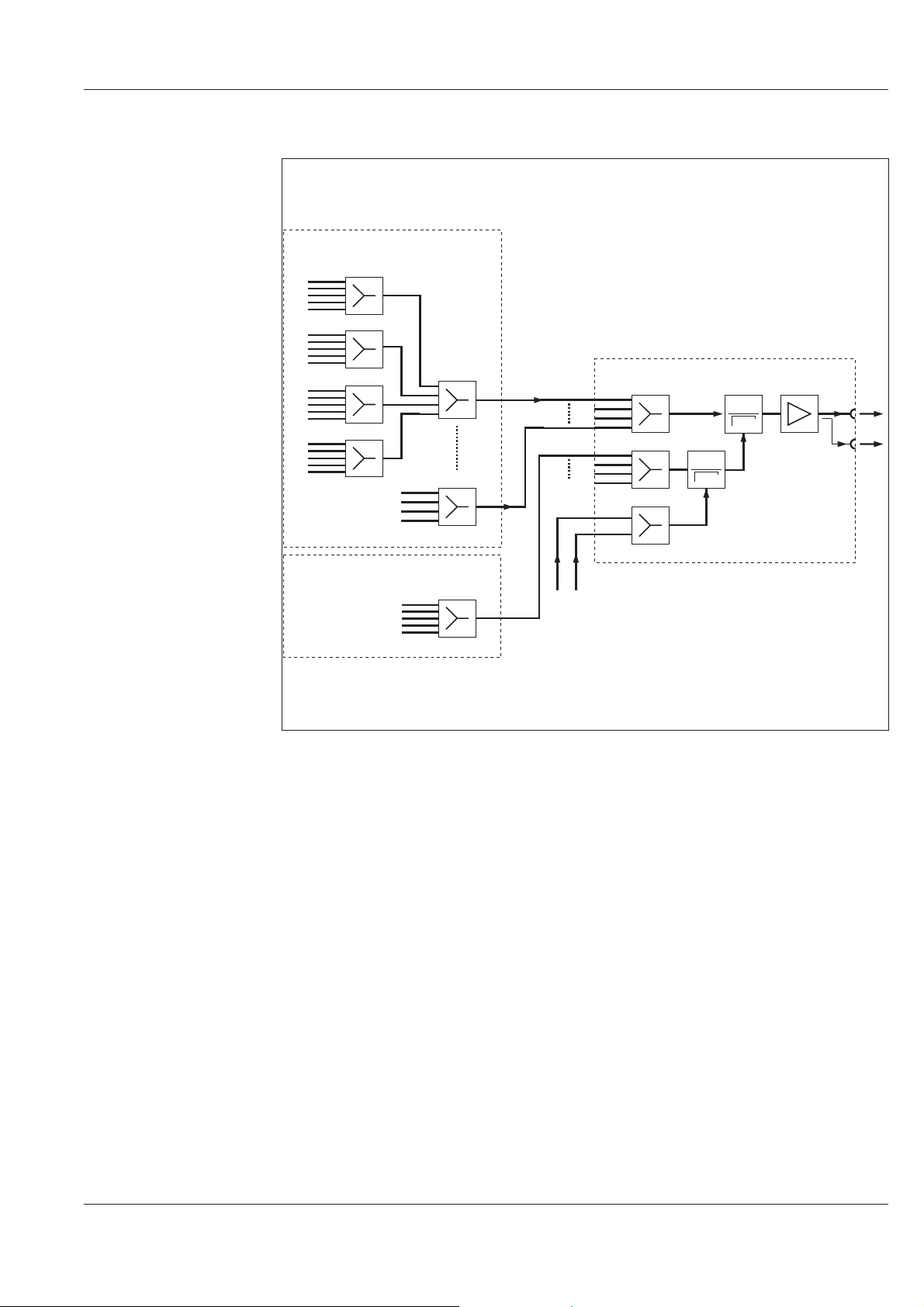
Amplifier
Block diagram
The amplifier consists of two parallel hybrids (Amplifier A, Amplifier B). The current
consumption and the temperature of both hybrids are monitored. For monitoring the
temperature an alarm and warning threshold can be set. The nominal temperature
range of the amplifier is -10oCupto+55oC.
TV signals
or
QAM signals
FM signals
Wobbler or
Pilot
frequency
RF 1 e
RF 2 e
RF 3 e
RF 4 e
RF 5 e
RF 6 e
RF 7 e
RF 8 e
RF 9 e
RF 10 e
Output amplifier
Power Supply
Mains 1
Mains 2
230/115 VAC
230/115 VAC
Amplifier A
Amplifier B
Ethernet
Monitoring/
Control
RS 232
Alarms
LCD/
Keyboard
RF a
RF OUT m
RF OUT m
OUT
OPA 8500
2 - 6 Output amplifier
Page 15
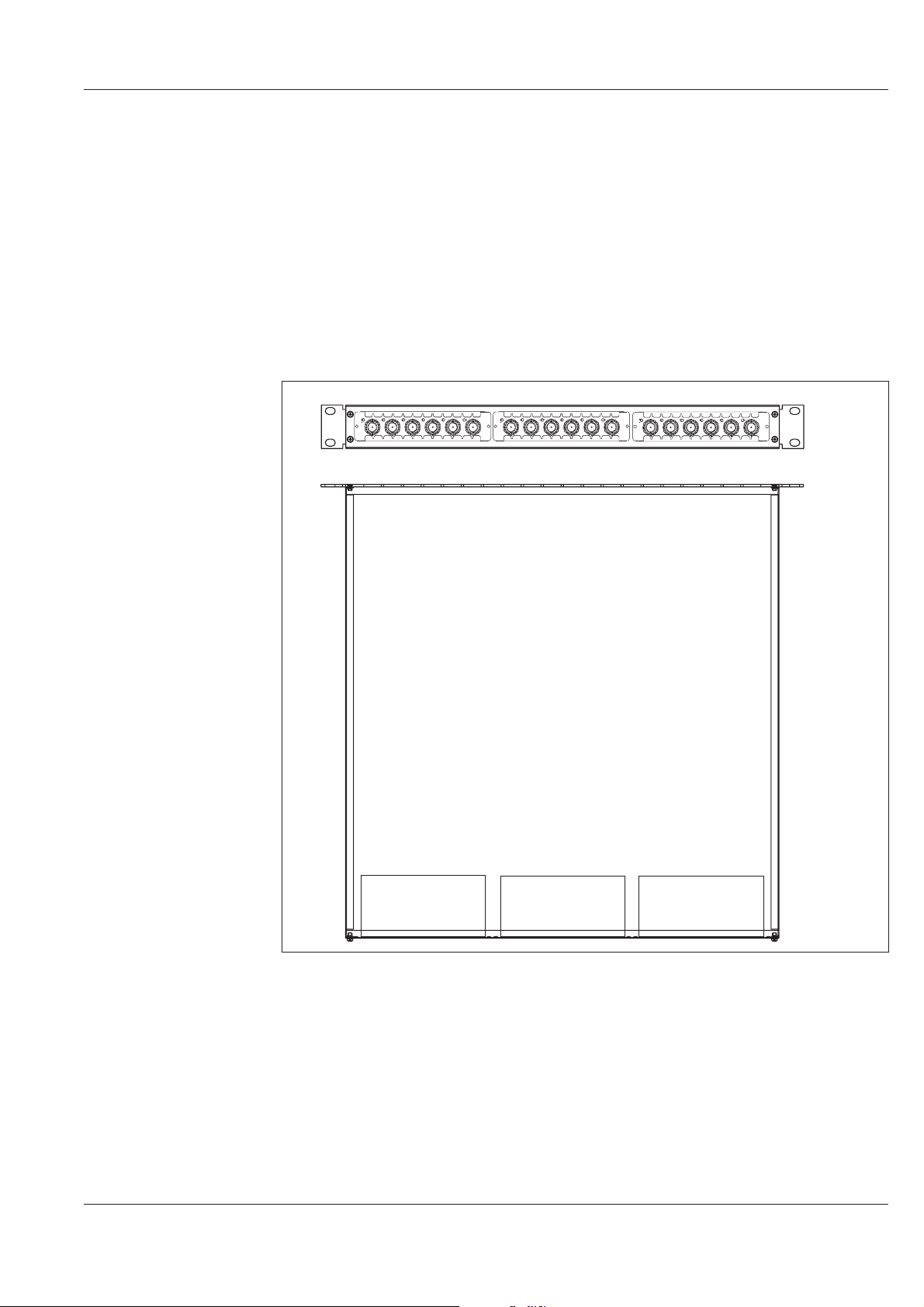
RF combiner
Putting into operation
With the passive and broadband RF-combiners the RF signals can be combined int eh
frequency range from 47 MHz up to 862 MHz.
There are following types of RF-combiners:
RF combiner RFC 8500/4 four inputs, one output
l
RF-combiner RFC 8500/5 five inputs, one output
l
The RF-combiners are mounted in the mounting frame MIO 8500. The MIO 8500
measures 1 HU and 19”. It can contain up to three RF-combiners.
Rear view
1 2 3 4 5
RF
Top view
1 2 3 4 5
RF
RFCOMBINER
1 2 3 4 5
RF
RFCOMBINER
RFCOMBINER
RF combiner RF combiner RF combiner
Mounting frame with 3 fitted RF-combiners RFC 8500/5
(Rear-view and top view)
OPA 8500
Output amplifier 2 - 7
Page 16

Putting into operation
Interfaces and operating elements
Front-panel
View
[3]
ESC
ENTER
[4]
OUT
[5]
[6]
RF
-20 d B
[7] [8]
RF
-20 d B
HIRSCHMANN
Rheinmetall Elektronik
BS 8000 series
OUTP UTAMPLIFIER
[1]
[2]
[1] Display (two lines with 20 characters each)
[2] Cursor keys
[3] ESC key
[4] ENTER key
[5] LED “OUT” lights up green, if no alarms or warnings are present.
[6] LED “ f ” lights up red for an alarm or hardware. The display also indicates
which error occurred (e. g. “ERROR: Ampl. A”).
[7] RF-monitoring output “RF OUT m -20dB” (BNC-socket; 75 ohm)
[8] RF-monitoring output “RF OUT m -20 dB” (BNC-socket, 75 ohm)
OPA 8500
2 - 8 Output amplifier
Page 17
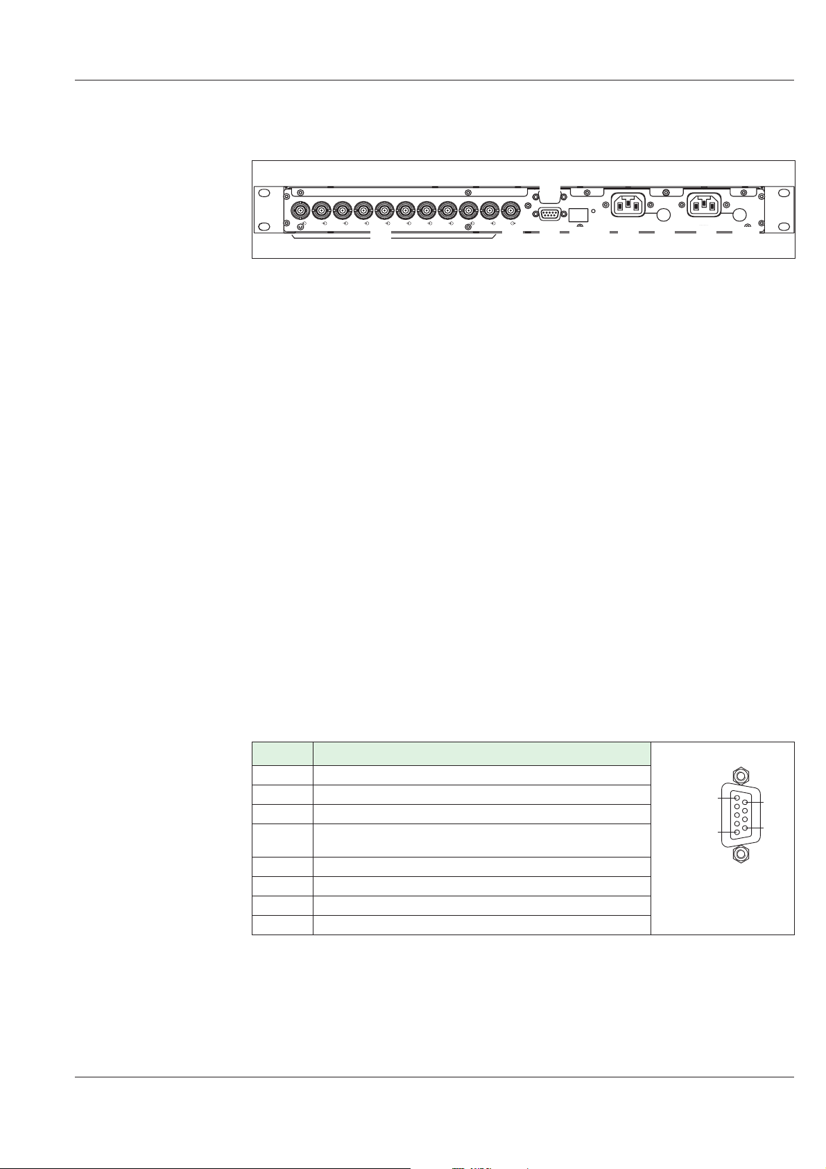
Rear-panel
View
Putting into operation
[4]
ALARMS
10 BAS E-T
RF10
[1]
RF
[2]
[3]
RS 232
RF8 RF7 RF 6 RF5 RF 4 RF 3 RF2 RF 1
RF9
[1] 10 x RF-input “RF e” (BNC-socket; 75 ohm)
[2] RF-output “RF a” (BNC-socket; 75 ohm)
[3] Remote monitoring interface “ALARMS’ (9-pole Sub-D-socket)
[4] “RS 232" interface (9 pole sub-D-socket)
LINK
[5] [7][6] [8] [9] [10]
230 V~/0 .8 AT
115V~/1.6AT
230 V~/0 .8 AT
115V~/1.6AT
MAINS 1MAINS 2
Pin-assignment RS232interface (socket)
[5] 10 Mbit/s Ethernet-interface “10BASE-T” (RJ-45 Stuart connector)
[6] LED “LINK” (lights up when Ethernet connection is ok)
[7] Mains connection “MAINS 2”
[8] Mains fuse for mains connection “MAINS 2”
[9] Mains connection “MAINS 1”
[10] Mains fuse for mains connection “MAINS 1”
Pin Remark
1 not used
2 RXD (Receiving Data)
3 TXD (Transmitting Data)
4, 6 Pin4 (DTR data terminal ready) and Pin6 (DSR data
set ready) are connected together
5 Ground
7 RTS (Request To Send)
8 CTS (Clear To Send)
9 not used
1
5
6
9
OPA 8500
Output amplifier 2 - 9
Page 18

Putting into operation
Pin-assignment
interface “ALARMS”
The double throw contacts are dimensioned for the following values:
Maximal switchable voltage 30 VDC or 42 VAC *(SELV acc. to EN60950)
l
Maximal switchable current 0,5 A
*SELV....low voltage circuit (safety extra-low voltage)
Pin Remark
1 break contact (alarm)
2 base contact (alarm or warning)
3 make contact (warning)
4 REMOTE_2 (programmable input)
5 ground
6 break contact (alarm)
7 make contact (warning)
8 REMOTE_1 (programmable input)
9
+12V / Ri = 560 Ohm
1
5
6
9
Pin-assignment 10 Mbit
Ethernet interface
ALARM
WARNUNG
REMOTE
6
1
2
3
7
2
The Ethernet interface is using a RJ-45 Stuart connector.
Pin Reamark
1 RD+ Receive data (positive)
2 RD- Receive data (negative)
3 TD+ Transmit data (positive)
6 TD- Transmit data (negative)
4/5/7/8 not used
1
OPA 8500
2 - 10 Output amplifier
Page 19

Start-up
Putting into operation
ATTENTION: Operating work must be carried out by staff with RF-knowledge.
ATTENTION: If the device is steamed up after unpacking, it must be acclimatized
at least one hour before starting operation.
ATTENTION: During operation the vents must not be covered. When mounting
the device in a rack take care that there is a gap of at least 1HU
between the devices.
NOTE: When building in the device in a rack use rails or any other suitable
mount.
Procedure
NOTE: Before operation read the chapter ”Menu operation”.
1. Check if the supply voltage shown beside the mains socket matches the mains
voltage.
ACHTUNG: A wrong mains voltage may cause a defect in the device.
Therefore check the mains voltage before connecting the module to
the mains.
Delivery state: 230V~ (Changing to 115V~ see maintenance/change
of the mains voltage)
2. Slide in the OPA 8500 into the intended place in the 19" rack.
3. Fix the module with the 4 screws on the front-panel.
4. Connect the signal cabling.
5. Connect the OPA 8500 to the mains ( boot procedure starts).
6. Adjust the contrast of the LC-display (see menu operation ”display / contrast”)
7. Check the LED´s on the front-panel.
l
LED “ f ” does not light up
l
LED “OUT” lights up
8. Set the desired warning- and alarm thresholds for the displayed values.
OPA 8500
Output amplifier 2 - 11
Page 20

Putting into operation
OPA 8500
2 - 12 Output amplifier
Page 21

Menu operation
Menu operation
OPA 8500
Output amplifier 3 - 1
Page 22

Menu operation
Menu tree
General The menu tree of the OPA 8500 shows the following main menu:
Amplifier A query of the parameter of the amplifier A
l
Amplifier B query of the parameter of the amplifier B
l
Mains query, if mains is connected
l
Status/History query of status, history and operation logs
l
Setup setting the device configuration
l
Network setting and query of the network parameters
l
Miscellaneous query of device configuration, entry of PIN-codes
l
Menu tree
Amplifier A
Amplifier B
Mains
Current
Temp.
Current
Temp.
Mains1
Mains2
OPA 8500
3 - 2 Output amplifier
Page 23

Menu tree
Status/
History
Setup
Network
Menu operation
Device status
History show
History delete
Extended messages
Changepassword
DeviceIDmenu
Date&Time
ResetAlarms/Warn.
Factorysettings
Contrast
Device PINcode
Network access
Remote control
Online users
Ethernet status
Ethernet config.
PPP status
PPP configuration
Mail settings
Miscellaneous
Module info
Temp.
OPA 8500
Output amplifier 3 - 3
Page 24

Menu operation
Menu operation
Operation
Cursor keys The OPA 8500 is operated via the key pad on the front-panel. With the cursor keys “↑”
and “↓” you can select the desired menu item. With the cursor key “→” you enter the
desired menu. With the cursor keys “↑” and “↓” you can select the desired function in
the sub-menu.
ESC-key With the ESC-key you can move one level up in the menu tree.
ENTER-key With the ENTER-key you select a setting or a measured value, and confirm an entry.
Change settings
Select the value to be changed by pressing the ENTER-key.
Position the cursor with the keys “←” resp. “→” and set the desired value with the
l
keys “↑” and “↓”.
You can exit a configuration menu in the following way:
to confirm the entry press the ENTER-key
l
to cancel the entry press the ESC-key
l
l to exit the menu press the ESC or cursor key “←”
If a value is changed, a range-window shows up on the display. The
vertical line represents the value currently set.
When changing the value, the line is moving along in the range-window. If the possible
adjustment range is left, it is indicated by an arrow. Input values outside the valid range
are not accepted. An error message “value out of range !” is displayed.
On the right margin of the display an information bar is located. The following displays
are present:
Arrow to the top resp. to the bottom : further menus can be selected by
using the cursor keys.
Arrow to the right: by using the “→”-key a submenu can be selected.
OPA 8500
3 - 4 Output amplifier
Page 25

Alarm and warning messages
By pressing the ENTER-key an alarm- and warning threshold value for a status
message or displayed value can be defined.
With the cursor keys “←” and “→” the text can be scrolled through. With the keys “↑”
and “↓” the following settings can be changed:
selection between alarm and warning message
l
selection of the message state: “EN” enables the message, “dis” disables the
l
message.
selection of condition for status indication (e.g. “if locked” or “if not locked”)
l
for display values the thresholds (upper limit, lower limit) can be selected and
l
changed. (see change settings)
Confirmation of the entries with the ENTER-key.
Menu operation
Display of an “E” : the currently selected setting can be
edited/changed.
Display of an “L” : for the currently selected status resp. value a
warning- or alarm-messge can be defined.
Password protection
Menu “Change password” You can provide the OPA 8500 with a password protection. At delivery the password is
“0000". Password query is suppressed with this password. To protect the OPA 8500
from unauthorized use you have to change the password.
However, query of the parameters and settings is possible at all times.
After entering the password (query) all settings can be changed without
restrictions. If no key is pressed during a period of 30 minutes, the device changes back
into the protected mode.
Repeated entry of the current password in the menu or the entry of a new password
causes the device to change immediately to protected mode.
NOTE: Write down the changed password. In case of loosing your
password contact the next service center.
OPA 8500
Output amplifier 3 - 5
Page 26

Menu operation
Configuration / Identification
Device identification
Menu “Device ID menu”
Device identification
Menu “Module info
For device identification in a network additional information of the device can be
stored. The following sub-settings are possible:
for example:
ID: long name [ 30 characters ] *** Hirschmann ***
l
ID: short name OPA 8500 (pre-assigned)
l
ID: rack [ 2 characters ] A1
l
ID: mainframe [ 2 characters ] 10
l
ID: location [ 20 characters ] Rankweil 3
l
ID: network name [ 30 characters ] Rheinmetall
l
ID: channel name [ 30 characters ] evaluation 8500
l
The information about the current device configuration can be queried. For each
mounted assy the following information is available:
SW-Vers Current software-version
l
GUI-V: Version of the graphical user interface
l
Ord. Nr. Hirschmann ordering number
l
Ser.Nr.: Serial number of the assy
l
G-Nr. Hardware version of the assy
l
SG-Nr. Software-version of the assy
l
Prod. Date of production
l
l Rep. Date of last repair
l Build: Number of compiling
If information is not available (e.g. the assy has no software) the message “—” is
displayed.
Status display / history / operation log
Status messages
Menu “Device status”
If status messages are present, in the main menu always the message with the
highest priority is scrolled across the upper line of the display in the main menu. In the
submenus, if a status message is present, an “!” is displayed on the left beside the
information bar (2 characters from the right)
NOTE: The submenus do not contain a status line.
After booting the device, the upper line of the display shows “OPA 8500 all ok” as well
as the name stored under “Setup\Device ID: menu\Device ID:long name”.
Further messages about current errors, alarms and warnings can be queried.
The message text can be seen by selecting the next submenu. By using the cursor
keys, the individual message texts can be read as a whole.
(exit with ESC-key)
If an error or warning message appears on the LC-display, it is likely that you will find
some additional information in the history.
OPA 8500
3 - 6 Output amplifier
Page 27

Menu operation
History / Logbuch
Menu
“History show”
“History delete”
Menu
“Extended messages”
Preset / Reset
Preset
Menu “Factory settings”
All errors, alarms and warnings that occurred as well as changes in the device settings
are stored in an operation log. The entries are listed with current time and date and a
consecutive number. The entries (max.250) can be queried. The most recent events are
stored with the lowest number.
If a threshold value is exceeded, a [+] in front of the message indicates that the valid
range was left. If the value returns into the valid range, a repeated
entry with a [-] in front of the message is shown.
The message text can be seen by selecting the next submenu. By using the cursor
keys, the individual message texts can be read as a whole.
(exit with ESC-key)
The information stored in the history can only be deleted as a whole.
Is not used in the OPA 8500 for the time being.
If the complete OPA 8500 shall be reset to the factory settings, a preset has to be
performed, which sets back all parameters and all alarm and warning thresholds to the
factory settings.
After the preset is executed, a “set up assistent” is available to make putting into
operation easier (see chapter “putting into operation” ).
Reset
Menu “Alarms/warnings”
The alarm and warning thresholds can be de-activated individually for each
measuring parameter or all alarm and warning thresholds can be de-activated at once.
Network
Network access
Menu
“Network access”
Menu “Remote control” If “Remote control” is set to “OFF”, the remote control is disabled, which means that
Menu “Online users” Indication of the present number of guest / operators / ftp connections
Network access can be disabled (e.g. in order not to cause remote error
messages when doing maintenance work or setting changes).
For the network access the following possibilities are available:
l
FREE full access, all read/write possibilities are available
(option Network Access Control)
l
Update only only an update of the flash-software can be performed
(if no software option was ordered)
remote control center is still able to receive messages from the equipment (e.g.
configuration changes made by a local operator), but cannot change configuration any
more.
OPA 8500
Output amplifier 3 - 7
Page 28

Menu operation
Ethernet Status
Menu “Ethernet status”
Network configuration
Menu “Ethernet
configuration”
If the OPA 8500 is used in a network with automatic DHCP-address
assignment, the address assigned by the server is displayed.
Interruption of an existing network connection causes the error message
“Ethernet offline".
Ethernet configuration is carried out via a LC-display. Necessary additional information
about the submenus listed below can be found in the online help.
NOTE: Before you connect the OPA 8500 to the network,
contact your network provider
For network configuration the following menu items are available:
Network Mode (setting of the DHCP address auto/man; when changing the setting,
l
the CPU on the board “Controller Assy” performs a reset)
Network IP (is assigned when DHCP is auto, to be set in manual mode)
l
Network IP Mask (is assigned when DHCP is auto, to be set in manual mode)
l
Network Gateway IP (is assigned when DHCP is auto, to be set in manual mode)
l
Network DNS IP (is assigned when DHCP is auto, to be set in manual mode)
l
Network MAC chip address of the Ethernet-controller
l
Menu “PPP status” Indication of the availability of the PPP connection (remote control RS 232)
Menu “PPP configuration” For the PPP connection (for stand-alone devices) the following menu items are
available:
l PPP baudrate Input of the baudrate for the RS 232 connection
l
PPP IP Input of the IP address of the BS8000 device
l
PPP remote IP Input of the IP adddress of the PC
l
PPP login name Input of the user ID
l
PPP login password Input of the password
Menu “Mail settings” In network operation, configuration of the mail parameters is to be carried out via the
submenus of this menu.
l
Netmail sending: Select the type(s) of messages you want to send (e.g. Errors and
warnings). If you, for example, select +INFO errors, warnings and info will be sent.
Errors will reduce the messages to error only.
l
Netmail server IP: Input of the mailserver IP
l
Netmail account: Input of the Mail account
l
Netmail dest.: Input of the email address
l
Netmail delay: Input of the delay for sending mail
l
Netmail send testmail: This menu item permits to send a test mail
OPA 8500
3 - 8 Output amplifier
Page 29

Menu operation
Display
Illumination The display illumination is automatically switched off if no key is pressed on the OPA
8500 for 15 minutes. When pressing any key the illumination switches on again.
Display contrast
Menu “Contrast”
The contrast of the display can be adapted to the light conditions in the room.
Date / Time / Temperature
Date / Time
Menu “Date & Time”
Temperature
Menu “Temp.”
The time settings stored in history are derived from this clock.
Format: [ YYYY.MM.DD HH.MM.SS ]
The temperature in the housing is measured. The current value can be queried.
PIN-Code
Release of options
Menu “Device PIN code”
If the input of a PIN-code is necessary for the release of an option, it has to be
entered in this menu. If the code is correct the message “Code accepted” is shown.
If the code is incorrect, the message says “Code not accepted”.
OPA 8500
Output amplifier 3 - 9
Page 30

Menu operation
OPA 8500
3 - 10 Output amplifier
Page 31

Maintenance
Maintenance
OPA 8500
Output amplifier 4 - 1
Page 32

Maintenance
Important notes
ATTENTION: Maintenance work must be carried out by trained staff with
ATTENTION: In case of a technical problem send your OPA 8500 to your next
NOTE: Please go to our service homepage http://service.hirschmann.at to
RF-knowledge.
service center for repair.
find other helpful information.
OPA 8500
4 - 2 Output amplifier
Page 33

Functional check
Procedure
For a functional check it is sufficient to check the nominal states of the LED´s on the
front-panel and the operating parameters on the display.
Nominal operation state
Maintenance
LED’s
LED ” f ” does not light up
l
LED ”OUT” lights up
l
OPA 8500
Output amplifier 4 - 3
Page 34

Maintenance
Help with problems
LED indication
Failure Repair
LC-display display remains
dark
red LED ” f ” lights up - An alarm was triggered. Check which alarm is active
LED ”OUT” does not light up - Restore the factory settings with PRESET and
NOTE: Eror messages, which are inserted on the LC-display, are listed in
- Press any key
- Check the power supply
- Check the mains fuse
- Change the OPA 8500
in the history Solve the problem or change the
alarm threshold.
- An existing Ethernet connection was interrupted.
Restore the connection
- Change the OPA 8500
re-configure the device.
the appendix.
OPA 8500
4 - 4 Output amplifier
Page 35

Change
Changing the mains fuse
ATTENTION: Danger of electric shock!
Disconnect the OPA 8500 from mains before changing the fuse
(both mains connectors)!
Procedure 1. Disconnect the OPA 8500 from the mains.
2. The fuse holder is located beside the mains socket. (see chapter “start-up /
interfaces and operating elements”) Open the bayonet lock of the fuse holder
with a screw driver.
3. Replace the defective fuse (5x20 mm). The fuses have, depending on the mains
voltage, the following values:
230 V mains connection 0,8 AT
l
115 V mains connection 1,6 AT
l
Maintenance
Changing the battery
ATTENTION: Danger of electric shocks !
Disconnect the OPA 8500 from the mains before
changing the battery !
WARNING: Improper change of the battery may cause an explosion.
Replacement only by the same or an equivalent type
recommended by the manufacturer !
ATTENTION: Lithium batteries must not be disposed of as domestic waste !
Send the used batteries back to the manufacturer or
supplier. Address of the manufacturer of the battery:
Firma RENATA AG
Kreuzenstr. 30
CH-4452 Itingen
NOTE: The data in the ERROR history and the note entries (when using
in the network ) get lost when the battery is changed.
OPA 8500
Output amplifier 4 - 5
Page 36

Maintenance
1. Disconnect the OPA 8500 from the mains.
2. Loose the screws on the cover and remove it.
3. Replace the empty lithium battery by a new one (lithium battery CR 2477N 3V/
1000mAh; Manufacturer: RENATA)
4. Watch out for the correct polarity of the battery !
5. Close the cover.
6. Reconnect the device to the mains.
7. Carry out a functional check ( see chapter ).
1 2
Explosionsgefahr bei
unsachgemäßem Austausch
der Batterie.
Explosion risk by improper
replacement of battery.
Lithium Batterie 3V
lithium battery 3V
+
-
SER.NUM.:XXXX /GX /SGX
CONTROLLER ASSY AS-CPU8001
ORD.NUM.:888218-001
2
12
OPA 8500
4 - 6 Output amplifier
Page 37

Choice of the mains voltage 230V~ / 115V~
The mains voltage can be changed from 230V~ to 115V~.
ATTENTION: Danger of electric shock!
Disconnect the OPA 8500 from mains before changing the fuse
(both mains connectors)!
230 V~ mains voltage cabling
1. Disconnect the OPA 8500 from the mains.
2. Loose the screws on the cover and remove it.
3. Connecting the cables of the transformators 1 and 2 - see “230V cabling”.
4. Fit the new fuse 0,8 A slow.
Maintenance
5. Close the cover.
6. Change the mains voltage on the type plate.
7. Reconnect the device to the mains.
230V~ cabling
mains 1
BC8
BC9
brown
BC7
BC10
yellow
to transformer 1 to transformer 2
BC6
yellow
mains 2
BC5
brownblack black
BC4
BC3
BC10
Transformer 1 Transformer 2
1 2
BC9
BC8
BC6
BC7
BC5
BC4
BC3
230V~: cabling of the tansformator - primary side
OPA 8500
Output amplifier 4 - 7
p
Page 38

Maintenance
115 V~ mains voltage cabling
1. Disconnect the OPA 8500 from the mains.
2. Loose the screws on the cover and remove it.
3. Connecting the cables of the transformators 1 and 2 - see “115V cabling”.
4. Fit the new fuse 1,6 A slow.
5. Close the cover.
6. Change the mains voltage on the type plate.
7. Reconnect the device to the mains.
BC10
115V~ cabling
mains 1
BC8 BC4
BC10 BC6
to transformer 1 to transformer 2
BC7 BC3
BC9 BC5
brown
mains 2
brownblack blackyellow yellow
BC9
Transformer 1 Transformer 2
115V~ cabling of the tansformator - primary side
BC8
BC7
1 2
BC6
BC5
BC4
BC3
p
OPA 8500
4 - 8 Output amplifier
Page 39

Software update
A software update can be carried out via the Ethernet interface (for headends with
several BS8000 devices) as well as via the RS232 interface and a PPP connection
(for stand-alone BS8000 devices). If a software update is necessary, all the information
about the update will be enclosed in the upgrade package.
NOTE: You can download the software update with information from the
Ordering description: Software OPA 8500/CPU-FLASH
Ordering number: 879 310-822
Ordering description: Software OPA 8500-FLASH
Ordering number: 879 310-823
Maintenance
software update section on our service homepage
http://service.hirschmann.at. Look for the ordering number given
below. The update section is protected by password. To obtain the
present password please contact service@rw.hirschmann.at. The
password is changed all three months.
Handling
Storage
Transport
Disposal
We recommend to store the OPA 8500 always in the original packaging.
Pay attention to the following parameters:
l
Temperature -20 ... +70oC
l
Relative humidity 20 … 80 %
We recommend to transport the OPA 8500 in the original packaging. Watch out that
there is no mechanical stress on the connectors and operating elements.
The device must be recycled / disposed of after duly operation according to the
national disposal regulations.
We recommend in case to contact the local authorities.
OPA 8500
Output amplifier 4 - 9
Page 40

Maintenance
Ordering information
Ordering information
Description Type Ordering number
Output amplifier OPA 8500 977 252-001
RF combiner RFC 8500/4 977 228-001
RF combiner RFC 8500/5 977 228-002
Main frame I/O unit MIO 8500 882 293-001
Ordering information options
Software Description Type Ordering number
Network Access Control NAC 8000 879 310-810
NOTE: When ordering the Network Access Control Software, both the
serial number of the OPA 8500 (see “Miscellaneous\Module info”)
and the MAC number of the Ethernet controller have to be stated in
addition to the part number.
The MAC number can be queried on the device ( see menu
operation network\Ethernet configuration\network MAC).
The software options are released with a PIN-code.
OPA 8500
4 - 10 Output amplifier
Page 41

Services
Maintenance
Austria
Germany
Benelux
France
Great Britain
Singapur
Hirschmann Austria GmbH Tel. +43-(0)5522/307 0
Oberer Paspelsweg 6-8 FAX +43-(0)5522/307 555
A-6830 RANKWEIL-BREDERIS Email info@rw.hirschmann.at
Hirschmann Electronics GmbH & Co. KG Tel. +49-(0)7127/14 0
Stuttgarter Str. 45 - 51 FAX +49-(0)7127/14 1214
D-72654 NECKARTENZLINGEN Email info@nt.hirschmann.de
Richard Hirschmann Tel. +31-(0)2944 62 555
Electronice Nederland B.V. FAX +31-(0)2944 80 639
Postbus 92 Email ibn@hirschmann.nl
NL-1380 AB WEESP
Richard Hirschmann Tel. +33-(0)1/3933 02 80
Electronique S.A. FAX +33-(0)1/3990 59 68
24, rue du Fer à Cheval, Z.I. Email erempfer@hirschmann.fr
F-95200 SARCELLES
Richard Hirschmann Tel. +44-(0)1234/34 5999
Electronics UK Ltd. FAX +44-(0)1234/35 2222
St. Martins Way Email richardhirschmann@
St. Martins Business Centre compuserve.com
GB-BEDFORD MK42 OLF
Hirschmann Electronics Pte Ltd Tel. +65 / 382 2055
3, Howard Road FAX +65 / 382 2755
Tat Hong Industrial Building #04-00 Email hirschmann.ap@pacific.net.sg
SGP-Singapore 369 578
Spain
Ungarn
USA/Canada
Internet
Hirschmann Espania S.A. Tel. +34-(0)91/746 1730
c/Trespaderne, 29 FAX +34-(0)91/746 1735
(Barrio del Aeropuerto) Email hes@hirschmann.es
Edifica Barayas 1, 2a Planta
E-28042 MADRID
Hirschmann Hungaria Kft. Tel. +36-(0)13/49 41 99
Rokolya u. 1-13 FAX +36-(0)13/29 84 53
H-1131 BUDAPEST Email hirschmann.budapest@
mail.matar.hu
Hirschmann Electronics, Inc. Tel. +1-973/830 2000
30 Hook Mountain Road - Unit 201 FAX +1-973/830 1470
PINE BROOK, N.J. 07058 Email ischnaitmann@
USA hirschmann-usa.com
http://www.hirschmann.de
http://service.hirschmann.at (e.g. Software update)
OPA 8500
Output amplifier 4 - 11
Page 42

Maintenance
OPA 8500
4 - 12 Output amplifier
Page 43

Changes
Changes
OPA 8500
Output amplifier 5 - 1
Page 44

Changes
OPA 8500
5 - 2 Output amplifier
Page 45

Appendix
Appendix
OPA 8500
Output amplifier 6 - 1
Page 46

Appendix
General data
Nominal temperature range : +5 ... +50oC
Operating temperature range : -10 ... +55oC
Storage temperature range : -20 ... +70oC
Cooling convection
Dimensions (WxDxH) :483x490x44mm
(19" main frame with 1 HU)
Mounting depth without cabling : 450 mm
Weight : max. 9 kg
Connection
Mains : 2 x compact mains plug
RF-output : BNC-socket, 75 ohm
RF-input : BNC-socket, 75 ohm
RF-monitoring output: : BNC-socket, 75 ohm
Interfaces “Alarms” : Sub-D socket 9 pole
Interfaces “RS 232” : Sub-D socket, 9 pole
10 MBit Ethernet interface : RJ-45 connector
Technical data
Power supply Mains supply:
at 115 V : 97 ... 132 VAC
at 230 V : 195 ... 264 VAC
Mains frequency: : 48 ... 63 Hz
Mains fuses:
at 230 V : 0,8 A slow
at 115 V : 1,6 A slow
Power consumption at nominal load: : max. 24 W
EMC : EN 50083-2/A1 edition 9/95 +
Safety standard : EN 60950 (edition 1997)
A1 edition 3/97
OPA 8500
6 - 2 Output amplifier
Page 47

Input RF/FM-input “RF1 e … RF10 e”:
Type / Impedance : BNC-socket / 75 ohm
Frequency range : 47 MHz … 862 MHz
Decoupling : typ. > 20 dB
Return loss : > 16 dB
Pilot-inputs
Type / impedance :BNC-socket / 75 ohm
Frequency range : 47 MHz … 862 MHz
Return loss : > 16 dB
Output RF-output “RF a”:
Type / Impedance : BNC-socket / 75 ohm
Frequency range : 47 MHz ... 862 MHz
Return loss : ≥ 16 dB
Nominal level
TV analog : 95 dBµV
DTV (256 QAM) : 91 dBµV
DTV (64 QAM) : 85 dBµV
FM :85…91dBµV
Appendix
Gain TV : 9,5 dB ± 1 dB (47 MHz)
12 dB ± 1 dB (862 MHz)
FM :3dB ± 1dB
Pilot : -12,5 dB ± 1dB
Monitoring outputs RF-monitoring outputs “RF OUT m -20 dB”
Level (acc. to RF-output) : -20 dB ± 1dB
Impedance : 75 Ohm
RF combiner RF-input, RF-output : BNC-socket / 75 ohm
Frequency range : 47 MHz … 862 MHz
OPA 8500
Output amplifier 6 - 3
Page 48

Appendix
Interfaces RS232: Pin-assignment : (see “Putting into operation \ Interfaces”)
NOTE: In order to meet the EMV-requirements a shielded cable must be
used with the RS 232 interface.
Ethernet:
10 Mbit interface “10 BASE-T”
Pin-assignment : see “Putting into operation \ Interfaces”
MPEG interface (option) : see “Putting into operation \ MPEG interface”
Remote monitoring interface “ALARMS”:
Max. switched voltage : 30 VDC or 42 VAC *(SELV acc. to EN60950)
Max. switched current : 0,5 A
Pin assignment : (see “Putting into operation \ Interfaces”)
*SELV....low voltage circuit (safety extra-low voltage)
OPA 8500
6 - 4 Output amplifier
Page 49

Error messages
The list below covers hardware errors and network errors. We have excluded all
network errors from the list, for which local repair does not seem to be feasible.
Most network errors will cause the device to perform a reset. If the network error,
however, persists, contact one of our service centers.
Appendix
OPA 8500
Output amplifier 6 - 5
Page 50

Appendix
Message: 27 MHz failure.
Cause: Unknown.
Solution: Change the device and contact one of our service centers.
Message: Amplifier A current overload.
Cause: The hybrid is defect.
Solution: Change the device and contact one of our service centers.
Message: Amplifier B current overload.
Cause: The hybrid is defect.
Solution: Change the device and contact one of our service centers.
Message: Battery empty - Data lost.
Cause: The lifetime of the battery has expired.
Solution: Replace the battery.
Message: Battery has low voltage, replace.
Cause: The lifetime of the battery has expired.
Solution: Replace the battery.
Message: Communication problem.
Cause: Unknown.
Solution: Interrupt the power supply for a few seconds.
OR Restore the factory settings in the SETUP menu and reconfigure
the device.
Message: Current overload module x.
Cause: Unknown.
Solution: Change the device and contact one of our service centers.
Message: DHCP failed _ Network disabled.
Cause: DHCP access failure.
Solution: Check the DHCP server in the network. If the DHCP server is out of
order, you can try entering a valid IP address manually. If the problem
cannot be solved this way, contact one of our service centers.
Message: DHCP failure (no valid server found).
Cause: DHCP access failure.
Solution: Check the DHCP server in the network. If the DHCP server is out of
order, you can try entering a valid IP address manually. If the problem
cannot be solved this way, contact one of our service centers.
OPA 8500
6 - 6 Output amplifier
Page 51

Message: DHCP failure, extend lease time failed.
Cause: DHCP access failure.
Solution: Check the DHCP server in the network. If the DHCP server is out of
order you can try entering a valid IP address manually. If the problem
cannot be solved this way, contact one of our service centers.
Message: DPPL failure.
Cause: The assy "DDS" has no clock or is defect.
Solution: Change the device and contact one of our service centers.
Message: DSP failure.
Cause: Unknown.
Solution: Change the device and contact one of our service centers.
Message: EEPROM failure.
Cause: Unknown.
Solution: Change the device and contact one of our service centers.
Message: Factory adjustment incomplete.
Cause: The factory settings could not be restored.
Solution: Change the device and contact one of our service centers.
Message: Fatal: Couldn_t spawn ftp-client.
Cause: Something is wrong with the ftp-client.
Solution: Change the device and contact one of our service centers.
Message: Flash data failure.
Cause: The flash is defect.
Solution: Change the device and contact one of our service centers.
Message: Flash: Failed erasing.
Cause: The flash is defect.
Solution: Change the device and contact one of our service centers.
Message: Flash: Failed writing.
Cause: The flash is defect.
Solution: Change the device and contact one of our service centers.
Message: FPGA failure.
Cause: Unknown.
Solution: Change the device and contact one of our service centers.
Message: FTP-client: Could not contact host.
Appendix
OPA 8500
Output amplifier 6 - 7
Page 52

Appendix
Cause: Something is wrong with the ftp-client.
Solution: Change the device and contact one of our service centers.
Message: General fault module x.
Cause: Unknown.
Solution: Change the device and contact one of our service centers.
Message: General hardware failure.
Cause: Maybe the device fails to access the EEPROM
OR The EEPROM checksum is not correct
OR the EEPROM data have changed.
OR The module has a wrong identification number (that means that the
hardware configuration is incorrect)
OR the adjustment bytes are incorrect.
Solution: Change the device and contact one of our service centers.
Message: I2C-bus blocked.
Cause: Communication problem.
Solution: Switch off the installation and interrupt the power supply for a few
seconds.
OR Restore the factory settings (SETUP menu) and reconfigure the
device.
Message: Incorrect mail settings.
Cause: Unknown.
Solution: Check the mail settings.
Message: Invalid module settings.
Cause: Invalid settings.
Solution: Check the module settings.
Message: Modulator failure.
Cause: Connection problem.
Solution: Check if the specified connections are provided on the slide-in places
for the options (e.g. after removal of an option)
OR Change the device.
Message: No battery found.
Cause: Connection problem.
Solution: Replace the battery.
Message: No submodule found.
Cause: Connection problem.
Solution: Check the connection to the submodule.
OPA 8500
6 - 8 Output amplifier
Page 53

Message: Option IF in/out failure.
Cause: Unknown.
Solution: Change the device and contact one of our service centers.
Message: Option ref. freq. failure.
Cause: Unknown.
Solution: Change the device and contact one of our service centers.
Message: Option RF amplifier failure.
Cause: Unknown.
Solution: Change the device and contact one of our service centers.
Message: Option stereo failure.
Cause: Unknown.
Solution: Change the device.
Message: Option video in/out failure.
Cause: Unknown.
Solution: Change the device and contact one of our service centers.
Message: Power supply failure.
Cause: Unknown.
Solution: Change the device and contact one of our service centers.
Message: QAM failure.
Cause: The problem may result from the fact that the device fails to generate
the QAM symbol clock
OR the QAM chip is defect
OR the register of the QAM chip is faulty.
Solution: Change the device and contact one of our service centers.
Message: QRF failure.
Cause: The phase-locked loop on the QRF assy or the QRF chip is defect.
Solution: Change the device and contact one of our service centers.
Message: RF-converter failure.
Cause: Uknown.
Solution: Change the device and contact one of our service centers.
Message: SAT receiver failure.
Cause: Unknown.
Solution: Change the device and contact one of our service centers.
Appendix
OPA 8500
Output amplifier 6 - 9
Page 54

Appendix
Message: SMPT: Fatal: Couldn_t spawn mailclient
Cause: Something is wrong with the mail client
Solution: Change the device and contact one of our service centers.
Message: Supply voltage failure.
Cause: Unknown.
Solution: Change the device and contact one of our service centers.
Message: Temperature too high.
Cause: The housing temperature is above 70 degrees Celsius.
Solution: Verify that the vents are not blocked.
Message: Temperature too low.
Cause: The temperature is below 0 degrees Celsius or hardware failure.
Solution: Verify that the ambient temperature of the equipment is in the
operation range of 0 ... 45 degrees Celsius
OR Change the device.
Message: Too many guests online, disconnect.
Cause: More than 5 guests have tried to log in.
Solution: Reduce the number of guests.
Message: Twisted pair disconnected / Incorrect mail settings
Cause: Broken connection
OR invalid settings.
Solution: Verify that the network connection and the mail configuration (IP
number, mail address, host, account) are correct.
Message: xx V power supply failure.
Cause: Unknown.
Solution: Change the device and contact one of our service centers.
NOTE:
NOTE:NOTE:
NOTE: Under normal conditions most network errors will cause the BS8000
to make a reset and fix the problem automatically.
OPA 8500
6 - 10 Output amplifier
 Loading...