

Page 1

Harris Broadcast is an independent company not affiliated with Harris Corporation.
HARDWARE MANUAL
Nexio G8
Edition 20131112
175-100489-00
TM
Page 2

Publication Information
© 2014 Harris Broadcast. Proprietary and Confidential.
Harris Broadcast is an independent company not affiliated with Harris Corporation.
This document and its contents are considered proprietary and confidential by Harris Broadcast. This
publication, or any part thereof, may not be reproduced in any form, by any method, for any purpose,
or in any language other than English without the written consent of Harris Broadcast. A reasonable
number of copies of this document may be made for internal use only. All others uses are illegal.
This publication is designed to assist in the use of the product as it exists on the date of publication of
this manual, and may not reflect the product at the current time or an unknown time in the future.
This publication does not in any way warrant description accuracy or guarantee the use for the
product to which it refers.
Harris Broadcast reserves the right, without notice to make such changes in equipment, design,
specifications, components, or documentation as progress may warrant to improve the performance
of the product.
Trademarks
[Product names and other appropriate trademarks, e.g. G8™, Invenio®, PowerSmart®, Versio™] are
trademarks of Harris Broadcast or its subsidiaries. Microsoft® and Windows® are registered
trademarks of Microsoft Corporation. All other trademarks and trade names are the property of their
respective companies.
Contact Information
Harris Broadcast Communications has office locations around the world. For domestic and
international location and contact information see: http://www.harrisbroadcast.com/contact-us/.
Support Contact Information
For domestic and international support contact information see:
•Support Contacts: http://www.harrisbroadcast.com/services/technical-support
•eCustomer Portal: http://support.harrisbroadcast.com
Page 3

Table of Contents
Preface
Manual Information . . . . . . . . . . . . . . . . . . . . . . . . . . . . . . . . . . . . . . . . . . . . . . . . . . . 6
Purpose . . . . . . . . . . . . . . . . . . . . . . . . . . . . . . . . . . . . . . . . . . . . . . . . . . . . . . . . . . . . . . . . . . . . . 6
Audience . . . . . . . . . . . . . . . . . . . . . . . . . . . . . . . . . . . . . . . . . . . . . . . . . . . . . . . . . . . . . . . . . . . . 6
Writing Conventions . . . . . . . . . . . . . . . . . . . . . . . . . . . . . . . . . . . . . . . . . . . . . . . . . . . . . . . . . . . . 6
Obtaining Documents . . . . . . . . . . . . . . . . . . . . . . . . . . . . . . . . . . . . . . . . . . . . . . . . . . . . . . . . . . . 6
Unpacking/Shipping Information . . . . . . . . . . . . . . . . . . . . . . . . . . . . . . . . . . . . . . . . 7
Safety Standards and Compliances . . . . . . . . . . . . . . . . . . . . . . . . . . . . . . . . . . . . . 8
Safety Terms and Symbols . . . . . . . . . . . . . . . . . . . . . . . . . . . . . . . . . . . . . . . . . . . . . . . . . . . . . . 8
Restriction on Hazardous Substances (RoHS) Directive . . . . . . . . . . . . . . . . . . . . . . . . . . . . . . . . 8
Waste from Electrical and Electronic Equipment (WEEE) Directive . . . . . . . . . . . . . . . . . . . . . . . 9
Safety Guidelines . . . . . . . . . . . . . . . . . . . . . . . . . . . . . . . . . . . . . . . . . . . . . . . . . . . 10
Electrical Safety Guidelines . . . . . . . . . . . . . . . . . . . . . . . . . . . . . . . . . . . . . . . . . . . . . . . . . . . . . 10
Power Cords . . . . . . . . . . . . . . . . . . . . . . . . . . . . . . . . . . . . . . . . . . . . . . . . . . . . . . . . . . . . . . 10
General Electrical Safety Guidelines . . . . . . . . . . . . . . . . . . . . . . . . . . . . . . . . . . . . . . . . . . . 10
General Safety Guidelines . . . . . . . . . . . . . . . . . . . . . . . . . . . . . . . . . . . . . . . . . . . . . . . . . . . . . . 11
ESD Safety Guidelines . . . . . . . . . . . . . . . . . . . . . . . . . . . . . . . . . . . . . . . . . . . . . . . . . . . . . . . . . 11
Operation Safety Guidelines . . . . . . . . . . . . . . . . . . . . . . . . . . . . . . . . . . . . . . . . . . . . . . . . . . . . 12
Chassis Components
Overview . . . . . . . . . . . . . . . . . . . . . . . . . . . . . . . . . . . . . . . . . . . . . . . . . . . . . . . . . . 16
Front Panel . . . . . . . . . . . . . . . . . . . . . . . . . . . . . . . . . . . . . . . . . . . . . . . . . . . . . . . . 17
Inner Front Panel . . . . . . . . . . . . . . . . . . . . . . . . . . . . . . . . . . . . . . . . . . . . . . . . . . . . . . . . . . . . . 17
Front LED Panel . . . . . . . . . . . . . . . . . . . . . . . . . . . . . . . . . . . . . . . . . . . . . . . . . . . . . . . . . . . 18
Front Panel Buttons . . . . . . . . . . . . . . . . . . . . . . . . . . . . . . . . . . . . . . . . . . . . . . . . . . . . . . . . 19
Front Panel LEDs . . . . . . . . . . . . . . . . . . . . . . . . . . . . . . . . . . . . . . . . . . . . . . . . . . . . . . . . . . 19
SAS2/SATA LEDs . . . . . . . . . . . . . . . . . . . . . . . . . . . . . . . . . . . . . . . . . . . . . . . . . . . . . . . . . . 20
Copyright © 2014 Harris Broadcast
Proprietary and Confidential
iTable of Contents
G8 Hardware Installation Manual
Page 4

Back Panel . . . . . . . . . . . . . . . . . . . . . . . . . . . . . . . . . . . . . . . . . . . . . . . . . . . . . . . . . 21
Back Panel Components . . . . . . . . . . . . . . . . . . . . . . . . . . . . . . . . . . . . . . . . . . . . . . . . . . . . . . . 21
Motherboard I/O . . . . . . . . . . . . . . . . . . . . . . . . . . . . . . . . . . . . . . . . . . . . . . . . . . . . . . . . . . . . . . 21
G411 Broadcast I/O . . . . . . . . . . . . . . . . . . . . . . . . . . . . . . . . . . . . . . . . . . . . . . . . . . . . . . . . . . . 22
AES Ponytail Cable . . . . . . . . . . . . . . . . . . . . . . . . . . . . . . . . . . . . . . . . . . . . . . . . . . . . . . . . . 23
G411 Specifications . . . . . . . . . . . . . . . . . . . . . . . . . . . . . . . . . . . . . . . . . . . . . . . . . . . . . . . . . . . 23
Power Supply Modules . . . . . . . . . . . . . . . . . . . . . . . . . . . . . . . . . . . . . . . . . . . . . . . . . . . . . . . . 23
Installation and Setup
Overview . . . . . . . . . . . . . . . . . . . . . . . . . . . . . . . . . . . . . . . . . . . . . . . . . . . . . . . . . . 26
Chassis Components Installation . . . . . . . . . . . . . . . . . . . . . . . . . . . . . . . . . . . . . . 27
Important Safety Guidelines . . . . . . . . . . . . . . . . . . . . . . . . . . . . . . . . . . . . . . . . . . . . . . . . . . . . . 27
Safety Steps . . . . . . . . . . . . . . . . . . . . . . . . . . . . . . . . . . . . . . . . . . . . . . . . . . . . . . . . . . . . . . 27
Installation Tools . . . . . . . . . . . . . . . . . . . . . . . . . . . . . . . . . . . . . . . . . . . . . . . . . . . . . . . . . . . . . 27
Install Hard Drives . . . . . . . . . . . . . . . . . . . . . . . . . . . . . . . . . . . . . . . . . . . . . . . . . . . . . . . . . . . . 28
Remove Hard Drive Trays from the Chassis . . . . . . . . . . . . . . . . . . . . . . . . . . . . . . . . . . . . . 28
Install Hard Drive into a Drive Carrier . . . . . . . . . . . . . . . . . . . . . . . . . . . . . . . . . . . . . . . . . . . 28
Remove the Chassis Cover . . . . . . . . . . . . . . . . . . . . . . . . . . . . . . . . . . . . . . . . . . . . . . . . . . . . . 31
System Fans . . . . . . . . . . . . . . . . . . . . . . . . . . . . . . . . . . . . . . . . . . . . . . . . . . . . . . . . . . . . . . . . 32
Replace a System Fan . . . . . . . . . . . . . . . . . . . . . . . . . . . . . . . . . . . . . . . . . . . . . . . . . . . . . . 32
Replace the Onboard CR2032 Battery . . . . . . . . . . . . . . . . . . . . . . . . . . . . . . . . . . . . . . . . . . . . 33
Power Supply . . . . . . . . . . . . . . . . . . . . . . . . . . . . . . . . . . . . . . . . . . . . . . . . . . . . . . . . . . . . . . . . 33
Change the Power Supply . . . . . . . . . . . . . . . . . . . . . . . . . . . . . . . . . . . . . . . . . . . . . . . . . . . 34
Install the Power Distributor . . . . . . . . . . . . . . . . . . . . . . . . . . . . . . . . . . . . . . . . . . . . . . . . . . 34
Chassis Rack Installation . . . . . . . . . . . . . . . . . . . . . . . . . . . . . . . . . . . . . . . . . . . . . 36
Rack Location . . . . . . . . . . . . . . . . . . . . . . . . . . . . . . . . . . . . . . . . . . . . . . . . . . . . . . . . . . . . . . . 36
Prepare for Setup . . . . . . . . . . . . . . . . . . . . . . . . . . . . . . . . . . . . . . . . . . . . . . . . . . . . . . . . . . . . . 36
Choosing a Setup Location . . . . . . . . . . . . . . . . . . . . . . . . . . . . . . . . . . . . . . . . . . . . . . . . . . . 36
Warnings and Precautions . . . . . . . . . . . . . . . . . . . . . . . . . . . . . . . . . . . . . . . . . . . . . . . . . . . . . . 36
Rack Precautions . . . . . . . . . . . . . . . . . . . . . . . . . . . . . . . . . . . . . . . . . . . . . . . . . . . . . . . . . . 36
General System Precautions . . . . . . . . . . . . . . . . . . . . . . . . . . . . . . . . . . . . . . . . . . . . . . . . . 36
Rack Mounting Considerations . . . . . . . . . . . . . . . . . . . . . . . . . . . . . . . . . . . . . . . . . . . . . . . . . . 37
Ambient Operating Temperature . . . . . . . . . . . . . . . . . . . . . . . . . . . . . . . . . . . . . . . . . . . . . . 37
Reduced Airflow . . . . . . . . . . . . . . . . . . . . . . . . . . . . . . . . . . . . . . . . . . . . . . . . . . . . . . . . . . . 37
Mechanical Loading . . . . . . . . . . . . . . . . . . . . . . . . . . . . . . . . . . . . . . . . . . . . . . . . . . . . . . . . 37
Circuit Overloading . . . . . . . . . . . . . . . . . . . . . . . . . . . . . . . . . . . . . . . . . . . . . . . . . . . . . . . . . 37
Reliable Ground . . . . . . . . . . . . . . . . . . . . . . . . . . . . . . . . . . . . . . . . . . . . . . . . . . . . . . . . . . . 38
Rack Mounting . . . . . . . . . . . . . . . . . . . . . . . . . . . . . . . . . . . . . . . . . . . . . . . . . . . . . . . . . . . . . . . 38
ii Table of Contents
G8 Hardware Installation Manual
Proprietary and Confidential
Copyright © 2014 Harris Broadcast
Page 5

Identify the Sections of the Rack Rails . . . . . . . . . . . . . . . . . . . . . . . . . . . . . . . . . . . . . . . . . . 38
Lock Tabs . . . . . . . . . . . . . . . . . . . . . . . . . . . . . . . . . . . . . . . . . . . . . . . . . . . . . . . . . . . . . . . . 38
Release the Inner Rail from the Outer Rails . . . . . . . . . . . . . . . . . . . . . . . . . . . . . . . . . . . . . . 39
Install the Inner Rails on the Chassis . . . . . . . . . . . . . . . . . . . . . . . . . . . . . . . . . . . . . . . . . . . 39
Install the Outer Rails on the Rack . . . . . . . . . . . . . . . . . . . . . . . . . . . . . . . . . . . . . . . . . . . . . 41
Standard Chassis Installation . . . . . . . . . . . . . . . . . . . . . . . . . . . . . . . . . . . . . . . . . . . . . . . . . . . . 42
BIOS Error Beep Codes . . . . . . . . . . . . . . . . . . . . . . . . . . . . . . . . . . . . . . . . . . . . . . 44
Non-Fatal and Fatal Errors . . . . . . . . . . . . . . . . . . . . . . . . . . . . . . . . . . . . . . . . . . . . . . . . . . . . . . 44
Setup and Configuration
Overview . . . . . . . . . . . . . . . . . . . . . . . . . . . . . . . . . . . . . . . . . . . . . . . . . . . . . . . . . . 46
Disk Subsystems . . . . . . . . . . . . . . . . . . . . . . . . . . . . . . . . . . . . . . . . . . . . . . . . . . . 47
Disk Subsystems Organization . . . . . . . . . . . . . . . . . . . . . . . . . . . . . . . . . . . . . . . . . . . . . . . . . . 47
Drive Configuration . . . . . . . . . . . . . . . . . . . . . . . . . . . . . . . . . . . . . . . . . . . . . . . . . . . . . . . . . . . 47
GPI/AfterBurner 4 . . . . . . . . . . . . . . . . . . . . . . . . . . . . . . . . . . . . . . . . . . . . . . . . . . . 49
Fanout Cable Pinouts (AB4 to RJ12) . . . . . . . . . . . . . . . . . . . . . . . . . . . . . . . . . . . . . . . . . . . . . . 49
AB4 Cabling Using Fanout Cables . . . . . . . . . . . . . . . . . . . . . . . . . . . . . . . . . . . . . . . . . . . . . . . . 50
Fanout Cable Lengths . . . . . . . . . . . . . . . . . . . . . . . . . . . . . . . . . . . . . . . . . . . . . . . . . . . . . . . 51
Pinout Reference . . . . . . . . . . . . . . . . . . . . . . . . . . . . . . . . . . . . . . . . . . . . . . . . . . . . . . . . . . . . . 52
AB4 RJ12 GPI PINOUT . . . . . . . . . . . . . . . . . . . . . . . . . . . . . . . . . . . . . . . . . . . . . . . . . . . . . 52
Preview Display . . . . . . . . . . . . . . . . . . . . . . . . . . . . . . . . . . . . . . . . . . . . . . . . . . . . . 53
Preview Display Setup . . . . . . . . . . . . . . . . . . . . . . . . . . . . . . . . . . . . . . . . . . . . . . . . . . . . . . . . . 53
Maintenance
Overview . . . . . . . . . . . . . . . . . . . . . . . . . . . . . . . . . . . . . . . . . . . . . . . . . . . . . . . . . . 56
Hot Swap Power Supplies . . . . . . . . . . . . . . . . . . . . . . . . . . . . . . . . . . . . . . . . . . . . 57
To replace the failed power supply module . . . . . . . . . . . . . . . . . . . . . . . . . . . . . . . . . . . . . . . . . 57
System Restore . . . . . . . . . . . . . . . . . . . . . . . . . . . . . . . . . . . . . . . . . . . . . . . . . . . . . 58
Create a Restore Point . . . . . . . . . . . . . . . . . . . . . . . . . . . . . . . . . . . . . . . . . . . . . . . . . . . . . . . . . 58
System Restore . . . . . . . . . . . . . . . . . . . . . . . . . . . . . . . . . . . . . . . . . . . . . . . . . . . . . . . . . . . . . . 59
Prevent Damage and Malfunction . . . . . . . . . . . . . . . . . . . . . . . . . . . . . . . . . . . . . . 63
Hardware . . . . . . . . . . . . . . . . . . . . . . . . . . . . . . . . . . . . . . . . . . . . . . . . . . . . . . . . . . . . . . . . . . . 63
Anti-Virus Software . . . . . . . . . . . . . . . . . . . . . . . . . . . . . . . . . . . . . . . . . . . . . . . . . . . . . . . . . . . 63
Operating System Updates . . . . . . . . . . . . . . . . . . . . . . . . . . . . . . . . . . . . . . . . . . . . . . . . . . . . . 63
Automatic Updates . . . . . . . . . . . . . . . . . . . . . . . . . . . . . . . . . . . . . . . . . . . . . . . . . . . . . . . . . . . . 64
Copyright © 2014 Harris Broadcast
Proprietary and Confidential
G8 Hardware Installation Manual
iiiTable of Contents
Page 6

Specifications
Overview . . . . . . . . . . . . . . . . . . . . . . . . . . . . . . . . . . . . . . . . . . . . . . . . . . . . . . . . . . 66
Specifications . . . . . . . . . . . . . . . . . . . . . . . . . . . . . . . . . . . . . . . . . . . . . . . . . . . . . . 67
System Technical Specifications . . . . . . . . . . . . . . . . . . . . . . . . . . . . . . . . . . . . . . . . . . . . . . . . . 67
G411 General Specifications . . . . . . . . . . . . . . . . . . . . . . . . . . . . . . . . . . . . . . . . . . . . . . . . . . . . 68
G411 HD/SDI Video Specifications . . . . . . . . . . . . . . . . . . . . . . . . . . . . . . . . . . . . . . . . . . . . . . . 69
G411 AES Audio Specifications . . . . . . . . . . . . . . . . . . . . . . . . . . . . . . . . . . . . . . . . . . . . . . . . . . 70
G411 Genlock (Ref In) Specifications . . . . . . . . . . . . . . . . . . . . . . . . . . . . . . . . . . . . . . . . . . . . . 71
Power Supply Specifications . . . . . . . . . . . . . . . . . . . . . . . . . . . . . . . . . . . . . . . . . . . . . . . . . . . . 72
Index . . . . . . . . . . . . . . . . . . . . . . . . . . . . . . . . . . . . . . . . . . . . . . . . . 73
iv Table of Contents
G8 Hardware Installation Manual
Proprietary and Confidential
Copyright © 2014 Harris Broadcast
Page 7

Preface
Page 8

Manual Information
Purpose
Audience
Writing
Conventions
This manual details the features, installation, operation, maintenance, and
specifications of your Inscriber G8 system.
This manual is written for engineers, technicians, and operators responsible for
the system installation and setup.
This manual adheres to the following writing conventions.
Table ii-1. Writing Conventions
Term or Convention Description
CAPS Indicates a specific key on the keyboard, such
as ENTER, TAB, CTRL, ALT, DELETE
Code
>
hyperlink Indicates a jump to another location within the
Indicates variables or command-line entries,
such as a DOS entry or something you type
into a field.
Indicates the direction of navigation through a
hierarchy of menus and windows.
electronic document or elsewhere
Obtaining
Documents
6Preface
G8 Hardware Installation Manual
Internet address
Product documents can be viewed or downloaded from the Harris Broadcast
website at
customer service representative to request a document.
http://support.harrisbroadcast.com. Alternatively, contact your
Proprietary and Confidential
Indicates a jump to a website or URL
Copyright © 2014 Harris Broadcast
Page 9

Unpacking/Shipping Information
Your system has been carefully inspected, tested, and calibrated prior to shipment to ensure years of stable
and trouble free service.
Before you install and configure your Inscriber G8 system, follow these steps:
1 Check equipment for any visible damage that may have occurred during
transit.
2 Confirm that you have received all items listed on the packing list.
3 Contact your sales representative if any parts are missing.
4 Contact the carrier if any item is damaged.
5 Remove all packaging material from the product and its associated
components before you install the unit.
Keep at least one set of original packaging, in the event that you need to return
a product for servicing. If the original packaging is not available, you can
purchase replacement packaging at a modest cost or supply your own
packaging as long as it meets the following criteria:
• The packaging must be able to withstand the weight of the product.
• The product must be held rigid within the packaging.
• There must be at least two inches (5 cm) of space between the product and
the container.
• The corners of the product must be protected.
Copyright © 2014 Harris Broadcast
Proprietary and Confidential
7Preface
G8 Hardware Installation Manual
Page 10
Safety Standards and Compliances
Safety Terms and Symbols
This manual uses the following safety terms and symbols to identify certain
conditions or practices.
Table ii-2. Safety Terms and Symbols
WARNING: Identifies conditions or practices that can
result in personal injury or loss of life—high voltage is
present. Uninsulated dangerous voltage within the product’s
enclosure may be sufficient to constitute a risk of electric
shock to persons.
CAUTION: Identifies conditions or practices that can result
in damage to the equipment or other property. Important
operating and maintenance (servicing) instructions are
included in the literature accompanying the product.
Restriction on Hazardous Substances (RoHS) Directive
Directive 2002/95/EC – commonly known as the European Union (EU)
Restriction on Hazardous Substances (RoHS) – sets limits on the use of certain
substances found in electrical and electronic equipment. The Directive took
effect on July 1, 2006, and it refers to the following hazardous substances:
• Lead (Pb)
•Mercury (Hg)
•Cadmium (Cd)
• Hexavalent Chromium (Cr-V1)
• Polybrominated Biphenyls (PBB)
• Polybrominated Diphenyl Ethers (PBDE)
All relevant Harris Broadcast products either comply with the legislation or are
exempt. For example, spare parts supplied for the repair and upgrade of
equipment sold before July 1, 2006 are exempt from the legislation.
Figure ii-1. RoHS Compliant Symbol
8Preface
G8 Hardware Installation Manual
Proprietary and Confidential
Copyright © 2014 Harris Broadcast
Page 11
Waste from Electrical and Electronic Equipment (WEEE) Directive
The European Union (EU) Directive 2002/96/EC on Waste from Electrical and
Electronic Equipment (WEEE) deals with the collection, treatment, recovery,
and recycling of electrical and electronic waste products. The objective of the
WEEE Directive is to assign the responsibility for the disposal of associated
hazardous waste to either the producers or users of these products. Producers
or users are required to recycle electrical and electronic equipment at end of its
useful life, and must not dispose of the equipment in landfills or by using other
unapproved methods.
In accordance with this EU Directive, Harris Broadcast has affixed labels
indicating that such products must be properly recycled. Contact your local
Harris Broadcast sales representative for information on returning these
products for recycling. Harris Broadcast equipment that complies with the EU
directive will be marked with a WEEE-compliant symbol, as shown in Figure
ii-2.
Copyright © 2014 Harris Broadcast
Figure ii-2. WEEE Compliance Symbol
Proprietary and Confidential
G8 Hardware Installation Manual
9Preface
Page 12
Safety Guidelines
Warning
Warning
This unit is for use in restricted access only. Adhere to the following safety guidelines to avoid personal injury
or damage to your system.
Electrical Safety Guidelines
Power Cords
• Use the exact type of power cords as required.
• Be sure to use power cord(s) that came with safety certifications.
To avoid electrical shock, check
the power cords properly.
• The power cord(s) must be compliant with the AC voltage requirements in
your region.
• The power cord plug cap must have an electrical current rating that is at
least 125% of the electrical current rating of this product.
• The power cord plug cap that plugs into the AC receptacle on the power
supply must be an IEC 320, sheet C13, type female connector.
• Be sure to disconnect the power supply before accessing the G8 chassis or
its components.
Adhere to the following
Electrical Safety Guidelines to
avoid possible damages to the
system or injury to yourself.
• Plug the Power cord(s) into a socket that is properly grounded before
turning on the power.
General Electrical Safety Guidelines
• Be aware of the locations of the power switches on the chassis and in the
room, so you can disconnect the power supply if an accident occurs.
• Take extra precautionary measures when working with high voltage
components. It is not recommended to work alone.
• Before removing or installing main system components, be sure to
disconnect the power first. Turn off the system before you disconnect the
power supply.
• Use only one hand when working with powered-on electrical equipment to
avoid possible electrical shock.
• Use rubber mats specifically designed as electrical insulators when working
with computer systems.
• The power supply or power cord must include a grounding plug and must
be plugged into grounded outlets.
10 Preface
G8 Hardware Installation Manual
Proprietary and Confidential
Copyright © 2014 Harris Broadcast
Page 13
• Motherboard Battery: CAUTION – To avoid possible explosion, make sure
Warning
Caution
you do not install the onboard battery upside down. The positive side must
face up on the motherboard. This battery must be replaced only with the
same or an equivalent type.
• CD-ROM Laser: CAUTION – Do not open the enclosures of power
supplies or CD ROM to avoid injury.
General Safety Guidelines
• Keep the area around the G8 chassis clean and free of clutter.
• To avoid injuries to your back, be sure to use your leg muscles, keep your
Adhere to the following General
Safety Guidelines to ensure
your personal safety.
back straight, and bend your knees when lifting the system.
• Avoid wearing loose clothing to prevent it from coming into contact with
power circuits.
• After removing the components or chassis covers from the system, place
them on a table for safeguard.
• Be sure to remove any jewelry or metal objects before working on the
chassis to avoid short circuits should these objects come into contact with
power circuits.
• After accessing the interior of the chassis, be sure to close the chassis with
ESD Safety Guidelines
The following measures are generally sufficient to protect against Electric
Statics Discharge (ESD).
Electric Static Discharge (ESD)
can damage electronic
components. To prevent
damage to your system board, it
is important to handle it very
carefully.
• Do not use mats designed to decrease electrostatic discharge as protection
• Use a grounded wrist strap designed to prevent static discharge.
• Keep all components and printed circuit boards (PCBs) in their anti-static
• Touch a grounded metal object before removing the board from the
• Do not let components or PCBs come into contact with your clothing,
chassis covers and secure the chassis to the racks with screws.
from electrical shock. Instead, use rubber mats that have been specifically
designed as electrical insulators.
bags until ready for use.
anti-static bag.
which may retain a charge even if you are wearing a wrist strap.
Copyright © 2014 Harris Broadcast
Proprietary and Confidential
11Preface
G8 Hardware Installation Manual
Page 14
• Handle a board by its edges only; do not touch its components, peripheral
Warning
Caution
chips, memory modules, or contacts.
• When handling chips or modules, avoid touching their pins.
• Put the motherboard and peripherals back into their anti-static bags when
not in use.
• For grounding purposes, make sure your computer chassis provides
excellent conductivity between the power supply, the case, the mounting
fasteners, and the motherboard.
Operation Safety Guidelines
Before accessing the G8 chassis:
1 Turn off all peripheral devices connected to the G8 chassis.
2 Press the power button to power off the system.
To avoid personal injury and
property damage, please
carefully follow all the
Operation Safety Guidelines
precisely.
3 Unplug all power cords from the system or the wall outlets.
4 Disconnect all the cables and label the cables for easy identification.
5 Use a grounded wrist strap designed to prevent static discharge when
handling components.
For proper cooling, make sure
to chassis covers are properly
installed before turning on the
system. If this rule is not strictly
followed, warranty may become
void. Do not open the casing of
a power supply. Power supplies
can only be accessed and
serviced by a qualified
technician of the manufacturer.
Removing the chassis covers:
After completing the above steps, you can remove the covers and install
components/peripheral devices into the G8 chassis. See ”Chassis Components
Installation” on page 27 for details.
1 Unlock and remove the screws and fasteners to remove the cover or
components.
2 Save all the screws and fasteners for later use. (If necessary, label these
screws or fasteners for easy identification.)
3 Follow the instructions in ”Remove the Chassis Cover” on page 31 to
remove the chassis cover.
Reinstalling the chassis covers:
To maintain proper system cooling and airflow, do not operate the system
without installing all chassis covers back onto the chassis. To reinstall the
chassis covers, please follow the steps listed below:
1 Make sure that all components and devices are securely fastened on the
chassis and that there are no loose parts/screws inside the chassis.
12 Preface
G8 Hardware Installation Manual
Proprietary and Confidential
Copyright © 2014 Harris Broadcast
Page 15

2 Make sure that all cables are properly connected to the connectors and
ports.
3 Use the original screws or fasteners to install the covers to the chassis.
4 Be sure to lock to the chassis or the system to prevent unauthorized
access.
5 For proper cooling, enclose the chassis with covers before operating the
system.
Before installing the chassis into a rack:
1 Make sure that the rack is securely anchored onto an unmovable surface or
structure.
2 Unplug the power cord(s) of the rack before installing the chassis.
3 Make sure that the system is adequately supported and that all components
are securely fastened to the chassis to prevent them from falling off the
chassis.
4 Be sure to install an AC Power Disconnect for the entire rack assembly.
Clearly mark the Power Disconnect.
5 The rack assembly must be properly grounded to avoid electric shock.
6 The rack assembly must provide sufficient airflow to the chassis for proper
cooling.
Copyright © 2014 Harris Broadcast
Proprietary and Confidential
13Preface
G8 Hardware Installation Manual
Page 16

14 Preface
G8 Hardware Installation Manual
Proprietary and Confidential
Copyright © 2014 Harris Broadcast
Page 17

Chapter 1
Chassis Components
Page 18

Overview
This chapter provides an introduction to your G8 System, and includes the
following topics:
• “Front Panel” on page 17
• “Back Panel” on page 21
16 Chapter 1 | Chassis Components
G8 Hardware Installation Manual
Proprietary and Confidential
Copyright © 2014 Harris Broadcast
Page 19
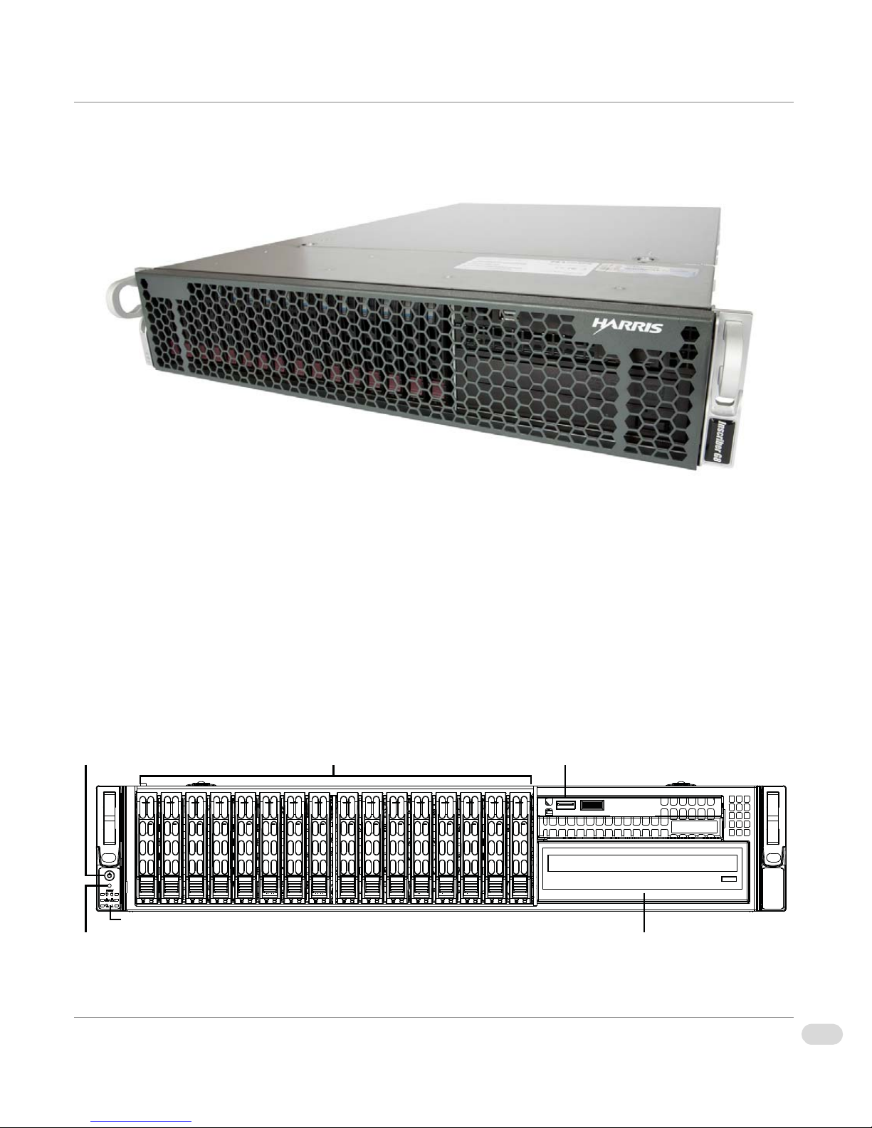
Front Panel
Power button USBRemoveable Drive Trays
CD/DVD-RWReset button
LED Panel
The following information describes the front panel components for G8 systems.
Figure 1-1. G8 Outer Front Panel
Inner Front Panel
The G8 inner front panel includes the following:
• System Power (on/off) button
• System Reset (restart) button
• LED indicators
• Hot-swappable hard disk drives
•One USB port
• CD/DVD-RW
Copyright © 2014 Harris Broadcast
Figure 1-2: G8 Inner Front Panel
Proprietary and Confidential
17Chapter 1 | Chassis Components
G8 Hardware Installation Manual
Page 20
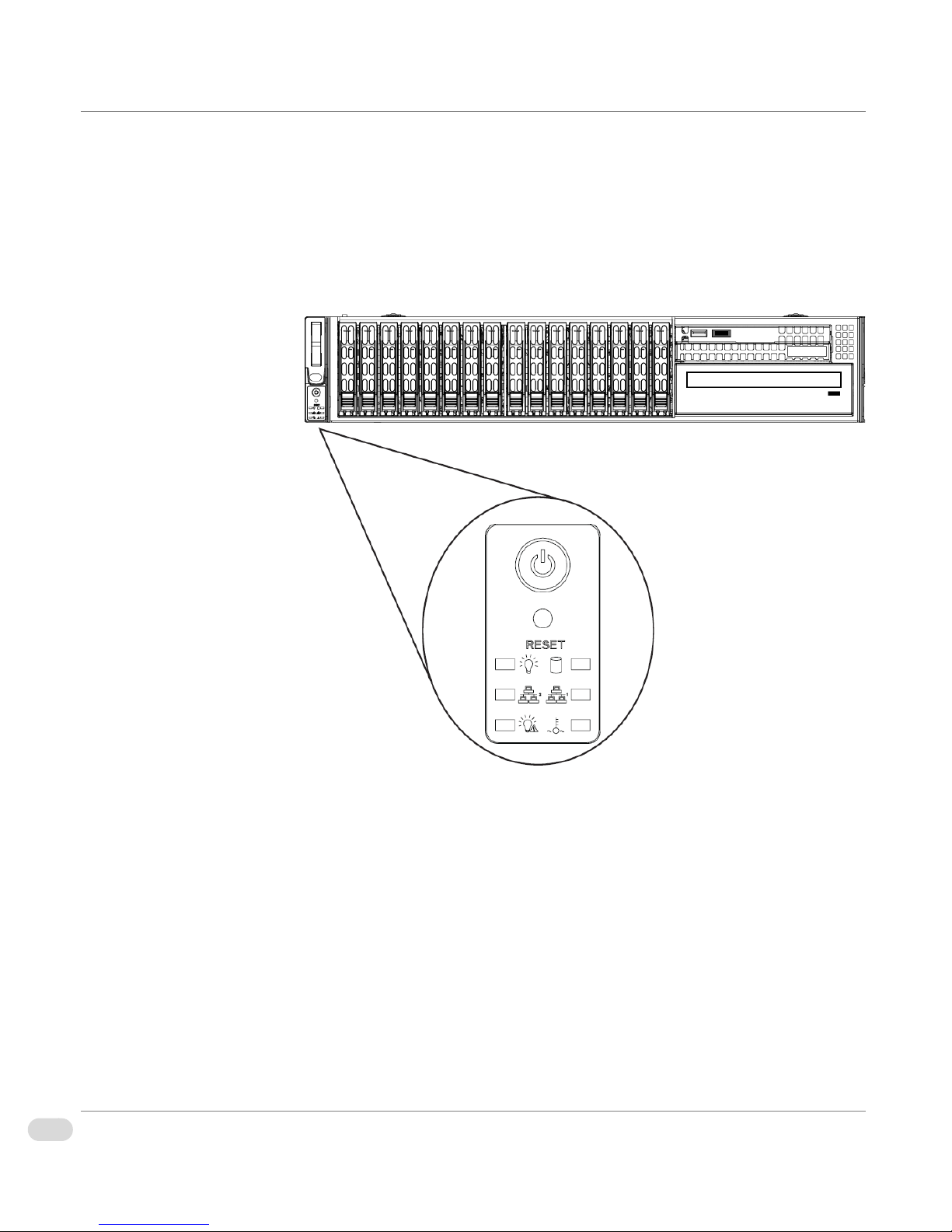
Front LED Panel
There are several LEDs on the LED panel as well as other LEDs on the drive
carriers to keep you constantly informed of the overall status of the system, as
well as the activity and health of specific components.
This section explains the meaning of the LED indicators and the appropriate
response you may need to take.
18 Chapter 1 | Chassis Components
G8 Hardware Installation Manual
Figure 1-3. Front Panel Interface
Proprietary and Confidential
Copyright © 2014 Harris Broadcast
Page 21
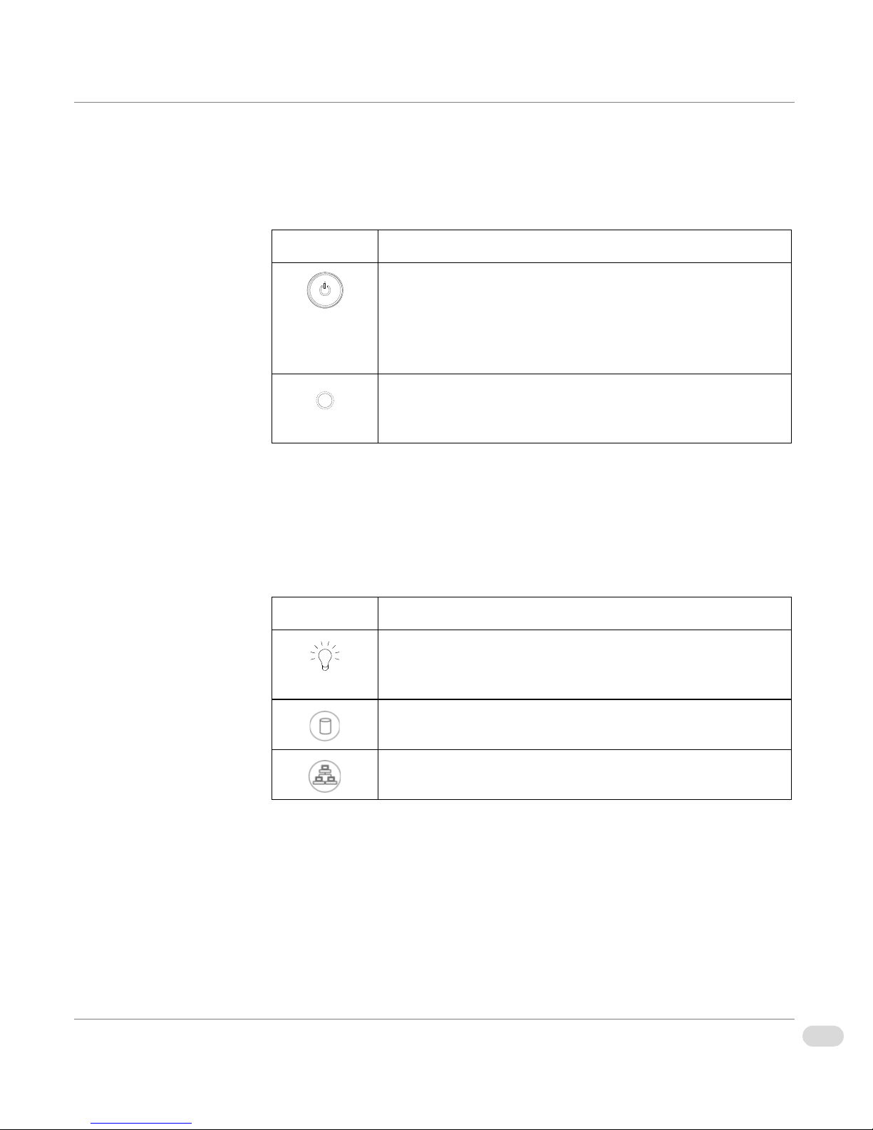
Front Panel Buttons
There are two push-buttons located on the front of the chassis. These are the
power on/off button and the reset button.
Button Description
Power: The main power button is used to apply or remove
power from the power supply to the system. Turning off
system power with this button removes the main power but
keeps standby power supplied to the system. Therefore, you
must unplug system before servicing.
Reset: The reset button is used to reboot the system. A pen
or other small device is required to activate this button and
reset the system.
Front Panel LEDs
The control panel located on the front of the chassis has six LEDs. These LEDs
provide you with critical information related to different parts of the system.
The following table explains what each LED indicates when illuminated and any
corrective action you may need to take.
LED Description
Power: Indicates power is being supplied to the system's
power supply units. This LED should normally be illuminated
when the system is operating.
HDD: Indicates IDE channel activity and SAS2/SATA drive
activity when flashing.
NIC 1: Indicates network activity on GLAN1 when flashing.
Copyright © 2014 Harris Broadcast
Proprietary and Confidential
19Chapter 1 | Chassis Components
G8 Hardware Installation Manual
Page 22
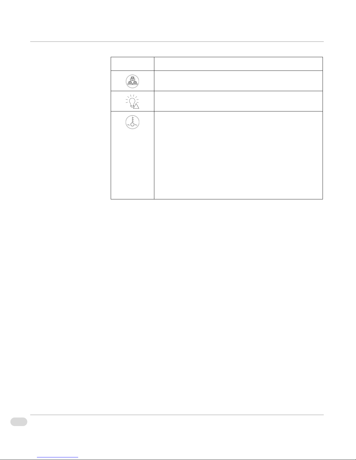
LED Description
!
NIC 2: Indicates network activity on GLAN2 when flashing.
Power Failure: When this LED flashes, it indicates a power
failure in the power supply.
Overheat/Fan Fail: When this LED flashes it indicates a fan
failure. When continuously on (but not flashing) it indicates
an overheat condition, which may be caused by cables
obstructing the airflow in the system or the ambient room
temperature being too warm. Check the routing of the cables
and make sure all fans are present and operating normally.
You should also check to make sure that the chassis covers
are installed properly. Finally, verify that the heatsinks are
also installed properly. This LED will remain flashing or on
as long as the overheat condition exists.
SAS2/SATA LEDs
Each SAS2/SATA drive carrier has two LEDs.
•
Green or Blue: Each hard disk drive carrier has either a green or a blue
LED, depending on the hard disk drives and backplane used. When
illuminated, this LED indicates drive activity. A connection to the SATA
backplane enables this LED to blink on and off when that particular drive is
being accessed.
•
Red: The red LED indicates a SAS2/SATA drive failure. If one of the SAS2/
SATA drives fail, you should be notified by your system management
software.
20 Chapter 1 | Chassis Components
G8 Hardware Installation Manual
Proprietary and Confidential
Copyright © 2014 Harris Broadcast
Page 23
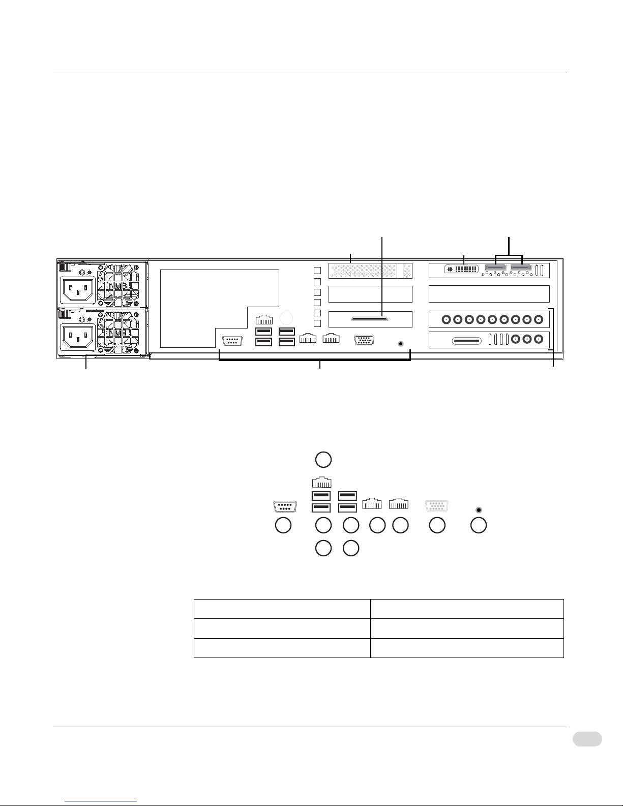
Back Panel
Motherboard I/OPower Supply Modules 1 & 2
GPI/O AB4 (AfterBurner4)
Media Disk Subsystem RAID Controller
GPU/DVI Port
Display Ports 1 & 2
Broadcast I/O
6
109875
4
1 3
2
The following information details the back panel components of the G8 system.
Back Panel
Components
Motherboard I/O
The following image shows the back panel components of the G8 system. Note
that the exact device placement on your system may vary slightly from the
graphic.
Figure 1-4: G8 Back Panel
The following details the motherboard connectors and I/O.
1: COM port 7-8: Gigabit LAN 1 & 2
2: IPMI_LAN * 9: VGA (INACTIVE)
3-6: USB ports 10: UID switch
Copyright © 2014 Harris Broadcast
Figure 1-5. Motherboard I/O
Proprietary and Confidential
21Chapter 1 | Chassis Components
G8 Hardware Installation Manual
Page 24

* For further details on the IPMI functions, see the “IPMI Manual (SMT).pdf”
that is accessible from the following Supermicro web page:
http://www.supermicro.com/support/manuals/
.
G411 Broadcast I/O
The following details the G411 broadcast I/O:
9 8 7 6 5 4
13 12 11 10
Figure 1-6. G411 Broadcast I/O
G411 Video I/O (right to left)
1
: SDI output 1 6: SDI input 3
2: SDI input 1 7: SDI output 4
3: SDI output 2 8: SDI input 4
4: SDI input 2 9: analog reference input
5: SDI output 3
3 2 1
HD BNCs (right to left)
10: SD preview output (UNSUPPORTED)
11: SD preview output (UNSUPPORTED)
12: LTC Timecode input
13: AES audio ponytail cable connector
22 Chapter 1 | Chassis Components
G8 Hardware Installation Manual
Proprietary and Confidential
Copyright © 2014 Harris Broadcast
Page 25

AES Ponytail Cable
The following details the BNC connectors for the AES ponytail cable.
Figure 1-7. AES Ponytail Cable
G411
Specifications
Power Supply
Modules
For G411 technical specifications see:
• “G411 General Specifications” on page 68
• “G411 HD/SDI Video Specifications” on page 69
• “G411 Genlock (Ref In) Specifications” on page 71
There are two power supply modules connected to your system. If there is a
failure with one of the modules, an alarm sounds. It is essential that both power
supply modules be connected at all times, therefore it is recommended that the
failed module be replaced immediately to avoid possible damage to your
system due to loss of power.
Copyright © 2014 Harris Broadcast
Proprietary and Confidential
23Chapter 1 | Chassis Components
G8 Hardware Installation Manual
Page 26

If you need to replace a failed power supply, see “Change the Power Supply” on
page 34 for replacement the procedure.
Table 1-1. Power Supply LED Descriptions
Component Color Condition Description
Power Supply
Modules LED
Green Power Supply DC On
Amber Power Supply Standby
Off No AC Power to the System
Note: For extra insurance against power loss, you may wish to connect the two
power supply modules to AC outlets on different circuit breakers or
connect the system to an Uninterruptible Power Supply (UPS).
24 Chapter 1 | Chassis Components
G8 Hardware Installation Manual
Proprietary and Confidential
Copyright © 2014 Harris Broadcast
Page 27

Chapter 2
Installation and Setup
Page 28

Overview
This chapter provides information about installing your Inscriber G8 system,
and includes the following topics:
• “Chassis Components Installation” on page 27
• “Chassis Rack Installation” on page 36
26 Chapter 2 | Installation and Setu p
G8 Hardware Installation Manual
Proprietary and Confidential
Copyright © 2014 Harris Broadcast
Page 29

Chassis Components Installation
Warning
This section describes important safety guidelines, tools needed for installation, and how to access and
install chassis components.
Important Safety
Guidelines
This product should only be
accessed and serviced by
technically qualified personnel
or technicians.
To avoid personal injury and property damage, please read all the information
provided in “Safety Guidelines” on page 10, and carefully follow all the safety
steps listed in this chapter before accessing or servicing your system or its
components.
Safety Steps
Before accessing the chassis
1 Turn off all peripheral devices and the power supply connected to the
system.
2 Unplug all power cords from the system or wall outlets.
3 Disconnect all the cables and label the cables for easy identification.
4 Use a grounded wrist strap designed to prevent static discharge when
handling components.
Removing the chassis covers
After completing the above steps, you can remove the chassis covers and install
components and devices into the chassis as described in this chapter.
1 Unlock and remove the screws and fasteners to remove the covers or
components.
2 Save all the screws and fasteners for later use. (If necessary, label the
3 Follow the instructions provided in this chapter to remove the chassis
Installation Tools
You will need the following tools for the safe and proper installation of your
system.
• Phillips screw driver
• Anti-static strap
Copyright © 2014 Harris Broadcast
screws and fasteners for easy identification.)
covers.
Proprietary and Confidential
G8 Hardware Installation Manual
27Chapter 2 | Installation and Setup
Page 30

Install Hard Drives
7
The G8 comes equipped with sixteen hot-swappable hard drives. Only SAS2 or
enterprise SATA HDDs are recommended for use in the G8 chassis.
Remove Hard Drive Trays from the Chassis
1 Press the release button on the drive carrier. This extends the drive carrier
handle.
2 Hold the handle to pull the tray out of the chassis.
7
Release button is located on
the bottom of the drive carrier.
Figure 2-1. Tray Removed from Chassis
Install Hard Drive into a Drive Carrier
1 Insert a drive into the carrier with the PCB side facing down and the
connector end toward the rear of the carrier.
2 Align the drive in the carrier so that the mounting holes of both are
aligned. Note that there are holes in the carrier marked "SAS" or “SATA”
to aid in correct installation.
28 Chapter 2 | Installation and Setu p
G8 Hardware Installation Manual
Proprietary and Confidential
Copyright © 2014 Harris Broadcast
Page 31

3 Secure the drive to the carrier with four screws as illustrated. Use the four
M3 flat-head screws included in the HDD bag of your accessory box. Note
that the screws used to secure the dummy drive to the tray cannot be used
to secure the hard drive.
4 Insert the hard drive and drive carrier into its bay vertically, keeping the
carrier oriented so that the release button is on the bottom. When the
carrier reaches the rear of the bay, the release handle will retract.
Copyright © 2014 Harris Broadcast
Figure 2-2. Chassis Drive Tray
Proprietary and Confidential
29Chapter 2 | Installation and Setup
G8 Hardware Installation Manual
Page 32

5 Using the thumb, push against the upper part of the hard drive handle.
Push the hard drive into the hard drive bay as illustrated until the hard
drive clicks into the locked position.
Figure 2-3. Proper Installation of the Hard Drive into the Har d Driv e Bay
30 Chapter 2 | Installation and Setu p
G8 Hardware Installation Manual
Proprietary and Confidential
Copyright © 2014 Harris Broadcast
Page 33

Remove the
Warning
1
1
2
3
Chassis Cover
Except for short periods of
time, do NOT operate the
server without the cover in
place. The chassis cover must
be in place to allow proper
airflow and prevent
overheating.
Before installing any components, replacing chassis fans, or accessing the
motherboard, you first need to remove the top cover.
1 Press both release tabs at the same time to release the cover from the
locked position.
2 Once the top cover has been released, slide the cover backwards, toward
the rear of the chassis.
3 Lift the cover up and off the chassis.
Copyright © 2014 Harris Broadcast
Figure 2-4. Remove Chassis Cover
Proprietary and Confidential
G8 Hardware Installation Manual
31Chapter 2 | Installation and Setup
Page 34

System Fans
Release Tab
There are three fans that provide cooling for the chassis. These fans circulate
air through the chassis as a means of lowering the chassis internal temperature.
The fans are hot-swappable and can be replaced without powering-down the
system.
Replace a System Fan
1 If necessary, open the chassis while the power is running to determine
which fan requires changing.
Note that you should never run the system for an extended period of time
with the chassis open.
2 Press the fan release tab to lift the failed fan from the chassis and pull it
completely out of the chassis.
Figure 2-5. System Fan
3 Place the new fan into the vacant space in the housing while making sure
the arrows on the top of the fan (indicating air direction) point in the same
direction as the arrows on the other fans.
The fan will automatically begin running at the correct speed.
Figure 2-6. Placing the Low Profile System Fan
32 Chapter 2 | Installation and Setu p
G8 Hardware Installation Manual
Proprietary and Confidential
Copyright © 2014 Harris Broadcast
Page 35

Figure 2-7. Placing the UIO System Fan
Replace the
Onboard CR2032
Battery
Power Supply
If you are replacing the onboard battery make sure to handle the used battery
carefully. Do not damage the battery in any way; a damaged battery may release
hazardous materials into the environment. Do not discard a used battery in the
garbage or a public landfill. Please comply with the regulations set up by your
local hazardous waste management agency to dispose of your used battery
properly.
Lithium Battery
Battery Holder
The G8 system has two redundant 720 or 900 Watt power supplies. The power
modules are hot-swappable, enabling the power supplies to be changed without
powering down the system. These power supplies are auto-switching capable.
This enables the power supply to automatically sense and operate at a 100v to
240v input voltage. An amber light will be illuminated on the power supply
when the power is off. An illuminated green light indicates that the power
supply is operating.
Copyright © 2014 Harris Broadcast
Proprietary and Confidential
33Chapter 2 | Installation and Setup
G8 Hardware Installation Manual
Page 36

Warning
Unplug the power cord
Release Tab
before removing the power
supply.
Change the Power Supply
1 Determine which power supply needs to be replaced and unplug the power
cord to that module.
2 Push the release tab (on the back of the power supply) to release the power
module from the chassis.
Figure 2-8. Power Supply Removed
3 Hold down the release tab and pull the power supply out using the handle
provided on the power module.
4 Replace the failed power module with the same model power supply.
5 Push the new power supply module into the power bay until the tab clicks
into the locked position.
6 Plug the AC power cord back into the module and the replacement power
module will automatically power-up.
Install the Power Distributor
The power distributor provides failover and power supply redundancy and is
pre-installed in the chassis. In the rare event that you have to replace the power
distributor, use the following steps.
1 Power-down the system and unplug the power cord from the power
module.
2 Remove all cable connections to the power supply from the motherboard,
backplane, and other components.
3 Remove both power supply modules.
4 Remove the screws securing the power distributor.
5 Gently pull the power distributor from the chassis. Gently guide all the
cables through the power distributor housing.
34 Chapter 2 | Installation and Setu p
G8 Hardware Installation Manual
Proprietary and Confidential
Copyright © 2014 Harris Broadcast
Page 37

6 Slide the new power distributor module into the power distributor housing.
Make sure that you slide the cables through the bottom of the housing.
Figure 2-9. Installing the Power Distributor
7 Reconnect all the power cables, replace the power supply, and insert the
plug into the wall.
Copyright © 2014 Harris Broadcast
Proprietary and Confidential
35Chapter 2 | Installation and Setup
G8 Hardware Installation Manual
Page 38

Chassis Rack Installation
This section provides steps for installing the chassis into the rack unit you are using.
Rack Location
Prepare for Setup
Decide on a suitable location for the rack unit that will hold your chassis. It
should be situated in a clean, dust-free area that is well ventilated. Avoid areas
where heat, electrical noise and electromagnetic fields are generated. The
system needs to be placed near a grounded power outlet. Be sure to read the
precautions in the next section.
The box your chassis was shipped in should include two sets of rail assemblies
and the mounting screws needed for installing the system into the rack. Also
included is an optional square hole to round hole converter bracket, for use in
racks with round mounting holes. Please read this section in its entirety before
you begin the installation procedure outlined in the sections that follow.
Choosing a Setup Location
• Leave enough clearance in front of the rack to enable you to open the front
door completely (~25 inches).
• Leave approximately 30 inches of clearance in the back of the rack to allow
for sufficient airflow and ease in servicing.
• This product is for installation only in a Restricted Access Location
(dedicated equipment rooms, service closets and the like).
Warnings and
Precautions
36 Chapter 2 | Installation and Setu p
G8 Hardware Installation Manual
Rack Precautions
• Ensure that the leveling jacks on the bottom of the rack are fully extended
• In single rack installations, stabilizers should be attached to the rack.
• In multiple rack installations, the racks should be coupled together.
• Always make sure that the rack is stable before extending a component
• You should extend only one component at a time. Extending two or more
General System Precautions
• Review the electrical and general safety precautions that came with the
to the floor with the full weight of the rack resting on them.
from the rack.
simultaneously may cause the rack to become unstable.
components you are adding to your chassis.
Proprietary and Confidential
Copyright © 2014 Harris Broadcast
Page 39

• Determine the placement of each component in the rack before you install
the rails.
• Install the heaviest system components on the bottom of the rack first, and
then work upwards.
• Use a regulating uninterruptible power supply (UPS) to protect the system
from power surges, voltage spikes and to keep your system operating in
case of a power failure.
• Allow the hot plug hard drives and power supply modules to cool before
touching them.
• Always keep the rack's front door and all panels and components on the
system closed when not servicing them to maintain proper cooling.
Rack Mounting
Considerations
Ambient Operating Temperature
If installed in a closed or multi-unit rack assembly, the ambient operating
temperature of the rack environment may be greater than the ambient
temperature of the room. Therefore, consideration should be given to installing
the equipment in an environment compatible with the manufacturer’s maximum
rated ambient temperature (TMRA).
Reduced Airflow
Equipment should be mounted into a rack so that the amount of airflow
required for safe operation is not compromised.
Mechanical Loading
Equipment should be mounted into a rack so that a hazardous condition does
not arise due to uneven mechanical loading.
Circuit Overloading
Consideration should be given to the connection of the equipment to the power
supply circuitry and the effect that any possible overloading of circuits might
have on overcurrent protection and power supply wiring. Appropriate
consideration of equipment nameplate ratings should be used when addressing
this concern.
Copyright © 2014 Harris Broadcast
Proprietary and Confidential
37Chapter 2 | Installation and Setup
G8 Hardware Installation Manual
Page 40

Reliable Ground
Rail Assembly
(with rails extended)
Rail Assembly
(with rails retracted)
outer rail
middle rail
inner rail
This side
faces outward.
locking tab
A reliable ground must be maintained at all times. To ensure this, the rack itself
should be grounded. Particular attention should be given to power supply
connections other than the direct connections to the branch circuit (i.e. the use
of power strips, etc.).
Rack Mounting
This section provides information on installing the chassis into a rack unit with
the rails provided. There are a variety of rack units on the market, which means
that the assembly procedure might differ slightly from the instructions
provided. You should also refer to the installation instructions that came with
the rack unit you are using.
Note: This rail will fit a rack between 26.5" and 36.4" deep.
Identify the Sections of the Rack Rails
The chassis package includes two rail assemblies in the rack mounting kit. Each
assembly consists of three sections: an inner chassis rail which secures directly
to the chassis, an outer rail that secures to the rack, and a middle rail which
extends from the outer rail. These assemblies are specifically designed for the
left and right side of the chassis.
Lock Tabs
Each inner rail has a locking tab. This tab locks the chassis into place when
installed and pushed fully into the rack. These tabs also lock the chassis in
place when fully extended from the rack. This prevents the system from coming
38 Chapter 2 | Installation and Setu p
G8 Hardware Installation Manual
completely out of the rack when the chassis is pulled out for servicing.
Figure 2-10. Left Rail Assembly
Proprietary and Confidential
Copyright © 2014 Harris Broadcast
Page 41

Release the Inner Rail from the Outer Rails
Press locking tab down.
inner rail released
1 Identify the left and right outer rail assemblies.
2 Pull the inner rail out of the outer rail until it is fully extended.
3 Press the locking tab down to release the inner rail.
Figure 2-11. Release Inner Rail
4 Repeat steps 1-3 for the second outer rail.
Install the Inner Rails on the Chassis
1 Confirm that the left and right inner rails have been correctly identified.
2 Place the inner rail firmly against the side of the chassis, aligning the hooks
on the side of the chassis with the holes in the inner rail.
3 Slide the inner rail forward toward the front of the chassis until the rail
clicks into the locked position, which secures the inner rail to the chassis.
Copyright © 2014 Harris Broadcast
Proprietary and Confidential
39Chapter 2 | Installation and Setup
G8 Hardware Installation Manual
Page 42

4 Secure the inner rail to the chassis with the screws provided.
inner rails
Figure 2-12. Secure Inner Rails to Chassis
5 Repeat steps 2 - 4 for the second inner rail.
40 Chapter 2 | Installation and Setu p
G8 Hardware Installation Manual
Figure 2-13. Inner Rails Installed
Proprietary and Confidential
Copyright © 2014 Harris Broadcast
Page 43

Install the Outer Rails on the Rack
1 Press upward on the locking tab at the rear end of the middle rail.
Figure 2-14. Locking Tab
2 Push the middle rail back into the outer rail.
3 Hang the hooks of the front of the outer rail onto the slots on the front of
the rack. If necessary, use screws to secure the outer rails to the rack.
Figure 2-15. Secure Outer Rails
4 Pull out the rear of the outer rail, adjusting the length until it fits within the
posts of the rack.
5 Hang the hooks of the rear portion of the outer rail onto the slots on the
rear of the rack. If necessary, use screws to secure the rear of the outer rail
to the rear of the rack.
Copyright © 2014 Harris Broadcast
Proprietary and Confidential
41Chapter 2 | Installation and Setup
G8 Hardware Installation Manual
Page 44

6 Repeat steps 1 - 5 for the second outer rail.
ball-bearing shuttle
Figure 2-16. Outer Rail Installed
St andard Chassis
Installation
1 Confirm that the inner rails are properly installed on the chassis.
2 Confirm that the outer rails are correctly installed on the rack.
3 Pull the middle rail out from the front of the outer rail and make sure that
the ball-bearing shuttle is at the front locking position of the middle rail.
4 Align the chassis inner rails with the front of the middle rails.
42 Chapter 2 | Installation and Setu p
G8 Hardware Installation Manual
Figure 2-17. Align Chassis Inner Rails to Middle Rails
Proprietary and Confidential
Copyright © 2014 Harris Broadcast
Page 45

5 Slide the inner rails on the chassis into the middle rails, keeping the
pressure even on both sides, until the locking tab of the inner rail clicks
into the front of the middle rail, locking the chassis into the fully extended
position.
6 Depress the locking tabs of both sides at the same time and push the
chassis all the way into the rear of the rack.
7 If necessary for security purposes, use screws to secure the chassis handles
to the front of the rack.
Copyright © 2014 Harris Broadcast
Figure 2-18. Chassis Installed in Rack
Proprietary and Confidential
G8 Hardware Installation Manual
43Chapter 2 | Installation and Setup
Page 46

BIOS Error Beep Codes
During the POST (Power-On Self-Test) routines, which are performed each time the system is powered on,
errors may occur.
Non-Fatal and
Fatal Errors
Non-fatal errors are those which, in most cases, allow the system to continue
the boot-up process. The error messages normally appear on the screen.
Fatal errors are those which will not allow the system to continue the boot-up
procedure. If a fatal error occurs, you should consult with your system
manufacturer for possible repairs.
These fatal errors are usually communicated through a series of audible beeps.
The numbers on the fatal error list correspond to the number of beeps for the
corresponding error. All errors listed, with the exception of Beep Code 8, are
fatal errors.
Table 2-1. BIOS Error Beep Codes
Beep Code Error Message Description
1 beep Refresh Circuits have been reset (Ready to
power up)
5 short beeps and
Memory error No memory detected in the system
1 long beep
5 beeps No Con-In or
Conout devices
Con-In includes USB or PS/2
keyboard, PCi or Serial console
redirection, IPMI KVM or SOL.
Con-Out includes video controller,
PCI or Serial console redirection or
IPMI SOL.
1 Continuous
beep
44 Chapter 2 | Installation and Setu p
G8 Hardware Installation Manual
System OH System Overheat
Proprietary and Confidential
Copyright © 2014 Harris Broadcast
Page 47

Chapter 3
Setup and Configuration
Page 48

Overview
This chapter provides information about configuring your G8 system, and
includes the following topics:
• “Disk Subsystems” on page 47
• “GPI/AfterBurner 4” on page 49
• “Preview Display” on page 53
46 Chapter 3 | Setup and Configuration
G8 Hardware Installation Manual
Proprietary and Confidential
Copyright © 2014 Harris Broadcast
Page 49

Disk Subsystems
This section details the G8 disk subsystems.
Disk Subsystems
Organization
Operating drives 0 and 1 are set up in a RAID 1 mirror configuration. This
configuration consists of 2 x 250 GB SATA II drives with the addition of eight
250 GB SATA media drives in RAID 5 linked together for a total drive capacity
of approximately 1.7 TB.
The G8 disk subsystems features:
• RAID 1 for system boot drive
• RAID 5 for media storage
• 100 MB data rate for system drive
• 400 MB data rate for media drive
• System and media storage on separate spindles
• 2 x 250 GB SATA system drives
• 8 x 250 GB SATA media drives
• 1.7 TB approximate total media drive capacity
Spare Drive Bays
Drives:
Media Disk Subsystem: RAID 5
8 9 10 11 12 13 14 150 1 2 3 4 5 6 7
Drive
Configuration
Copyright © 2014 Harris Broadcast
The G8 system uses mirror (RAID 1) drives. If one drive fails, the other drive
can continue operations while you replace the failed drive. For details on
Empty Drive Bays (potential drive storage)
System Drives: RAID 1 (Mirror)
Figure 3-1. Front Panel: Disk Subsystems
Proprietary and Confidential
G8 Hardware Installation Manual
47Chapter 3 | Setup and Configuration
Page 50

replacing a hard drive see “Install Hard Drives” on page 28.
3
2
7
6
5
4
15149810 1312111010
RAID 1
250 GB
RAID 5
1.7 TB
250 GB x 8250 GB x 2
Disks 8 -15
D:\
Disks 0,1
C:\
1.7 TB250 GB
Figure 3-2. Drive Configuration
48 Chapter 3 | Setup and Configuration
G8 Hardware Installation Manual
Proprietary and Confidential
Copyright © 2014 Harris Broadcast
Page 51

GPI/AfterBurner 4
VHDCI
Pin
Port
Signal
RJ
Pin
RJ-11
#
(Label)
RJ
Pin
VHDCI
Pin
Port
Signal
1 GND
NC
NC
35 GND
2 1 TX+ → 1
1
(A)
2 ← 36 1 TX-
3 1 RX+ ← 4
3 → 37 1 RX-
4 2 TX+ → 1
2
(B)
2 ← 38 2 TX-
5 2 RX+ ← 4
3 → 39 2 RX- 6 3
TX+ → 1
3
(C)
2 ← 40 3 TX-
7 3 RX+ ← 4
3 → 41 3 RX-
8 4 TX+ → 1
4
(D)
2 ← 42 4 TX-
9 4 RX+ ← 4
3 → 43 4 RX-
10 5 TX+ → 1
5
(E)
2 ← 44 5 TX-
11 5 RX+ ← 4
3 → 45 5 RX-
12 6 TX+ → 1
6
(F)
2 ← 46 6 TX-
13 6 RX+ ← 4
3 → 47 6 RX-
14 7 TX+ → 1
7
(G)
2 ← 48 7 TX-
15 7 RX+ ← 4
3 → 49 7 RX-
16 8 TX+ → 1
8
(H)
2 ← 50 8 TX-
17 8 RX+ ← 4
3 → 51 8 RX-
18 9 GPO1
→
1
9
(J)
2 ← 52 9 GPO1
19 9 GPI1
←
4
3 → 53 9 GND
20
10
GPO2
→
1
10
(K)
2 ← 54
10
GP02
21
10
GPI2
←
4
3 → 55
10
GND
22
11
GPO3
→
1
11
(L)
2 ← 56
11
GPO3
23
11
GPI3
←
4
3 → 57
11
GND
24
12
GPO4
→
1
12
(M)
2 ← 58
12
GPO4
25
12
GPI4
←
4
3 → 59
12
GND
26
13
GPO5
→
1
13
(N)
2 ← 60
13
GPO5
27
13
GPI5
←
4
3 → 61
13
GND
28
14
GPO6
→
1
14
(P)
2 ← 62
14
GPO6
29
14
GPI6
←
4
3 → 63
14
GND
30
15
GPO7
→
1
15
(Q)
2 ← 64
15
GPO7
31
15
GPI7
←
4
3 → 65
15
GND
32
16
GPO8
→
1
16
(R)
2 ← 66
16
GPO8
33
16
GPI8
←
4
3 → 67
16
GND
34 GND
NC NC
68 GND
G8 systems currently support eight GPIO on the AfterBurner4 (AB4) via the orderable fanout cable (Harris
Broadcast part number:
INSG8AB7 or INSG8AB16).
Fanout Cable
Pinouts (AB4 to
RJ12)
Note that the RS422 ports (labels A - H) are not currently supported and are
reserved for future expansion.
Copyright © 2014 Harris Broadcast
Proprietary and Confidential
49Chapter 3 | Setup and Configuration
G8 Hardware Installation Manual
Page 52

AB4 Cabling
Currently not supported.
Reserved for future expansion.
Using Fanout
Cables
Instead of the individual RJ cables for each port, a single "fanout" cable is
available for each serial 16 card. This cable allows a single VHDCI connection
to the board, while providing 16 individual RJ connections. Eight connections
are currently supported (labeled J - N and P - R) while eight connections are
reserved for future expansion (labeled A - H).
The design of the cables allows this single VHDCI connection to the board to
be accomplished without splices within the length of the cable. This approach
greatly reduces the number of cables, simplifies the installation, connection,
labeling, and dressing of cables, and improves the overall cabling to the
chassis.
50 Chapter 3 | Setup and Configuration
G8 Hardware Installation Manual
Figure 3-3. Fanout Cable
Proprietary and Confidential
Copyright © 2014 Harris Broadcast
Page 53

Fanout Cable Lengths
The standard cable is 7 ft (210 cm) in total length, with a 3 ft (90 cm) portion,
a single cable from the VHDCI connector carrying all 16 ports, and the
remaining 4 ft (120 cm) individual cables for each port (Harris Broadcast part
number:
part number:
INSG8AB7). A 16 ft (485 cm) cable is also available (Harris Broadcast
INSG8AB16).
INSG8AB16INSG8AB7
Copyright © 2014 Harris Broadcast
Figure 3-4. Available Fanout Cable Lengths
Proprietary and Confidential
G8 Hardware Installation Manual
51Chapter 3 | Setup and Configuration
Page 54

Pinout Reference
2
1
3
4
NO
GPI - OUTPUT CIRCUIT
OMRON G3VM-21LR1
GPI - INPUT CIRCUIT
MOCD207/SO
4
3
2
1
5
6
7
8
5V
51OR
51OR
AB4 RJ12 GPI PINOUT
RJ12
1GPI-O
2GPI-I
3GPI-IGND
4GPI-O
5nc
6nc
52 Chapter 3 | Setup and Configuration
G8 Hardware Installation Manual
Proprietary and Confidential
Copyright © 2014 Harris Broadcast
Page 55

Preview Display
Before you start using the G-Scribe software application, you should set up your preview display. The
available preview options depend on your system setup.
Preview Display
Setup
1 With the G8 system shut down, connect the second monitor to the DVI
port on the back of the system.
2 Reboot the system.
3 When the system has restarted, right-click on the Windows desktop.
4 Select NVIDIA Control Panel from the right-click menu.
Figure 3-5. Select NVIDIA Control Panel
5 In the NVIDIA Control Panel, click the “Set up multiple displays” link
included with the Display options on the left. The options for multiple
displays appear on the right.
6 In the first step, select the “Configured independently from each other
Copyright © 2014 Harris Broadcast
Figure 3-6. NVIDIA Control Panel - Multiple Display Options
(Dual View)” option.
Proprietary and Confidential
G8 Hardware Installation Manual
53Chapter 3 | Setup and Configuration
Page 56

7 In the second step, confirm your display monitors are selected from the
drop-down list.
8 In the third step, confirm the display you are using for G8 operations is
selected from the drop-down list. The second display is then used for the
VGA preview.
9 Click Apply to apply the preview settings.
54 Chapter 3 | Setup and Configuration
G8 Hardware Installation Manual
Proprietary and Confidential
Copyright © 2014 Harris Broadcast
Page 57

Chapter 4
Maintenance
Page 58

Overview
This chapter provides information about maintaining your G8 system, and
includes the following topics:
• “Hot Swap Power Supplies” on page 57
• “System Restore” on page 58
• “Prevent Damage and Malfunction” on page 63
56 Chapter 4 | Maintenance
G8 Hardware Installation Manual
Proprietary and Confidential
Copyright © 2014 Harris Broadcast
Page 59

Hot Swap Power Supplies
Your system uses a dual-redundant hot-swappable power supply. You can
replace a failed power supply module without turning the system off.
Make sure you have a replacement power supply before starting this procedure.
Keep a replacement power supply module on hand, and replace failed modules
promptly. Running on one power supply module for any length of time can
compromise the uninterrupted operation of your system.
Three signals indicate that a power supply module has failed.
• The warning alarm sounds.
• The green LED on the failed power supply module is off.
• The PS FAIL LED on the front of the unit is red.
To stop the alarm from sounding, unplug the power supply module from the
system.
Note: For redundant operation your system requires two working modules. If
one module fails, replace the failed module immediately.
To replace the
failed power
supply module
1 Put on protective gloves before removing the failed power supply module.
The power supply module is very hot.
2 Pull out the failed power supply module, and put it somewhere where it
will not be touched until it cools down.
3 Insert a replacement power supply module.
4 Confirm that the power supply module LED is green.
5 Confirm that the PS FAIL LED on the front of the unit is off.
6 Snap the power supply module in place.
See “Change the Power Supply” on page 34 for details on replacing a power
supply module.
Copyright © 2014 Harris Broadcast
Proprietary and Confidential
57Chapter 4 | Maintenance
G8 Hardware Installation Manual
Page 60

System Restore
Create a Restore
Point
A factory system restore image is available on your system’s D:\Recovery
folder. This folder is protected from accidental deletion. Do not attempt to
change the protection settings of the folder or attempt to delete it.
To perform system recovery or custom image creation tasks, use the System
Restore flash drive that was shipped in your accessory box with the system. You
may wish to create an additional “production” system restore image after you
have fully configured/administered your system.
1 Follow these steps to change the system’s Hard Disk Drive and Boot
Device Priority so that the System Restore flash drive is the first device.
a Unplug all USB devices from the system.
b Attach the System Restore flash drive to one of the USB ports on the
system.
You may use a different flash drive to store your restore point if you
wish. This might be necessary if your restore point is too large to fit on
the System Restore flash drive.
c Power on the system.
d As the system boots, during the POST cycle, press
F11 to access the
BBS (Boot Block Selection) menu.
58 Chapter 4 | Maintenance
G8 Hardware Installation Manual
e Move the cursor down to the
USB Disk option and hit Enter.
2 Windows loads, followed by the Windows Preinstallation Environment.
This process may take several minutes.
Proprietary and Confidential
Copyright © 2014 Harris Broadcast
Page 61

3 The Harris Broadcast System Recovery screen appears.
Figure 4-1. Harris Broadcast System Recovery Screen
System Restore
4 Click the Advanced Options button. The Advanced Options menu appears.
5 Click the Manual Recovery button to allow manual image creation and
recovery.
6 Ghost launches. Use the Ghost application to choose a source and a target
for your restore point.
Note: Loss of data is possible if you incorrectly specify your target. Be
sure of your settings before you continue.
7 Within Ghost, create the image.
8 After the image creation is complete, shut down your system so the power
is off.
9 Remove the flash drive which contains your new restore point and store it
in a safe place.
10 Reattach any USB devices that you removed before starting this procedure.
11 Power on your system.
1 Follow these steps to change the system’s Hard Disk Drive and Boot
Device Priority so that the System Restore flash drive is the first device.
a Unplug all USB devices from the system.
Copyright © 2014 Harris Broadcast
Proprietary and Confidential
59Chapter 4 | Maintenance
G8 Hardware Installation Manual
Page 62

b Attach the System Restore flash drive to one of the USB ports on the
system.
c Power on the system.
d As the system boots, during the POST cycle, press
F11 to access the
BBS (Boot Block Selection) menu.
e Move the cursor down to the
USB Disk option and hit Enter.
2 Windows loads, followed by the Windows Preinstallation Environment.
This process may take several minutes.
3 The Harris Broadcast System Recovery screen appears.
60 Chapter 4 | Maintenance
G8 Hardware Installation Manual
Figure 4-2. Harris Broadcast System Recovery Screen
•
Follow these steps to restore your system to a restore point that you
have created previously.
a Click the Advanced Options button. The Advanced Options menu
appears.
b Click the Manual Recovery button to allow manual image creation
and recovery.
c The Ghost application launches. Select the recovery source you
wish to use and the target of the recovery.
Note: Loss of data is possible if you incorrectly specify your
target. Be sure of your settings before you continue.
Proprietary and Confidential
Copyright © 2014 Harris Broadcast
Page 63

d Wait for the recovery process to finish.
• Follow these steps to automatically restore your system to its factory
settings.
a Click the Recover System button.
b When the factory recovery data is found, you are prompted to
continue.
Figure 4-3. System Recovery Prompt
c If you are certain that you want to recover your system, click the
OK button.
d The Ghost application launches and the restore procedure begins.
4 After the restore is complete, click the Reboot Now button to restart your
Copyright © 2014 Harris Broadcast
system.
Figure 4-4. Restore Progress Indicator
Proprietary and Confidential
G8 Hardware Installation Manual
61Chapter 4 | Maintenance
Page 64

5 If you are prompted to reactivate Windows, use your Windows License key
to reactivate the operating system. Refer to the Harris Broadcast System
Note for details on your Windows license.
6 Reattach any USB devices that you removed before starting this procedure.
7 Install any product updates you have received for products that are newer
than your restore point. You can download updates at
http://harrisbroadcast.com/support.
If the system is not fully operational when the restore is complete, verify that
you did not make any incompatible hardware changes.
62 Chapter 4 | Maintenance
G8 Hardware Installation Manual
Proprietary and Confidential
Copyright © 2014 Harris Broadcast
Page 65

Prevent Damage and Malfunction
Read and observe all instructions in this section to keep your system working safely and effectively.
Hardware
Anti-Virus
Software
Do NOT modify the hardware. Your system is delivered with all the necessary
hardware and software already installed. You should not have to open the
system case. However, if the system case is damaged, refer to “Chassis
Components Installation” on page 27 for proper instructions on accessing the
chassis components. Installing additional hardware or modifying the hardware
in any way can compromise the operation of your system.
Harris Broadcast does not condone the operation of anti-virus software on
Graphics systems during operation of the software.
Harris Broadcast supports regular manual or scheduled scans on Graphics
systems, using licensed professional third party applications, during known
off-line time periods when the software is not on-air or actively in use. Under
these conditions, Harris Broadcast agrees that such scans may be conducted
while software applications are running but are not performing editing,
playback, output, or other productive operations. Always disable "scan on
access" options of your anti-virus software.
Any application or service which consumes system resources (including but not
limited to system hard drive access, CPU cycles, and RAM or primary system
bus traffic) will negatively impact the performance and operational status of the
software. Such conditions may impair your Graphics system from meeting its
operational requirements.
Operating System
Updates
Copyright © 2014 Harris Broadcast
To assure the operation, service, technical support, and maintenance of Harris
Broadcast Graphics systems on known tested and qualified operating system
configurations, customers should not install any operating system updates on
Graphics systems unless formally notified by Harris Broadcast to do so. Harris
Broadcast tests and verifies software releases using current updates
immediately prior to release, and are confident of the operation of the updates
as of that date.
Customers who do install additional operating system updates on Graphics
systems waive the right for Harris Broadcast support to assist with any updates
which have not been formally approved by Harris Broadcast. Furthermore,
Harris Broadcast service representatives may require the removal of any
operating system updates which have not been formally approved by Harris
Proprietary and Confidential
63Chapter 4 | Maintenance
G8 Hardware Installation Manual
Page 66

Broadcast for use on Graphics systems, before offering assistance with
troubleshooting and providing service, technical support, or maintenance. If
additional updates have been installed we recommend creating a system restore
point before proceeding.
Automatic
Updates
Harris Broadcast builds and ships Graphics systems with the Microsoft®
Updates feature turned off. This prevents future operating system updates from
automatically installing code which may prevent Harris Broadcast Graphics
systems from operating as expected.
G8 systems are built on a Windows 7® 64-bit platform and, as such, comply
with the platform design rules as they existed when the software was built.
Harris Broadcast has no control over Microsoft’s platform support or the
patches which Microsoft may issue. Harris Broadcast also has no control over
the user-configured distribution mechanism which Microsoft uses to push
updates to machines running operating system software.
64 Chapter 4 | Maintenance
G8 Hardware Installation Manual
Proprietary and Confidential
Copyright © 2014 Harris Broadcast
Page 67

Chapter 5
Specifications
Page 68

Overview
This chapter provides your G8 system specifications, and includes the
following topics:
• “System Technical Specifications” on page 67
• “G411 General Specifications” on page 68
• “G411 HD/SDI Video Specifications” on page 69
• “G411 AES Audio Specifications” on page 70
• “G411 Genlock (Ref In) Specifications” on page 71
• “Power Supply Specifications” on page 72
66 Chapter 5 | Specifications
G8 Hardware Installation Manual
Proprietary and Confidential
Copyright © 2014 Harris Broadcast
Page 69

Specifications
System Technica l Specific ations
The following information details your G8 system’s technical specifications.
Table 5-1. System Technical S pecification
Item Specification
Chassis • 2 RU rack mount
Mouse • Optical USB mouse
Keyboard • USB 104-key system
Network • Two Gigabit Ethernet ports via RJ-45
Serial Ports • RS-232 serial port via DB-9 connector
• Rack rails included
• Dimensions:
Width 17.2" (437mm)
Height 3.5" (89mm)
Depth 24.8" (630mm)
USB Ports • Five USB 2.0 ports
Optical Drive • CD/DVD-RW drive for backup
Power Supply • 2 (1+1) redundant hot swappable power supply
•2 x 740 W
Cooling • High CFM cooling for 24/7 operation
CPU • 2x Intel E5-2620 2 GHz (six core)
RAM • 8 x 2 GB DDR 1333 MHz
Disk
Subsystem
System
Restore
• 2 x 250 GB system drives in RAID 1
• 8 x 250 GB media drives in RAID 5
• Bootable restore USB thumbdrive to return system to
factory configuration
GPU • Nvidia Quadro 4000
Copyright © 2014 Harris Broadcast
Proprietary and Confidential
67Chapter 5 | Specifications
G8 Hardware Installation Manual
Page 70

G411 General Specifications
The following table details the common features of the G411.
Table 5-2. G411 Common Features
Item Specification
HD/SDI Inputs • 4
HD/SDI Outputs • 4
HD/SDI Embedded
•4 x 16
Audio In
HD/SDI Embedded
•4 x 16
Audio Out
Video Formats • 10-bit Uncompressed, 8-bit Uncompressed
• 10-bit Compressed, 8-bit Compressed
Audio Formats • PCM (32-bit, 48k)
Audio Mixer • 128 x 64 track
HD Formats • 1080i, 720p
HD Scan Rates (fps) • 60, 59.94, 50, 30 29.97, 25
LTV Playback • 4 Video + 4 Alpha
LTV Capture • 2 Video or 1 Video + 1 Alpha
HD 2D DVE (10-bit) • 4
HD 3D DVE
•2
(optional)
HD Graphics
• 4 YUV+A (foreground and key)
Framestores
SD Formats • NTSC, PAL
SD Scan Rates (fps) • 60, 59.97, 50
SD Playback • 4 Video + 4 Alpha
SD Capture • 2 Video or 1 Video + 1 Alpha
SD 2D DVE (10 bit) • 4
SD 3D DVE (optional) • 2
SD Graphics
Framestores
Proxy Scaler (realtime
downscaler)
68 Chapter 5 | Specifications
G8 Hardware Installation Manual
• 4 YUV+A (foreground and key)
•1
Proprietary and Confidential
Copyright © 2014 Harris Broadcast
Page 71

Table 5-2. G411 Common Features (Continued)
Item Specification
Video Mixer (wipe/
dissolve effects)
Keyer • 8
Internal Routing • Flexible Crosspoint Mixing Fabric
Down Converter • 2 (Video + Alpha)
Full Size PCI Express
Gen 2 Card
LTC Input • HDBNC, 0.4Vpp to 5Vpp, Hi-Z termination
G411 HD/SDI Video Specifications
The following table outlines the video specifications for the G411.
Table 5-3. HD/SDI Video Specifications
Item Specification
Line/frame rates
supported
Standards • SMPTE424M, SMPTE 292M, SMPTE 259M-C,
•2
•8 lane
• 1080i/60, 1080i/59.94, 1080i/50
• 720p/60, 720p/59.94, 720p/50
• SD-525, 4:3/16:9
•SD-625, 4:3/16:9
——
Note: 1080p is not supported but the system is 1080p capable
for future-proofing.
SMPTE 274M, SMPTE 240M, SMPTE 272M
Input Impedance • 75 Ohms
Input Quantity &
Connector
Input Return Loss • > 15dB, minimum over a frequency range of 5MHz
Input Equalization • Automatic, adjustment-free cable equalization
Input Sensitivity • <100mV
Input Cable length • For HD 135m min.; for SD 250m min. of Belden
Output Impedance • 75 Ohms
Copyright © 2014 Harris Broadcast
•4 HDBNC
to 1.5GHz
1694A cable
Proprietary and Confidential
69Chapter 5 | Specifications
G8 Hardware Installation Manual
Page 72

Table 5-3. HD/SDI Video Specifications (Continued)
Item Specification
Output Quantity /
Connector
Output Return Loss • > 15dB, minimum over a frequency range of 5MHz
Output Signal Level • 800 mV ±10%
Output D.C. Offset • 0.0 V + 0.5 V
Output Rise and Fall
Time
Output Overshoot • <10%
Output Jitter • < 135ps peak-to-peak for HD
Miscellaneous • EDH insertion on output
VITC Input / Output • Supported on HDSDI inputs and outputs
G411 AES Audio Specifications
•4 HDBNC
——
Note: The 2 SD preview outputs are not supported but have
been included for future-proofing.
to 1.5GHz
• < 270ps (20 to 80% amplitude), not differing by
100ps for HD, between 400 to 700ps (20 to 80%
amplitude) for SD
• < 0.2 UI (740ps) peak-to-peak for SD
70 Chapter 5 | Specifications
G8 Hardware Installation Manual
The following table details the AES audio specifications.
Table 5-4. AES Audio Specifications
Item Specification
Standard • AES3-1992, AES 3id-1995, EIAJ CP-340, SMPTE276M
Input Quantity /
Connector
• 1xMDR36 (shared with output) with 8 BNC connectors
via pony tail breakout cable
Sample Resolution • 16/20/24-bit
Input Sampling
• 32kHz, 44.1kHz, 48 kHz, 96kHz
Rates
Input Impedance • 75 Ohms
Input Return Loss • > 40dB, typical from 0.1Hz to 6.0MHz
• > 30dB, worst case from 0.1Hz to 6.0MHz
Input Sensitivity • 120mVpp to 2.5Vpp
Proprietary and Confidential
Copyright © 2014 Harris Broadcast
Page 73

Table 5-4. AES Audio Specifications (Continued)
Item Specification
Maximum Input
•2.5Vpp
Signal
Rise / Fall Time • 5 to 30ns (10% to 90%)
Output Common
• >30dB below output signal (0 to 6MHz)
Mode Component
Output Sampling
•48 kHz
Rate
Output Quantity /
Connector
• 1xMDR36 (shared with input) with 8 BNC connectors
via pony tail breakout cable
Output Coupling • AC Coupled
Output Impedance • 75 Ohms
Output Return Loss • > 40dB, typical from 0.1 Hz to 6.0 MHz
• > 30dB, worst case from 0.1 Hz to 6.0 MHz
Output Level • 1.0V +/-10% (terminated)
Output Jitter • < 0.025UI
Output Rise / Fall
• 5 to 30ns (10% to 90%)
Time
G411 Genl oc k (Ref In) Specifications
The following table details the genlock (reference in) specifications.
Table 5-5. Genlock (Ref In) Specifications
Item Specification
Standard • SMPTE-318M
Input Quantity /
Connector
Input Sensitivity • > 100 mV
Input Impedance • 75Ω or High-Z (software controlled)
Input Return Loss • > 35 dB (25 Hz to 10 mHz)
CMRR • >60dB @60Hz for a 10Vpp input signal
Input Types • NTSC/PAL Color black or 2 V sync or Tri-level sync
Copyright © 2014 Harris Broadcast
Proprietary and Confidential
•1 HDBNC
71Chapter 5 | Specifications
G8 Hardware Installation Manual
Page 74

Power Supply Specifications
The following table outlines the power supply specifications.
Table 5-6. Power Supply Specification
Power Supply 740 W
AC input • 100 - 240V
Nominal DC outputs
+5V standby • 4 Amp
+12 V • 61.7 Amp
•60 - 50Hz
•10 - 3.5 Amp
72 Chapter 5 | Specifications
G8 Hardware Installation Manual
Proprietary and Confidential
Copyright © 2014 Harris Broadcast
Page 75

Index
A
AB4 ................................................................49
AES audio specifications ...............................70
AfterBurner 4 .................................................49
alarms
power supply .............................................23
anti-virus software ..........................................63
B
back panels connectors .................................21
C
chassis rack mount ........................................36
D
damage prevention ........................................63
disk subsystems ............................................47
drive configuration .........................................47
E
electrical safety guidelines .............................10
ESD safety guidelines ....................................11
G
G411 general specifications ..........................68
genlock
specifications .............................................71
GPI .................................................................49
H
HD/SDI video specifications ..........................69
HDD LED .......................................................19
hot swap power supplies ...............................57
I
install
chassis in rack ...........................................36
L
LEDs
front panel ..................................................19
SAS/SATA .................................................20
LEDs and descriptions
front panel ..................................................18
power supply .............................................24
F
front panel ................................................17–19
Front Panel buttons .......................................19
Front Panel LEDs ..........................................19
Copyright © 2014 Harris Broadcast
M
malfunction protection ....................................63
Microsoft updates ..........................................63
Proprietary and Confidential
73Index
G8 Hardware Installation Manual
Page 76

N
S
NIC 1 LED ......................................................19
NIC 2 LED ......................................................20
O
operating system updates ..............................63
Overhead/Fan Fail LED .................................20
P
PC connectors panel .....................................23
Power button ..................................................19
Power Failure LED .........................................20
Power LED .....................................................19
power supply
alarm ..........................................................23
hot swap ....................................................57
replacement ...............................................57
specifications .............................................72
preview display setup ....................................53
R
rack mounting ................................................36
reference in
specifications .............................................71
replace a failed power supply ........................57
Reset button ..................................................19
safety
guidelines ............................................10–13
standards and compliances .........................8
SAS/SATA LEDs ...........................................20
specifications
AES audio ..................................................70
G411 general specs ..................................68
genlock ......................................................71
HD/SDI video .............................................69
power supply .............................................72
system .......................................................67
system
restore .......................................................58
specifications .............................................67
system drive configuration .............................47
U
unpacking ........................................................7
V
VGA preview display ......................................53
video specifications ........................................69
virus scan .......................................................63
W
Windows Automatic Updates .........................63
74 Index
G8 Hardware Installation Manual
Proprietary and Confidential
Copyright © 2014 Harris Broadcast
 Loading...