

Page 1

Rhein Tech Laboratories, Inc. Client: M/A-Com, Inc.
360 Herndon Parkway Model: MultiLink Station
Suite 1400 Standards: FCC Part 90/IC RSS-111
Herndon, VA 20170 ID’s: BV8MLINK/3670A-MLINK
http://www.rheintech.com
Report Number: 2008219
Appendix K: Manual
Please refer to the following pages.
100 of 111
Page 2

Installation and Configuration Manual
MM-014720-001
Rev. A, Mar/09
VIDA Broadband Equipment
Page 3
MM-014720-001, Rev. A
MANUAL REVISION HISTORY
REV DATE REASON FOR CHANGE
- Jul/08 Initial release.
A Mar/09 Added the MultiLink, B510 BS information, approved antenna options, and instructions
for using the base station Web page.
CREDITS
Andrew is a registered trademark of CommScope, Inc.
IndigoVision is a trademark of IndigoVision Group plc.
Windows is a registered trademark of Microsoft Corporation.
Conxall and Multi-Con-X are registered trademarks of Conxall Inc.
Band-it is a registered trademark of BAND-IT-IDEX, Inc., a unit of IDEX Corporation.
All other brand and product names are trademarks, registered trademarks, or service marks of their respective holders.
NOTICE!
The technology embodied in this product is protected by various intellectual property rights including patent rights,
copyrights, and trade secrets of Tyco Electronics Corporation and its suppliers. All Software provided is licensed not sold
and any user of this software and/or technology must execute and comply with the Software License Agreement provided by
Tyco Electronics, governing the use and restrictions on same. User is expressly prohibited from attempting to decompile,
reverse engineer, or disassemble any object code provided, or in any other way convert such object code into humanreadable form. User agrees to comply with all restrictions set forth in the license agreement and to use software only for the
purposes provided.
This product conforms to the European Union WEEE Directive 2002/96/EC. Do not dispose of this product
in a public landfill. Take it to a recycling center at the end of its life.
The software contained in this device is copyrighted by M/A-COM, Inc. Unpublished rights are reserved under the
copyright laws of the United States.
This manual covers M/A-COM, Inc., products manufactured and sold by M/A-COM, Inc.
Repairs to this equipment should be made only by an authorized service technician or facility designated by the supplier.
Any repairs, alterations or substitutions of recommended parts made by the user to this equipment not approved by the
manufacturer could void the user's authority to operate the equipment in addition to the manufacturer's warranty.
This manual is published by M/A-COM, Inc., without any warranty. Improvements and changes to this manual necessitated by typographical errors,
inaccuracies of current information, or improvements to programs and/or equipment, may be made by M/A-COM, Inc., at any time and without notice.
Such changes will be incorporated into new editions of this manual. No part of this manual may be reproduced or transmitted in any form or by any means,
electronic or mechanical, including photocopying and recording, for any purpose, without the express written permission of M/A-COM, Inc.
Copyright© 2008-2009 M/A-COM, Inc. All rights reserved.
2
Page 4

MM-014720-001, Rev. A
TABLE OF CONTENTS
Page
1. REGULATORY AND SAFETY INFORMATION ........................................................................ 9
1.1 REGULATORY APPROVALS................................................................................................................ 9
1.1.1 Transmitter.................................................................................................................................. 9
1.1.2 Receiver ...................................................................................................................................... 9
1.1.3 FCC Compliance....................................................................................................................... 10
1.1.4 Industry Canada ........................................................................................................................ 10
1.2 RF ENERGY EXPOSURE INFORMATION FOR FIXED OPERATION............................................ 10
1.2.1 Maximum Permissible Exposure Limits................................................................................... 10
1.2.2 Determining MPE Radius ......................................................................................................... 11
1.2.3 Safety Training Information...................................................................................................... 12
1.2.4 Contact Information .................................................................................................................. 13
1.3 RF ENERGY EXPOSURE INFORMATION FOR MOBILE OPERATION........................................ 13
1.3.1 Nomadic Antennas.................................................................................................................... 15
1.3.2 Approved Accessories............................................................................................................... 15
1.3.3 Occupational Safety Guidelines and Safety Training Information............................................ 15
1.3.4 Common Hazards...................................................................................................................... 16
1.3.5 Operating Rules and Regulations.............................................................................................. 17
1.3.6 Mobile Operating Tips .............................................................................................................. 17
1.4 SAFETY SYMBOL CONVENTIONS................................................................................................... 18
2. INTRODUCTION............................................................................................................................ 19
2.1 ABOUT THIS MANUAL....................................................................................................................... 19
2.2 REFERENCE MANUALS ..................................................................................................................... 19
2.3 CUSTOMER SERVICE.......................................................................................................................... 20
2.3.1 Technical Assistance................................................................................................................. 20
2.3.2 Customer Resource Center........................................................................................................ 20
2.4 SOFTWARE COMPATIBILITY ........................................................................................................... 21
2.5 TERMS AND ABBREVIATIONS......................................................................................................... 22
3. SYSTEM DESCRIPTION............................................................................................................... 23
3.1 SYSTEM COMPONENTS ..................................................................................................................... 24
3.2 BASE STATION..................................................................................................................................... 24
3.3 SUBSCRIBER STATION (CLIENT)..................................................................................................... 26
3.4 MULTILINK STATION......................................................................................................................... 27
3.5 NETWORKING EQUIPMENT.............................................................................................................. 28
3.6 MANAGEMENT EQUIPMENT ............................................................................................................ 28
3.6.1 Unified Administration System................................................................................................. 28
3.6.2 Regional Network Manager ...................................................................................................... 29
4. PLANNING A FIXED STATION INSTALLATION................................................................... 30
4.1 SITE EVALUATION.............................................................................................................................. 30
4.2 ELECTRICAL POWER.......................................................................................................................... 31
4.3 SITE GROUNDING ............................................................................................................................... 31
3
Page 5

MM-014720-001, Rev. A
TABLE OF CONTENTS
Page
4.4 SURGE PROTECTION .......................................................................................................................... 32
4.5 ANTENNA SELECTION ....................................................................................................................... 32
4.5.1 Antenna Requirements .............................................................................................................. 32
4.5.2 Antenna Types........................................................................................................................... 33
4.6 INSTALLATION EXAMPLES .............................................................................................................. 34
4.6.1 Sample Base Station Installation............................................................................................... 35
4.6.2 Sample Subscriber Station Installation...................................................................................... 36
5. PRE-STAGING EQUIPMENT....................................................................................................... 37
5.1 BASE STATION CONFIGURATION ................................................................................................... 37
5.1.1 BS Configuration....................................................................................................................... 38
5.1.2 Booting the Base Station ........................................................................................................... 43
5.1.3 IP Address Testing ....................................................................................................................44
5.2 SUBSCRIBER STATION CONFIGURATION ..................................................................................... 45
5.2.1 IP Address Assignment ............................................................................................................. 45
5.2.2 IP Address Testing ....................................................................................................................45
5.2.3 Default IP Address .................................................................................................................... 45
5.2.4 Subscriber Station RF Frequency Assignment.......................................................................... 46
5.3 NETWORK SERVICES CONFIGURATION........................................................................................ 46
5.3.1 DHCP Configuration................................................................................................................. 46
5.3.2 NTP Configuration.................................................................................................................... 46
6. INSTALLING A FIXED STATION............................................................................................... 47
6.1 TOOLS AND TEST EQUIPMENT REQUIRED ................................................................................... 48
6.2 CUSTOMER SUPPLIED MATERIALS ................................................................................................ 48
6.3 MOUNTING THE STATION FOR FIXED OPERATION.................................................................... 48
6.3.1 Attaching the Mounting Brackets.............................................................................................. 49
6.3.2 Attaching the Unit to a Pole ...................................................................................................... 50
6.3.3 Optional Mounting .................................................................................................................... 50
6.4 CONNECTING SUBSCRIBER STATION POWER............................................................................. 51
6.4.1 Subscriber Station DC Connections ..........................................................................................51
6.4.2 Subscriber Station AC Connections ..........................................................................................51
6.5 CONNECTING BASE STATION AND MULTILINK STATION POWER......................................... 52
6.5.1 Base Station AC Connections ...................................................................................................52
6.5.2 Base Station and MultiLink Station DC Connections ............................................................... 52
6.5.3 Attaching Power Cables ............................................................................................................ 53
6.6 NETWORK/DATA CONNECTIONS.................................................................................................... 53
6.7 GROUNDING STUDS ...........................................................................................................................54
6.8 ANTENNA INSTALLATION................................................................................................................ 54
6.8.1 Mounting an Antenna Directly to the Antenna Port.................................................................. 55
6.8.2 Mounting a Directional Antenna to the Case ............................................................................ 55
6.8.3 Remotely Mounting an Antenna ............................................................................................... 57
4
6.9 GPS ANTENNA INSTALLATION........................................................................................................ 58
Page 6

MM-014720-001, Rev. A
TABLE OF CONTENTS
Page
7. INSTALLING A NOMADIC CLIENT.......................................................................................... 59
7.1 PLANNING THE INSTALLATION...................................................................................................... 59
7.1.1 Tools Required.......................................................................................................................... 60
7.1.2 Recommended Kits and Accessories ........................................................................................ 60
7.2 INSTALLING THE NOMADIC CLIENT ............................................................................................. 63
7.3 POWER AND DATA CABLE INSTALLATION ................................................................................. 63
7.3.1 Installing the Main Power Cable............................................................................................... 64
7.3.2 Grounding Studs ....................................................................................................................... 68
7.3.3 Network/Data Connection......................................................................................................... 68
8. SYSTEM VERIFICATION............................................................................................................. 69
8.1 VERIFY BASE STATION CONNECTIONS ........................................................................................ 69
8.2 VERIFY SUBSCRIBER CONNECTIONS ............................................................................................ 69
8.3 VERIFY ANTENNA ALIGNMENT...................................................................................................... 70
8.4 VERIFY LINK PERFORMANCE.......................................................................................................... 73
8.4.1 Link Verification....................................................................................................................... 73
8.4.2 Link Performance...................................................................................................................... 74
8.4.3 GPS Synchronization ................................................................................................................ 75
8.5 VERIFY SUBSCRIBER STATION SIGNAL STRENGTHS................................................................ 76
8.5.1 Check Downlink SS Signal Levels ........................................................................................... 76
8.5.2 Check Uplink SS Signal Levels ................................................................................................ 77
8.5.3 Check Device Connectivity....................................................................................................... 79
APPENDIX A BASE STATION EMBEDDED WEB SERVER .................................................... 81
A.1 SETTING UP THE BROWSER ............................................................................................................. 81
A.2 ACCESSING THE BASE STATION EMBEDDED WEB SERVER.................................................... 84
APPENDIX B SUBSCRIBER STATION WEB PAGE .................................................................. 87
B.1 SETTING UP THE BROWSER ............................................................................................................. 87
B.2 ACCESSING THE SS WEB PAGE ....................................................................................................... 87
B.3 SYSTEM PAGE...................................................................................................................................... 89
B.4 SIGNAL PARAMETERS PAGE............................................................................................................ 90
B.5 ADDRESSES PAGE............................................................................................................................... 92
B.6 LOG PAGE ............................................................................................................................................. 94
B.7 ADVANCED PAGE ............................................................................................................................... 95
B.8 DEFINING FREQUENCY CHANNELS ............................................................................................. 101
B.9 DEFINING ASSOCIATED BASE STATIONS ................................................................................... 104
B.10 VIEWING CODE BANKS................................................................................................................... 106
B.11 VIEWING DETAILED LOGS ............................................................................................................. 107
B.12 DISPLAY CONNECTIONS LIST........................................................................................................ 108
B.13 CHANGING ADVANCED PAGE USER NAME............................................................................... 109
B.14 CHANGING ADVANCED PAGE PASSWORD ................................................................................ 110
B.15 SETTING THE MAXIMUM TX POWER........................................................................................... 111
B.16 IP MODE SETTINGS........................................................................................................................... 112
B.17 RESET TO DEFAULT ......................................................................................................................... 113
B.18 CLEAR LOG......................................................................................................................................... 114
B.19 EXTERNAL UNIT SETTINGS............................................................................................................ 115
B.20 RESTARTING THE UNIT................................................................................................................... 116
5
Page 7

MM-014720-001, Rev. A
TABLE OF CONTENTS
Page
APPENDIX C INSTALLATION OPTIONS AND ACCESSORIES........................................... 117
C.1 SURGE PROTECTION OPTIONS....................................................................................................... 117
C.2 ANTENNA OPTIONS .......................................................................................................................... 120
C.3 MISCELLANEOUS EQUIPMENT OPTIONS ....................................................................................123
APPENDIX D INSTALLATION CABLE ASSEMBLIES ........................................................... 125
D.1 POWER CABLES................................................................................................................................. 125
D.2 COPPER ETHERNET CABLE............................................................................................................. 128
D.3 FIBER OPTIC CABLE ......................................................................................................................... 141
APPENDIX E SPECIFICATIONS ................................................................................................. 145
E.1 SUBSCRIBER STATION SPECIFICATIONS .................................................................................... 145
E.2 BASE STATION SPECIFICATIONS .................................................................................................. 148
E.3 MULTILINK STATION AND B510 BASE STATION SPECIFICATIONS ...................................... 151
LIST OF FIGURES
Page
Figure 3-1: VIDA Broadband Network...............................................................................................................23
Figure 3-2: VIDA Broadband B510 (BS-014648-004) Base Station ..................................................................25
Figure 3-3: VIDA Broadband Client ...................................................................................................................26
Figure 3-4: VIDA Broadband MultiLink Station ................................................................................................27
Figure 3-5: Example of UAS Subscriber Stations Screen ...................................................................................29
Figure 4-1: Sample Fiber Base Station Installation .............................................................................................35
Figure 4-2: Sample Fiber Subscriber Station Installation....................................................................................36
Figure 6-1: Side Bar Mounting Example (VIDA Broadband Base Station shown) ............................................48
Figure 6-2: Vertical Pole Mounting Example (VIDA Broadband Base Station shown) .....................................49
Figure 6-3: Installing Mounting Brackets (VIDA Broadband Client shown)......................................................50
Figure 6-4: VIDA Broadband Client Antenna with External Lightning Protection .............................................55
Figure 6-5: Mounting a Directional Antenna to a unit (VIDA Broadband Base Station shown) ........................56
Figure 6-6: Pole Mounted Omni Antenna Example ............................................................................................57
Figure 6-7: Pole Mounted Directional Antenna Example ...................................................................................57
Figure 6-8: MAMROS0023 GPS Antenna Kit....................................................................................................58
Figure 6-9: GPS Antenna Mounting Example.....................................................................................................58
Figure 7-1: Nomadic Mounting Bracket (FM-010668) .......................................................................................60
Figure 7-2: Assembling DC Power Connector....................................................................................................67
Figure 8-1: RSS Indicator EA-015564 ................................................................................................................71
Figure 8-2: Network Status Showing BS Status and Connected Subscriber Stations..........................................73
Figure 8-3: Network Status Showing Subscriber Station Details ........................................................................74
Figure 8-4: Link Monitor Showing UL and DL Link Performance.....................................................................75
Figure 8-5: SS Web Page – Signal Parameters Page...........................................................................................76
Figure 8-6: BS Web Page – Network Status........................................................................................................78
Figure 8-7: BS Web Page – Link Monitor...........................................................................................................78
Figure A-1: BS Web Page – Home Page.............................................................................................................84
Figure A-2: BS Web Page – Subscriber Station Details......................................................................................85
Figure A-3: BS Web Page – Subscriber Station Not Communicating.................................................................85
Figure A-4: BS Web Page – Version Page..........................................................................................................86
Figure A-5: BS Web Page – Link Monitor..........................................................................................................86
Figure B-1: SS Web Page - Menu Bar.................................................................................................................88
Figure B-2: SS Web Page – System Page............................................................................................................89
6
Page 8

MM-014720-001, Rev. A
LIST OF FIGURES
Page
Figure B-3: Signal Parameters Page.................................................................................................................... 90
Figure B-4: Address Parameters Page................................................................................................................. 92
Figure B-5: Log Page ..........................................................................................................................................94
Figure B-6: Advance Page Login........................................................................................................................ 96
Figure B-7: Advanced Page – Main Menu.......................................................................................................... 97
Figure B-8: Advanced Page - Software Download Window............................................................................... 98
Figure B-9: Advanced Page – Channel Table Settings ..................................................................................... 101
Figure B-10: Advanced Page – 5 MHz Channel Table Settings .......................................................................102
Figure B-11: Advanced Page – 5 MHz Channel Table Shown .........................................................................103
Figure B-12: Advanced Page – Base Station ID Settings..................................................................................105
Figure B-13: Advanced Page – Code Banks List.............................................................................................. 106
Figure B-14: Advanced Page – Detailed Log....................................................................................................107
Figure B-15: Advanced Page – Connections List..............................................................................................108
Figure B-16: Advanced Page – Change User Name .........................................................................................109
Figure B-17: Advanced Page – Change Password ............................................................................................ 110
Figure B-18: Advanced Page – Maximum TX Power Setting ..........................................................................111
Figure B-19: Advanced Page – IP Mode Settings............................................................................................. 112
Figure B-20: Advanced Page – External Unit Settings .....................................................................................115
Figure C-1: Grounding Kit................................................................................................................................ 123
Figure C-2: Grounding Kit Installation ............................................................................................................. 124
Figure D-1: Ethernet Cable Construction.......................................................................................................... 128
Figure D-2: Tyco/Electronics Industrial Circular Ethernet Connector Plug Kit (1738607-1)........................... 130
Figure D-3: Cable Preparation...........................................................................................................................130
Figure D-4: Cable Preparation Continued......................................................................................................... 131
Figure D-5: Cable Preparation Continued......................................................................................................... 132
Figure D-6: Termination Requirements ............................................................................................................ 133
Figure D-7: Assembly Detail ............................................................................................................................134
Figure D-8: Tyco Electronics 336462-1 Cat 5e (EMT) Plug Connector Assembly.......................................... 135
Figure D-9: Cable Preparation – Strip and Fold Shield..................................................................................... 136
Figure D-10: Cable Positioning - Untwist Pairs................................................................................................ 137
Figure D-11: Cable Positioning, Trim Wires .................................................................................................... 137
Figure D-12: Cable Positioning, Insert Wire Holder......................................................................................... 138
Figure D-13: Cable Positioning, Finish Trim....................................................................................................138
Figure D-14: Cable Positioning, Insert Wire Holder......................................................................................... 138
Figure D-15: Cable Positioning, Latch Wire Holder in Housing ......................................................................139
Figure D-16: Connector Termination, Position Plug Shield..............................................................................139
Figure D-17: Connector Termination, Trim Excess Foil...................................................................................140
Figure D-18: Connector Termination, Slide on Boot Cover ............................................................................. 140
Figure D-19: XLC-MM 19" Rack Mount Panel, Part Number FM-016476 .....................................................143
Figure D-20: Industrialized Fiber Receptacle, Part Number 1828619-1........................................................... 143
7
Page 9

MM-014720-001, Rev. A
LIST OF TABLES
Page
Table 1-1: MPE Minimum Distance Calculation for Fixed Installations Using High Gain Antennas ................11
Table 1-2: MPE Minimum Distance Calculation for Nomadic Client Installations ............................................14
Table 2-1: Related Documentation......................................................................................................................19
Table 2-2: Current Software Releases .................................................................................................................21
Table 2-3: VIDA Broadband Software Compatibility Chart ...............................................................................21
Table 2-4: Abbreviations .....................................................................................................................................22
Table 4-1: Surge Protection Options ...................................................................................................................32
Table 4-2: Antenna Options.................................................................................................................................34
Table 5-1: Available Frequencies........................................................................................................................39
Table 5-2: RF Attenuation vs. TX Power............................................................................................................40
Table 6-1: Client DC Power Connector...............................................................................................................51
Table 6-2: Client AC Power Connector...............................................................................................................51
Table 6-3: Base Station AC Power Connector ....................................................................................................52
Table 6-4: Base Station and MultiLink Station DC Power Connector ................................................................52
Table 7-1: Fuse Distribution Rail Kit ..................................................................................................................61
Table 7-2: Nomadic Antenna and Mounts...........................................................................................................62
Table 8-1: RSSI Relative Power Indications .......................................................................................................72
Table B-1: SS Web Page Menu Bar Description.................................................................................................88
Table B-2: System Page Parameters....................................................................................................................89
Table B-3: Link Status Parameters......................................................................................................................90
Table B-4: Downlink Parameters ........................................................................................................................91
Table B-5: Uplink Parameters .............................................................................................................................92
Table B-6: Address Parameters ...........................................................................................................................93
Table B-7: MAC Table Parameters .....................................................................................................................93
Table B-8: Log Page Parameters .........................................................................................................................94
Table B-9: Advanced Page Menu........................................................................................................................95
Table B-10: Detail Log Parameters ...................................................................................................................107
Table B-11: Connections List Parameters .........................................................................................................108
Table C-1: Recommended Fixed Antennas.......................................................................................................121
Table D-1: Copper Indoor/Outdoor Cat5e Shielded Cable (Bulk) ....................................................................129
Table D-2: Outdoor Fiber Optic Cable Assemblies...........................................................................................142
Table D-3: Indoor Fiber Optic Cable Assemblies .............................................................................................144
Tyco Electronics Technical Publications would particularly appreciate feedback on any errors found in this document and
suggestions on how the document could be improved. Submit your comments and suggestions to:
Tyco Electronics Wireless Systems fax your comments to: 1-434-455-6851
Technical Publications or
221 Jefferson Ridge Parkway e-mail us at: techpubs@tycoelectronics.com
Lynchburg, VA 24501
8
Page 10
MM-014720-001, Rev. A
1. REGULATORY AND SAFETY INFORMATION
1.1 REGULATORY APPROVALS
1.1.1 Transmitter
The transmitting devices listed below have been tested and meet the following regulatory requirements:
MODEL DESCRIPTION
MAVM-VMCLL (BS-010700-001) Low Power Copper Client 5 only BV8VMXCL 3670A-VMXCL
MAVM-VMXCH (BS-010700-002) High Power Copper Client 5 or 10 BV8VIDA-BB-CL 3670A-VIDABBCL
MAVM-VMCHH (BS-010700-003) High Power Fiber Client 5 or 10 BV8-VIDA-BB-CL 3670A-VIDABBCL
MAVM-VMCHN (BS-010700-002) High Power Copper Nomadic
Client
MAVM-VMCLH (BS-010700-004) Low Power Fiber Client 5 only BV8VMXCL 3670A-VMXCL
MAVM-VMXBA (BS-009214-001) AC Base Station with Copper
Ethernet
MAVM-VMXBD (BS-009214-002) DC Base Station with Fiber 5 only BV8VIDA-BB 3670A-VIDABB
MAVM-VMXBC (BS-009214-003) DC Base Station with Copper
Ethernet
MAVM-MBASE (BS-014648-004) B510 Base Station 5 or 10 BV8MBASE 3670A-MBASE
MAVM-MLINK (BS-014648-003) MultiLink Base Station 5 or 10 BV8MLINK 3670A-MLINK
Ch. BW
(MHz)
5 or 10 BV8VIDA-BB-CL 3670A-VIDABBCL
5 only BV8VIDA-BB 3670A-VIDABB
5 only BV8VIDA-BB 3670A-VIDABB
FCC ID
(PART 90)
INDUSTRY
CANADA
(RSS-119)
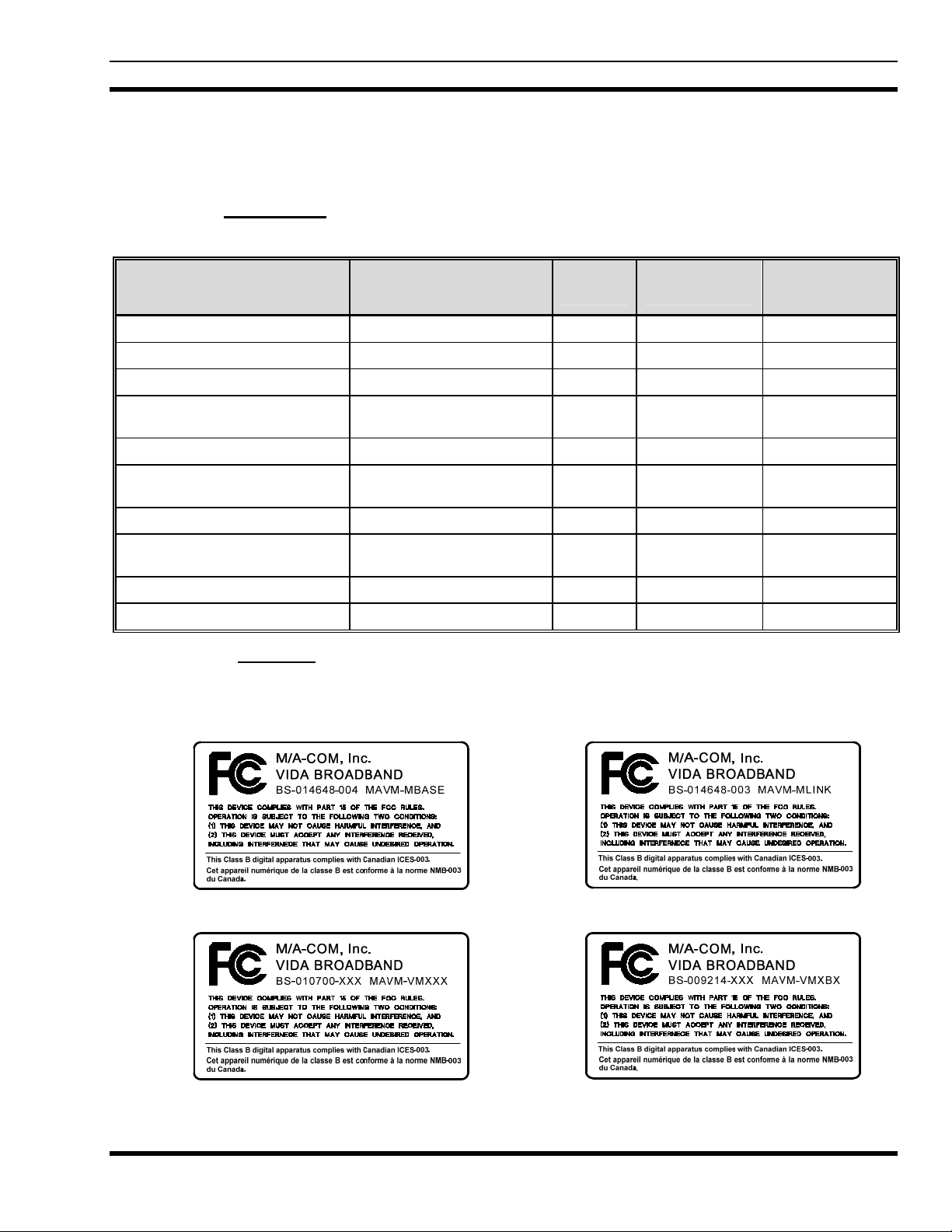
1.1.2 Receiver
This receiver associated with this transmitting device has been tested and declared to meet the regulatory
requirements defined in the following sub-sections. Associated FCC labelling is shown below.
B510 Base Station
MultiLink Station
Subscriber Station (Client)
9
Base Station (5 MHz channel only)
Page 11
MM-014720-001, Rev. A
1.1.3 FCC Compliance
This device complies with Part 15 of the FCC Rules. Operation is subject to the condition that this device
does not cause harmful interference.
This equipment has been tested and found to comply with the limits for a Class B digital device, pursuant
to Part 15 of the FCC Rules. These limits are designed to provide reasonable protection against harmful
interference in a residential installation. This equipment generates, uses, and can radiate radio frequency
energy and, if not installed and used in accordance with the instructions, may cause harmful interference
to radio communications. However, there is no guarantee that interference will not occur in a particular
installation. If this equipment does cause harmful interference to radio or television reception, which can
be determined by turning the equipment off and on, the user is encouraged to try to correct the
interference by one or more of the following measures:
• Reorient or relocate the receiving antenna.
• Increase the separation between the equipment and receiver.
• Connect the equipment into an outlet on a circuit different from that to which the receiver is
connected.
• Consult the dealer or an experienced radio/TV technician for help.
1.1.4 Industry Canada
This Class B digital apparatus complies with Canadian ICES-003.
Cet appareil numérique de la classe B est conforme à la norme NMB-003 du Canada.
The installer of this radio equipment must ensure that the antenna is located or
pointed such that it does not emit RF field in excess of Health Canada limits for the
general population; consult Safety Code 6, obtainable from Heath Canada’s website
www.hc-sc.gc.ca/rpb.
1.2 RF ENERGY EXPOSURE INFORMATION FOR FIXED OPERATION
1.2.1 Maximum Permissible Exposure Limits
DO NOT TRANSMIT with a station and antenna when persons are within the MAXIMUM
PERMISSIBLE EXPOSURE (MPE) Radius of the antenna. The MPE Radius is the minimum distance
from the antenna axis that ALL persons should maintain in order to avoid RF exposure higher than the
allowable MPE level set by the FCC.
FAILURE TO OBSERVE THESE LIMITS MAY ALLOW ALL PERSONS
WITHIN THE MPE RADIUS TO EXPERIENCE RF RADIATION
ABSORPTION, WHICH EXCEEDS THE FCC MAXIMUM PERMISSIBLE
EXPOSURE (MPE) LIMIT. IT IS THE RESPONSIBILITY OF THE STATION
LICENSEE TO ENSURE THAT THE MAXIMUM PERMISSIBLE EXPOSURE
LIMITS ARE OBSERVED AT ALL TIMES DURING STATION
TRANSMISSION. THE STATION LICENSEE IS TO ENSURE THAT NO
BYSTANDERS ARE WITHIN THE RADIUS LIMITS.
10
Page 12

MM-014720-001, Rev. A
1.2.2 Determining MPE Radius
THE MAXIMUM PERMISSIBLE EXPOSURE RADIUS is unique for each site and is determined
based on the complete installation environment (i.e. co-location, antenna type, transmit power level, etc.).
Determination of the MPE distance is the responsibility of the VIDA Broadband user. Calculation of the
MPE radius is required as part of the installation. The Limit for Uncontrolled Exposure Power Density
(P
) is 10 W/m2 for fixed mounted device.
d
The Tyco Electronics 4.9 GHz VIDA Broadband stations may be installed as a fixed mounted radio.
After installation and commissioning, the safe distance from the 9 dBi omnidirectional antenna is greater
than 20 cm (8-inches).
Table 1-1: MPE Minimum Distance Calculation for Fixed Installations Using High Gain Antennas
Effective
Antenna Gain
(dBi)
<10 0.20 0.65 0.20 0.65
11 0.20 0.65 0.22 0.73
12 0.20 0.65 0.25 0.82
13 0.20 0.65 0.28 0.92
14 0.20 0.65 0.32 1.04
15 0.20 0.65 0.35 1.16
16 0.20 0.65 0.40 1.31
17 0.20 0.65 0.45 1.47
18 0.22 0.73 0.50 1.64
19 0.25 0.82 0.56 1.84
20 0.28 0.92 0.63 2.07
21 0.32 1.04 0.71 2.32
22 0.35 1.16 0.79 2.61
23 0.40 1.31 0.89 2.92
24 0.45 1.47 1.00 3.28
25 0.50 1.64 1.12 3.68
26 0.56 1.84 1.26 4.13
>26
Low Power Fixed Clients (0.1 Watts) High Power Fixed Stations (0.5 Watts)
Minimum Safe
Distance (Meters)
Minimum Safe
Distance (Feet)
Reduce Transmitter Power as required by FCC
Minimum Safe
Distance (Meters)
Minimum Safe
Distance (Feet)
1.2.2.1 MPE Calculation for omnidirectional Antenna
This MPE Minimum Distance Calculation is based on using a 9 dBi gain omnidirectional antenna
mounted directly to the station RF port.
Basic Tyco Electronics 4.9 GHz VIDA Broadband station specifications:
P: Maximum Peak Conducted Power = 27 dBm
G: Maximum Omni Antenna Gain = 9 dBi
Frequency Range = 4.90 to 4.99 GHz
R: Minimum Distance between User and Antenna = 0.2 m
11
Page 13
MM-014720-001, Rev. A
Equation from FCC:
Pd = P * GN / ( 4 * π * Rmin 2 )
Pd = 0.5 W * 7.94 / (4 * 3.1415926 * 0.2 2) = 7.9 W / m2 < 10 W / m
The calculation indicates that the minimum 0.2 meter distance between user and the omnidirectional
antenna (directly mounted to the station RF port) is required when operating the Tyco Electronics 4.9
GHz VIDA Broadband Client.
1.2.2.2 MPE Calculation for Directional Antenna
This MPE Minimum Distance Calculation is based on using a directional antenna with more than 9 dBi
antenna gain.
Basic Tyco Electronics 4.9 GHz VIDA Broadband station specifications:
P: Maximum Peak Conducted Power = 27 dBm;
2
G: Maximum Omni Antenna Gain – Cable Loss = 27 dBi – 1 dB = 26 dBi; (Use numerical G
for the calculation ): G
= 10 ^ (G /10)); For G = 26 dBi, GN = 10 ^ (26 /10) = 398
N
value
N
Frequency Range = 4.90 to 4.99 GHz;
: Minimum Distance between user and antenna to comply with FCC MPE Level (10 W / m2 );
R
min
Equation from FCC:
Pd = P * GN / ( 4 * π * R
= SQRT( 0.5 W * GN / (4 * 3.1415926 * 10 ) )
R
min
= 1.26 m, for G =26 (i.e., GN = 398 )
R
min
The calculation provides guidelines for users to estimate the minimum safe distance when a high gain
antenna is connected to the Tyco Electronics 4.9 GHz VIDA Broadband station. The user should always
keep a safe distance from antenna greater than 20 cm or SQRT (3.9789E-3 * G
The following table lists fixed installation’s minimum distance for different Effective Antenna System
Gain Levels (Antenna Gain – Feeder Cable Loss). In all cases, the minimum safe distance defined in
Table 1-1 or 0.2 meters (8 inches), whichever is greater, is the recommended minimum safe distance for
fixed installations.
min
2
)
).
N
1.2.3 Safety Training Information
YOUR TYCO ELECTRONICS VIDA BROADBAND CLIE NT GENERATES RF
ELECTRO-MAGNETIC ENERGY DURING TRANSMIT MODE. THIS
CLIENT IS DESIGNED FOR AND CLASSIFIED AS “OCCUPATIONAL USE
ONLY” MEANING IT MUST BE USED ONLY IN THE COURSE OF
EMPLOYMENT BY INDIVIDUALS AWARE OF THE HAZARDOUS RF
ENERGY AND THE WAYS TO MINIMIZE EXPOSURE. THIS STATION IS
NOT INTENDED FOR USE BY THE “GENERAL POPULATION” IN AN
UNCONTROLLED ENVIRONMENT. IT IS THE RESPONSIBILITY OF TH E
LICENSEE TO ENSURE THAT THE MAXIMUM PERMISSIBLE EXPOSURE
LIMITS ARE OBSERVED AT ALL TIMES DURING TRANSMISSION. THE
STATION LICENSEE IS TO ENSURE THAT NO BYSTANDERS COME
WITHIN THE RADIUS OF THE LIMITS
12
Page 14
MM-014720-001, Rev. A
When licensed by the FCC, this station complies with the FCC RF exposure limits when persons are
beyond the MPE radius of the antenna. In addition, your Tyco Electronics VIDA Broadband station
installation complies with the following Standards and Guidelines with regard to RF energy and
electromagnetic energy levels and evaluation of such levels for exposure to humans:
FCC OET Bulletin 65 Edition 97-01 Supplement C, Evaluating Compliance with FCC Guidelines
for Human Exposure to Radio Frequency Electromagnetic Fields.
American National Standards Institute (C95.1 – 1992), IEEE Standard for Safety Levels with
Respect to Human Exposure to Radio Frequency Electromagnetic Fields, 3 kHz to 300 GHz.
American National Standards Institute (C95.3 – 1992), IEEE Recommended Practice for the
Measurement of Potentially Hazardous Electromagnetic Fields – RF and Microwave.
To ensure that your exposure to RF electromagnetic energy is within the FCC
allowable limits for occupational use, do not operate the station in a manner that
CAUTION
CAUTION
would create an MPE distance in excess of that allowable by the FCC.
Changes or modifications not expressly approved by Tyco Electronics Inc. could
void the user’s authority to operate the equipment.
1.2.4 Contact Information
For additional information on exposure requirements or other information, contact Tyco Electronics, Inc.
at 1-800-528-7711 or at
http://www.tewireless.com.
1.3 RF ENERGY EXPOSURE INFORMATION FOR MOBILE OPERATION
The FCC requires licensees and manufacturers to meet radio frequency radiation exposure compliance as
defined by FCC rule 47 CFR §2.1091 and as discussed in FCC document OET Bulletin 65: Evaluating
Compliance with FCC Guidelines for Human Exposure to Radiofrequency Electromagnetic Fields.
Page 5 of OET Bulletin 65, Supplement C, subtitled: Mobile Devices states the following:
“The FCC rules for evaluating mobile devices for RF compliance are found in 47 CFR §2.1091.
For purposes of RF exposure evaluation, a mobile device is defined as a transmitting device
designed to be used in other than fixed locations and to be generally used in such a way that a
separation distance of at least 20 centimeters is normally maintained between the transmitter's
radiating structures and the body of the user or nearby persons.”
Page 7 of OET Bulletin 65, Section 2, subtitled: Guidelines for evaluating Mobile and Portable Devices
states the following:
“Mobile devices identified in 47 CFR §2.1091 that operate at 1.5 GHz or below with an effective
radiated power (ERP) of 1.5 watts or more, or those that operate at frequencies above 1.5 GHz
with an ERP of 3.0 watts or more are required to perform routine environmental evaluation for RF
exposure prior to equipment authorization or use; otherwise, they are categorically excluded.”
The Tyco Electronics 4.9 GHz Broadband Client radio with 0.5 Watt RF output, installed as a mobile
device using the 5.5 dBi mobile antenna and cable mounts referenced in Table 1-2 has a calculated worst
case ERP of 1.78 Watts relative to an
isotropic radiator (EIRP). Therefore, it can be concluded that a
Tyco Electronics 4.9 GHz Client radio installed as a mobile device using the Tyco Electronics
13
Page 15
MM-014720-001, Rev. A
recommended mobile antenna system is categorically excluded from any requirement to perform routine
environmental evaluation for RF exposure. This is true with other mobile antenna systems having gains
up to 7.7 dBi.
CAUTION
This two-way radio uses electromagnetic energy in the radio frequency (RF) spectrum to provide
communications between two or more users over a distance. It uses RF energy or radio waves to send
and receive calls. RF energy is one form of electromagnetic energy. Other forms include, but are not
limited to, electric power, sunlight, and x-rays. RF energy, however, should not be confused with these
other forms of electromagnetic energy, which, when used improperly, can cause biological damage. Very
high levels of x-rays, for example, can damage tissues and genetic material.
Experts in science, engineering, medicine, health, and industry work with organizations to develop
standards for exposure to RF energy. These standards provide recommended levels of RF exposure for
both workers and the general public. These recommended RF exposure levels include substantial margins
of protection. All two-way radios marketed in North America are designed, manufactured, and tested to
ensure they meet government established RF exposure levels. In addition, manufacturers also
recommend specific operating instructions to users of two-way radios. These instructions are important
because they inform users about RF energy exposure and provide simple procedures on how to control it.
Please refer to the following websites for more information on what RF energy exposure is and how to
control your exposure to assure compliance with established RF exposure limits.
Changes or modifications not expressly approved by Tyco Electronics could void the
user's authority to operate the equipment and may require the user to perform routine
environmental evaluation of the mobile installation.
http://www.fcc.gov/oet/rfsafety/rf-faqs.html
http://www.osha.gov./SLTC/radiofrequencyradiation/index.html
Table 1-2 lists the recommended minimum lateral distance for a controlled
environment and for unaware bystanders in an uncontrolled environment, from
transmitting types of antennas the at rated radio power for nomadic Client
radios installed in a vehicle. Transmit only when unaware bystanders are at
CAUTION
least the uncontrolled recommended minimum lateral distance away from the
transmitting antenna.
Table 1-2: MPE Minimum Distance Calculation for Nomadic Client Installations
4.9 GHz CLIENT WITH 0.5 WATT OUTPUT IN NOMADIC OPERATION
(MOUNTED IN A VEHICLE) USING THE SPECIFIED ANTENNA AND
MOUNTS
ANTENNA & MOUNT
Antenna: MAXRAD (B)MEFC49005HF (5.5 dBi gain)
Mount: MAXRAD MHFML195C (Permanent)
Antenna: MAXRAD (B)MEFC49005HF (5.5 dBi gain)
Mount: MAXRAD GMHFML195C (Magnetic)
(Watts)
< 3.0 20 cm 20 cm
< 3.0 20 cm 20 cm
ERP
RECOMMENDED MINIMUM LATERAL
DISTANCE FROM TRANSMITTING ANTENNA
CONTROLLED UNCONTROLLED
14
Page 16

MM-014720-001, Rev. A
1.3.1 Nomadic Antennas
This device must not be co-located or operated in conjunction with any other antenna or
transmitter.
Install the radio’s antenna (refer to Table 1-2 for applicable antenna part numbers) in the center of the
vehicle’s roof. These nomadic antenna installation guidelines are limited to metal body motor vehicles or
vehicles with appropriate ground planes. The antenna installation should additionally be in accordance
with the following:
• The requirements of the antenna manufacturer/supplier included with the antenna.
• Installation instructions in this manual, including any minimum antenna cable lengths.
• The installation manual providing specific information of how to install the antennas to facilitate
recommended operating distances to all potentially exposed persons.
• Use only the Tyco Electronics approved/supplied antenna(s) or approved replacement antenna.
Unauthorized antennas, modifications, or attachments could damage the radio and may violate FCC
regulations.
1.3.2 Approved Accessories
This radio has been tested and meets the FCC RF guidelines when used with the Tyco Electronics
accessories supplied or designated for use with this product. Use of other accessories may not ensure
compliance with the FCC’s RF exposure guidelines, and may violate FCC regulations.
For a list of Tyco Electronics approved accessories refer to the product manuals, Tyco Electronics’
Products and Services Catalog, or contact Tyco Electronics at 1-800-528-7711.
1.3.3 Occupational Safety Guidelines and Safety Training Information
To ensure bodily exposure to RF electromagnetic energy is within the FCC allowable limits for
occupational use. Always adhere to the following basic guidelines:
1. The push-to-talk button should only be depressed when intending to send a voice message.
2. The radio should only be used for necessary work-related communications.
3. The radio should only be used by authorized and trained personnel. It should never be operated by
children.
4. Do not attempt any unauthorized modification to the radio. Changes or modifications to the radio
may cause harmful interference and/or cause it to exceed FCC RF exposure limits. Only qualified
personnel should service the radio.
5. Always use Tyco Electronics authorized accessories (antennas, control heads, speakers/mics, etc.).
Use of unauthorized accessories can cause the FCC RF exposure compliance requirements to be
exceeded.
The information listed above provides the user with information needed to make him or her aware of a RF
exposure, and what to do to assure that this radio operates within the FCC exposure limits of this radio.
15
Page 17

MM-014720-001, Rev. A
1.3.4 Common Hazards
The operator of any mobile radio should be aware of certain hazards common to
the operation of vehicular radio transmissions. Possible hazards include but are
not limited to:
• Explosive Atmospheres — Just as it is dangerous to fuel a vehicle while its motor running, be sure
to turn the radio OFF while fueling the vehicle. If the radio is mounted in the trunk of the vehicle,
DO NOT transport containers of fuel in the trunk.
Areas with potentially explosive atmosphere are often, but not always, clearly marked. Turn the radio
OFF when in any area with a potentially explosive atmosphere. It is rare, but not impossible that the
radio or its accessories could generate sparks.
• Interference To Vehicular Electronic Systems — Electronic fuel injection systems, electronic anti-
skid braking systems, electronic cruise control systems, etc., are typical of the types of electronic
devices that can malfunction due to the lack of protection from radio frequency (RF) energy present
when transmitting. If the vehicle contains such equipment, consult the dealer for the make of vehicle
and enlist his aid in determining if such electronic circuits perform normally when the radio is
transmitting.
• Electric Blasting Caps — To prevent accidental detonation of electric blasting caps, DO NOT use
two-way radios within 1000 feet (305 meters) of blasting operations. Always obey the “Turn Off
Two-Way Radios” (or equivalent) signs posted where electric blasting caps are being used. (OSHA
Standard: 1926.900).
• Radio Frequency Energy — To prevent burns or related physical injury from radio frequency
energy, do not operate the transmitter when anyone outside of the vehicle is within the minimum safe
distance from the antenna as specified in Table 1-1. Refer to Section 1.2 for additional information.
• Vehicles Powered By Liquefied Petroleum (LP) Gas — Radio installation in vehicles powered by
liquefied petroleum gas, where the LP gas container is located in the trunk or other sealed-off space
within the interior of the vehicle, must conform to the National Fire Protection Association standard
NFPA 58. This requires:
o The space containing the radio equipment must be isolated by a seal from the space containing
the LP gas container and its fittings.
o Outside filling connections must be used for the LP gas container.
o The LP gas container space shall be vented to the outside of the vehicle.
• Vehicles Equipped with Airbags — For driver and passenger safety, avoid mounting the radio or
any other component above or near airbag deployment areas. In addition to driver-side and
passenger-side front-impact airbags, some vehicles may also be equipped with side-impact airbags.
For occupant safety, verify the location of all airbags within the vehicle before installing the radio
equipment.
16
Page 18
MM-014720-001, Rev. A
1.3.5 Operating Rules and Regulations
Two-way FM radio systems must be operated in accordance with the rules and regulations of the local,
regional, or national government.
In the United States, the mobile radio must be operated in accordance with the rules and regulations of the
Federal Communications Commission (FCC). Operators of two-way radio equipment must be thoroughly
familiar with the rules that apply to the particular type of radio operation. Following these rules helps
eliminate confusion, assures the most efficient use of the existing radio channels, and results in a
smoothly functioning radio network.
Under U.S. law, operation of an unlicensed radio transmitter within the jurisdiction of
the United States may be punishable by a fine of up to $10,000, imprisonment for up to
CAUTION
When using a two-way radio, remember these rules:
• It is a violation of FCC rules to interrupt any distress or emergency message. The radio operates in
much the same way as a telephone “party line.” Therefore, always listen to make sure the channel is
clear before transmitting. Emergency calls have priority over all other messages. If someone is
sending an emergency message – such as reporting a fire or asking for help in an accident, do not
transmit unless assistance can be offered.
two (2) years, or both.
• The use of profane or obscene language is prohibited by Federal law.
• It is against the law to send false call letters or false distress or emergency messages. The FCC
requires keeping conversations brief and confines them to business. To save time, use coded
messages whenever possible.
• Using the radio to send personal messages (except in an emergency) is a violation of FCC rules. Send
only essential messages.
• It is against Federal law to repeat or otherwise make known anything overheard on the radio.
Conversations between others sharing the channel must be regarded as confidential.
• The FCC requires self-identification at certain specific times by means of call letters. Refer to the
rules that apply to the particular type of operation for the proper procedure.
• No changes or adjustments shall be made to the equipment except by an authorized or certified
electronics technician.
1.3.6 Mobile Operating Tips
The following conditions tend to reduce the effective range of two-way radios and should be avoided
whenever possible:
• Operating the radio in areas of low terrain, or while under power lines or bridges.
• Obstructions such as mountains and buildings.
In areas where transmission or reception is poor, communication improvement may
sometimes be obtained by moving a few yards in another direction, or moving to a higher
elevation.
17
Page 19
MM-014720-001, Rev. A
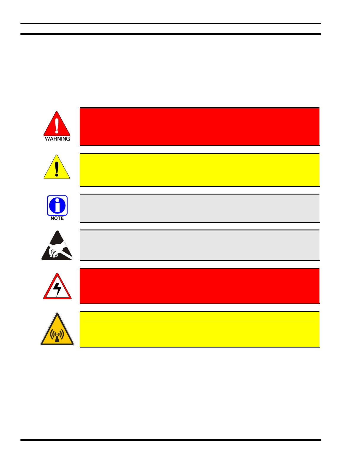
1.4 SAFETY SYMBOL CONVENTIONS
The following conventions may be used in this manual to alert the user to general safety precautions that
must be observed during all phases of operation, service, and repair of this product. Failure to comply
with these precautions or with specific warnings elsewhere in this manual violates safety standards of
design, manufacture, and intended use of the product. Tyco Electronics assumes no liability for the
customer's failure to comply with these standards.
The WARNING symbol calls attention to a procedure, practice, or the like, which,
if not correctly performed or adhered to, could result in personal injury. Do not
proceed beyond a WARNING symbol until the conditions identified are fully
understood or met.
The CAUTION symbol calls attention to an operating procedure, practice, or the like,
which, if not performed correctly or adhered to, could result in a risk of danger, damage
CAUTION
to the equipment, or severely degrade the equipment performance.
The NOTE symbol calls attention to supplemental information, which may improve
system performance or clarify a process or procedure.
The ESD symbol calls attention to procedures, practices, or the like, which could expose
equipment to the effects of Electro-Static Discharge. Proper precautions must be taken
to prevent ESD when handling circuit modules.
The electrical hazard symbol is a WARNING indicating there may be an electrical
shock hazard present.
This symbol indicates the presence of a potential RF hazard.
18
Page 20

2. INTRODUCTION
2.1 ABOUT THIS MANUAL
The manual provides information for installing and configuring VIDA Broadband equipment as a system.
This manual is written for the communications professional responsible for planning, installing, and
implementing the VIDA Broadband Network.
2.2 REFERENCE MANUALS
It may be necessary to consult one or more of the following manuals when installing, operating, or
maintaining a VIDA Broadband Network.
Table 2-1: Related Documentation
Documentation Manual Number
VIDA Broadband BAS/UAS User’s Manual MM-011540-001
RNM/CNM User’s Manual MM1000018633
MM-014720-001, Rev. A
VIDA Broadband System Manual MM-011541-001
VIDA Broadband Base Station Product Manual MM-009804 -001
VIDA Broadband Client Product Manual MM-010539-001
VIDA Broadband B510 Base Station Product Manual MM-016895 -001
VIDA Broadband MultiLink Station Product Manual MM-013752-001
VIDA Broadband Network Services Installation and Configuration Manual MM-014640-001
VIDA Broadband Basic Network Applications Programming Guide MM-014641-001
VIDA Broadband Systems Troubleshooting Guide MM-014642-001
VIDA Broadband Systems RF Planning Guide MM-015601-001
19
Page 21

MM-014720-001, Rev. A
2.3 CUSTOMER SERVICE
2.3.1 Technical Assistance
The Technical Assistance Center's (TAC) resources are available to help with overall system operation,
maintenance, upgrades, and product support. TAC is the point of contact when answers are needed to
technical questions.
Product specialists, with detailed knowledge of product operation, maintenance, and repair provide
technical support via a toll-free (in North America) telephone number. Support is also available through
mail, fax, and e-mail.
For more information about technical assistance services, contact your sales representative, or contact the
Technical Assistance Center directly at:
North America: 1-800-528-7711
International: 1-434-385-2400
Fax Number: 1-434-455-6712
E-mail: tac@tycoelectronics.com
2.3.2 Customer Resource Center
If any part of the system equipment is damaged on arrival, contact the shipper to conduct an inspection
and prepare a damage report. Save the shipping container and all packing materials until the inspection
and the damage report are completed. In addition, contact the Customer Resource Center to make
arrangements for replacement equipment. Do not return any part of the shipment until you receive
detailed instructions from a Tyco Electronics representative.
Contact the Customer Resource Center at:
North America:
Phone Number: 1-800-368-3277 (toll free)
Fax Number: 1-800-833-7592 (toll free)
E-mail: CustomerFocus@tycoelectronics.com
International:
Phone Number: 1-434-455-6403
Fax Number: 1-434-455-6676
E-mail: InternationalCustomerFocus@tycoelectronics.com
20
Page 22
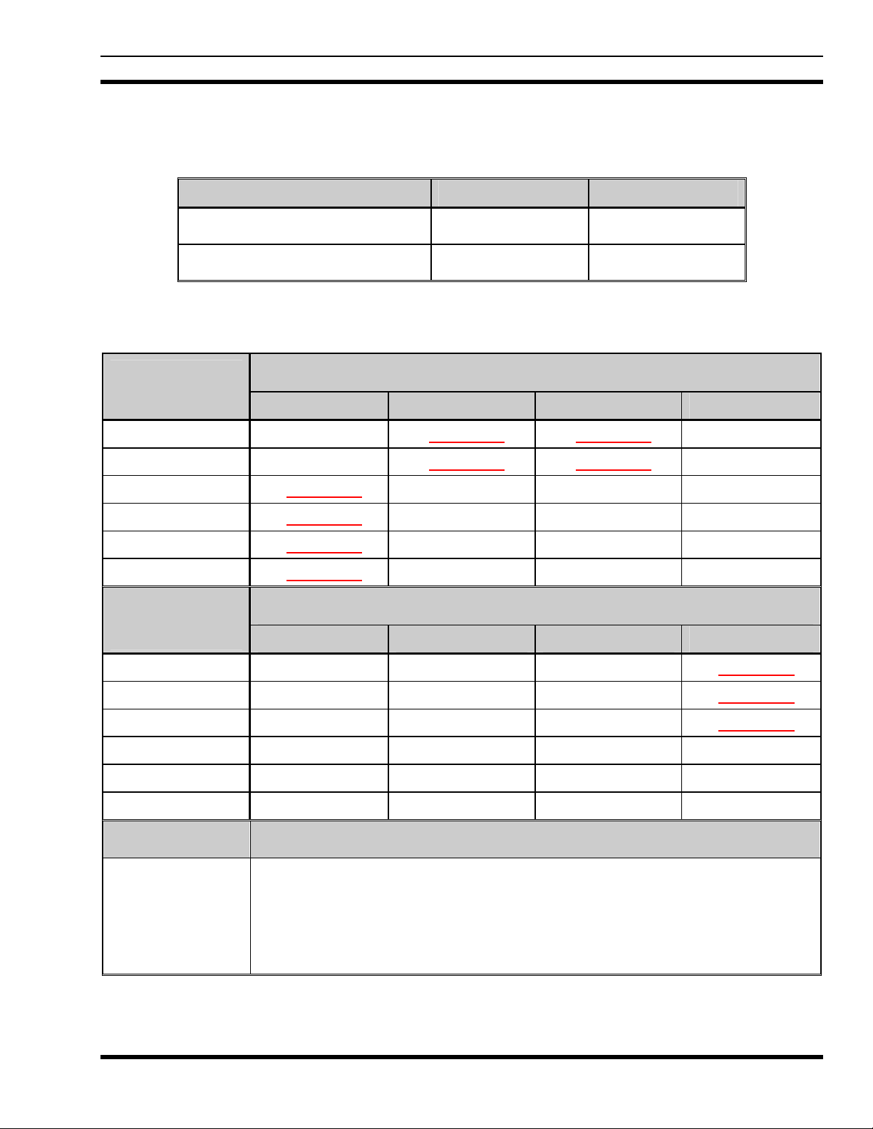
2.4 SOFTWARE COMPATIBILITY
Table 2-2: Current Software Releases
Media Part Number Version
Base Station Media Kit SK-014991-001 Version R3B
Subscriber Station Media Kit SK-016517-001 Version R7F
Table 2-3: VIDA Broadband Software Compatibility Chart
MM-014720-001, Rev. A
Base Station
(BS)
BS ver. 1.1.0 Compatible
BS ver. 1.1.2 Compatible
BS ver. R2A
BS ver. R2B
BS ver. R3A
BS ver. R3B
Ver. 3.0.9 Ver. 4.3.1 Ver. 4.3.2
Do Not Use
Do Not Use
Do Not Use
Do Not Use
Base Station
(BS)
BS ver. 1.1.0 Compatible Compatible Compatible
BS ver. 1.1.2 Compatible Compatible Compatible
BS ver. R2A Compatible Compatible Compatible
BS ver. R2B Compatible Compatible Compatible Compatible
BS ver. R3A Compatible Compatible Compatible Compatible
Ver. 0.194.0.0 Ver. 5.0.23 Ver. 6.6.1.0 Ver. 7.5.7.0
Unified Administrator System (UAS)
Do Not Use
Do Not Use
Compatible Compatible
Compatible Compatible
Compatible Compatible
Compatible Compatible
Do Not Use
Do Not Use
Subscriber Station (SS)
Do Not Use
Do Not Use
Do Not Use
BS ver. R3B Compatible Compatible Compatible Compatible
Notes:
1. Only the versions listed have been authorized for use in the field.
2. All UAS versions are compatible with all SS versions.
3. SS ver. 7.5.7.0 is incompatible with all BS versions prior to R2B.
4. All BS versions starting with R2A and later require UAS version R4x or later.
21
Page 23

MM-014720-001, Rev. A
2.5 TERMS AND ABBREVIATIONS
Table 2-4: Abbreviations
Term Definition
AES Advanced Encryption Standard
BAS Broadband Administration Server
BE Best Efforts
BS Base Station
CID Connection Identifier
CR Classifier Rule
DES Data Encryption Standard
DHCP Dynamic Host Configuration Protocol
EDACS Enhanced Digital Access Communications System
GPS Global Positioning System
IEEE Institute of Electrical & Electronics Engineers
JDBC Java Database Connectivity
JSP Java Server Page
LMR Land Mobile Radio
MAC Media Access Control
MIB Management Information Base
OFDM Orthogonal Frequency Division Multiplexing
QoS Quality of Service
RSS Received Signal Strength
SF Service Flow
SNMP Simple Network Management Protocol
SS Subscriber Station (Client)
TAC Technical Assistance Center
TFTP Trivial File Transfer Protocol
UAS Unified Administration System
22
UGS Unsolicited Grant Services
VIDA Voice, Interoperability, Data, and Access
WAN Wide Area Network
Page 24
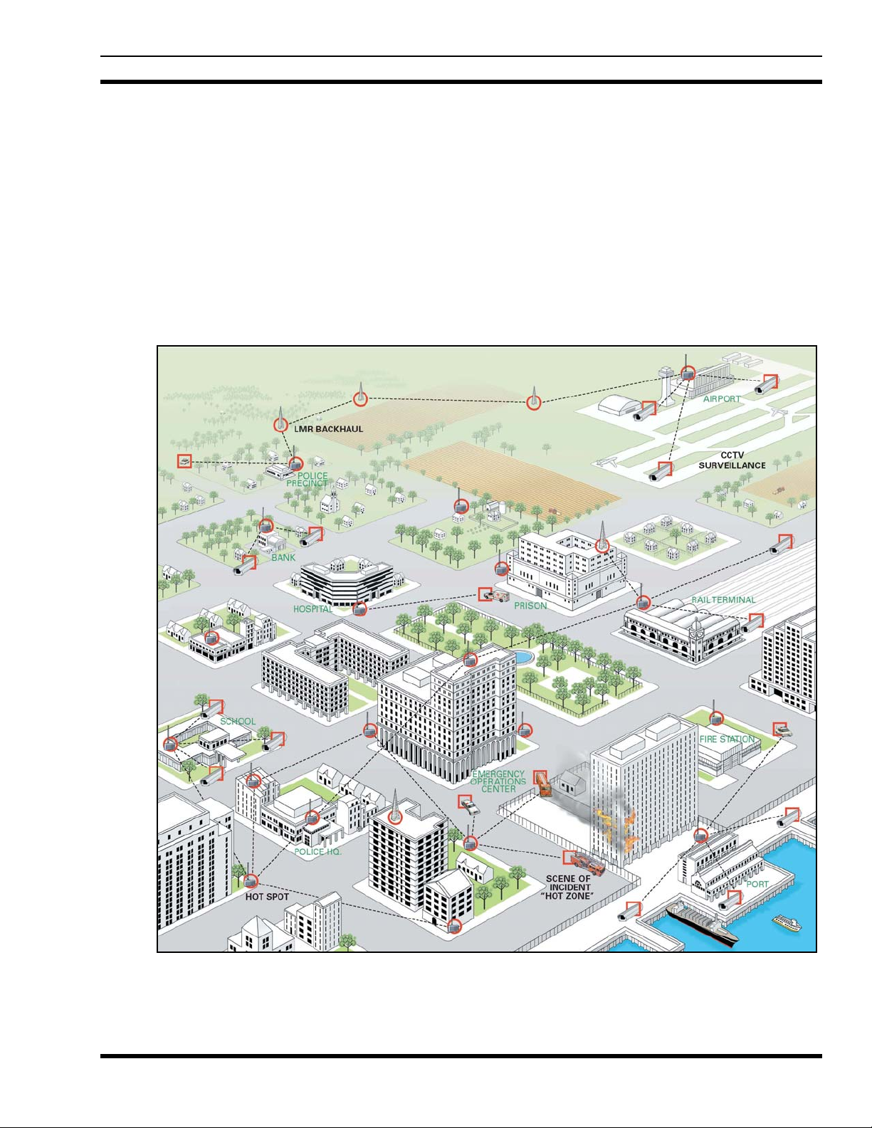
3. SYSTEM DESCRIPTION
VIDA Broadband provides integrated public safety grade wireless broadband video and data services for
mission-critical applications. VIDA Broadband combines the security of the licensed 4.9 GHz public
safety frequency band with the robust 802.16 communications industry standard to create a true public
safety broadband network. With this state-of-the-art network, public safety customers can implement
applications such as streaming video, web applications, economical licensed LMR backhaul, and other
bandwidth intensive applications. Since the network provides guaranteed Quality of Service (QoS), it is
especially suited for applications such as video surveillance, perimeter control, and mobile command.
VIDA Broadband is integrated with the VIDA network allowing seamless sharing of network resources,
including hardware network management and administration.
MM-014720-001, Rev. A
Figure 3-1: VIDA Broadband Network
23
Page 25

MM-014720-001, Rev. A
The basic architecture of the 4.9 GHz VIDA Broadband network is a point-to-multipoint network. A
system consists of one or more base station(s) and at least one or more clients per base station as shown in
Figure 3-1. There are two configurations of client
usually mounted outdoors with directional antennas and have a range of up to 10 miles. Nomadic clients
are vehicle mounted and use an omnidirectional antenna. The range of a nomadic client to base station is
typically a few hundred meters.
The VIDA Broadband Base Station implements the 802.16e-2005 OFDM protocol to deliver an over-theair throughput from 3 to 19 Mbps (for 5 MHz channel) and 3 to 38 Mbps (for 10 MHz channel). All
communication over the wireless channel is scheduled by the base station, with contention slots provided
for the VIDA Broadband Client to request bandwidth. This coordinated scheduling feature of the
protocol provides significant advantages such as:
• Minimizes contention between clients.
• Maximizes channel utilization.
• Maximizes ability to coordinate frequency usage among users.
• Enables guaranteed bandwidth services for critical applications.
3.1 SYSTEM COMPONENTS
devices; fixed and nomadic. Fixed client devices are
The VIDA Broadband Base and Subscriber Stations are designed for easy mounting on a variety of
outdoor structures including light poles and telephone poles. The base stations and clients in the VIDA
Broadband Network use IPC IP66-rated enclosures for operation in challenging environmental conditions,
and the UAS software is the same as that in use by numerous federal and public safety systems across
North America. The VIDA Broadband client can also be vehicle mounted for nomadic applications using
an optional vehicle mounting kit.
The VIDA Broadband system comprises the following:
• Base Station Equipment (BS): VIDA Broadband Base Stations provide the coordinating point
in a point-multipoint network, transferring data between an IP network and remote subscriber
stations as well as managing the subscriber stations on the network.
• Subscriber Station (SS): VIDA Broadband Client used to transfer data from a fixed or nomadic
location to the base station.
• MultiLink Station: VIDA Broadband MultiLink Stations provide full capacity network
extension, transferring data between an IP network and remote subscriber stations, with no loss of
capacity.
• Networking Equipment: Standard Switches and Routers supporting connections to the
backbone or Intranet.
• Management Systems: UAS Management, RNM system monitoring, and other Operation
Support Systems.
3.2 BASE STATION
The VIDA Broadband Base Stations provide the public safety grade infrastructure for the 4.9 GHz VIDA
Broadband network. The base stations are FCC-certified and implement a 5 or 10 MHz channel version of
the IEEE 802.16e-OFDM profile in the 4.90 to 4.99 GHz (4.94 to 4.99 GHz for BS-009214 base stations)
communications band. This implementation allows using up to ten 5 MHz channels with the BS-009214 base
24
Page 26
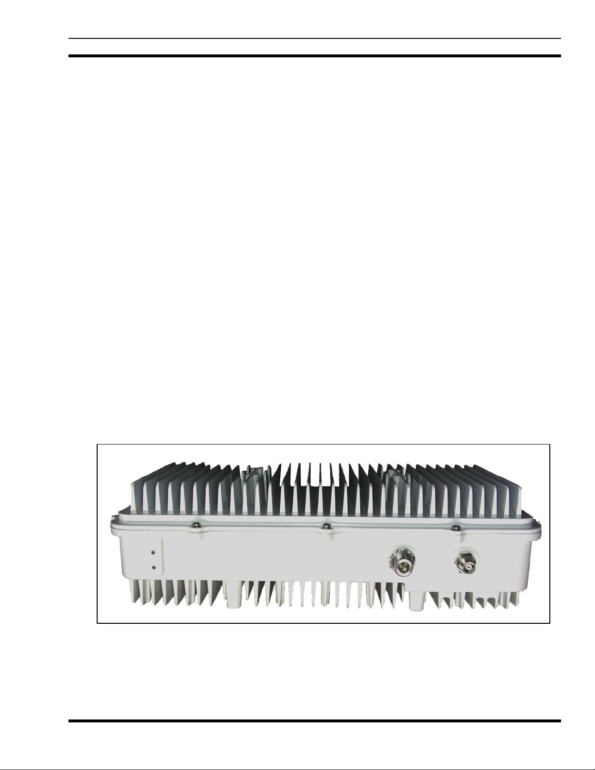
MM-014720-001, Rev. A
stations or up to eighteen possible 5 MHz channels (10 Public Safety and 8 Federal) or nine possible 10 MHz
channels (5 Public Safety and 4 Federal) with the BS-014648 base station. The base stations transmit up to 27
dBm power (0.5W) satisfying the high-power FCC mask and deliver from 1 to 19 Mbps (for a 5 MHz
channel) and 3 to 38 Mbps (for a 10 MHz channel) over-the-air throughput.
The base station schedules all communication over the wireless channel, with contention slots provided for
subscriber stations to request bandwidth. Based on traffic loading, multiple “connections” can be established
between the base station and each subscriber station in the network, with different QoS for each connection,
allowing for great flexibility when designing a network. Low priority processes (such as e-mail) can be
mapped to best effort services while high priority processes (such as streaming video or LMR backhaul) can
be mapped to unsolicited grant services (UGS) which offer guaranteed throughput. Network convergence is
provided in the form of 802.16 classifier rules that ensure network level QoS over the airlink.
Tyco Electronics offers four base station configurations:
• MAVM-VMXBA (BS-009214-001) - AC powered with copper Ethernet port (5 MHz channel)
• MAVM-VMXBC (BS-009214-003) - DC powered with copper Ethernet port (5 MHz channel)
• MAVM-VMXBD (BS-009214-002) - DC powered with Fiber Optic Ethernet port (5 MHz
channel)
• MAVM-MBASE (BS-014648-004) - DC powered with Copper Ethernet and Fiber Optic ports
(5 MHz or 10 MHz channel)
The AC model operates on 110 Vac and uses a 100Base-TX Ethernet based data port configuration. The DC
models require +24 Vdc, have built-in surge protection, and have either a 100Base-TX Ethernet based data
port or a 100Base-FX Fiber Optic data port. The BS-014648 DC powered base station has both 100Base-TX
and 100Base-FX ports.
The base station, shown in Figure 3-2, is housed in a steel NEMA 4 enclosure that satisfies IP66 requirements
for outd
oor deployments.
Figure 3-2: VIDA Broadband B510 (BS-014648-004) Base Station
25
Page 27
MM-014720-001, Rev. A
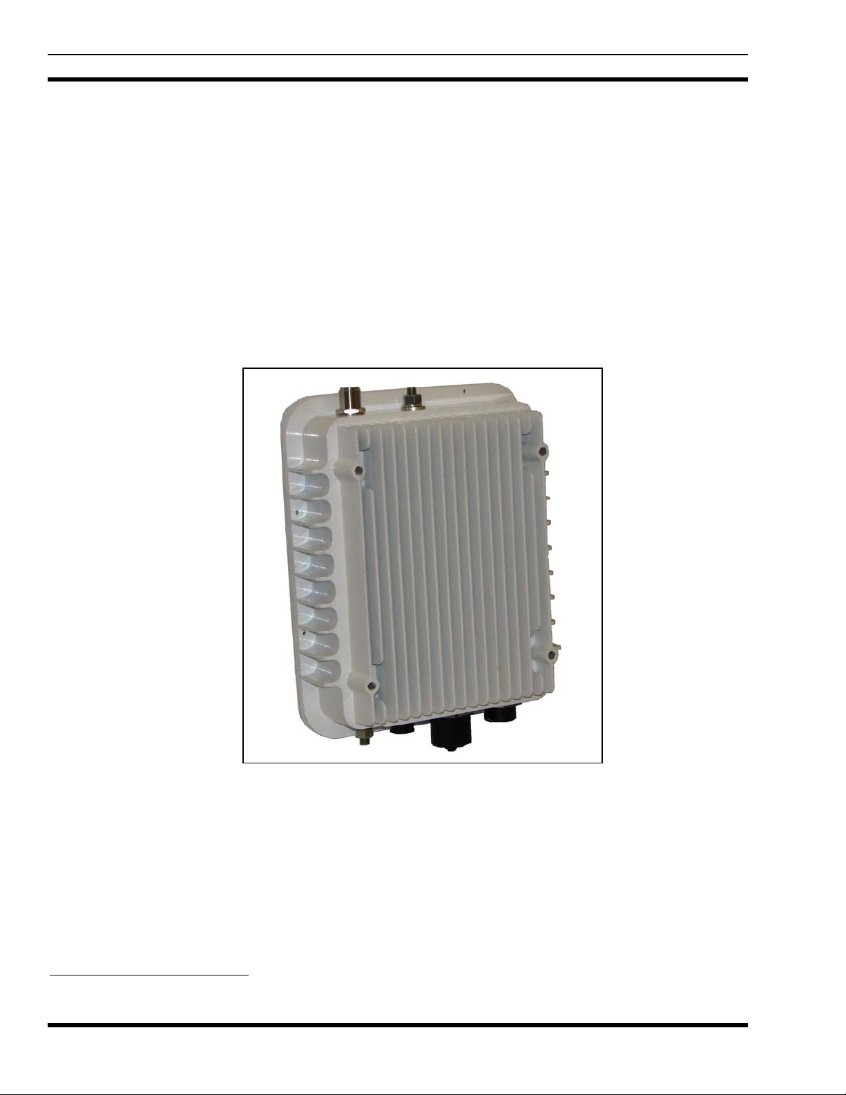
3.3 SUBSCRIBER STATION (CLIENT)
The 4.9 GHz VIDA Broadband Subscriber Station (SS), also referred to as a Client, is shown in Figure
3-3. The Client is housed in a ruggedized enclosure suitable for nomadic or outdoor installations. The
NEMA 4 housing satisfies IP66 requirements for outdoor deployments. The Client is designed for
multiple mounting configurations to allow nomadic or fixed structure mounting.
• MAVM-VMCLL (BS-010700-001) - 0.1W, Copper Ethernet (5 MHz channel)
• MAVM-VMXCH (BS-010700-002) - 0.5W, AC/DC, Copper Ethernet (5 or 10 MHz channel)
• MAVM-VMCHN (BS-010700-002)
• MAVM-VMCHH (BS-010700-003) - 0.5W, DC, Fiber (w/surge protection) (5 or 10 MHz channel)
• MAVM-VMCLH (BS-010700-004) - 0.1W, DC, Fiber (w/surge protection) (5 MHz channel)
1
- Nomadic, 0.5W, DC, Copper Ethernet (5 or 10 MHz channel)
Figure 3-3: VIDA Broadband Client
The high power (0.5 Watt) copper model is available for fixed or nomadic applications and is approved
for 5 or 10 MHz channel bandwidth. The low power (0.1 Watt) copper model is typically installed in
fixed locations only and is only approved for 5 MHz channel operation. Both the high and low power
copper models are designed to operate on 11 to 30 Vdc or 16 to 26 Vac and use a 100Base-TX Ethernet
data port configuration. However, a DC supply is recommended in all applications for cleaner and lowernoise power.
The fiber models have built-in lightning protection, are powered by DC voltage only, and use a 100BaseFX Fiber Optic data port configuration.
1
High Power Copper Client supplied with nomadic installation kit.
26
Page 28

3.4 MULTILINK STATION
The VIDA Broadband MultiLink Station’s base and subscriber functionality operate on separate single
channels selected from the eighteen possible 5 MHz channels (10 Public Safety and 8 Federal) or nine
possible 10 MHz channels (5 Public Safety and 4 Federal) of the IEEE 802.16e-OFDM profile in the 4.90
to 4.99 GHz communications band. The MultiLink Station transmits up to 27 dBm power out each
antenna port and both satisfy the high power FCC mask. The MultiLink Station is DC powered and has
the option of operating with either Copper Ethernet 100Base-TX and/or Fiber 100Base-FX. The
MultiLink Station merges the features of a base station with a fully functional subscriber with the same
outline and similar weight as a base station-only device. The base station and subscriber functions share
the 100- Base-TX Ethernet and 100-Base-FX fiber optic data ports through the internal Ethernet switch.
The MultiLink Station is ideal for full capacity network extension
The MultiLink Station, shown in Figure 3-4, is identified as follows:
MM-014720-001, Rev. A
• MAVM-MLINK (BS-014648-003) – M
Figure 3-4: VIDA Broadband MultiLink Station
ultiLink Station with Built-in Subscriber Station
The VIDA Broadband MultiLink Station is housed in a steel NEMA 4 enclosure that satisfies IP66
requirements for outdoor deployments. To provide for flexible RF deployment configurations, the base
station and built-in subscriber station can use a combination of antenna mounting options, including:
• Direct or remote mounting of an omnidirectional antenna on the base station or subscriber station
• Direct or remote mounting of a directional antenna on the front face of the MultiLink station for
either the base station or subscriber station, or
• Direct or remote mounting of an antenna through the connection of an RF cable to the base
station or subscriber station.
27
Page 29

MM-014720-001, Rev. A
3.5 NETWORKING EQUIPMENT
The base station equipment is connected to the IP backbone through standard data communication and
telecommunication equipment. The 100Base-TX or 100Base-FX Fiber ports of the base station can be
connected directly to a multi-port router or an Ethernet switch.
The point-to-point link from the base station to the backbone can be either wired or wireless. Data to the
Internet is routed to the backbone through standard routers.
The subscriber stations may also use their 100Base-TX or 100Base-FX Fiber ports to connect directly to a
multi-port router or an Ethernet switch. Use of routers and switches depends on the site configuration
(point-to-point, multi-hop, backhaul, etc.) and associated equipment (cameras, cell site, etc.).
3.6 MANAGEMENT EQUIPMENT
Provisioning of the VIDA Broadband system is accomplished using the Unified Administration System
(UAS) installed on the Broadband Administration Server (BAS) or as part of the Regional VIDA
Manager (RVM) installed on a Sun Server.
For provisioning of a VIDA Broadband standalone system, the BAS is available in one of three
configurations. The BAS Laptop Server (CM-014992-003) configuration is useful when initial system
configuration is all that is required. For installations that may require frequent system changes or
adjustments, it is recommended to use the BAS Rack-mount Server (CM-014992-001) or the BAS Tower
Server (CM-014992-002).
For VIDA Broadband systems which are integrated with a radio communication system (P25, OpenSky,
etc.), the RVM UAS is required to configure/manage the broadband equipment from a centralized server.
3.6.1 Unified Administration System
The Unified Administration System (UAS) is the centralized access point from which the VIDA
Broadband network is provisioned. The network administrator uses the UAS to configure and provision
base stations, clients, service flows, and classifier rules to enable enforced QoS across the network.
Because VIDA Broadband uses the WiMAX scheduled protocol, the base stations are able to enforce
these rules over all traffic to provide guaranteed QoS. In addition, the network administrator can set up
and change mission-critical parameters (priorities, etc.) in real time to maximize performance during
specific incidents.
28
Page 30

MM-014720-001, Rev. A
Figure 3-5: Example of UAS Subscriber Stations Screen
3.6.2 Regional Network Manager
The Regional Network Manager (RNM), part of the Regional VIDA Manager (RVM) on a Sun Unix
Server, provides system status, fault, and performance data. In addition, the RNM monitors system
activity in real time and logs all significant events.
The RNM is a collection of applications and administrative programs that permit the user to view and
monitor the VIDA Broadband network components from a centralized access point. The RNM uses a
graphically oriented interface that creates a visual representation of the network.
A major feature of the RNM is the graphical visualizations of the VIDA Broadband network. For
example, the Network Viewer and Object List applications offer different representations of the
managed objects within the network (such as base stations, clients, routers, etc.). The Network Viewer
illustrates the hierarchical relationships, while the Object List allows you to specify powerful filtering
clauses. In both applications, the current status of each object is conveyed using descriptive color-coding.
The RNM also displays fault and performance information, allowing you to locate trouble spots in the
system and fix them quickly. It can also be set up to emit an audible alert when problems occur, thus
making it possible to quickly and effectively recover from problem situations.
29
Page 31

MM-014720-001, Rev. A
4. PLANNING A FIXED STATION INSTALLATION
Careful planning and preparation of any installation will always benefit the end result. Follow these
simple recommendations when planning your installation:
1. Always read and follow all installation instructions, local and national building and electrical codes,
and general safety rules.
2. Before beginning the installation, collect information from the Site Deployment Order (SDO) specific
to the site access such as:
• Permission to access the site.
• Important contact names and telephone numbers.
• Location of and directions to the site.
• Keys and/or lock combinations to access the site and equipment shelter (if any), or points of
contact to obtain them.
• Site entry alarm system pass-codes and/or disable keys.
• Information about work practices needed to work safely at the site.
3. Other important information that may or may not be included on the SDO includes:
• Type of mounting—metal pole, wooden pole, tower base, exterior wall, etc.
• Drawing or description of each site showing how the equipment is to be installed.
• Applicable inspections completed (pole installation, electrical, local build code, etc.).
• Installer must be aware of other transmitters and receivers on site that could cause interference to,
or be interfered with by, the broadband equipment. Strong signals from, or to, co-located
equipment may inflict permanent damage to either device.
VIDA Broadband equipment has a maximum allowed input power of 0 dBm in the 4.9
to 4.99 GHz band. Although other frequencies may have a higher threshold, any
signal, at any frequency, above 0 dBm presented to the Broadband equipment should
be cleared by the factory prior to installation.
4. We recommend pre-staging the equipment to become familiar with the specific hardware and cabling,
tooling, and supplies that are needed to complete the installation.
4.1 SITE EVALUATION
Before installing the VIDA Broadband Client, the System Engineer and Installer should plan the site
installation. Since higher RF frequencies do not readily pass through trees or buildings, consideration
should be given to the following:
30
• Ensure there are no obstructions (such as buildings or trees) in the radio path between base station
and client units.
• Ensure that any future building construction or tree growth will not obstruct the radio path.
Page 32

• Ensure there is sufficient clearance around the Fresnel Zone so there is minimal interference from
obstacles along the radio propagation path.
• Ensure the installation adheres to any local and national building codes and permits.
• Ensure sufficient electrical power is available at the installation site.
• When using directional antennas, align the antenna to maximize the Received Signal Strength
Indication (RSSI) from the base station.
• Ensure the area around an omnidirectional antenna is clear (at least 30 inches) so as not to distort
the RF pattern.
• Locate the client away from any sources of interference that could degrade the performance of the
equipment. Consult the RF Planning Guide, MM-015601-001 for additional information.
• Ensure the base station and clients are within each other’s maximum RF coverage range.
• Ensure maximum standard CAT-5 cable length connecting the client to the Ethernet LAN is 100
meters (328 ft.) and maximum antenna cable length is five (5) feet.
4.2 ELECTRICAL POWER
The input voltage source required depends on the model being installed. For example, clients use either
11 to 30 Vdc or 16 to 26 Vac. An AC powered base station requires 120 Vac, 50-60 Hz, and DC powered
base stations and the MultiLink station require 21 to 27 Vdc.
MM-014720-001, Rev. A
Careful consideration should be given regarding the voltage drop across the selected power cabling to
maintain the input power requirements. If a backup power source is desired, it must be provided by an
external backup power source.
Stations using Fiber optic cables use a DC input power source only. DO NOT apply an
AC power source to these stations.
CAUTION
DC Power Source Options
We recommend using power supplies that are FCC Part 15 Class A or B compliant. Using power
supplies that are not compliant could be in violation of FCC Regulations. It is the installer’s
responsibility to ensure the installation meets FCC Regulations.
4.3 SITE GROUNDING
Installers should review the recommended grounding procedures in the Tyco Electronics Site Grounding
and Lightning Protection Guidelines Manual, AE/LZT 123 4618/1 and ensure a suitable ground is
installed between the station ground lug and earth ground. Grounding must also be in compliance with
any local and national electrical codes.
31
Page 33

MM-014720-001, Rev. A
4.4 SURGE PROTECTION
When installing a VIDA Broadband Base Station, MultiLink Station, or Subscriber Station you should
always install external surge protectors to protect the system components from lightning or transient
damage. Table 4-1 lists surge protectors that have been tested in VIDA Br
available from Tyco Electronics. Detailed specifications for these devices can be found in Appendix C.1.
Table 4-1: Surge Protection Options
Part Number Description
PT-016508-001 RF Port Surge Protector, Coax, Type N, 4.9 GHz.
PT-016508-002 GPS Port Surge Protector, Coax, TNC.
PT-016508-003 Cat5e, RJ-45, Data Port Surge Protector.
PT-016508-004 Surge Protector, DC, Wire, 27 Vdc
PT-016508-005 Surge Protector, DC, Wire, 54 Vdc
PT-016508-006 Surge Protector, AC/DC, Wire, 24 Vac/ 30 Vdc
PT-016508-007 Surge Protector, Coax, BNC, CCTV, and PTZ Data
oadband systems and are
PT-016508-008 Surge Protector, Coax, BNC, CCTV
PT-016508-009 Surge Protector, AC, wire, 120 Vac
4.5 ANTENNA SELECTION
The VIDA Broadband Base Station, MultiLink Stations, and Subscriber Stations allow users to choose
from variety of antenna types and installation configurations.
4.5.1 Antenna Requirements
There are several basic “types” of antennas. Each type has certain advantages and disadvantages for
particular applications in microwave and broadband wireless networks. Antennas and any associated
cabling which connects the antenna to the Broadband equipment comprise an “Antenna System.” In this
Antenna System all cable loss is subtracted from the antenna gain, the result being the Effective Antenna
System gain. Generally, the antenna system used with a VIDA Broadband device must meet the
following requirements:
Omnidirectional Antenna: Vertical or Horizontal Polarization
9 dBi Effective Maximum System Gain
Directional Antenna: Linear Vertical or Horizontal
26 dBi Effective Maximum System Gain
(Reduction of Transmitter Power is required if the Effective Maximum
Antenna System Gain is greater than 26 dBi for 5 MHz operation or 29 dBi
for 10 MHz operation)
32
System antenna gain is defined as the antenna gain minus any cable or other losses between the base
station antenna port and the antenna.
Page 34

MM-014720-001, Rev. A
VIDA Broadband equipment is designed to use directional antennas with an antenna
system gain up to 26 dBi in a point-to-point or point-to-multipoint configuration.
In 5 MHz applications, the Transmitter Output Power must be reduced if the Effective
Antenna System Gain is greater than 26 dBi. The power reduction needs to be at least
equal to or greater than the amount the antenna system gain exceeds 26 dBi.
In 10 MHz applications, customers may use an Effective Maximum Antenna System Gain
up to 29 dBi before a power reduction is required. This is because of the Broadband
equipment’s self imposed 27 dBm maximum power; verses a permitted power of 30 dBm.
4.5.2 Antenna Types
The following paragraphs describe the different types of antennas that can be used with VIDA Broadband
devices. Table 4-2 contains a list of approved antennas. More detailed descri
be found in Appendix C.2.
ptions of the antennas can
Omnidirectional Antennas
An omnidirectional antenna is a vertical antenna. A vertical antenna’s radiation pattern or signal radiates
in all directions, losing power as the distance increases. Their radiation patterns are weaker directly
above or below the vertical plane. An omnidirectional antenna also picks up signals from all directions.
Grid Parabolic Antennas
The Grid parabolic antenna is a directional antenna that greatly reduces wind loading on a tower or other
mounting structures. Grid antennas have a lower front-to-back ratio than solid parabolic antennas. They
are also limited to a single polarization. They are ideal in applications where the best performance is not
required and tower and wind loading are the main concern.
Standard Parabolic Antennas
Standard parabolic antennas consist of a parabolic shaped reflector spun from a sheet of aluminum. The
parabolic shape focuses energy at the feed point of the antenna. The parabolic antennas have a narrow
focused beam of energy and relatively high gain compared to many other types of antennas. These
antennas will have a mounting system to attach the antenna to a pipe or tower leg.
High Performance Antennas
High Performance antennas are formed of aluminum, which is spun to precise tolerances. Then a shroud
is also fabricated of aluminum and fitted with a planar radome to protect the feed and provide for a
significant reduction in side lobes. Often manufacturers will use absorber material to improve the pattern
performance of the side lobes and front-to-back ratio.
Sector Antennas
Sector antennas are designed to provide segmented RF coverage over a selected (sector) area; sector
antennas deliver a wider beamwidth than point-to-point parabolic antennas. Antenna configurations can
consist of flat panel micro strip and slot radiating designs, as well as traditional parabolic configurations.
Some common horizontal beamwidths used include 60, 90, 120, and 180 degrees.
33
Page 35

MM-014720-001, Rev. A
Flat Panel Antennas
Flat panel antennas are designed for point-to-point and point-to-multi point applications. Typically, flat
panel antennas are designed to be lightweight, easy to install, aligned and durable for years of reliable
service. These antennas are ideal for concealment in many architectural environments. In addition to
pole mounting, the approved panel antenna can be mounted directly to the VIDA Broadband base station,
MultiLink station, or client.
Table 4-2: Antenna Options
Part Number Description
AN-013386-001 Antenna, Dish, 2 ft, 26.6 dBi, Type N Connector
AN-013386-002 Antenna, 90 degree Sector Panel, 16 dBi, Vertical polarization, Type N Connector
AN-013386-003 Antenna, Sector, 90 degree, 16 dBi, Horizontal, Type N Connector
AN-013386-004 Antenna, 60 degree Sector Panel, 17 dBi, Vertical polarization, Type N Connector
AN-013386-005 Antenna, Sector, 60 degree, 17 dBi, Horizontal, Type N Connector
AN-013386-006 Antenna, Grid, 2 ft, 26.4 dBi, Type N Connector
AN-013386-007 Antenna, Dish, 1 ft, 21.2 dBi, Type N Connector
AN-013386-008 Antenna, 10.5 degree Sector Panel, 1 ft, 21 dBi, Type N Connector
AN-013386-009 Antenna, Omnidirectional, 8 dBi, 16 degree, Type N Connector
AN-013386-010 Antenna, Dish, 2 ft, 6 degree, 27.7 dBi, Type N Connector
AN-013386-011 Antenna, Omnidirectional, Vertical polarization, 18 degree, 5.5 dBi, Type N Connector
AN-013386-012 Antenna, Omnidirectional, 8 degree, 9 dBi, Type N Connector
AN-013386-013 Antenna, Panel, 9 degree, 15 x 13 in., 20 dBi, Type N Connector
AN-013386-014 Antenna, 4.9 -5.85 GHz, 12 dBi, 180 Degree Sector Panel with type N Connector.
AN-013386-015 Antenna, 4.94-4.99 GHz, 15 dBi, 120 Degree Sector Panel with type N Connector.
4.6 INSTALLATION EXAMPLES
The following sections contain examples of various installations. These include:
34
Page 36

4.6.1 Sample Base Station Installation
MM-014720-001, Rev. A
2 3
1
W2 W1 W0
ACT
ACT
100 Mbps
100 Mbps
LINK
FASTETHERNET 0/1 FASTETHERNET 0/0 CONSOLE
CF
LINK
Cisco 3725
AUX
Figure 4-1: Sample Fiber Base Station Installation
35
Page 37

MM-014720-001, Rev. A
4.6.2 Sample Subscriber Station Installation
2 3
1
W2 W1 W0
ACT
ACT
100 Mbps
100 Mbps
LINK
FASTETHERNET 0/1 FASTETHERNET 0/0 CONSOLE
CF
LINK
Cisco 3725
AUX
36
Figure 4-2: Sample Fiber Subscriber Station Installation
Page 38

5. PRE-STAGING EQUIPMENT
5.1 BASE STATION CONFIGURATION
The base station is designed to acquire an IP address in one of the following ways:
• Default
The base station has a default IP address of 10.0.49.1. This address can be used to access the base
station as long as it has not been assigned an IP address via DHCP.
Once the base station has been given an IP address via DHCP, the default address is no
longer valid.
• Static
The base station can be configured to use a static IP address. The base station has a default static IP
address of 192.168.11.3. When the base station is running in static IP mode, both the default IP
address of 10.0.49.1 and the user assigned static IP address can be used to access the base station.
MM-014720-001, Rev. A
• DHCP
If the base station is configured for DHCP, it will always request an IP address via DHCP on boot up.
If a DHCP server responds to the request, the base station will continue to use the assigned IP address
until it is rebooted. If the base station does not receive an IP address via DHCP, due to no DHCP
server or a connectivity problem, it will use its last known IP address until it is rebooted. This
address is stored on the base station and will not change unless the base station is assigned a new IP
address via DHCP on a subsequent boot up or the base station is configured to use a static address. If
DHCP fails, both the last know IP address and the default IP address, which may be different, can be
used to access the base station.
When setting up a new BS, and before deploying it into the field, we recommend pre-configuring the BS
with the IP address that it will use in the field.
• If the BS will be using a static IP address, manually assign the IP address before installing the BS
in the field.
• If the BS will be using DHCP in the field, connect the BS to a DHCP server that contains the
actual IP address information that the BS will use in the field.
When the BS boots up for the first time, it will be connected to the DHCP server directly and will have
the ability to acquire an IP address from the DHCP server. The BS will then store the address as the last
know IP address. This way, if no DHCP server exists in the field’s network, or if there is a connectivity
problem with the BS in the field before a DHCP server is found, access to the BS will still be possible
through the last know IP address given to the BS.
37
Page 39

MM-014720-001, Rev. A
5.1.1 BS Configuration
To configure the BS with transmission parameters such as RF Attenuation and RF Channel/Frequency, a
configuration script is used. This script is called bs_config and can be found in the /ixa/wimax directory
in the base station.
The script takes time between configuration steps. After typing Enter, wait for the prompt
to come back before typing Enter again. If you do not wait for the prompt to return you
may cause the script to fail.
Step 1. Telnet into the BS
telnet –l root <BS IP Address>
password: tyco
Step 2. Execute Script
The telnet session will start you in the /ixa/wimax/ directory. From this directory execute the script:
./bs_config
The following output will appear:
--- Base station file configuration program ---
Mounting flash file systems
Please be patient, this may take several minutes...
Options:
1 - Keep current configuration. Copy the old files
2 - Manually re-configure the base station.
3 - Manually re-configure the base station with advanced options.
Choose Option 3.
Each step in the script will first show the current value of the setting. The script will then wait for you to
either type in a new value followed by the Enter key, or just press the Enter key to accept the current
value.
Step 3. Assign a Channel/Frequency
When prompted, enter the RF frequency that will be used by the BS. Refer to Table 5-1 for
channel/frequency
options (5 MHz offset 2500 kHz, 10 MHz offset 5000 kHz):
Enter channel in kHz, (range 4900000 – 500000):
38
Page 40

Table 5-1: Available Frequencies
5 MHz Frequencies 10 MHz Frequencies
4902500 4905000
4907500
4912500 4915000
4917500
4922500 4925000
4927500
4932500 4935000
4937500
4942500 4945000
MM-014720-001, Rev. A
4947500
4952500 4955000
4957500
4962500 4965000
4967500
4972500 4975000
4977500
4982500 4985000
4987500
Frequencies highlighted in gray are only available on 10 MHz products.
39
Page 41

MM-014720-001, Rev. A
Step 4. Set the RF Attenuation
When prompted, enter the RF attenuation to be used by the BS.
For instance, a setting of RF_ATTENUATION = 5 will result in max power, or a BS TX power of 26
dBm. Increasing the RF_ ATTENUATION value will result in decreasing the actual BS TX output
power. Table 5-2 lists the approximate BS TX output power for the assigned values.
Enter RF ATTENUATION in dB (decimal, range 0 - 31):
Table 5-2:
RF_ATTENUATION
(Decimal Value)
Step 5. Set the GPS Synchronization Value
The GPS synchronization value is a configuration parameter used to synchronize collocated base stations
and subscriber stations in order to avoid self interference. This parameter synchronizes the downlink
(DL) and uplink (UL) frames from the two base stations. Specifically, the network is configured so the
frames between BS1 and BS2 are out of phase. That is, when BS1 is in the downlink mode, BS2 is in
uplink mode and the reverse when modes are switched. Thus, when SS2 is receiving the downlink signal
from BS1, the collocated BS2 is in uplink mode and is listening to data sent by its subscribers. In the
other half of the frame, SS2 is in uplink mode and is transmitting at the same time as BS2. With this
coordination, no special isolation is required between the antenna for SS2 and BS2. Two omnidirectional
antennas can be used without having any interference issues. When a link is repeated through more than
two hops, the phase of the frame at each subsequent hop is flipped (that is, the phase of the third hop BS
is the same as the first).
RF Attenuation vs. TX Power
BS TX Power
(dBm)
5 26
6 25
7 24
8 23
9 22
10 21
… …
31 0
40
When prompted, enter the synchronization values.
GPS synchronization value:
No Sync: GPS_SYNC = 20040000
TX frame sync: GPS_SYNC = 20040001
RX frame sync: GPS_SYNC = 20040002
Page 42

MM-014720-001, Rev. A
Step 6. Set the Channel Bandwidth
Enter the channel bandwidth for the parameter. If using a 5MHz channel, enter 0, if using a 10MHz
channel, enter 1.
Bandwidth value, 0 - 5 MHz, 1 - 10MHz:
Step 7. Set the Debug Flag
Press <Enter> and accept the default value for this parameter. This value does not need to be changed
unless instructed by the TE support team.
Debug flag, 0 will reboot, 1 will not:
Step 8. Enable Remote Logging
When prompted, enable the syslog option. If syslog is turned on, the BS syslog will be sent to the syslog
server.
Enable remote syslog server(1-on,0-off):
Step 9. Identify the Remote Logging Server
If Remote Logging is enabled, you need to enter the IP address of the syslog server. The BS syslog will
be sent here.
IP address of a remote host syslog deamon will log to (if enabled):
Step 10. Enable BSCP Trace
This is for BS debugging and should not be modified from the default value unless instructed by the TE
support team.
Step 11. BSCP Trace Output
This is for BS debugging and should not be modified from the default value unless instructed by the TE
support team.
Step 12. BSCP Trace File Name
This is for BS debugging and should not be modified from the default value unless instructed by the TE
support team.
Step 13. BSCP Trace IP Address
This is for BS debugging and should not be modified from the default value unless instructed by the TE
support team.
Step 14. BSCP Trace Port
This is for BS debugging and should not be modified from the default value unless instructed by the TE
support team.
41
Page 43

MM-014720-001, Rev. A
Step 15. Enable All BSCP Traces
This is for BS debugging and should not be modified from the default value unless instructed by the TE
support team.
Step 16. Mcapp Trace Level
This is for BS debugging and should not be modified from the default value unless instructed by the TE
support team.
Step 17. Enter the SNMP Community Name
This is the SNMP community name used to talk to the UAS. This name must match the name defined in
the UAS configuration. Unless you have specific SNMP requirements, leave the community name as
“public.”
Enter community name:
Step 18. Enter SNMP Network Address
This is the SNMP network used to talk to the UAS. This network must match the network that the UAS
resides in. If the IP address of the UAS changes, this network address needs to be modified to match the
change.
Enter SNMP network addr/size:
Step 19. Enter the SNMP Network Name
This is the SNMP name used to talk to the UAS. This name must match the name defined in the UAS.
Unless you have specific SNMP requirements, leave the community name as the default.
Enter network name:
Step 20. Enter the SNMP Trap Community Name
This is the SNMP trap community name. This is used by SNMP trap monitoring applications such as the
RNM. Unless you have specific SNMP requirements, leave the community name as “public.”
Enter trap community name:
Step 21. Select the IP Address Mode
When prompted, select the BS IP Address mode. Accept the default value zero (0) if the BS will be using
a DHCP assigned IP address. Enter one (1) for the user defined static IP address.
Interface configuration 1 - static IP, 0 - DHCP IP:
Step 22. Set the Static IP Address
42
When prompted, enter the BS static IP address. If the BS is configured for DHCP, this value will be
ignored.
Static IP address (if enabled):
Page 44

MM-014720-001, Rev. A
Step 23. Set the Static IP Subnet Mask
When prompted, enter the BS static IP subnet mask. If the BS is configured for DHCP, this value will be
ignored.
Static IP subnet mask (if enabled):
Step 24. Set the Default Gateway
When prompted, enter the BS’s default gateway. If the BS is configured for DHCP, this value will be
ignored.
Default Gateway 1 – enabled, 0 – No Default Gateway:
Step 25. Default Gateway Address
When prompted, enter the BS’s default gateway address. If the BS is configured for DHCP, this value
will be ignored.
Default Gateway Address:
Step 26. Verify Operation
Any time you run the bs_config script, you must restart the base station before the settings will take
effect. After the BS reboots, run the bs_config script again and make sure your settings are what you
expect them to be. When each setting appears, just press the Enter key to accept the current value.
5.1.2 Booting the Base Station
The base station will boot from flash memory and acquire an IP address in one of the following ways:
1. Default Address
A BS which has never had an IP Address will default to 10.0.49.1.
2. If the Base station is configured to use DHCP, it submits a DHCP Request:
a. If the BS receives a response:
• The BS will use the DHCP address from this point forward.
• The default address of 10.0.49.1 is no longer valid.
b. If the BS does not receive a response:
• The BS will use the last known assigned address from this point forward.
• The default address of 10.0.49.1 is still valid. Both the last known assigned address and the
default address can be used to access the BS.
3. If the Base station is configured to use a static address, it will boot up using the user defined static
address.
The default address of 10.0.49.1 is still valid. Both the user defined static address and the default
address can be used to access the BS.
43
Page 45

MM-014720-001, Rev. A
Approximate durations from time of Power-up / Reboot:
• Ping works continuously 55 seconds.
• BS access via telnet possible 90 seconds.
• SS registers and traffic flowing 3 ½ - 4 ½ minutes.
5.1.3 IP Address Testing
Before putting the BS in the field, make sure the BS can be accessed with the IP address that is expected.
BS connectivity can be tested by connecting both BS network ports to a switch connected to another
network device, such as a laptop computer, that can send a ping command to the BS.
ping <BS IP address>
If the BS responds, then this IP address will be stored as the last known address and will be the IP address
of the BS until a new IP address is assigned via DHCP or the BS is changed to static IP mode.
If the BS does not respond, refer to Section 5.1.1 and assign an IP address to the BS.
44
Page 46

5.2 SUBSCRIBER STATION CONFIGURATION
5.2.1 IP Address Assignment
The subscriber is capable of acquiring an IP address in one of two ways.
• DHCP
By default, when the subscriber station boots up it requests an IP address via DHCP. If the request is
answered by a DHCP server, the subscriber uses the assigned IP address until it reboots. Whenever a
subscriber station reboots, it will request an new IP address via DHCP. If the subscriber does not
receive an IP address it will automatically reboot approximately every 30 seconds.
Once the DHCP server has successfully granted an IP address to the subscriber station, the new IP
address can be used for communication. However, the subscriber station also has a built-in default IP
address of 10.0.0.1. This address can be used to communicate with the SS at any time.
• Static
The subscriber can be configured to use a static IP address. When the subscriber is configured to use
a static IP address, it no longer requests an IP address via DHCP on boot up. For more information
on how to assign the subscriber a static IP address, refer to Section B.16, IP Mode Settings.
MM-014720-001, Rev. A
Any machine that is trying to communicate with the SS via the SS Ethernet port using the
10.0.0.1 address must have an IP address between 10.0.0.2 and 10.0.0.15. Any IP address
outside of this range will be ignored.
Any machine trying to communicate across the RF link to the SS, should not use an IP
address between 10.0.0.1 and 10.0.0.15. Using an address in this range will allow traffic to
flow through the SS, but will not allow direct communication to the SS. For example, video
will flow from a camera, through the SS to the BS, but a user on the BS switch will not be
able to open the SS webpage.
5.2.2 IP Address Testing
Subscriber connectivity can be tested by connecting the SS network port to a switch connected to another
network device, such as a laptop, that can send a ping command to the SS.
ping <SS IP address>
If the SS responds, then the assigned IP address is valid. If the IP address was assigned via DHCP and
the address is the same address that will be used in the field, or the address is static, then it can be used to
configure the SS in the future.
If the SS does not respond, refer to Section 5.2.1 to properly assign an IP address to the SS.
5.2.3 Default IP Address
The subscriber is designed to have a default IP address that is always accessible. This address is 10.0.0.1.
This address is accessible even if an address has been assigned to the subscriber via DHCP. If accessing
the subscriber directly through its Ethernet port, make sure to assign an address between 10.0.0.2 and
10.0.0.15 to the machine being used. Any address outside of this range will be ignored.
45
Page 47

MM-014720-001, Rev. A
5.2.4 Subscriber Station RF Frequency Assignment
We recommend configuring the subscriber station to only look for the RF frequency that it will be
communicating with in the field. By only looking for the assigned BS RF frequency, the network
registration process will speed up, and multiple BS signal conflicts will be eliminated. It is possible that a
subscriber can try to register with a BS if it receives a suitable signal from that BS, even though it does
not have permission to register with that particular BS. Assigning only one frequency for the subscriber
to look for minimizes this situation. For more information on how to change the subscriber RF
frequency, refer to Section B.8, Defining Frequency Channels.
To m
ake sure the subscriber is communicating with the proper BS, open the subscriber Web page and
verify the frequency the subscriber is using. This process is explained in more detail in Section B.2.
5.3 NETWORK SERVICES CONFIGURATION
5.3.1 DHCP Configuration
It may be necessary to configure a DHCP server that will grant DHCP addresses to all base stations and
subscriber stations in the network. This server can be a stand alone machine or can reside on the BAS
and if DHCP is being used by any of the network devices, the server needs to be running at all times.
Both the base stations and subscriber stations can be configured to request an IP address on boot up. It is
important to note that the DHCP server needs connectivity to both Ethernet ports of the BS. If both ports
are not connected to the DHCP server, the SS and the BS may not receive proper IP addresses.
5.3.2 NTP Configuration
Network Time Protocol is available for use by the base station as an option. It is not necessary, and
therefore an NTP Server is not necessary unless BS NTP is desired. As with the DHCP server, it is not
necessary for the NTP server to be on the same machine as the UAS or the DHCP server.
Instructions for installing and configuring the Network Services can be found in the VIDA Broadband
Network Services Installation and Configuration Manual, MM-014640-001.
46
Page 48

6. INSTALLING A FIXED STATION
Become familiar with the hardware and electrical components of the system before attempting
installation. Read and follow the installation instructions found in this manual and all other
user and installation instructions for associated hardware. If any questions arise that are not
answered in this or any other supplied instructions, contact the Tyco Electronics Technical
Assistance Center for assistance.
This section provides general information regarding installation of the VIDA Broadband Base Station or
Client in fixed station configurations. For best results, the units should be installed by one of the many
Tyco Electronics Authorized Service Centers located throughout the United States. Their experienced
service personnel can provide a proper radio installation and make any final adjustments that may be
needed.
This manual attempts to cover the most common installation requirements for the units. However,
variations in sites may require pre-planning to reduce installation time and improve the overall
professionalism of the installation. When necessary, pre-stage a site installation to become familiar with
specific hardware and cabling requirements, tooling, and supplies that are needed to complete the
installation.
MM-014720-001, Rev. A
The VIDA Broadband Base Stations, MultiLink Stations, and Subscriber Stations (Clients) are enclosed
in an outdoor enclosure that satisfies IP66 requirements for outdoor environmental conditions. The user
can choose different antenna types (omnidirectional or directional) depending on the application.
The units use weatherproof connectors for the power, RJ-45, and Fiber Optic DATA connections.
External protection devices for lightning and power surges should be installed in-line with the antenna
ports, power ports, and Ethernet connections on all configurations except models with built in protection.
We recommend using a DC power source for all installations where the VIDA Broadband Base Stations
or Clients may experience the effects of frequent thunderstorms. Using a DC power source may provide
extra isolation from lightning surges that are usually induced through AC power transformers when
connected directly to the AC power mains. Also, the DC models offer greater protection through the use
of built-in surge protection devices and Fiber Optic connectivity. Always follow all local and national
electrical and building codes when installing surge protection devices.
Both the RJ-45 and AC/DC power connectors achieve weatherproof properties only when
properly mated with approved cabling. The dust cap provided for the RJ-45 Service Port
should be installed at all times during normal operation.
47
Page 49

MM-014720-001, Rev. A
6.1 TOOLS AND TEST EQUIPMENT REQUIRED
The following tools and test equipment are recommended for installing and testing the stations:
• Common hand tools, including screwdrivers, wire cutters, pliers, open and box end wrenches, etc.
• Tyco Electronics-AMP Modular Plug Hand Assembly 790163-7 and Die Set 790163-8 (or
equivalent).
• Cable tester, Ideal VDV MultiMedia Cable Tester #33-856, or equivalent.
• Digital Voltmeter (DVM), capable of measuring AC and DC voltage.
• Received Signal Strength Indication (RSSI), EA-015564.
6.2 CUSTOMER SUPPLIED MATERIALS
The customer or designated installer must provide the following:
• Cat5e Copper Ethernet cable should not to exceed 100 meters (328 ft.). (Refer to Appendix D for
cable descript
• Power Cable, length as required. (Refer to Appendix D for cable descriptions and fabrication
instructions.)
• RF coaxial cable (for directional or remotely mounted antenna), i.e. LMR-400 low loss 1/2"
Superflex coaxial cable.
ions and fabrication instructions.)
• Surge Devices, as required. (Refer to Table 4-1 and Appendix C.1 for approved devices.)
• Antenna. (Refer to Table 4-2 and Appendix C.1.7 for approved antennas.)
• Pole m
• Power source.
ounting straps, i.e. Band-It
®
bands and buckles.
6.3 MOUNTING THE STATION FOR FIXED OPERATION
The VIDA Broadband Base Stations, MultiLink stations, and subscriber stations (clients) are usually pole
mounted. Pole mounting may include mounting the unit onto a horizontally suspended light post or side
arm, or a vertical telephone pole, mast pipe, or tower leg. An example of each mounting method is
depicted in Figure 6-1 and Figure 6-2.
48
Figure 6-1: Side Bar Mounting Example (VIDA Broadband Base Station shown)
Page 50

MM-014720-001, Rev. A
Figure 6-2: Vertical Pole Mounting Example (VIDA Broadband Base Station shown)
Each base station, MultiLink station, or subscriber station package includes two mounting brackets
(FM-008586) and necessary hardware for attaching the brackets to the units. The mounting brackets
accommodate pole diameters from 2 1/2" to 6" inches. An alternate bracket (FM-015677) is available for
mounting units on poles less than 2 1/2" in diameter.
6.3.1 Attaching the Mounting Brackets
1. Install the brackets so when the unit is mounted on a pole, the heat sink fins are vertical. This
position provides the best thermal convection (vertical fins) and shields the multiple connectors from
rain.
As shown in Figure 6-3, pole-mounting brackets can be installed onto the mounting surface of the
base station, MultiLink sta
It is important to mount the units so their heat sink fins are positioned vertically, as shown
in Figure 6-3. This gives the units the best thermal performance, allowing air to move
naturally through the fins.
2. Attach mounting brackets to the unit using the flat washer, lock washer, and hex head bolt included
with the brackets. (Ensure that the lock washer is closest to the bolt’s head followed by the flat
washer positioned next to the mounting bracket.)
tion, or client such that the units may be mounted horizontally or vertically.
Mounting the units so the fins are vertical also allows the RF antenna port to be in the best position for
attaching an omnidirectional antenna directly to the unit.
49
Page 51

MM-014720-001, Rev. A
Heat Sink Fins
Always Vertical
Horizontal Pole Mounted Configuration
Vertical Pole Mounted Configuration
Figure 6-3: Installing Mounting Brackets (VIDA Broadband Client shown)
6.3.2 Attaching the Unit to a Pole
1. Orient the unit on the pole so the fins are vertical and the antenna port is pointing straight up.
When mounting the unit on a pole, the installer must ensure the mounting bands are
secure and resist movement or rotation.
CAUTION
2. Strap the unit to pole using Band-It bands and buckles (not supplied). Follow the manufacturer’s
guidelines for proper band installation techniques.
3. After installation, check the overall unit for stability and verify that the unit is not loose fitting.
6.3.3 Optional Mounting
Optionally, the VIDA Broadband Base Stations, MultiLink stations, and subscriber stations (clients) can
be mounted to a flat surface, such as a wall, using the optional mounting bracket FM-010668 shown in
Figure 7-1.
50
1. Using the m
ounting bracket as a template, mark and prepare the wall mounting location.
The installer must provide screws or bolts and wall anchors for mounting the broadband
units to the wall. The hardware size and anchor type depends on the structure of the
building. When selecting screw or bolt and anchor sizes, consideration must be given to the
weight of the unit and load that may be induced in windy conditions.
2. Attach the bracket to the unit using the hardware provided. The bracket should be oriented so when
the unit is mounted on the wall the heat sink fins are vertical.
3. Attach the assembly to the wall using screws or bolts (neither is provided). After installation, check
the overall unit for stability and verify the unit assembly is secure.
Page 52

6.4 CONNECTING SUBSCRIBER STATION POWER
Power is supplied to the Subscriber Station (Client) through a 2-pin connector. A 2-pin #12-16 Socket
Multi-Con-X mating connector kit, CN-014934 is supplied with the unit. A pre-made 2/12 AWG Power
Cable assembly, CA-014984-XXXXX or CA-014988-XXXXX is available in various lengths. Refer to
Appendix D.1 for details.
MM-014720-001, Rev. A
The High an
d Low Power Standard models require 11 to 30 Vdc or 16 to 26 Vac. A DC supply is
recommended in all applications for cleaner and lower-noise power; however, an AC supply may be used.
Connect the supply voltage per the pin out shown in Table 6-1 (DC) or Table 6-2 (AC).
6.4.1 Subscriber Station DC Connections
When making cables for DC connections, pay close attention to polarity and the
connector keyway. Reversing polarity will cause serious damage to the unit.
Table 6-1: Client DC Power Connector
Connection Pin Power Connector
PWR+ (+11 to +30 Vdc) 1
PWR- (Return) 2
6.4.2 Subscriber Station AC Connections
The client models MAVM-VMCHH (BS-010700-003) and MAVM-VMCLH (BS010700-004) use DC input power only. DO NOT apply AC power to these units.
Failure to observe this warning will result in damage to the equipment.
The AC supply must be isolated from AC mains; the use of an isolating step-down
transformer is necessary. The Vac supply must not have a ground path; ground
should be supplied through a separate wire to the grounding stud. Failure to
observe this warning may result in electrical shock or damage to equipment.
Table 6-2: Client AC Power Connector
Connection Pin Client AC Power Connector
HOT (16 to 26 Vac) 1
Neutral 2
51
Page 53

MM-014720-001, Rev. A
6.5 CONNECTING BASE STATION AND MULTILINK STATION POWER
The MAVM-VMXBA base station uses AC power. All other base stations and the MultiLink stations
require DC input power. Power is supplied to the AC powered base station through a three-pin connector.
The DC powered units use a two-pin connector.
6.5.1 Base Station AC Connections
The AC powered VIDA Broadband Base Station (MAVM-VMXBA) requires 120-230 Vac, 50-60 Hz
power applied to the following contacts. A 3-pin #12-16 Socket Multi-Con-X mating connector kit, CN014935 is supplied with the unit. A pre-made 3/12 AWG Power Cable assembly, CA-014985-XXXXX is
available in various lengths. Refer to Appendix D.1 for details.
Table 6-3: Base Station
Connection Pin Power Connector
Hot (120 ±15% Vac 50-60 Hz) 1
Neutral 2
Ground 3
AC Power Connector
6.5.2 Base Station and MultiLink Station DC Connections
A DC powered VIDA Broadband Base Station requires 24 ±3 Vdc applied to the following contacts. A
2-pin #12-16 Socket Multi-Con-X mating connector kit, CN-014934 is supplied with the unit. A premade 2/12 AWG Power Cable assembly, CA-014984-XXXXX or CA-014988-XXXXX is available in
various lengths. Refer to Appendix D.1 for details.
When making cables for DC connections, pay close attention to polarity and the
connector keyway. Reversing polarity will cause serious damage to the unit.
52
Table 6-4: Base Station and MultiLink Station DC Power Connector
Connection Pin Power Connector
PWR+ (+24 ±3 Vdc) 1
Return (PWR-) 2
Page 54

MM-014720-001, Rev. A
6.5.3 Attaching Power Cables
When installing cables, ensure they are not under any stress, a service loop is maintained,
and the cables are restrained according to industry best practices.
CAUTION
To connect power:
1. Connect the proper power cable (refer to Appendix D.1 for cable details) to the appropriate power
source.
2. Mate the other end of the power cable’s connector to the unit’s power connector by visually aligning
the connector key and firmly push and turn the outer locking ring clockwise until it stops. A click
will be sensed to confirm proper mating.
3. For added protection against long-term exposure to weather, seal the connectors using approved
industry techniques for sealing the connectors.
4. Install a power cable grounding kits as required. Refer to the Site Grounding and Lightning
Protection Guidelines Manual, AE/LZT 123 4618/1 for additional details on proper grounding
techniques.
The cable conveying power to the base station, MultiLink station, or subscriber station(s)
should be grounded at the radio and then every 75 feet until terminated at the surge
suppressor or power source. The recommended kit for grounding the power cable is
Andrew® Part Number 223158-2 (Tessco # 493736), as described in Appendix C.3.1.
Follow the instructions provided in the kit for proper installation.
6.6 NETWORK/DATA CONNECTIONS
Network connections are made using either a standard Ethernet RJ-45 protocol or Fiber Optic connection.
All DATA connectors are industrial grade, rugged, UV rated, weatherproof, dustproof and made for use
in extreme electrical and climatic conditions. Each connector meets the IP67 industrial standard for
weatherproof and dustproof electrical connections.
When installing cables, ensure they are not under any stress, a service loop is maintained,
and the cables are restrained according industry best practices.
CAUTION
To connect the Data cable:
1. Select proper length Ethernet or Fiber Optic cables. Ethernet cables are described in Appendix D.2,
and Fiber Optic cables are described in Appendix D.2.5.
2. Connect one
end of the cable to the LAN or Fiber Optic network connection.
3. Mate the other end of the Data cable to the station data connector by visually aligning the connector
key and firmly push and turn the outer locking ring clockwise until it clicks.
53
Page 55

MM-014720-001, Rev. A
4. Be sure to install a dust cap on any ports not being used.
5. For added protection against long-term exposure to weather, use appropriate industry approved
methods to seal the connector.
6. For Cat5e copper Ethernet cables, install a grounding kit within six inches of the unit and then every
75 feet. Refer to the Site Grounding and Lightning Protection Guidelines Manual, AE/LZT 123
4618/1 for additional details on proper grounding techniques.
The base station, MultiLink station, or subscriber station(s) Ethernet cable should be
grounded at the radio and then every 75 feet until terminated at the surge suppressor. The
recommended kit for grounding the power cable is Andrew® Part Number 223158-2
(Tessco # 493736), as described in Appendix C.3.1. Follow the instructions provided in
the kit for proper installation.
6.7 GROUNDING STUDS
Grounding studs are provided on the base stations, MultiLink Stations, and clients. For safety purposes,
earth ground and lightning protection connections should be made as required by local ordinances and the
Site Grounding and Lightning Protection Guidelines Manual, AE/LZT 123 4618/1.
On units with two grounding studs, only use one ground stud. This will prevent
unwanted ground paths through the unit housing.
CAUTION
6.8 ANTENNA INSTALLATION
There are three basic methods for mounting a fixed station antenna. These methods include the
following:
• Connecting the antenna directly to the Antenna Port, typically used with an omnidirectional
antenna.
• Mounting the antenna to the base station, MultiLink station, or subscriber station case using built-
in mounting holes, typically used for a directional antenna. A short RF cable connects the
antenna to the RF Port.
• Remotely mounting the antenna using mounting brackets recommended by the antenna
manufacturer and an RF cable connects the antenna to the base station or subscriber.
The RF cables connecting the base station, MultiLink station, or subscriber station to the
antenna should be kept as short as possible. The cable should be constructed from a high
quality heliax cable such as Andrew LDF4-50A or equivalent.
If the distance between the radio equipment and the antenna exceeds 30 feet, use a larger
low loss cable such as Andrew LDF5-50A or equivalent.
The 1/2" LDF 4-50A cable offers approximately 5.5 dB of loss per 100 feet and LDF 550A cable offers approximately 3.2 dB of loss per 100 feet.
54
The losses are in addition to any connector losses that may occur.
Page 56

MM-014720-001, Rev. A
6.8.1 Mounting an Antenna Directly to the Antenna Port
Certain smaller sized lower gain omnidirectional antennas may be mounted directly to the base station,
MultiLink station, or subscriber station RF antenna port. This eliminates the need for an RF transmission
line. Attention must be given to the antenna gain, physical size, and wind loading characteristics when
choosing the right antenna for direct mounting to the antenna port.
Mounting an Omnidirectional Antenna Directly to the Unit:
An omnidirectional antenna may be mounted vertically directly to the unit using the following procedure:
1. Connect an N-type male to male RF adapter (not included) to the omnidirectional antenna. Hand-
tighten the connector.
2. For units without built-in lightning protection, external lightning protection is required to provide
maximum protection to the site. Connect the optional lightning suppressor to the antenna assembly as
shown in Figure 6-4.
Figure 6-4: VIDA Broadband Client Antenna with External Lightning Protection
3. Connect the completed antenna assembly to the RF antenna connector.
6.8.2 Mounting a Directional Antenna to the Case
A directional antenna can be mounted directly on the unit using the optional universal mounting bracket
MNT-2 kit. After the universal mounting bracket is attached, it can be adjusted to point the forward beam
pattern of the antenna in the direction needed for network connectivity. (Refer to Section 8.3 for antenna
alignment instructions.)
Four m
MultiLink station, and subscriber stations. These mounting holes are spaced at a 1.772" x 5.118" (45 mm
× 130 mm) rectangular pattern tapped to accept 1/4-20 UNC-2B hardware with a minimum hole depth of
0.31".
55
ounting holes are provided for mounting an antenna to the front cover housing of the base station,
Page 57

MM-014720-001, Rev. A
A low loss RF cable (not included) is needed to connect between the unit’s antenna connector and the
directional antenna. The RF cable and connectors must be capable of passing frequencies up to 5.2 GHz
with minimal loss.
To install Universal Mounting Bracket:
1. Using the four bolts, lock washers, and flat washers included in the kit, attach the universal antenna
mounting bracket, shown in Figure 6-5-A, to the unit as shown in Figure 6-5-B.
2. Attach the antenna panel bracket as
3. Attach the two bracket assem
4. Attach a short RF cable between the ante
Recommend using LMR-400 Low loss coaxial cable with N Type Male connectors.
sembly to the antenna panel, as shown in Figure 6-5-C.
blies together with the universal knuckle, as shown in Figure 6-5-D.
nna and the unit’s antenna port.
A
B
56
C
Figure 6-5: Mounting a Directional Antenna to a unit (VIDA Broadband Base Station shown)
D
Page 58

MM-014720-001, Rev. A
6.8.3 Remotely Mounting an Antenna
When installing an antenna remotely, always observe best practices and the antenna manufacturer’s
recommendations.
6.8.3.1 Mounting an Omnidirectional Antenna on a Pole
The omnidirectional antenna can also be mounted on a pole using the following procedure:
1. Attach mounting bracket to pole using hardware
provided with bracket.
2. Remove antenna mounting hardware from antenna
base.
3. Insert antenna into mounting bracket and secure
with hardware removed in previous step. Do not
over tighten.
4. Connect the optional lightning suppressor, if
required, to the base station RF antenna port.
5. Connect a short RF cable between the antenna and
the base station RF port (or lightning suppressor, if
installed in previous step).
Figure 6-6: Pole Mounted Omni Antenna
6.8.3.2 Mounting a Directional Antenna on a Pole
1. Disassemble the universal antenna mounting
bracket.
2. Attach the antenna panel bracket assembly to the
antenna panel.
3. Attach the mounting section to the pole using an
adjustable pipe clamp (part of MNT-2 kit), as
shown in
Figure 6-7
4. Attach the tw
universal knuckle.
5. Connect an RF cable between the antenna and the
antenna port. Keep cable as short as possible.
Install grounding straps are required.
o bracket assemblies together with the
Example
Figure 6-7: Pole Mounted Directional Antenna
Example
57
Page 59

MM-014720-001, Rev. A
6.9 GPS ANTENNA INSTALLATION
The base station performs time synchronization through GPS. Although there are many GPS antennas on
the market, we recommend the M/A-COM GPS Antenna kit (Part # MAMROS0023). This antenna can
be mounted directly onto the base station, or alternatively attached to any surface with an unobstructed
view to the sky.
Figure 6-8: MAMROS0023 GPS Antenna Kit
To Install the Optional GPS Antenna
1. Connect the SMA-type plug of the GPS antenna cable to the SMA receptacle on the base station.
Hand tighten the connector, this is a temporary connection until the installation is complete.
2. If you are using the optional lightning protection device, install it between the antenna cable and the
base station GPS antenna connector.
3. Route the cable/antenna to the GPS antenna mounting location.
4. Install one of the three GPS antenna mounts: show-mount, no-show-mount, or magnetic mount.
No-show mount attached
to top of base station
Figure 6-9: GPS Antenna Mounting Example
58
5. Attach the antenna to the mount.
6. After mounting the antenna, dress and secure the cable and tighten connectors.
Page 60

7. INSTALLING A NOMADIC CLIENT
This section provides general information regarding installation of the VIDA Broadband Client in
nomadic station configurations. For best results, the client should be installed by one of the many Tyco
Electronics Authorized Service Centers located throughout the United States. Their experienced service
personnel can provide a proper radio installation and make any final adjustments that may be needed.
7.1 PLANNING THE INSTALLATION
Before starting the installation, plan carefully to ensure the installation meets the following requirements:
• Safe for the operator and passengers.
• Away from airbag deployment area.
• Convenient for the operator to use.
• Neat, safe and clean.
• Protected from water damage.
• Easy to service.
• Cable connections are accessible.
MM-014720-001, Rev. A
• Out of the way of auto mechanics.
• Out of the way of passengers.
Vehicular Electronics - Electronic fuel injection systems, electronic anti-skid braking
systems, electronic cruise control systems, etc., are typical of the types of electronic
devices which may be prone to malfunction due to the lack of protection from radio
frequency energy present when a radio is transmitting. If the vehicle contains such
equipment, consult the dealer to determine if such electronic equipment will perform
normally when the radio is transmitting.
Air Bags – For driver and passenger safety, avoid mounting the radio above or near
airbag deployment areas. Note that vehicles may contain front driver and passenger
side airbags as well as side airbags. For occupant safety, verify the location of all
airbags before installing radio equipment.
For passenger safety, mount the radio securely so that the unit will not break loose in
the event of a collision. This is especially important in station wagons, vans, and
similar type installations where a loose radio could be extremely dangerous to the
vehicle occupants.
When determining a mounting location for the client and associated peripherals, avoid high traffic
environments within the passenger compartment, trunk, or other compartment where feet, tools or other
objects may accidentally damage cable connections. The client and other peripherals should be mounted
such that connectors and other fragile components face away from high traffic areas, yet accessible for
servicing.
59
Page 61

MM-014720-001, Rev. A
Also, careful attention must be given to ventilation and heat dissipation. The client should be mounted
with the heat sink fins vertically positioned and ample air space around the unit.
7.1.1 Tools Required
The following tools may be required when installing a client in nomadic applications:
• Crimping tool for fuse holder.
• Electric drill for drilling mounting holes.
• Drills, drill bits, 5/16” nut driver bit and circle cutters.
• Phillips and flat-blade screwdrivers.
7.1.2 Recommended Kits and Accessories
We recommend using the following parts and accessories during installation of the client in a nomadic
configuration.
7.1.2.1 Nomadic Mounting Bracket
The nomadic mounting bracket FM-010668 shown in Figure 7-1 installs to the bottom of the client and
provides easy installation
client using the hardware provided.
of the client in a variety of nomadic applications. Attach the bracket to the
60
Figure 7-1: Nomadic Mounting Bracket (FM-010668)
Page 62

MM-014720-001, Rev. A
7.1.2.2 DC Power Cable Kit
The 4.9 GHz client may be installed ONLY in vehicles where the negative battery post
is connected to the chassis of the vehicle (NEGATIVE GROUND ONLY).
The Fuse Distribution Rail Kit FS23057 provides the necessary hardware to wire up the Standard client to
a vehicle’s power system. This kit provides an ATC style fused common buss lead that is designed to
connect to the vehicle’s battery. The fused buss lead provides power to a Fuse Distribution Rail
assembly. This assembly may be mounted nearby the client and, if necessary, be expanded to power
multiple hardware components.
Table 7-1: Fuse Distribution Rail Kit
Kit Number Description Pictorial
FS23057
FS23058
Kit, Fuse Distribution Rail. Includes:
(1) Fuse Distribution Rail Assembly
(1) In-Line ATC Fuse Holder
(1) 15-Amp ATC Fuse
(1) 30-Amp ATC Fu se
20 Feet of 10-AWG Red Wire
1 Foot of 10-AWG Black Wire
(1) Moisture-Resistant Butt Splice
(2) 3/8-Inch Ring Terminal s.
Kit, Fuse Distribution Accessory.
Includes:
(1) Fuse Block
(1) Protective Marker
(1) Fuse Block Jumper
(1) 5-Amp ATC Fuse
(1) 15-Amp ATC Fuse
7.1.2.3 Nomadic Station Antenna Options
The recommended nomadic antenna model (B) MEFC49005HF (see Table 7-2) is an elevated feed, 5.5
dBi gain ant
enna. Electrically, the antenna requires no ground plane to meet VSWR performance
specifications. However, it may be necessary to use this antenna with a ground plane to meet MPE
requirements. Low loss high frequency permanent and magnetic mount cable kits are also available and
shown in Table 7-2.
61
Page 63

MM-014720-001, Rev. A
For nomadic subscriber station applications, both permanently installed and magnetic antenna mounts are
available. Careful consideration of the type of nomadic installation will help determine which mount is
most appropriate for a specific installation.
Part Number Description
Table 7-2: Nomadic Antenna and Mounts
AN-013386-011
Antenna, collinear, elevated feed,
5.5 dBi, no ground plane.
MAXRAD:
MEFC49005HF
MAXRAD:
MHFML195C
Permanent mount, 17 ft. Cable,
TNC male (loose).
MAXRAD:
GMHFML195C
Magnetic Mount, 17 ft. Cable,
TNC male (attached).
Be careful to avoid damaging vital parts (fuel tank, transmission housing, etc.) of the
vehicle when drilling mounting holes. Always check to see how far the mounting
CAUTION
screws will extend below the mounting surface before installing.
62
CAUTION
If pilot holes must be drilled, remove all metal shavings from drilling holes before
installing screws.
Page 64

7.2 INSTALLING THE NOMADIC CLIENT
Refer to Section 7.1 when choosing a mounting location for the client and other peripherals. Re-check
the locations for brake lines, gas tanks, batteries, or other objects located behind the locations where holes
will be drilled or screws installed.
1. Install the nomadic mounting bracket to
the bottom of the client using four (4) ¼”
- 20 x ½” hex head bolts and lock
washers.
MM-014720-001, Rev. A
2. Place the client into the desired mounting
location in the vehicle.
3. Secure the client by one of the following
methods:
Use four No. 10 x ¾" self-tapping screws
supplied (alternately, use No. 10 x 1-1/2 if
needed.); or,
Use the client as a template to mark
locations and pre-drill pilot holes. Install
using appropriate hardware.
¼"-20 x ½" Bolts
7.3 POWER AND DATA CABLE INSTALLATION
To assure the feasibility of planned cable routing, it is suggested to run the cables before mounting the
client. Other associated hardware options such as cameras, nomadic terminals, etc. should be considered
when planning cabling. Also, the client may be installed only in vehicles with Negative Ground chassis.
Be sure to leave slack in each cable so the radio may be pulled out for servicing. Coil any surplus cables
and secure them out of the way. Try to route the cables away from locations where they will be exposed
to heat (exhaust pipes, mufflers, tailpipes, etc.), battery acid, sharp edges or mechanical damage or where
they will be a nuisance or hazard to automobile mechanics, the driver, or passengers. Keep wiring away
from electronic computer modules, other electronic modules, and ignition circuits to help prevent
interference between these components and radio equipment.
63
Page 65

MM-014720-001, Rev. A
In addition, try to use existing holes in the firewall, trunk wall and the channels above or beneath doors.
Channels through door and window columns that are convenient for running cables may also be used
when practical. Again, protect cable runs from accidental damage by avoiding sharp edges and
unprotected cable access holes.
7.3.1 Installing the Main Power Cable
Power is supplied to the client through a two-pin Conxall Multi-Con-X connector. The mating connector,
part number CN-014934 is supplied with the unit. In nomadic applications, the High and Low Power
Standard client will operate from 11 to 30 Vdc, negative ground only. Pre-wire the DC power cable per
the following instructions.
7.3.1.1 Install Main Fuse Holder and 10-AWG Red Wire
The main power fuse, its holder, and related items are included in Fuse Distribution Rail Kit FS23057
illustrated in Table 7-1. Follow the procedure in this section to wire fused
battery to the location of the radio and the Fuse Distribution Rail Assembly in the vehicle’s trunk. The
Fuse Distribution Rail Assembly is installed during the subsequent procedure (Section 7.3.1.2).
DO NOT install the fuse holder or the red wire near the engine, transmission or exhaust
system. Excessive engine heat can cause permanent damage to these components and can
CAUTION
lead to intermittent electrical connection to the battery.
main power from the vehicle’s
The 4.9 GHz client may be installed ONLY in vehicles where the negative battery
post is connected to the chassis of the vehicle (NEGATIVE GROUND ONLY).
A fuse must not be installed in the main fuse holder until all wiring is complete. This
will prevent the unit from powering up prematurely and/or causing an in-rush of
current that could lead to shorting of the battery, sparks, or even fire.
Before making connections to the battery’s positive post, carefully disconnect the
battery’s negative (ground) cable. This will prevent tools or other metallic objects
which come in contact with the battery’s positive terminal from shorting to vehicle
chassis ground, causing sparks or even a fire or an explosion! When disconnecting
the negative cable, cover/insulate the positive post if it is not already so a tool cannot
short between the posts.
1. Strip one of the ATC Fuse Holder’s wires and crimp a 3/8-inch ring terminal to it. Both items are
included in the Fuse Distribution Rail Kit.
2. Verify the fuse is NOT
in the Fuse Holder.
3. Connect the ring terminal directly to the battery’s positive post (or if present, to a stud on the
vehicle’s main/non-switched power distribution terminal block).
64
Page 66

MM-014720-001, Rev. A
4. Strip the fuse holder’s other wire, strip one end of the 20-foot long 10-AWG red wire, and then
connect these two wires together using a 10-AWG moisture-resistant butt splice. The red wire and
the butt splice for this connection are included in the Fuse Distribution Rail Kit.
Plan the routing of the 10-AWG red wire carefully, using an existing access hole in the
vehicle’s firewall if possible. Alternately, drill a new hole approximately 3/8-inch in
diameter and install a small rubber grommet to protect the wire from chafing on the hole’s
sharp metal edge.
CAUTION
To prevent fumes and moisture from entering the passenger compartment, this
hole/grommet/wire combination must also be sealed with a silicon-based sealer before
completing the installation.
5. Route the other (load) end of the 20-foot long red wire through a wire-loom then through the
grommet in the firewall. This load end of the red wire will later be connected to a Fuse Block clipped
on the Fuse Distribution Rail Assembly (both parts of the Fuse Distribution Rail Kit). The Fuse
Distribution Rail Assembly will be located near the radio in the trunk.
6. Continue routing the 20-foot red wire through channels in the vehicle to the location of the client.
Remove interior panels, door kick panels, etc. Protect the wire from possible chafing where
necessary.
7.3.1.2 Assemble and Install Fuse Distribution Rail Assembly
The Fuse Distribution Rail Assembly must be completely assembled and installed in the vicinity near the
client. This rail assembly, included in Fuse Distribution Rail Kit FS23057, comes preassembled with
only one (1) Fuse Block on the rail.
The Fuse Distribution Rail Assembly has a DIN-type rail allowing additional Fuse Blocks to be added if
fuse expansion is necessary in the future, such as for multiple radio installations. The rail may be cut to
decrease its length if necessary, but enough room for additional future expansion should be considered
first. Install the rail in accordance with the following procedure:
1. Mount the Fuse Distribution Rail Assembly near the client’s mounting location, but where casual
contact is not likely. Use self-threading screws (not supplied) and any available mounting slots in the
DIN rail to mount the block.
2. Strip one end of the 10-AWG black wire (included with the Fuse Distribution Rail Kit) and crimp a
3/8-inch ring terminal to it.
3. Near the Fuse Distribution Rail Assembly, locate an area of vehicle chassis ground within
approximately six (6) inches of the assembly and strip the area of any paint or dirt to expose a bare
metal surface.
4. Drill a hole as necessary and connect the ring terminal to chassis ground. Use a self-threading screw
or other appropriate hardware to ensure a reliable metal-to-metal contact. Tighten securely.
5. Cut the black wire to a length long enough to reach a green-yellow Grounding Block on the Fuse
Distribution Rail Assembly, plus length for a service loop. Strip the end to prepare it to connect to a
Grounding Block.
65
Page 67

MM-014720-001, Rev. A
6. The Fuse Distribution Rail Assembly has two green-yellow
Grounding Blocks. Each Grounding Block has two wireclamps with associated wire-clamp release slots. As shown
in the photo at the right, insert a #1 or #2 flat-blade
screwdriver completely into one of the wire-clamp release
slots. Insert the screwdriver until it is captured in a vertical
position as shown in the photo in the next step.
7. Insert the stripped end of the black wire fully into the wire-
clamp beside the screwdriver, and then remove the
screwdriver to lock the wire in the clamp. The adjacent
Grounding Block is electrically connected together, so this
black wire grounds both blocks.
8. Prepare to connect the 10-AWG red wire from the Fuse
Holder at the vehicle battery to the Fuse Block of the DIN
rail assembly by cutting off the excess length and stripping
the end. Leave enough wire length for a service loop.
9. As shown in the photo at the right, connect the 10-AWG red
wire to the Fuse Block’s supply-side wire-clamp.
7.3.1.3 Installing the DC Power Cable to the Client
1. Prepare a short 12 to 14 AWG red and black wire (not supplied) to run between the fuse block and
the client’s DC power connection.
2. Assemble the mating connector, part number CN-014934 (supplied) as directed in the following
steps and shown in Figure 7-2.
a. Install a
Conxall pin on one end of the red wire. Install the red wire into Pin 1 of the Conxall
connector.
c. Install a Conxall pin on one end of the black wire. Install the black wire into Pin 2 of the
Conxall connector.
66
d. Assemble the shell and strain relief to the connector body.
Page 68

MM-014720-001, Rev. A
Figure 7-2: Assembling DC Power Connector
3. Mate the assembled connector to the client’s 2-pin
power connector by visually aligning the key and firmly
push and turn the outer locking ring clockwise until it
stops. A click will be sensed to confirm proper mating.
4. Prepare the client DC cable by cutting excess length
from both wires and stripping the ends. Leave enough
wire length for service loops.
5. Connect the red wire to the wire-clamp on the Fuse
Block’s load-side wire-clamp.
6. Connect the black wire to the wire-clamps on the
Grounding Block.
Fuse Blown
Indicator Light (on
input
Fuse)
DC Power Cable’s
red power wire
(to client)
DC Power Cable’s
black ground wire
(to client)
side of ATC
67
Page 69

MM-014720-001, Rev. A
7. Install a 2 AMP ATC automotive fuse into the Fuse
Block.
Installing a fuse with the wrong current
rating could cause an unsafe condition and/or
a prematurely blown fuse. Verify the correct
fuse value for the device being installed.
CAUTION
DO NOT install the fuse until the
installation is completed and all connections
have been checked.
8. Tie and stow all cables and wires as necessary so they
remain out of the way of casual contact, and so wire
chafe is avoided.
9. Apply the sticker, included in the Fuse Distribution Rail
Kit, near the Fuse Block as future reference for service
personnel.
7.3.2 Grounding Studs
Grounding studs are located on two sides of the client. While these studs are primarily used for
grounding in Fixed Station installations, we recommend connecting a ground strap from one of the
ground studs to a nearby chassis ground.
DO NOT connect the Return (PWR-) connection directly to the negative battery post. In
the event the negative battery post wiring becomes disconnected from the chassis, this
would cause all vehicle current to source back through the client connection to ground,
CAUTION
thus causing damage to the client.
68
7.3.3 Network/Data Connection
The standard client in a nomadic configuration connects to the network using a standard Ethernet RJ-45
protocol. The DATA connector is a Tyco Electronics Industrial Circular Ethernet Connector Part
number: 1738607-1 (provided). This is an industrial grade, rugged, UV rated, weatherproof, and
dustproof connector made for use in extreme electrical and climatic conditions. The connector meets
IP67 industrial standard for weatherproof and dustproof electrical connections. Refer to Appendix D.2
for Ethernet cable or Appendix D.2.5 for Fiber Optic cable information.
The service port has a dust cap which is
all other ports on the client is provided through mandatory usage connections.
normally installed to provide sealing when not in use. Sealing of
Page 70

8. SYSTEM VERIFICATION
8.1 VERIFY BASE STATION CONNECTIONS
Before the signal strength and airlink connection can be verified, the power and network connections
must be functional. Power connections may be verified with standard methods using voltmeters and
ammeters. The network connection can be initially verified using link lights available on switches and
routers. A functional check of packet transfer can then be used to complete the connection verification.
Packet transfer function check is performed using the “ping” command available in Linux and DOS
(cmd line in MS-Windows).
1. Verify that power connection has been made and power is applied.
2. Verify that both Ethernet ports are connected from the BS to an accessible Ethernet switch.
3. Plug a laptop, desktop, or rack-mount computer into the switch.
4. Ensure all appropriate link lights are illuminated.
5. Example output from the ping command is shown in the next section. Use the connected computer to
Ping the base station:
MM-014720-001, Rev. A
ping <base station ip address>
8.2 VERIFY SUBSCRIBER CONNECTIONS
1. Verify that power connection has been made and power is applied.
2. Verify that the Ethernet cable is connected to an accessible Ethernet switch.
3. Plug a laptop, desktop, or rack-mount computer into the switch.
4. If a switch is unavailable the subscriber Ethernet cable may be connected to another computer directly
if the computer NIC supports auto MDI/MDIX. Otherwise a cross-over patch can be used.
5. Configure the connected computer’s Ethernet port to have a static IP address of 10.0.0.10 and a
subnet mask of 255.0.0.0 and no default gateway.
6. Ensure all appropriate link lights are illuminated.
7. For Windows XP go to the START tab and select the run command.
8. When the run dialog box appears, enter cmd and then press enter.
9. Open a command line window and issue the following command: ping 10.0.0.1
10. You should get a response similar to the following:
Pinging 10.0.0.1 with 32 bytes of data:
Reply from 10.0.0.1: bytes=32 time <2 ms TTL=64
Reply from 10.0.0.1: bytes=32 time <2 ms TTL=64
Reply from 10.0.0.1: bytes=32 time <2 ms TTL=64
69
Page 71

MM-014720-001, Rev. A
Reply from 10.0.0.1: bytes=32 time <2 ms TTL=64
Ping statistics for 10.0.0.1:
Packets: Sent = 4, Received = 4, Lost 0 (0% loss),
Approximate round trip time in milliseconds:
Minimum = 0ms, Maximum = 0ms, Average = 0ms
11. The connection to the subscriber has been verified by the 0% packet loss.
12. Remove the connected computer from the switch or subscriber.
8.3 VERIFY ANTENNA ALIGNMENT
The task of antenna alignment is to physically align the antenna’s azimuth and elevation for maximum
signal transfer in a radio link. The antenna alignment for short distance links can most often be
accomplished solely by a manual visual adjustment with line-of-sight to the target. Longer distance links
require additional optimization to maximize signal transfer.
For an omnidirectional antenna, the azimuth pattern is uniform and only antenna tilt needs to be
controlled. Omnidirectional antennas are typically whip-type monopoles. Alignment is accomplished by
holding the antenna in a vertical orientation. A spirit level can be used to ensure the antenna is vertical.
Directional antennas provide more gain at the expense of a narrow azimuth beamwidth and so it is the
directional antenna which requires alignment in both axes. Directional antennas can be adjusted by
visually sighting the target and pointing the major lobe of the antenna pattern at the target. A certain
amount of experience is useful in this task, but with good line-of-sight, optimized links can be achieved.
Directional antenna alignment can also be achieved by calculating the bearing between the two ends of
the link and then using a compass to align the antennas. The elevation may be set with an angle finder
level used by tradesmen.
After visual alignment, the link should be functional and can be used immediately to verify signal levels
or to optimize and accurately align the antennas. This is a preferred method because no additional
equipment is needed and it simultaneously verifies the airlink as well as the network. The subscriber
Signal Parameters Web page (see Section 8.3) provides a wealth of information such as downlink signal
strength, signal-to-noise ratio, and up
provides signal quality parameters of subscribers entered into the network.
The subscriber received signal strength and signal-to-noise ratio are reported through the command line.
This method benefits from using cell-phones or two-way radios to communicate with a partner viewing
the subscriber signal Web page or base station stats from a distant location while the antenna is being
adjusted. Of course this method requires that all power and network connections are functional.
Optimization can also be accomplished by Received Signal Strength (RSS) alignment. The RSS Indicator
is a handheld instrument (see Figure 8-1) that allows you to accurately align the antenna of a VIDA
Broadband Client to a base station. W
provides a visual indication of the RSS from the base station. The instrument’s LEDs provide an
indication of DC power and signal strength.
link transmitted power and modulation. The base station also
hen connected to the service port of the client the RSS Indicator
70
Page 72

MM-014720-001, Rev. A
The RSS Indicator has two 15-pin D-type connectors: the Radio port connector (DB15M) connects to the
client through a DB15F-to-RJ45 adapter. Any straight-through CAT5 cable may be used to connect the
adapter to the client service port. The DB15F connector on the RSS Indicator provides pass-through
connection and is unused in this application.
Figure 8-1: RSS Indicator EA-015564
The following procedure is based on having a transmitting base station within reception distance and clear
line-of-sight and a client with settings to scan the frequency at which the base station is transmitting.
Antenna Alignment Procedure Using the RSS Indicator:
1. Visually align the antennas using one of the methods described in the previous section.
2. Apply power to the client.
3. Uncover the service port by turning the dust cap counter-clockwise.
4. Connect the CAT5 cable from the RSS Indicator to the service port.
5. Verify the power LED on the RSS Indicator is illuminated.
• Check DC power to the client if the power LED is not illuminated.
6. One of following conditions should exist:
• A fixed set of LEDs are lit indicating RSS from the BS.
• The RSS LEDs are cycling indicating that a frequency scan is being performed.
Allow the frequency scan to complete as indicated by a fixed RSS indication. RSS Alignment
can only proceed after scanning has completed.
71
Page 73

MM-014720-001, Rev. A
7. Align the client antenna to maximize the number of RSS LEDs illuminated.
• Once aligned, tighten the alignment bolts of the antenna mount.
8. Antenna alignment by RSS is complete.
9. Disconnect the CAT5 cable and cover the client service port with the dust cap.
The number of solidly illuminated LEDs corresponds to a quantitative value of RSS. The following table
gives the value of RSS power for a given set of illuminated LEDs.
Table 8-1: RSSI Relative Power Indications
Example 1:
LEDs
Illuminated
1 -93 -90
2 -89 -86
3 -85 -82
4 -81 -78
5 -77 -74
6 -73 -70
7 -69 -66
8 -65 --
Cycling Scanning
RSS Range (dBm)
min max
72
The client is receiving a signal from the base station at a power level of -75 dBm. The RSS Indicator will
have 5 LEDs illuminated.
Example 2:
The RSS Indicator has 7 LEDs illuminated. We know the client is receiving a signal from the base station
at a power level between -69 and -66 dBm.
Page 74

8.4 VERIFY LINK PERFORMANCE
The BS has a built in Web page that you can use to monitor SS connectivity and link performance. The
BS Web page monitors activity between that base station and up to 16 subscriber stations connected to
that base station and it displays this information in real time. This includes the subscriber station
connectivity, signal strength, SNR, link throughput, and the GPS synchronization status of the base
station. This tool enables you to verify expected link performance and functionality. For additional
details on setting up and using the Web Page, please refer to Appendix A.
8.4.1 Link Verification
To access the Web page, enter the base station’s IP address (for example: 192.168.11.108) in the
browser’s address bar. The browser will open a BS Network Status page similar to the page shown in
Figure 8-2.
MM-014720-001, Rev. A
Figure 8-2: Network Status Showing BS Status and Connected Subscriber Stations
The Network Status page lists the subscriber stations connected to the Base Station. If the SS is
highlighted green, the BS and SS are communicating properly. If the SS is highlighted red, it is not
properly communicating with the BS.
If the SS is highlighted red, check the following:
• Verify that the SS is associated with the BS in the UAS
73
Page 75

MM-014720-001, Rev. A
• Verify the SS has SF’s associated with it in the UAS.
• Make sure the SS MAC address in the UAS matches the MAC address of the unit.
Once the SS is highlighted green on the Web page, you review the SS details. To view the details for a
particular SS, click the
Figure 8-3. Expanding the selected SS will display
associated with the SS. The SFs, CRs, SS IP, and MAC address should match up with the SS
configuration defined in the UAS.
symbol next to the SS entry and expand the selected SS properties, as shown in
the Service Flows and Classifier Rules that are
74
Figure 8-3: Network Status Showing Subscriber Station Details
8.4.2 Link Performance
Click on the Link Monitor hyperlink in the VIDA Broadband Network Management menu bar. This will
open a Link Monitor Web page similar to the page shown in Figure 8-4.
The Link Monitor page display
power, UL SNR, UL Traffic Rate, and UL and DL utilization.
Make sure that the RF characteristics of the link match the RF characteristics you expect. If you are
sending video over the link, the throughput monitor should display the application data rate plus link
overhead. This overhead is automatically built into the Link Design Spreadsheet so the UL Traffic Rate
shown on the Web page should closely match the calculated Traffic Rate from the Spreadsheet. The DL
and UL utilization percentage should also closely match the calculated values from the Spreadsheet. If
these values do not closely match, make sure the reported UL/DL Modulation is the same as the UL/DL
modulation used in the Spreadsheet.
s a number of link characteristics; such as UL modulation type, UL RX
Page 76

MM-014720-001, Rev. A
Figure 8-4: Link Monitor Showing UL and DL Link Performance
Also, make sure that the application is not pulling more data than expected. For example, make sure the
IndigoVision Control Center is not pulling more than one stream of video. Verify that when you increase
the number of video streams, the Web page indicates the same increase. For example, if the encoder is
streaming at 600 kbps and only one stream is being pulled by the Control Center, the Web page should
indicate between 600-800 kbps throughput. If you open a second stream in the Control Center, the Web
page should now report a throughput between 1200-1600 kbps. This throughput will vary depending on
how much data the encoder is actually sending at any given time.
8.4.3 GPS Synchronization
The BS Link Monitor Web page also indicates the GPS synchronization. When configuring the BS, GPS
synchronization was set to either none, TX, or RX. If the BS acquires a GPS signal, the BS Web page
will indicate the type of synchronization being used. For instance, if the Web page reports no GPS
synchronization, the GPS antenna may not be attached to the BS or could be malfunctioning. If the Web
page reports TX or RX, the BS is synchronized to the GPS signal, meaning that the GPS antenna
installation was successful.
It is important to remember that GPS synchronization only confirms the BS is locked onto a
GPS signal. It does not necessarily mean that the BS is properly configured for the
collocated equipment.
75
Page 77

MM-014720-001, Rev. A
8.5 VERIFY SUBSCRIBER STATION SIGNAL STRENGTHS
Each subscriber station (client) has a pre-configured IP address that is used to access the SS Web page.
This Web page communicates with the Web server software embedded in the client. Verification of the
subscriber station signals involves monitoring both the BS and SS Web pages. For additional details on
setting up and using the BS Web Page and SS Web page, please refer to Appendix A and Appendix B,
respectively
8.5.1 Check Downlink SS Signal Levels
1. Log onto SS Web page using your network browser.
If connected to the SS, the SS Web Page - System Page will open.
2. Select the Signal Parameters option from the menu bar.
The browser will display the Signal Parameters page.
.
http://192.168.11.61 (use the IP of your SS)
76
Figure 8-5: SS Web Page – Signal Parameters Page
3. Evaluate downlink parameters.
• Ensure that downlink signal strength and SNR are reasonable.
Page 78

MM-014720-001, Rev. A
8.5.2 Check Uplink SS Signal Levels
The section describes the procedure to ensure the BS receive power is optimal, and the BS optimal
received power should be between -90 dBm and -70 dBm. The procedure contains two steps: calculate
the expected BS receive power and confirm the actual BS receive power.
1. Calculate expected BS receive power.
a. The system signal loss is defined as the difference between the BS transmit power and the SS
receive power. The BS transmit power is configured in the installation, and the typical value is
27 dBm. The SS receive power can be retrieved from the SS Web page.
System Signal Loss = BS Tx Power – SS Rx Power
b. Assume the channel is symmetric, which means the downlink signal loss is equal to uplink signal
loss, then the BS receive power is equal to:
BS Rx Power = SS Tx Power – System Signal Loss
The SS transmit power can be retrieved from the SS Web page.
For example, if BS Tx Power = 26 dBm
2. Confirm actual BS receive power.
The actual BS receive power can be obtained from the BS using the BS Web page described in the
following steps.
a. To access the Web page, enter the BS’s IP address in a browser.
A window similar to Figure 8-6 should be loaded.
b. Click on Lin
A page similar to Figure 8-7 should be loaded. Each SS reports an RX power on this page.
c. Review the re
The RX Power value should be within 5 dBm of the expected BS receive power calculated in
Step 1. If the RX Power is not what you expected; you should suspect RF interference.
k Monitor at the top of the page in order to open the BS link Monitor.
ceived power from each SS.
77
Page 79

MM-014720-001, Rev. A
Figure 8-6: BS Web Page – Network Status
78
Figure 8-7: BS Web Page – Link Monitor
Page 80

MM-014720-001, Rev. A
8.5.3 Check Device Connectivity
1. Ping from network computer to each device/subnet (i.e. IP camera) that is connected to each SS.
If Ping fails:
• Check that the MAC/IP addresses for endpoints are in computer ARP.
• Evaluate the link to ensure it is up/good RF state.
• Check classifier rules/service flows in UAS for SS to ensure they are properly configured.
2. Once connectivity to endpoints is established, run network applications (i.e. IP video).
If Ping succeeds, but network applications do not run:
• Check that service flows can pass maximum packet size for application (relevant to UGS).
• Check that classifier rules are properly configured for application traffic.
Refer to the VBB Basic Network Applications Programming Guide, MM-014641-001, for additional
information.
79
Page 81

MM-014720-001, Rev. A
This page intentionally left blank.
80
Page 82

MM-014720-001, Rev. A
APPENDIX A BASE STATION EMBEDDED WEB SERVER
This section provides instructions for setting up and using the base station embedded web server.
A.1 SETTING UP THE BROWSER
This section provides details for accessing and viewing the Web pages residing in the VIDA Broadband
Base Station.
When accessing the Web Page we recommend using Mozilla Firefox 2.0 (or higher), or Microsoft
Internet Explorer 6.0 (or higher). In addition, before you can access the BS Web Page, you need to
ensure that your Web browser’s settings will enable access to the tool. The following procedure describes
how to configure the browsers for this purpose.
A.1.1 Configuring the Browser
For Internet Explored Browser:
1. Start Internet Explorer.
2. From the IE menu, select Tools Æ Internet Options.
3. In the Internet Options window, click the General tab, and then in the “Temporary Internet Files”
group, click the Settings button. The Settings window opens.
4. In response to “Check for newer versions of stored pages”, select the “Every visit to the page” option,
and then click OK. This ensures you will always view current information.
81
Page 83

MM-014720-001, Rev. A
5. Click on the Connections tab and then click the LAN Settings button. Select the desired
configuration settings, and then click OK.
For permanent access to the BS web pages, without affecting your overall web access, you
may need to contact your IT department and have them add the Base Station’s IP Address to
the bypass list.
For temporary access to the BS, you can simply uncheck the “Use automatic configuration script”
box. You will not be able to access the internet while this box is unchecked.
6. In the Internet Options window, click the Apply button, and then click OK.
Read this section and follow carefully if you are accessing the base station from a laptop connected to a
corporate network or from a laptop configured to a proxy.
For Mozilla Firefox Browser:
1. Open the Mozilla Firefox browser.
2. From the main menu, select Tools Æ Options.
3. Click the Advanced icon and then the Network tab.
4. Click the Settings button to open the “Connections Settings” window.
82
Page 84

MM-014720-001, Rev. A
5. Select “Manual proxy configuration” and add the Base Station’s IP Address to the “No Proxy for:”
field, as shown below and click OK.
83
Page 85

MM-014720-001, Rev. A
A.2 ACCESSING THE BASE STATION EMBEDDED WEB SERVER
A.2.1 Opening the Base Station Web Server
1. Open a Web browser session.
2. Enter the base station’s IP address in the URL address field and press the <Enter> key or click the
Go button to open the Base Station “Network Status” page.
Format: http://<ip address of the base station>
Example: http://192.168.11.120
84
Figure A-1: BS Web Page – Home Page
3. To view the details for a particular Subscriber Station, click the
properties as shown in Figure A-2.
The page sho
base station. Note the SS entry
wn in Figure A-3 is an example of a Subscriber Station failing to communicate with the
is highlighted in red, indicating a problem.
symbol to expand the selected SS
Page 86

MM-014720-001, Rev. A
Figure A-2: BS Web Page – Subscriber Station Details
Figure A-3: BS Web Page – Subscriber Station Not Communicating
85
Page 87

MM-014720-001, Rev. A
A.2.2 Viewing the Base Station Software Version
1. On the VIDA Broadband Network Management menu bar, click the Version tab.
The “Version” page lists details about the software running on the Base Station.
Figure A-4: BS Web Page – Version Page
A.2.3 Monitoring the Uplink and Downlink Performance
1. On the VIDA Broadband Network Management menu bar, click the Link Monitor tab.
86
Figure A-5: BS Web Page – Link Monitor
 Loading...