

Page 1
Micromax
30 Watt Solid-State
FM Exciter
Operation Manual
Page 2

WARNING: Disconnect primary power prior to servicing
Harris Micromax FM Exciter REV 1 01/12/2007
Page 3

Harris Micromax FM Exciter REV 1 01/12/2007
WARNING: Disconnect primary power prior to servicing
1. Preliminary Instructions
This manual is written as a general guide for those having previous knowledge and experience
with this kind of equipment.
It is not intended to contain a complete statement of all safety rules which should be observed by
personnel in using this or other electronic equipment.
The installation, use and maintenance of this piece of equipment involve risks both for the personnel
performing them and for the device itself, that shall be used only by trained personnel.
Harris does not assume responsibility for injury or damage resulting from improper procedures
or practices by untrained/unqualified personnel in the handling of this unit.
Please observe all local codes and fire protection standards in the operation of this unit.
WARNING: Always disconnect power before opening covers or removing any part of this unit.
Use appropriate grounding procedures to short out capacitors and high voltage points before
servicing.
Harris Corporation reserves the right to modify the design and/or the technical specifications of
the product and this manual without notice.
Page 4
WARNING: Disconnect primary power prior to servicing
Harris Micromax FM Exciter REV 1 01/12/2007
2. First Aid
The personnel employed in the installation, use and maintenance of the device, shall be familiar
with theory and practice of first aid..
2.1 T r eatment of electrical shocks
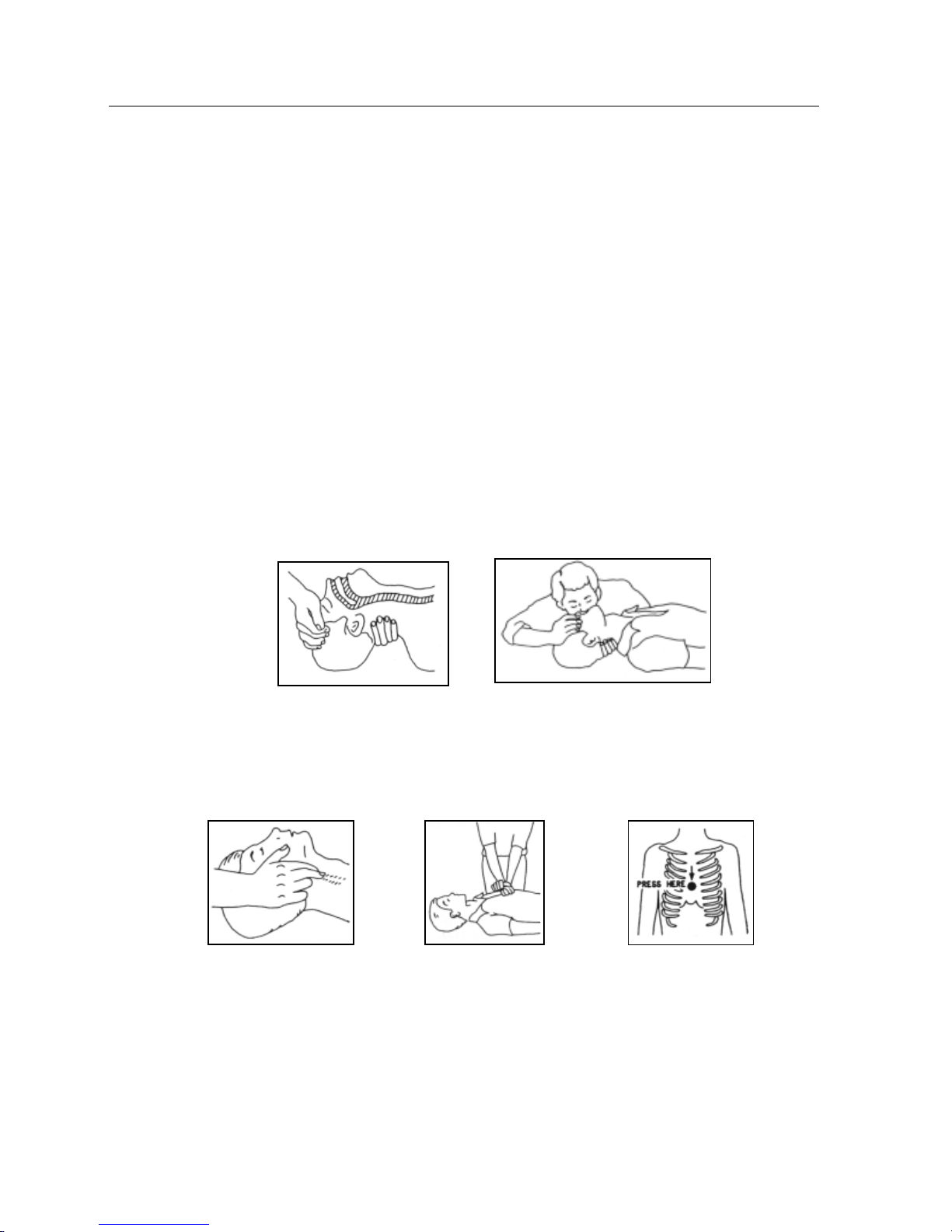
2.1.1 If the victim is not responsive
Follow the A-B-C's of basic life support
• Place victim flat on his back on a hard surface.
• Open airway: lift up neck, push forehead back (Fig. 3-1).
• Clear out mouth if necessary and observe for breathing
• If not breathing, begin artificial breathing (Figure 3-2): tilt head, pinch nostrils, make airtight
seal, four quick full breaths. Remember mouth to mouth resuscitation must be commenced as
soon as possible
Figure 3-1 Figure 3-2
• Check for pulse (Fig 3-3); if pulse is absent, begin artificial circulation
(Fig. 3-4) depressing sternum (Fig. 3-5)
Figure 3-3 Figure 3-4 Figure 3-5
• In case of only one rescuer, 15 compressions alternated to two breaths.
• If there are two rescuers, the rhythm shall be of one breath each 5 compressions.
• Do not interrupt the rhythm of compressions when the second person is giving breath.
• Call for medical assistance as soon as possible.
Page 5

Harris Micromax FM Exciter REV 1 01/12/2007
WARNING: Disconnect primary power prior to servicing
2.1.2 If victim is responsive
• Keep them warm
• Keep them as quiet as possible
• Loosen their clothing (a reclining position is recommended)
• Call for medical help as soon as possible
2.2 Treatment of electrical Burns
2.2.1 Extensive burned and broken skin
• Cover area with clean sheet or cloth
• Do not break blisters, remove tissue, remove adhered particles of clothing, or apply any
salve or ointment.
• Treat victim for shock as required.
• Arrange transportation to a hospital as quickly as possible.
• If arms or legs are affected keep them elevated
If medical help will not be available within an hour and the victim is conscious and not vomiting,
give him a weak solution of salt and soda: 1 level teaspoonful of salt and 1/2 level teaspoonful of
baking soda to each quart of water (neither hot or cold). Allow victim to sip slowly about 4
ounces (half a glass) over a period of 15 minutes. Discontinue fluid if vomiting occurs
DO NOT give alcohol
2.2.2 Less severe burns
• Apply cool (not ice cold) compresses using the cleansed available cloth article.
• Do not break blisters, remove tissue, remove adhered particles of clothing, or apply salve or
ointment.
• Apply clean dry dressing if necessary .
• Treat victim for shock as required.
• Arrange transportation to a hospital as quickly as possible
• If arms or legs are affected keep them elevated.
Page 6

WARNING: Disconnect primary power prior to servicing
Harris Micromax FM Exciter REV 1 01/12/2007
Page 7

Harris Micromax FM Exciter REV 1 01/12/2007
WARNING: Disconnect primary power prior to servicing
T ABLE OF CONTENTS
Page
SECTION 1 General Description
1.1 Introduction 1-1
1. 2 Equipment function 1-1
1.3 Physical description 1-1
1. 4 Electrical description 1-2
1. 5 Simplified block diagrams 1- 2
1.6 List of subsystems 1-2
SECTION 2 Installation
2.1 Introduction 2-1
2.2 Unpacking 2-1
2.3 Returns and exchanges 2-1
2.4 Installation 2-1
2.4.1 A/C power connection 2-1
2.4.2 RF output connection 2-2
2.4.3 Audio input connections 2-2
2.4.3.1 MPX (composite) audio input connection 2-3
2.4.3.2 Mono audio input connection 2-3
2.4.3.3 Left and right channel audio inputs 2-4
2.4.4 Remote I/O connector 2 - 5
2.4.5 Service connector 2-6
SECTION 3 Operation
3.1 Introduction 3-1
3.2 Turning on the exciter 3-1
3.3 Adjusting RF power output 3-2
3.4 Operating frequency selection 3-3
3.5 Adjusting modulation deviation level 3-4
3. 6 Front panel LCD display menu description 3-5
3.6.1 Operations menu 3-5
3.6.2 Power menu 3-6
3.6.3 Power amplifier menu 3-6
3.6.4 Miscellaneous menu 3-6
3.6.5 Versions menu 3-6
3.6.6 Channels menu 3-6
Page 8

WARNING: Disconnect primary power prior to servicing
Harris Micromax FM Exciter REV 1 01/12/2007
Page 9

Harris Micromax FM Exciter Installation REV1 01/12/2007
SECTION 2
Installation
2.1 Introduction
This section contains information on how to install the exciter and covers the following topics:
• Unpacking (2.2)
• Returns and Exchanges (2.3)
• Installation (2.4)
• A/C power connection (2.4.1)
• RF output connection (2.4.2)
• Audio input connections (2.4.3)
• Remote I/O connector (2.4.5)
• Service connector (2.4.5)
2.2 Unpacking
The unit is shipped in a cardboard box. The shipping box also contains the manual and the A/C power
cord. Open the box and perform a visual check to determine that there was no physical damage during
shipment. Note any damage on the bill of lading and retain shipping documents.
If the contents are incomplete or if the unit is damaged, contact the carrier and factory immediately .
Time limit to file damage claims with the carrier is 14 days.
2.3 Returns and exchanges
Damaged or undamaged equipment should not be returned without first obtaining return authorization
from factory . Factory will provide special shipping instructions and provide a RMA number to insure proper
handling. If you need to return the unit, contact the customer service department at factory and have your
model number and serial number available. Serial number is located on the rear panel.
2.4 Installation
Prior to installation, the manual should be carefully studied to get an overall understanding of the
system. This will facilitate proper installation and initial checkout.
W ARNING: Disconnect primary power prior to servicing
2-1
Page 10

Harris Micromax FM Exciter Installation REV1 01/12/2007
2.4.1 A/C Power connection
The Micromax operates on 80-260 Volts AC (50 or 60 Hz single phase)
Connect the AC power on rear panel.
(REAR PANEL VIEW)
Connect AC cord here
2.4.2 RF output connection
Connect an antenna or an RF load to the type BNC female RF output connector on the rear panel.
(REAR PANEL VIEW)
Connect RF Output to antenna here
2.4.3 Audio input connections
All program audio connections are on the rear panel. Micromax is designed to accept any one of the
three types of program audio inputs:
(1) MPX (composite)
(2) Mono
(3) Left and right channels (using the built-in stereo generator)
(4) AES/EBU with optional digital input card
W ARNING: Disconnect primary power prior to servicing
2-2
Page 11

Harris Micromax FM Exciter Installation REV1 01/12/2007
2.4.3.1 MPX (composite) audio input connection
Connect MPX (composite) audio input to BNC connector on rear panel. On the front panel LCD
display , go to SET menu and select mono (composite) from the audio mono/stereo selection (see section 3 of
manual on how to navigate the LCD display).
(REAR PANEL VIEW)
Connect MPX (composite) audio input here
2.4.3.2 Mono audio input connection
Connect Mono audio input to XLR connector on rear panel. On the front panel LCD display , go to SET
menu and select mono (composite) from the audio mono/stereo selection (see section 3 of manual on how to
navigate the LCD display).
(REAR PANEL VIEW)
Connect mono audio input here
W ARNING: Disconnect primary power prior to servicing
2-3
Page 12

Harris Micromax FM Exciter Installation REV1 01/12/2007
2.4.3.3 Left and right channel audio inputs (using the built-in stereo generator)
Connect left and right channel audio inputs to XLR connectors on rear panel. On the front panel LCD
display , go to SET menu and select stereo from the audio mono/stereo selection (see section 3 of manual on
how to navigate the LCD display). This will activate the built-in stereo generator and turn on the 19 kHz stereo
pilot tone at 10% injection.
(REAR PANEL VIEW)
Connect left audio input here
Connect right audio input here
W ARNING: Disconnect primary power prior to servicing
2-4
Page 13

Harris Micromax FM Exciter Installation REV1 01/12/2007
2.4.4 Remote I/O connector (using provided DB15 interface jumper)
Remote control and monitoring of the transmitter is available through a DB15 connector on the rear
panel. Following describes the function of each pin on the remote I/O connector using the provided DB15
interface jumper.
9
1
Type: DB15 female (cable end)
PIN FUNCTION TYPE DESCRIPTION
1 GROUND GROUND
2 FWD POWER OUT analog 0 to 4V Adjustable
3 RFL POWER OUT analog 0 to 4V
4 PA V OUT analog 0 to 4V
5 PA I OUT analog 0 to 4V
6 FAULT OUT digital Output low in Fault condition (adjustable by PgD setting)
7 N/C No connection
8 EXCITER APC INPUT Ext. signal, for power limitation (set by FWD AGC pot)
9 RF MUTE INPUT Short to ground to operate (tied to 14)
10 INTLK COM OUT Relay contacts COM
11 INTLK NC OUT Relay contacts NC
12 INTLK NO OUT Relay contacts NO
13 EXC ON CMD INPUT digital Low pulse (500 ms) enables RF*
14 RF MUTE INPUT Short to ground to operate (tied to 9)
15 EXC OFF CMD INPUT digital Low pulse (500 ms) disables RF
* RF UNMUTES IN A SLOW RAMP UP
W ARNING: Disconnect primary power prior to servicing
2-5
Page 14

Harris Micromax FM Exciter Installation REV1 01/12/2007
2.4.5 Service connector
Service connector is used to interface with a computer RS232 port. It can also be used to remotely
set operating frequency and RF power level of the exciter (see attachment 1 on page 3-7).
Following describes the function of each pin on this connector:
6
1
Type: DB9 female
1NC
2 TX_D
3 RX_D
4 Internally connected with 6
5 GND
6 Internally connected with 4
7 Internally connected with 8
8 Internally connected with 7
9NC
W ARNING: Disconnect primary power prior to servicing
2-6
Page 15

Harris Micromax FM Exciter System Overview REV1 01/12/2007
SECTION 1
System Overview
1.1 Introduction
This section contains system overview information and covers the following topics:
• Equipment Function (1.2)
• Physical Description (1.3)
• System Front and Rear Views (1.4)
• Simplified Block Diagrams (1.5)
• List of Subsystems (1.6)
• Technical and Mechanical Specifications (Tables 1.1)
1.2 Equipment function
The Harris Micromax is a 30 W att FM exciter designed to operate in the 88-108 MHz range in 10
kHz steps. The RF power is adjustable continuously from 0-100% of rated power . It is designed to handle
MPX (composite), mono and left/right audio inputs with the built-in stereo generator. The internal stereo
generator can be turned on or off in the field.
In addition, an optional AES/EBU module is available for digital audio input capability .
In keeping with the design philosophy of modularity and maintainability , Micromax uses easily removable
and serviceable subsystems. List of subsystems is outlined in section 1.6.
1.3 Physical description
Micromax is electrically and mechanically modular in design. The entire system is contained in a 19”
rack that is 1.75” high. All subsystems are assembled with removable connectors to allow for easy servicing
and replacement.
The front panel contains an LCD display for metering and control, a menu navigation and selection
knob, on/off switch and status LEDs.
Rear panel contains AC input block, RF connectors, audio connectors, remote control and monitoring
connectors.
See Figure 1-1 for front and rear views of the Micromax FM exciter.
WARNING: Disconnect primary power prior to servicing
1-1
Page 16

Harris Micromax FM Exciter System Overview REV1 01/12/2007
1.4 Electrical description
Micromax is a self contained broadband FM exciter . The frequency of operation and RF power level
are selectable from the front panel. A microprocessor controller monitors all operating parameters and
automatically lowers RF output in case of high VSWR or temperature.
Unit is powered by a high efficiency , universal AC input (80-260V AC) switching power supply . The
RF output module is totally broadband across the FM band and is capable of delivering RF output power of
up to 30 W atts.
T echnical specifications of the Micromax is shown in T able 1-1.
1.5 Simplified block diagrams
Micromax is composed of modular subsystems that are easily removable and serviceable.
A simplified block diagram of how all the subsystems are interconnected is shown in Figure 1-3.
Location of subsystems is shown in Figure 1-4.
1.6 List of subsystems
Micromax is composed of the following subsystems:
1. Power supply
2. Main card
3. Controller card
4. RF Power amplifier
5. AES/EBU card (optional)
WARNING: Disconnect primary power prior to servicing
1-2
Page 17

Harris Micromax FM Exciter System Overview REV1 01/12/2007
WARNING: Disconnect primary power prior to servicing
FIGURE 1-1
Front and Rear Views
1-3
Page 18

Harris Micromax FM Exciter System Overview REV1 01/12/2007
TABLE 1-1
Technical Specifications
Panel size 483 mm (19”) x 44 mm (1.75”) (1U)
Depth 286 mm (1 1.25”)
Weight 6 Kg (13.2 lbs)
Operating T emperature -10 °C ÷ 50 °C
Electrical specifications
General
RF output power 0 to 30 Watts, adjustable
RF output connector "N"-type
RF output impedance 50 Ohm
Frequency range 87.5 MHz ÷ 108 MHz
Frequency setting Direct software programming
Frequency stability ±1ppm from -10°C to 50°C
Modulation type Direct carrier modulation
Spurious and Harmonics suppression Meets or exceeds FCC and CCIR
standards (typical -75 dBc)
Modulation capability Meets or exceeds FCC and CCIR
standards (typical 240khz MPX/
Composite/mono, 210 KHz Stereo)
Asyncronous residual AM < -60 dB wrt. 100% peak AM
Syncronous residual AM < -50 dB wrt. 100% peak AM, with
75 kHz deviation @ 400Hz
A/C power supply ≅ 80 V ÷ 260 V , full-range
D/C power supply 28 V
Power consumption 120 Watts
Input
Left, right, AES/EBU and mono Input T ype: XLR female
Composite (MPX) input Type: BNC, unbalanced
Input impedance balanced input: 600 or 10 k Ohm
Input level -13 dBm ÷ +13 dBm, continuosly
Preemphasis Selectable: 0
WARNING: Disconnect primary power prior to servicing
balanced or unbalanced
selectable, unbalanced input: 50 or
10 k Ohm selectable
adjustable
50 us (CCIR)
75 us (FCC)
1-4
Page 19

Harris Micromax FM Exciter System Overview REV1 01/12/2007
TABLE 1-1 (continued)
Technical Specifications
SCA/RDS input 2 BNC unbal
SCA/RDS input impedance 10 kOhm
SCA/RDS input level -20 dBm ÷ +13 dBm for 2.0 kHz
continuosly adjustable
SCA/RDS amplitude/frequency response ± 0.2 dB, 40 kHz to 100 kHz
Output
RF Ouput “BNC”-type, 50 Ohm
RF T est BNC connector, --13 dBm +/-6 dB
50 Ohm
19 kHz pilot tone output BNC connector , 1 Vpp
minimum load 4.7 kOhm
Composite or Mono operation
S/N > 70dB wrt. 75 kHz, measured in the band 30 Hz
÷ 20 kHz, 50 us deemph., RMS detect
Amplitude frequency response ± 0.5 dB, 20Hz ÷ 15Khz
T otal harmonic distortion (THD) < 0.08%
MPX operation
composite S/N > 70 dB wrt. 75 kHz, measured in the band 30 Hz
÷ 20 kHz, 50 us deemph., RMS detect
MPX amplitude frequency response ± 0.3 dB, 30 Hz ÷ 53 KHz
± 0.3 dB, 53 KHz ÷ 100 KHz
MPX total harmonic distortion (THD) < 0.08 %
Stereo separation > 55 dB (typ. 60dB, with external stereo generator)
Stereo operation
S/N FM S tereo > 70 dB wrt. 75 kHz, measured on decoded
channels, in the band 30 Hz ÷ 20 KHz,
50 us deemph, RMS detector
Audio frequency response ± 0.5 dB, 30 Hz ÷ 15 KHz
T otal harmonic distortion (THD) ≤ 0.08 %
Stereo separation > 50 dB
Connections
Interlock connector BNC, inhibits RF power output when shorted to
ground
Service (serial) interface DB9 female RS232
Remote DB15 female
WARNING: Disconnect primary power prior to servicing
1-5
Page 20

Harris Micromax FM Exciter System Overview REV1 01/12/2007
ANTENNA
30W RF P A
AUDIO IN
MAIN CARD
AES/EBU CARD
(OPTIONAL)
POWER SUPPL Y
CONTROLLER
WARNING: Disconnect primary power prior to servicing
FIGURE 1-3
Block Diagram
1-6
Page 21

Harris Micromax FM Exciter System Overview REV1 01/12/2007
30W RF P A
POWER SUPPL Y
MAIN CARD
WARNING: Disconnect primary power prior to servicing
CONTROLLER
FIGURE 1-4
Location of Subsystems
1-7
Page 22

Harris Micromax FM Exciter System Overview REV1 01/12/2007
WARNING: Disconnect primary power prior to servicing
1-8
Page 23

Harris Micromax FM Exciter Operation REV1 01/12/2007
SECTION 3
Operation
3.1 Introduction
This section of the manual contains information on how to operate the exciter and covers the following
topics:
• Turning on the transmitter (3.2)
• Adjusting RF power output (3.3)
• Operating frequency selection (3.4)
• Adjusting modulation deviation level (3.5)
• Front panel LCD display menu description (3.6)
3.2 T urning on the unit
Prior to turning on the exciter, make sure that the unit is installed as outlined in Section 2 of this manual.
Turn on the exciter using the on/off switch on the front panel.
Turn on/off here
WARNING: Disconnect primary power prior to servicing
3-1
Page 24

Harris Micromax FM Exciter Operation REV1 01/12/2007
3.3 Adjusting RF power output
In default mode, front LCD screen displays forward power output and modulation level as follows:
T o adjust power, press the KNOB for approximately 2 seconds until the display changes to SET
mode as shown below . When the display changes to the SET menu, release the KNOB. Then turn the knob
to raise and lower the RF output power to desired level.
WARNING: Disconnect primary power prior to servicing
3-2
Page 25

Harris Micromax FM Exciter Operation REV1 01/12/2007
3.4 Operating frequency selection
T o select operating frequency , first press the KNOB to go to SELECTION menu as shown below .
Then, from this menu, turn KNOB to move the cursor to SET menu and then press knob to enter SET menu.
cursor
This will show the following screen (SET menu). T urn knob so the arrow is next to F1 (frequency).
WARNING: Disconnect primary power prior to servicing
3-3
Page 26

Harris Micromax FM Exciter Operation REV1 01/12/2007
Press the KNOB to enter frequency setup. Three arrows will appear to the left of the frequency
display as shown below . Then use the knob to change the operating frequency . When the desired frequency
is displayed on the screen, press the knob to change to the new frequency .
3.5 Adjusting modulation deviation level
Modulation level adjustments are on the rear panel next to each audio input. Adjust modulation
deviation levels using a small screwdriver as shown below. On front panel, 100% modulation is indicated
when the bar graph on the default menu is equal to the 5 vertical dots on display as shown below.
(REAR PANEL VIEW)
Right channel level adjust
Mono or left channel level adjust
MPX (composite) level adjust
100% modulation
WARNING: Disconnect primary power prior to servicing
3-4
Page 27

Harris Micromax FM Exciter Operation REV1 01/12/2007
3.6 Front panel LCD display menu description
Front panel LCD display displays all operating parameters of the Micromax FM Exciter. This menu can
be navigated using the knob located next to the LCD display. Below is a map of the menus available on the
display.
Descriptions of the power adjustment (menu 2) and frequency setting (menu 7) menus are explained in
sections 3.3 and 3.4.
WARNING: Disconnect primary power prior to servicing
3-5
Page 28

Harris Micromax FM Exciter Operation REV1 01/12/2007
3.6.1 Operations menu (menu 4)
This menu contains the control function to turn on and off the exciter, ability to change the
modulation meter on the LCD display to 10X modulation level and the ability to set PgD and PgR levels.
PgD and PgR are threshold levels that provide a logic high or low state on the telemetry connector. PgD is
a threshold level for the forward power level and PgR is a threshold level for reflected power. For example
if PgD is set at 50%, logic level on pin 7 will change state (high or low depending on jumper settings on the
telemetry board) when forward power is above 15 Watts.
3.6.2 Power menu (menu 5)
This menu indicates forward and reflected power of the exciter.
3.6.3 Power amplifier (menu 6)
This menu indicates the PA voltage, PA current, PA efficiency and PA temperature.
3.6.4 Miscellaneous menu (menu 8)
This menu allows to change the address of the exciter’s IIC bus address.
3.6.5 Versions menu (menu 9)
This menu indicates the version and the release of the software used in the exciter.
3.6.6 Channels menu (menu 10)
This menu indicates the modulation level of the left and right channel audio levels when the exciter is
operated in the stereo mode using the internal stereo generator.
WARNING: Disconnect primary power prior to servicing
3-6
Page 29

Harris Micromax FM Exciter Operation REV1 01/12/2007
Attachment 1
How to remotely program operating frequency and RF power level using Windows
Hyperterminal
1) Turn Exciter on into proper load
2) Open up Windows Hyperterminal on the computer
3) Select Connect using COMx (your serial or RS-232 port)
4) Select BPS: 19200 (2400/4800/9600 will also work), Data Bits: 8, Parity: None, Stop
Bits: 1
Flow Control: none (without handshake)
5) Connect computer comport to RS232 port on exciter
6) FOR FREQ enter FR*98.000 (enter freq in format xxx.xxx)
FOR POWER LEVEL enter PWR075% (100% = 30 Watts)
7) If it is received correctly, the exciter will give an echo to the computer.
WARNING: Disconnect primary power prior to servicing
3-7
Page 30

Harris Micromax FM Exciter Operation REV1 01/12/2007
WARNING: Disconnect primary power prior to servicing
3-8
 Loading...