

Page 1

1-877-OPENSKY
WINST-0009 Rev – WIRELESS SYSTEM BUSINESS UNIT
SUBJECT:
O
VERVIEW
This document describes the procedure for installing
the M/A-COM OpenSky
Tactical Network (V-TAC) in a vehicle, such as an
automobi le, tr uc k, or v an. This is a g eneral guide onl y,
and assum es th at the install ation will be performed by
a professional radio installer.
D
ISCLAIMER
THE INSTALLATION INSTRUCTIONS PROVIDED IN THIS MANUAL ARE FOR
REFERENCE, AND DO NOT CREATE A WARRANTY OF ANY KIND AS TO THE
FUNCTIONALITY OF THE INSTALLED PRODUCT. THE ONLY WARRANTIES
THAT APPLY TO THIS PRODUCT ARE THOSE SET FORTH IN THE SALES
AGREEMENT.
M/A-COM INC. RECOMMENDS THAT BUYER USE ONLY A M/A-COM
AU THORI ZED REPRESENTATIVE TO INSTALL THIS PRODUCT.
THE WARRANTIES PROVIDED TO BUYER UNDER THE TERMS OF SALE
SHALL BE NULL AND VOID IF THIS PRODUCT IS INSTALLED OR SERVICED
IMPROPERLY, AND M/A-C OM SHALL HAVE NO FURTHER OBLIGATION TO THE
BUYER FOR ANY DAMAGE CA USED T O THE PRODUCT OR TO ANY PERSON
OR PERSONAL PROPERTY.
M-803 VTAC Installation Instructions
Model VR-803 Vehicular
®
DATE:
February 19, 2002
1 of 19
Page
M
ATERIALS
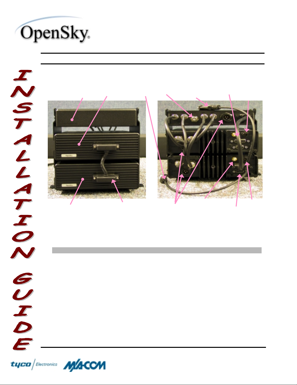
There are three main components to the VR-803 V-TAC: the Full-Duplex Mobile
Radio Unit (MRU ); the V ehic ular Repeat er Base U nit (V RB); a nd the RF C ombiner.
The V-TA C i s desi g ned to mo unt o n t he f loo r or on a tray i n the tr unk o r unoccupi ed
section of a vehicle. The V-TAC is designed to be operated with an externallymounted a ntenna. The Installatio n Kit (M/A-COM Part #MA MROS0019) needed to
install t he V-T A C i s descri be d be low. The V-TAC is i ntended to be us ed with a CH 103 Control Head with Installation Kit, sold separatel y.
Table I lists the accessories that are included in the kit. Table II lists additional
options and accesso ries that m ay be purchas ed separate ly. (Note: T he Installation
Kit does not include an antenna. An antenna must be purchased separately, and the
V-TAC may not be installed unless an antenna is to be installed at the same time.)
COPYRIGHT ©2002 Pri nte d in U.S. A.
M/A-COM
1011 Pawtucket Boulevard
Lowell, MA 01853
1-877-OPEN S KY
(1-877-673-6759)
Page 2

1-877-OPENSKY
WINST-0009 Rev – WIRELESS SYSTEM BUSINESS UNIT
SUBJECT:
Item Qty Part Nu mber Description
1 1 MAMROS0044 Base Bracket Kit
2 2 MAMROS0046 Extension Bracket Kit
3 1 MAMROS0068-0003 Fuse Kit, 3A
4 2 MAMROS0068-0015 Fuse Kit, 15A
5 3 MAMROS0051 DC Power Cable, M-803 (20 ft)
6 1 MAMROS0052 Multi-Cable Assembly
7 1 MAMROS0054 V-TAC Control Interface Assembly
8 1 MAMROS0078-TMB12 RF Cable, TNC to Mini-UHF, Blue
9 1 MAMROS0078-TMG12 RF Cable, TNC to Mini-UHF, Green
10 1 MAMROS0078-TTR12 RF Cable, TNC to TNC, Red
11 1 MAMROS0078-TTX12 RF Cable, TNC to TNC, Yellow
12 1 MAMROS0066 CAN Terminator, 3-Pin
13 1 MAMROS0060 Antenna Connector, TNC
M-803 VTAC Installation Instructions
T able I – Install at ion Kit Items
Table II - Additional V-TAC Options and Accessories
DATE:
February 19, 2002
2 of 19
Page
Part Nu mber Description
(TBD) GPS Upgrade Option
MAMROS0023 GPS Antenna Kit, Show/No-Show/Magnet Mount
MAMROS0033 Antenna Kit, Unity Gain, Rooftop
MAMROS0031 Antenna Kit, 3dB, Rooftop
MAMROS0024 Antenna Kit, Elevated 3dB, Trunk Mount
MAMROS0039 SMR/GPS Antenna Kit, 3dB, Rooftop
MAMROS0026 SMR/GPS Antenna Kit, Elevated 3dB, Trunk Mount
MAMROS0042 SMR/GPS Antenna Kit, Elevated 3dB, Mirror Mount
MAMROS0055 RS-232 Serial Computer Cable (6 ft)
I
NSTRUCTIONS
Upon removing all items from the box and verifying that all have been included,
proceed with t he fo llowing steps to i nstall the VR- 803 V-T AC. Ref er to Figure 1 f o r
location of connectors on the V-TAC.
Mounting of the V-TAC and Antenna in ways other than those
described below m ay advers ely aff ect perf ormance , violate FCC
rules on RF Exposure, and even damage the V-TAC.
IMPORTANT
COPYRIGHT ©2002 Pri nte d in U.S. A.
M/A-COM
1011 Pawtucket Boulevard
Lowell, MA 01853
1-877-OPEN S KY
(1-877-673-6759)
Page 3
1-877-OPENSKY
WINST-0009 Rev – WIRELESS SYSTEM BUSINESS UNIT
SUBJECT:
M-803 VTAC Installation Instructions
Speaker
RF
VRB
Connection
(Disabled)
Antenna
Port
(TNC)
GPS Data
Connection
(Optional)
DATE:
February 19, 2002
Multi-Cable
Assembly
3 of 19
Page
CAN Port
(Terminated)
MRU
V-T AC Control
Interface Assembly
D.C. Power
Connections
Figure 1 - Front and Rear Views of VR-803 V-TAC
Actions Notes
1. Plan the mounting locations of all
components (V-TAC, Antenna, and
Cables) and determine t he routes for
all wiring and cables.
♦ Determine the customer’s pr ef er ences, if
any, for location of components. Comply with
these preferences insofar as t hey are
consistent with safety, manufacturer
specificatio ns, and generally accept ed
professional practices.
♦ Make cert ain that drilling holes or insert i ng
scr e ws will not da mage or interfere w it h any
existing vehicle compo nents or w ir ing.
♦ Follow all manufacturer r equir eme nts a nd
guidelines for t he locatio n of components.
GPS Antenna
(SMA - Optio na l)
CAN Port
RS-232
Se ri al Port
COPYRIGHT ©2002 Pri nte d in U.S. A.
M/A-COM
1011 Pawtucket Boulevard
Lowell, MA 01853
1-877-OPEN S KY
(1-877-673-6759)
Page 4
1-877-OPENSKY
WINST-0009 Rev – WIRELESS SYSTEM BUSINESS UNIT
SUBJECT:
M-803 VTAC Installation Instructions
Actions Notes
2. Mount the bracket in the interior of t he
vehicle.
The VR-803 V-TAC
must be kept away
from sources of heat.
Adequate ventil ation
WARNING
MRU and VRB. The V-TAC
reduces i ts RF output power
when its ambient temperature
exceeds +60ºC.
must be provi ded to
the rear fins of the
DATE:
♦ As an assembled unit, the V-TAC weighs
over 20 lbs. It is unadvisable for t he V-TAC
to be hung from a surface; rather, the V-TAC
is best mounted onto a firm, f lat s urface.
♦ Mount the Base Bracket from the Base
Bracket Kit (Item 1) on top of the floor of the
trunk according to t he available space i n the
vehicle or on the surface of a tr unk tray.
♦ Screws f or mounting the bracket are not
included, as all installations are different, but
at least 6 screw s are required. Steel #10
screws are recomme nded.
♦ Screws for mounting the MRU into the Base
Bracket ar e included.
♦ The Bracket must be firmly held to the
surface in order t o pr event unreasonable
vibratio n from damaging t he V-TAC or
connectio ns from loose ning.
February 19, 2002
4 of 19
Page
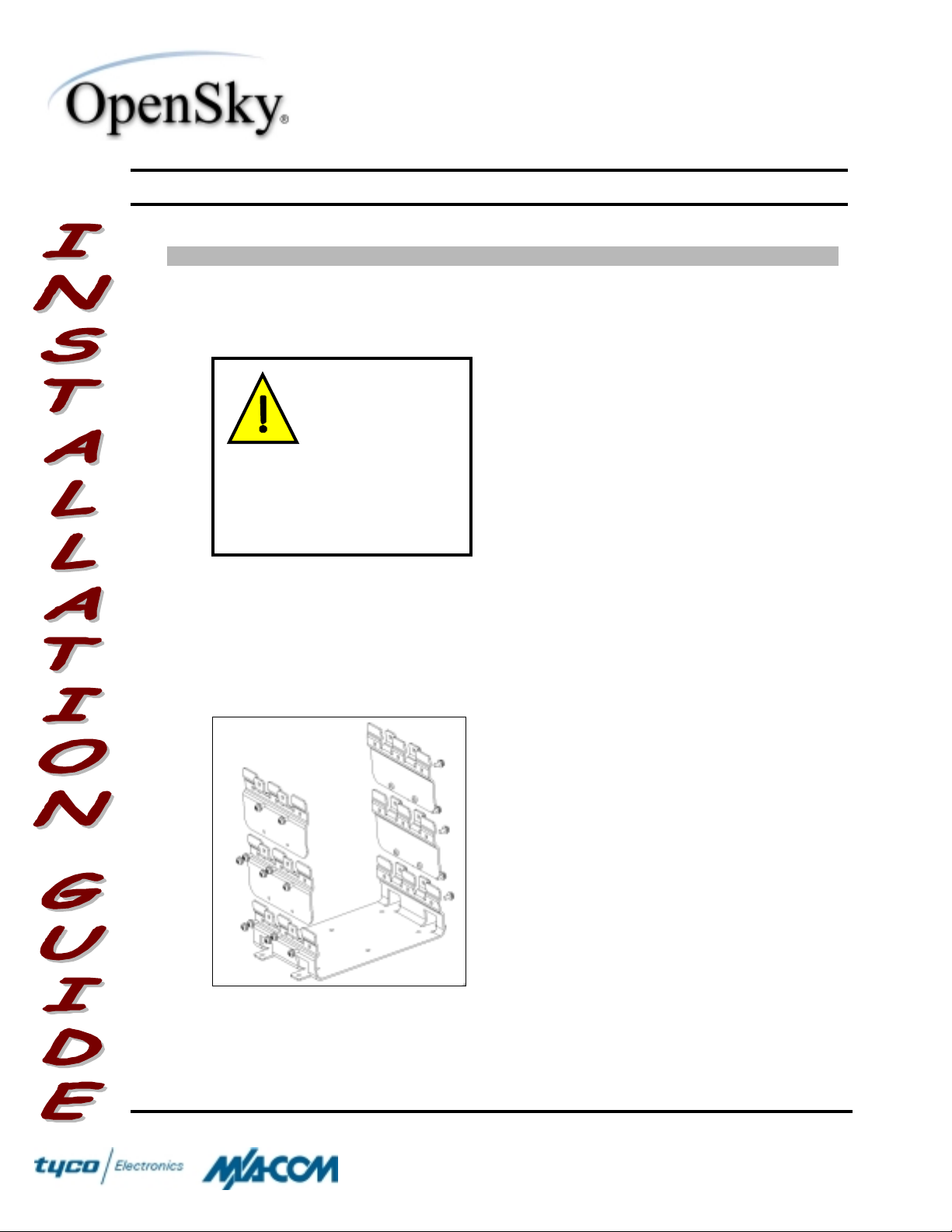
3. Create a support brac ket by installing
the Extension Brackets onto the Base
Bracket.
4. Mount the individual components into
the support brack et .
♦ Install two Extension Brackets from the
Extension Bracket Kit (Item 2), one on either
side, onto the Base Bracket using 2 screw s
from the kit. Tighten with a screwdriver until
the Extension Bracket is firm and flush to the
Base Bracket.
♦ The Exte nsio n Bracket can only be installed
onto the Base Bracket one way. See the
exploded view on the left for proper
alignment.
♦ Install the other two Extension Brackets, one
on eit her side, onto the Extension Brackets
just assembled.
♦ The Exte nsio n Bracket can only be installed
onto another Extension Bracket one way.
See the exploded view on the left f or proper
alignment.
♦ Tighten with a screwdriver until the Extension
Bracket is firm and flush.
♦ It is easy to mistake the VRB for the MRU,
because they are manufactured into the
same chassis. There are t wo features,
COPYRIGHT ©2002 Pri nte d in U.S. A.
M/A-COM
1011 Pawtucket Boulevard
Lowell, MA 01853
1-877-OPEN S KY
(1-877-673-6759)
Page 5

1-877-OPENSKY
WINST-0009 Rev – WIRELESS SYSTEM BUSINESS UNIT
SUBJECT:
M-803 VTAC Installation Instructions
Actions Notes
NOTE
ance of the Radio is based upon
proper m ounting techni ques. An
impr operl y m ounted V-TAC may
experienc e degr adation in the
quali ty of communication with
the OpenSky® network.
Optimal perform-
DATE:
however, to distinguish the two units:
! Each unit has a different product label.
! The MRU has a red and green color-
coding for the antenna ports, while the
VRB has a yellow and blue color-coding.
! See the picture on the left for locations of
the labels.
♦ Install the MRU into the lowermost bracket
spot using 6 screws (It em 10), 3 per side,
and tighten with a screwdr iver until the
bracket is firm and flush to the surface of the
MRU.
♦ Install the VRB into the middle bracket spot
using 6 screws (I t em 10), 3 per side. Do not
tighten these scr ews until the VTAC
Cont rol Inte rfac e A s s emb ly is installed (Step
7).
♦ Install the RF Combiner into the uppermost
bracket s lot using 4 screw s (Item 10), 2 per
side, and tighten with a screw dr iver until the
bracket is firm and flush.
February 19, 2002
5 of 19
Page
5. The CAN Port needs to be t erminated
properly.
NOTE
must be installed and connected
to the MRU before power to the
V-TAC is appl i ed.
6. The control connectio n betw een the
MRU and RF Combiner needs to be
made.
COPYRIGHT ©2002 Pri nte d in U.S. A.
The Control Head
♦ Install the CAN Terminator (Item 12) onto the
smaller 3-pin connect or at the rear of the
VRB by aligning the connector appr opr iat ely,
pushing, and tw ist ing the outer housing
clockwise until it st ops.
♦ The CAN Port of the MRU is where t he CA N
Cable of the CH-103 Control Head is to be
connected. See the Installatio n G uide for t he
CH-103 for more det ails.
♦ Install the male15-pi n, 2-r ow c onnector of the
Multi-Cable Assembly (Item 6) onto the
female mate at the rear of the MRU.
! Secure the connection by screwing the
jackscrews until they are firmly in place.
Do not over- tighte n.
♦ Install the male15-pi n, 3-r ow c onnector of the
Multi-Cable Assembly onto the female mate
at the rear of the RF Combiner.
M/A-COM
1011 Pawtucket Boulevard
Lowell, MA 01853
1-877-OPEN S KY
(1-877-673-6759)
Page 6
1-877-OPENSKY
WINST-0009 Rev – WIRELESS SYSTEM BUSINESS UNIT
SUBJECT:
M-803 VTAC Installation Instructions
Actions Notes
NOTE
Assembly ( Item 6) suppor ts
multi pl e confi gur ati ons of the M803 Radio Product Fami l y . For
the V-TAC configurati on, the 2pin speaker connecti on m ust be
left unconnected. Instead, the
speaker connection m us t come
from the CH-103 Control Head.
The speaker output from the
Multi-Cable Assembly is
disabl ed i n the V-TAC.
7. The control connectio n betw een the
MRU and VRB needs to be made.
WARNING
For this type of ass em bly, slight
squeezing pr essur e m us t be
appli ed between the connectors to
reduce the strain when i nstalled
and to ensure the screws do not
cross-thread.
The Multi-Cable
Early ver sions of this
assembl y have been
constructed with a
cable joining the two
multi - pin connectors
(shown in Fi gur e 1).
DATE:
! Secure the connection by screwing the
jackscrews until they are firmly in place.
Do not over- tighte n.
♦ The Multi-Cable Asse mbly s upports an
interface for optional GPS in the V-TAC. The
9-pin female connectio n in the Multi-Cabl e
Assembly can be connected through an RS232 Serial cable to a COM Port of a
computer to access the GPS’s NMEA outp ut.
! To connect this interface, mate the male
9-pin connector of the optional serial cable
to the female connector of the Multi-Cable
Assembly and tighten the jackscrews until
firm.
! Industry software to process GPS
information through this interface is not
supported by M/A- CO M .
♦ Inst a ll the V-T AC Contr ol Inter face As s embly
(Item 7) onto the connectors on the front
panels of the MRU and VRB.
! Screw the four screws of the Interface
Assembly with a screwdriver until they
stop. Do not over-tighten.
! The mounting screws of the VRB were
left loose in order to accommodate
proper alignment of t he Interface
Assembly.
! Tighten the 6 mounting scr ew s of the
VRB with a screwdriver until the bracket
is firm and flush to the surface of the
VRB.
February 19, 2002
6 of 19
Page
8. The RF connections among all three
units must be made.
Improper i nstal lation
of the RF Cables may
lead not only to poor
radio perfor m anc e,
WARNING
Antenna Mounting Configurations
COPYRIGHT ©2002 Pri nte d in U.S. A.
but also to harmf ul
exposure. See
♦ The RF Cables are color-coded for pr oper
assembly. Assemble t hem as follows:
! Connect the Mini-UHF end of the blue-
coded RF Cable (It em 8) to the MiniUHF connector on the VRB, and
connect the TNC end to the blue-coded
connector on the RF Combiner.
! Connect the Mini-UHF e nd of the green-
.
coded RF Cable (It em 9) to the Mini-
1011 Pawtucket Boulevard
Lowell, MA 01853
1-877-OPEN S KY
(1-877-673-6759)
M/A-COM
Page 7
1-877-OPENSKY
WINST-0009 Rev – WIRELESS SYSTEM BUSINESS UNIT
SUBJECT:
M-803 VTAC Installation Instructions
Actions Notes
To prevent RF
leakage and ensur e
peak perfor m ance,
make sure that the
WARNING
but not too tight that damage
occurs.
9. Mount the Antenna at a suitable
location on the vehicle, and route t he
Antenna Cable inside the vehicle for
connectio n to the Radio.
IMPORTANT
Testing into a Dummy Load
further i nformation.
TNC and Mini- UHF
connectors are tight,
Do not permanently
connect the antenna
to the V-TAC until
satisfactory testing
into a dummy load is
completed. Refer to
for
DATE:
UHF connector on the MRU, and
connect the TNC end to the greencoded connector on the RF Combiner.
! Connect one of the TNC ends of the red-
coded RF Cable (It em 10) to the TNC
connector on the MRU, and connect t he
other end to the red-coded c onnector on
the RF Combiner.
! Connect one of the TNC ends of the
yellow-coded RF Cable (I tem 11) to the
TNC connector on the VRB, and
connect the other end to the yellowcoded connector on the RF Combiner.
! Use a pair of pliers to snug the
connections. Do not over-tighten.
♦ The Antenna is not included in the kit, as
several types of ante nnas can be used with
the V-TAC.
♦ The Antenna must be i nstalled bef or e
completion of the V-TAC installation.
♦ The optimal type of antenna to use is the
rooftop mount. For best performance, the
rooft op mount should be placed in the direct
center of the roof of t he vehicle.
♦ Various mounting configurations are off er ed
for antennas available t hro ugh M/A-CO M .
Check with OpenSky® Customer Service for
more information.
♦ Refer to
for requirements necessary to follow when
selecting the proper mounti ng area for t he
antenna. Also, refer to the antenna
manufacturer’s mounting and testing
instructions included in the Antenna
Assembly kit for installation guidance once
the mounting area is deter mined.
♦ Route the cable from the Antenna to the rear
of the V-TAC out of the way of casual
contact.
♦ A Mini-UHF connector is ge nerally incl uded
with the Antenna Kit, but connection to the V-
Antenna Mounting Configur ations
February 19, 2002
7 of 19
Page
COPYRIGHT ©2002 Pri nte d in U.S. A.
M/A-COM
1011 Pawtucket Boulevard
Lowell, MA 01853
1-877-OPEN S KY
(1-877-673-6759)
Page 8

1-877-OPENSKY
WINST-0009 Rev – WIRELESS SYSTEM BUSINESS UNIT
SUBJECT:
M-803 VTAC Installation Instructions
Actions Notes
To prevent RF
leakage and ensur e
peak perfor m ance,
make sure that the
WARNING
tig h t th at damage occurs.
10. If an optional GPS unit is included in
the V-TAC, the GPS Antenna needs
to be connected.
WARNING
tig h t th at damage occurs.
TNC connector i s
tight, but not too
To prevent RF
leakage and ensur e
peak perfor m ance,
make sure that the
SMA connector is
tight, but not too
DATE:
TAC must be TNC. Therefore, included i n the
Installation Kit is a TNC Connector (Item 13).
♦ Crimp the TNC Connector onto the Ante nna
cable by following the directions included in
the Antenna Kit.
♦ Screw the TNC Connector of the Antenna
Cable to the TNC Antenna Port connectio n
(coded wit h the color white) of t he RF
Combiner, tightening until finger-tight.
♦ This will be a t e mpo rary c on nectio n u ntil the
V-TAC and Antenna can be tested after the
V-TAC installation is complete. The antenna
needs to be connected in case of accidental
tranmission of the V-TAC occurs.
♦ Screw t he SMA plug of the GPS Antenna
cable to the SMA receptacle on the rear of
the MRU, tightening unt il finger-tight.
♦ Route the remaining cable out of t he way of
casual contact.
♦ Various mounting configurations are off er ed
for GPS antennas available t hro ugh M/ACOM. Check with OpenSky® Customer
Service for more information.
♦ The GPS Antenna must be kept at least 6
inches from any other antenna mo unted on
the vehicle and have at least 6 inches of
ground plane beneat h it.
February 19, 2002
8 of 19
Page
11. Prepar e f or connecting the power to
t he V-TAC through t he vehicle ’ s
firewall.
12. The Fuses for t he individ ual units i n
the V-TAC must be installed in-line
with raw batter y voltage.
COPYRIGHT ©2002 Pri nte d in U.S. A.
♦ Plan the cable route carefully, using an
existing access hole through the engi ne
fir e wall if p o s s ible . Alternati vely, d r ill a new
hole approximately 3/8" in diameter and
install a rubber grommet to pr otect the cable.
♦ Strip one end of the wire included in the 3A
Fuse Kit (Item 3) and crimp a terminal lug
(not included) ont o it whic h w ill m ount direct ly
to the positive battery post.
♦ Cut the wire to a length of about 6 inc hes
and strip the end to a length indicated by the
gauge on the fuse holder.
M/A-COM
1011 Pawtucket Boulevard
Lowell, MA 01853
1-877-OPEN S KY
(1-877-673-6759)
Page 9
1-877-OPENSKY
WINST-0009 Rev – WIRELESS SYSTEM BUSINESS UNIT
SUBJECT:
M-803 VTAC Installation Instructions
Actions Notes
The Fuse must not
be install ed in the
Fuse Holder until all
wiring is complete .
IMPORTANT
powering up prem atur el y and
causing an i n-rush of cur r ent that
could l ead to shorti ng of the
battery, sparki ng, or even fire.
This will prevent the
V-TAC f r o m
DATE:
♦ Open the fuse holder and remove the fuse.
♦ Insert the stripped wire into the fuse holder
and push out the holder socket.
♦ Crimp the socket onto the wire at the crimp
end and pull the wire so that the socket seats
back into the holder.
♦ Use heat-shrink tubing to protect the
connection from foreign materials.
♦ Connect the remaining wire in a similar
fashion to the other end of the fuse holder.
♦ Connect the terminal to the vehicle’s battery
in the engine compartment.
♦ Mark or label the wire to indicate that the in-
line fuse is 3 Amps.
♦ Route the wire at the other end through a
wire loom and pass it through the firewall,
using a grommet to ensure that the wire is
not damaged.
♦ Repeat the proced ure above for t he two 15A
fuse kits (Item 4). Mark or label these wires
to indicate the in-line fuses are 15 Amps.
February 19, 2002
9 of 19
Page
Labeling of the fuse wires is im portant so that proper c onnectio n of the
three units of the V-TAC is obtained. The RF Combiner uses less
current than the MRU and VRB and is therefore rated at a lower
current. Connecting either the VRB or MRU to the 3A fuse will result in
IMPORTANT
COPYRIGHT ©2002 Pri nte d in U.S. A.
an over-current event and cause the V-TAC to fail.
M/A-COM
1011 Pawtucket Boulevard
Lowell, MA 01853
1-877-OPEN S KY
(1-877-673-6759)
Page 10

1-877-OPENSKY
WINST-0009 Rev – WIRELESS SYSTEM BUSINESS UNIT
SUBJECT:
M-803 VTAC Installation Instructions
Actions Notes
13. Connect t he DC Power Cables and
prepare t he ground connections prior
to applying power to the V-TAC.
NOTE
the DC Power Cable is connected
to fused igni ti on sense of the
vehicl e only in the Dash-Mount M803 Radio. It is not necessary to
connect the white wires of the three
DC Power Cables of the V-TAC to
igni tion sens e. The Control Head
wakes up the V-TAC when power
is applied. However, connection of
the ignition s ense f or the V-TAC
may be needed in the future in
confi gur ations that do not use the
Control Head (e.g. , data-only
appli cations ) . It is recommended
that the white wire be coiled and
placed asi de r ather than cut fr om
the cable assembl y .
The white wire of
DATE:
♦ Connect one of the DC Power Cables (Item
5) to the 3-pin power connector at the rear of
the MRU.
♦ Connect a second DC Power Cable (Item 5)
to the 3-pin power connector at the rear of
the VRB.
♦ Connect the third DC Power Cable (Item 5)
to the 3-pin power connector at the rear of
the RF Combiner.
♦ Mark or label each DC Power Cable on both
ends with the name of the unit it is connect ed
to.
♦ Locate a chassis gro und close to the V-TAC
and strip away any paint or dirt to expose
raw metal. The location of this connection
should be as close to the V-TAC that the
installation will allow.
♦ Cut the negative (black) wire as short as
possible on each DC Power Cable, st r ip
them, and crimp terminal lugs to them.
♦ Drill an appro priate ly s ized ho le for the
terminal into the cleared-out chassis location
and de-burr the hole.
♦ Screw all three lugs into the chassis gro und.
Separate each lug with star w ashers and
ensure a reliable metal-to-metal contact.
February 19, 2002
10 of 19
Page
COPYRIGHT ©2002 Pri nte d in U.S. A.
M/A-COM
1011 Pawtucket Boulevard
Lowell, MA 01853
1-877-OPEN S KY
(1-877-673-6759)
Page 11

1-877-OPENSKY
WINST-0009 Rev – WIRELESS SYSTEM BUSINESS UNIT
SUBJECT:
M-803 VTAC Installation Instructions
Actions Notes
14. Apply the DC power c onnectio n to the
Radio.
NOTE
radios, the OpenSky® M-803
Radio Products power up
imm ediately upon application of
DC power to th e state of l as t
control.
Unlike many mobile
DATE:
♦ Route the positive (red) wires of all three DC
Power Cables thro ugh the vehicle, follow i ng
standard routing pr act ices.
♦ Cut the wires to the proper lengths to be able
to connect to the Fuse Wires, which have
been rout ed through t he fire wa ll. Make sure
tha t the la b e lin g of the wires is
maintained before cutting.
♦ Using a pigtail, butt-s plice, or solder- s leeve,
connect the red wire fr om the DC Power
Cable of the RF Combiner to t he 3A Fuse
Wire (Item 3).
♦ Using a pigtail, butt-s plice, or solder- s leeve,
connect the red wire fr om the DC Power
Cable of the MRU to one of the 15A Fuse
Wires (Item 4).
♦ Using a pigtail, butt-s plice, or solder- s leeve,
connect the red wire fr om the DC Power
Cable of the VRB to the other 15A Fuse
Wires (Item 4).
♦ Route the excess wire out of the way of
casual contact.
♦ Re-install the 3A fuse into the holder of the
3A Fuse Wire and ensure a tight connectio n.
♦ Re-install the 15A fuses into the holders of
the 15A Fuse Wires and ensure tight
connection.
♦ Verify that pow er is applied to the V-TAC by
checking the display on the Control Head. If
the display is not lit, press the on/off button
for 2 seconds until an asterisk appears on
the display and the display tur ns on.
February 19, 2002
11 of 19
Page
15. Verify that the output of the V-TAC
into a dummy load meets
specifications.
16. Re-connect t he Antenna a nd test t he
forw ar d and reflected pow er of the VTAC to verify transmission
performance.
COPYRIGHT ©2002 Pri nte d in U.S. A.
♦ Refer to
Testing below for the procedure.
♦ Refer to
Testing below for the procedure.
Testing into a Dummy Load
Testing with the Antenna
1011 Pawtucket Boulevard
under
Lowell, MA 01853
1-877-OPEN S KY
(1-877-673-6759)
under
M/A-COM
Page 12

1-877-OPENSKY
WINST-0009 Rev – WIRELESS SYSTEM BUSINESS UNIT
SUBJECT:
M-803 VTAC Installation Instructions
DATE:
February 19, 2002
Actions Notes
17. Complete t he installat io n by
organizing, sec uri ng, and checki ng all
cables and compone nts.
T
ESTING
♦ Take whatever st eps ar e practical to make
the installatio n neat and functio nal for t he
Radio’s user. Or ganize and secure all
cables; make sure all connectio ns are tight
but not over-str essed.
This secti on sets f orth procedures to verify t he perf ormance of the i nstalled V-TAC .
Testin g uses a wattmeter (or, alternatively, a VSWR meter) to measure RF power.
There are three procedures in this section :
a Dummy Load
, and
Testing with the Antenna
Changing Ope r ating Modes, T esting into
. Note that, while the normal
operating mo de o f the V-T AC f o r vo ice o r dat a co mmunic ations is OpenSky
Protocol (OTP), the radio must be operating in OpenSky
Conventional FM (OCF)
®
mode for testi ng. The reaso n for t his is t hat OTP uses a T ime Domain-M ultip le A cc ess
(TDMA) protocol in which transmit power is difficult to measure with standard
equipment. Conventio nal FM mode allows f or 100% duty-cyc le transmissi ons. Follow
the procedure under
Changing Operating Modes
to switch between the OCF and
OTP.
Page
Tr unki ng
®
12 of 19
Note also that the accuracy o f test res ults dep ends o n a radio power so urce in t he
range of 13.8–16 vo lts DC at great er tha n 8 amps. Ma ke sure t he ve hic le’s bat tery i s
fully charged by running t he e ngine for a few minutes b efore the tes t, and keep t he
engine running during the test procedures.
Test Equipment Comments
Watt meter Bird Electronic Corporat io n Model 43 or
equivale nt, with N-Series female connectors on
both the input and output sides.
As an alternative to using a wattmeter , a
Voltage Sta nding Wave Ratio (VSWR) meter,
Bird Electronic Corporat io n Model 4391A or
equivale nt, can be used to carry out the
required RF (radio f r equency) pow er testing.
Slug For use with the wattmeter; rated power of 25
watts and frequency range appropr iate to the
800 MHz output of t he OpenSky
Electronics Eleme nt 25E (25 w at t s, 400–1000
MHz) or equivalent].
COPYRIGHT ©2002 Pri nte d in U.S. A.
1011 Pawtucket Boulevard
V-TAC [Bird
®
M/A-COM
Lowell, MA 01853
1-877-OPEN S KY
(1-877-673-6759)
Page 13

1-877-OPENSKY
WINST-0009 Rev – WIRELESS SYSTEM BUSINESS UNIT
SUBJECT:
M-803 VTAC Installation Instructions
Test Equipment Comments
Coaxial Cable Jumper Cable with Mini- UHF male connector on one
N-Series to Mini-UHF Adapter N-Series male to M ini-UHF female (Past er nack
Dummy Load
Antenna
Antenna Mounting Configurations
This radio has been tested and complies with the FCC RF
exposure limits for Uncontrolled Exposure (General Population)
and Occu pational Exposure. To assure optimal radio performan ce
and that human expo sure to RF electro magnetic energy is wit hi n
the guidelines, transmit only when people are at least the
IMPORTANT
minim um saf e dista nce away fro m a properly insta lled, e xternal ly
mounted antenna.
DATE:
end and N-Series male connector on the other
end, approximately three feet in lengt h
(Paster nack Enterpr ises PE3282-36 or
equivalent).
Enterprises PE9064 or equivale nt).
♦ RF terminator rated at 50 ohms resistance
and greater than 50 watts power, with NSeries male connector ( Past er nack
Enterprises PE6106 or equivale nt).
♦ See the following section.
February 19, 2002
13 of 19
Page
The antennas listed i n Tab le II hav e all been ap proved f or use with the V-T AC. T able
III lists the minimum safe distan ces for approved antenna types.
Table III - VR-803 V-TAC Minimum Safe Distances
OpenSky
VR-803
Rated
Power
45 dBm
(max)
45 dBm
(max)
COPYRIGHT ©2002 Pri nte d in U.S. A.
Antenna
®
Gain
0 dB Maxrad #Z322 Unity G ain,
3 dB Ant. Specialists
M/A-COM Recommen ded
Antenna
¼-Wave, Rooftop
#ASPA1860M 3dB, Roof t op;
#ASPA915 3dB, Ele vated-
Feed, Vario us Mounts
Minimum
Distance from
Transmitting
Antenna for
Uncontrolled
Exposure
69 cm (27 in.) 31 cm (12 in.)
98 cm (39 in.) 43 cm (17 in.)
1011 Pawtucket Boulevard
Minimum
Distance from
Transmitting
Antenna for
Controlled
Exposure
M/A-COM
Lowell, MA 01853
1-877-OPEN S KY
(1-877-673-6759)
Page 14

1-877-OPENSKY
WINST-0009 Rev – WIRELESS SYSTEM BUSINESS UNIT
SUBJECT:
M-803 VTAC Installation Instructions
DATE:
February 19, 2002
The M-803 may be mo unted i n a wide ra nge o f vehicles wit h va rying, no n-st andard
physical dimensions, so selection of an antenna and its location is not trivial. Only
install antennas where a minimum safe distance (MSD) can be maintained in a
measured, visual line of sight from the antenna location to any location where a person
may be located under normal operating conditions. Using Table II as a guide for
determining the best possible mounting configuration in order to reduce human
exposure, there are three po ssible locations o n a vehicle where the antenna ca n be
mounted, described as follows:
Rooftop Center
The center of the roof of a vehicle is the optimal location for the
rooftop antenna. The mounting area under the antenna must be a flat, metallized
ground plane, and it must be located directly in the center of the roof. If other
obst ructi o ns, s uch as a light bar o r anot her a nt enna, prev e nt t he ante nna from bei ng
mounted i n the direct center o f the ro of , the ante nna s hould be pref erably mo unted a
minimum of one foot away from the obstruction, but in the middle of the roof with
respect to the left and right sides of the vehicle.
Trunk-Lid Center
Certain ve hic les do not allow f or the ante nna to be p laced i n the
center of the roof. In this case, the next optimal location for the antenna is in the center
of the t r unk lid. Agai n, the mo unting area unde r t he a ntenna m us t be a f lat, meta llized
ground plane, and it must be located directly in the center of th e trunk lid. There are no
other preferable solutio ns for mounting t his a ntenna if other obstr uctio ns prevent the
antenna from being mounted in the direct center of the trunk lid.
Page
14 of 19
Trunk-Li p Cen ter
Some a ntennas have a f eature that a llows t hem to be mounted o n
the lip o f the trunk lid. I n this cas e, the a ntenna is mo unte d on the top lip and in t he
direct center of the trunk lid. Again, there are no other preferable solutions for
mounting this antenna if other obstructions prevent the an tenna from being mounted in
the direct top center of the trunk lid.
Changing Operati ng Modes (Pre lim inar y)
Operati ng the V-TAC is accomplis hed through the CH-103 Co ntrol H ead. Follow the
action s below to change modes in order to test the An tenna.
Actions Notes
1. Press the UP ARROW button on
the navigation pad of the Control
Head repeatedly until the message
“MO DE” appear s on the unit’s
display, the n press the SELECT
button.
COPYRIGHT ©2002 Pri nte d in U.S. A.
♦ The buttons controlli ng the operating
parameters ar e on the left side of t he
front of the Control Head.
M/A-COM
1011 Pawtucket Boulevard
Lowell, MA 01853
1-877-OPEN S KY
(1-877-673-6759)
Page 15

1-877-OPENSKY
WINST-0009 Rev – WIRELESS SYSTEM BUSINESS UNIT
SUBJECT:
M-803 VTAC Installation Instructions
Actions Notes
2. Press the RIGHT ARROW button
on the na vigat io n pad repeatedly
until the message “OCF” appear s ,
then hit the SELECT button.
3. Press the RIGHT ARROW button
once to confirm the selection, then
press the SELECT button to select
the mode.
Testin g into a Dummy Load
Actions Notes
1. Connect the watt met er to the
Antenna Port of the RF Comb iner
for testing according to Figure 2,
using the dummy load in place of
the antenna.
DATE:
♦ Select the desired operati ng mode,
where the mode is one of the following:
! “OCF”—To perform test ing
! “OTP”—To operat e the V-TAC for
normal voice or data
communications
♦ The V-TAC is now in OCF mode.
♦ The dummy load connects to the output
side of the watt met er, in place of the
antenna cable (see Figure 2).
February 19, 2002
15 of 19
Page
2. Apply power t o the V-TAC through
the Control Head and switch to
OCF mode, if necessary.
3. Position the slug to measure
forw ar d RF power output.
4. Measure the RF power output fr om
the V-TAC.
5. Compare the wat t meter reading
with the target RF pow er output
range specified in the
column, opposite.
COPYRIGHT ©2002 Pri nte d in U.S. A.
Notes
♦ The V-TAC must be operating in OCF
mode in order to continue with the
testing procedure. If the Control Head
does not display “O CF” during startup
indicating that it is initializing in OCF
mode, use the procedure under
Changing Oper ating M odes
♦ Rotate the slug, if necessary. The arrow
on the face of the slug must point from
the V-TAC toward the dummy load to
measure forw ard power.
♦ Key the microphone on the Co ntro Head
and note the wattmeter r eading. De-key
the microphone.
15–21 watts
TARGET VALUE RANG E
1011 Pawtucket Boulevard
above.
M/A-COM
Lowell, MA 01853
1-877-OPEN S KY
(1-877-673-6759)
Page 16
1-877-OPENSKY
WINST-0009 Rev – WIRELESS SYSTEM BUSINESS UNIT
SUBJECT:
Actions Notes
6. Record the watt meter reading for
M-803 VTAC Installation Instructions
RF power output into a dummy
load, or tak e remedial action and
measure the output agai n.
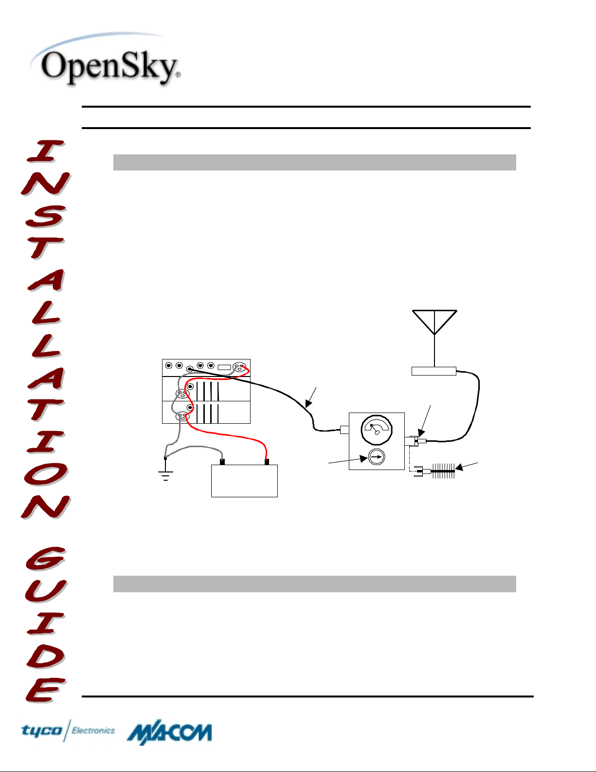
V-TAC
®
PWR
TNC to N-Serie s
Co ax ia l J u mper
OpenSky
DATE:
February 19, 2002
Page
♦ If the wattmet e r rea d in g is with in the
target range, record the value in the
appropriate spac e on the data collection
sheet at the end of this g uide.
♦ If the watt meter r eading is outside t he
target range, recheck the power source
and all connections and meas ure the RF
output power again. If this fails to produce
a reading within the target r ange, replace
the V-TAC and repeat this proced ure.
Antenna
N-S erie s to Mi ni -
UHF Adaptor
16 of 19
PWR
Dummy
Load
Ground
–+
Vehicle
Battery
Slug
(25 W, 400–
1000 MHz)
Wattmeter
Figure 2 – Wattmeter Connection
Testing with the Antenna
Actions Notes
1. Connect the watt met er to the VTAC and antenna for t esting
according to Figure 2.
2. Apply power t o the V-TAC and
switch to O CF mode, if necessary .
COPYRIGHT ©2002 Pri nte d in U.S. A.
♦ Remove the dummy load, if necessary,
and connect the antenna lead to t he
output side of the wattmeter (see
Figure 2).
♦ The V-TAC must be operating in OCF
mode in order to continue with the
M/A-COM
1011 Pawtucket Boulevard
Lowell, MA 01853
1-877-OPEN S KY
(1-877-673-6759)
Page 17

1-877-OPENSKY
WINST-0009 Rev – WIRELESS SYSTEM BUSINESS UNIT
SUBJECT:
Actions Notes
3. Position the slug to measure
4. Measure the forward RF power
5. Compare the wat t meter reading
6. Record the watt meter reading for
M-803 VTAC Installation Instructions
forw ar d RF power output.
output of the V-TAC.
with the target RF pow er output
range specified in the
column, opposite.
forw ar d power, or take remedial
action and measure the outp ut
again.
Notes
DATE:
testing procedure. If the Control Head
does not display “O CF” during startup
indicating that it is initializing in OCF
mode, use the procedure under
Changing Oper ating M odes
♦ Rotate the slug, if necessary. The arrow
on the face of the slug must point from
the V-TAC toward the antenna to
measure forw ard power.
♦ Key the microphone and note the
wattmeter reading. De-key the
microphone.
15–21 watts
TARGET VALUE RANG E
♦ If the wattmet e r rea d in g is with in the
target range, record the value in the
appropriate spac e on the data collection
sheet below.
♦ If the watt meter r eading is outside the
target range, verify that the operating
voltage of t he V-TAC is within the
specified range, r ec heck all connections,
and measure the forw ar d pow er again. If
this fails to produce a reading within the
target range, check all cabling a nd
connectio ns, and repeat t he testing
procedure to this point. In the event the
wattmeter reading still falls outside the
target range, replace the ante nna, make
sure all connectio ns are seated firmly,
and repeat the testing procedure.
February 19, 2002
17 of 19
Page
above.
7. Position the slug to measure
reverse, or r eflected, RF pow er.
8. Measure the reverse, or r eflected,
RF power.
COPYRIGHT ©2002 Pri nte d in U.S. A.
♦ Rotate the slug. The arrow on the face of
the slug must point from the antenna
toward the V-TAC to measure reverse, or
reflected, power.
♦ Key the microphone and note the
wattmeter reading. De-key the
microphone.
M/A-COM
1011 Pawtucket Boulevard
Lowell, MA 01853
1-877-OPEN S KY
(1-877-673-6759)
Page 18

1-877-OPENSKY
WINST-0009 Rev – WIRELESS SYSTEM BUSINESS UNIT
SUBJECT:
Actions Notes
9. Compare the wat t meter reading
10. Record t he wattmeter reading for
M-803 VTAC Installation Instructions
with the target RF pow er output
range specified in the
Notes
column, opposite.
reverse power, or take remedial
action and measure the outp ut
again.
DATE:
February 19, 2002
18 of 19
Page
2 watts or less
TARGET VALUE RANG E
♦ If the wattmet e r rea d in g is with in the
target range, record the value in the
appropriate spac e on the data collection
sheet at the end of this g uide.
♦ If the watt meter r eading is outside the
target range, make sure the antenna
inst a lle d is c onsis tent w ith the specifie d
frequency range of t he V-TAC. Recheck
all antenna connectio ns, a nd measure
the reverse power again. If this fails to
produce a reading withi n the target
range, replace the ante nna and repeat
the entire test ing procedure.
♦ Any value exceeding the maximum
allow a b le refle c ted power value will re sult
in a diminished RF output signal*.
11. Return the V-TAC to OTP mode
for normal communications.
♦ Use the procedure under
Operating M odes
above. The V-TAC is
Changing
now ready for normal communications.
*
The standard measure for comparing forward and reflected power is the Voltage Standing Wave Ratio (VSWR). Use the
values recorded for the installed unit’s forward and reflected power to compute the VSWR, if desired, using the following
formula:
the ideal value of 1, for instance, 1.2:1.
+= 1 , where
FR
PPVSWR
R
P
= reverse power and
F
P
= forward power. This value is expressed as a ratio to
COPYRIGHT ©2002 Pri nte d in U.S. A.
M/A-COM
1011 Pawtucket Boulevard
Lowell, MA 01853
1-877-OPEN S KY
(1-877-673-6759)
Page 19

1-877-OPENSKY
F
R
P
D
WINST-0009 Rev – WIRELESS SYSTEM BUSINESS UNIT
SUBJECT:
Copyright © 2002 M/A-COM. All rights reserved. No part of this publication may be reproduced, transmitted,
transcribed, stored in a retrieval system, or translated into any language, in any form or by any means,
electronic, mechanical, photocopying, recording, or otherwise, without prior written permission from
M/A-COM. The information furnished herein is believed to be accurate and reliable. However, no
responsibility is assumed by M/A-COM for its use, or for any infringements of patents or other rights of third
parties resulting from its use. All trademarks are the property of their respective owners.
M-803 VTAC Installation Instructions
DATE:
February 19, 2002
19 of 19
Page
Clip
"
Here
Enter the inform ati on r equested on this data col l ecti on sheet. Clip this form and file it as a permanent record of
the tested perfor m ance of the instal l ed V- TAC.
MRU
Serial Number
ate of Test
(mm/dd/yyyy)
VRB
Serial Number
Company Performing Installation Technician Performing Test
ower Into a Dummy
Load
RF Combiner
Serial Number
watts
Antenna Make and Model
watts
orward Power With
Antenna
eflected Power
With Antenna
watts
 Loading...