

Page 1

ECP-3406
M7300 Scan Model
Mobile Radio
User’s Guide
for Orleans County, NY
Training Session Notes
Trunked Radio System
Page 2

ECP-3406 page 3
Project 25
Interoperable digital radio system standard
Intended for all public safety LMR bands
(VHF, UHF, and 800 MHz)
Developed Jointly by:
TIA
Association of Public-Safety Communications Officials (APCO)
National Association of State Telecommunications Directors
(NASTD)
Various agencies of the Federal government (FED) in the early
90’s to improve spectral efficiencies
TIA/EIA Standard in 1999. Under TIA/EIA-102
Page 3

ECP-3406 page 4
Project 25 Benefits
Key benefits sought by the user community:
– Competitive procurement of equipment
– Interoperability of equipment
– Spectrum efficiency
– User-friendly operation equivalent to today's public
safety equipment and common across all bands,
system configurations, services, and
manufacturers
Page 4

ECP-3406 page 5
* SAFETY ITEMS *
DO NOT...operate the mobile radio when someone is outside the vehicle
within two feet of the antenna. This is a recommendation from OSHA
that applies to any type of radio transmitter such as a cellular
telephone, CB radio, our old radio system, or our new radios.
DO NOT...operate the mobile radio if any of the antenna connectors are
loose. This is a basic safety precaution. If the antenna cable or
connectors are loose, please place a service call for repair.
DO NOT...operate the mobile radio near or in an area where blasting is
taking place. Anyone using radio controlled explosives must post
signs. If you see a caution sign about blasting in the area, you must
turn your radio off. This applies to any radio equipment capable of
transmitting: phones, CBs, etc.
DO NOT...operate the mobile radio in an explosive atmosphere. The
radio is an electrical device with switches that can cause an explosion
in an explosive atmosphere. If you can operate your vehicle or any
power tools, it is safe to use the radio.
Page 5

ECP-3406 page 6
Operating Rules and Regulations
The Federal Communications Commission sets all rules for two-
way radio use. All users of two-way radio equipment should be
familiar with these basic rule requirements.
It is a violation of FCC rules to interrupt any distress or
emergency message
Any use of profane or obscene language is prohibited
It is against the law to send false call letters or a false distress
or emergency message
All messages must be brief and limited to the business need
It is a violation of FCC rules to send personal messages,
unless in an emergency
The FCC requires that radio systems be identified by use of
the assigned Call Letters – the radio system does this
automatically
Page 6

ECP-3406 page 7
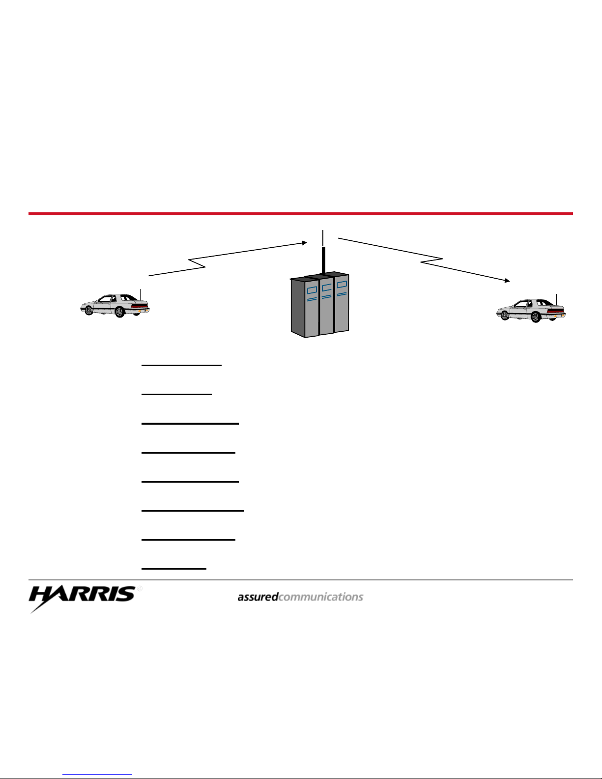
Conventional vs. Trunked
Computerized Assignment of Channels
Service Employee
Customer
Conventional
Trunked
Service Counter
Service Counter
Page 7
ECP-3406 page 8
Why Trunking?
Improves spectral efficiency
Relieves the user from managing the channel
Encourages cross agency / shared communications
Establishes communications privacy
Encourages private communications
Discourages eavesdropping by scanners
Establishes “queuing” rather than “waiting”
Enables priority use during busy times
Trunking:
Page 8

ECP-3406 page 9
Trunked Radio System Features
Digital Control Channel
Multiple Working Channels
< 0.5 Second Access
Group & Individual Voice Calls
Logical ID (LID) for each radio
Late / Delayed Entry
Emergency Calls
Queuing with Priority
Unit Enable / Disable
Wide Area Coverage
Page 9

ECP-3406 page 10
???
Communication Range
Many factors affect range:
Site Location
Urban Clutter
Reflections / Multipath
Ducting over Water
Heavy vegetation
Weather
Frequency
Page 10

ECP-3406 page 11
Multisite - What the Radios Do
Units inform the System of their location:
Each time the Radio is powered up
Each time a System selection is made
Each time a Group selection is made
When Radio detects a high bit error rate on the Control Channel,
Radio will look for another site (algorithm programmed in radio),
Automatically switches to new site when criteria met
Site 1
Site 2
Page 11
ECP-3406 page 13
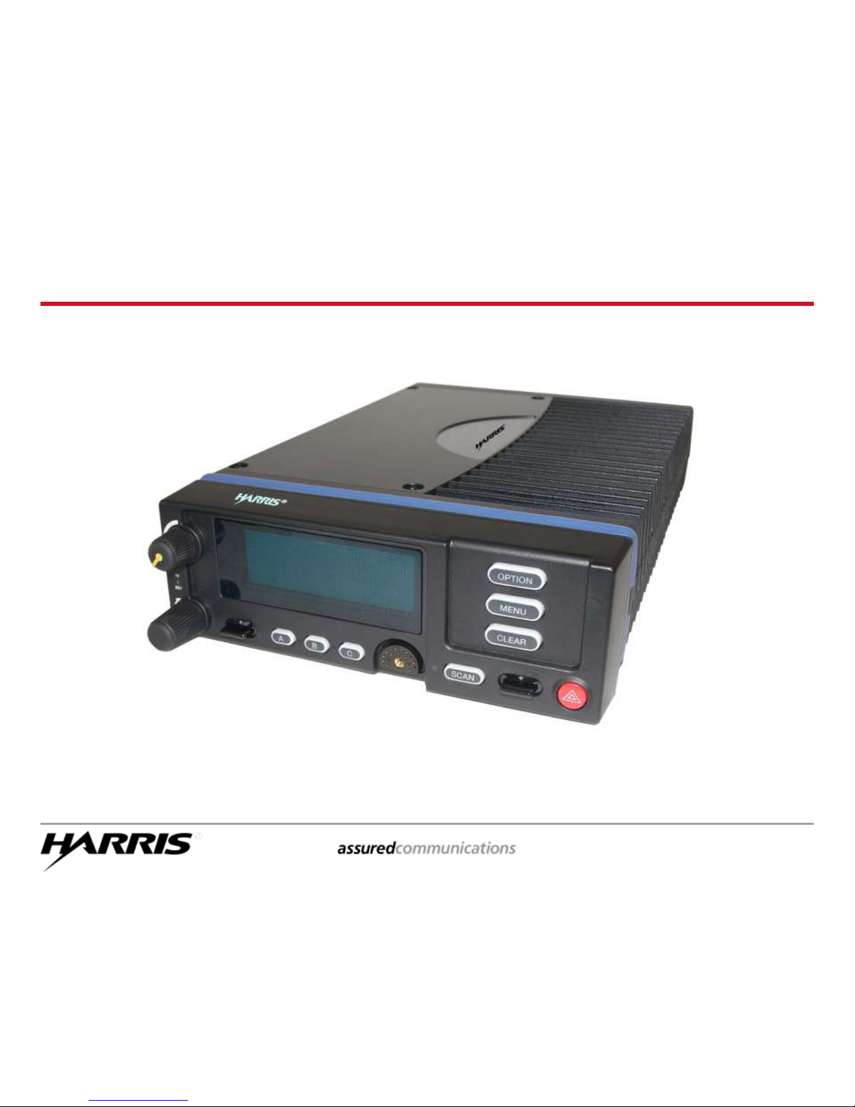
M7300 Scan Model Operation
Page 12
ECP-3406 page 14
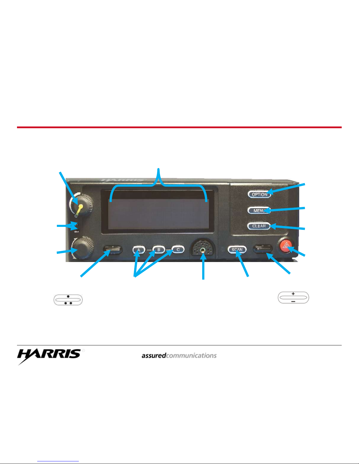
Control Head Functions
OPTION
Key
MENU
Key
On/Off
& Volume
Control
Knob
Group
Select
Knob
Microphone
Connection
CLEAR
Key
Ramp
Control
Scan
Key
Scroll
Control
Emergency
Button
Programmable
Soft Keys
Display
Area
TX & BSY
Indicators
Page 13
ECP-3406 page 15
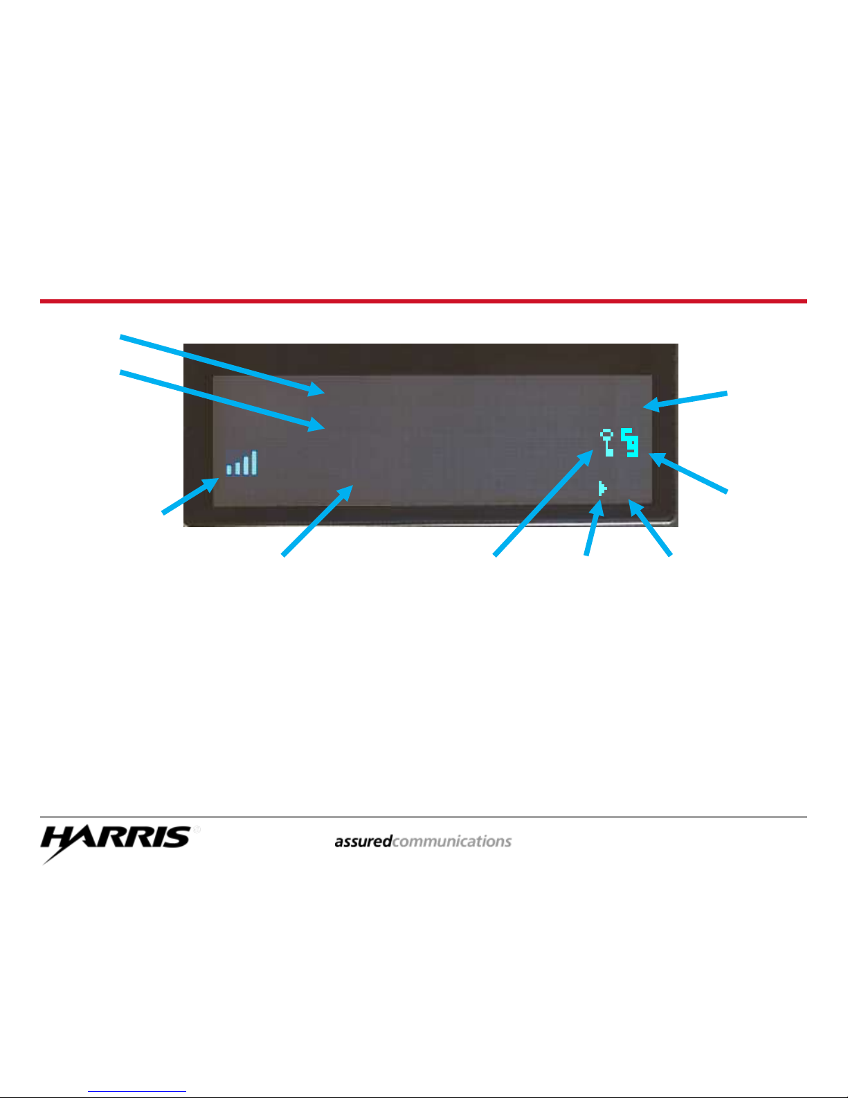
Display Information
Volume Bars
indicates relative
volume level
Line 1
Line 2
Mode
Icon *
Channel
Guard
Icon
Encryption
Icon
P25
A or D
Scan On
Icon
rotates
Scan
Priority
Icon
III, II, or I
If you are attached to a P-25 system, the P25 icon will appear
If you are attached to an analog system, an A icon will appear
If you are attached to a digital system, a D icon will appear
Mode Icon Information
*
see next page
for display
messages
VOL
P
25
III
SYSTEM
TALK GROUP
VOL = 1-40
Volume Level
only visible as
volume level is
being adjusted
Page 14

ECP-3406 page 16
Current Talk Group Name (example: TALK GROUP)
System Busy (SYS BUSY)
Call Denied (DENIED)
Individual Call (*INDV*)
Control Channel Scan (CC SCAN)
Wide Area Scan (WA SCAN)
Receive Emergency (*RX EMER*)
Transmit Emergency (*TX EMER*)
Current System Name (example: SYSTEM)
Volume Level (VOL = 10)
Caller Identification (GR 1234)
Call Queued (QUEUED)
‘Who Has Called’ (* WHC *)
Displayed Messages
• LINE 1:
• LINE 2:
• LINE 3:
Volume Level (VOL = 30)
Range: OFF (minimum) – 40 (maximum)
Line 3 only visible while adjustment is being made
Page 15
ECP-3406 page 17
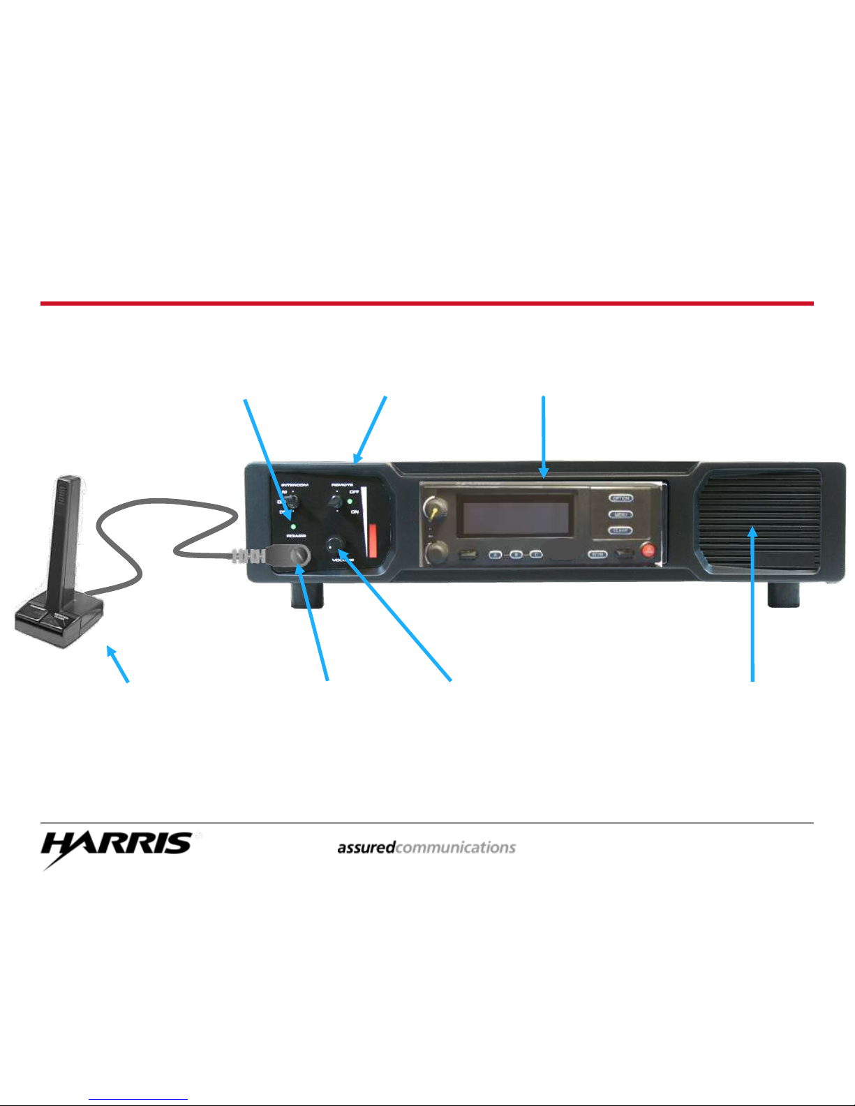
Desk Top
Microphone
M7300 Desk Top Station
Speaker
Remote Control
Panel
Microphone
Jack
M7300 Scan
Model Radio
Volume
Control
Station Power
Switch
(on back)
Power
Indicator
Page 16

ECP-3406 page 18
Alert Tones
Call Originate short mid-pitched beep (“beep”)
Autokey short mid-pitched beep sounding after queued
and an open channel is gained (“beep”)
Call Queued high-pitched tone (“beep”) sounded when the
system places the call request in a queue
System Busy three low-pitched tones (“dut-dut-dut”), only with
I-Calls
Call Denied low-pitched tone (“bomp”) sounded when the
radio is not authorized on the selected system
Timing Out five short high-pitched warning tones (“beep..”)
followed by a low-pitched tone (“bomp”)
Key Press Alert short tone “beep”= access; low-pitched
“bomp”= denial
Missed I-Call telephone ring sounded when an incoming
individual call is not answered
Page 17

ECP-3406 page 20
Basic Radio Operation
Page 18

ECP-3406 page 21
Changing Talk Groups
Turn the GROUP SELECT knob to select a group or a channel
Group/channel names appear on Line 2 of the display
SYSTEM 1
TRNG 2
VOL
P
25
GROUP
SELECT
KNOB
GROUP NAMES
DISPLAYED
Page 19

ECP-3406 page 22
Adjusting the Volume
SYSTEM 1
TRNG 2
VOL= 30
VOL
P
25
Turn the VOLUME CONTROL knob to set the desired volume
level of received traffic (minimum = OFF / loudest = 40)
The numeric volume level is only displayed as the knob is being
turned, and will disappear when knob movement is stopped
The 1-5 bars Relative Volume Icon remains visible
VOLUME
CONTROL
KNOB
RELATIVE
VOLUME ICON
DISPLAYED
NUMERIC VOLUME
LEVEL DISPLAYED
DURING ADJUSTMENT
Page 20

ECP-3406 page 23
Making A Group Call
SYSTEM 1
TRNG 1
VOL
P
25
Rotate the GROUP SELECT knob to select the group you want to
reach
The Group names appear on Line 2 of the display
PTT to transmit to the talk group
PTT
GROUP
SELECT
KNOB
GROUP NAMES
DISPLAYED
Page 21

ECP-3406 page 24
Receiving A Group Call
Line 1 displays the caller’s Radio ID
Line 2 displays the talk group
If in Scan and you want to talk to the caller, change to the
talk group that appeared in the display
PTT
(Rotating
Scan icon
displayed)
GR 1234
TRNG 1
VOL
25
P
PTT
CALLER’S
RADIO ID
OR ALIAS
CALLER’S
TALK GROUP
II
Page 22

ECP-3406 page 25
Changing Systems
SYSTEM 2
TRNG 1
VOL
D
Toggle the RAMP CONTROL button to select a system
System names appear on Line 1 of the display
The type of the new System may change appearance of icon
SYSTEM NAMES
DISPLAYED
RAMP
CONTROL
SYSTEM TYPE MAY CHANGE
P-25 – D (digital) – A (analog)
Page 23

ECP-3406 page 26
Changing the Display Brightness
Press the MENU key
Use the RAMP CONTROL to find BCK LIGHT
Press the MENU key again
BCKL ADJ will appear in the display
Use the RAMP CONTROL button to change the brightness of
the display intensity
Press the MENU key again to save the new setting
BCKL ADJ
TRNG 1
VOL
P
25
RAMP
CONTROL
MENU
KEY
BRIGHTNESS
LEVEL
DISPLAYED
Page 24

ECP-3406 page 27
Changing the Display Contrast
Press the MENU key
Use the RAMP CONTROL to find CONTRAST
Press the MENU key again
CNTRST = 1, 2, 3, 4, 5, 6, 7, 8 will appear in the display,
along with the current setting
Use the RAMP CONTROL button to change the contrast level
Press the MENU key again to save the new setting
CNTRST = 8
TRNG 1
VOL
P
25
CONTRAST
LEVEL
DISPLAYED
RAMP
CONTROL
MENU
KEY
Page 25

ECP-3406 page 28
Emergencies
Page 26

ECP-3406 page 29
Declaring an Emergency*
Note: This feature only available when in the trunked
mode – not available in conventional modes
Press and hold the EMERGENCY key for a pre-programmed
amount of time
Wait until * TXEMER * appears in display
* TXEMER * will flash, alternating with the current group
PTT and talk
SYSTEM 1
* TXEMER *
VOL
25
P
EMERGENCY
BUTTON
*TXEMER*
APPEARS
PTT
Page 27

ECP-3406 page 30
Receiving an Emergency
GR 1234
* RXEMER *
VOL
25
P
The Radio ID or Alias of the radio that declared the emergency will
appear on Line 1 while that person is transmitting
* RXEMER * will appear in display, flashing alternatively with the
current talk group until the emergency is cleared
PTT and respond if appropriate
PTT
CALLER’S ID OR ALIAS
DISPLAYED
*RXEMER*
APPEARS
Page 28

ECP-3406 page 31
Clearing an Emergency*
Press and hold the CLEAR key
Press and hold the EMERGENCY key
The display will return to the condition previous to the
emergency state
*
Supervisory radios only
SYSTEM 1
TRNG 1
VOL
P
25
DISPLAY
RETURNS
TO NORMAL
CLEAR
KEY
EMERGENCY
BUTTON
Page 29

ECP-3406 page 32
Call Scanning
Group 1
Group 2
?
Page 30

ECP-3406 page 33
Group Call Scanning
The radio is able to monitor multiple groups, but the radio can only receive
one group at a time
The radio can scan only those groups on a “Scan List”
This list can be programmed by the user, or
The list may be directly programmed into the radio by the Network
Administrator
Turning the Scan function On or Off can be:
Fixed in programming by the Network Administrator, or
Controlled by the radio user
Radio can have up to two “Priority Talk Groups” designated
Priority 1 Talk Group
Priority 2 Talk Group
Priority Talk Groups can be assigned by the radio user, or they might be
fixed in the programming by the Network Administrator
The radio will be extracted from listening to a scanned call if a call with a
higher priority is received
Page 31

ECP-3406 page 34
Turning SCAN On/Off
Note: The microphone may need to be on hook for scanning to function
Press SCAN to turn on the scan function – any group in the scan
list will be scanned
The rotating icon displayed ( ) indicates SCAN is on
Press SCAN again to turn off the scan function (no icon)
SYSTEM 1
TRNG 1
VOL
P
25
SCAN ICON
APPEARS
SCAN
BUTTON
Page 32

ECP-3406 page 35
Establishing A Scan List
SYSTEM 1
TRNG 1
VOL
P
25
To Scan, you must have a Scan List
To create a Scan List (or edit an existing Scan List) you must have
the Scan function turned off
Press the SCAN button to turn scan off (the scan icon disappears)
SCAN ICON
DISAPPEARS
SCAN
BUTTON
Page 33

ECP-3406 page 36
Adding a Talk Group to the Scan List
TRNG 3
S
VOL
P
25
Select the group you wish to scan
Make sure Scan is turned OFF (no rotating scan icon )
Press scan ramp up (+) to add the group to the scan list
An S will appear briefly to indicate the group is in the scan list
The scan priority icon (III) will also be displayed
III
S APPEARS BRIEFLY
GROUP
SELECT
KNOB
III SCAN PRIORITY
ICON DISPLAYED
SCAN
BUTTON
SCAN
RAMP
CONTROL
Page 34

ECP-3406 page 37
Creating a Priority 2 Talk Group
TRNG 3
2
VOL
P
25
Select the group you wish to make your priority 2 talk group
Press scan ramp up (+) once to make the group the Priority 2
scanned talk group
A “2” will appear briefly
The Scan priority icon will also change to a II
II
2 APPEARS BRIEFLY
GROUP
SELECT
KNOB
II SCAN PRIORITY
ICON DISPLAYED
SCAN
BUTTON
SCAN
RAMP
CONTROL
Page 35

ECP-3406 page 38
Creating a Priority 1 Talk Group
TRNG 3
1
VOL
P
25
Select the group you wish to make your priority 1 talk group
Press scan ramp up (+) once to make the group the Priority 1
scanned talk group
A “1” will appear briefly
The Scan priority icon will also change to a I
I
1 APPEARS BRIEFLY
GROUP
SELECT
KNOB
ISCAN PRIORITY
ICON DISPLAYED
SCAN
BUTTON
SCAN
RAMP
CONTROL
Page 36

ECP-3406 page 39
Deleting Groups from the Scan List
SYSTEM 1
TRNG 1
VOL
P
25
Select the group you wish to delete from the Scan List
Make sure Scan is turned OFF (no rotating Scan icon )
Press the scan ramp down ( – ) to delete the group from the
Scan List
Notice the III, II, or I icons disappear from the display
GROUP
SELECT
KNOB
NO SCAN
ICON
SCAN PRIORITY
ICON DISAPPEARS
SCAN
BUTTON
SCAN RAMP
CONTROL
Page 37

ECP-3406 page 40
Special Calls
Individual Calls & Telephone Calls
Page 38

ECP-3406 page 41
Sending a Individual Call
Note: While in the individual call mode, you will miss all talk group calls
Push the MENU key
Use the RAMP CONTROL to locate INDIVIDUAL
Push MENU key again to access the pre-programmed list of radio units
or aliases
Use the RAMP CONTROL to find the desired unit
PTT – only that radio will hear you
Press the CLEAR key to return to group call mode
CAPTAIN
INDV= 12
VOL
25
P
PTT
CLEAR
KEY
MENU
KEY
RAMP
CONTROL
Page 39

ECP-3406 page 42
Receiving an Individual Call
Note: While in the individual call mode, you will miss all talk group calls
Line 1 displays the Radio ID of the caller
Line 2 displays * INDV *
PTT to answer the caller
Press the CLEAR key to return to group call mode
ID= 12345
* INDV *
VOL
25
P
PTT
CALLER’S RADIO ID
OR ALIAS DISPLAYED
*INDV*
DISPLAYED
CLEAR
KEY
Page 40

ECP-3406 page 43
Missing an Individual Call
Line 1 will display * WHC * and the radio will begin ringing
To stop the ringing, press the CLEAR button
If an Individual Call is not answered:
* WHC *
TRNG 1
VOL
P
25
* WHC * DISPLAYED
CLEAR
KEY
Page 41

ECP-3406 page 44
Returning a Missed Individual Call
Note: The last ten individual calls received are stored in the WHC Index list
Push the MENU key
Use the RAMP CONTROL to locate INDIVIDUAL
Push MENU key again
Line 2 shows the WHCI (Who Has Called Index) entry number
Line 1 shows the LID or alias of the unit that sent the message
PTT to return the call
1234
WHCI= 1
VOL
25
P
PTT
CALLER’S RADIO ID
OR ALIAS DISPLAYED
WHCI ENTRY
NUMBER
DISPLAYED
MENU
KEY
Page 42

ECP-3406 page 46
Telephone Interconnect Calls
In order to connect to a telephone scan, your system must
be equipped with a Public Service Telephone Network
(PSTN) interface device of some type
You will receive specific instructions regarding disclosure
of the direct-dial-in capabilities of your telephone interface
system as they apply to your radio system utilization and
to your organization
Page 43

ECP-3406 page 47
Sending a Phone Call
Note: The radio is capable of one-way conversation only –
The caller
cannot
be heard if the radio PTT is pressed
Push the MENU key
Use the RAMP CONTROL to find PHN CALL
Push MENU key again
Use the RAMP CONTROL to find the desired number
PTT
Press the CLEAR key to return to group call mode
5551234
* PHONE *
VOL
25
P
PTT
RAMP
CONTROL
CLEAR
KEY
MENU
KEY
Page 44

ECP-3406 page 48
Receiving a Phone Call
PTT to answer the call
Note: The radio is capable of one-way conversation only – The
caller can only hear the radio when the PTT is pressed and the
caller can only be heard when the PTT is released
PHONE
* INDV *
VOL
25
P
PTT
Page 45

ECP-3406 page 49
Special Licensed Features
Status & Message Alert Calls
Request-to-Talk Function
Public Address Feature
Intercom Feature
External Speaker Option
Note – Your radio may be using any of these features (or none of
them), and the feature used may be enabled differently – Always
check with your management to determine if these features are
to be used and how they will be used.
Page 46

ECP-3406 page 50
Status & Message Operations
STATUS operation allows a pre-programmed status condition to
be transmitted to a P25 trunked tower site
MESSAGE operation allows a pre-programmed text message to
be transmitted to a P25 trunked tower site
Each STATUS and MESSAGE is assigned an ID that is cross-
referenced to a determined condition (ie., Off Duty, In Service,
Transporting, or some similar message)
The messages are routed from the tower site to a specific
dispatch console (or to several specific consoles) that have been
pre-designated to receive that particular message (based on the
assigned ID number)
Each STATUS condition message and each MESSAGE text is pre-
programmed by the system administrator – individual radio
operators cannot enter their own messages as “text” entries
nor can they choose which console(s) receive the message
Page 47

ECP-3406 page 51
Status Message Operation
Press the MENU key
Use the RAMP CONTROL to find STATUS
Press the MENU key again
Use the RAMP CONTROL to locate the status message to be sent
(up to 10 different status messages can be pre-programmed)
Press the MENU key again to send the status message
STATUS = 8
TRNG 1
VOL
P
25
STATUS
MESSAGE
NUMBER
DISPLAYED
RAMP
CONTROL
MENU
KEY
Page 48

ECP-3406 page 52
RTT Message Operation
Press the MENU key
Use the RAMP CONTROL to find MESSAGE
Press the MENU key again
Use the RAMP CONTROL to locate the RTT message to be sent (up
to 10 different messages can be pre-programmed)
Press the MENU key again to send the RTT message
MESSAGE = 3
TRNG 1
VOL
P
25
MESSAGE
NUMBER
DISPLAYED
RAMP
CONTROL
MENU
KEY
Page 49

ECP-3406 page 53
PTT
“Request-to-Talk” Function
Press and release the OPTION key to send a “Request-to-Talk”
notification to the dispatcher
When the dispatcher acknowledges your request, press the PTT
and transmit normally
OPTION
KEY
SYSTEM 1
TRNG 1
VOL
P
25
Note – Each customer may have a different method to signal RTT (RTT-Normal,
RTT-Priority, or RTT-Cancel), which may result in certain keypad keys or
control head buttons being mapped to perform specific functions.
Always verify RTT operation & methods with your management.
Page 50

ECP-3406 page 54
PTT
Public Address Feature
MENU
KEY
VOL
P
25
MENU
PUBADDR
Press the MENU key to access the radio menu options
Use the RAMP CONTROL to locate “PubAddr”
Push MENU key again to enable the Public Address feature
PTT will route voice traffic to the PA speaker and will not transmit to the talk
group
Press the CLEAR key to exit the PA feature and return to normal talk group
mode
NOTE – Additional Equipment Required
RAMP CONTROL
CLEAR
KEY
Page 51

ECP-3406 page 55
PTT
Intercom Operation
MENU
KEY
VOL
P
25
NOTE – Additional Equipment Required
RAMP CONTROL
CLEAR
KEY
Press the MENU key to access the radio menu options
Use the RAMP CONTROL to locate “Intercom”
Push MENU key again to enable the Intercom feature
When enabled, PTT from any microphone will route voice traffic to other
control head speakers and will not transmit to the talk group
Press the CLEAR key to exit the Intercom feature and return to normal talk
group mode
MENU
INTERCOM
Page 52

ECP-3406 page 56
External Speaker Feature
MENU
EXTSPKR
VOL
P
25
RAMP
CONTROL
MENU
KEY
NOTE – Additional Equipment Required
CLEAR
KEY
Press the MENU key to access the radio menu options
Use the RAMP CONTROL to locate “ExtSpkr”
Push MENU key again to enable the External Speaker feature
All received voice traffic will be re-routed to the vehicle’s external speaker
and will not be carried by the vehicle’s internal speaker
Press the CLEAR key to disable the external speaker and return to normal
radio operation
Page 53

ECP-3406 page 57
Radio Care
Troubleshooting Tips
Page 54

ECP-3406 page 58
Troubleshooting Tips
Issue What do you do?
Any talk group or system configuration
or structuring (fleet mapping) issue, or
any RF coverage issues
Contact your management
to report the issue
Any physical radio equipment issues
Contact your management
to report the issue
Any failure of the radio or any error
code appears in the display that is not
explained
Contact your management
to report the issue
Slight delay in audio
All digital communications
have a slight delay in audio
Only noticeable when radios
are in very close proximity
Page 55

RF Communication Division | 221 Jefferson Ridge Parkway | Lynchburg, VA USA 24501
Tel: 800-528-7711 www.harris.com
Copyright© 2012 Harris Corporation
Harris is a registered trademark of Harris Corporation.
 Loading...