

HARRIS M7200 Users Manual

Rhein Tech Laboratories Client: M/A COM, Inc.
360 Herndon Parkway Model: CS-7200 OpenSky Control Station
Suite 1400
Herndon, VA 20170 Standards: Part 90/RSS-119
http://www.rheintech.com
Report #: 2007152
FCC ID: BV8M7200/3670A-M7200
Appendix F: User Manual
Please refer to the following pages.
21 of 30

Operator’s Manual
MM-011709-001
Feb/07
CS-7200 with SP-103
Control Station with Deskset

MM-011709-001
MANUAL REVISION HISTORY
REV DATE REASON FOR REVISION
Rev. - Feb/07 Initial Release.
M/A-COM Technical Publications would particularly appreciate feedback on any errors found in this document and
suggestions on how the document could be improved. Submit your comments and sug gestions t o:
Wireless Systems Business Unit or fax your comments to: (434) 455-6851
M/A-COM, Inc.
Technical Publications or e-mail us at: techpubs@tycoelectronics.com
221 Jefferson Ridge Parkway
Lynchburg, VA 24501
CREDITS
This device is made under license under one or more of the following US patents: 4,590,473; 4,636,791; 5,148,482;
5,185,796; 5,271,017; 5,377,229; 4,716,407; 4,972,460; 5,502,767; 5,146 ,497; 5,164,986; 5,185,795.
The voice coding technology embodied in this product is protected by intellectual property rights including patent rights,
copyrights, and trade secrets of Digital Voice Systems, Inc. The user of this technology is explicitly prohibited from
attempting to decompile, reverse engineer, or disassemble the Object Code, or in any other way con vert the Object Code into
human-readable form.
OpenSky is a registered trademark of M/A-COM, Inc.
All other brand and product names are trademarks, registered trademarks or service marks of their respective holders.
This product conforms to the European Union WEEE Directive 2002/96/EC. Do not dispose of this product in a
public landfill. Take it to a recycling center at the end of its life.
NOTICE!
This manual covers M/A-COM products manufactured and sold by M/A-COM, Inc.
Repairs to this equipment should be made only by an authorized service technician or facility designa te d by the su ppli er. An y
repairs, alterations or substitutions of recommended parts made by the user to this equipment not approved by the
manufacturer could void the user's authority to operate the equipment in addition to the manufacturer's warranty.
This manual is published by M/A-COM, Inc., without any warranty. I mprovements and changes to this manual necessitated
by typographical errors, inaccuracies of current information, or improve ments to programs and/or equipment, may be made
by M/A-COM, Inc., at any time and withou t notice. Such changes will b e incorporated into new editions of this manual. No
part of this manual may be reproduced or transmitted in any form or by any means, electronic or mechanical, including
photocopying and recording, for any purpose, without the express written permission of M/A-COM, Inc.
Copyright© 2007 M/A-COM, Inc. All rights reserved.
2

MM-011709-001
TABLE OF CONTENTS
Page
1 SAFETY INFORMATION ......................................................................................................................... 6
1.1 IMPORTANT SAFETY INSTRUCTIONS ............................................................................................6
1.2 FCC REGULATIONS.............................................................................................................................7
1.2.1 Antennas....................................................................................................................................7
2 PRODUCT DESCRIPTION ....................................................................................................................... 8
2.1 CS-7200 CONTROL STATION .............................................................................................................8
2.2 MODES OF OPERATION......................................................................................................................8
2.2.1 VOICE OPERATION............................................................................................................... 8
2.2.2 DATA OPERATION................................................................................................................9
2.2.3 INTERCOM OPERATION ......................................................................................................9
2.3 SP-103 DESKSET................................................................................................................................... 9
2.4 TRCM-103 TONE REMOTE CONTROL MODULE.......................................................................... 10
2.5 PERSONALITY.................................................................................................................................... 10
2.5.1 Profiles .................................................................................................................................... 10
2.5.2 Talk Groups.............................................................................................................................11
3 CS-7200/SP-103 OPERATION ................................................................................................................. 12
3.1 CONTROLS AND INDICATORS .......................................................................................................12
3.1.1 CS-7200 Front Panel............................................................................................................... 12
3.1.2 CS-7200 Rear Panel................................................................................................................ 12
3.1.3 SP-103 Front Panel.................................................................................................................. 13
3.1.4 SP-103 Rear Panel...................................................................................................................13
3.2 DISPLAY OVERVIEW ........................................................................................................................15
3.2.1 Network Connectivity Icon.....................................................................................................15
3.2.2 Volume Level Icon.................................................................................................................. 15
3.2.3 Display’s Top Line.................................................................................................................. 15
3.2.4 Display’s Bottom Line ............................................................................................................15
3.2.5 Dwell Display..........................................................................................................................18
3.2.6 Menu Display and Control Area..............................................................................................18
3.2.7 Dwell Display User-Selectable................................................................................................19
3.3 BASIC RADIO OPERATION .............................................................................................................. 19
3.3.1 POWER UP............................................................................................................................. 19
3.3.2 Self-Test..................................................................................................................................20
3.3.3 Logging In to the Network...................................................................................................... 20
3.3.4 Logging off the Network.........................................................................................................20
3.3.5 POWER DOWN......................................................................................................................20
3.3.6 Receiving and Transmitting Voice Calls................................................................................. 20
3.3.7 Tones....................................................................................................................................... 21
3.3.8 Adjusting Side Tone Audio Level........................................................................................... 22
3.3.9 Adjusting Display & Button Backlight Brightness ................................................................. 23
3.3.10 Adjusting Speaker/Headset Audio Treble Level..................................................................... 23
3.3.11 Checking or Changing the Active Profile ...............................................................................23
3.3.12 Checking or Changing the Selected Talk Group..................................................................... 24
3.4 INTERCOM MODE.............................................................................................................................. 25
3.5 TALK GROUP LOCK OUT ................................................................................................................. 25
3.5.1 Locking Out a Talk Group...................................................................................................... 26
3.5.2 Unlocking a Talk Group..........................................................................................................26
3.6 SCAN MODE........................................................................................................................................27
3.6.1 Checking or Changing Active Scan Mode ..............................................................................28
3

MM-011709-001
TABLE OF CONTENTS
3.6.2 Scanning Priority.....................................................................................................................28
3.7 SELECTIVE CALL...............................................................................................................................29
3.7.1 Making a Selective Call ..........................................................................................................29
3.7.2 Receiving a Selective Call.......................................................................................................30
3.8 SELECTIVE ALERT ............................................................................................................................30
3.8.1 Sending Selective Alert Messages...........................................................................................30
3.8.2 Receiving Selective Alert Messages .......................................................................................31
3.8.3 Defining Pre-Programmed Messages......................................................................................32
3.9 TELEPHONE INTERCONNECT CALLS ........................................................................................... 32
3.10 EMERGENCY COMMUNICATIONS.................................................................................. 32
3.10.1 Declaring an Emergency Call or Alert.................................................................................... 33
3.10.2 Clearing an Emergency Call or Alert...................................................................................... 33
3.10.3 Silent Emergency ....................................................................................................................34
3.10.4 Receiving an Emergency Call................................................................................................. 34
3.10.5 Dismissing an Emergency Call ...............................................................................................34
3.11 DUAL-TONE MULTI-FREQUENCY KEYPAD.................................................................. 35
3.11.1 Password Entry........................................................................................................................35
3.11.2 Overdial................................................................................................................................... 35
3.12 ENCRYPTION........................................................................................................................35
3.12.1 Automatic Encryption .............................................................................................................36
3.12.2 Manual Encryption.................................................................................................................. 36
3.13 PRESET BUTTONS............................................................................................................... 37
3.14 DYNAMIC REGROUPING................................................................................................... 37
3.15 ENGINEERING DISPLAY....................................................................................................38
3.15.1 Voice and Data Registration Codes......................................................................................... 38
3.15.2 Transceiver Status ...................................................................................................................38
3.15.3 Receive Signal Strength Indication (RSSI)............................................................................. 39
3.15.4 Control Block Symbol Error Rate (CBSER)...........................................................................39
4 CS-7200/TRCM-103 OPERATION.......................................................................................................... 40
4.1 POWER UP ...........................................................................................................................................40
4.2 NETWORK LOG ON ...........................................................................................................................40
4.3 SELF-TEST ...........................................................................................................................................40
4.4 CONTROLS AND INDICATORS .......................................................................................................40
4.5 VOICE CALLS .....................................................................................................................................40
4.5.1 Receiving a Voice Call............................................................................................................ 40
4.5.2 How to Make a Voice Call...................................................................................................... 40
4.6 RADIO TONES..................................................................................................................................... 41
4.7 POWER DOWN....................................................................................................................................41
5 BASIC TROUBLESHOOTING ............................................................................................................... 42
6 WARRANTY.............................................................................................................................................. 43
Page
4

MM-011709-001
TABLE OF CONTENTS
Page
FIGURES
Figure 2-1: CS-7200 .........................................................................................................................................8
Figure 2-2: SP-103 Deskset.............................................................................................................................. 9
Figure 2-3: Personality Structure Example.....................................................................................................10
Figure 3-1: CS-7200 Front Panel....................................................................................................................12
Figure 3-2: CS-7200 Rear Panel..................................................................................................................... 12
Figure 3-3: SP-103 Front Panel...................................................................................................................... 13
Figure 3-4: SP-103 Rear Panel .......................................................................................................................13
Figure 3-5: Sample Display (Talk Group Menu Session)...............................................................................15
Figure 3-6: Top and Bottom Display Lines....................................................................................................18
Figure 3-7: Dwell Display and Speaker Volume Icon.................................................................................... 19
Figure 3-8: Side Tones Menu .........................................................................................................................23
Figure 3-9: Profile Menu ................................................................................................................................24
Figure 3-10: Talk Group Menu....................................................................................................................... 25
Figure 3-11: Lock Out Menu..........................................................................................................................27
Figure 3-12: Example Engineering Display ................................................................................................... 38
TABLES
Table 3-1: SP-103 Front Panel Controls and Functions .................................................................................14
Table 3-2: SP-103 Rear Panel Connections and Functions ............................................................................14
Table 3-3: Basic Menu Structure.................................................................................................................... 16
Table 3-4: Display Parts and Functions..........................................................................................................18
Table 3-5: Alert Tones.................................................................................................................................... 21
Table 3-6: Scan Modes ................................................................................................................................... 28
Table 3-7: Possible Status of Selective Alert.................................................................................................. 31
Table 3-8: Voice Registration Codes.............................................................................................................. 38
Table 3-9: Data Registration Codes................................................................................................................ 39
Table 5-1: Basic Troubleshooting................................................................................................................... 42
5

MM-011709-001
1 SAFETY INFORMATION
1.1 IMPORTANT SAFETY INSTRUCTIONS
The user is responsible at all times for the proper operation and maintenance of the
equipment.
1. Read these instructions.
2. Keep these instructions.
3. Heed all warnings.
4. Follow all instructions.
5. Do not use this apparatus near water.
6. Clean only with dry cloth.
7. Do not block any ventilation openings. Install in accordance with the manufacturer’s instructions.
8. Do not install near any heat sources such as radiators, heat registers, stoves, or other apparatus
(including amplifiers) that produce heat.
9. Do not defeat the safety purpose of the polarized or grounding-type plug. A polarized plug has two
blades with one wider than the other. A grounding type plug has two blades and a third grounding
prong. The wide blade or the third prong is provided for your safety. If the provided plug does not fit
into your outlet, consult an electrician for replacement of the obsolete outlet.
10. Protect the power cord from being walked on or pinched particularly at plugs, convenience
receptacles, and the point where they exit from the apparatus.
11. Only use attachments/accessories specified by the manufacturer.
12. Use only with the cart, stand, tripod, bracket, or tabl e specified by the manufacturer, or sold with the
apparatus. When a cart is used, use caution when moving the cart/apparatus combination to avoid
injury from tip-over.
13. Unplug this apparatus during lightning storms or when unused for long periods of time.
14. Refer all servicing to qualified service personnel. Servicing is required when the apparatus has been
damaged in any way, such as power-supply cord or plug is damaged, liquid has been spilled or
objects have fallen into the apparatus, the apparatus has been exposed to rain or moisture, does not
operate normally, or has been dropped.
6
15. Warning: The lightning bolt signifies an alert to the user of the presence of un-insulated “dangerous
voltage” within the product’s enclosure that may be of significant magnitude to constitute a risk of
electric shock to persons.

16. Warning: The exclamation point alerts the user to the presence of important operation and
maintenance (service) instructions in the literature accompanying the product.
17. Outdoor Use Warning: To reduce the risk of Fire or Electric Shock, Do Not Expose This Apparatus to
Rain or Moisture.
18. Wet Location Warning: Apparatus shall not be exposed to dripping or splashing and no objects filled
with liquids, such as vases, shall be placed on the apparatus.
1.2 FCC REGULATIONS
Use, installation and service of this equipment as summarized within this Manual will ensure the safe
performance of this equipment and will result in user exposure substantially below FCC recommended
limits for human exposure to Radio Frequency electromagnetic energy.
These devices comply with Part 15 of the FCC Rules. Operation is subject to the following two
conditions: (1) the device may not cause harmful interference; and (2) the device must accept any
interference received, including interference that may cause undesired operation.
MM-011709-001
These devices are not required to comply with the FCC RF exposure limits for Uncontrolled Exposure
(General Population) and Occupational Exposure, because it is assumed that neither uncontrolled nor
occupational exposure is applicable in the general installation configuration. The CS-7200 must be
disabled before maintenance to the antenna is attempted.
The Federal Communications Commission (FCC) requires the user to obtain a station license for this
radio equipment before operation.
FCC regulations state that the frequency, deviation, and power of the radio transmitter must be
maintained within specific limits. It is recommended, therefore, that these three parameters be checked
prior to placing the station in service.
1.2.1 Antennas
The CS-7200 and antenna must be professionally installed by an experienced antenna installation
professional. During the installation of directional antennas, the installer must not point the main beam of
the antenna at locations occupied by persons within the distance of maximum permissible exposure limits
specified in Part 2 of the FCC regulations. Failure to follow these instructions will void the product
warranty and may expose the end user and others to excessive Radio Frequency hazard. All antennas are
intended to be installed outdoors and at distances from personnel well beyond the minimum allowable
distance.
7
MM-011709-001
2 PRODUCT DESCRIPTION
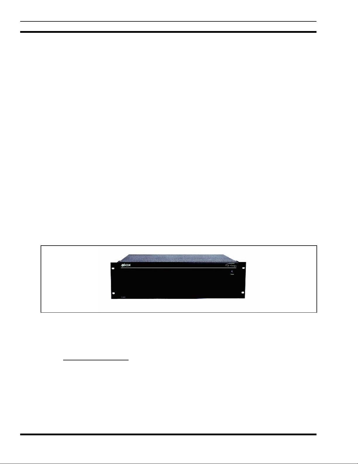
2.1 CS-7200 CONTROL STATION
The CS-7200 Control Station is a component of the OpenSky® network, an integrated voice and data
communications system that delivers end-to-end digital transmissions over a single wireless network to
various subscriber units.
The CS-7200 is used typically for dispatch purposes and operates over both the Specialized Mobile Radio
(SMR) and National Public Safety Planning Advisory Committee (NPSPAC) frequency bands. These
bands provide a total of over 830 possible channels spread over the 806-824 MHz transmission and 851869 MHz reception bands. The CS-7200 operates half-duplex voice, full duplex data, with a 15 W
(typical) transmit output power.
The CS-7200 uses Time Division Multiple Access (TDMA) technology to allow multiple users to share a
single RF channel. In addition, a single 20 kHz RF channel can support simultaneous digital voice and
data communications. The radio supports the OpenSky Trunked Protocol (OTP).
The CS-7200 provides voice and data services in a dispatch operation. Voice operation is provided using
the SP-103 Deskset or third-party Tone Remote Desk Sets via the TRCM-103. For data transfers, the CS7200 and the SP-103 are equipped with an industry standard TIA/EIA-232 interface serial port for
connecting optional equipment such as a laptop PC or third-party display or key-entry device. OpenSky
works seamlessly with equipment from popular manufacturers and off-the-shelf applications through a
standard UDP/IP Protocol, providing simple “plug and play” connectivity.
The CS-7200 is a “soft” radio. Its functions are determined by whatever release of OpenSky software
applications are installed. Refer to Figure 2-1 for a picture of the CS-7200.
2.2 MODES OF OPERATION
2.2.1 VOICE OPERATION
The voice path operates like a traditional dispatch radio, with a microphone to transmit (push-to-talk) and
a speaker to receive. In OpenSky Trunked Protocol (OTP), there is no separate voice and data path – all
transmitted information is digital.
Figure 2-1: CS-7200
8
2.2.2 DATA OPERATION
Data operation requires the connection of a laptop PC. OpenSky works through standard IP protocols
such as UDP/IP. The data path operates similarly to the voice path, with a few differences. All external
data information in and out of the radio uses the TIA/EIA-232 serial port connection.
2.2.3 INTERCOM OPERATION
The intercom option, a licensed option, allows the CS-7200 radio to pass audio locally between multiple
SP-103 units, not over the network. It gives users at multiple SP-103 units, connected to the same CS7200, the ability to communicate with each other without transmitting over-the-air. When activated,
incoming network radio calls are still scanned and broadcast at each SP-103 units.
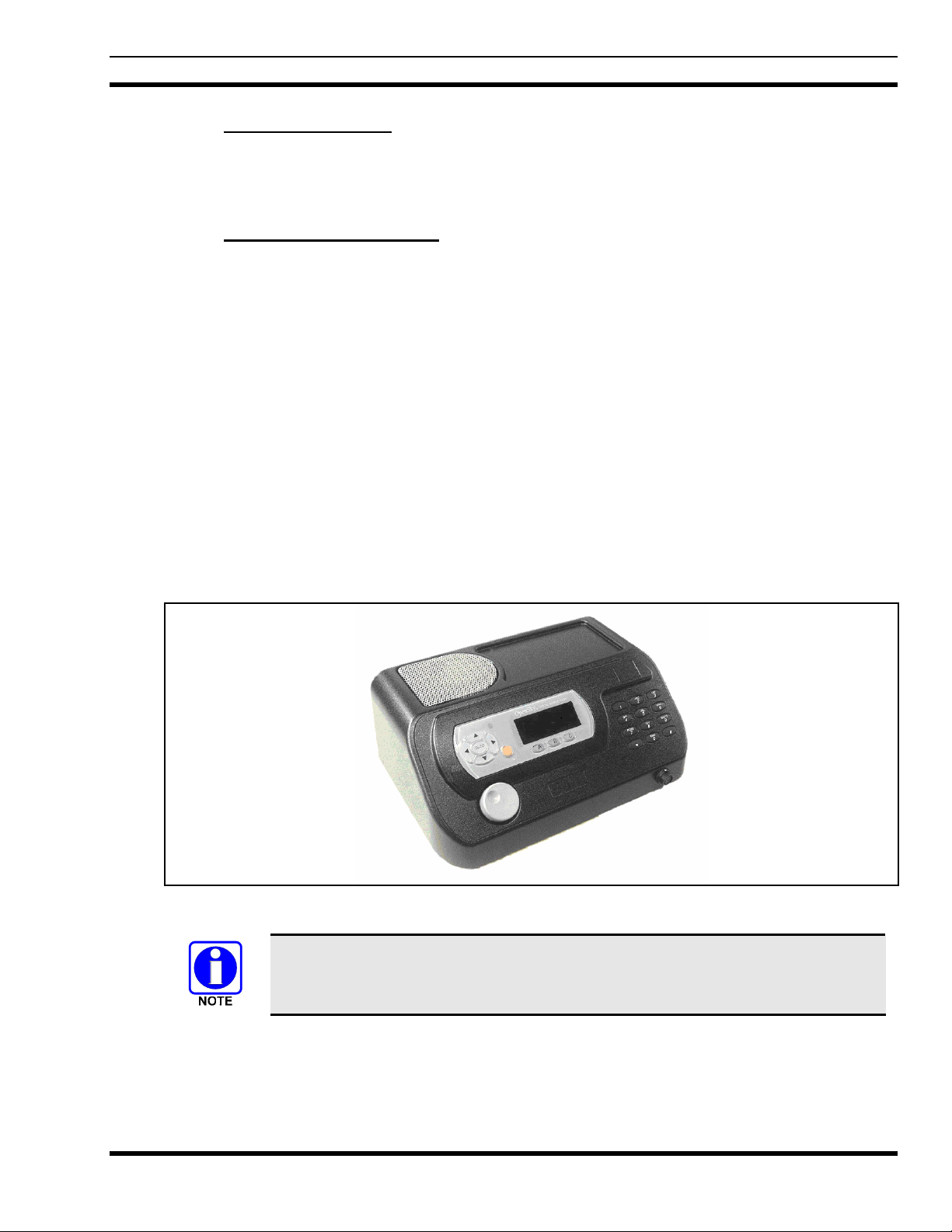
2.3 SP-103 DESKSET
The SP-103 Deskset is part of the OpenSky suite of radio products delivering high capacity, end-to-end,
digital communication and providing remote access for voice, data, and control of the CS-7200 Control
Station.
The SP-103 supports voice access via PTT microphones or headset microphones/speaker devices. The
SP-103 also provides an interface for a footswitch PTT in order to support microphones/headsets that do
not contain integral PTT switches. The SP-103 has an integral 3x4 DTMF keypad for log-on and selective
calling. The SP-103 contains an integral 10-Watt speaker and provides the interface to connect to an
external 10-Watt speaker. The serial port can be used for data operation. Refer to Figure 2-2 for a picture
of the SP-103.
MM-011709-001
Figure 2-2: SP-103 Deskset
Refer to Installation Manual MM-011712-001 when configuring the SP-103.
9
MM-011709-001
2.4 TRCM-103 TONE REMOTE CONTROL MODULE
The TRCM-103 operates within the OpenSky network as part of a Dispatch Center in conjunction with a
third-party Tone Remote Desk Set and CS-7200 Control Station. It provides remote voice and control
communication paths to the CS-7200. The TRCM-103 is a depot or field installed option that mounts on
the back of the CS-7200. The TRCM-103 automatically detects one of five alert tones and sixteen
function tones with a 26 dB dynamic range. The TRCM-103 audio interface utilizes a standard RJ-11 port
and is configurable for 2-wire half-duplex or 4-wire full-duplex operation. The TRCM-103 audio
termination is selectable for either 600 or 6k ohms. These features allow for easy integration with existing
Tone Remote Desk Sets. Please see the installation manual for details on configuring the device.
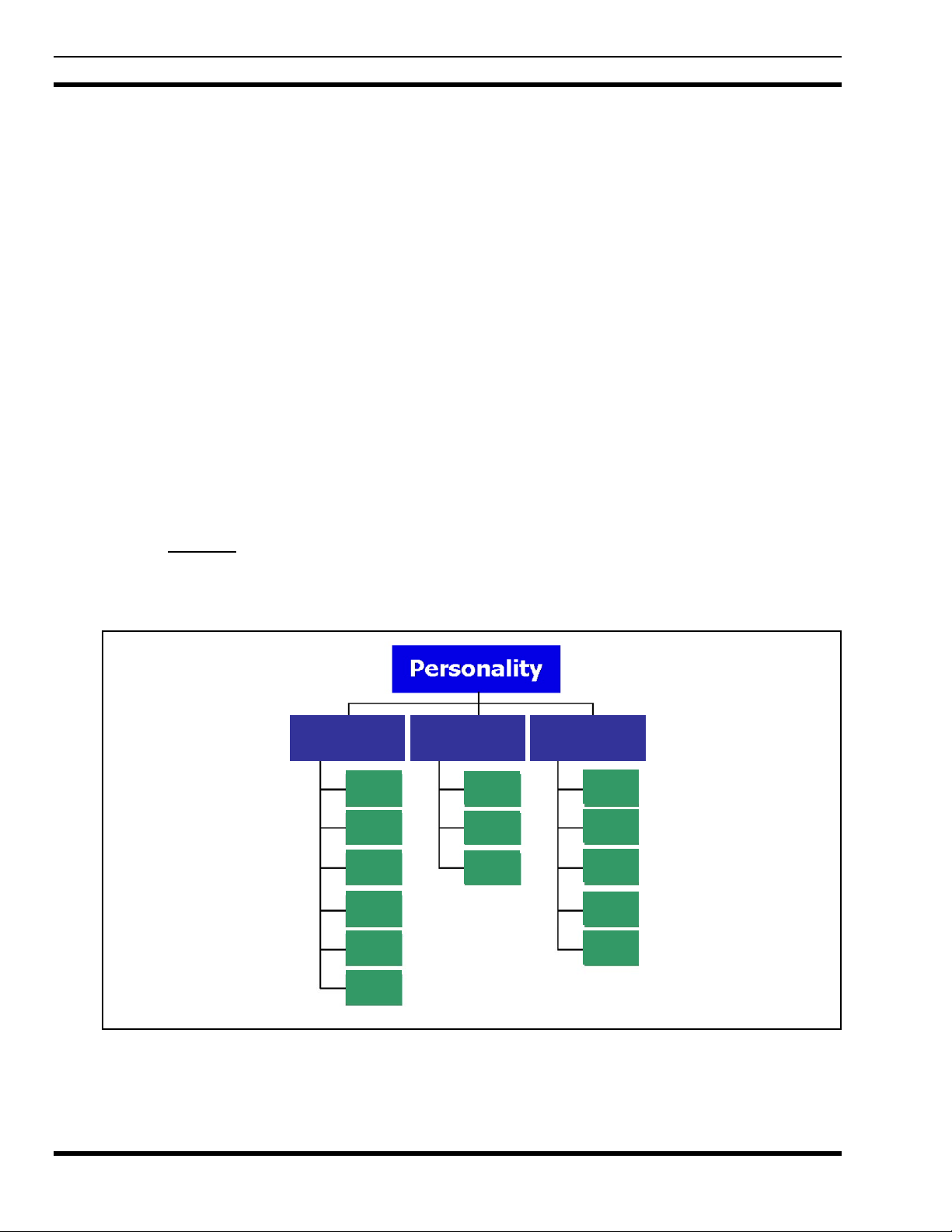
2.5 PERSONALITY
As illustrated in Figure 2-3, a personality defines the profiles and talk groups available to the user. It is
the structuring of a collection of profiles and privileges established by the OpenSky network administrator
to provide the user with a comprehensive set of profiles to communicate effectively with the necessary
talk groups or individuals.
Personalities are stored on the network and downloaded over-the-air to the CS-7200. This process is
called “provisioning.” Provisioning occurs at power-up and at user log-in. Each personality can contain
up to sixteen (16) profiles and each profile can contain up to sixteen talk groups.
2.5.1 Profiles
As stated above, each profile can contain up to sixteen (16) talk groups. A profile also defines emergency
behavior. All transmissions are made on the selected talk group (displayed on the top line of the dwell
display). The user can change the selected talk group to any of the other talk groups within the profile.
Profile 1 Profile 2 Profile 3
TG a
TG b
TG c
TG x
TG y
TG d
TG e
TG f
TG a
TG d
TG g
TG h
TG i
TG z
TG = Talk Group
10
Figure 2-3: Personality Structure Example

MM-011709-001
2.5.2 Talk Groups
A talk group represents a set of users that regularly need to communicate with one another. There can be
any number of authorized users assigned to a talk group. Talk groups are established and organized by the
OpenSky network administrator. An OpenSky talk group is similar to a channel within a conventional FM
radio system.
11
MM-011709-001
3 CS-7200/SP-103 OPERATION
3.1 CONTROLS AND INDICATORS
3.1.1 CS-7200 Front Panel
The CS-7200 front panel contains the mounting flanges, which allow for mounting into a standard 19”
rack. The power indicator light is located on the top right-hand side of the panel.
Figure 3-1: CS-7200 Front Panel
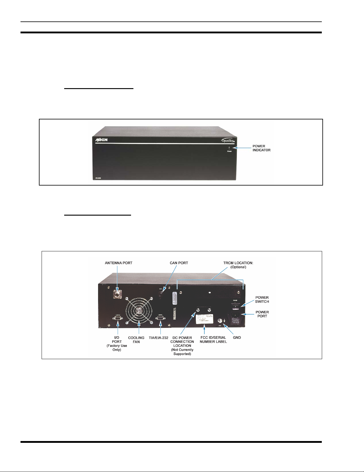
3.1.2 CS-7200 Rear Panel
The CS-7200 rear panel contains most of the cabling connections. The I/O connector contains radiospecific functions. A serial port is provided for connection to a standard TIA/EIA-232 (DTE) device.
Connection to a Controller Area Network (CAN) device, such as the SP-103 Deskset, or TRCM-103, is
made through the 3-pin CAN connector. The CS-7200 is a CAN termination end-point.
Figure 3-2: CS-7200 Rear Panel
12
3.1.2.1 TRCM-103
Installation of the TRCM-103 option allows the user to connect to off-the-shelf Tone Remote Desk Sets.
See Section 4 for TRCM-103 Operating Instructions.
MM-011709-001
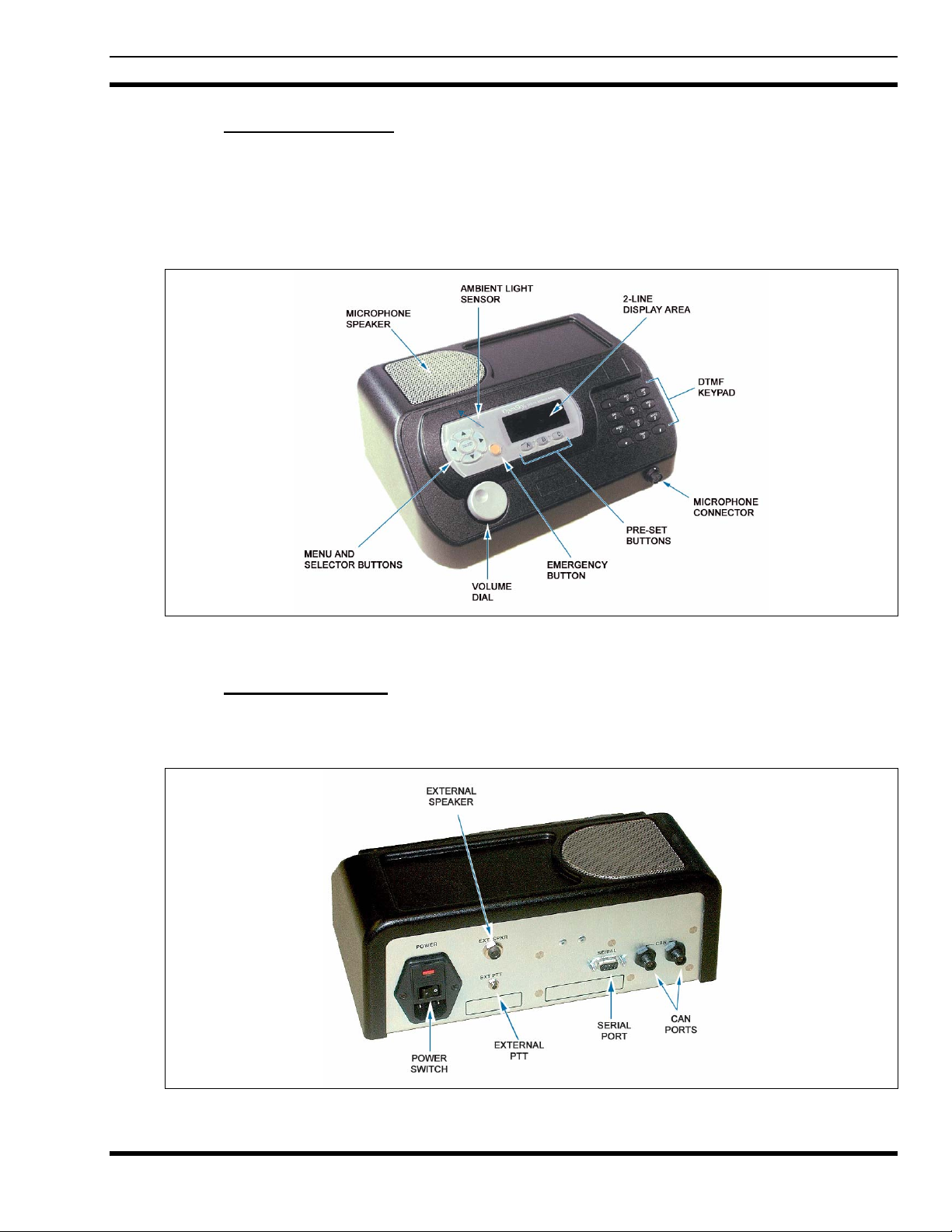
3.1.3 SP-103 Front Panel
The SP-103 front panel provides the CS-7200 user interface, which includes a 19-digit (8 over 11)
alphanumeric display panel, a menu and selector keypad, three pre-set buttons, a rotary volume control, a
microphone connector, emergency button, and 12-position DTMF keypad. In addition, the front panel
contains a photo-detector to sample ambient light level (used to automatically adjust display and button
backlighting brightness). See Table 3-1 for Controls and Functions overview.
Figure 3-3: SP-103 Front Panel
3.1.4 SP-103 Rear Panel
The SP-103 rear panel contains the interface connections necessary between the Deskset and the
CS-7200.
Figure 3-4: SP-103 Rear Panel
13
 Loading...