

Page 1
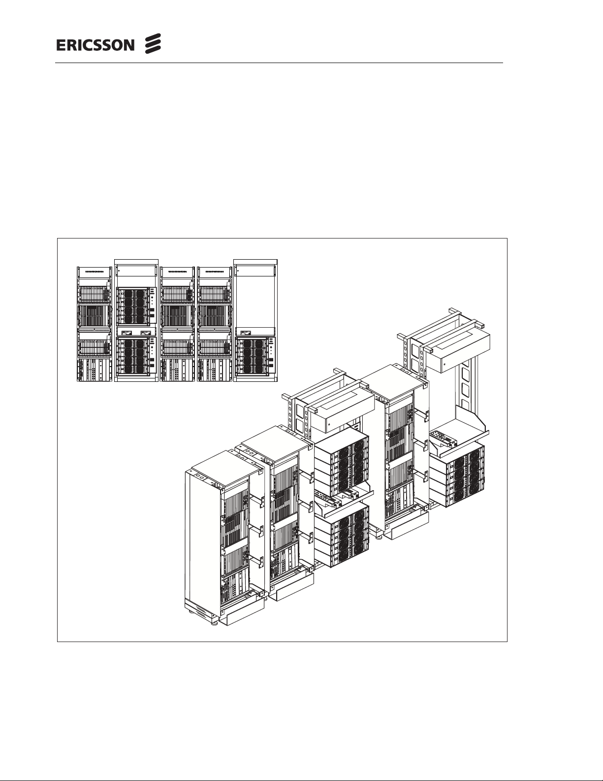
RBS 884 Macro with MCPA, 1900 MHz
PRELIMINARY User Guide (NOT FOR OPERATION)
PFCON
TRX TRX TRX TRX TRX TRX TRX TRX TRX TRX TRX TRX TRX TRX
POWER
POWER
POWER
POWER
POWER
POWER
POWER
POWER
POWER
ERROR
ERROR
ERROR
ERROR
ERROR
ERROR
ERROR
ERROR
ERROR
POWER
TATUSS
TATUSS
TATUSS
TATUSS
TATUSS
STATUS
TATUSS
TATUSS
ERROR
FAN
CID
24V
24V
Tx Out Tx Out Tx Out
TRX 1 TRX 2 TRX 3 TRX 4 TRX 5 TRX 6 TRX 7 TRX 8
PFCON 1
TCB
TRX 1
TRX 3
TRX 5
TRX 7
TRX 2
TRX 4
TRX 6
TRX 8
4 5
6 7
8 9
Pos 1 2 3
DC/DC
PFCON
TRX TRX TRX TRX TRX TRX TRX TRX TRX TRX TRX TRX TRX TRX
POWER
POWER
POWER
POWER
POWER
POWER
POWER
POWER
ERROR
ERROR
ERROR
ERROR
ERROR
ERROR
ERROR
ERROR
POWER
TATUSS
TATUSS
TATUSS
TATUSS
STATUS
TATUSS
TATUSS
ERROR
FAN
CID
24V
24V
Tx Out Tx Out Tx Out
TRX 1 TRX 2 TRX 3 TRX 4 TRX 5 TRX 6 TRX 7 TRX 8
PFCON 1
TCB
TRX 1
TRX 7
TRX 5
TRX 3
TRX 2
TRX 6
TRX 4
8 9
6 7
4 5
Pos 1 2 3
PFCON
DCON
TRX
PSP16TRX
DCON
POWER
POWER
POWER
POWER
POWER
POWER
POWER
POWER
POWER
PW
PW
ERROR
ERROR
ERROR
ERROR
ERROR
ERROR
ERROR
ERROR
ERROR
POWER
STATUS
S
TATUSS
TATUS
TATUS
TATUS
STATUS
TATUS
S
S
S
TATUSS
ERROR
CLINK
CLINK
FAN
MCB1
MCB3
CID
MCB2
MCB4
24V
CLINK
CLINK
ON OFF
MCA4
MCA2
MCA3
24V
SYNCout
SYNCout
Tx Out Tx Out Tx Out Tx Out Tx Out Tx Out Tx Out Tx Out Tx Out Tx Out Tx Out Tx Out Tx Out
MCA1
SYNCin
SYNCin
DCON 1
DCON 2 PFCON 2
PSP
TRX 9
TRX 11
TRX 13
TRX 15
ON OFF
TRX 10
TRX 12
TRX 14
TRX 16
10 11
12 13
14 15
16 17 18 19
20 21
DC/DC
ON OFF
ON OFF
PFCON
DCON
TRX
PSP16TRX
DCON
POWER
POWER
POWER
POWER
POWER
POWER
POWER
POWER
POWER
POWER
PW
PW
ERROR
ERROR
ERROR
ERROR
ERROR
ERROR
ERROR
ERROR
ERROR
ERROR
POWER
STATUS
S
TATUSS
TATUS
TATUS
TATUSS
TATUS
STATUS
TATUS
S
S
S
TATUSS
ERROR
CLINK
CLINK
FAN
MCB1
ON OFF
MCB3
CID
MCB2
MCB4
24V
CLINK
CLINK
MCA4
MCA2
MCA3
24V
SYNCout
SYNCout
Tx Out Tx Out Tx Out Tx Out Tx Out Tx Out Tx Out Tx Out Tx Out Tx Out Tx Out Tx Out Tx Out
MCA1
ON OFF
SYNCin
SYNCin
DCON 2 PFCON 2
DCON 1
PSP
TRX 15
TRX 13
TRX 11
TRX 9
TRX 16
TRX 14
TRX 12
TRX 10
TRX 8
16 17 18 19
20 21
14 15
12 13
10 11
ON OFF
ON OFF
1234
AMPLIFIER
1234
AMPLIFIER
1234
AMPLIFIER
1234
AMPLIFIER
PFCON
TRX TRX TRX TRX TRX TRX TRX TRX TRX TRX TRX TRX TRX TRX
POWER
POWER
POWER
POWER
POWER
POWER
POWER
POWER
POWER
ERROR
ERROR
ERROR
ERROR
ERROR
ERROR
ERROR
ERROR
ERROR
POWER
TATUSS
TATUSS
TATUSS
TATUSS
TATUSS
STATUS
TATUSS
TATUSS
ERROR
FAN
CID
24V
24V
Tx Out Tx Out Tx Out
TRX 1 TRX 2 TRX 3 TRX 4 TRX 5 TRX 6 TRX 7 TRX 8
PFCON 1
TCB
TRX 1
TRX 3
TRX 5
TRX 7
TRX 2
TRX 4
TRX 6
TRX 8
4 5
6 7
8 9
Pos 1 2 3
DC/DC
PFCON
TRX TRX TRX TRX TRX TRX TRX TRX TRX TRX TRX TRX TRX TRX
POWER
POWER
POWER
POWER
POWER
POWER
POWER
POWER
ERROR
ERROR
ERROR
ERROR
ERROR
ERROR
ERROR
ERROR
POWER
TATUSS
TATUSS
TATUSS
TATUSS
STATUS
TATUSS
TATUSS
ERROR
FAN
CID
24V
24V
Tx Out Tx Out Tx Out
TRX 1 TRX 2 TRX 3 TRX 4 TRX 5 TRX 6 TRX 7 TRX 8
PFCON 1
TCB
TRX 1
TRX 7
TRX 5
TRX 3
TRX 2
TRX 6
TRX 4
8 9
6 7
4 5
Pos 1 2 3
PFCON
PFCON
TRX TRX TRX TRX TRX TRX TRX TRX TRX TRX TRX TRX TRX TRX
POWER
POWER
POWER
POWER
POWER
POWER
POWER
POWER
POWER
POWER
ERROR
ERROR
ERROR
ERROR
ERROR
ERROR
ERROR
ERROR
ERROR
ERROR
POWER
TATUSS
TATUSS
TATUSS
TATUSS
TATUSS
TATUSS
STATUS
TATUSS
TATUSS
ERROR
FAN
CID
24V
24V
Tx Out Tx Out Tx Out
TRX 1 TRX 2 TRX 3 TRX 4 TRX 5 TRX 6 TRX 7 TRX 8
PFCON 1
TRX 1
TRX 3
TRX 5
TRX 7
TRX 9
TRX 2
TRX 4
TRX 6
TRX 8
4 5
6 7
8 9
10 11
DC/DC
PFCON
TRX TRX TRX TRX TRX TRX TRX TRX TRX TRX TRX TRX TRX TRX
POWER
POWER
POWER
POWER
POWER
POWER
POWER
POWER
POWER
POWER
ERROR
ERROR
ERROR
ERROR
ERROR
ERROR
ERROR
ERROR
ERROR
ERROR
POWER
TATUSS
TATUSS
TATUSS
TATUSS
TATUSS
TATUSS
STATUS
TATUSS
TATUSS
ERROR
FAN
CID
24V
24V
Tx Out Tx Out Tx Out
TRX 1 TRX 2 TRX 3 TRX 4 TRX 5 TRX 6 TRX 7 TRX 8
PFCON 1
TRX 9
TRX 1
TRX 7
TRX 5
TRX 3
TRX 2
TRX 8
TRX 6
TRX 4
10 11
8 9
6 7
4 5
PFCON
DCON
TRX
PSP16TRX
DCON
POWER
POWER
POWER
POWER
POWER
POWER
POWER
POWER
PW
PW
ERROR
ERROR
ERROR
ERROR
ERROR
ERROR
ERROR
ERROR
POWER
STATUS
S
TATUS
TATUS
TATUS
STATUS
TATUS
S
S
S
TATUSS
ERROR
CLINK
CLINK
FAN
MCB1
MCB3
CID
MCB2
MCB4
24V
CLINK
CLINK
MCA4
MCA2
MCA3
24V
SYNCout
SYNCout
Tx Out Tx Out Tx Out Tx Out Tx Out Tx Out Tx Out Tx Out Tx Out Tx Out Tx Out Tx Out Tx Out
MCA1
SYNCin
SYNCin
DCON 1
DCON 2 PFCON 2
PSP
TRX 11
TRX 13
TRX 15
TRX 10
TRX 12
TRX 14
TRX 16
12 13
14 15
16 17 18 19
20 21
DC/DC
PFCON
DCON
TRX
PSP16TRX
DCON
POWER
POWER
POWER
POWER
POWER
POWER
POWER
POWER
PW
PW
ERROR
ERROR
ERROR
ERROR
ERROR
ERROR
ERROR
ERROR
POWER
STATUS
S
TATUS
TATUS
TATUS
STATUS
TATUS
S
S
S
TATUSS
ERROR
CLINK
CLINK
FAN
MCB1
ON OFF
MCB3
CID
MCB2
MCB4
24V
CLINK
CLINK
MCA4
MCA2
MCA3
24V
SYNCout
SYNCout
Tx Out Tx Out Tx Out Tx Out Tx Out Tx Out Tx Out Tx Out Tx Out Tx Out Tx Out Tx Out Tx Out
MCA1
ON OFF
SYNCin
SYNCin
DCON 2 PFCON 2
DCON 1
PSP
TRX 15
TRX 13
TRX 11
TRX 16
TRX 14
TRX 12
TRX 10
16 17 18 19
20 21
14 15
12 13
1234
ON OFF
AMPLIFIER
1234
AMPLIFIER
ON OFF
DCON
TRX
PSP16TRX
DCON
POWER
POWER
POWER
POWER
POWER
POWER
POWER
POWER
POWER
PW
PW
ERROR
ERROR
ERROR
ERROR
ERROR
ERROR
ERROR
ERROR
ERROR
POWER
STATUS
S
TATUSS
TATUS
TATUS
TATUS
STATUS
TATUS
S
S
S
TATUSS
ERROR
CLINK
CLINK
FAN
MCB1
MCB3
CID
MCB2
MCB4
24V
CLINK
CLINK
MCA4
MCA2
MCA3
24V
SYNCout
SYNCout
Tx Out Tx Out Tx Out Tx Out Tx Out Tx Out Tx Out Tx Out Tx Out Tx Out Tx Out Tx Out Tx Out
MCA1
SYNCin
SYNCin
DCON 1
DCON 2 PFCON 2
TCB
PSP
TRX 9
TRX 11
TRX 13
TRX 15
TRX 10
TRX 12
TRX 14
TRX 16
10 11
12 13
14 15
16 17 18 19
20 21
Pos 1 2 3
DC/DC
PFCON
DCON
TRX
PSP16TRX
DCON
POWER
POWER
POWER
POWER
POWER
POWER
POWER
POWER
POWER
POWER
PW
PW
ERROR
ERROR
ERROR
ERROR
ERROR
ERROR
ERROR
ERROR
ERROR
ERROR
POWER
STATUS
S
TATUSS
TATUS
TATUS
TATUSS
TATUS
STATUS
TATUS
S
S
S
TATUSS
ERROR
CLINK
CLINK
FAN
MCB1
MCB3
CID
MCB2
MCB4
24V
CLINK
CLINK
MCA4
MCA2
MCA3
24V
SYNCout
SYNCout
Tx Out Tx Out Tx Out Tx Out Tx Out Tx Out Tx Out Tx Out Tx Out Tx Out Tx Out Tx Out Tx Out
MCA1
SYNCin
SYNCin
DCON 2 PFCON 2
DCON 1
TCB
PSP
TRX 15
TRX 13
TRX 11
TRX 9
TRX 16
TRX 14
TRX 12
TRX 10
TRX 8
16 17 18 19
20 21
14 15
12 13
10 11
Pos 1 2 3
1234
AMPLIFIER
ON OFF
1234
AMPLIFIER
ON OFF
ON OFF
ON OFF
1234
AMPLIFIER
ON OFF
1234
AMPLIFIER
ON OFF
ON OFF
ON OFF
1234
AMPLIFIER
ON OFF
1234
AMPLIFIER
ON OFF
ON OFF
ON OFF
AE/LZB 119 4239 PRELIM 2001-03-15 © Ericsson Radio Systems AB 2000 – All Rights Reserved
Page 2

The contents of this document are subject to revision without notice due to
continued progress in methodology, design, and manufacturing.
Ericsson shall have no liability for any error or damages of any kind resulting
from the use of this document.
i 001 52-AE/LZB 119 4239 Uae Rev PRELIM 2001-03-15
Page 3

Table of Contents
Part1 Introduction ...................... 1-1
1 ReasonforReissue ............... 1-3
2 AboutthisUserGuide .............. 1-3
3 HowtoUseTheUserGuide ........... 1-4
Part2 GeneralProductInformation .............. 2-1
1 Introduction ................... 2-3
2 Features .................... 2-3
3 ProductLines .................. 2-4
Part3 SystemDescription ................... 3-1
1 Introduction ................... 3-3
2 SystemArchitecture ............... 3-4
3 RBSOverview .................. 3-8
4 EquipmentConfiguration ............. 3-19
5 EquipmentDescription .............. 3-21
6 TechnicalSpecifications ............. 3-36
001 52-AE/LZB 119 4239 Uae Rev PRELIM 2001-03-15 ii
Page 4

Contents
iii 001 52-AE/LZB 119 4239 Uae Rev PRELIM 2001-03-15
Page 5

List of Figures
Figure Title Page
Figure 2-1 Product Line s in the R BS 884 Series . . . . . . . . 2-4
Figure 3-1 1900 MHz Sub-Band Spectrum . . . . . . . . . . 3-4
Figure 3-2 General Overview of RBS 884 Configuration . . . . 3-5
Figure 3-3 General Overview of RBS 884 Configuration . . . . 3-6
Figure 3-4 Block Diagra m of a Radio Base Station . . . . . . . 3-7
Figure3-5 MacrowithMCPA,1900MHz ........... 3-9
Figure 3-6 CRI and TCB Functional Block Diagram . . . . . . 3-10
Figure 3-7 HCC and ANPC FunctionalBlock Diagram . . . . 3-11
Figure 3-8 Macro with MCPA, 1900 MHz Receive Path . . . . 3-12
Figure 3-9 Macro with MCPA, 1900 MHz Transmit Path . . . . 3-13
Figure 3-10 Macro with MCPA, 1900 MHz Synchronization . . . 3-15
Figure 3-11 3x15 CRI-PCM (T1)Configuration . . . . . . . . 3-17
Figure 3-12 3x24 CRI-PCM (T1)Configuration . . . . . . . . 3-18
Figure 3-13 3x31 CRI-PCM (T1)Configuration . . . . . . . . 3-19
Figure 3-14 Typical Macro with MCPA, 1900 MHz Configuration . 3-20
Figure 3-15 Macro with MCPA, 1900 MHz Equipment (Omni-site) 3-23
Figure3-16 CRIBoardLayout ............... 3-24
Figure 3-17 Macro with MCPA, 1900 MHz TCB . . . . . . . . 3-27
Figure 3-18 Macro with MCPA, 1900 MHz ANPC . . . . . . . 3-29
Figure3-19 HybridCombinerUnit ............. 3-30
Figure3-20 TXBPandMCU ............... 3-31
Figure 3-21 MCPA Rack and Amplifier Modules . . . . . . . 3-32
Figure 3-22 RBS Power Distribution Cabinet . . . . . . . . . 3-34
Figure 3-23 MCPA Power Distribution Cabinet . . . . . . . . 3-35
001 52-AE/LZB 119 4239 Uae Rev PRELIM 2001-03-15 iv
Page 6

Contents
v 001 52-AE/LZB 119 423 9 Uae Rev PRELIM 200 1-03-15
Page 7

List of Tables
Table Title Page
Table 3-1 POWD Circuit BreakerAssignments . . . . . . . 3-33
Table 3-2 POWD Circuit BreakerAssignments . . . . . . . 3-34
Table 3-3 Macro with MCPA, 1900 MHz Technical Specifications
Table 3-4 Macro with MCPA, 1900 MHz Technical Specifications
....................... 3-36
....................... 3-38
001 52-AE/LZB 119 4239 Uae Rev PRELIM 2001-03-15 vi
Page 8

Contents
vii 001 52-AE/LZB 119 4239 Uae Rev PRELIM 2001-03-15
Page 9

Part 1
Introduction
001 59-AE/LZB 119 4239 Uae Rev PRELIM 2001-03-15 1-1
Page 10

Introduction
1-2 001 59-AE/LZB 119 4239 Uae Rev PRELIM 2001-03-15
Page 11

This section describes the information c onta ine d in the manual and the
conventions used in its presentation.
1 Reason for Reissue
This is the first issue of this user guide.
2 A bout this User Guide
The target audience for the user guide is Radio Base Station (RBS) site
installation, site testing, and site maintenance personnel.
This manual contains the information required to install, troubleshoot, and
maintain the RBS 884 Macro with MCPA, 1900 MHz hardware.
Introduction
2.1 User Guide Contents
It is assumed that before the user guide is used to pe rform any activities at a
radio base station s ite, telephone transmission facilities, alternating current
(AC) electrical line power, and groun ding have been made available. Ensure
the antenna system is installed.
When the radio base sta tion equipment has been installed using the
information i n this manual, it will be left powered up ready for integr ation
into the network by personnel at the Mobile Services Switching Center
(MSC).
This user guide is divided into the following parts:
• Introduction – a description of the contents of the manual and how
the manual can be used.
• General Product Information – a description of the various systems,
platforms, and enclosures w it hin the RBS 884 family of Radio
Base Stations.
• System Description – a description of the hardware and functions of
the RBS 884 Macro with MCPA, 1900 MH z equipment.
• Installation – procedures for the installation of the RBS equipment
on the site.
• Administration – procedure s for
001 59-AE/LZB 119 4239 Uae Rev PRELIM 2001-03-15 1-3
Page 12

Introduction
• Integration and Verification– procedures for
• Operations and Maintenance– procedures for
• Troubleshooting – provides LED indications.
• Hardware Replacement – procedures for basic troubleshooting and
replacement of equipment suspected to be faulty.
• Glossary of Terms – definitions of key terms used in the ma nual.
• Acronyms and Abbreviations – expanded versions of all of the
acronyms and abbreviations used in the manual.
• Appendix A, RF Guidelines.
• Appendix B, Documentation Overview.
• Appendix C, User Feedback.
• Appendix D, Conversion Table
Many of the procedures in the user guide require site-specific data from the
Site Inst allation Documentation relating to the particular radio base station
site where the installation i s to take place. This docum entation should be
available at the site.
The procedures in the user guide for installation and maintenance are
normally intended to be performed sequentially, in the order p resented.
3 How to Use The User Guide
This user’s guide contains information required to install, test, operate, and
troubleshoot the RBS 884 Macro with MCPA, 1900 MHz system. Prior to
beginning a specific task or operation, do the following:
• Read the related Part or Appendix.
• Verify that all required materials and tools are available.
• Observe all dangers, warnings, and cautions for the task or operation.
The following document conventions apply to this user’s guide:
admonishments and typefaces. The admonishments alert the user to
hazardous or damaging actions. The typefaces emphasize text to enhance
the use of this user guide.
1-4 001 59-AE/LZB 119 4239 Uae Rev PRELIM 2001-03-15
Page 13

Introduction
• Admonishm e nts
– Danger indicates that death or critical injury to the person
or persons performing a task can result if procedures are not
followed correctly.
– Warning indicates that equipment can be seriously damaged,
resulting in equipment or system failure or service interruption,
if procedures are not followed correctly.
– Caution ind icates potential damage to the equipment, system, or
data if procedures are not followed correctly.
• Typefaces
Typeface indicates software menu selections that must be typed
(entered) by the user.
– Bold typeface emphasizes headings, admonishments,
trademarks, and examples of command names.
– Italics typeface indicates a reference to additional in formatio n
provided in another section or document.
001 59-AE/LZB 119 4239 Uae Rev PRELIM 2001-03-15 1-5
Page 14

Introduction
1-6 001 59-AE/LZB 119 4239 Uae Rev PRELIM 2001-03-15
Page 15

Part 2
General Product Information
1 Introduction .................. 2-3
2 Features .................... 2-3
3 ProductLines .................. 2-4
3.1 RBS884Macro ............. 2-5
3.2 RBS884Micro .............. 2-6
1/1551 AE/LZB 119 4239 Uae Rev PRELIM 2001-03-15 2-1
Page 16

General Product Information
2-2 1/1551 AE/LZB 119 4239 Uae Rev PRELIM 2001-03-15
Page 17

1 Introd uction
The General Product Information provides general information on
unconfigured radio base stations. Refer to the RBS 884 Site Engineering
Manual for descriptions of the available working ba se station configurations
and for information on RBS interfaces (for instance, power, transmission,
and antennas).
2 Features
The RBS 884 Series is a series of products in the CMS 8800 f ami ly. The
products in the RBS 884 Series are f ully featured modular RBSs for both
the analog AMPS EIA 553 and the digital D-AMPS EIA I S 136 systems
(Advanced M obile Phone System Electronics Industry Association 553
system and Digital American M obile Phone System Electronics Industry
Association Interim Standard 136 system).
General Product Information
A base station in the RBS 884 Series can s upport one, two, or three cells. A
cell is a defined area covered by one antenna system, and each cell has one
control channel for digital or one for analog, or both. There is one cell at an
omni site, and one to three cells at a sectorized site.
The RBS 884 Series utilizes multi-mode, multi-functional transceivers
(TRXs). The same hardware TRX module can be used for analog and digital
voice, contr ol and monitoring purposes.
The hot repair capability allows replacement of defective units when power
is still applied.
The RBS 884 Series is designed for remote control monitoring allowing
control and fine tuning of all functions and parameters, such as power output,
frequencies, and switching of redundant units from the M SC.
A Radio Frequency Test Loop (RFTL) is an optional feature that enables
precise output power settings, Voltage Standing Wave Ratio (VSWR) alarm,
and Receive Signal Strength Indicator (RSSI) test measurements.
The device software is stored in non-volatile memory within the RBS, and
the control part software is downloaded f rom the MSC, which ensures a
short time to service at power-up.
1/1551 AE/LZB 119 4239 Uae Rev PRELIM 2001-03-15 2-3
Page 18
General Product Information
3 Product Lines
RBS 884 Macro
with MCPA,
850 MHz
RBS 884 Micro
(1900 MHz)
RBS 884 Outdoor
RBS 884
RBS 884 Macro
with MCPA, 1900 MHz
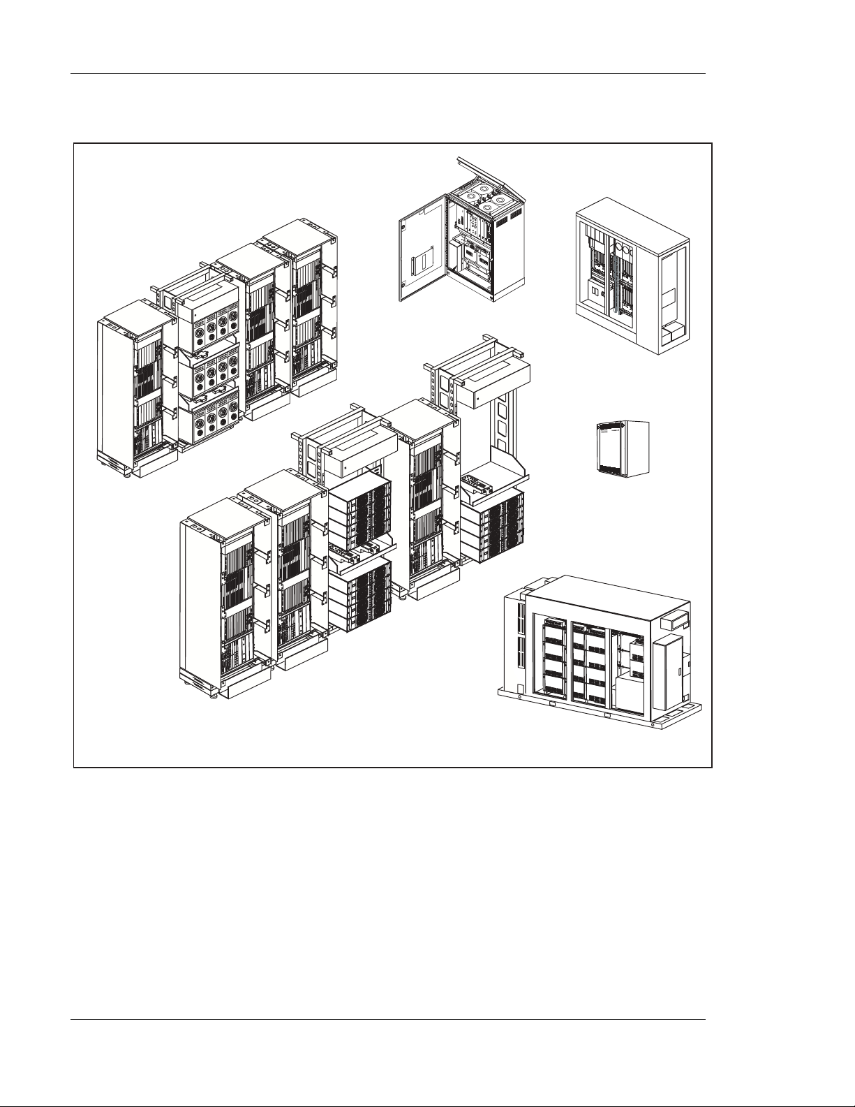
Figure 2-1. Product Lines in the RBS 8 84 Series
1234
AMPLIFIER
ON OFF
1234
AMPLIFIER
ON OFF
ON OFF
ON OFF
1234
AMPLIFIER
ON OFF
1234
AMPLIFIER
ON OFF
ON OFF
ON OFF
1234
AMPLIFIER
ON OFF
1234
AMPLIFIER
ON OFF
ON OFF
ON OFF
RBS 884
Micro 800
RBS 884
High Capacity
Self-Contained Cell Site
2-4 1/1551 AE/LZB 119 4239 Uae Rev PRELIM 2001-03-15
Page 19

The RBS 884 Series includes product lines for macro and micro cells. See
Figure 2-1 on page 2-4.
Note: The maximum number of carriers for each sector stated is the
3.1 RBS 884 Macro
The macro cell products are intended for normal indoor installations and are
built on-site with a number of cabinets of uniform size and design.
The RBS 884 Macro 850 MHz supports TDMA. This s ystem operates
at 824–894 MHz and provides up to 78 low power or medium power
transceivers (3x24 carriers), or up to 96 high power and 6 low power
transceivers (3x32 carriers).
General Product Information
technical limitation for the defined standard configurations. The
practical usable sector sizes may be limited by the frequency
plan. The capacity of all product lines, wit h the exception of the
RBS 884 Micro (1900 MHz) is calculated for analog systems.
The capacity of the RBS 884 Micro (1900 MHz) is calculated for
digital systems. See the integration information in the RBS 884
Operations and Maintenance Manual for system limitations in
digital systems.
The RBS 884 Macro 1900 MHz supports TDMA and operates at 1850–1990
MHz (A-, B-, or C-band). It provides up to 48 medium po wer transceivers
(3x15 carriers).
A special configuration, High-Capacity Self Contained Cell Site (HC-SCCS),
providing up to 31 transceivers in three sectors (3x31 carriers), can be
installed in an outdoor container.
The RBS 884 Macro DBC (Down Banded Cellular) supports TDMA and
is applicable to frequencies at 806–860 MHz. Up to 39 medium power
transceivers (3x12 carriers) can be used in one installation.
The RBS 884 Macro PACS (4-High) is an RBS 884 Macro Pre-Assembled
Cell Site ( PACS) that supports 1900 MHz and 850 MH z TDMA using
single-sector (omni-site) modules. Multi-sector systems can be configured
using two or three omni-site modules. Each module consists of two racks
with f our cabinets in each rack. The Macro PACS (4-High) system is
available in 1900 MHz medium power, 1900 MHz QUAD, 850 MHz
medium power, and 850 MHz high power.
The RBS 884 Macro with MCPA is an RBS 884 Macro Pre-Assembled
Cell Site ( PACS) that supports 1900 MHz and 850 MH z TDMA using
single-sector (omni-site) modules. The system uses a hybrid combiner and
multi-carrier power amplifiers. Multi-sector systems can be configured using
two or three omni-site RBS modules.
1/1551 AE/LZB 119 4239 Uae Rev PRELIM 2001-03-15 2-5
Page 20

General Product Information
3.2 RBS 884 Micro
The RBS 884 Micro products are used wherever local capacity or coverage is
required.
The RBS 884 Micro 850 MHz is intended for indoor installation, and typical
applications include convention centers, office buildings, parking areas and
tunnels. The RBS 884 Micro comprises one small main cabinet and two
possible expansion cabinets of the same size. It is a completely functional
cell, with a drop and inse rt transmission interface and RF equipment built-in.
Up to 10 1.5W transceivers can be used in one cabinet (8 carriers). Up to
30 tr ansceivers can be provided with two auxiliary cabinets (24 c arriers).
This gives a total capab ility of up to 23 analog or 68 digital voice channels
(71 with E1 PCM links).
The RBS 884 Micro with Multi Carrier Power Amplifier ( MCPA) (850
MHz) supports TDMA and operates at 824–894 MHz. It is a standard RBS
884 Micro (850 MH z) equipped with a MCPA for higher output power in one
cell. The MC PA is a separate cabinet mounted below the RBS 8 84 Micro
(850 MHz) cabinet. Up to three RBS 884 Micro (850 MHz) cabinets and one
MCPA can be mounted in a 19-inch rack cabinet. An RBS 884 Micro with
MCPA (850 MHz) can provide up to 23 analog or 68 digital voice channels
(71withE1PCMlinks)inonecell.
The RBS 884 M icro Outdoor (85 0 MHz) supports TDMA and operates at
824–894 MHz. Designed for outdoor use, it is contained in an all-weather
steel enclosure with an environmentally-controlled interior and can be
installed in a wide variety of locations and climatic zones. The RBS 884
Micro (850 MHz) can be provided with up to 26 transceivers and a total of
24 carriers. T his provides a total capacity of up to 23 analog or 68 digital
voice channels (71 with E1 PCM links).
The RBS 884 Micro (1900 MHz) supports TDMA and operates at
1850–1910 MHz. The RBS 884 Micro (1900 MHz) is a self-contained base
station intended primarily for outdoor use. The cabinet is cooled directly with
outdoor air, using a combination of variable speed blowers and a variable
power heater to maintain the cabinet air temperature within equipment
operating limits. Typical applications include hot spot areas within mature
1900 MHz networks and areas not covered by the RBS 884 Macro. The RBS
884 Micro (1900 MHz) is comprised of one small main cabinet and up to
two auxiliary primary cabinets of the same size. The cabinets can be easily
mounted on poles, on the sides of buildings, on rooftops, or on concrete
pads. The RBS 884 Micro (1900 MHz) is a complete functional cell, with
a drop and insert transmission interface and built -in RF equipment. Up to
5 transceivers can be used in one cabinet providing 4 carriers. Up to 15
transceivers can be used in a three-cabinet installation providi ng 3x4 carriers.
The three-cabine t installation allows up to 33 d igital traffic channels.
2-6 1/1551 AE/LZB 119 4239 Uae Rev PRELIM 2001-03-15
Page 21

Part 3
System Description
1 Introduction .................. 3-3
2 SystemArchitecture .............. 3-4
3 RBSOverview ................. 3-8
3.1 FunctionalOverview ........... 3-8
3.2 CallPaths ................ 3-12
3.3 Signaling ................. 3-13
3.4 Synchronization ............. 3-15
3.5 CRI and PCM Link Configuration (T1) . . . 3-16
4 EquipmentConfiguration ............ 3-19
5 EquipmentDescription ............. 3-21
5.1 Control Radio Interface Cabinet (CR I) . . . 3-23
5.2 TransceiverCabinet(TCB) ........ 3-26
5.3 An tenna Near Part Cabinet (ANPC) . . . . 3-28
5.4 HybridCombiner ............. 3-30
5.5 Transmit Bandpass Filter (TXBP) . . . . . 3-31
5.6 Measurement Coupler Un it (MCU) . . . . . 3-31
5.7 Multi-Carrier Power Amplifier (MC PA) . . . 3-32
5.8 RBS P ower Distribution Cabine t (POW D) . . 3-33
5.9 MC PA Power Distribution Cabinet
(HC-POWD) ............... 3-34
6 TechnicalSpecifications ............ 3-36
6.1 Ele ctrical and RF Specifications . . . . . . 3-36
6.2 Mechanical and Environmental
Specifications .............. 3-38
2/1551-AE/LZB 119 4239 Uae Rev A 2001-03-15 3-1
Page 22

System Description
3-2 2/1551-AE/LZB 119 4239 Uae Rev A 2001-03-15
Page 23

1 Introd uction
This section provides an overview of the RBS 884 Macro with M CPA, 1900
MHz radio base station (RBS). Areas covered include system architecture,
configuration, functional units and technical specifications.
This RBS supports digital TDMA a nd operates at 1850–1990 MHz (divided
into 6 sub-bands) and is part of the Mobile Base Station (MBS) subsystem. It
handles the communication between a Mobile Switching Center (MSC) and
Mobile Stations (MSs). This radio base station also supervises the quality of
radio transmission during a call in progress. The MBS consists of hardware
and software located in the MSC as well as in the RBS.
The Macro with MCPA , 1900 MHz system is available in the following
configurations:
System Description
• 1, 2, and 3 Sector x 15 carriers
• 1, 2, and 3 Sector x 23 carriers
• 1, 2, and 3 Sector x 31 carriers
2/1551-AE/LZB 119 4239 Uae Rev A 2001-03-15 3-3
Page 24

System Description
A BC
1900 MHz Uplink Sub-bands
DEF
1850
1865
1900 MHz Downlink Sub-bands
DEF
A BC
1930
Figure 3-1. 1900 MHz Sub-Band Spectrum
1945
1870
1950
1885
1965
1890
1970
1895
1975
1910
1990
2 System Architecture
The Macro with MCPA, 1900 MH z controls and handles communication
between the MSC and the mobile stations. The configur ation of the
equipment in a specific system depends on the following:
• Number of sectors
• Number of voice channels in each sector
• Transmit power
3-4 2/1551-AE/LZB 119 4239 Uae Rev A 2001-03-15
Page 25

• Number and type of antennas
• System mode (analog, digital, or both)
System Description
MSC
Figure 3-2 on page 3-5 shows the m
PCM Links
Radio
Base
Station
Antennas
ain RBS connections.
Sector A
TX
RX RX
Sector B
TX
RX RX
Sector C
TX
RX RX
Figure 3-2. General Overview of RBS 884 Configuration
Figure 3-3 on page 3-6 shows the primary components of the MSC and RBS.
2/1551-AE/LZB 119 4239 Uae Rev A 2001-03-15 3-5
Page 26

System Description
MSC
Public
Switched
Telephone
Network
Figure 3-3. General Overview of RBS 884 Co nfiguration
Group
Switch
Central
Processor
The Group Switch (GS) attheMSCisresponsible for switching calls between
subscriber terminals. The calls can be between two mobile subscribers
or between a mobile subscriber and a subscriber in the public telephone
network. The RBS contains several regional processors which are controlled
by and work w ith the central processor. The regional processors control the
switch and the transceivers (TRXs) in the base station. The switch in the base
station ensures the speech signals from the M SC are connected to the correct
TRX. The TRXs generate RF that is emitted by the base station antenna to
the mobile term inals. The semipermanent connections are set up in the MSC.
Switch
Regional
Processors
RBS
Transceivers
Mobile
Terminals
Figure 3-4 on page 3-7 shows the logical parts of an RBS.
3-6 2/1551-AE/LZB 119 4239 Uae Rev A 2001-03-15
Page 27

System Description
Radio Base
Station (RBS)
Rx
Antenna Near Part
- Filters
- Multi-Coupler (Rx amplifier)
- Combiners (one Tx antenna per sector)
- Test and calibration
Modem Part
- Converts speech and data to RF
- Power Splitters for RF input
- Tranceiver Units (TRXs)
Control Part
- MSC/traffic control communication
- Remote Multiplexer (terminates PCM)
- Signal Terminal (decodes control info)
- EMRPs (control TRXs)
Tx
Support Part
Power distribution, fans, external alarms
Mobile Switching Center (MSC)
Figure 3-4. Block Diagram of a Radio Base Station
The logical parts of the RBS 884 Macro are as follows:
• Control Part (COP) – provides communication between the MSC
and the RBS hardware for radio traffic control and statistical data
gathering. In the RBS 884 Macro, the COP consists of Control and
Radio Interface (CRI) cabinet.
• Modem Part (MOP) – converts digitized speech and data into r adio
frequency signals, hosts channel coding and decoding functions,
and performs measurements on radio transmission quality. It is
comprised of transceiver modules (TRXs) in the RBS and voice
coders (TRABs) in the MSC. In the RBS 884 Macro, the MOP
consists of the Transceiver cabinet ( TCB).
• Antenna Near Part (ANP) – contains components associated with the
RF signal paths, such as combiners, pow er splitters, multicouplers,
T1/PCM Link
Power
2/1551-AE/LZB 119 4239 Uae Rev A 2001-03-15 3-7
Page 28

System Description
and bandpass filters. In the RBS 884 Macro with MCPA the A NP
consists of the Antenna Near Part Cabinet (ANPC) and the Hybri d
Combiner Cabinet (HCC). The c ombined ANP/RFTL/F ilter unit
provides RSSI measurement, output power measurement and
calibration, VSWR supervision, and RF path testing. The main
functions of the ANP are as follows:
– Combine multiple TRX output signals to a single TX antenna
– Filter TX and RX signals
– Pre-amplify and distribute RX signals
– Protect TRXs from reflected power
– Provide isolation between t he TRXs
– Calibrate and supervise the TRXs and associated RF components
• Support Part (SP) – provides general support, such as power supply
and cooling. The components of this part vary significantly between
the product lines.
3 RBS Overview
The Macro with MCPA, 1900 MHz is a modular RBS that supports digital
Time Division Multiple Access (TDMA). The RBS is an omni-site consisting
of one standardized 19” rack of r adio equipment and one 24” rack with
MCPAs. Additional RBS equipment racks are combined a to form twoand three-sector systems.
3.1 Functional Overview
Figure 3-5 on page 3-9 is a functional block diagram of the Macro with
MCPA.
3-8 2/1551-AE/LZB 119 4239 Uae Rev A 2001-03-15
Page 29

System Description
External Alarms
V24
ETB
ETB
ETB
EMRPB
EMRPS
EMRP
STR
Figure 3-5. Macro with MCPA, 1900 MHz
DEVSS
Time
Switch
DEVCB
RTT
C-links
TRX
RX antennas
TX antennas
PSP
TRX
HCC
Figure 3-6 on page 3-10 is an example of the units and their interaction in the
Control Radio Interface (CRI) cabinet and Transceiver Cabinet (TCB).
2/1551-AE/LZB 119 4239 Uae Rev A 2001-03-15 3-9
Page 30

System Description
CRI
V24
ETB
PCM links
ETB
STR
Figure 3-6. CRI and TCB Functional Block Diagram
EMRPS
.
.
.
EMRPS
EMRP
EMRPB DEVCB
DEVSB
RTT
1-5
C-links
NTSW
The Exchange Terminal Boards (ETBs) end the PCM links and connect the
RBS to the MSC. The control signals for the RBS are carried on one time
slot of the PCM link, and are ended by the Signal Terminal Receiver (STR).
C-link
C-link
DCON
DCON
C-link/T-link
1 2 ...16
RF to HCC
and MCPA
TRX
1
2
3
4
5
6
7
8
in backplane
RX
TCB
PSP
RXBRXA
A set of Extension Module Regional Processor Speech Bus Interfaces
(EMRPSs) is used to control the devices on a load sharing basis.
Communication Links (C-links) connect device equipment (TRX, ALM,
RFTL, and TIM ) to the Radio Transceiver Terminals (RTTs).
A Node Clock Time Switch (NTSW) connects control paths from the
EMRPSs to the de vic e s. The t ime switch also routes the traffic data on paths
set up between a time slot on an ETB and a device connected to an RTT. The
time switch is controlled by a d edicated EMRP.
The received RF signal is split to all Transceiver m odul es (TRXs) by the
Power Splitters (PSPs) and the Power Splitter backplane in the Transceiver
Cabinet (TCB).The RF output from the TRXs are connected to the HCC.
Figure 3-7 on page 3-11 is an example of unit interaction in the HCC and
ANPC. The configuration shows separate receive and transmit antennas.
3-10 2/1551-AE/LZB 119 4239 Uae Rev A 2001-03-15
Page 31

System Description
TRX
TRX
TRX
TRX
TRX
TRX
R
XA
XB
R
TRX
TRX
TRX
HCC
MCPA
TXBP
ANPC
MCA BIAS-T
MCB BIAS-T
LNA
From MCU
in HCC
LNA
TIM
RXBP
Gain
PO-ALNARFTL
RXBP
ALM
MCU
To RFTL
in ANPC1
RX
RX
TX
Figure 3-7. HCC and ANPC Functional Block Diagram
The receive antenna signal input is first passed through a Receiver Bandpass
filter (RXB P). It is then fed to the Multicoupler A (MC A) and B (MC B)
units, wh er e the signal is amplified to c o mpensate for Power Splitter (PSP)
losses. The multicouplers also receive signals from the Radio Frequency
Test Loop (RFTL) unit so that the receive path can be tested. Multicoupler
outputs are fed to the PSPs, which distribute the signals to the TRXs through
the TCB backplane. Each TRX receives both A- and B-branch receive
signals and demodulate the signals to baseband.
TRX transmit outputs are connected to the combiners where they are
combined into one signal. This signal is directed to the MCPA, Transmitter
Bandpass ( TXBP) filter, and Measurement C oupler Unit (MCU), after
which it is output to the antenna. The MCU acts as an interface to the Radio
Frequency Test Loop (RFTL), which performs various tests on the RF
signals, such as measuring forward and reflected power.
2/1551-AE/LZB 119 4239 Uae Rev A 2001-03-15 3-11
Page 32

System Description
3.2 Call Paths
3.2.1 Receive P ath
RX Antennas
As shown in Figure 3-8 on page 3-12, the received signal is passed through
the Receiver Bandpass (RXBP) filters in the TMA s (if used) and ANPC.
The signals are fed to MCUs, MC-A, and MC-B, that amplify the signal to
compensate for Power Splitter (PSP) losses. The MCs also receive signals
from the Radio Frequency Test Loop (RFTL). T he MC outputs are fed to the
PSPs which distribute the signals through the TCB backplane to the TRXs.
Each TRX receives both A- and B-branch receive signals and demodulate
the signals to baseband. Nominal gain from the receive antenna is 5.2 dB
(6.5 dB with a TMA).
RFTL
TMA
with
RXBP
TMA
with
RXBP
Figure 3-8. Macro with MCPA, 1900 MHz Receive Path
BIAS
-T
ANPC
RXBP
RXBP
MC A
MC B
3.2.2 Transmit Path
TRX
PSP
TRX
TRX
TRX
TCB
As shown in Figure 3-9 on page 3-13, TRX transmit outputs are connected
to the HCC which combines the signals into a single output. The signal is
passed through the M CPA, TXBP filter, and MCU. The MCU provides an
3-12 2/1551-AE/LZB 119 4239 Uae Rev A 2001-03-15
Page 33

System Description
interface to the RFTL for measuring forward and reflected power. The signal
is tranmitte d to the TMA (if installed) and then to the tranmit antenna.
TRX
TRX
TRX
TRX
TCB HCC ANPC
Figure 3-9. Macro with MCPA, 1900 MHz Transmit Path
HCC
MCPA
3.3 Signaling
3.3.1 Control Signaling
Control signaling for RBS equipment is as follows:
• The MSC Central processor (CP ) sends the control signal to the
Signaling Terminal Central (STC) board.
TXBPTXBP
MCU
RFTL
• The STC board converts the signal format and sends the signal to the
Exchange Terminal Circuit (ETC).
• The ETC inserts the control signal into a time slot on the PCM (T1)
link to the Control Radio Interfac e (CRI).
• The control signal in the time slot is extracted by the Exchange
Terminal Board (ETB) and sent to the Signaling Terminal Regional
(STR).
• The STR converts the information back to processor format and
outputs it on the Extension Module Regional Processor Bus
(EMRPB).
• The EMRPB and the Extension Module Regional Processor with
Speech Bus (EMRPS) boards a re connected to the EMRPB.
2/1551-AE/LZB 119 4239 Uae Rev A 2001-03-15 3-13
Page 34

System Description
3.3.2 Speech Signa ling
Speech signaling for RBS equipment is as follows:
• A speech or data signal from the Public Telephone Switching
• A digital call is:
– The EMRP controls equipment i n the CRI cabinet including the
Node Clock Time Switch (NTSW) and ETB boards
– The EMRPS is an EMRP with extended processor power and
a speech bus interface. It is connected to both the EMRP bus
and the TSW speech bus and controls equipment in the TCB
and ANPC. These boards also facilitate communication with
the MSC’s Man-Machine Interface (MMI) by providing a V.24
interface for a teletype or Typewriter (TW) peripheral.
Network (PSTN) is received by the gr oup switch (GS ) at the MSC
– Routed to the Transcoder and Rate Adaptation Board (TRAB)
– Converted into compressed format used in the air interface either
with Algebraic Code Excited Linear Prediction (ACELP) or
Vector Sum Excited Linear Prediction (VSELP)
– Combined with two other voice paths which share same
frequency
– Routed to the correct Exchange Terminal Circuit (ETC)
• The signal is sent over a T1 line to the Control and Radio Interface
(CRI) where it is:
– Routed to an Exchange Terminal Board (ETB)
– Routed through the Time Switch (TSW)
– Routed to a Radio Transceiver Terminal (RTT), which is an
interface to a transceiver (TRX) in the Transceiver Cabinet
(TCB) via a Communication Link (C-link)
• In the TCB the signal is passed through a Transceiver (TRX) where
it is :
– Converted to RF
– Sent to the Hybrid Combiner (HCC)
• In the HCC, signals are c ombi ned 16:1 and then combined 2:1
(32:1) and sent to the MCPA
• The MCPA sends the signal to the TXBP and M CU where it is
sent to the ANPC
• In the ANPC, RF is coupled to the antenna(s)
3-14 2/1551-AE/LZB 119 4239 Uae Rev A 2001-03-15
Page 35

3.4 Synchronization
The Macro with MCPA, 1900 MHz platform provides t he following
synchronization:
• Network Synchronization
• Carrier Frequency Synchronization
• Air Frame Synchronization
CRI
System Description
PCM
ETB
BUFFER
EXT
FRAMEDET
NTSW
4 kHz 8 kHz
PLL
CFR, 64 kHz
TIM
PLL
Backplane
RTT
TRX
PLL
Master Reference
Node Reference, 64 kHz
Figure 3-10. Macro with MCPA, 1900 MHz Synchronization
3.4.1 Network Synchronization
Network Synchronization is p rovided by the ETB with buffers and the
NTSW clock for error-free transmission of data to and from the MSC. The
clock is locked to the reference signal provided from the MSC. The signal is
2/1551-AE/LZB 119 4239 Uae Rev A 2001-03-15 3-15
Page 36

System Description
superimposed on the traffic link connecting the RBS to the MSC. Using this
signal, the ETB creates a synchronization clock with a f requency of 8 kHz.
3.4.2 Carrier Frequency Synchronization
Carrier Frequency Synchronization is provided by the NTSW and TIM. The
8kHzclockisscaleddownto4kHzbytheNTSWintoaMasterReference
(MR) signal (see Figure 3-10 on page 3-15). The MR is used by the TIM to
generate a 64 kHz Carrier Frequency Reference (CFR) that is distributed to
the TRXs v ia the RTTs and the C-Links.
Carrier Frequency Stabilization is handled by the TIM and holdover is at
least 72 hours after a loss of the synchronization signal on the network. To
obtain carrier frequency accuracy, the reference signal must be traceable to a
source of Stratum 2 level or better.
3.4.3 Air Frame Synchronization
Air Frame Synchronization phase aligns all air frames transmitted from the
RBS. The TIM provides the synchronization that is distributed to each TRX.
The DCON board provides daisy-chain connections between TCBs.
3.5 CRI and PCM Link Configuration (T1)
The Extension Module Regional Processor (EMRP) bus is the lo cal
comunication link between the regional processors (RPs) and the Signal
Terminal Regional (STR). The STR and the Signal Terminal Central (STC)
in the MSC make up the control link between any RP and the central
processor (CP).
The CRI can be configured with two EMRP buses, A and B, to facilitate
multiple PCM links. Up to four (4) PCM (T1) links can be connected to three
CRIs. Each CRI-CRI connection can cascade in both directions to allow time
slots to be routed f rom any incom ing PCM (T 1) to any of the three sectors.
Figure 3-12 on page 3-18 shows the 3x15 configuration.
The first PCM (T1) link is connected to ETB-1 in CRI-a. Eight time s lots are
used in Sector A and the remaining sixteen time s lots are routed to Sector B
and Sector C. Eight tim e slots are routed from ETB-3 in CRI-a to ETB-2 in
CRI-b. Also, eight time slots are routed from ETB-2 in CRI-a to ETB-2 in
CRI-c. As a result, eight time slots are available in each sector.
The second PCM (T1) link is connected to ETB-1 in CRI-b. Eight time slots
are used in Sector B and the remaining sixteen time slots are routed to Sector
A and Sector C. Eight time slots are routed from ETB-2 in CRI-b to ETB-3
in CRI-a. Al so, eight time slots are routed from ETB-3 in CRI-b to ETB-3
in CRI-c. It should be noted that this configuration re-routes the time slots
from ETB-3 in CRI-b back to ETB-3 in CRI-a on the same physical link as
3-16 2/1551-AE/LZB 119 4239 Uae Rev A 2001-03-15
Page 37

System Description
the original eight time slots from Sector A to Sector B. This bidirectional
configuration results in 16 time slots in each sector.
The third PCM (T1) link is connected to ETB-1 in CRI-c. Eight ti me slots
are used in Sector C and the remaining sixteen time slots are routed to
Sector A and Sector B. This bidirectional configuration r esults in 24 time
slots in each sector.
3x15 (T1 and ETB Connections)
T1 #1
24 Time Slots
8 Slots to Sector 1
7 Slots to ETB-2
8 Slots to Sector 2
CRI-a
ETB-1
(Pos 5)
1 slot for
CTRL
ETB-2
(Pos 6)
T1 #2
24 Time Slots
7 Slots to CRI-b ETB-2
14 Slots to CRI-a ETB-2
7 Slots to Sector 2
CRI-b
ETB-1
(Pos 5)
1 slot for
CTRL &
1 spare
ETB-2
(Pos 6)
14 Slots to ETB-2
8 Slots to Sector 3
7 Slots to Sector 3
Sector 1
15 Slots
7 Slots to
Sector 1
Sector 2
15 Slots
Sector 3
15 Slots
Figure 3-11. 3x15 CRI-PCM (T1) Configuration
2/1551-AE/LZB 119 4239 Uae Rev A 2001-03-15 3-17
Page 38

System Description
3x23 (T1 and ETB Connections)
T1 #1
24 Time Slots
8 Slots to Sector 1
7 Slots to ETB-2
8 Slots to Sector 2
CRI-a
ETB-1
(Pos 5)
1 slot for
CTRL
ETB-2
(Pos 6)
7 Slots to Sector 1
T1 #2
24 Time Slots
7 Slots to CRI-b ETB-2
14 Slots to CRI-a ETB-2
7 Slots to Sector 2
CRI-b
ETB-1
(Pos 5)
1 slot for
CTRL &
1 spare
ETB-2
(Pos 6)
ETB-3
(Pos 20)
T1 #3
24 Time Slots
CRI-c
ETB-1
(Pos 5)
14 Slots to ETB-2
8 Slots to Sector 3
8 Slots to ETB-3
7 Slots to Sector 3
ETB-3
(Pos 20)
8 Slots to
CRI-b ETB-3
Sector 1
23 Slots
8 Slots to Sector 1
Sector 2
23 Slots
8 Slots to Sector 3
8 Slots to Sector 2
Sector 3
23 Slots
Figure 3-12. 3x24 CRI-PCM (T1) Configuration
Figure 3-13 on page 3-1 9 shows the 3x31 configuration. In addition to the
connections for the 3x24 configuration, a fourth PCM (T1) link is connected
to ETB-3 in CRI-c. Eight time slots are use d in Sector C and the remaining
sixteen time slots are routed to Sector A and Sector B. This bidirectional
configuration results in 32 t ime slots in each sector.
3-18 2/1551-AE/LZB 119 4239 Uae Rev A 2001-03-15
Page 39

3x31 (T1 and ETB Connections)
System Description
T1 #1
24 Time Slots
8 Slots to Sector 1
7 Slots to ETB-2
CRI-a
ETB-1
(Pos 5)
1 slot for
CTRL
ETB-2
(Pos 6)
7 Slots to Sector 1
T1 #2
24 Time Slots
7 Slots to CRI-b ETB-2
14 Slots to CRI-a ETB-2
8 Slots to Sector 2
7 Slots to Sector 2
CRI-b
ETB-1
(Pos 5)
1 slot for
CTRL &
1 spare
ETB-2
(Pos 6)
ETB-3
(Pos 20)
T1 #4
24 Time Slots
14 Slots to ETB-2
7 Slots to Sector 3
8 Slots to Sector 3
T1 #3
24 Time Slots
CRI-c
ETB-1
(Pos 5)
8 Slots to ETB-3
ETB-2
(Pos 6)
8 Slots to ETB-3
ETB-3
(Pos 20)
Sector 1
23 Slots
8 Slots to Sector 1
Sector 2
23 Slots
16 Slots to Sector 3
8 Slots to Sector 2
Figure 3-13. 3x31 CRI-PCM (T1) Configuration
4 Equipment Configuration
Figure 3-1 4 on page 3-20 shows a typical Macro with MCPA, 1900 MH z
three-sector system configuration.
16 Slots to
CRI-b ETB-3
Sector 3
23 Slots
2/1551-AE/LZB 119 4239 Uae Rev A 2001-03-15 3-19
Page 40

System Description
1234
AMPLIFIER
ON OFF
1234
AMPLIFIER
ON OFF
ON OFF
ON OFF
1234
AMPLIFIER
ON OFF
1234
AMPLIFIER
ON OFF
ON OFF
ON OFF
ON OFF
ON OFF
ON OFF
ON OFF
Figure 3-14. Typical Macro with MCPA, 1900 MHz Configuration
Typical 1900 MHz configurations are a s follows:
• 1, 2, or 3 Sector(s) x 15 channels (1x15, 2x15, 3x15)
• 1, 2, or 3 Sector(s) x 23 channels (1x23, 2x23, 3x23)
• 1, 2, or 3 Sector(s) x 31 channels (1x31, 2x31, 3x31)
The Macro with MCPA supports up to 16 TRXs per Transceiver Cabinet
(TCB) with two TCBs per sector. This conf iguration allows up to 30 carriers
per sector with a 360 KHz channel spacing (4/12 reuse factor).
1234
AMPLIFIER
1234
AMPLIFIER
3-20 2/1551-AE/LZB 119 4239 Uae Rev A 2001-03-15
Page 41

5 Equipment Description
The Macro with MCPA, 1900 MHz system is a modular single-sector RBS
consisting of one to three 19-inch RBS racks and one or two 24-inch MCPA
racks. As shown in Figure 3-15 on page 3-23, the RBS rack contains four
equipment magazines, one hybrid combiner, and one POWD. A two-sector
system consists of two RBS racks (two single sector modules) and a
three-sector system consists of threeRBSracks( three single-sector modules).
The RBS rack contains the following equipment:
• (1) Control Radio Interface Cabinet (CRI) containing:
– Exchange Terminal Board (ETB)
– Extension Module Regional Processor (EMRP)
– Node Clock Time Switch (NTSW)
– EMRP Speech Bus Interface (EMRPS)
– Signal Terminal Regional (STR)
System Description
– Radio Transceiver Terminal (RTT)
– DC/DC Converter
Note: The Macro with MCPA CRI does not have a fan unit. As a result,
the Fan Fail alarm is disabled.
• (2) Transceiver Cabinets (TCB) containing:
– Transceiver Module (TRX)
– Power Spl itter (PSP)
– RF Backplane
– Power and Fan Connection Board (PFCON)
– Data Connection Board (DCON)
– Digital Verification Receiver (DVER)
• (1) Antenna Near Part Cabinet (ANPC) containing:
– Power Connection Board (POC)
– Alarm M odule (ALM)
– Timing Module (TIM)
– Multicoupler (M C )
– Receive BandPass filter (RXBP)
2/1551-AE/LZB 119 4239 Uae Rev A 2001-03-15 3-21
Page 42

System Description
• (1) 32:1 Hybrid Combiner
• (1) Power Distribution Cabinets (POWD)
The Multi-Carrier Power Amp
lifier (MCPA) Rack contains the following
equipment:
• (1) MCPA Cabinet w ith four (4) MCPA modules (per sector)
• High-Current POWD
• Transmit Bandpass Filter (TXBP)
• Measurment Coupler Unit (MCU)
3-22 2/1551-AE/LZB 119 4239 Uae Rev A 2001-03-15
Page 43

POWD
System Description
POWD
TCB
CRI
HCC
TCB
PFCON
TRX TRX TRX TRX TRX TRX TRX TRX TRX TRX TRX TRX TRX TRX
POWER
POWER
POWER
POWER
POWER
POWER
POWER
POWER
POWER
POWER
POWER
ERROR
ERROR
ERROR
ERROR
ERROR
FAN
CID
24V
PFCON 1
TCB
Pos 1 2 3
TCB
Pos 1 2 3
POWER
ERROR
24V
FAN
CID
24V
PFCON 1
PFCON
POWER
ERROR
POWER
ERROR
24V
ERROR
TATUSS
TRX 1
DC/DC
POWER
ERROR
TATUSS
TRX 1
ERROR
TATUSS
TATUSS
TATUSS
STATUS
TATUSS
Tx Out Tx Out Tx Out
TRX 1 TRX 2 TRX 3 TRX 4 TRX 5 TRX 6 TRX 7 TRX 8
TRX 5
TRX 3
TRX 6
TRX 2
TRX 4
6 7
4 5
TRX TRX TRX TRX TRX TRX TRX TRX TRX TRX TRX TRX TRX TRX
POWER
POWER
POWER
POWER
POWER
ERROR
ERROR
ERROR
ERROR
ERROR
TATUSS
TATUSS
TATUSS
STATUS
TATUSS
Tx Out Tx Out Tx Out
TRX 1 TRX 2 TRX 3 TRX 4 TRX 5 TRX 6 TRX 7 TRX 8
TRX 5
TRX 3
TRX 6
TRX 2
TRX 4
6 7
4 5
ERROR
TATUSS
TRX 7
8 9
POWER
ERROR
TATUSS
TRX 7
8 9
POWER
ERROR
ERROR
ERROR
ERROR
TATUSS
TATUSS
TATUS
TATUS
S
S
TRX 11
TRX 9
TRX 10
TRX 8
12 13
10 11
POWER
POWER
POWER
POWER
ERROR
ERROR
ERROR
ERROR
TATUSS
TATUSS
TATUS
TATUS
S
S
TRX 11
TRX 9
TRX 10
TRX 8
12 13
10 11
PFCON
DCON
TRX
PSP16TRX
DCON
POWER
ERROR
TATUSS
TRX 16
POWER
PW
PW
ERROR
POWER
ERROR
CLINK
CLINK
FAN
MCB1
MCB3
CID
MCB2
MCB4
24V
CLINK
CLINK
MCA4
MCA2
MCA3
24V
SYNCout
SYNCout
Tx Out Tx Out Tx Out Tx Out Tx Out Tx Out Tx Out Tx Out Tx Out Tx Out Tx Out Tx Out Tx Out
MCA1
SYNCin
SYNCin
DCON 2 PFCON 2
DCON 1
PSP
20 21
DC/DC
POWER
POWER
POWER
POWER
ERROR
ERROR
ERROR
ERROR
STATUS
S
TATUS
TATUS
STATUS
S
TRX 15
TRX 13
TRX 14
TRX 12
16 17 18 19
14 15
TXBP/MCU
PFCON
DCON
TRX
PSP16TRX
DCON
POWER
ERROR
TATUSS
TRX 16
POWER
PW
PW
ERROR
POWER
ERROR
CLINK
CLINK
FAN
MCB1
MCB3
CID
MCB2
MCB4
24V
CLINK
CLINK
MCA4
MCA2
MCA3
24V
SYNCout
SYNCout
Tx Out Tx Out Tx Out Tx Out Tx Out Tx Out Tx Out Tx Out Tx Out Tx Out Tx Out Tx Out Tx Out
MCA1
SYNCin
SYNCin
DCON 2 PFCON 2
DCON 1
PSP
20 21
ON OFF
ON OFF
MCPA
POWER
POWER
POWER
POWER
ERROR
ERROR
ERROR
ERROR
STATUS
S
TATUS
TATUS
STATUS
S
TRX 15
TRX 13
TRX 14
TRX 12
16 17 18 19
14 15
1234
AMPLIFIER
1234
AMPLIFIER
ANPC
ON OFF
ON OFF
Figure 3-15. Macro with MCPA, 1900 MHz Equipment (Omni-site)
5.1 Control Radio Interface Cabinet (CRI)
The CRI controls communication between the MSC and the RBS. The CRI
provides an interface to the transmission network (PCM), a time switch for
2/1551-AE/LZB 119 4239 Uae Rev A 2001-03-15 3-23
Page 44

System Description
1 2 3 4 5 6 7 8 9101112131415161718 19 202122 23
setting up semi-permanent paths, and an interface to the de v ices (C-link).
The clocks in the CRI are synchronized to the network by the TIM. Incoming
clock are filtered and used as a reference frequency for the carrier s. Figure
3-16 on page 3-24 shows the location of devices in a fully-equipped CRI.
Device descriptions are provided in the following sections.
The Macro with MCPA CRI is not equipped with a Fan Unit. As a result, the
Fan Fail signal is disabled.
DC/DC
STR
EMPC0ETB
1
ETB
0
EMRPS
1-8
Figure 3-16. CRI Board Layout
5.1.1 Exchange Terminal Board (ETB)
The ETB is located in the CRI cabinet and is an interface to the transmission
network. It is a demultiplexer that extracts the 64 kbit/sec control link from
a 24/32 channel PCM link. Two variants are available: ETB/ETP for E1
RTT
1-5
ETB
2
DC/DC
NTSW
3-24 2/1551-AE/LZB 119 4239 Uae Rev A 2001-03-15
Page 45

and ETB/24 for T1. Refer to Part 3 – Installation and Start-up for E1/T1
DIP switch settings.
Note: The Macro with MCPA system utilizes cascaded CRIs and
multiple PCM links. As a result, an additional ETB replaces the
RTT unit at position 20 and an additi onal ETB is installed in
position 5 in the second and third CRIs.
5.1.2 Extension Module Regional Processo r (EMRP)
The EMRP is located in the CRI cabinet and handles the hardware in the
base station on behalf of the central processor. It controls the time switch
(NTSW) and the signaling hardware used for communication with the
central processor. The EMRP is connected to the time switch by the Device
Control Bus (DEVCB).
5.1.3 Node Clock Time Switch (NTSW)
The NTSW is located in the CRI cabinet and handles switching of time slots,
clock synchronization, and stabilization of the carrier frequency reference.
System Description
The NTSW sets up semi-permanent connections between the tr
link and the RTTs for traffic signaling. The N TSW also sets up c onnections
between the EMRPS and RTT for control signaling. Other support f unctions
include PCM link redundancy handling between the RBS and MSC and
to other RBS sites
Note: Since a Timing Module (TIM) is used with a Macro with MCPA,
1900 MHz system, the R ITSW is replaced with a Node Clock
Time Switch (NT SW).
5.1.4 EMRP Speech Bus Interface (EMRPS)
The EMRPS module is located in the CRI cabinet and is an EMRP with
extended processor power and a speech bus interface. The EMRPS controls
the transceivers and other support equipment in the base station. The
EMRPS is connected to the EMRP bus and to the time switch speech bus.
OneEMRPScancontrolupto5TRXs(4TRXsas12DVC),orupto32
ANPC devices. The EMRPS can also control a combination of TRX and
ANPC devices. A V.24 port and MMI port is provided.
5.1.5 Signal Terminal Regional (STR)
The STR is located in the CRI ca b ine t and handles control signa ling to and
from the MSC . The STR is an interface between the control link and the
Extension Module Regional Processor Bus (EMRPB).
ansmission
2/1551-AE/LZB 119 4239 Uae Rev A 2001-03-15 3-25
Page 46

System Description
5.1.6 Radio Transceiver Terminal (RTT)
The RTT is located in the CRI cabinet and provides eight C-link connections.
Each C-link connection carries control information and speech data to
equipment in other cabinets (TRXs, ALMs, and RFTLs).
5.1.7 DC/DC Converter
The DC/DC converter is located in the CRI cabinet and converts the
+24 V DC into other DC voltage levels used by t
5.2 Transceiver Cabinet (TCB)
The TCB contains the m odem function that converts speech and data into RF
signals. As shown in Figure 3-17 on page 3-27, the Macro with MCPA, 1900
MHz TCB contains up to (16) 200 mW TRXs.
Note: The first TCB in each sector uses one TRX as the DVER. All 16
TRXs are assigned to one sector.
he CRI.
3-26 2/1551-AE/LZB 119 4239 Uae Rev A 2001-03-15
Page 47

Fan
System Description
PFCON
POWER
ERROR
POWER
ERROR
FAN
CID
24V
24V
PFCON 1
TCB
Pos 1 2 3
PFCON
TRX TRX TRX TRX TRX TRX TRX TRX TRX TRX TRX TRX TRX TRX
POWER
POWER
POWER
POWER
POWER
POWER
POWER
POWER
POWER
POWER
POWER
POWER
POWER
ERROR
ERROR
ERROR
ERROR
ERROR
ERROR
ERROR
ERROR
ERROR
ERROR
ERROR
TATUSS
TRX 1
STATUS
TATUSS
Tx Out Tx Out Tx Out
TRX 1 TRX 2 TRX 3 TRX 4 TRX 5 TRX 6 TRX 7 TRX 8
TRX 3
TRX 2
4 5
TATUSS
TRX 4
TATUSS
TATUSS
TRX 5
TRX 6
6 7
TATUSS
TATUSS
TRX 7
TRX 8
8 9
TATUSS
TATUS
S
TRX 9
TRX 10
10 11
ERROR
S
TATUS
TATUS
S
TRX 11
TRX 12
12 13
POWER
ERROR
ERROR
STATUS
STATUS
TRX 13
TRX 14
14 15
TRX
POWER
POWER
ERROR
ERROR
TATUS
S
TATUSS
Tx Out Tx Out Tx Out Tx Out Tx Out Tx Out Tx Out Tx Out Tx Out Tx Out Tx Out Tx Out Tx Out
TRX 15
TRX 16
16 17 18 19
TRX 1-16
PSP4 TRX
MCB1
MCB3
MCB2
MCB4
MCA4
MCA2
MCA3
MCA1
PSP
PSP
DCON
PW
CLINK
CLINK
SYNCout
SYNCin
DCON 1
DCON
PFCON
DCON
POWER
PW
ERROR
POWER
ERROR
CLINK
FAN
CID
24V
CLINK
24V
SYNCout
SYNCin
DCON 2 PF CON 2
20 21
PFCON
Figure 3-17. Macro with MCPA, 1900 MHz TCB
5.2.1 Transceiver Module (TRX)
The TRX transmits and receives radio signals to and from wireless mobile
stations. It includes all functions for handling one radio channel, such
as channel coding and decoding, modulation and demodulation, power
amplification, diversity combination, and measurements. Each TRX is
assigned to one carrier frequency and each channel is divided into three time
slots for digital and one time slot for analog voice channels. All TRXs in a
TCB are used in a single sector. The connected C-Link has two duplex 64
kbit/sec channels (time slots) connected. One timeslot is the digital control
channel and the other timeslot is the voice channel.
2/1551-AE/LZB 119 4239 Uae Rev A 2001-03-15 3-27
Page 48

System Description
5.2.2 Power Splitter (PSP8+))
The PSP8+ located in each TCB distributes the received RF to the power
splitters in the RF backplane of the TCB. The PSP8+ in TCB-1 splits each
branch into four outputs that are connected to the RF backplane.
5.2.3 RF Backplan e
The R F Backplane, also called Power Splitter backplane, feeds the TRXs
with receive signals. Incoming signals fro
the RF backplane. The backplane also splits each signal to feed the TRXs.
5.2.4 Power and Fan Connection Board (PFCON)
The PFCON filters and bypasses power to the TRXs and to the fan. It also
connects the air frame sync to the backplane for distribution to each TRX.
5.2.5 Data Connection Board (DCON)
The DCON provides the C-link connections for up to eight TRXs. The
C-links come from the RTT units in the CRI.
m the PSP outputs are connected to
5.2.6 Digital Verification Receiver (DVER)
The DVER TRX is used for digital signal verification and is a ssigned to the
TRX f itted in the last TRX position of the first TCB in each se ctor.
5.3 Antenna Near Part Cabinet (ANPC)
A Macro with MCPA RBS module (omni site) contains one ANPC that
functions as the radio transmitter/receiver interface. It also includes external
alarm, test, and calibration functionality.
The ANPC filters, amplifies (in the receive path), and monitors the RF
signal. Other functions include looping radio signals, output and reflected
power measurement, and RSSI calibration.
The Macro with MCPA, 1900 MHz ANPC contains the following
components:
• Multicoupler (2)
• Receiver Bandpass Filter (1)
• Radio Frequency Test Loop
• Timing Module (2 – Sector 1 only)
3-28 2/1551-AE/LZB 119 4239 Uae Rev A 2001-03-15
Page 49

POC
System Description
• Power Connection Board
• Alarm Module
✚
✚
✚
✚
DC1
DC2
ALM
Power
Error
Status
Power
Error
STA 1
STA 2
CLINK
Control
TIM
AFS
In
AFS
CFR
a
AFS
CFR
b
AFS
CFR
c
TIM
Power
Error
STA 1
STA 2
AFS
In
AFS
CFR
a
AFS
CFR
b
AFS
CFR
c
✚ ✚
RFTL
Power
Error
Status
CLINK
FWD A
✚
✚
MC
Power
Error
EXP
OUT 1
OUT 2
MC
Power
Error
EXP
OUT 1
OUT 2
✚
✚ ✚
✚ ✚
✚ ✚
✚ ✚
FWD B
MR
MR
CFR
Alarm
CLINK
✚
CFR
a
MR
CFR
b
MR
CFR
c
CAL
DEB
CLINK
TIM
✚
a
MR
CFR
b
MR
CFR
c
CAL
DEB
RFTL
REF A
REF B
RFTL Out A
RFTL Out B
✚
✚
✚
✚
POC
Fan 1
Fan 2
CID
✚
ALM
Figure 3-18. Macro with MCPA, 1900 MHz ANPC
5.3.1 Multicoupler (MC)
The MC amplifies and splits the received antenna signal before it is
connected to the PSP. There are two MCs for each sector for improved
reception through diversity.
OUT 3
OUT 4
RFTL
RFTL
INPUT
OUT 3
OUT 4
RFTL
RFTL
INPUT
✚
MC
✚
✚ ✚
✚ ✚
RXBP
✚ ✚
✚ ✚
5.3.2 Receiver Ba ndpass Filter (RX BP)
The RXBP filters the receive band. It comprises two bandpass filters, one
for each branch. The RX inputs are connected to the antenna feeders. The
RXBP also includes a directional coupler for connection to the RFTL.
5.3.3 Radio Freque ncy Test Loop
The RFTL has a C-link connection to the CRI for control. The RFTL
provides measurement of forward and reverse outp ut power, alarm
supervision of the Voltage Standing Wave Ratio (VSWR), and Receive
Signal Strength Indicator (RSSI) measurement.
2/1551-AE/LZB 119 4239 Uae Rev A 2001-03-15 3-29
Page 50

System Description
5.3.4 Timing Module (TIM)
The TIM supports separate clocks for network synchronization and carrier
frequency stabilization.
5.3.5 Power Connection Board
The Power Connection Board connects power to the ANPC.
5.3.6 Alarm Module (ALM)
The Alarm Module has 16 internal alarm inputs (for instance, fan and MC
failure) and 32 external alarm inputs (for instance, fire alarms and intrusion
alarms). The ALM is controlled over a C-link by the CRI.
5.4 Hybrid Combiner
The Hybrid Combiner cabinet contains two 16:1 combiners and one 2:1
combiner to connect 32 TRXs to one transmit antenna. The 16:1 combines
16 TRX outputs (with minimum insertion loss while providing suffcient
isolation between the TRXs) and feeds the signal to a 2:1 combiner. A
total of 32 carriers feed the Multi-Carrier Power Amplifier (MCPA).The
Transmit Bandpass Filter (TXBP) and the Measurement Coupler Unit
(MCU) ar e located in the MCPA rack. The combiner is also equipped with a
–40 dB sample port.
-40dB Sample Port
In 1-16
Figure 3-19. Hybrid Combiner Unit
3-30 2/1551-AE/LZB 119 4239 Uae Rev A 2001-03-15
RF Out 1-32
In 17-32
Page 51

5.5 Transmit Bandpass Filter (TXBP)
The Transmit Bandpass Filter (TXBP) attenuat es the high level of
out-of-band emissions associated with the MCPA. The TXBP consists of an
eight-pole bandpass filter designed for 1930–1990 MHz. The TXBP has an
RF inlet from the MCPA and an output which is fed to the MCU.
System Description
1234
ON OFF
ON OFF
ON OFF
ON OFF
ON OFF
ON OFF
ON OFF
ON OFF
AMPLIFIER
1234
AMPLIFIER
1234
AMPLIFIER
1234
AMPLIFIER
Figure 3-20. TXBP and MCU
5.6 Measurement Coupler Unit (MCU)
TXBP/MCU
The Measurem ent Coupler Unit (MCU) measures reflected and forward
power. It diverts a fraction of the forward and refl ected transmit signals to
the RFTL . The TX input is connected to the TXBP and the TX output is
connected to the antenna fee der. The MCU contains a low-pass filter to
attenuate harmonics.
2/1551-AE/LZB 119 4239 Uae Rev A 2001-03-15 3-31
Page 52

System Description
5.7 Multi-Carrier Power Amplifier (MCPA)
The MCPA is a linear feed-forward power amplifier that operates in the
1930–1990 MH z band. The MCPA can simultaneously transmit multiple
carriers at rated full power of up to 320 watts at the MCPA output and
exceeds –63 dBc third order intermodulation distortion (IMD).
The MCPA design is modular and consists of up to four amplifiers mounted
in a subrack. Each amplifier can operate independently at 80 watts output
power. The four amplifiers in the Macro with MCPA system operate in
parallel to increase peak power output and provide redundancy.
Performance monitoring is provided by a status connector on each amplifier
module. The front panel of each amplifier contains unit level status
indicators and an RF on/off/reset switch.
1234
ON OFF
ON OFF
ON OFF
ON OFF
ON OFF
ON OFF
ON OFF
AMPLIFIER
1234
AMPLIFIER
1234
ON OFF
AMPLIFIER
1234
AMPLIFIER
Figure 3-21. MCPA Rack and Amplifier Modules
ON OFF
Power Switch
ON OFF
STATUS
+27 VDC
+15 VDC
+5 VDC
-5 VDC
Reset
Over
Pwr
High
Temp
VSWR
DC
Fail
Fan
Fail
Loop
Fail
Low
Pwr
LPA
DISAB
ALARMS
3-32 2/1551-AE/LZB 119 4239 Uae Rev A 2001-03-15
Page 53

5.8 RBS Power Distribution Cabinet (POWD)
The Power Distribution (POWD) cabinets provide power distribution,
breaker protection and alarm indications for active areas of the radio base
station. One POWD is mounted in the top of each 19-inch rack.
As shown in Figure 3-22 on page 3-34, each POWD contains twelve (12)
30-amp circuit breakers. The breaker assignments are as follows:
Table 3-1. POWD Circuit Breaker Assignments
Circuit Breaker Function
CB 1 TCB 1 –PFCON1–DC1
CB 2 TCB 1 – P FCON 1 – DC 2
CB 3 ANPC – DC 1
CB 4 ANPC – DC2
CB 5 TCB 2 – P FCON 1 – DC 1
CB 6 TCB 2 – P FCON 1 – DC 2
CB 7 CRIa–FILTL
System Description
CB 8 CRIa–FILTR
CB 9 TCB 2 – P FCON 2 – DC 1
CB 10 TCB 2 – PFCON 2 – DC 2
CB 11 TCB 1– PFCON 2 – DC 1
CB 12 TCB 1– PFCON 2 – DC 2
2/1551-AE/LZB 119 4239 Uae Rev A 2001-03-15 3-33
Page 54

System Description
Power Distribution
Circuit Breakers 1-12
Figure 3-22. RBS Power Distribution Cabinet
5.9 MCPA Power Distribution Cabinet (HC-POWD)
The MCPA Power Distribution cabinet provides high current power
distribution (HC-POWD) and cir cuit breaker protection for the MCPA
amplifiers mounted in the MCPA rack. One P O WD is mounted in the top of
the 24-inch MCPA rack.
As shown in Figure 3-23 on page 3-35, each POWD contains sixteen (16)
breaker positions with twelve (12) 60-amp circuit breakers (one for each
MCPA amplifier). The breaker assignments are as follows:
Table 3-2. POWD Circuit Breaker Assignments
Circuit Breaker Function
CB 1 Sector 1 –MCPAAmpModule4
CB 2 Sector 1 – MCPA Amp Module 3
CB 3 Sector 1 – MCPA Amp Module 2
CB 4 Sector 1 – MCPA Amp Module 1
3-34 2/1551-AE/LZB 119 4239 Uae Rev A 2001-03-15
Page 55

Table 3-2. POWD Circuit Breaker Assignments (Continued)
CB 5 Sector 2 – MCPA Amp Module 4
CB 6 Sector 2– MCPA Amp Module 3
CB 7–8 Not used
CB 9 Sector 2– MCPA Amp Module 2
CB 10 Sector 2– MCPA Amp Module 1
CB 11 Sector 3– MCPA Amp Module 4
CB 12 Sector 3– MCPA Amp Module 3
CB 13 Sector 3– MCPA Amp Module 2
CB 14 Sector 3– MCPA Amp Module 1
CB 15–16 Not used
System Description
CB1-CB6 CB9-CB14
Figure 3-23. MCPA Power Distribution Cabinet
2/1551-AE/LZB 119 4239 Uae Rev A 2001-03-15 3-35
Page 56

System Description
6 Technical Specifications
General technical specifications for the Macro wi th MCPA, 1900 MHz
Medium P ower system are shown in the following tables:
6.1 Electrical and RF Specifications
Table 3-3. Ma cro with MCPA, 1900 MHz Technical Specifications
Description Specification
up to 32 per sectorNumber of transceivers (TRX) in
each sector
Note: Includes 30 carriers and one TRX in each sector for digital verification
(DVER) and one TRX for signal strength receiver (SR).
Number of transceivers (TRX) in
each TCB
Number of carri ers 31 in each sector (maximum)
Transmitting Characteristics
Transm itting frequency band 1930–1990 MHz
Output Power at output port 54 ±0.5 dBm (depending on configuration)
Output p ower/carrier 15TRXs–18.2W
Channel spacing 360 kHz
Receiving Characteristics
Receiving f requency band 1850–1910 MHz
Minimal receive channel spacing in
one cell
Receiver sensitivity (fading, 8~100
km/h, with diversity, 3% BER)
PCM Connection
PCM Connection A NSI
T1.403-1989
up to 16 in each cabinet (14+2 in TCB-1)
23TRXs–11.8W
31TRXs–8.78W
270 kHz
—113 dBm
Bit rate 1.544 Mbit/s
Board connector RPV 301 302/1
Electrical characteristics TR-NWT-000499
Number of T1 Lines supported Up to 4
Format Alternate Mark Inversion (AMI) and B8ZS formats; however, B8ZS should
be used when possible. Both the superframe and extendedsuperframe are
supported. Bit robbed signaling is not used.
Synchronization Traceable to a Stratum 2 reference
Powerwave®MCPA (Module S pecifications)
Frequency Range 1930–1990 MHz
3-36 2/1551-AE/LZB 119 4239 Uae Rev A 2001-03-15
Page 57

Table 3-3. Macro with MCPA, 1900 MHz Technical Specifications (Continued)
Total Maximum Input Power -12 dBm
Power Output 1 Module — 80 Watts (49.5 dBm)
2 Modules — 160 Watts (52.5 dBm)
3 Modules — 240 Watts (54.3 dBm)
4 Modules — 320 Watts (55.5 dBm)
System Description
Intermodulation Distortion and
In-Band Spurious Emissions (30
KHz bandwidth)
RF Gain 54.5 dB
Gain Adjustment Range 0to-15dB
Gain Variation ±0.6 dB from 26 Vdc to 28 Vdc
Total Maximum Input Power +3.0 dBm
Input Port Return Loss -14 dB (Minimum)
Out of Band Spurious Emissions <-60 dBc (minimum) @ +24 Vdc to +28 Vdc
Duty Cycle Continuous
DC Input Voltage +23 Vdc to 30 Vdc
DC Input Current 180 Am ps (45 Amps per module) @ 27 Vdc Input Voltage and 360 Watts
TXBP Specifications (Bandpass / Attenuation)
100 KHz – 824 MHz >45dB
824 MHz – 849 MHz >85dB
849 MHz – 854 MHz >45dB
-63dBc(Min)@+26to+28Vdc@ratedpower
(24 carriers and 360 KHz channel spacing)
-0.8 to +0.6 from 24 Vdc to 26 Vdc
Output
910 MHz – 1700 MHz >45dB
1700 MHz to the 2nd Harmonic >30dB
2nd Harm on ic to the 3rd H armonic >5dB
Insertion Loss <0.4dB
Power 350 Watt average (4QAM modulated)
Inter-Modulation generation for
two-tone at x44dBm
Combiner Specifications
Frequency Band 869 – 894 MHz
Capacity 32:1 (two 16:1, one 2:1)
Insertion Loss 16.3 dB ±0.5 dB
Maximum Input Power ≤ 2 Watts per Input Port
Input Return Loss ≥ 17 .5 dB
2/1551-AE/LZB 119 4239 Uae Rev A 2001-03-15 3-37
IM3 < –130 dBm
Page 58

System Description
Table 3-3. Ma cro with MCPA, 1900 MHz Technical Specifications (Continued)
Output Retur n Loss ≥ 17.5 dB
Isolation between Port s ≥ 40 dB
Power Supply
DC Supply voltage Nominal 27.2 V
Normal operation 26.2 V to 27.4 V
Safe function 21.7 V to 31.0 V
Power consumption (TRX) Power OFF
Maximum
Power consumption, Cabinets (fully
equipped)
CRI 155 W
TCB (with 16 TRXs) 571 W )
ANPC 80 W
POWD 9W
MCPA Rack 14.7 kW
17 W
30.4 W
6.2 Mechanical and Environmental Specifications
Table 3-4. Ma cro with MCPA, 1900 MHz Technical Specifications
Description Specification
Dimensions and Weight
External dimensions
(single RBS stack)
RBS stack weight Single Stack 600 lbs (273 kg)
Width 23.50 in (597 mm)
Height 67 in (1702 mm)
Depth 15.75 in (400 mm)
External dimensions
(MCPA rack)
MCPA rack weight Single Stack 850 lbs (386 kg)
Environment
Climatic conditions during
transport
3-38 2/1551-AE/LZB 119 4239 Uae Rev A 2001-03-15
Width 29 in (737 mm)
Height 72 in (2108 mm)
Depth 20 in (508 mm)
Temperature: -40 Cto+70C
Tem perature change ≤1 C/min
Relative humidity 5 –100%
Absolute humidity ≤35 g/m³
Time ≤3months
Page 59

Table 3-4. Macro with MCPA, 1900 MHz Technical Specifications (Continued)
System Description
Climatic conditions during
storage
Climatic conditions during
normal operation
Mechanical conditions
during transport and
storage
Mechanical conditions
during normal operation
Tem perature -25 Cto+60C
Temperature change ≤0.5 C/min
Relative humidity 5-95%
Absolute humidity ≤29 g/m³
Time ≤12 months
+5 Cto+40CTem perature
(TMA -33 Cto+55C)
Temperature change ≤0.5 C/min and ≤10 C/h
Relative humidity 15 – 80%
Absolute humidity 1–20g/m³
Sinusoidal vibration 20 m/s² 10 – 150 Hz
Random vi brat ion (ASD) 2 m²/s³ 5 – 150 Hz
Mechanical shock 200 m/s² <11 ms
Air pressure 60 — 108 kPa (60 kPa corresponds to an
altitude of 4500 m)
Sinusoidal vibration 5 m/s² 10-150 Hz
Random vi brat ion (ASD) 0.5 m²/s³ 5-150 Hz
Seismic exposure (safe
function)
35s1–15Hz(AccordingtoIEC68-2-57)
EMC
Electromagnetic Emission
Enclosure
Air pressure 60 – 108 kPa (60 kPa corresponds to an
altitude of 4500 m)
Radiatedemission 30MHz
-1GHz
Radiatedemission 30MHz
-1GHz
Conducted emission DC
Supply
Conducted emission
Telecommunication Lines
Radio frequency field 80
MHz - 1 GHz except RX
band ±5%
ESD 8kVcontactdischarge(AccordingtoBellcore
Class B digital device (According to FCC Part
15)
-13 dBm (transmitter) (According to FCC Part
22)
120 Hz - 100 MHz: According to Bellcore 3.2.4
120Hz–100MHz:AccordingtoBellcore3.2.4
10 V/m (According to IEC 1000-4-3)Electromagnetic immunity,
2.2 and 2.4, and IEC 1000-4-2 level 4)
2/1551-AE/LZB 119 4239 Uae Rev A 2001-03-15 3-39
 Loading...